WO2013147223A1 - ポリカーボネート樹脂の製造方法 - Google Patents
ポリカーボネート樹脂の製造方法 Download PDFInfo
- Publication number
- WO2013147223A1 WO2013147223A1 PCT/JP2013/059671 JP2013059671W WO2013147223A1 WO 2013147223 A1 WO2013147223 A1 WO 2013147223A1 JP 2013059671 W JP2013059671 W JP 2013059671W WO 2013147223 A1 WO2013147223 A1 WO 2013147223A1
- Authority
- WO
- WIPO (PCT)
- Prior art keywords
- polycarbonate resin
- producing
- stirring shaft
- scraper
- resin according
- Prior art date
- Legal status (The legal status is an assumption and is not a legal conclusion. Google has not performed a legal analysis and makes no representation as to the accuracy of the status listed.)
- Ceased
Links
Images

Classifications
-
- C—CHEMISTRY; METALLURGY
- C08—ORGANIC MACROMOLECULAR COMPOUNDS; THEIR PREPARATION OR CHEMICAL WORKING-UP; COMPOSITIONS BASED THEREON
- C08G—MACROMOLECULAR COMPOUNDS OBTAINED OTHERWISE THAN BY REACTIONS ONLY INVOLVING UNSATURATED CARBON-TO-CARBON BONDS
- C08G64/00—Macromolecular compounds obtained by reactions forming a carbonic ester link in the main chain of the macromolecule
- C08G64/20—General preparatory processes
- C08G64/30—General preparatory processes using carbonates
- C08G64/307—General preparatory processes using carbonates and phenols
-
- C—CHEMISTRY; METALLURGY
- C08—ORGANIC MACROMOLECULAR COMPOUNDS; THEIR PREPARATION OR CHEMICAL WORKING-UP; COMPOSITIONS BASED THEREON
- C08G—MACROMOLECULAR COMPOUNDS OBTAINED OTHERWISE THAN BY REACTIONS ONLY INVOLVING UNSATURATED CARBON-TO-CARBON BONDS
- C08G64/00—Macromolecular compounds obtained by reactions forming a carbonic ester link in the main chain of the macromolecule
- C08G64/20—General preparatory processes
- C08G64/205—General preparatory processes characterised by the apparatus used
Definitions
- the present invention relates to a method for producing a polycarbonate resin, and more particularly, to a method for producing a polycarbonate resin that reduces the amount of deposits on a stirring shaft of a polycondensation reaction apparatus and suppresses the mixing of foreign substances into a product.
- a melting method in which a dihydroxy compound and a carbonic acid diester are polycondensed is known.
- Patent Document 1 a method of producing a polycarbonate resin by continuously performing a polycondensation reaction using a plurality of reaction apparatuses is known.
- the fixed substance of the polycarbonate resin is poorly compatible with a polycarbonate resin that is usually produced, and is often yellowed. For this reason, if it drops and removes from the stirring shaft or the like, it is mixed as a foreign substance in the polycarbonate resin, which causes a deterioration in color tone and an increase in foreign substances. Moreover, when this fallen object is large, the polymer filter etc. provided in the reaction apparatus may be damaged.
- an object of the present invention is to suppress the generation of foreign matters and maintain the quality of the obtained polycarbonate resin in the production of polycarbonate resin.
- the present invention has the following gist.
- Method. The method for producing a polycarbonate resin according to (1) above, wherein the polycarbonate resin is obtained by subjecting a carbonic acid diester and a dihydroxy compound to a polycondensation reaction in the presence of a transesterification catalyst.
- the transesterification catalyst is a long-period periodic table group 1 element (excluding hydrogen) compound, long-period periodic table group 2 element compound, basic boron compound, basic phosphorus compound, basic
- the scraper since the scraper is disposed near the stirring shaft in the reactor, the polycarbonate resin adhering to the stirring shaft can be scraped off. As a result, it is possible to prevent foreign substances that are high molecular weight substances or highly branched substances from being mixed in, and to efficiently produce a polymer with few foreign substances, and to stably produce a polycarbonate resin with stable quality. And the damage of the polymer filter provided in the reaction apparatus can also be prevented.
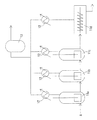
- FIG. 1 It is an example of the polycondensation reaction process figure which shows the example of a polycondensation reaction apparatus.
- A is a cross-sectional view of a polycondensation reaction apparatus provided with a scraper
- (b) is a bb cross-sectional view of the cross-sectional view of (a).
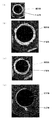
- (A), (b), (c), and (d) are figures which show the mode of the deposit
- the present invention is a method for producing a polycarbonate resin in which a polycarbonate resin is continuously produced using a plurality of polycondensation reaction apparatuses.
- the polycarbonate resin that is the production object in the present invention is preferably a polymer compound produced by polycondensation reaction (ester exchange reaction) of a carbonic acid diester and a dihydroxy compound.
- Carbonated diester examples include substituted diphenyl carbonates such as diphenyl carbonate (DPC) and ditolyl carbonate, and dialkyl carbonates such as dimethyl carbonate, diethyl carbonate, and di-t-butyl carbonate. These carbonic acid diesters can be used alone or in admixture of two or more.
- DPC diphenyl carbonate
- dialkyl carbonates such as dimethyl carbonate, diethyl carbonate, and di-t-butyl carbonate.
- the carbonic acid diester may preferably be substituted with dicarboxylic acid or dicarboxylic acid ester in an amount of 50 mol% or less, more preferably 30 mol% or less.
- Representative dicarboxylic acids or dicarboxylic acid esters include terephthalic acid, isophthalic acid, diphenyl terephthalate, and diphenyl isophthalate. When substituted with such a dicarboxylic acid or dicarboxylic acid ester, a polyester carbonate is obtained.
- carbonic acid diesters including the above substituted dicarboxylic acid or dicarboxylic acid ester; the same shall apply hereinafter
- the carbonic acid diester is used in an amount of 1.01 to 1.30 times (molar ratio), preferably 1.02 to 1.20 times (molar ratio) with respect to the dihydroxy compound.
- the molar ratio is too small, the amount of terminal hydroxyl groups of the obtained polycarbonate resin increases, and the thermal stability of the polycarbonate resin tends to deteriorate.
- the dihydroxy compound is a compound having two hydroxyl groups in the molecule.
- the molecule has one or more aromatic rings, and each of the two hydroxyl groups is bonded to the aromatic ring.
- Aromatic dihydroxy compounds are preferably used.
- aromatic dihydroxy compounds include, for example, bis (4-hydroxydiphenyl) methane, 2,2-bis (4-hydroxyphenyl) propane, and 2,2-bis (4-hydroxy-3-methyl).
- Phenyl) propane 2,2-bis (4-hydroxy-3-tert-butylphenyl) propane, 2,2-bis (4-hydroxy-3,5-dimethylphenyl) propane, 2,2-bis (4- Bisphenols such as hydroxy-3,5-dibromophenyl) propane, 4,4-bis (4-hydroxyphenyl) heptane, 1,1-bis (4-hydroxyphenyl) cyclohexane; 4,4′-dihydroxybiphenyl, 3 , 3 ′, 5,5′-tetramethyl-4,4′-dihydroxybiphenyl and the like; bis (4-hydroxyphenol) Nyl) sulfone, bis (4-hydroxyphenyl) sulfide, bis (4-hydroxyphenyl) ether, bis (4-hydroxyphenyl) ketone and
- transesterification catalyst In the transesterification reaction, a transesterification catalyst is used.
- the transesterification catalyst include a catalyst usually used for producing a polycarbonate by a transesterification method, and are not particularly limited.
- group 1 element excluding hydrogen
- long-period group 2 At least one basic compound selected from the group consisting of elemental compounds (hereinafter sometimes referred to as “Group 2 elements”), basic boron compounds, basic phosphorus compounds, basic ammonium compounds, and amine compounds.
- Group 2 elements At least one basic compound selected from the group consisting of elemental compounds (hereinafter sometimes referred to as “Group 2 elements”), basic boron compounds, basic phosphorus compounds, basic ammonium compounds, and amine compounds.
- Compounds Compounds.
- these transesterification catalysts practically, at least one compound selected from the group consisting of compounds of group 1 elements (excluding hydrogen) and compounds of group 2 elements is preferable.
- These transesterification catalysts may be used alone or in combination of
- the amount of the transesterification catalyst used is usually preferably 1 ⁇ 10 ⁇ 9 to 1 ⁇ 10 ⁇ 1 mol, more preferably 1 ⁇ 10 ⁇ 7 to 1 ⁇ 10 ⁇ 3 mol, still more preferably 1 mol of the dihydroxy compound. Used at 1 ⁇ 10 ⁇ 7 to 1 ⁇ 10 ⁇ 5 mol.
- Examples of the compounds of Group 1 elements include inorganic compounds such as hydroxides, carbonates, hydrogen carbonate compounds of Group 1 elements (excluding hydrogen); Group 1 elements (excluding hydrogen) And organic compounds such as salts with alcohols, phenols and organic carboxylic acids.
- a group 1 element except hydrogen
- lithium, sodium, potassium, rubidium, and cesium are mentioned, for example.
- cesium compounds and potassium compounds are preferable, and cesium carbonate, cesium hydrogen carbonate, cesium hydroxide, potassium acetate, and potassium carbonate are particularly preferable.
- Group 2 element compounds examples include hydroxides such as beryllium, magnesium, calcium, strontium and barium, inorganic compounds such as carbonates; alcohols such as beryllium, magnesium, calcium, strontium and barium. And salts with phenols and organic carboxylic acids. Of these Group 2 elements (excluding hydrogen), magnesium compounds are preferred.
- Examples of the basic boron compound include sodium salts, potassium salts, lithium salts, calcium salts, magnesium salts, barium salts, and strontium salts of boron compounds.
- the boron compound for example, tetramethylboron, tetraethylboron, tetrapropylboron, tetrabutylboron, trimethylethylboron, trimethylbenzylboron, trimethylphenylboron, triethylmethylboron, triethylbenzylboron, triethylphenylboron, tributyl Examples include benzylboron, tributylphenylboron, tetraphenylboron, benzyltriphenylboron, methyltriphenylboron, and butyltriphenylboron.
- Examples of the basic phosphorus compound include triethylphosphine, tri-n-propylphosphine, triisopropylphosphine, tri-n-butylphosphine, triphenylphosphine, tris (pt-butylphenyl) phosphine, and tributyl.
- Examples thereof include trivalent phosphorus compounds such as phosphine, and quaternary phosphonium salts derived from these compounds. Of these, triphenylphosphine, tris (pt-butylphenyl) phosphine, and the like are preferable.
- Examples of the basic ammonium compound include tetramethylammonium hydroxide, tetraethylammonium hydroxide, tetrapropylammonium hydroxide, tetrabutylammonium hydroxide, trimethylethylammonium hydroxide, trimethylbenzylammonium hydroxide, trimethylphenylammonium hydroxide.
- triethylmethylammonium hydroxide triethylbenzylammonium hydroxide, triethylphenylammonium hydroxide, tributylbenzylammonium hydroxide, tributylphenylammonium hydroxide, tetraphenylammonium hydroxide, benzyltriphenylammonium hydroxide, Tilt Li phenyl ammonium hydroxide, butyltriphenyl ammonium hydroxide, and the like. Of these, tetramethylammonium hydroxide and the like are preferable.
- Examples of the amine compound include 4-aminopyridine, 2-aminopyridine, N, N-dimethyl-4-aminopyridine, 4-diethylaminopyridine, 2-hydroxypyridine, 2-methoxypyridine, 4- Examples include methoxypyridine, 2-dimethylaminoimidazole, 2-methoxyimidazole, imidazole, 2-mercaptoimidazole, 2-methylimidazole, and aminoquinoline.
- the polycarbonate resin is prepared by preparing a mixture of the above-mentioned dihydroxy compound and carbonic acid diester using a raw material preparation device (raw material preparation step), and subjecting the raw material mixture to a polycondensation reaction using a reaction device in the presence of the transesterification catalyst. (Polycondensation step).
- a raw material preparation device raw material preparation step
- a polycondensation reaction using a reaction device in the presence of the transesterification catalyst.
- Polycondensation step As the reaction system, a batch system, a continuous system, a combination thereof, or the like can be used. In the present invention, the raw material preparation process and the polycondensation process are performed in a continuous system.
- Polycarbonate resin after the polycondensation step, stop the reaction and devolatilize and remove unreacted raw materials and reaction by-products in the polymerization reaction solution, add a heat stabilizer, release agent, colorant, etc., necessary Depending on the process, it is manufactured through a process of forming pellets having a predetermined particle diameter.
- the raw material mixture is sent in a molten state to a plurality of reactors as shown in FIG. 1 and subjected to a polycondensation reaction.
- This polycondensation reaction is usually carried out continuously in a reactor of 2 or more, preferably 3 to 7 groups.
- Specific reaction conditions include temperature: 150 ° C. to 320 ° C., pressure: normal pressure to 0.01 Torr (1.3 Pa), average residence time: 5 to 300 minutes, preferably temperature: 180 to 310 ° C. Pressure: 20 to 0.05 Torr (2.7 kPa to 6.7 Pa), Average residence time: 60 to 150 minutes
- reaction conditions are gradually increased to higher temperatures and higher vacuums. Set to.
- a plurality of reactors including a vertical reactor are provided to increase the average molecular weight of the polycarbonate resin.
- 3 to 6 groups, preferably 4 to 5 groups are installed.
- FIG. 1 As a specific example, in FIG. 1, three vertical reactors 11a, 11b, and 11c and one horizontal reactor 11d are used.
- the melt of the raw material mixture A is supplied to the first vertical reactor 11a, and the polycondensation reaction is started in the presence of the transesterification catalyst.
- the reaction mixture is sequentially sent to the vertical reactor 11b, vertical reactor 11c, and horizontal reactor 11d to advance the polycondensation reaction.
- phenol is produced as a by-product, which is liquefied by a heat exchanger and sent to the phenol tank 13.
- the phenol in the phenol tank 13 is appropriately treated and reused as a raw material for a dihydroxy compound or a carbonic acid diester compound.
- a horizontal reactor 11d is used as the latter stage reactor of the group of reactors. This increases the viscosity as the polycondensation reaction proceeds, so that the latter stage has a high viscosity. This is to make the stirring in the easier.
- the polycarbonate resin obtained in this polycondensation step is then devolatilized and cooled.
- Examples of the vertical and horizontal reactors include, for example, a stirred tank reactor, a thin film reactor, a centrifugal thin film evaporation reactor, a surface renewal biaxial kneading reactor, a biaxial horizontal stirred reactor, and a wet wall type A reactor, a perforated plate type reactor that polymerizes while freely dropping, a perforated plate type reactor with wire that polymerizes while dropping along a wire, and the like are used.
- a stirring tank type reactor and a biaxial horizontal type stirring reactor are preferable.
- Examples of the type of agitator blades in the vertical reactor include turbine blades, paddle blades, fiddler blades, anchor blades, full zone blades (manufactured by Shinko Pantech Co., Ltd.), Sunmeler blades (manufactured by Mitsubishi Heavy Industries, Ltd.), Max Blend blades (Sumitomo) Heavy machinery industry), helical ribbon blades, twisted lattice blades (manufactured by Hitachi, Ltd.), and the like.
- a stirring blade a Max blend blade (made by Sumitomo Heavy Industries, Ltd.) and a helical ribbon blade are preferable.
- the horizontal reactor refers to a reactor in which the rotating shaft of the stirring blade is horizontal (horizontal direction).
- a stirring blade of a horizontal reactor for example, a uniaxial stirring blade such as a disk type or a paddle type; HVR, SCR, N-SCR (manufactured by Mitsubishi Heavy Industries, Ltd.), Vivolac (manufactured by Sumitomo Heavy Industries, Ltd.), or And a biaxial stirring blade such as a spectacle blade or a lattice blade (manufactured by Hitachi, Ltd.).
- the transesterification catalyst used for the polycondensation reaction of a dihydroxy compound and a carbonic acid diester is usually used in advance as an aqueous solution.
- concentration of the aqueous solution is not particularly limited, and is adjusted to an arbitrary concentration according to the solubility of the transesterification catalyst in water. Moreover, it can replace with water and other solvents, such as acetone, alcohol, toluene, and phenol, can also be selected.
- the property of water used for dissolving the transesterification catalyst is not particularly limited as long as the kind and concentration of impurities contained are constant, but usually distilled water, deionized water, and the like are preferably used.
- a polycarbonate resin is continuously produced using a plurality of reaction apparatuses.
- At least one has a stirring shaft and a scraper.
- the polycarbonate resin has a viscosity average molecular weight of preferably 14,000 or more, more preferably 18,000 or more. If the viscosity average molecular weight is less than 10,000, adhesion to the stirring shaft 15 is unlikely to occur, so there is no need to provide a scraper.
- the upper limit of the viscosity average molecular weight is preferably 30,000, and more preferably 28,000.
- the viscosity average molecular weight of the target polycarbonate resin is 30,000.
- a substance in the middle of polymerization in the reactor (hereinafter sometimes referred to as “polymerization intermediate substance”) is likely to adhere to the stirring shaft. , Will come off immediately.
- the scraper is provided in such a place, it is effective to peel off a substance that is difficult to peel off during polymerization.
- FIG. 2A shows the case where the scraper 14 is attached to the horizontal reactor 11d.
- a horizontal reactor 11d shown in FIG. 2 (a) is a device in which a stirring blade 16 is attached to a horizontally arranged stirring shaft 15, and the polymerization melt inserted from the inlet 17 is stirred by the stirring blade 16.
- the polycondensation reaction proceeds while being discharged from the discharge port 18 to the outside.
- the stirring shaft 16 is often not provided with the stirring blade 16. In this case, a substance in the middle of polymerization adheres to the stirring shaft 15 in the vicinity of the discharge port 18 and is difficult to peel off.
- the reactor equipped with the scraper needs to be provided at least one of the reactors within the range of the viscosity average molecular weight at the outlet of the reactor.
- a scraper for all of them.
- this reactor it is preferable to use a horizontal reactor arranged last, from the viewpoint of viscosity average molecular weight.
- the melt viscosity at the reactor outlet of the reactor equipped with the scraper is 500 poise or more, preferably 1000 poise or more, more preferably 5000 poise or more. If the melt viscosity is less than 500 poise, it is difficult for the agitation shaft 15 to adhere to the melt, so that it is not necessary to provide a scraper.
- the upper limit of melt viscosity is 50,000 poise, preferably 30,000 poise, more preferably 25,000 poise, and most preferably 15,000 poise. If the melt viscosity exceeds 50,000 poise, there is a possibility that deposits may also be generated on the scraper, which is not preferable.
- the temperature of the polycarbonate resin at the reactor outlet of the reactor equipped with the scraper is 260 ° C. or higher, preferably 265 ° C. or higher, more preferably 270 ° C. or higher. If the temperature of the polycarbonate resin is lower than 260 ° C., the melt viscosity of the polycarbonate resin becomes too high, and there is a possibility that deposits may also be generated on the scraper.
- the upper limit of the temperature of the polycarbonate resin is 320 ° C, preferably 310 ° C, and most preferably 300 ° C. If the temperature of the polycarbonate resin exceeds 320 ° C., the polycarbonate resin may be yellowed, which is not preferable.
- the scraper 14 is thinned to form a scraping portion, and is disposed in the vicinity of the stirring shaft 15.
- the tip portion As shown in FIG. 2 (b), it is possible to more easily remove the deposits on the stirring shaft 15.
- the distance between the scraping portion 14a of the scraper 14 and the stirring shaft 15 is preferably 30 mm or less, and more preferably 20 mm or less. When it exceeds 30 mm, there is a possibility that the attached substance cannot be sufficiently peeled off.
- the distance between the scraping part and the stirring shaft 15 is preferably 1 mm or more, and more preferably 5 mm or more. If it is less than 1 mm, the scraping part and the stirring shaft 15 may come into contact with each other.
- the scraping portion 14a of the scraper 14 is below the shaft center of the stirring shaft. By doing in this way, the scraped deposits can be dropped downward without coming into contact with the stirring shaft again.
- the length of the scraping portion 14a of the scraper 14 is preferably 30% or less, more preferably 20% or less with respect to the total length of the stirring shaft 15. If it is longer than 30%, the resin adheres to the central portion of the scraper, and there is a possibility that a fixed matter is generated on the scraper.
- the lower limit of the length of the scraping portion 14a is preferably 3% and more preferably 5% with respect to the total length of the stirring shaft. If it is shorter than 3%, the scraping efficiency of the deposit may be reduced. Note that the length of the scraping portion 14a of the scraper 14 is premised on a length that does not contact the stirring blade 16.
- the installation position of the scraper is on the outlet side from the center. This is because the viscosity average molecular weight increases toward the downstream side, and deposits are easily generated.
- the peripheral speed of the stirring shaft 15 is preferably 5 cm / s or more, more preferably 7 cm / s or more, and still more preferably 8 cm / s or more. When it is slower than 5 cm / s, the strength of the stirring shaft is lowered, and the stirring shaft may be broken when operated for a long time.
- the upper limit of the peripheral speed is preferably 15 cm / s, and more preferably 10 cm / s. When the speed is higher than 15 cm / s, the polymerizing substance adhering to the stirring shaft 15 may be lifted above the rotating shaft before falling below the stirring shaft 15, and the adhesion may proceed without being able to peel off.
- the diameter of the stirring shaft 15 is preferably 200 mm or more, more preferably 300 mm or more, and still more preferably 400 mm or more. If it is smaller than 200 mm, the strength of the stirring shaft is lowered, and the stirring shaft may be broken when it is operated for a long time.
- the upper limit of the diameter of the stirring shaft 15 is preferably 600 mm, and more preferably 500 mm. If it is larger than 600 mm, even if the peripheral speed of the stirring shaft 15 is in the above range, the linear speed on the surface of the stirring shaft 15 becomes too high, and the substance in the middle of polymerization adhering to the stirring shaft 15 cannot be peeled off and proceeds instead of adhering. There is a case.
- the material of the scraper 14 is preferably made of stainless steel, more preferably SUS304, SUS304L, SUS310S, SUS316, SUS316L, and most preferably SUS316L, SUS310S.
- the surface of the scraper 14 is usually surface-treated, and preferable surface treatment is buffing, electrolytic polishing, acid treatment, heat treatment, various platings, coating treatment, and more preferable surface treatment is buffing. Electrolytic polishing is performed later.
- the surface roughness (Rmax) of the scraper 14 is preferably 100 ⁇ m or less, more preferably 10 ⁇ m or less, and most preferably 1 ⁇ m or less. If this surface roughness (Rmax) is too large, the peeled deposits remain on the scraper, and foreign matter may increase.
- the surface roughness (Rmax) is preferably low, but the construction is difficult, so 0.01 ⁇ m or more is preferable, and 0.1 ⁇ m or more is more preferable.
- the surface roughness of the scraper 14 is sufficient if it is 0.1 ⁇ m or more.
- melt viscosity The polycarbonate resin dried at 120 ° C. for 5 hours was heated to 280 ° C. using a capillary rheometer (manufactured by Toyo Seiki Co., Ltd.) having a die diameter of 1 mm ⁇ ⁇ 30 mm, and the melt viscosity was adjusted at a shear rate of 122 (sec ⁇ 1 ). It was measured.
- an aqueous cesium carbonate solution was used as a catalyst at a ratio of 0.5 ⁇ mol (1.0 ⁇ mol per 1 mol of bisphenol A as a metal amount) per 1 mol of bisphenol A Continuous supply.
- the reaction liquid discharged from the bottom of the reactor is continuously continuously supplied to the second and third vertical stirring reactors (capacity 10 m 3 ) and the fourth horizontal reactor (capacity 15 m 3 ), and the fourth reaction. It was extracted from the polymer outlet at the bottom of the vessel.
- the fourth reactor a biaxial horizontal reactor was used.
- the peripheral speed of the stirring shaft of this fourth polymerization tank was 8.8 cm / s, and the diameter of the stirring shaft was 560 mm.
- the reaction conditions in the second to fourth reactors were the second reactor (260 ° C., 4.00 ⁇ 10 3 Pa, 75 rpm), the third reactor (270 ° C., 200 Pa, 75 rpm), and the fourth reaction, respectively.
- a vessel (280 ° C., 67 Pa, 4 rpm) was set to high temperature and high vacuum as the reaction progressed.
- the liquid level was controlled so that the average residence time of the second and third reactors was 60 minutes and the average residence time of the fourth reactor was 90 minutes. Distillation was also performed.
- the viscosity average molecular weight (Mv) of the reaction solution at the outlet of the fourth reactor was 21,000, and the melt viscosity at 280 ° C. was about 10,000 Poise.
- Example 1 As shown in FIG. 2, the horizontal reactor 11d was operated in the same manner as in Comparative Example 1 except that a scraper was installed. Moreover, as shown in FIG.2 (b), the shape of a scraper is thin like a blade, and this front-end
- the number of fish eyes of the polycarbonate resin pellets was 25. Further, 7 days after the start of operation, a slight amount of deposit was generated between the scraper and the stirring shaft, but no deposit was dropped. The number of fish eyes of the polycarbonate resin pellet at this time was 31. Further, even after 2 months of operation, no deposits were dropped, and the number of fish eyes in the polycarbonate resin pellets at this time was 28.
- Example 2 As shown in FIG. 2, a simulation was performed in the same manner as in Comparative Example 3 except that a scraper was installed in the horizontal reactor 11d. Moreover, as shown in FIG.2 (b), the shape of the scraper was thin like a blade, and this tip portion was used as a scraping portion. The distance between the tip of the scraper and the stirring shaft was set to 10 mm. The length of the tip of the scraper was 6% of the total length of the stirring shaft. The result of this polymer flow simulation is shown in FIG. Moreover, the average thickness of the deposit in the polymer flow simulation was 10.3 mm in Example 2.
- the method for producing a polycarbonate resin according to the present invention can prevent the introduction of foreign matter that is a high molecular weight product or a highly branched product, and can efficiently and stably produce a polycarbonate resin having a small amount of foreign matter and a stable quality. It is possible, and the industrial applicability is high, such as preventing damage to the polymer filter provided in the reaction apparatus. It should be noted that the entire contents of the specification, claims, drawings and abstract of Japanese Patent Application No. 2012-078641 filed on March 30, 2012 are cited herein as disclosure of the specification of the present invention. Incorporated.
Landscapes
- Chemical & Material Sciences (AREA)
- Health & Medical Sciences (AREA)
- Chemical Kinetics & Catalysis (AREA)
- Medicinal Chemistry (AREA)
- Polymers & Plastics (AREA)
- Organic Chemistry (AREA)
- Polyesters Or Polycarbonates (AREA)
Description
本発明は、ポリカーボネート樹脂の製造方法に関し、詳しくは、重縮合反応装置の撹拌軸への付着物を減少させ、製品への異物混入を抑制するポリカーボネート樹脂の製造方法に関する。
ポリカーボネート樹脂の製造方法として、ジヒドロキシ化合物と炭酸ジエステルとを重縮合させる溶融法等が知られている。
この方法においては、特許文献1に記載されているように、複数の反応装置を用いて、連続的に重縮合反応を行い、ポリカーボネート樹脂を製造する方法が知られている。
ところで、前記の連続重合においては、重合反応が進むにつれ、後の反応装置中に生成するポリカーボネート樹脂の分子量は増大していく。このため、重合反応が進んでいくと、後の方の反応装置においては、高粘度のポリカーボネート樹脂が存在することとなる。
このとき、ポリカーボネート樹脂の粘度が増大するにつれ、反応装置内においては、撹拌軸等へのポリカーボネート樹脂の付着が生じる。この付着したポリカーボネート樹脂は、他のポリカーボネート樹脂との接触等が少ない場合、徐々に重縮合反応が進行し、粘性が上がり、撹拌軸等に固着することがある。また、この固着物は、分岐構造を多く有する高分岐量物となりやすい。
前記ポリカーボネート樹脂の固着物は、通常製造されるポリカーボネート樹脂との相溶性は乏しく、また、黄変している場合が多い。このため、撹拌軸等から落下等をして脱離すると、ポリカーボネート樹脂に異物として混在することとなり、色調の悪化、異物の増加の原因となる。また、この落下物が大きい場合、反応装置内に設けられているポリマーフィルタ等を破損することもある。
そこで、本発明は、ポリカーボネート樹脂の製造において、異物の発生を抑制し、得られるポリカーボネート樹脂の品質を保持することを目的とする。
すなわち、本発明は以下の要旨を有するものである。
(1)複数の反応装置を用いて連続的にポリカーボネート樹脂を製造する方法であって、
前記反応装置出口におけるポリカーボネート樹脂の粘度平均分子量が10,000以上となるように設定された反応装置のうちの少なくとも一つが、攪拌軸とスクレーパーを具備していることを特徴とするポリカーボネート樹脂の製造方法。
(2)前記ポリカーボネート樹脂が、炭酸ジエステルとジヒドロキシ化合物とをエステル交換触媒の存在下に、重縮合反応させて得られる上記(1)に記載のポリカーボネート樹脂の製造方法。
(3)前記炭酸ジエステルが、置換もしくは無置換のジフェニルカーボネート及びジアルキルカーボネートからなる群より選ばれる少なくとも1種である上記(2)に記載のポリカーボネート樹脂の製造方法。
(4)前記ジヒドロキシ化合物が、分子内に一つ以上の芳香環を有し、二つの水酸基がそれぞれ芳香環に結合された芳香族ジヒドロキシ化合物である上記(2)又は(3)に記載のポリカーボネート樹脂の製造方法。
(5)前記エステル交換触媒が、長周期型周期表第1族元素(水素を除く)の化合物、長周期型周期表第2族元素の化合物、塩基性ホウ素化合物、塩基性リン化合物、塩基性アンモニウム化合物、及びアミン系化合物からなる群から選ばれる少なくとも1種の塩基性化合物である上記(2)乃至(4)のいずれかに記載のポリカーボネート樹脂の製造方法。
(6)前記スクレーパーの掻き取り部と前記撹拌軸との距離が、30mm以下である上記(1)乃至(5)のいずれかに記載のポリカーボネート樹脂の製造方法。
(7)前記スクレーパーの掻き取り部と前記撹拌軸との距離が、1mm以上である上記(1)乃至(6)のいずれかに記載のポリカーボネート樹脂の製造方法。
(8)前記攪拌軸とスクレーパーを具備した反応装置が、横型反応器である上記(1)乃至(7)のいずれかに記載のポリカーボネート樹脂の製造方法。
(9)前記スクレーパーの掻き取り部が、前記攪拌軸の軸中心より下方にある上記(1)乃至(8)のいずれかに記載のポリカーボネート樹脂の製造方法。
(10)前記スクレーパーの掻き取り部の長さが、前記攪拌軸の全長に対して30%以下3%以上である上記(1)乃至(9)のいずれかに記載のポリカーボネート樹脂の製造方法。
(11)前記攪拌軸の周速が、5cm/s以上15cm/s以下である上記(1)乃至(10)のいずれかに記載のポリカーボネート樹脂の製造方法。
(12)前記攪拌軸の直径が、200mm以上600mm以下である上記(1)乃至(11)のいずれかに記載のポリカーボネート樹脂の製造方法。
(13)前記ポリカーボネート樹脂の粘度平均分子量が、18,000以上である上記(1)乃至(12)のいずれかに記載のポリカーボネート樹脂の製造方法。
(14)前記ポリカーボネート樹脂の溶融粘度が、50,000Poise以下である上記(1)乃至(13)のいずれかに記載のポリカーボネート樹脂の製造方法。
(1)複数の反応装置を用いて連続的にポリカーボネート樹脂を製造する方法であって、
前記反応装置出口におけるポリカーボネート樹脂の粘度平均分子量が10,000以上となるように設定された反応装置のうちの少なくとも一つが、攪拌軸とスクレーパーを具備していることを特徴とするポリカーボネート樹脂の製造方法。
(2)前記ポリカーボネート樹脂が、炭酸ジエステルとジヒドロキシ化合物とをエステル交換触媒の存在下に、重縮合反応させて得られる上記(1)に記載のポリカーボネート樹脂の製造方法。
(3)前記炭酸ジエステルが、置換もしくは無置換のジフェニルカーボネート及びジアルキルカーボネートからなる群より選ばれる少なくとも1種である上記(2)に記載のポリカーボネート樹脂の製造方法。
(4)前記ジヒドロキシ化合物が、分子内に一つ以上の芳香環を有し、二つの水酸基がそれぞれ芳香環に結合された芳香族ジヒドロキシ化合物である上記(2)又は(3)に記載のポリカーボネート樹脂の製造方法。
(5)前記エステル交換触媒が、長周期型周期表第1族元素(水素を除く)の化合物、長周期型周期表第2族元素の化合物、塩基性ホウ素化合物、塩基性リン化合物、塩基性アンモニウム化合物、及びアミン系化合物からなる群から選ばれる少なくとも1種の塩基性化合物である上記(2)乃至(4)のいずれかに記載のポリカーボネート樹脂の製造方法。
(6)前記スクレーパーの掻き取り部と前記撹拌軸との距離が、30mm以下である上記(1)乃至(5)のいずれかに記載のポリカーボネート樹脂の製造方法。
(7)前記スクレーパーの掻き取り部と前記撹拌軸との距離が、1mm以上である上記(1)乃至(6)のいずれかに記載のポリカーボネート樹脂の製造方法。
(8)前記攪拌軸とスクレーパーを具備した反応装置が、横型反応器である上記(1)乃至(7)のいずれかに記載のポリカーボネート樹脂の製造方法。
(9)前記スクレーパーの掻き取り部が、前記攪拌軸の軸中心より下方にある上記(1)乃至(8)のいずれかに記載のポリカーボネート樹脂の製造方法。
(10)前記スクレーパーの掻き取り部の長さが、前記攪拌軸の全長に対して30%以下3%以上である上記(1)乃至(9)のいずれかに記載のポリカーボネート樹脂の製造方法。
(11)前記攪拌軸の周速が、5cm/s以上15cm/s以下である上記(1)乃至(10)のいずれかに記載のポリカーボネート樹脂の製造方法。
(12)前記攪拌軸の直径が、200mm以上600mm以下である上記(1)乃至(11)のいずれかに記載のポリカーボネート樹脂の製造方法。
(13)前記ポリカーボネート樹脂の粘度平均分子量が、18,000以上である上記(1)乃至(12)のいずれかに記載のポリカーボネート樹脂の製造方法。
(14)前記ポリカーボネート樹脂の溶融粘度が、50,000Poise以下である上記(1)乃至(13)のいずれかに記載のポリカーボネート樹脂の製造方法。
本発明によれば、スクレーパーを反応器内の撹拌軸近傍に配するので、撹拌軸に付着するポリカーボネート樹脂を掻き取ることができる。これにより高分子量物や高分岐量物である異物の混入を防ぎ、異物の少ないポリマーを効率的に製造することが可能となり、品質の安定したポリカーボネート樹脂を安定的に製造することができる。そして、反応装置内に設けられているポリマーフィルターの破損を防ぐこともできる。
本発明は、複数の重縮合反応装置を用いて連続的にポリカーボネート樹脂を製造するポリカーボネート樹脂の製造方法である。
(ポリカーボネート樹脂)
本発明における製造対象物であるポリカーボネート樹脂とは、炭酸ジエステルとジヒドロキシ化合物とを重縮合反応(エステル交換反応)することにより製造されるポリマー化合物であることが好ましい。
本発明における製造対象物であるポリカーボネート樹脂とは、炭酸ジエステルとジヒドロキシ化合物とを重縮合反応(エステル交換反応)することにより製造されるポリマー化合物であることが好ましい。
(炭酸ジエステル)
炭酸ジエステルとしては、例えば、ジフェニルカーボネート(DPC)、ジトリルカーボネート等の置換ジフェニルカーボネート、ジメチルカーボネート、ジエチルカーボネート、ジ-t-ブチルカーボネート等のジアルキルカーボネートが挙げられる。これらの炭酸ジエステルは、単独で又は2種以上を混合して用いることができる。
炭酸ジエステルとしては、例えば、ジフェニルカーボネート(DPC)、ジトリルカーボネート等の置換ジフェニルカーボネート、ジメチルカーボネート、ジエチルカーボネート、ジ-t-ブチルカーボネート等のジアルキルカーボネートが挙げられる。これらの炭酸ジエステルは、単独で又は2種以上を混合して用いることができる。
また、前記の炭酸ジエステルは、好ましくはその50モル%以下、さらに好ましくは30モル%以下の量を、ジカルボン酸又はジカルボン酸エステルで置換してもよい。
代表的なジカルボン酸又はジカルボン酸エステルとしては、テレフタル酸、イソフタル酸、テレフタル酸ジフェニル、イソフタル酸ジフェニル等が挙げられる。このようなジカルボン酸又はジカルボン酸エステルで置換した場合には、ポリエステルカーボネートが得られる。
代表的なジカルボン酸又はジカルボン酸エステルとしては、テレフタル酸、イソフタル酸、テレフタル酸ジフェニル、イソフタル酸ジフェニル等が挙げられる。このようなジカルボン酸又はジカルボン酸エステルで置換した場合には、ポリエステルカーボネートが得られる。
これら炭酸ジエステル(前記の置換したジカルボン酸又はジカルボン酸エステルを含む。以下同じ。)は、前記芳香族ジヒドロキシ化合物に対して過剰に用いられる。すなわち、炭酸ジエステルは、ジヒドロキシ化合物に対して、1.01~1.30倍量(モル比)、好ましくは1.02~1.20倍量(モル比)で用いられる。モル比が小さすぎると、得られるポリカーボネート樹脂の末端水酸基量が多くなり、ポリカーボネート樹脂の熱安定性が悪化する傾向となる。また、モル比が大きすぎると、エステル交換反応の反応速度が低下し、所望の分子量を有するポリカーボネート樹脂の生産が困難となる場合や、ポリカーボネート樹脂中の炭酸ジエステルの残存量が多くなり、成形加工時や成形品としたときの臭気の原因となる場合がある。
(ジヒドロキシ化合物)
ジヒドロキシ化合物は、分子内に二つの水酸基を有する化合物であり、この発明においては、ジヒドロキシ化合物の中でも、分子内に一つ以上の芳香環を有し、二つの水酸基がそれぞれ芳香環に結合された芳香族ジヒドロキシ化合物を用いるのが好ましい。
ジヒドロキシ化合物は、分子内に二つの水酸基を有する化合物であり、この発明においては、ジヒドロキシ化合物の中でも、分子内に一つ以上の芳香環を有し、二つの水酸基がそれぞれ芳香環に結合された芳香族ジヒドロキシ化合物を用いるのが好ましい。
このような芳香族ジヒドロキシ化合物の具体例としては、例えば、ビス(4-ヒドロキシジフェニル)メタン、2,2-ビス(4-ヒドロキシフェニル)プロパン、2,2-ビス(4-ヒドロキシ-3-メチルフェニル)プロパン、2,2-ビス(4-ヒドロキシ-3-t-ブチルフェニル)プロパン、2,2-ビス(4-ヒドロキシ-3,5-ジメチルフェニル)プロパン、2,2-ビス(4-ヒドロキシ-3,5-ジブロモフェニル)プロパン、4,4-ビス(4-ヒドロキシフェニル)ヘプタン、1,1-ビス(4-ヒドロキシフェニル)シクロヘキサン等のビスフェノール類;4,4'-ジヒドロキシビフェニル、3,3',5,5'-テトラメチル-4,4'-ジヒドロキシビフェニル等のビフェノ-ル類;ビス(4-ヒドロキシフェニル)スルホン、ビス(4-ヒドロキシフェニル)スルフィド、ビス(4-ヒドロキシフェニル)エーテル、ビス(4-ヒドロキシフェニル)ケトン等が挙げられる。これらの中でも、2,2-ビス(4-ヒドロキシフェニル)プロパン(すなわち、ビスフェノールA(BPA))が好ましい。これらの芳香族ジヒドロキシ化合物は、単独で、又は2種以上を混合して用いることができる。
(エステル交換触媒)
前記のエステル交換反応においては、エステル交換触媒が用いられる。このエステル交換触媒としては、通常、エステル交換法によりポリカーボネートを製造する際に用いられる触媒が挙げられ、特に限定されない。一般的には、例えば、長周期型周期表第1族元素(水素を除く)(以下「第1族元素(水素を除く)」と称する場合がある。)の化合物、長周期型第2族元素(以下「第2族元素」と称する場合がある。)の化合物、塩基性ホウ素化合物、塩基性リン化合物、塩基性アンモニウム化合物、及びアミン系化合物からなる群から選ばれる少なくとも1種の塩基性化合物が挙げられる。
これらのエステル交換触媒の中でも、実用的には、第1族元素(水素を除く)の化合物及び第2族元素の化合物からなる群より選ばれた少なくとも1種の化合物が好ましい。これらのエステル交換触媒は、単独で使用してもよく、2種類以上を組み合わせて使用してもよい。
前記のエステル交換反応においては、エステル交換触媒が用いられる。このエステル交換触媒としては、通常、エステル交換法によりポリカーボネートを製造する際に用いられる触媒が挙げられ、特に限定されない。一般的には、例えば、長周期型周期表第1族元素(水素を除く)(以下「第1族元素(水素を除く)」と称する場合がある。)の化合物、長周期型第2族元素(以下「第2族元素」と称する場合がある。)の化合物、塩基性ホウ素化合物、塩基性リン化合物、塩基性アンモニウム化合物、及びアミン系化合物からなる群から選ばれる少なくとも1種の塩基性化合物が挙げられる。
これらのエステル交換触媒の中でも、実用的には、第1族元素(水素を除く)の化合物及び第2族元素の化合物からなる群より選ばれた少なくとも1種の化合物が好ましい。これらのエステル交換触媒は、単独で使用してもよく、2種類以上を組み合わせて使用してもよい。
エステル交換触媒の使用量は、ジヒドロキシ化合物1モルに対して通常1×10⁻⁹~1×10⁻¹モルが好ましく、より好ましくは1×10⁻⁷~1×10⁻³モル、更に好ましくは1×10⁻⁷~1×10⁻⁵モルで用いられる。
前記の第1族元素(水素を除く)の化合物としては、第1族元素(水素を除く)の水酸化物、炭酸塩、炭酸水素化合物等の無機化合物;第1族元素(水素を除く)のアルコール類、フェノール類、有機カルボン酸類との塩等の有機化合物;等が挙げられる。ここで、第1族元素(水素を除く)としては、例えば、リチウム、ナトリウム、カリウム、ルビジウム、セシウムが挙げられる。これらの第1族元素(水素を除く)の化合物の中でも、セシウム化合物及びカリウム化合物が好ましく、特に、炭酸セシウム、炭酸水素セシウム、水酸化セシウム、酢酸カリウム、炭酸カリウムが好ましい。
また、前記の第2族元素の化合物としては、例えば、ベリリウム、マグネシウム、カルシウム、ストロンチウム、バリウム等の水酸化物、炭酸塩等の無機化合物;ベリリウム、マグネシウム、カルシウム、ストロンチウム、バリウム等のアルコール類、フェノール類、有機カルボン酸類との塩等が挙げられる。これらの第2族元素(水素を除く)の化合物の中でも、マグネシウム化合物が好ましい。
前記の塩基性ホウ素化合物としては、ホウ素化合物のナトリウム塩、カリウム塩、リチウム塩、カルシウム塩、マグネシウム塩、バリウム塩、ストロンチウム塩等が挙げられる。ここで、ホウ素化合物としては、例えば、テトラメチルホウ素、テトラエチルホウ素、テトラプロピルホウ素、テトラブチルホウ素、トリメチルエチルホウ素、トリメチルベンジルホウ素、トリメチルフェニルホウ素、トリエチルメチルホウ素、トリエチルベンジルホウ素、トリエチルフェニルホウ素、トリブチルベンジルホウ素、トリブチルフェニルホウ素、テトラフェニルホウ素、ベンジルトリフェニルホウ素、メチルトリフェニルホウ素、ブチルトリフェニルホウ素等が挙げられる。
また、前記の塩基性リン化合物としては、例えば、トリエチルホスフィン、トリ-n-プロピルホスフィン、トリイソプロピルホスフィン、トリ-n-ブチルホスフィン、トリフェニルホスフィン、トリス(p-t-ブチルフェニル)ホスフィン、トリブチルホスフィン等の3価のリン化合物、又はこれらの化合物から誘導される4級ホスホニウム塩等が挙げられる。なかでも、トリフェニルホスフィン、トリス(p-t-ブチルフェニル)ホスフィン等が好ましい。
前記の塩基性アンモニウム化合物としては、例えば、テトラメチルアンモニウムヒドロキサイド、テトラエチルアンモニウムヒドロキサイド、テトラプロピルアンモニウムヒドロキサイド、テトラブチルアンモニウムヒドロキサイド、トリメチルエチルアンモニウムヒドロキサイド、トリメチルベンジルアンモニウムヒドロキサイド、トリメチルフェニルアンモニウムヒドロキサイド、トリエチルメチルアンモニウムヒドロキサイド、トリエチルベンジルアンモニウムヒドロキサイド、トリエチルフェニルアンモニウムヒドロキサイド、トリブチルベンジルアンモニウムヒドロキサイド、トリブチルフェニルアンモニウムヒドロキサイド、テトラフェニルアンモニウムヒドロキサイド、ベンジルトリフェニルアンモニウムヒドロキサイド、メチルトリフェニルアンモニウムヒドロキサイド、ブチルトリフェニルアンモニウムヒドロキサイド等が挙げられる。なかでも、テトラメチルアンモニウムヒドロキサイド等が好ましい。
また、前記のアミン系化合物としては、例えば、4-アミノピリジン、2-アミノピリジン、N,N-ジメチル-4-アミノピリジン、4-ジエチルアミノピリジン、2-ヒドロキシピリジン、2-メトキシピリジン、4-メトキシピリジン、2-ジメチルアミノイミダゾール、2-メトキシイミダゾール、イミダゾール、2-メルカプトイミダゾール、2-メチルイミダゾール、アミノキノリン等が挙げられる。
(ポリカーボネート樹脂の製造)
次に、ポリカーボネート樹脂の製造方法について説明する。
ポリカーボネート樹脂は、原料である前記のジヒドロキシ化合物及び炭酸ジエステルの混合物を原料調製装置で調製し(原料調製工程)、これらの原料混合物を、前記エステル交換触媒の存在下、反応装置で重縮合反応をさせる(重縮合工程)ことによって得られる。
反応方式としては、バッチ式、連続式、これらの組合せ等を用いることができるが、本発明においては、原料調製工程及び重縮合工程は連続式で行う。ポリカーボネート樹脂は、重縮合工程の後、反応を停止させ重合反応液中の未反応原料や反応副生物を脱揮除去する工程、熱安定剤、離型剤、色剤等を添加する工程、必要に応じて所定の粒径のペレットに形成する工程等を経て、製造される。
次に、ポリカーボネート樹脂の製造方法について説明する。
ポリカーボネート樹脂は、原料である前記のジヒドロキシ化合物及び炭酸ジエステルの混合物を原料調製装置で調製し(原料調製工程)、これらの原料混合物を、前記エステル交換触媒の存在下、反応装置で重縮合反応をさせる(重縮合工程)ことによって得られる。
反応方式としては、バッチ式、連続式、これらの組合せ等を用いることができるが、本発明においては、原料調製工程及び重縮合工程は連続式で行う。ポリカーボネート樹脂は、重縮合工程の後、反応を停止させ重合反応液中の未反応原料や反応副生物を脱揮除去する工程、熱安定剤、離型剤、色剤等を添加する工程、必要に応じて所定の粒径のペレットに形成する工程等を経て、製造される。
(重縮合工程)
原料混合物は、溶融状態で、図1に示すような複数の反応装置に送られ、重縮合反応に供される。この重縮合反応は、通常、2基以上、好ましくは3基~7基の反応器で連続的に行われる。具体的な反応条件としては、温度:150℃~320℃、圧力:常圧~0.01Torr(1.3Pa)、平均滞留時間:5~300分、好まくは、温度:180~310℃、圧力:20~0.05Torr(2.7kPa~6.7Pa)、平均滞留時間:60~150分
原料混合物は、溶融状態で、図1に示すような複数の反応装置に送られ、重縮合反応に供される。この重縮合反応は、通常、2基以上、好ましくは3基~7基の反応器で連続的に行われる。具体的な反応条件としては、温度:150℃~320℃、圧力:常圧~0.01Torr(1.3Pa)、平均滞留時間:5~300分、好まくは、温度:180~310℃、圧力:20~0.05Torr(2.7kPa~6.7Pa)、平均滞留時間:60~150分
複数の反応装置では、重縮合反応の進行とともに副生するフェノール等のモノヒドロキシ化合物を、より効果的に系外に除去するために、前記の反応条件内で、段階的により高温、より高真空に設定する。なお、得られるポリカーボネート樹脂の色相等の品質低下を防止するためには、できるだけ低温、短滞留時間の設定が好ましい。
本発明においては、通常、竪型反応器を含む複数基の反応器を設けて、ポリカーボネート樹脂の平均分子量を増大させる。通常、3~6基、好ましくは4~5基が設置される。
具体例として、図1においては、3基の竪型反応器11a、11b、11cと、1基の横型反応器11dが用いられている。
最初の竪型反応器11aに原料混合物Aの溶融物が供給され、前記エステル交換触媒の存在下で、重縮合反応が開始される。次いで、竪型反応器11b、竪型反応器11c、横型反応器11dに反応混合物が順次送られ、重縮合反応を進行させる。この際、フェノールが副生するが、これは熱交換器で液化され、フェノールタンク13に送られる。フェノールタンク13中のフェノールは、適宜処理され、ジヒドロキシ化合物や炭酸ジエステル化合物等の原料として再利用される。
最初の竪型反応器11aに原料混合物Aの溶融物が供給され、前記エステル交換触媒の存在下で、重縮合反応が開始される。次いで、竪型反応器11b、竪型反応器11c、横型反応器11dに反応混合物が順次送られ、重縮合反応を進行させる。この際、フェノールが副生するが、これは熱交換器で液化され、フェノールタンク13に送られる。フェノールタンク13中のフェノールは、適宜処理され、ジヒドロキシ化合物や炭酸ジエステル化合物等の原料として再利用される。
一群の反応装置の後段の反応器として、横型反応器11dが用いられるが、これは、重縮合反応が進行するにつれ、粘度が上昇するので、後段においては、高粘度となっており、高粘度での撹拌をより容易にするためである。
この重縮合工程で得られたポリカーボネート樹脂は、その後、脱揮され、冷却される。
この重縮合工程で得られたポリカーボネート樹脂は、その後、脱揮され、冷却される。
前記の竪型及び横型の反応器としては、例えば、攪拌槽型反応器、薄膜反応器、遠心式薄膜蒸発反応器、表面更新型二軸混練反応器、二軸横型攪拌反応器、濡れ壁式反応器、自由落下させながら重合する多孔板型反応器、ワイヤーに沿わせて落下させながら重合するワイヤー付き多孔板型反応器等が用いられる。なかでも、反応器としては、攪拌槽型反応装置、二軸横型攪拌反応装置が好ましい。
竪型反応器の撹拌翼の形式としては、例えば、タービン翼、パドル翼、ファウドラー翼、アンカー翼、フルゾーン翼(神鋼パンテック社製)、サンメラー翼(三菱重工業社製)、マックスブレンド翼(住友重機械工業社製)、ヘリカルリボン翼、ねじり格子翼(日立製作所社製)等が挙げられる。なかでも、撹拌翼としては、マックスブレンド翼(住友重機械工業社製)、ヘリカルリボン翼が好ましい。
本発明においては、横型反応器とは、攪拌翼の回転軸が横型(水平方向)であるものをいう。横型反応器の攪拌翼としては、例えば、円板型、パドル型等の一軸タイプの撹拌翼;HVR、SCR、N-SCR(三菱重工業社製)、バイボラック(住友重機械工業社製)、あるいはメガネ翼、格子翼(日立製作所社製)等の二軸タイプの撹拌翼;等が挙げられる。
なお、ジヒドロキシ化合物と炭酸ジエステルとの重縮合反応に使用するエステル交換触媒は、通常、予め水溶液として使用される場合がある。水溶液の濃度は特に限定されず、エステル交換触媒の水に対する溶解度に応じて任意の濃度に調整される。また、水に代えて、アセトン、アルコール、トルエン、フェノール等の他の溶媒を選択することもできる。
エステル交換触媒の溶解に使用する水の性状は、含有される不純物の種類ならびに濃度が一定であれば特に限定されないが、通常、蒸留水や脱イオン水等が好ましく用いられる。
エステル交換触媒の溶解に使用する水の性状は、含有される不純物の種類ならびに濃度が一定であれば特に限定されないが、通常、蒸留水や脱イオン水等が好ましく用いられる。
本発明の製造方法においては、複数の反応装置を用いて連続的にポリカーボネート樹脂を製造するが、構成する反応装置の出口におけるポリカーボネート樹脂の粘度平均分子量が10,000以上である反応装置のうちの少なくとも一つが、攪拌軸とスクレーパー(Scraper)を具備している。
尚、前記ポリカーボネート樹脂の粘度平均分子量は、好ましくは14,000以上、更に好ましくは18,000以上である。粘度平均分子量が10,000より小さいと、撹拌軸15への付着が生じにくいので、スクレーパーを設ける必要はなくなる。一方、粘度平均分子量の上限は、30,000が好ましく、28,000がより好ましい。30,000より大きくてもよいが、目的とするポリカーボネート樹脂の粘度平均分子量は、30,000であれば十分である。
一般的に、撹拌軸には、反応装置内の重合途中の物質(以下、「重合途中物質」と称する場合がある。)が付着しやすいが、次々に該重合途中物質が送られてくるので、すぐに剥がれていく。しかし、撹拌軸には、重合途中の物質が付着しにくいものの、一旦付着すると、剥がれにくくなる場所がある。このような場所に、前記スクレーパーが具備されていると、剥がれにくい重合途中物質を剥がすのに効果的である。例として、横型反応器11dにスクレーバー14を取り付けた場合を図2(a)に示す。
尚、前記ポリカーボネート樹脂の粘度平均分子量は、好ましくは14,000以上、更に好ましくは18,000以上である。粘度平均分子量が10,000より小さいと、撹拌軸15への付着が生じにくいので、スクレーパーを設ける必要はなくなる。一方、粘度平均分子量の上限は、30,000が好ましく、28,000がより好ましい。30,000より大きくてもよいが、目的とするポリカーボネート樹脂の粘度平均分子量は、30,000であれば十分である。
一般的に、撹拌軸には、反応装置内の重合途中の物質(以下、「重合途中物質」と称する場合がある。)が付着しやすいが、次々に該重合途中物質が送られてくるので、すぐに剥がれていく。しかし、撹拌軸には、重合途中の物質が付着しにくいものの、一旦付着すると、剥がれにくくなる場所がある。このような場所に、前記スクレーパーが具備されていると、剥がれにくい重合途中物質を剥がすのに効果的である。例として、横型反応器11dにスクレーバー14を取り付けた場合を図2(a)に示す。
図2(a)に示す横型反応器11dは、水平に配された撹拌軸15に撹拌翼16を取り付けた装置であり、送入口17より挿入された重合溶融液が、撹拌翼16により撹拌されながら重縮合反応を進行させ、排出口18より外部に排出される。この排出口18付近には、外部排出をより容易にするため、撹拌軸15に撹拌翼16が設けられていない場合が多い。この場合、この排出口18付近の撹拌軸15に、重合途中物質が付着し、剥がれにくくなりやすい。このため、排出口18側の撹拌翼16が設けられていない撹拌軸15近傍に前記スクレーパーを設けることにより、この付着物の掻き取りが可能となり、この重合途中物質が付着した状態で重合が進行し、撹拌軸15に固着するのを防止できる。
また、図示しないが、竪型反応器の場合は、重合液の界面付近に重合途中物質が付着しやすいので、この付近の撹拌軸15近傍に、前記スクレーパーを設けると、この部分に付着した付着物の掻き取りが可能となり、この重合途中物質が付着した状態で重合が進行し、撹拌軸に固着するのを防止できる。
前記のスクレーパーが具備される反応器は、前記の反応装置出口における粘度平均分子量の範囲内となる反応器のうち、少なくとも1つ設ける必要がある。この条件に該当する反応器が複数ある場合、全てにスクレーパーを設けることが好ましいが、付着が特に生じやすい反応器に少なくとも設けることにより、固着化するのを効率よく防止することができる。この反応器としては、最後に配される横型反応器とするのが、粘度平均分子量の観点から好ましい。
前記のスクレーパーが具備される反応器の反応装置出口における溶融粘度は、500Poise以上、好ましくは1000Poise以上、さらに好ましくは5000Poise以上である。溶融粘度が500Poiseより小さいと、撹拌軸15への付着が生じにくいので、スクレーパーを設ける必要はなくなる。一方、溶融粘度の上限は、50,000Poise、好ましくは30,000Poise、さらに好ましくは25,000Poise、最も好ましくは15,000Poiseである。溶融粘度が50,000Poiseを超えると、該スクレーパーにも付着物が発生する虞があり好ましくない。
前記のスクレーパーが具備される反応器の反応装置出口におけるポリカーボネート樹脂の温度は、260℃以上、好ましくは265℃以上、さらに好ましくは270℃以上である。ポリカーボネート樹脂の温度が260℃より低いと、ポリカーボネート樹脂の溶融粘度が高くなり過ぎ、該スクレーパーにも付着物が発生する虞があり好ましくない。一方、ポリカーボネート樹脂の温度の上限は320℃、好ましくは310℃、最も好ましくは300℃である。ポリカーボネート樹脂の温度が320℃を超えると、ポリカーボネート樹脂が黄変する虞があり好ましくない。
前記スクレーパー14は、図2(b)に示すように、先端部が細くなって掻き取り部を構成し、前記撹拌軸15の近傍に配される。先端部を刃のように細くすることで、前記撹拌軸15の付着物の剥離をより容易に行うことができる。
前記スクレーパー14の掻き取り部14aと、前記撹拌軸15との距離は30mm以下とすることが好ましく、20mm以下とすることがより好ましい。30mmを超えると、付着物の剥離を十分にできなくなるおそれがある。一方、前記掻き取り部と、前記撹拌軸15との距離は1mm以上であることが好ましく、5mm以上であることがより好ましい。1mm未満であると、前記掻き取り部と前記撹拌軸15とが接触するおそれが生じる。
前記スクレーパー14の掻き取り部14aが、前記攪拌軸の軸中心より下方にあることが好ましい。このようにすることにより、掻き取られた付着物が再び撹拌軸に接触することなく、下方に落下させることが出来る。
前記スクレーパー14の掻き取り部14aの長さは、攪拌軸15の全長に対して30%以下が好ましく、20%以下がより好ましい。30%より長いと、スクレーパー中央部に樹脂が付着し、スクレーパー上に固着物が発生する虞がある。一方、掻き取り部14aの長さの下限は、攪拌軸の全長に対して3%が好ましく、5%がより好ましい。3%より短いと、付着物掻き取り効率が低下する虞がある。なお、前記スクレーパー14の掻き取り部14aの長さは、撹拌翼16と接触しない長さが前提である。
前記スクレーパー14を横型反応器に具備する場合は、スクレーパーの設置位置が、中心よりも出口側にあることが好ましい。これは下流側ほど粘度平均分子量が増大し、付着物が発生しやすいためである。
前記攪拌軸15の周速は、5cm/s以上が好ましく、7cm/s以上がより好ましく、8cm/s以上が更に好ましい。5cm/sより遅いと、攪拌軸強度が低下し、長期間運転した場合に攪拌軸が折損する虞がある。一方、周速の上限は、15cm/sが好ましく、10cm/sがより好ましい。15cm/sより速い場合、撹拌軸15に付着した重合途中物質が、撹拌軸15の下方で落下する前に回転軸の上方に持ち上げられ、剥離できずに付着が却って進行する場合がある。
前記攪拌軸15の直径は、200mm以上が好ましく、300mm以上がより好ましく、400mm以上が更に好ましい。200mmより小さいと、攪拌軸強度が低下し、長期間運転した場合に、攪拌軸が折損する虞がある。一方、攪拌軸15の直径の上限は、600mmが好ましく、500mmがより好ましい。600mmより大きいと、撹拌軸15の周速が上記範囲であっても、撹拌軸15表面の線速が速くなりすぎ、撹拌軸15に付着した重合途中物質が、剥離できずに付着が却って進行する場合がある。
前記スクレーパー14の材質は、好ましくはステンレス製であり、さらに好ましくはSUS304、SUS304L、SUS310S、SUS316、SUS316Lであり、最も好ましくはSUS316L、SUS310Sである。
また、前記スクレーパー14の表面は通常、表面処理がされており、好ましい表面処理は、バフ研磨、電解研磨、酸処理、加熱処理、各種メッキ、コーティング処理であり、より好ましい表面処理は、バフ研磨後に電解研磨処理するものである。さらに、前記スクレーパー14の表面粗度は、表面粗さ(Rmax)が、好ましくは100μm以下、さらに好ましくは10μm以下、最も好ましくは1μm以下である。この表面粗さ(Rmax)が大きすぎると、剥離した付着物がスクレーパー上に残ってしまい、異物が増える可能性がある。表面粗さ(Rmax)は低い方が好ましいが、施工が困難となるため、0.01μm以上が好ましく、0.1μm以上がより好ましい。前記スクレーパー14の表面粗さとしては、0.1μm以上であれば十分である。
また、前記スクレーパー14の表面は通常、表面処理がされており、好ましい表面処理は、バフ研磨、電解研磨、酸処理、加熱処理、各種メッキ、コーティング処理であり、より好ましい表面処理は、バフ研磨後に電解研磨処理するものである。さらに、前記スクレーパー14の表面粗度は、表面粗さ(Rmax)が、好ましくは100μm以下、さらに好ましくは10μm以下、最も好ましくは1μm以下である。この表面粗さ(Rmax)が大きすぎると、剥離した付着物がスクレーパー上に残ってしまい、異物が増える可能性がある。表面粗さ(Rmax)は低い方が好ましいが、施工が困難となるため、0.01μm以上が好ましく、0.1μm以上がより好ましい。前記スクレーパー14の表面粗さとしては、0.1μm以上であれば十分である。
以下、本発明の実施例によりさらに詳細に説明するが、これらに限定して解釈されるものではない。ポリカーボネート樹脂の各評価方法について、以下に説明する。
(フィッシュアイ数)
130℃で5時間乾燥したポリカーボネート樹脂ペレットを320℃で押出成形し、幅140mm、厚さ70μmのフィルムを得た。押出成形には、直径30mmの単軸押出機(いすず化工社製)を使用した。次いで、光学式異物検査装置(ダイアインスツルメンツ社製、GX40K)を使用し、フィルムの中心から選択された幅80mm×長さ1.7m×厚さ70μmのフィルムのフィッシュアイ(サイズ50~500μm)数を測定した。すなわち800mVの光量を使用し、吸収された100~300mVの光量の範囲におけるフィッシュアイ数を(A)、300mV以上の光量の範囲の数を(B)として、次式(1)より算出した。測定は2回行い、その平均値を示した。
フィッシュアイ数=(A)-(B) (1)
130℃で5時間乾燥したポリカーボネート樹脂ペレットを320℃で押出成形し、幅140mm、厚さ70μmのフィルムを得た。押出成形には、直径30mmの単軸押出機(いすず化工社製)を使用した。次いで、光学式異物検査装置(ダイアインスツルメンツ社製、GX40K)を使用し、フィルムの中心から選択された幅80mm×長さ1.7m×厚さ70μmのフィルムのフィッシュアイ(サイズ50~500μm)数を測定した。すなわち800mVの光量を使用し、吸収された100~300mVの光量の範囲におけるフィッシュアイ数を(A)、300mV以上の光量の範囲の数を(B)として、次式(1)より算出した。測定は2回行い、その平均値を示した。
フィッシュアイ数=(A)-(B) (1)
(軸付着厚み評価)
軸に付着しているポリカーボネート樹脂の平均厚みは、ポリマー流動シミュレーション(ANSYS社製、ANSYS Fluent)を用いて計測し、評価した。
軸に付着しているポリカーボネート樹脂の平均厚みは、ポリマー流動シミュレーション(ANSYS社製、ANSYS Fluent)を用いて計測し、評価した。
(粘度平均分子量)
ポリカーボネート樹脂を塩化メチレンに溶解し、塩化メチレン溶液(濃度(C)は0.6g/dl)を調製した。該塩化メチレン溶液の温度20℃における比粘度(ηsp)を、ウベローデ粘度計)を用いて測定し、下式により粘度平均分子量(Mv)を算出した。
ηsp/C=[η](1+0.28ηsp)
[η]=1.23×10⁻⁴×(Mv)0.83
ポリカーボネート樹脂を塩化メチレンに溶解し、塩化メチレン溶液(濃度(C)は0.6g/dl)を調製した。該塩化メチレン溶液の温度20℃における比粘度(ηsp)を、ウベローデ粘度計)を用いて測定し、下式により粘度平均分子量(Mv)を算出した。
ηsp/C=[η](1+0.28ηsp)
[η]=1.23×10⁻⁴×(Mv)0.83
(溶融粘度)
120℃で5時間乾燥したポリカーボネート樹脂を、ダイス径1mmφ×30mmを具備したキャピラリーレオメーター(東洋精機社製)を用い、280℃に加熱して剪断速度122(sec-1)にて溶融粘度を測定した。
120℃で5時間乾燥したポリカーボネート樹脂を、ダイス径1mmφ×30mmを具備したキャピラリーレオメーター(東洋精機社製)を用い、280℃に加熱して剪断速度122(sec-1)にて溶融粘度を測定した。
(比較例1)
ジフェニルカーボネート(三菱化学社製)とビスフェノールA(三菱化学社製)とを、一定のモル比(DPC/BPA=1.050)となるように混合し、温度155℃で原料混合物の溶融液を調製した。次いで、4400kg/時の流量で、原料導入管を介して、220℃、13.3×103Paに制御した容量10m3の第1竪型攪拌反応器内に連続供給し、平均滞留時間が60分となるように、反応器底部のポリマー排出ラインに設けられたバルブ開度を制御しつつ、液面レベルを一定に保った。また、原料溶融液の供給を開始すると同時に、触媒として、ビスフェノールAの1モルに対し、0.5μモル(金属量としてビスフェノールAの1モルに対し1.0μモル)の割合で炭酸セシウム水溶液を連続供給した。
ジフェニルカーボネート(三菱化学社製)とビスフェノールA(三菱化学社製)とを、一定のモル比(DPC/BPA=1.050)となるように混合し、温度155℃で原料混合物の溶融液を調製した。次いで、4400kg/時の流量で、原料導入管を介して、220℃、13.3×103Paに制御した容量10m3の第1竪型攪拌反応器内に連続供給し、平均滞留時間が60分となるように、反応器底部のポリマー排出ラインに設けられたバルブ開度を制御しつつ、液面レベルを一定に保った。また、原料溶融液の供給を開始すると同時に、触媒として、ビスフェノールAの1モルに対し、0.5μモル(金属量としてビスフェノールAの1モルに対し1.0μモル)の割合で炭酸セシウム水溶液を連続供給した。
反応器底部より排出された反応液は、引き続き、第2、第3の竪型攪拌反応器(容量10m3)及び第4の横型反応器(容量15m3)に逐次連続供給され、第4反応器底部のポリマー排出口から抜き出された。該第4反応器は、2軸横型反応器を使用した。この第4重合槽の攪拌軸の周速は8.8cm/s、攪拌軸の直径は560mmであった。
次に、第4反応器底部のポリマー排出口から抜き出されたポリマーを溶融状態のままで、ダイ出口にポリマーフィルターを設置した2軸押出機(日本製鋼所社製 スクリュー径0.174m、L/D=39(ここで、Lとはスクリューの直径を、Dとはスクリューの全長を意味する))に送り、p-トルエンスルホン酸ブチル(触媒として使用した炭酸セシウムに対して5倍モル量)を連続して混練し、ダイからストランド状で抜き出し、カッターで切断し、ポリカーボネート樹脂ペレット(粘度平均分子量(Mv)21,000)を得た。
次に、第4反応器底部のポリマー排出口から抜き出されたポリマーを溶融状態のままで、ダイ出口にポリマーフィルターを設置した2軸押出機(日本製鋼所社製 スクリュー径0.174m、L/D=39(ここで、Lとはスクリューの直径を、Dとはスクリューの全長を意味する))に送り、p-トルエンスルホン酸ブチル(触媒として使用した炭酸セシウムに対して5倍モル量)を連続して混練し、ダイからストランド状で抜き出し、カッターで切断し、ポリカーボネート樹脂ペレット(粘度平均分子量(Mv)21,000)を得た。
第2~第4反応器での反応条件は、それぞれ、第2反応器(260℃、4.00×10³Pa、75rpm)、第3反応器(270℃、200Pa、75rpm)、第4反応器(280℃、67Pa、4rpm)とし、反応の進行と共に、高温、高真空とした。また、反応の間は第2と第3反応器の平均滞留時間が60分、第4反応器の平均滞留時間が90分となるように液面レベルの制御を行い、同時に副生するフェノールの留去も行った。このとき第4反応器出口反応液の粘度平均分子量(Mv)は21,000、280℃での溶融粘度は約10,000Poiseであった。
また、いずれの反応器にもスクレーパーを設置しなかった。
反応器内のポリマーフィルターとしては、リーフディスク型ポリマーフィルターの市販品(日本ポール社製、絶対濾過精度20μmの金属不織布型(材質:SUS316L)を使用した。
また、いずれの反応器にもスクレーパーを設置しなかった。
反応器内のポリマーフィルターとしては、リーフディスク型ポリマーフィルターの市販品(日本ポール社製、絶対濾過精度20μmの金属不織布型(材質:SUS316L)を使用した。
運転開始後約1日後には最後に配された横型反応器11dの排出口18付近の攪拌翼の設けられていない攪拌軸に付着物が発生した。このときのポリカーボネート樹脂ペレットのフィッシュアイ数は36個であった。
また、約7日後には付着物の一部が重合液内に落下した。その直後の芳香族ポリカーボネート樹脂ペレットのフィッシュアイ数は1540個であった。
また、約7日後には付着物の一部が重合液内に落下した。その直後の芳香族ポリカーボネート樹脂ペレットのフィッシュアイ数は1540個であった。
(実施例1)
横型反応器11dに、図2に示すように、スクレーパーを設置した以外は、比較例1と同様に実施した。また、スクレーパーの形状は、図2(b)に示すように、先端が刃のように細くなっており、この先端部を掻き取り部として使用する。
スクレーパーの先端部は、スクレーパーと撹拌軸との距離は、15mmに設定した。また、スクレーパーの先端部の長さは、撹拌軸全長の6%とした。
横型反応器11dに、図2に示すように、スクレーパーを設置した以外は、比較例1と同様に実施した。また、スクレーパーの形状は、図2(b)に示すように、先端が刃のように細くなっており、この先端部を掻き取り部として使用する。
スクレーパーの先端部は、スクレーパーと撹拌軸との距離は、15mmに設定した。また、スクレーパーの先端部の長さは、撹拌軸全長の6%とした。
運転開始した約1日後のポリカーボネート樹脂ペレットのフィッシュアイ数は25個であった。
また、運転開始した7日後には、スクレーパーと攪拌軸との間にわずかに付着物が発生したが、付着物の落下は発生しなかった。このときのポリカーボネート樹脂ペレットのフィッシュアイ数は31個であった。さらに、2ヶ月運転した後でも付着物の落下は発生せず、このときのポリカーボネート樹脂ペレットのフィッシュアイ数は28個であった。
また、運転開始した7日後には、スクレーパーと攪拌軸との間にわずかに付着物が発生したが、付着物の落下は発生しなかった。このときのポリカーボネート樹脂ペレットのフィッシュアイ数は31個であった。さらに、2ヶ月運転した後でも付着物の落下は発生せず、このときのポリカーボネート樹脂ペレットのフィッシュアイ数は28個であった。
(比較例2~4)
上記ポリマー流動シミュレーションを使用して、軸付着物発生状況について検証した。すなわち、横型反応器11dの出口における粘度平均分子量(Mv21,000)及び溶融粘度(10,000Poise)において、攪拌軸にポリマーが接触した場合のポリマー流動についてシミュレーションを実施した。
なお、比較例2~4においては、スクレーパーは設置していないものとした。
撹拌軸の直径及び周速は、比較例2では280mm、5.1cm/s、比較例3では560mm、8.8cm/s、比較例4では430mm、7.9cm/sとした。
粘度平均分子量 (Mv)21,000のポリカーボネート樹脂溶融物を攪拌軸に接触させた場合のポリマー流動シミュレーションの結果を、比較例2では図3(a)に、比較例3では図3(b)に、比較例4では図3(c)に示す。また、ポリマー流動シミュレーションにおける付着物の平均厚みは、比較例2では33.3mm、比較例3では57.9mm、比較例4では49.2mmであった。
上記ポリマー流動シミュレーションを使用して、軸付着物発生状況について検証した。すなわち、横型反応器11dの出口における粘度平均分子量(Mv21,000)及び溶融粘度(10,000Poise)において、攪拌軸にポリマーが接触した場合のポリマー流動についてシミュレーションを実施した。
なお、比較例2~4においては、スクレーパーは設置していないものとした。
撹拌軸の直径及び周速は、比較例2では280mm、5.1cm/s、比較例3では560mm、8.8cm/s、比較例4では430mm、7.9cm/sとした。
粘度平均分子量 (Mv)21,000のポリカーボネート樹脂溶融物を攪拌軸に接触させた場合のポリマー流動シミュレーションの結果を、比較例2では図3(a)に、比較例3では図3(b)に、比較例4では図3(c)に示す。また、ポリマー流動シミュレーションにおける付着物の平均厚みは、比較例2では33.3mm、比較例3では57.9mm、比較例4では49.2mmであった。
(実施例2)
横型反応器11dに、図2に示すように、スクレーパーを設置した以外は、比較例3と同様にシミュレーションを実施した。また、スクレーパーの形状は、図2(b)に示すように、先端が刃のように細くなっており、この先端部を掻き取り部とした。
スクレーパーの先端部と撹拌軸との距離は、10mmに設定した。また、スクレーパーの先端部の長さは、撹拌軸全長の6%とした。
このポリマー流動シミュレーションの結果を、図3(d)に示す。また、ポリマー流動シミュレーションにおける付着物の平均厚みは、実施例2では10.3mmであった。
横型反応器11dに、図2に示すように、スクレーパーを設置した以外は、比較例3と同様にシミュレーションを実施した。また、スクレーパーの形状は、図2(b)に示すように、先端が刃のように細くなっており、この先端部を掻き取り部とした。
スクレーパーの先端部と撹拌軸との距離は、10mmに設定した。また、スクレーパーの先端部の長さは、撹拌軸全長の6%とした。
このポリマー流動シミュレーションの結果を、図3(d)に示す。また、ポリマー流動シミュレーションにおける付着物の平均厚みは、実施例2では10.3mmであった。
本発明のポリカーボネート樹脂の製造方法は、高分子量物や高分岐量物である異物の混入を防ぐことができ、異物の少ない、品質の安定したポリカーボネート樹脂を効率的、安定的に製造することが可能であり、反応装置内に設けられているポリマーフィルターの破損を防ぐこともできる等、産業上の利用可能性が高い。
なお、2012年3月30日に出願された日本特許出願2012-078641号の明細書、特許請求の範囲、図面及び要約書の全内容をここに引用し、本発明の明細書の開示として、取り入れるものである。
なお、2012年3月30日に出願された日本特許出願2012-078641号の明細書、特許請求の範囲、図面及び要約書の全内容をここに引用し、本発明の明細書の開示として、取り入れるものである。
11a,11b,11c 竪型反応器
11d 横型反応器
12 熱交換器
13 フェノールタンク
14 スクレーパー
14a スクレーパー掻き取り部
15 撹拌軸
16 撹拌翼
17 送入口
18 排出口
A 原料混合物
B ポリカーボネート樹脂
11d 横型反応器
12 熱交換器
13 フェノールタンク
14 スクレーパー
14a スクレーパー掻き取り部
15 撹拌軸
16 撹拌翼
17 送入口
18 排出口
A 原料混合物
B ポリカーボネート樹脂
Claims (14)
- 複数の反応装置を用いて連続的にポリカーボネート樹脂を製造する方法であって、
前記反応装置出口におけるポリカーボネート樹脂の粘度平均分子量が10,000以上となるように設定された反応装置のうちの少なくとも一つが、攪拌軸とスクレーパーを具備していることを特徴とするポリカーボネート樹脂の製造方法。 - 前記ポリカーボネート樹脂が、炭酸ジエステルとジヒドロキシ化合物とをエステル交換触媒の存在下に、重縮合反応させて得られることを特徴とする請求項1に記載のポリカーボネート樹脂の製造方法。
- 前記炭酸ジエステルが、置換もしくは無置換のジフェニルカーボネート及びジアルキルカーボネートからなる群より選ばれる少なくとも1種であることを特徴とする請求項2に記載のポリカーボネート樹脂の製造方法。
- 前記ジヒドロキシ化合物が、分子内に一つ以上の芳香環を有し、二つの水酸基がそれぞれ芳香環に結合された芳香族ジヒドロキシ化合物であることを特徴とする請求項2又は3に記載のポリカーボネート樹脂の製造方法。
- 前記エステル交換触媒が、長周期型周期表第1族元素(水素を除く)の化合物、長周期型周期表第2族元素の化合物、塩基性ホウ素化合物、塩基性リン化合物、塩基性アンモニウム化合物、及びアミン系化合物からなる群から選ばれる少なくとも1種の塩基性化合物であることを特徴とする請求項2乃至4のいずれか1項に記載のポリカーボネート樹脂の製造方法。
- 前記スクレーパーの掻き取り部と前記撹拌軸との距離が、30mm以下であることを特徴とする請求項1乃至5のいずれか1項に記載のポリカーボネート樹脂の製造方法。
- 前記スクレーパーの掻き取り部と前記撹拌軸との距離が、1mm以上であることを特徴とする請求項1乃至6のいずれか1項に記載のポリカーボネート樹脂の製造方法。
- 前記攪拌軸とスクレーパーを具備した反応装置が、横型反応器であることを特徴とする請求項1乃至7のいずれか1項に記載のポリカーボネート樹脂の製造方法。
- 前記スクレーパーの掻き取り部が、前記攪拌軸の軸中心より下方にあることを特徴とする請求項1乃至8のいずれか1項に記載のポリカーボネート樹脂の製造方法。
- 前記スクレーパーの掻き取り部の長さが、前記攪拌軸の全長に対して30%以下3%以上であることを特徴とする請求項1乃至9のいずれか1項に記載のポリカーボネート樹脂の製造方法。
- 前記攪拌軸の周速が、5cm/s以上15cm/s以下であることを特徴とする請求項1乃至10のいずれか1項に記載のポリカーボネート樹脂の製造方法。
- 前記攪拌軸の直径が、200mm以上600mm以下であることを特徴とする請求項1乃至11のいずれか1項に記載のポリカーボネート樹脂の製造方法。
- 前記ポリカーボネート樹脂の粘度平均分子量が、18,000以上であることを特徴とする請求項1乃至12のいずれか1項に記載のポリカーボネート樹脂の製造方法。
- 前記ポリカーボネート樹脂の溶融粘度が、50,000Poise以下であることを特徴とする請求項1乃至13のいずれか1項に記載のポリカーボネート樹脂の製造方法。
Priority Applications (3)
| Application Number | Priority Date | Filing Date | Title |
|---|---|---|---|
| IN8297DEN2014 IN2014DN08297A (ja) | 2012-03-30 | 2013-03-29 | |
| CN201380016901.3A CN104204032A (zh) | 2012-03-30 | 2013-03-29 | 聚碳酸酯树脂的制造方法 |
| KR1020147027078A KR20140145136A (ko) | 2012-03-30 | 2013-03-29 | 폴리카보네이트 수지의 제조 방법 |
Applications Claiming Priority (2)
| Application Number | Priority Date | Filing Date | Title |
|---|---|---|---|
| JP2012078641 | 2012-03-30 | ||
| JP2012-078641 | 2012-03-30 |
Publications (1)
| Publication Number | Publication Date |
|---|---|
| WO2013147223A1 true WO2013147223A1 (ja) | 2013-10-03 |
Family
ID=49260463
Family Applications (1)
| Application Number | Title | Priority Date | Filing Date |
|---|---|---|---|
| PCT/JP2013/059671 Ceased WO2013147223A1 (ja) | 2012-03-30 | 2013-03-29 | ポリカーボネート樹脂の製造方法 |
Country Status (5)
| Country | Link |
|---|---|
| JP (1) | JP2013227511A (ja) |
| KR (1) | KR20140145136A (ja) |
| CN (1) | CN104204032A (ja) |
| IN (1) | IN2014DN08297A (ja) |
| WO (1) | WO2013147223A1 (ja) |
Cited By (1)
| Publication number | Priority date | Publication date | Assignee | Title |
|---|---|---|---|---|
| WO2022202130A1 (ja) * | 2021-03-26 | 2022-09-29 | 旭化成株式会社 | ポリカーボネートの製造装置の組み立て方法、及びポリカーボネートの製造装置 |
Families Citing this family (1)
| Publication number | Priority date | Publication date | Assignee | Title |
|---|---|---|---|---|
| JP2018150453A (ja) * | 2017-03-13 | 2018-09-27 | 三菱ケミカル株式会社 | ポリブチレンサクシネートの製造方法 |
Citations (4)
| Publication number | Priority date | Publication date | Assignee | Title |
|---|---|---|---|---|
| JPS4636525Y1 (ja) * | 1968-09-17 | 1971-12-15 | ||
| JPH02126934A (ja) * | 1987-12-18 | 1990-05-15 | Davy Mckee Ag | 高粘性物質処理装置 |
| WO2002040569A1 (en) * | 2000-11-14 | 2002-05-23 | Teijin Limited | Aromatic polycarbonate, process for producing the same, and composition containing the same |
| JP2008050591A (ja) * | 2006-07-25 | 2008-03-06 | Mitsubishi Chemicals Corp | 芳香族ポリカーボネートの製造方法 |
Family Cites Families (6)
| Publication number | Priority date | Publication date | Assignee | Title |
|---|---|---|---|---|
| JPH0636525A (ja) * | 1992-07-17 | 1994-02-10 | Sanyo Electric Co Ltd | ディスク再生装置の選曲回路 |
| JPH0827265A (ja) * | 1994-07-20 | 1996-01-30 | Mitsubishi Chem Corp | 芳香族ポリカーボネートの製造方法 |
| JPH0912703A (ja) * | 1995-06-26 | 1997-01-14 | Teijin Ltd | 芳香族ポリカーボネートの製造方法 |
| JPH11310631A (ja) * | 1998-04-28 | 1999-11-09 | Daicel Chem Ind Ltd | ポリカーボネートの製造法 |
| CN2487736Y (zh) * | 2001-05-10 | 2002-04-24 | 天津大学 | 生产聚碳酸酯的卧式单转筒搅拌脱气反应器 |
| RU2380382C2 (ru) * | 2006-07-25 | 2010-01-27 | Мицубиси Кемикал Корпорейшн | Способ получения ароматического поликарбоната |
-
2013
- 2013-03-07 JP JP2013045717A patent/JP2013227511A/ja active Pending
- 2013-03-29 KR KR1020147027078A patent/KR20140145136A/ko not_active Withdrawn
- 2013-03-29 WO PCT/JP2013/059671 patent/WO2013147223A1/ja not_active Ceased
- 2013-03-29 CN CN201380016901.3A patent/CN104204032A/zh active Pending
- 2013-03-29 IN IN8297DEN2014 patent/IN2014DN08297A/en unknown
Patent Citations (4)
| Publication number | Priority date | Publication date | Assignee | Title |
|---|---|---|---|---|
| JPS4636525Y1 (ja) * | 1968-09-17 | 1971-12-15 | ||
| JPH02126934A (ja) * | 1987-12-18 | 1990-05-15 | Davy Mckee Ag | 高粘性物質処理装置 |
| WO2002040569A1 (en) * | 2000-11-14 | 2002-05-23 | Teijin Limited | Aromatic polycarbonate, process for producing the same, and composition containing the same |
| JP2008050591A (ja) * | 2006-07-25 | 2008-03-06 | Mitsubishi Chemicals Corp | 芳香族ポリカーボネートの製造方法 |
Cited By (7)
| Publication number | Priority date | Publication date | Assignee | Title |
|---|---|---|---|---|
| WO2022202130A1 (ja) * | 2021-03-26 | 2022-09-29 | 旭化成株式会社 | ポリカーボネートの製造装置の組み立て方法、及びポリカーボネートの製造装置 |
| JP2022150566A (ja) * | 2021-03-26 | 2022-10-07 | 旭化成株式会社 | ポリカーボネートの製造装置の組み立て方法、及びポリカーボネートの製造装置 |
| KR20220144412A (ko) * | 2021-03-26 | 2022-10-26 | 아사히 가세이 가부시키가이샤 | 폴리카르보네이트의 제조 장치의 조립 방법 및 폴리카르보네이트의 제조 장치 |
| KR20230006931A (ko) * | 2021-03-26 | 2023-01-11 | 아사히 가세이 가부시키가이샤 | 폴리카르보네이트의 제조 장치의 조립 방법 및 폴리카르보네이트의 제조 장치 |
| KR102503433B1 (ko) | 2021-03-26 | 2023-02-24 | 아사히 가세이 가부시키가이샤 | 폴리카르보네이트의 제조 장치의 조립 방법 및 폴리카르보네이트의 제조 장치 |
| JP7258069B2 (ja) | 2021-03-26 | 2023-04-14 | 旭化成株式会社 | ポリカーボネートの製造装置の組み立て方法、及びポリカーボネートの製造装置 |
| KR102758319B1 (ko) | 2021-03-26 | 2025-01-23 | 아사히 가세이 가부시키가이샤 | 폴리카르보네이트의 제조 장치의 조립 방법 및 폴리카르보네이트의 제조 장치 |
Also Published As
| Publication number | Publication date |
|---|---|
| KR20140145136A (ko) | 2014-12-22 |
| JP2013227511A (ja) | 2013-11-07 |
| IN2014DN08297A (ja) | 2015-05-15 |
| CN104204032A (zh) | 2014-12-10 |
Similar Documents
| Publication | Publication Date | Title |
|---|---|---|
| RU2413739C2 (ru) | Непрерывный способ получения и установка для получения ароматического поликарбоната | |
| CN101547957B (zh) | 芳香族聚碳酸酯的制造方法 | |
| KR101211979B1 (ko) | 폴리카보네이트 수지의 제조 방법 | |
| RU2380382C2 (ru) | Способ получения ароматического поликарбоната | |
| JP2013227511A (ja) | ポリカーボネート樹脂の製造方法 | |
| JP6167570B2 (ja) | 芳香族ポリカーボネートの製造方法及び製造設備 | |
| JP2008019416A (ja) | ポリカーボネート樹脂の製造方法 | |
| JP5303847B2 (ja) | 炭酸ジエステルの精製方法及びポリカーボネート樹脂の製造方法 | |
| JP4836299B2 (ja) | 芳香族ポリカーボネート樹脂の製造方法 | |
| JP2011006553A (ja) | ポリカーボネートの製造方法 | |
| JP4957311B2 (ja) | 芳香族ポリカーボネートの連続製造方法 | |
| JP5251234B2 (ja) | 芳香族ポリカーボネート樹脂組成物の製造方法 | |
| JP5589560B2 (ja) | 芳香族ポリカーボネート樹脂の製造方法 | |
| JP5464166B2 (ja) | 炭酸ジエステルの精製方法及びポリカーボネート樹脂の製造方法 | |
| JP5942548B2 (ja) | ポリカーボネート樹脂ペレット | |
| JP5168844B2 (ja) | 芳香族ポリカーボネートの製造方法 | |
| JP5605287B2 (ja) | 連続反応装置およびポリカーボネートの連続製造方法 | |
| JP5003045B2 (ja) | 芳香族ポリカーボネートの製造方法 | |
| JP2013177636A (ja) | ポリカーボネート樹脂の製造方法 | |
| JP5245311B2 (ja) | 芳香族ポリカーボネートの製造方法 | |
| JP2008201113A (ja) | 芳香族ポリカーボネート樹脂ペレットの製造方法 |
Legal Events
| Date | Code | Title | Description |
|---|---|---|---|
| 121 | Ep: the epo has been informed by wipo that ep was designated in this application |
Ref document number: 13768333 Country of ref document: EP Kind code of ref document: A1 |
|
| ENP | Entry into the national phase |
Ref document number: 20147027078 Country of ref document: KR Kind code of ref document: A |
|
| 122 | Ep: pct application non-entry in european phase |
Ref document number: 13768333 Country of ref document: EP Kind code of ref document: A1 |
|
| NENP | Non-entry into the national phase |
Ref country code: DE |