WO2013147155A1 - 炭素工具鋼鋼帯の製造方法 - Google Patents
炭素工具鋼鋼帯の製造方法 Download PDFInfo
- Publication number
- WO2013147155A1 WO2013147155A1 PCT/JP2013/059519 JP2013059519W WO2013147155A1 WO 2013147155 A1 WO2013147155 A1 WO 2013147155A1 JP 2013059519 W JP2013059519 W JP 2013059519W WO 2013147155 A1 WO2013147155 A1 WO 2013147155A1
- Authority
- WO
- WIPO (PCT)
- Prior art keywords
- steel strip
- tool steel
- carbon tool
- quenching
- preheating
- Prior art date
- Legal status (The legal status is an assumption and is not a legal conclusion. Google has not performed a legal analysis and makes no representation as to the accuracy of the status listed.)
- Ceased
Links
Images




Classifications
-
- C—CHEMISTRY; METALLURGY
- C21—METALLURGY OF IRON
- C21D—MODIFYING THE PHYSICAL STRUCTURE OF FERROUS METALS; GENERAL DEVICES FOR HEAT TREATMENT OF FERROUS OR NON-FERROUS METALS OR ALLOYS; MAKING METAL MALLEABLE, e.g. BY DECARBURISATION OR TEMPERING
- C21D9/00—Heat treatment, e.g. annealing, hardening, quenching or tempering, adapted for particular articles; Furnaces therefor
- C21D9/52—Heat treatment, e.g. annealing, hardening, quenching or tempering, adapted for particular articles; Furnaces therefor for wires; for strips ; for rods of unlimited length
- C21D9/54—Furnaces for treating strips or wire
- C21D9/56—Continuous furnaces for strip or wire
- C21D9/60—Continuous furnaces for strip or wire with induction heating
-
- C—CHEMISTRY; METALLURGY
- C21—METALLURGY OF IRON
- C21D—MODIFYING THE PHYSICAL STRUCTURE OF FERROUS METALS; GENERAL DEVICES FOR HEAT TREATMENT OF FERROUS OR NON-FERROUS METALS OR ALLOYS; MAKING METAL MALLEABLE, e.g. BY DECARBURISATION OR TEMPERING
- C21D1/00—General methods or devices for heat treatment, e.g. annealing, hardening, quenching or tempering
- C21D1/18—Hardening; Quenching with or without subsequent tempering
-
- C—CHEMISTRY; METALLURGY
- C21—METALLURGY OF IRON
- C21D—MODIFYING THE PHYSICAL STRUCTURE OF FERROUS METALS; GENERAL DEVICES FOR HEAT TREATMENT OF FERROUS OR NON-FERROUS METALS OR ALLOYS; MAKING METAL MALLEABLE, e.g. BY DECARBURISATION OR TEMPERING
- C21D1/00—General methods or devices for heat treatment, e.g. annealing, hardening, quenching or tempering
- C21D1/34—Methods of heating
- C21D1/42—Induction heating
-
- C—CHEMISTRY; METALLURGY
- C21—METALLURGY OF IRON
- C21D—MODIFYING THE PHYSICAL STRUCTURE OF FERROUS METALS; GENERAL DEVICES FOR HEAT TREATMENT OF FERROUS OR NON-FERROUS METALS OR ALLOYS; MAKING METAL MALLEABLE, e.g. BY DECARBURISATION OR TEMPERING
- C21D8/00—Modifying the physical properties of ferrous metals or ferrous alloys by deformation combined with, or followed by, heat treatment
- C21D8/02—Modifying the physical properties of ferrous metals or ferrous alloys by deformation combined with, or followed by, heat treatment during manufacturing of plates or strips
-
- Y—GENERAL TAGGING OF NEW TECHNOLOGICAL DEVELOPMENTS; GENERAL TAGGING OF CROSS-SECTIONAL TECHNOLOGIES SPANNING OVER SEVERAL SECTIONS OF THE IPC; TECHNICAL SUBJECTS COVERED BY FORMER USPC CROSS-REFERENCE ART COLLECTIONS [XRACs] AND DIGESTS
- Y02—TECHNOLOGIES OR APPLICATIONS FOR MITIGATION OR ADAPTATION AGAINST CLIMATE CHANGE
- Y02P—CLIMATE CHANGE MITIGATION TECHNOLOGIES IN THE PRODUCTION OR PROCESSING OF GOODS
- Y02P10/00—Technologies related to metal processing
- Y02P10/25—Process efficiency
Definitions
- the present invention relates to a method for producing a carbon tool steel strip.
- a steel strip made of carbon tool steel suitable for use in springs, valves, etc. (hereinafter referred to as “carbon tool steel strip”) is generally rolled to a predetermined plate thickness, and then pre-tropical and heated zone.
- a continuous heating facility in which a quenching furnace, a spraying device, a water-cooled surface plate and a tempering furnace are continuously arranged in this order, a method of continuously quenching and tempering while unwinding a carbon tool steel strip It is manufactured.
- Patent Document 1 Japanese Patent Application Laid-Open No. 56-139627
- This manufacturing method prevents the occurrence of flaws and distortion in the carbon tool steel strip when quenching by quenching the carbon tool steel strip exiting the quenching furnace, and reduces the variation in hardness after quenching. Is something that can be done.
- Such continuous heating equipment includes a heat source that uses combustion heat obtained by burning natural gas, light oil, heavy oil or the like with a burner, or a heat source that uses heat generated by energization heating such as an electric heater.
- the carbon tool steel strip is heated by radiant heat from these heat sources, and heat transfer to the carbon tool steel strip is mainly due to radiant heating.
- the hardening furnace becomes a structure which provided the some soaking zone continuously in the part through which a carbon tool steel strip is generally passed.
- the soaking zone for example, from a pre-tropical zone in which the carbon tool steel strip is preheated to a certain temperature, and one or more heating zones in which the carbon tool steel strip is maintained at a predetermined quenching temperature. It has become. With such a configuration, the carbon tool steel strip first unwound at normal temperature and passed through a quenching furnace can be heated to the quenching temperature.
- the present inventors have studied a method for improving the production capacity by improving the heat treatment ability of the carbon tool steel strip using the continuous heating facility described in Patent Document 1 described above.
- a method of extending the length of the quenching furnace and increasing the sheet passing speed can be considered.
- the conventional radiant heating has a sufficient effect for improving the heat treatment capacity because the heating rate of the carbon tool steel strip is slow in the pretropical temperature range among the multiple soaking zones that constitute the quenching furnace. There is a problem that can not be. Further, in the case of radiant heating, there is a problem that it is not easy to control the temperature increase rate of the carbon tool steel strip in the above temperature range and other temperature conditions to an arbitrary condition.
- An object of the present invention is to provide a method for producing a carbon tool steel strip that can facilitate temperature control and improve heat treatment capacity in producing the carbon tool steel strip.
- the present invention has been made in view of the above-described problems. That is, the present invention (1) an unwinding step of unwinding the carbon tool steel strip by an unwinding machine; (2) a preheating step of preheating by induction heating while passing the carbon tool steel strip unwound by the unwinding step; (3) A quenching step in which the carbon tool steel strip preheated by the preheating step is passed through an inert gas atmosphere heated to more than 850 ° C. and not higher than 1100 ° C., and then quenched and quenched.
- the method for producing a carbon tool steel strip in which the temperature in the preheating step is 600 to 750 ° C.
- the quenching in the quenching step is the second cooling in which the carbon tool steel strip is restrained in the water-cooled surface plate and then cooled below the Ms point after the first cooling step of cooling to 200 to 350 ° C.
- a cooling step is provided, and more preferably, in the second cooling step, a plurality of the water-cooled surface plates that restrain the carbon tool steel strip are provided.
- the induction heating is preferably performed by an induction heating zone in the same atmosphere as the quenching step in which the ceramic tube is disposed inside the induction heating coil.
- the carbon tool steel strip can be rapidly heated by a preheating furnace using induction heating, temperature control is facilitated and excellent heat treatment ability is obtained. By doing so, productivity can be greatly improved. Moreover, decarburization can be reliably prevented by setting the preheating furnace and the heating furnace to an inert gas atmosphere, and a desired hardness can be obtained more reliably.
- the feature of the manufacturing method of the present invention is that when the temperature of the carbon tool steel strip is raised to the quenching temperature, the temperature is not raised only by the pre-tropical zone of the quenching furnace, but induction heating is used before the quenching furnace.
- the carbon tool steel strip can be rapidly heated by installing a preheating furnace and raising the temperature in the preheating furnace. Moreover, desired hardness can be obtained, without generating decarburization by making the atmosphere at the time of hardening and tempering into an inert gas atmosphere.
- the present invention will be described below.
- the carbon tool steel strip used in the present invention only needs to have a carbon tool steel composition defined by JIS-G-3311 (polished special strip steel). Preferred compositions are C: 0.8 to 1.2% by mass, Si: 0.1 to 0.35%, Mn: 0.1 to 0.5%, Cr: 0.05 to 0.3%.
- the balance is Fe and impurities.
- FIG. 1 shows an example of the layout of the continuous heating equipment used in the present invention.
- the present invention will be described with reference to FIG.
- a carbon tool steel strip 2 for continuously performing quenching and tempering is unwound by an unwinding machine 1 (unwinding step).
- the unrolled carbon tool steel strip 2 is passed through a preheating furnace 3 using induction heating (preheating step).
- the preheating is performed by the preheating furnace using induction heating because the carbon tool steel strip 2 generates heat by the Joule heat of the eddy current induced in the carbon tool steel strip 2 by the alternating magnetic flux. This is because it becomes possible to heat up more rapidly than in the case of heating.
- Examples of the induction heating method include a solenoid method and a transverse method.
- the solenoid method is preferable. This is because, in the case of the solenoid system, temperature control of the carbon tool steel strip is facilitated using the Ac1 point of the carbon tool steel strip 2, and the carbon tool steel strip is easily heated uniformly.
- the lower limit of the preheating temperature in this preheating step is preferably in the range of 600 ° C or higher. This is because when the preheating temperature of the carbon tool steel strip is less than 600 ° C., it may be difficult to heat the carbon tool steel strip to the quenching temperature performed after the preheating step. If so, sufficient quenching hardness cannot be obtained.
- the upper limit of the preheating temperature is preferably 750 ° C. This is because there is a risk of deformation of the carbon tool steel strip that is rapidly heated to a temperature exceeding 750 ° C. by high-frequency heating. Moreover, when the temperature of Ac1 point of the carbon tool steel strip near 750 ° C. is exceeded, the metal structure is transformed from ferrite to austenite. Austenite is non-magnetic, and solenoid-type high-frequency heating is convenient for controlling the temperature of the carbon tool steel strip in the preheating process because the heating efficiency is reduced and the overheating is prevented at a temperature higher than the Ac1 point. .
- the same inert gas atmosphere as the quenching process described later is used to prevent decarburization of the surface of the carbon tool steel strip, and the ceramic tube 11 is provided inside the induction heating coil 10 to maintain the atmosphere. It is preferable to dispose the carbon tool steel strip 2 through the ceramic tube 11. Since the ceramic tube 11 is a nonmagnetic material and induction heating does not occur, the carbon tool steel strip can be induction heated efficiently without losing power.
- the ceramic tube is preferably covered with a heat insulating material in order to reduce heat loss due to heat dissipation.
- the carbon tool steel strip 2 is passed through a quenching heating furnace 4 having an inert gas atmosphere in order to prevent decarburization, and the temperature is kept above 850 ° C. and below 1100 ° C. (quenching step).
- Suitable inert gases include nitrogen, argon, ammonia decomposition gas, etc. Among them, nitrogen is preferably used because it is easily available and inexpensive.
- the quenching heating temperature is 850 ° C. or lower, the solid solution of the carbide is insufficient and the fatigue characteristics are reduced.
- the range of the quenching heating temperature is set to be higher than 850 ° C. and not higher than 1100 ° C. If the plate passing speed in the quenching process is excessively high, the above-described effect of the heating temperature during quenching cannot be obtained. For this reason, it is preferable to adjust the sheet passing speed so that the time required for adding a quenching furnace to a part having the carbon tool steel strip is in a range of 35 to 90 seconds.
- the carbon tool steel strip 2 is quenched and quenched.
- a method of rapid cooling there is a method using a salt bath or molten metal, but the method of spraying water is the simplest method, and a thin oxide film can be formed on the surface of the carbon tool steel strip. it can.
- This thin oxide film is hard and can suppress the occurrence of flaws on the surface of the carbon tool steel strip when the water-cooled surface plate 6 described later is passed through. Therefore, it is preferable to use a method of injecting water for rapid cooling to the carbon tool steel strip 2 used in the present invention.
- a spraying device 5 installed on the exit side of the quenching furnace 4.
- the quenching process is rapidly cooled by water cooling so that the carbon tool steel strip is sandwiched after the first cooling step in which the carbon tool steel strip 2 is cooled to 200 to 350 ° C. by the spraying device 5 using compressed air and purified water.
- a martensite structure is formed by performing a second cooling step of restraining the inner surface of the platen 6 and cooling to the Ms point or lower while correcting the shape.
- the two stages of cooling are to avoid the pearlite nose in the first cooling process, reduce the strain that occurs when quenching the carbon tool steel strip 2, and perform martensitic transformation in the next second cooling process. This is because the shape of the carbon tool steel strip 2 can be adjusted.
- the reason why the lower limit of the quenching of the carbon tool steel strip 2 is set to a temperature exceeding the Ms point in the first cooling step described above is to reduce strain generated when the carbon tool steel strip 2 is quenched. This is because if the Ms point or less is set at a stroke in the first cooling step, the distortion at the time of quenching becomes too large and the shape may become unstable.
- the Ms point slightly changes depending on the composition of the carbon tool steel strip, but is approximately 180 to 190 ° C.
- a preferable lower limit of the cooling temperature in the first cooling step is a temperature that is 10 to 20 ° C. higher than the Ms point.
- the upper limit of the cooling temperature in the first cooling step is set to 350 ° C., because when the temperature exceeds 350 ° C., it may be difficult to cool to the Ms point or less in a water-cooled surface plate described later. is there.
- a plurality of water-cooled surface plates 6 used in the present invention are continuously arranged while being cooled with water. This is because the time for restraining in the water-cooled surface plate can be lengthened, so that it can be more reliably cooled to the Ms point or less, and therefore, the deformation and correction of the carbon tool steel strip 2 are more reliably performed. Because it can.
- the carbon tool steel strip 2 is heated to 300 to 450 ° C. and passed through a tempering furnace 7 in an inert gas atmosphere to perform tempering.
- the inert gas atmosphere is used to prevent decarburization of the carbon tool steel strip.
- the tempering temperature is less than 300 ° C., the hardness becomes too high.
- the tempering temperature is higher than 450 ° C., the hardness is lowered. Therefore, even if the tempering temperature is too high or too low, an appropriate hardness cannot be obtained, and punchability is hindered. If the hardness adjusted by tempering is Vickers hardness of 500 to 650 (Hv), good punchability can be obtained.
- the threading speed in the tempering process is adjusted so that the time required for the carbon tool steel strip to pass through the tempering furnace is in the range of 50 to 125 seconds.
- the carbon tool steel strip 2 tempered by the tempering step described above is preferably polished on the surface of the carbon tool steel strip by a polishing device 8 disposed on the downstream side of the tempering furnace 7.
- a polishing device 8 disposed on the downstream side of the tempering furnace 7.
- the carbon tool steel strip which has desired hardness can be obtained, without generating decarburization by winding up with the winder 9 (winding process).
- each process from the unwinding process to the winding process can be continuously performed until the carbon tool steel strip unwound from the coil is wound around the coil again. It has sex.
- the carbon tool steel strip can be rapidly heated by a preheating furnace using induction heating, giving it excellent heat treatment capacity, reducing the heating time, and improving the processing capacity. It can be greatly improved.
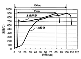
- the carbon tool steel strip having a thickness of 0.3 mm shown in Table 1 was used for preheating (invention example) and when preheating was not performed ( About the comparative example), the temperature rise curve of the carbon tool steel strip when the holding temperature of the quenching furnace was 900 ° C. was measured. The result is shown in FIG.
- the induction heating method used in the preheating furnace is based on a solenoid system. From the result of FIG. 3, it can be seen that the temperature can be raised to 600 ° C. or more within 2 seconds when the temperature rise curve of the present invention which has been preheated is seen.
- the heating time can be greatly shortened.
- the carbon tool steel strip was actually quenched and tempered using the continuous heating equipment shown in FIG.
- the preheating furnace 3 was operated in the present invention example, and no preheating was performed in the comparative example (conventional example).
- the plate passing speed was set to 7 m / min in the present invention example and 5 m / min in the comparative example.
- the quenching temperature, tempering temperature, and cooling rate were the same for both the present invention and the comparative example.
- the continuous quenching and tempering furnace for quenching and tempering the prepared carbon tool steel strip has the structure shown in FIG. 1, and the preheating furnace 3 has the structure shown in FIG.
- Unwinding the carbon tool steel strip 2 for continuous quenching and tempering by the unwinder 1 The unrolled carbon tool steel strip 2 has the same nitrogen gas atmosphere as that of the quenching heating furnace 4, and a solenoid system in which a ceramic tube 11 is disposed inside the induction heating coil 10 to keep the atmosphere is easily controlled.
- the plate was passed through the preheating furnace 3 preheated by induction heating using an induction heating device, and the temperature of the carbon tool steel strip of the present invention was raised to 650 to 700 ° C. continue,
- the carbon tool steel strip 2 was heated to the quenching temperature shown in Table 2 and passed through a quenching furnace 4 having a nitrogen gas atmosphere. Water was sprayed onto the carbon tool steel strip 2 by the spraying device 5 installed on the exit side of the quenching furnace 4 to perform the first cooling.
- the temperature of the carbon tool steel strip was about 250 ° C.
- the carbon tool steel strip 2 is restrained by four cooling surface plates 6 installed so as to sandwich the carbon tool steel strip 2, and the carbon tool steel strip 2 is quenched and quenched to about 140 ° C.
- the steel is passed through a tempering furnace 7 in a nitrogen gas atmosphere and tempered at 400 ° C., and the polishing tool 8 disposed downstream of the tempering furnace 7 is used for carbon tool steel.
- the steel strip surface is polished and the carbon tool steel strip 2 is wound up by a winder 9.
- Table 2 shows the preheating temperature and quenching temperature performed this time.
- the time of the preheating process at the time of applying the manufacturing method of this invention, a quenching process, and a tempering process was 2.5 second, 70 second, and 95 second, respectively.
- Example 1 of the present invention was collected.
- FIGS. 4 and FIG. 5 Comparative Example
- white fine carbides were observed at the base of martensite, and both were inferior.
- Table 3 shows the results of the presence or absence of decarburization, hardness, and crystal grain size. The crystal grain size is obtained by measuring prior austenite grains according to JIS0551.
- the carbon tool steel strip can be rapidly heated by a preheating furnace using induction heating, so that excellent heat treatment capability is imparted, and further, the heating time is shortened by increasing the plate passing speed, thereby improving the processing capability.
- productivity can be greatly improved.
Landscapes
- Chemical & Material Sciences (AREA)
- Engineering & Computer Science (AREA)
- Physics & Mathematics (AREA)
- Thermal Sciences (AREA)
- Crystallography & Structural Chemistry (AREA)
- Mechanical Engineering (AREA)
- Materials Engineering (AREA)
- Metallurgy (AREA)
- Organic Chemistry (AREA)
- Heat Treatment Of Strip Materials And Filament Materials (AREA)
- General Induction Heating (AREA)
- Heat Treatment Of Sheet Steel (AREA)
Abstract
炭素工具鋼鋼帯を製造するにあたり、温度制御を容易とし、熱処理能力を向上させることができる炭素工具鋼鋼帯の製造方法を提供する。巻出し機により炭素工具鋼鋼帯を巻出す巻出し工程と、前記巻出し工程により巻き出された炭素工具鋼鋼帯を通板させながら誘導加熱により予熱する予熱工程と、前記予熱工程により予熱された炭素工具鋼鋼帯を850℃を超 え1100℃以下に加熱された不活性ガス雰囲気中に通板し、次いで急冷して焼入れする焼入れ工程と、前記焼入れ工程により焼入れした炭素工具鋼鋼帯を300~450℃に加熱された不活性ガス雰囲気中に通板して焼戻しする焼戻し工程と、前記焼戻し工程により焼戻した炭素工具鋼鋼帯を巻取る巻取り工程とを連続して行う炭素工具鋼鋼帯の製造方法。
Description
本発明は、炭素工具鋼鋼帯の製造方法に関するものである。
例えば、バネや弁等に用いるのに適した炭素工具鋼の鋼帯(以下「炭素工具鋼鋼帯」という。)は、一般に、所定の板厚まで圧延を行った後、予熱帯と加熱帯を有する焼入れ炉、噴霧装置、水冷定盤および焼戻し炉をこの順番で連続的に配置した連続加熱設備を利用して、炭素工具鋼鋼帯を巻出しながら連続的に焼入れと焼戻しを行う方法により製造されている。
前述の炭素工具鋼鋼帯に連続加熱設備を利用して焼入れ焼戻しを行う具体的な製造方法には、例えば、本出願人による特開昭56-139627号公報(特許文献1)に記載された製造方法がある。この製造方法は、焼入れ炉を出た炭素工具鋼鋼帯を急冷し焼入を行なう場合に、炭素工具鋼鋼帯のきず及び歪の発生を防止し、焼入後の硬さのばらつきを少なくすることができるものである。
このような連続加熱設備には、熱源として天然ガス、軽油、重油等をバーナで燃焼させた燃焼熱を利用するものや、電気ヒーター等の通電加熱により発生した熱を利用するものなどがある。いずれの場合も、炭素工具鋼鋼帯は、これらの熱源からの輻射熱により加熱されるのであり、炭素工具鋼鋼帯への伝熱は主として輻射加熱によるものであった。
また、従来技術に係る連続加熱設備のうち、焼入れ炉は、一般に炭素工具鋼鋼帯が通板される部分に複数の均熱帯を連続的に設けた構成となっている。均熱帯の一般的な構成としては、例えば、炭素工具鋼鋼帯を一定の温度まで予熱する予熱帯と、炭素工具鋼鋼帯の所定の焼入れ温度に保持する1または2以上の加熱帯とからなっている。このような構成により、初めに常温で巻き出され、焼入れ炉に通板された炭素工具鋼鋼帯を、焼入れ温度まで昇温させることができる。
前述の炭素工具鋼鋼帯に連続加熱設備を利用して焼入れ焼戻しを行う具体的な製造方法には、例えば、本出願人による特開昭56-139627号公報(特許文献1)に記載された製造方法がある。この製造方法は、焼入れ炉を出た炭素工具鋼鋼帯を急冷し焼入を行なう場合に、炭素工具鋼鋼帯のきず及び歪の発生を防止し、焼入後の硬さのばらつきを少なくすることができるものである。
このような連続加熱設備には、熱源として天然ガス、軽油、重油等をバーナで燃焼させた燃焼熱を利用するものや、電気ヒーター等の通電加熱により発生した熱を利用するものなどがある。いずれの場合も、炭素工具鋼鋼帯は、これらの熱源からの輻射熱により加熱されるのであり、炭素工具鋼鋼帯への伝熱は主として輻射加熱によるものであった。
また、従来技術に係る連続加熱設備のうち、焼入れ炉は、一般に炭素工具鋼鋼帯が通板される部分に複数の均熱帯を連続的に設けた構成となっている。均熱帯の一般的な構成としては、例えば、炭素工具鋼鋼帯を一定の温度まで予熱する予熱帯と、炭素工具鋼鋼帯の所定の焼入れ温度に保持する1または2以上の加熱帯とからなっている。このような構成により、初めに常温で巻き出され、焼入れ炉に通板された炭素工具鋼鋼帯を、焼入れ温度まで昇温させることができる。
本発明者らは上述した特許文献1に記載された連続加熱設備を用いて、炭素工具鋼鋼帯への熱処理能力を向上させ、生産能力を向上させる方法を検討した。
単位時間あたりの熱処理能力を向上させるには、例えば、焼入れ炉の長さを延長すると共に通板速度を早くする方法など、が考えられる。
しかしながら、従来の輻射加熱では、焼入れ炉を構成する複数の均熱帯のうち予熱帯の温度域における炭素工具鋼鋼帯の昇温速度が遅いために、熱処理能力の向上には十分な効果が得られないという問題がある。また、輻射加熱だと、上記の温度域における炭素工具鋼鋼帯の昇温速度その他の温度条件を任意の条件に制御することが容易ではないという問題もある。
本発明の目的は、炭素工具鋼鋼帯を製造するにあたり、温度制御を容易とし、熱処理能力を向上させることができる炭素工具鋼鋼帯の製造方法を提供するものである。
単位時間あたりの熱処理能力を向上させるには、例えば、焼入れ炉の長さを延長すると共に通板速度を早くする方法など、が考えられる。
しかしながら、従来の輻射加熱では、焼入れ炉を構成する複数の均熱帯のうち予熱帯の温度域における炭素工具鋼鋼帯の昇温速度が遅いために、熱処理能力の向上には十分な効果が得られないという問題がある。また、輻射加熱だと、上記の温度域における炭素工具鋼鋼帯の昇温速度その他の温度条件を任意の条件に制御することが容易ではないという問題もある。
本発明の目的は、炭素工具鋼鋼帯を製造するにあたり、温度制御を容易とし、熱処理能力を向上させることができる炭素工具鋼鋼帯の製造方法を提供するものである。
本発明は、上述した課題に鑑みてなされたものである。
すなわち本発明は、
(1)巻出し機により炭素工具鋼鋼帯を巻出す巻出し工程と、
(2)前記巻出し工程により巻き出された炭素工具鋼鋼帯を通板させながら誘導加熱により予熱する予熱工程と、
(3)前記予熱工程により予熱された炭素工具鋼鋼帯を850℃を超え1100℃以下に加熱された不活性ガス雰囲気中に通板し、次いで急冷して焼入れする焼入れ工程と、
(4)前記焼入れ工程により焼入れした炭素工具鋼鋼帯を300~450℃に加熱された不活性ガス雰囲気中に通板して焼戻しする焼戻し工程と、
(5)前記焼戻し工程により焼戻した炭素工具鋼鋼帯を巻取る巻取り工程と、
を連続して行う炭素工具鋼鋼帯の製造方法である。
すなわち本発明は、
(1)巻出し機により炭素工具鋼鋼帯を巻出す巻出し工程と、
(2)前記巻出し工程により巻き出された炭素工具鋼鋼帯を通板させながら誘導加熱により予熱する予熱工程と、
(3)前記予熱工程により予熱された炭素工具鋼鋼帯を850℃を超え1100℃以下に加熱された不活性ガス雰囲気中に通板し、次いで急冷して焼入れする焼入れ工程と、
(4)前記焼入れ工程により焼入れした炭素工具鋼鋼帯を300~450℃に加熱された不活性ガス雰囲気中に通板して焼戻しする焼戻し工程と、
(5)前記焼戻し工程により焼戻した炭素工具鋼鋼帯を巻取る巻取り工程と、
を連続して行う炭素工具鋼鋼帯の製造方法である。
好ましくは、前記予熱工程の温度が600~750℃である炭素工具鋼鋼帯の製造方法である。
また、本発明では、前記の焼入れ工程の急冷は、200~350℃に冷却する第一冷却工程の後、水冷定盤内で炭素工具鋼鋼帯を拘束しつつMs点以下に冷却する第二冷却工程を設けることが好ましく、更に好ましくは、前記第二冷却工程において、炭素工具鋼鋼帯を拘束する前記水冷定盤を複数個とすることが好ましい。
また、本発明では、前記焼戻し工程と前記巻取り工程の間に、更に焼戻した炭素工具鋼鋼帯表面を研磨する研磨工程を設けることが好ましい。
前記予熱工程において、誘導加熱は誘導加熱コイルの内側にセラミックス管を配置した前記焼入れ工程と同一雰囲気中の誘導加熱帯により、行うことが好ましい。
また、本発明では、前記の焼入れ工程の急冷は、200~350℃に冷却する第一冷却工程の後、水冷定盤内で炭素工具鋼鋼帯を拘束しつつMs点以下に冷却する第二冷却工程を設けることが好ましく、更に好ましくは、前記第二冷却工程において、炭素工具鋼鋼帯を拘束する前記水冷定盤を複数個とすることが好ましい。
また、本発明では、前記焼戻し工程と前記巻取り工程の間に、更に焼戻した炭素工具鋼鋼帯表面を研磨する研磨工程を設けることが好ましい。
前記予熱工程において、誘導加熱は誘導加熱コイルの内側にセラミックス管を配置した前記焼入れ工程と同一雰囲気中の誘導加熱帯により、行うことが好ましい。
本発明によれば、誘導加熱を利用した予熱炉によって炭素工具鋼鋼帯を急速加熱できることから、温度制御が容易となり優れた熱処理能力が得られ、更に、加熱時間が短縮され、熱処理能力が向上することで生産性も大きく向上させることができる。また、予熱炉、加熱炉を不活性ガス雰囲気とすることで確実に脱炭を防止し、所望の硬さをより確実に得ることができる。
本発明の製造方法の特徴は、炭素工具鋼鋼帯を焼入れ温度にまで昇温する際に、焼入れ炉の予熱帯のみによって昇温を行うのではなく、焼入れ炉の前に誘導加熱を利用した予熱炉を設置し、この予熱炉により昇温を行うことにより、炭素工具鋼鋼帯を急速加熱できることである。また、焼入れと焼戻し時の雰囲気を不活性ガス雰囲気とすることで脱炭を発生させることなく所望の硬さを得ることができる。
以下、本発明について説明する。
先ず、本発明で用いる炭素工具鋼鋼帯は、JIS-G-3311(みがき特殊帯鋼)で規定される炭素工具鋼の組成を有するものであればよい。好ましい組成は、質量%でC:0.8~1.2%、Si:0.1~0.35%、Mn:0.1~0.5%、Cr:0.05~0.3%を含有し、残部はFe及び不純物である。
以下、本発明について説明する。
先ず、本発明で用いる炭素工具鋼鋼帯は、JIS-G-3311(みがき特殊帯鋼)で規定される炭素工具鋼の組成を有するものであればよい。好ましい組成は、質量%でC:0.8~1.2%、Si:0.1~0.35%、Mn:0.1~0.5%、Cr:0.05~0.3%を含有し、残部はFe及び不純物である。
図1に本発明で用いる連続加熱設備のレイアウトの一例を示す。図1を示しながら本発明を説明する。
焼入れと焼戻しを連続で行うための炭素工具鋼鋼帯2を巻出し機1により巻き出す(巻出し工程)。続いて、巻き出された炭素工具鋼鋼帯2は、誘導加熱を利用した予熱炉3に通板される(予熱工程)。
本発明において誘導加熱を利用した予熱炉によって予熱を行う理由は、交番磁束によって炭素工具鋼鋼帯2に誘起される渦電流のジュール熱によって炭素工具鋼鋼帯2が自ら発熱するので、輻射加熱により加熱する場合に比べて急速に加熱することが可能となるためである。誘導加熱の方法としては、例えば、ソレノイド方式とトランスバース方式等があるが、本発明の場合では、ソレノイド方式とするのが好ましい。これは、ソレノイド方式の場合、炭素工具鋼鋼帯2のAc1点を利用して、炭素工具鋼鋼帯の温度制御を容易とし、炭素工具鋼鋼帯を均一に加熱しやすいためである。
この予熱工程での予熱温度の下限は600℃以上の範囲が好ましい。これは、炭素工具鋼鋼帯の予熱温度が600℃未満であると、予熱工程の後に行う焼入れ温度まで炭素工具鋼鋼帯を加熱することが困難となる場合があるからである。そうなると、十分な焼入れ硬さを得ることができなくなる。また、予熱温度の上限は750℃とするのが好ましい。これは、高周波加熱によって750℃を超える温度に急速加熱する炭素工具鋼鋼帯の変形のおそれがあるためである。また、750℃付近の炭素工具鋼鋼帯のAc1点の温度を超えることにより金属組織がフェライトからオーステナイトに変態する。オーステナイトは非磁性であり、ソレノイド方式の高周波加熱ではAc1点の温度以上で加熱効率が低下して過熱が防止されるため、予熱工程における炭素工具鋼鋼帯の温度制御を行うのに好都合である。
また、予熱炉内では炭素工具鋼鋼帯表面の脱炭を防止するために後述する焼入れ工程と同一な不活性ガス雰囲気とし、誘導加熱コイル10の内側には雰囲気を保つためにセラミックス管11を配置して、炭素工具鋼鋼帯2を前記セラミックス管11内を通板させることが好ましい。セラミックス管11は非磁性体であり、誘導加熱が生じないため、電力をロスすることなく効率的に炭素工具鋼鋼帯を誘導加熱することができる。セラミックス管は放熱による熱損失を低減するために、セラミックス管を断熱材で被覆することが好ましい。
なお、予熱工程における通板速度が過度に速すぎると、上述した予熱効果が得られない。そのため、通板速度を調整し、炭素工具鋼鋼帯のある部位が予熱炉を通過するのに要する時間を0.8~3秒の範囲となるように通板させるのが好ましい。
焼入れと焼戻しを連続で行うための炭素工具鋼鋼帯2を巻出し機1により巻き出す(巻出し工程)。続いて、巻き出された炭素工具鋼鋼帯2は、誘導加熱を利用した予熱炉3に通板される(予熱工程)。
本発明において誘導加熱を利用した予熱炉によって予熱を行う理由は、交番磁束によって炭素工具鋼鋼帯2に誘起される渦電流のジュール熱によって炭素工具鋼鋼帯2が自ら発熱するので、輻射加熱により加熱する場合に比べて急速に加熱することが可能となるためである。誘導加熱の方法としては、例えば、ソレノイド方式とトランスバース方式等があるが、本発明の場合では、ソレノイド方式とするのが好ましい。これは、ソレノイド方式の場合、炭素工具鋼鋼帯2のAc1点を利用して、炭素工具鋼鋼帯の温度制御を容易とし、炭素工具鋼鋼帯を均一に加熱しやすいためである。
この予熱工程での予熱温度の下限は600℃以上の範囲が好ましい。これは、炭素工具鋼鋼帯の予熱温度が600℃未満であると、予熱工程の後に行う焼入れ温度まで炭素工具鋼鋼帯を加熱することが困難となる場合があるからである。そうなると、十分な焼入れ硬さを得ることができなくなる。また、予熱温度の上限は750℃とするのが好ましい。これは、高周波加熱によって750℃を超える温度に急速加熱する炭素工具鋼鋼帯の変形のおそれがあるためである。また、750℃付近の炭素工具鋼鋼帯のAc1点の温度を超えることにより金属組織がフェライトからオーステナイトに変態する。オーステナイトは非磁性であり、ソレノイド方式の高周波加熱ではAc1点の温度以上で加熱効率が低下して過熱が防止されるため、予熱工程における炭素工具鋼鋼帯の温度制御を行うのに好都合である。
また、予熱炉内では炭素工具鋼鋼帯表面の脱炭を防止するために後述する焼入れ工程と同一な不活性ガス雰囲気とし、誘導加熱コイル10の内側には雰囲気を保つためにセラミックス管11を配置して、炭素工具鋼鋼帯2を前記セラミックス管11内を通板させることが好ましい。セラミックス管11は非磁性体であり、誘導加熱が生じないため、電力をロスすることなく効率的に炭素工具鋼鋼帯を誘導加熱することができる。セラミックス管は放熱による熱損失を低減するために、セラミックス管を断熱材で被覆することが好ましい。
なお、予熱工程における通板速度が過度に速すぎると、上述した予熱効果が得られない。そのため、通板速度を調整し、炭素工具鋼鋼帯のある部位が予熱炉を通過するのに要する時間を0.8~3秒の範囲となるように通板させるのが好ましい。
上述の予熱工程の後、炭素工具鋼鋼帯2は脱炭を防ぐために不活性ガス雰囲気とした焼入れ加熱炉4に通板し、850℃を超え1100℃以下に昇温保持する(焼入れ工程)。好適な不活性ガスとしては、窒素、アルゴン、アンモニア分解ガス等があるが、中でも窒素は入手のし易さや安価であることから窒素ガスを用いるのが好ましい。
本発明において、焼入れ加熱温度が850℃以下であると炭化物の固溶が不十分となって疲労特性が低減する。また、焼入れ加熱温度が1100℃を超えると炭化物の固溶量が多くなり、焼戻し時に硬さが高くなりにくくなるばかりか、残留炭化物が少なくなり、打抜き性が劣化する。そのため、焼入れ加熱温度の範囲を850℃を超え1100℃以下とする。
なお、焼入れ工程における通板速度が過度に速すぎると、上述した焼入れ時の加熱温度の効果が得られない。そのため、通板速度を調整し、炭素工具鋼鋼帯のある部位が焼入れ炉を追加するのに要する時間を35~90秒の範囲となるように通板させるのが好ましい。
続いて、炭素工具鋼鋼帯2を急冷して焼入れを行う。急冷の方法としては、ソルトバス、溶融金属を用いる方法もあるが、水を噴射する方法を用いるのが最も簡便な方法であると共に、炭素工具鋼鋼帯表面に薄い酸化被膜を形成させることができる。この薄い酸化被膜は硬質であり、後述する水冷定盤6を通板する際に、炭素工具鋼鋼帯表面のきずの発生を抑制できる。そのため、本発明で用いる炭素工具鋼鋼帯2への急冷も水を噴射する方法を用いるのが好ましい。
本発明において、焼入れ加熱温度が850℃以下であると炭化物の固溶が不十分となって疲労特性が低減する。また、焼入れ加熱温度が1100℃を超えると炭化物の固溶量が多くなり、焼戻し時に硬さが高くなりにくくなるばかりか、残留炭化物が少なくなり、打抜き性が劣化する。そのため、焼入れ加熱温度の範囲を850℃を超え1100℃以下とする。
なお、焼入れ工程における通板速度が過度に速すぎると、上述した焼入れ時の加熱温度の効果が得られない。そのため、通板速度を調整し、炭素工具鋼鋼帯のある部位が焼入れ炉を追加するのに要する時間を35~90秒の範囲となるように通板させるのが好ましい。
続いて、炭素工具鋼鋼帯2を急冷して焼入れを行う。急冷の方法としては、ソルトバス、溶融金属を用いる方法もあるが、水を噴射する方法を用いるのが最も簡便な方法であると共に、炭素工具鋼鋼帯表面に薄い酸化被膜を形成させることができる。この薄い酸化被膜は硬質であり、後述する水冷定盤6を通板する際に、炭素工具鋼鋼帯表面のきずの発生を抑制できる。そのため、本発明で用いる炭素工具鋼鋼帯2への急冷も水を噴射する方法を用いるのが好ましい。
本発明で前述の水を噴射して急冷するには、焼入れ炉4の出側に設置された噴霧装置5を設けるのが好ましい。
また、焼入れ工程の急冷は、圧縮空気と浄水を用いた噴霧装置5によって炭素工具鋼鋼帯2を200~350℃に冷却する第一冷却工程の後、炭素工具鋼鋼帯を挟みこむように水冷定盤内6で拘束し、形状を矯正しながらMs点以下に冷却する第二冷却工程を行ってマルテンサイト組織とするのが好ましい。
冷却を二段階とするのは、第一冷却工程でパーライトノーズを避けつつ、且つ、炭素工具鋼鋼帯2の焼入れ時に生じる歪を軽減し、次の第二冷却工程中でマルテンサイト変態を行わせつつ、炭素工具鋼鋼帯2の形状を整えることができるためである。
前述の第一冷却工程において、炭素工具鋼鋼帯2の急冷の下限をMs点を超える温度としたのは、炭素工具鋼鋼帯2の焼入れ時に生じる歪を軽減させるためである。これは、第一の冷却工程で一気にMs点以下とすると、焼入れ時の歪が大きくなり過ぎて形状が不安定になる場合があるためである。なお、炭素工具鋼鋼帯の組成によっても若干Ms点は変化するが、おおよそ180~190℃である。好ましい第一冷却工程の冷却温度の下限はMs点よりも10~20℃高めの温度とすると良い。また、第一冷却工程の冷却温度の上限を350℃としたのは、350℃を超える温度となると、後述する水冷定盤内でMs点以下まで冷却するのが困難となる場合があるためである。伝熱には熱伝導、熱対流、輻射熱の3つの形態があるが、水冷定盤中6で炭素工具鋼鋼帯2を拘束しつつMs点以下に冷却を行うと、水冷定盤内で水冷定盤6と炭素工具鋼鋼帯2との物理的接触による熱伝導により急速に冷却される。そして、炭素工具鋼鋼帯2を水冷定盤6によって拘束することが可能となるため、炭素工具鋼鋼帯2の変形を防止したり、変形を矯正できるためである。
本発明で用いる水冷定盤6は水により冷却しつつ、更に、複数個を連続して配置することが好ましい。これは、水冷定盤内で拘束する時間が長くすることができるため、より確実にMs点以下まで冷却することができるため、炭素工具鋼鋼帯2の変形の防止や矯正をより確実に行うことができるためである。
また、焼入れ工程の急冷は、圧縮空気と浄水を用いた噴霧装置5によって炭素工具鋼鋼帯2を200~350℃に冷却する第一冷却工程の後、炭素工具鋼鋼帯を挟みこむように水冷定盤内6で拘束し、形状を矯正しながらMs点以下に冷却する第二冷却工程を行ってマルテンサイト組織とするのが好ましい。
冷却を二段階とするのは、第一冷却工程でパーライトノーズを避けつつ、且つ、炭素工具鋼鋼帯2の焼入れ時に生じる歪を軽減し、次の第二冷却工程中でマルテンサイト変態を行わせつつ、炭素工具鋼鋼帯2の形状を整えることができるためである。
前述の第一冷却工程において、炭素工具鋼鋼帯2の急冷の下限をMs点を超える温度としたのは、炭素工具鋼鋼帯2の焼入れ時に生じる歪を軽減させるためである。これは、第一の冷却工程で一気にMs点以下とすると、焼入れ時の歪が大きくなり過ぎて形状が不安定になる場合があるためである。なお、炭素工具鋼鋼帯の組成によっても若干Ms点は変化するが、おおよそ180~190℃である。好ましい第一冷却工程の冷却温度の下限はMs点よりも10~20℃高めの温度とすると良い。また、第一冷却工程の冷却温度の上限を350℃としたのは、350℃を超える温度となると、後述する水冷定盤内でMs点以下まで冷却するのが困難となる場合があるためである。伝熱には熱伝導、熱対流、輻射熱の3つの形態があるが、水冷定盤中6で炭素工具鋼鋼帯2を拘束しつつMs点以下に冷却を行うと、水冷定盤内で水冷定盤6と炭素工具鋼鋼帯2との物理的接触による熱伝導により急速に冷却される。そして、炭素工具鋼鋼帯2を水冷定盤6によって拘束することが可能となるため、炭素工具鋼鋼帯2の変形を防止したり、変形を矯正できるためである。
本発明で用いる水冷定盤6は水により冷却しつつ、更に、複数個を連続して配置することが好ましい。これは、水冷定盤内で拘束する時間が長くすることができるため、より確実にMs点以下まで冷却することができるため、炭素工具鋼鋼帯2の変形の防止や矯正をより確実に行うことができるためである。
前述の焼入れ工程に続き、炭素工具鋼鋼帯2を300~450℃に加熱して、不活性ガス雰囲気の焼戻し炉7に通板して焼戻しを行う。不活性ガス雰囲気とするのは炭素工具鋼鋼帯の脱炭を防ぐためである。
本発明において、焼戻しの温度が300℃未満であると、硬度が高くなり過ぎる。一方、焼戻しの温度が450℃より高いと硬度が低くなる。
従って焼戻し温度が高過ぎても、低過ぎても適切な硬さを得ることができず、打抜き性が阻害されることになる。なお、焼戻しで調整する硬さはビッカース硬度が500~650(Hv)とすれば、良好な打抜き性を得ることができる。
なお、焼戻し工程における通板速度が過度に速すぎると、上述した焼戻し時の加熱温度の効果が得られない。そのため、通板速度を調整し、炭素工具鋼鋼帯が焼戻し炉を通過するのに要する時間を50~125秒の範囲となるように通板させるのが好ましい。
本発明において、焼戻しの温度が300℃未満であると、硬度が高くなり過ぎる。一方、焼戻しの温度が450℃より高いと硬度が低くなる。
従って焼戻し温度が高過ぎても、低過ぎても適切な硬さを得ることができず、打抜き性が阻害されることになる。なお、焼戻しで調整する硬さはビッカース硬度が500~650(Hv)とすれば、良好な打抜き性を得ることができる。
なお、焼戻し工程における通板速度が過度に速すぎると、上述した焼戻し時の加熱温度の効果が得られない。そのため、通板速度を調整し、炭素工具鋼鋼帯が焼戻し炉を通過するのに要する時間を50~125秒の範囲となるように通板させるのが好ましい。
前述の焼戻し工程により焼戻した炭素工具鋼鋼帯2は、焼戻し炉7の下流側に配置された研磨装置8によって、炭素工具鋼鋼帯表面を研磨するのが好ましい。
これは、前述したように、焼入れ時に形成された酸化被膜を除去するほか、表面に不可避的に付いたきずを除去または軽減することで、表面のきずに起因した疲労破壊を防止することができる。
その後、巻取り機9によって巻取る(巻取り工程)ことにより、脱炭を発生させることなく所望の硬さを有する炭素工具鋼鋼帯を得ることができる。
本発明では、前述したように、巻出し工程から巻取り工程までの各工程をコイルから巻き出した炭素工具鋼鋼帯を再びコイルに巻き取るまでを連続で行うことが可能なため、高い生産性を有するものである。これに加え、誘導加熱を利用した予熱炉によって、炭素工具鋼鋼帯を急速加熱できることから、優れた熱処理能力を付与し、更に、加熱時間を短縮し、処理能力を向上させることで生産性も大きく向上させることができる。
これは、前述したように、焼入れ時に形成された酸化被膜を除去するほか、表面に不可避的に付いたきずを除去または軽減することで、表面のきずに起因した疲労破壊を防止することができる。
その後、巻取り機9によって巻取る(巻取り工程)ことにより、脱炭を発生させることなく所望の硬さを有する炭素工具鋼鋼帯を得ることができる。
本発明では、前述したように、巻出し工程から巻取り工程までの各工程をコイルから巻き出した炭素工具鋼鋼帯を再びコイルに巻き取るまでを連続で行うことが可能なため、高い生産性を有するものである。これに加え、誘導加熱を利用した予熱炉によって、炭素工具鋼鋼帯を急速加熱できることから、優れた熱処理能力を付与し、更に、加熱時間を短縮し、処理能力を向上させることで生産性も大きく向上させることができる。
先ず、予熱炉の効果を確認するため、表1に示す厚さが0.3mmの炭素工具鋼鋼帯を使用して、予熱を行った場合(本発明例)と予熱を行わなかった場合(比較例)について、焼入れ炉の保持温度を900℃としたときの炭素工具鋼鋼帯の温度上昇曲線を測定した。その結果を図3に示す。なお、予熱炉で用いた誘導加熱の方法は、ソレノイド方式によるものである。
図3の結果から、予熱を行った本発明の温度上昇曲線を見ると、2秒以内で600℃以上まで昇温できていることが分かる。また、予熱を行った場合は、炭素工具鋼鋼帯が900℃に達する時間は75秒であるのに対し、予熱を行わなかった場合は100秒の時間を要することから、本発明の製造方法によれば大幅に加熱時間の短縮が行えることが分かった。
次に、実際に図1に示す連続加熱設備を用いて、炭素工具鋼鋼帯を連続して焼入れ、焼戻しした。このとき、本発明例では予熱炉3を稼働させ、比較例(従来例)では予熱なしとした。また、前記の予備実験結果をもとに、通板速度は本発明例が7m/分とし、比較例を5m/分とした。焼入れ温度、焼戻し温度、冷却速度は本発明と比較例ともに同じとした。
図3の結果から、予熱を行った本発明の温度上昇曲線を見ると、2秒以内で600℃以上まで昇温できていることが分かる。また、予熱を行った場合は、炭素工具鋼鋼帯が900℃に達する時間は75秒であるのに対し、予熱を行わなかった場合は100秒の時間を要することから、本発明の製造方法によれば大幅に加熱時間の短縮が行えることが分かった。
次に、実際に図1に示す連続加熱設備を用いて、炭素工具鋼鋼帯を連続して焼入れ、焼戻しした。このとき、本発明例では予熱炉3を稼働させ、比較例(従来例)では予熱なしとした。また、前記の予備実験結果をもとに、通板速度は本発明例が7m/分とし、比較例を5m/分とした。焼入れ温度、焼戻し温度、冷却速度は本発明と比較例ともに同じとした。
厚さが0.3mm、長さが約1500mの表1に示す炭素工具鋼鋼帯を用意した。用意した炭素工具鋼鋼帯を焼入れ、焼戻しする連続焼入れ焼戻し炉は図1に示す構造のものであり、予熱炉3は図2に示す構造のものである。具体的には、
焼入れと焼戻しを連続で行うための炭素工具鋼鋼帯2を巻出し機1により巻き出して、続いて、
巻き出された炭素工具鋼鋼帯2は、焼入れ加熱炉4と同じ窒素ガス雰囲気とし、誘導加熱コイル10の内側には雰囲気を保つためにセラミックス管11を配置した温度制御が容易なソレノイド方式の誘導加熱装置による誘導加熱により予熱された予熱炉3に通板させ、本発明の炭素工具鋼鋼帯を650~700℃に昇温させた。続いて、
炭素工具鋼鋼帯2を表2に示す焼入れ温度に昇温保持し、窒素ガス雰囲気とした焼入れ加熱炉4中を通板させ、続いて、
焼入れ炉4の出側に設置された噴霧装置5により、炭素工具鋼鋼帯2に水を噴射して最初の冷却を行った。炭素工具鋼鋼帯の温度は250℃程度あった。更に、炭素工具鋼鋼帯2を挟みこむように設置された4個の冷却定盤内6で拘束して炭素工具鋼鋼帯2を約140℃まで急冷して焼入れを行い、続いて、
炭素工具鋼鋼帯2の脱炭を防ぐために窒素ガス雰囲気とした焼戻し炉7に通板して400℃で焼戻しを行い、焼戻し炉7の下流側に配置された研磨装置8によって、炭素工具鋼鋼帯表面を研磨して、巻取り機9によって炭素工具鋼鋼帯2を巻取る構造を有するものである。
今回行った予熱温度、焼入れ温度を併せて表2に示す。なお、本発明の製造方法を適用した際の予熱工程、焼入れ工程、焼戻し工程の時間は、それぞれ2.5秒、70秒、95秒であった。
焼入れと焼戻しを連続で行うための炭素工具鋼鋼帯2を巻出し機1により巻き出して、続いて、
巻き出された炭素工具鋼鋼帯2は、焼入れ加熱炉4と同じ窒素ガス雰囲気とし、誘導加熱コイル10の内側には雰囲気を保つためにセラミックス管11を配置した温度制御が容易なソレノイド方式の誘導加熱装置による誘導加熱により予熱された予熱炉3に通板させ、本発明の炭素工具鋼鋼帯を650~700℃に昇温させた。続いて、
炭素工具鋼鋼帯2を表2に示す焼入れ温度に昇温保持し、窒素ガス雰囲気とした焼入れ加熱炉4中を通板させ、続いて、
焼入れ炉4の出側に設置された噴霧装置5により、炭素工具鋼鋼帯2に水を噴射して最初の冷却を行った。炭素工具鋼鋼帯の温度は250℃程度あった。更に、炭素工具鋼鋼帯2を挟みこむように設置された4個の冷却定盤内6で拘束して炭素工具鋼鋼帯2を約140℃まで急冷して焼入れを行い、続いて、
炭素工具鋼鋼帯2の脱炭を防ぐために窒素ガス雰囲気とした焼戻し炉7に通板して400℃で焼戻しを行い、焼戻し炉7の下流側に配置された研磨装置8によって、炭素工具鋼鋼帯表面を研磨して、巻取り機9によって炭素工具鋼鋼帯2を巻取る構造を有するものである。
今回行った予熱温度、焼入れ温度を併せて表2に示す。なお、本発明の製造方法を適用した際の予熱工程、焼入れ工程、焼戻し工程の時間は、それぞれ2.5秒、70秒、95秒であった。


焼入れと焼戻しを行った炭素工具鋼鋼帯から、脱炭の有無、硬さ、金属組織を調査するため、それぞれの試験片を採取した。代表的な金属組織として、本発明例1、比較例の顕微鏡写真を図4及び図5に示す。
図4(本発明例1)及び図5(比較例)の金属組織は、マルテンサイトの基地に白色の微細炭化物が認められ、両者ともに遜色のないものであった。脱炭の有無、硬さ、結晶粒度の結果は併せて表3に示す。なお、結晶粒度は旧オーステナイト粒をJIS0551に従って測定したものである。
図4(本発明例1)及び図5(比較例)の金属組織は、マルテンサイトの基地に白色の微細炭化物が認められ、両者ともに遜色のないものであった。脱炭の有無、硬さ、結晶粒度の結果は併せて表3に示す。なお、結晶粒度は旧オーステナイト粒をJIS0551に従って測定したものである。
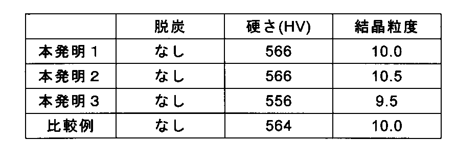
以上の結果から、本発明では、従来から実施されていた連続焼入れ、焼戻しを行った炭素工具鋼鋼帯が有する各種の特性を維持していることが分かる。また、今回の実施例では、本発明を適用した場合の所要時間は約214分であるのに対し、比較例では約300分であった。
従って、誘導加熱を利用した予熱炉によって、炭素工具鋼鋼帯を急速加熱できることから、優れた熱処理能力を付与し、更に、通板速度を高めることで加熱時間を短縮し、処理能力を向上させることで生産性も大きく向上させることができるものである。
従って、誘導加熱を利用した予熱炉によって、炭素工具鋼鋼帯を急速加熱できることから、優れた熱処理能力を付与し、更に、通板速度を高めることで加熱時間を短縮し、処理能力を向上させることで生産性も大きく向上させることができるものである。
1 巻出し機
2 炭素工具鋼鋼帯
3 予熱炉
4 焼入れ炉
5 噴霧装置
6 水冷定盤
7 焼戻し炉
8 研磨装置
9 巻取り機
10 誘導加熱コイル
11 セラミックス管
2 炭素工具鋼鋼帯
3 予熱炉
4 焼入れ炉
5 噴霧装置
6 水冷定盤
7 焼戻し炉
8 研磨装置
9 巻取り機
10 誘導加熱コイル
11 セラミックス管
Claims (6)
- (1)巻出し機により炭素工具鋼鋼帯を巻出す巻出し工程と、
(2)前記巻出し工程により巻き出された炭素工具鋼鋼帯を通板させながら誘導加熱により予熱する予熱工程と、
(3)前記予熱工程により予熱された炭素工具鋼鋼帯を850℃を超え1100℃以下に加熱された不活性ガス雰囲気中に通板し、次いで急冷して焼入れする焼入れ工程と、
(4)前記焼入れ工程により焼入れした炭素工具鋼鋼帯を300~450℃に加熱された不活性ガス雰囲気中に通板して焼戻しする焼戻し工程と、
(5)前記焼戻し工程により焼戻した炭素工具鋼鋼帯を巻取る巻取り工程と、
を連続して行うことを特徴とする炭素工具鋼鋼帯の製造方法。 - 前記予熱工程の温度が600~750℃であることを特徴とする請求項1に記載の炭素工具鋼鋼帯の製造方法。
- 前記焼入れ工程の急冷は、Ms点を超えて350℃以下に冷却する第一冷却工程の後、
水冷定盤で炭素工具鋼鋼帯を拘束しつつMs点以下に冷却する第二冷却工程を設けることを特徴とする請求項1または2に記載の炭素工具鋼鋼帯の製造方法。 - 前記第二冷却工程において、炭素工具鋼鋼帯を拘束する前記水冷定盤が複数個であることを特徴とする請求項3に記載の炭素工具鋼鋼帯の製造方法。
- 前記焼戻し工程と前記巻取り工程の間に、更に、焼戻した炭素工具鋼鋼帯表面を研磨する研磨工程を設けることを特徴とする請求項1乃至4の何れかに記載の炭素工具鋼鋼帯の製造方法。
- 前記予熱工程において、誘導加熱は誘導加熱コイルの内側にセラミックス管を配置した前記焼入れ工程と同一雰囲気中の誘導加熱帯により、行うことを特徴とする請求項1乃至5の何れかに記載の炭素工具鋼鋼帯の製造方法。
Priority Applications (1)
| Application Number | Priority Date | Filing Date | Title |
|---|---|---|---|
| JP2013534508A JP5534492B2 (ja) | 2012-03-29 | 2013-03-29 | 炭素工具鋼鋼帯の製造方法 |
Applications Claiming Priority (2)
| Application Number | Priority Date | Filing Date | Title |
|---|---|---|---|
| JP2012075464 | 2012-03-29 | ||
| JP2012-075464 | 2012-03-29 |
Publications (1)
| Publication Number | Publication Date |
|---|---|
| WO2013147155A1 true WO2013147155A1 (ja) | 2013-10-03 |
Family
ID=49260397
Family Applications (1)
| Application Number | Title | Priority Date | Filing Date |
|---|---|---|---|
| PCT/JP2013/059519 Ceased WO2013147155A1 (ja) | 2012-03-29 | 2013-03-29 | 炭素工具鋼鋼帯の製造方法 |
Country Status (2)
| Country | Link |
|---|---|
| JP (1) | JP5534492B2 (ja) |
| WO (1) | WO2013147155A1 (ja) |
Cited By (4)
| Publication number | Priority date | Publication date | Assignee | Title |
|---|---|---|---|---|
| JP2015067873A (ja) * | 2013-09-30 | 2015-04-13 | 日立金属株式会社 | マルテンサイト系ステンレス鋼鋼帯の製造方法 |
| WO2017153826A1 (en) * | 2016-03-10 | 2017-09-14 | Tata Steel Limited | A method for heat treating an iron-carbon alloy |
| JP2018111881A (ja) * | 2017-01-12 | 2018-07-19 | 日立金属株式会社 | マルテンサイト系ステンレス鋼帯の製造方法 |
| CN109618441A (zh) * | 2018-11-19 | 2019-04-12 | 安徽东升精密铸钢件有限公司 | 一种应用于轨链组件生产的加热装置 |
Citations (6)
| Publication number | Priority date | Publication date | Assignee | Title |
|---|---|---|---|---|
| JPS53133513A (en) * | 1977-04-27 | 1978-11-21 | Nippon Steel Corp | Operating method for continuous heat treatment furnace |
| JPS56139627A (en) * | 1981-01-30 | 1981-10-31 | Hitachi Metals Ltd | Fog quenching device for striplike steel |
| JPS6215564U (ja) * | 1985-07-11 | 1987-01-30 | ||
| JPH06128648A (ja) * | 1992-10-19 | 1994-05-10 | Daido Steel Co Ltd | 焼入鋼帯の製造方法 |
| JPH0881716A (ja) * | 1994-09-14 | 1996-03-26 | Sumitomo Electric Ind Ltd | 鋼線材の熱処理方法 |
| JPH10330974A (ja) * | 1997-05-28 | 1998-12-15 | Sumitomo Metal Ind Ltd | クラッド材用ステンレス鋼帯の製造方法 |
-
2013
- 2013-03-29 JP JP2013534508A patent/JP5534492B2/ja active Active
- 2013-03-29 WO PCT/JP2013/059519 patent/WO2013147155A1/ja not_active Ceased
Patent Citations (6)
| Publication number | Priority date | Publication date | Assignee | Title |
|---|---|---|---|---|
| JPS53133513A (en) * | 1977-04-27 | 1978-11-21 | Nippon Steel Corp | Operating method for continuous heat treatment furnace |
| JPS56139627A (en) * | 1981-01-30 | 1981-10-31 | Hitachi Metals Ltd | Fog quenching device for striplike steel |
| JPS6215564U (ja) * | 1985-07-11 | 1987-01-30 | ||
| JPH06128648A (ja) * | 1992-10-19 | 1994-05-10 | Daido Steel Co Ltd | 焼入鋼帯の製造方法 |
| JPH0881716A (ja) * | 1994-09-14 | 1996-03-26 | Sumitomo Electric Ind Ltd | 鋼線材の熱処理方法 |
| JPH10330974A (ja) * | 1997-05-28 | 1998-12-15 | Sumitomo Metal Ind Ltd | クラッド材用ステンレス鋼帯の製造方法 |
Cited By (5)
| Publication number | Priority date | Publication date | Assignee | Title |
|---|---|---|---|---|
| JP2015067873A (ja) * | 2013-09-30 | 2015-04-13 | 日立金属株式会社 | マルテンサイト系ステンレス鋼鋼帯の製造方法 |
| WO2017153826A1 (en) * | 2016-03-10 | 2017-09-14 | Tata Steel Limited | A method for heat treating an iron-carbon alloy |
| US11021767B2 (en) | 2016-03-10 | 2021-06-01 | Tata Steel Limited | Method for heat treating an iron-carbon alloy |
| JP2018111881A (ja) * | 2017-01-12 | 2018-07-19 | 日立金属株式会社 | マルテンサイト系ステンレス鋼帯の製造方法 |
| CN109618441A (zh) * | 2018-11-19 | 2019-04-12 | 安徽东升精密铸钢件有限公司 | 一种应用于轨链组件生产的加热装置 |
Also Published As
| Publication number | Publication date |
|---|---|
| JPWO2013147155A1 (ja) | 2015-12-14 |
| JP5534492B2 (ja) | 2014-07-02 |
Similar Documents
| Publication | Publication Date | Title |
|---|---|---|
| JP6252833B2 (ja) | マルテンサイト系ステンレス鋼鋼帯の製造方法 | |
| RU2539274C2 (ru) | Способ изготовления листа из текстурированной электротехнической стали | |
| WO2017098800A1 (ja) | 無方向性電磁鋼板の製造方法 | |
| JP5564571B2 (ja) | 低鉄損高磁束密度方向性電磁鋼板及びその製造方法 | |
| JP6601649B1 (ja) | 低鉄損方向性電磁鋼板とその製造方法 | |
| JP5534492B2 (ja) | 炭素工具鋼鋼帯の製造方法 | |
| JP2018535311A (ja) | 低保磁力冷間圧延電磁純鉄板・帯材の連続焼鈍方法 | |
| KR20130101099A (ko) | 우수한 자성 특성을 구비한 방향성 실리콘 강의 제조 방법 | |
| CN105074044B (zh) | 方向性电磁钢板的氮化处理设备以及氮化处理方法 | |
| JP7318648B2 (ja) | マルテンサイト系ステンレス鋼帯およびその製造方法 | |
| CN105074043B (zh) | 取向性电磁钢板的氮化处理设备和氮化处理方法 | |
| US10214793B2 (en) | Method and device for nitriding grain-oriented electrical steel sheet | |
| WO2021153549A1 (ja) | マルテンサイト系ステンレス鋼帯の製造方法およびマルテンサイト系ステンレス鋼帯 | |
| KR101908045B1 (ko) | 방향성 전기강판의 제조방법 | |
| JP6948565B2 (ja) | マルテンサイト系ステンレス鋼帯の製造方法 | |
| CN104884643A (zh) | 方向性电磁钢板及方向性电磁钢板的制造方法 | |
| JP6094504B2 (ja) | 方向性電磁鋼板の竪型窒化処理設備および窒化処理方法 | |
| JP5942885B2 (ja) | 方向性電磁鋼板の窒化処理方法および窒化処理装置 | |
| JP2020534438A (ja) | 高強度q&p鋼熱延コイルの軟化方法 | |
| KR20150074862A (ko) | 무방향성 전기강판 및 그 제조방법 | |
| JP5098201B2 (ja) | 厚鋼板の焼戻し処理方法 | |
| JP5942887B2 (ja) | 方向性電磁鋼板の窒化処理方法および窒化処理装置 | |
| JP2006206927A (ja) | 鋼材の熱処理方法 |
Legal Events
| Date | Code | Title | Description |
|---|---|---|---|
| ENP | Entry into the national phase |
Ref document number: 2013534508 Country of ref document: JP Kind code of ref document: A |
|
| 121 | Ep: the epo has been informed by wipo that ep was designated in this application |
Ref document number: 13770019 Country of ref document: EP Kind code of ref document: A1 |
|
| NENP | Non-entry into the national phase |
Ref country code: DE |
|
| 122 | Ep: pct application non-entry in european phase |
Ref document number: 13770019 Country of ref document: EP Kind code of ref document: A1 |