WO2013146196A1 - 医療用デバイス - Google Patents
医療用デバイス Download PDFInfo
- Publication number
- WO2013146196A1 WO2013146196A1 PCT/JP2013/056492 JP2013056492W WO2013146196A1 WO 2013146196 A1 WO2013146196 A1 WO 2013146196A1 JP 2013056492 W JP2013056492 W JP 2013056492W WO 2013146196 A1 WO2013146196 A1 WO 2013146196A1
- Authority
- WO
- WIPO (PCT)
- Prior art keywords
- sheath
- medical device
- magnetic
- radial direction
- body lumen
- Prior art date
- Legal status (The legal status is an assumption and is not a legal conclusion. Google has not performed a legal analysis and makes no representation as to the accuracy of the status listed.)
- Ceased
Links
Images








Classifications
-
- A—HUMAN NECESSITIES
- A61—MEDICAL OR VETERINARY SCIENCE; HYGIENE
- A61B—DIAGNOSIS; SURGERY; IDENTIFICATION
- A61B5/00—Measuring for diagnostic purposes; Identification of persons
- A61B5/0059—Measuring for diagnostic purposes; Identification of persons using light, e.g. diagnosis by transillumination, diascopy, fluorescence
- A61B5/0062—Arrangements for scanning
- A61B5/0066—Optical coherence imaging
-
- A—HUMAN NECESSITIES
- A61—MEDICAL OR VETERINARY SCIENCE; HYGIENE
- A61B—DIAGNOSIS; SURGERY; IDENTIFICATION
- A61B5/00—Measuring for diagnostic purposes; Identification of persons
- A61B5/0059—Measuring for diagnostic purposes; Identification of persons using light, e.g. diagnosis by transillumination, diascopy, fluorescence
- A61B5/0082—Measuring for diagnostic purposes; Identification of persons using light, e.g. diagnosis by transillumination, diascopy, fluorescence adapted for particular medical purposes
- A61B5/0084—Measuring for diagnostic purposes; Identification of persons using light, e.g. diagnosis by transillumination, diascopy, fluorescence adapted for particular medical purposes for introduction into the body, e.g. by catheters
-
- A—HUMAN NECESSITIES
- A61—MEDICAL OR VETERINARY SCIENCE; HYGIENE
- A61B—DIAGNOSIS; SURGERY; IDENTIFICATION
- A61B17/00—Surgical instruments, devices or methods
- A61B17/22—Implements for squeezing-off ulcers or the like on inner organs of the body; Implements for scraping-out cavities of body organs, e.g. bones; for invasive removal or destruction of calculus using mechanical vibrations; for removing obstructions in blood vessels, not otherwise provided for
- A61B2017/22001—Angioplasty, e.g. PCTA
-
- A—HUMAN NECESSITIES
- A61—MEDICAL OR VETERINARY SCIENCE; HYGIENE
- A61B—DIAGNOSIS; SURGERY; IDENTIFICATION
- A61B90/00—Instruments, implements or accessories specially adapted for surgery or diagnosis and not covered by any of the groups A61B1/00 - A61B50/00, e.g. for luxation treatment or for protecting wound edges
- A61B90/36—Image-producing devices or illumination devices not otherwise provided for
- A61B90/37—Surgical systems with images on a monitor during operation
- A61B2090/373—Surgical systems with images on a monitor during operation using light, e.g. by using optical scanners
- A61B2090/3735—Optical coherence tomography [OCT]
-
- A—HUMAN NECESSITIES
- A61—MEDICAL OR VETERINARY SCIENCE; HYGIENE
- A61M—DEVICES FOR INTRODUCING MEDIA INTO, OR ONTO, THE BODY; DEVICES FOR TRANSDUCING BODY MEDIA OR FOR TAKING MEDIA FROM THE BODY; DEVICES FOR PRODUCING OR ENDING SLEEP OR STUPOR
- A61M25/00—Catheters; Hollow probes
- A61M25/01—Introducing, guiding, advancing, emplacing or holding catheters
- A61M25/02—Holding devices, e.g. on the body
- A61M25/04—Holding devices, e.g. on the body in the body, e.g. expansible
Definitions
- the present invention relates to a medical device.
- a catheter In recent years, various treatments and examinations have been performed in the medical field using a long and soft hollow tubular medical device called a catheter.
- treatment methods include the method of administering a drug directly to the affected area using the length of the catheter, and the use of a catheter with a balloon that is expanded by pressurization attached to the tip to push the stenosis in the body cavity.
- a method of expanding and opening There are a method of expanding and opening, a method of scraping the affected part using a catheter with a cutter attached to the tip, and a method of closing the aneurysm, bleeding site or feeding blood vessel using a catheter.
- the diagnostic catheter is mainly used in the percutaneous treatment of a stenosis in a body cavity, as an aid to a decision for observing the property of the stenosis and selecting a treatment method. It is also used to observe the condition after treatment.
- diagnostic catheter examples include an optical coherence tomography (OCT: Optical Coherence Tomography) catheter using low-interference light (for example, see Patent Document 1), an ultrasonic catheter that performs sensing with an ultrasonic detector, and the like. .
- OCT optical coherence tomography
- Patent Document 1 an ultrasonic catheter that performs sensing with an ultrasonic detector, and the like.
- a concentric region centering on the sheath can be observed in an axial orthogonal section of the sheath provided on the catheter by an imaging member provided on the inside.
- the present invention has been made to solve the above-described problems, and an object of the present invention is to provide a medical device that can appropriately move a sheath in a radial direction in a living body lumen.
- a medical device that achieves the above object includes a sheath that is inserted into a living body lumen, an imaging member that is provided in the sheath and acquires an image in the living body lumen, the sheath, and the sheath And a moving member that is arranged between the living body lumen and moves the sheath in the radial direction by applying a force along the radial direction of the sheath to the sheath.
- a force along the radial direction of the sheath is applied to the sheath by the moving member, and the sheath can be moved in the radial direction. For this reason, the sheath can be appropriately moved in the radial direction in the living body lumen.
- FIG. 1 is a schematic configuration diagram of a catheter according to a first embodiment of the present invention. It is a longitudinal direction sectional view showing a joined part of a sheath body part and a sheath tip member. It is longitudinal direction sectional drawing of a hub. It is the schematic which shows a catheter when an imaging core is pushed most into a sheath main-body part. It is the schematic which shows a catheter when an imaging core is most pulled out from the sheath main-body part. It is longitudinal direction sectional drawing of a unit connector and a relay connector. It is the schematic which shows a catheter when one side of the hand operation part of the catheter which concerns on 1st Embodiment is extracted.
- FIG. 8 is a cross-sectional view taken along line 8-8 in FIG. FIG.
- FIG. 9 is a sectional view taken along line 9-9 in FIG. It is the schematic which shows a catheter when both the hand operation parts of the catheter which concern on 1st Embodiment are extracted. It is sectional drawing which follows the 11-11 line of FIG. It is a schematic block diagram of the catheter which concerns on 2nd Embodiment of this invention. It is front sectional drawing of the front end side vicinity of the sheath main-body part of the catheter which concerns on 2nd Embodiment.
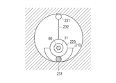
- FIG. 14 is a cross-sectional view taken along line 14-14 of FIG.
- FIG. 15 is a sectional view taken along line 15-15 in FIG.
- FIG. 17 is a cross-sectional view taken along line 17-17 in FIG. It is front sectional drawing of the front end side vicinity of a sheath main-body part when both the hand operation parts of the catheter which concerns on 2nd Embodiment are extracted.
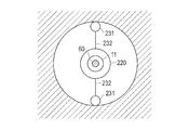
- FIG. 19 is a cross-sectional view taken along line 19-19 of FIG. It is a schematic block diagram of the catheter which concerns on the modification of this invention. It is a schematic block diagram of the catheter which concerns on the further another modification of this invention. It is a schematic block diagram of the catheter which concerns on the further another modification of this invention.
- proximal end side the hand operating part side of the device
- distal end side the side inserted into the living body lumen
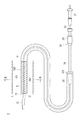
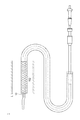
- FIG. 1 is a schematic configuration diagram of a catheter 1 according to a first embodiment of the present invention.
- FIG. 2 is a longitudinal sectional view showing a joint portion between the sheath body and the sheath tip member.
- an optical coherence tomography (OCT) catheter (hereinafter sometimes referred to as a catheter) 1 according to an embodiment of the present invention includes a sheath 10 inserted into a living body lumen L, and a sheath 10 Provided between the sheath 10 and an imaging core 21 (corresponding to an imaging member) for acquiring an image in the living body lumen L and the sheath 10 and a force along the radial direction of the sheath 10. And a moving member 100 that moves the sheath 10 in the radial direction. Details will be described below.
- the catheter 1 is a long and bendable sheath 10 that is inserted into the living body lumen L, an image acquisition means 20 for acquiring an optical coherence tomographic image in the living body lumen L, and the living body lumen L.
- the operation unit 30 is connected to the proximal end side of the sheath 10 and is not inserted into the sheath 10 and is operated by the user, and the moving member 100 that moves the sheath 10 in the radial direction.
- the sheath 10 includes a sheath body 11 and a sheath tip member 12 and is configured by joining the sheath body 11 and the sheath tip member 12.
- the sheath body 11 has a working lumen 11L in which the image acquisition means 20 is incorporated so as to be movable in the axial direction of the sheath 10.
- the sheath tip member 12 has a guide wire lumen 12L through which the guide wire W is inserted.
- the guide wire W is inserted into the living body lumen L in advance, and the catheter 1 is guided to the affected area while passing the guide wire W through the sheath distal end member 12.
- an X-ray contrast marker 14 is provided in the vicinity of the distal end of the sheath distal end member 12 so that the distal end position of the catheter 1 can be confirmed under fluoroscopy when inserted into the living body lumen L.
- the tube wall of the sheath 10 is formed such that the proximal end side of the sheath distal end member 12 transmits an optical signal.
- the catheter 1 according to this embodiment is a catheter 1 that acquires an image using an optical signal using OCT, and an optical coherence tomographic image can be obtained by transmitting and receiving light through the tube wall of the sheath 10.
- the image acquisition means 20 includes an imaging core 21 that houses a side-illuminated lens 212 for transmitting and receiving light toward the tissue in the living body lumen L in the housing 211, the imaging core 21 attached to the tip, and rotational power.
- a drive shaft 22 that transmits light
- an elastic member 23 that is connected to the distal end side of the imaging core 21 to prevent the sheath 10 from being caught when moving the imaging core 21 back and forth, and is inserted into the drive shaft 22 to transmit light.
- an optical fiber 24 for guiding light.
- the housing 211 is fixed to the distal end side of the drive shaft 22, and the side irradiation type lens 212 is fixed to the distal end side of the optical fiber 24.
- the fixing method is not particularly limited, and for example, it can be bonded with an adhesive.
- the drive shaft 22 is flexible and has a characteristic capable of transmitting the mechanical driving force from the driving unit D transmitted through the optical connector 51 described later to the imaging core 21.
- the imaging core 21 translates while rotating, and the affected part in the living body lumen L can be observed 360 degrees.
- the elastic member 23 is preferably made of a metal material.
- the elastic member 23 is made of a spring steel, stainless steel, a superelastic alloy, a cobalt-based alloy, a metal such as gold, platinum, tungsten, or an alloy containing these.
- the elastic member 23 can also be manufactured with other than a metal material.
- the operation unit 30 is connected to the hub 31 on the proximal end side, the unit connector 33 connected to the hub 31 via the inner pipe 32, and the unit connector 33 via the outer pipe 34. And a relay connector 35 for connecting the sheath 10 and the operation unit 30.
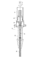
- FIG. 3 is a longitudinal sectional view of the hub 31. As shown in FIG. 3, the hub 31 includes a first outer housing 40 and a second outer housing 50.
- the first outer housing 40 has a collar member 41 that defines the rotation axis of the drive shaft 22, and the drive shaft 22 and the optical fiber 24 are provided inside the second outer housing 50 through the collar member 41. Connected to the optical connector 51.
- the second outer housing 50 holds a part of the first outer housing 40 and rotatably holds the optical connector 51 that transmits the mechanical driving force from the driving unit D to the drive shaft 22.
- FIG. 4 (moving member 100 is omitted for clarity) is a schematic diagram showing the catheter 1 when the imaging core 21 is pushed most into the sheath body 11.
- FIG. 5 (moving member 100 is omitted for clarity) is a schematic view showing the catheter 1 when the imaging core 21 is most pulled out from the sheath body 11.
- the inner tube 32 is pushed into the unit connector 33 and the outer tube 34 and pulled out as shown in FIG. 5, whereby the drive shaft 22 is interlocked to move the inside of the sheath body 11 in the axial direction.
- the imaging core 21 is most pulled out from the sheath body 11, that is, when the inner tube 32 is most pulled out, as shown in FIG.
- the inner tube 32 has a stopper 32A formed at the tip thereof as a unit connector. It is caught by the inner wall of 33 and parts other than the vicinity of the caught tip are exposed. In this state, the imaging core 21 is pulled back inside the sheath main body 11, and thus is positioned at a position facing the drive unit D by the amount the inner tube 32 is pulled out. By moving the imaging core 21 while rotating, an optical coherence tomographic image in the living body lumen L can be continuously acquired, and a three-dimensional image can be acquired.
- FIG. 6 is a longitudinal sectional view of the unit connector 33 and the relay connector 35.
- the unit connector 33 includes a unit connector main body 331, a sealing member 332, and a packing 333.
- An outer tube 34 attached to the relay connector 35 is inserted into the unit connector body 331, and an inner tube 32 extending from the hub 31 is inserted into the outer tube 34.
- the sealing member 332 holds the packing 333 in combination with the unit connector main body 331.
- the inner pipe 32 extending from the hub 31 is formed with a stopper 32A at the tip, even when the hub 31 is most pulled, that is, when the inner pipe 32 is most pulled out from the outer pipe 34, the stopper 32A is The inner pipe 32 is not pulled out from the unit connector 33 by being caught on the inner wall of the connector main body 331.
- the relay connector 35 holds the outer tube 34.
- the proximal end of the sheath body 11 is connected to the inner surface of the relay connector 35, and a path for introducing the drive shaft 22 passing through the outer tube 34 into the sheath body 11 is formed.
- the protective tube 7 is fixed to the inner wall of the outlet member 36 through which the drive shaft 22 of the relay connector 35 passes.
- the protective tube 7 extends toward the inner tube 32 extending from the hub 31. Therefore, when the inner tube 32 is pushed into the outer tube 34, the protective tube 7 is pushed into the inner tube 32 in the direction opposite to the pushing direction. When the inner tube 32 is pushed into or pulled out from the outer tube 34, the protective tube 7 is also pushed into or pulled out from the inner tube 32 in the opposite direction. Therefore, even if the drive shaft 22 comes into contact with the inner tube 32 and friction occurs, and the force that bends to the drive shaft 22 is generated, the force that is deflected by the protective tube 7 can be suppressed, and bending or the like can be prevented.
- the moving member 100 is disposed on the outer periphery of the sheath main body 11 and is movable in the axial direction of the sheath main body 11, and between the sheath main body 11 and the sheath member 101.
- a resilient member 102 that is housed in the space S and is capable of biasing a resilient force that moves the sheath 10 in the radial direction, and a hand operating unit 103 that moves the sheath member 101 in the axial direction.
- the sheath member 101 is a sheath piece that is divided into two so that one hollow member is equally divided in the axial direction of the sheath body 11, and can be moved in the axial direction by the hand operation unit 103.
- the elastic member 102 is a self-expandable mesh structure that expands in the radial direction.
- a material such as a resin such as metal or polyethylene is used.
- Two elastic members 102 are provided in the axial direction.
- FIG. 7 is a schematic view showing the catheter 1 when one side of the hand operation unit 103 is pulled out.
- the right end of the elastic member 102 is fixed to the outer periphery of the sheath body 11, and the sheath member 101 is pulled out so as to expose the sheath body 11.
- the resilient member 102 accommodated in the space S expands in the radial direction, and the repulsive force along the radial direction of the sheath main body 11 generated by the resilient member 102 pushing the living body lumen L is applied to the sheath 10. It gives to.
- the expanded elastic member 102 has a space S between the sheath main body portion 11 and the sheath member 101. It is stored in.
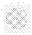
- FIGS. 8 is a cross-sectional view taken along line 8-8 in FIG. 1
- FIG. 9 is a cross-sectional view taken along line 9-9 in FIG.
- FIG. 10 is a schematic view showing the catheter 1 when both of the hand operating portions 103 of the catheter according to the first embodiment are pulled out.
- FIG. 11 is a sectional view taken along line 11-11 in FIG.
- the elastic member stored in the space S between the sheath main body portion 11 and the sheath member 101 is moved by moving one of the proximal operation portions 103 to the proximal end side.
- the emitting member 102 expands in the radial direction.
- the resilient member 102 is expanded upward in FIGS. Since the elastic member 102 applies an upward force to the living body lumen L, a downward force is applied to the sheath body 11 as the repulsive force, and the sheath 10 is displaced downward.
- the sheath 10 is displaced to the lesion site side by appropriately rotating the sheath 10 around the axis.
- the other hand operating unit 103 that has not been moved is moved to the proximal end side.
- the elastic member 102 that has been expanded only to the upper side expands to the lower side, and a downward force is applied to the living body lumen L.
- a repulsive force an upward force is applied to the sheath body 11. Power is granted. Therefore, since the elastic member 102 is expanded over the entire circumference, the sheath 10 can be arranged at the center in the living body lumen L.
- the optical coherence tomographic image of the entire body lumen L can be continuously acquired and a three-dimensional image can be acquired.
- the expanded elastic member 102 is accommodated in the space S by pushing the sheath member 101 so that the sheath body 11 is covered.
- a force along the radial direction of the sheath body 11 is applied to the sheath 10 by the moving member 100, and the sheath 10 can be moved in the radial direction. For this reason, the sheath 10 can be appropriately moved in the radial direction in the living body lumen L.
- the moving member 100 is disposed at a position where the radial position of the sheath 10 is deviated from the center in the living body lumen L or in the center in the living body lumen L. For this reason, for example, when it is desired to gaze at the lesion before surgery, the sheath 10 can be displaced toward the lesion, and the lesion can be gazeed. Further, when it is desired to observe the entire inside of the living body lumen L after the operation, the sheath 10 can be arranged at the center in the living body lumen L, and the entire inside of the living body lumen L can be observed.
- the moving member 100 is disposed on the outer periphery of the sheath body 11 and is housed in a sheath member 101 that is movable in the axial direction, and a space S between the sheath body 11 and the sheath member 101, and the sheath 10 has a diameter.
- a resilient member 102 that is capable of biasing a resilient force that moves in a direction, and the sheath member 101 is pulled out so as to expose the sheath body 11, so that the accommodated resilient member 102 has a diameter.
- the sheath 10 can be moved in the radial direction in the living body lumen L by pulling out or pushing in the sheath member 101. Therefore, it becomes possible to arrange the sheath 10 at a position displaced from the center in the body lumen L or at the center depending on the situation.
- the sheath member 101 is a sheath piece that is divided into two so that one hollow member is equally divided in the axial direction of the sheath body 11. For this reason, by pulling out one of the sheath members 101, the sheath 10 can be arranged at a position displaced from the center in the living body lumen L, and by pulling out both of the sheath members 101, the sheath 10 can be placed in the living body lumen L. Can be placed in the center of the inside. Therefore, according to the situation, the sheath 10 can be disposed at a position displaced from the center in the living body lumen L or at the center.
- the elastic members 102 are two self-expandable mesh structures that are arranged in the axial direction and expand in the radial direction, and one end of the mesh structure is fixed to the outer periphery of the sheath body 11. .
- the sheath 10 can be arranged at a position displaced from the center in the body lumen L or at the center by pulling out or pushing in the sheath member 101 according to the situation.
- FIG. 12 is a schematic configuration diagram of the catheter 2 according to the second embodiment.
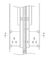
- FIG. 13 is a front sectional view of the vicinity of the distal end side of the sheath main body 11 according to the second embodiment.
- FIG. 14 is a cross-sectional view taken along line 14-14 of FIG.
- FIG. 15 is a sectional view taken along line 15-15 in FIG.
- the catheter 2 according to the second embodiment of the present invention is inserted into the sheath body 11, and includes a drive shaft 60 including the imaging core 21 and the first magnetic member 61 therein, A moving member 200 that is disposed between the sheath main body 11 and the living body lumen L and moves the sheath 10 in the radial direction by applying a force along the radial direction of the sheath main body 11 to the sheath 10; Have.
- Other configurations are the same as those in the first embodiment.
- the drive shaft 60 includes an imaging core 21 and three first magnetic members 61 in the axial direction.
- the three first magnetic members 61 all have N-pole magnetism and have a uniform magnetic force in the radial direction.
- the magnetic member generally has both S-pole and N-pole magnetism, and the expression of having the N-pole magnetism described here has the S-pole inside and the N-pole on the outer periphery. The same shall apply hereinafter.
- the moving member 200 is disposed on the outer periphery of the sheath body 11 and is disposed in an elongated shape between the sheath member 210 that is movable in the axial direction, and between the sheath body 11 and the sheath member 210, and the third magnetic member 221. And a resilient member 230 that is housed in a space S1 between the tube 220 and the sheath member 210 and that can freely bias the resilient force that moves the sheath 10 in the radial direction.
- the sheath member 210 is a sheath piece that is divided into two so that one hollow member is equally divided in the axial direction of the sheath main body 11, and can be moved in the axial direction by the hand operating portion 201.
- the tube 220 is made of a material such as metal or polyethylene.
- the third magnetic member 221 has S pole magnetism and is arranged in the circumferential direction of the tube 220 as shown in FIGS. Since the third magnetic member 221 has S-pole magnetism, the first magnetic member 61 disposed in the vicinity of the third magnetic member 221 acts as an attractive force, and the tube moves along with the axial movement of the drive shaft 60. 220 can be moved axially.
- the elastic member 230 includes a second magnetic member 231 having N-pole magnetism, and a wire 232 connecting the outer periphery of the tube 220 and the second magnetic member 231. Further, as shown in FIGS. 13 and 14, two elastic members 230 are provided at opposite positions in the circumferential direction of the sheath 10 so as to correspond to the divided positions of the sheath member 210, and are provided at two locations in the axial direction. A total of four are provided. Since the second magnetic member 231 has N-pole magnetism, repulsive force works with the first magnetic member 61 disposed in the vicinity of the second magnetic member 231. Further, all the second magnetic members 231 have the same magnetic force.
- FIG. 16 is a front cross-sectional view of the vicinity of the distal end side of the sheath body 11 when one side of the hand operation unit 201 is pulled out.
- the elastic member 230 accommodated in the space S ⁇ b> 1 is pulled between the first magnetic member 61 and the second magnetic member 231 by pulling the sheath member 210 so as to expose the tube 220.
- the repulsive force is expanded in the radial direction by the repulsive force, and the repulsive force along the radial direction of the sheath main body 11 generated by the elastic member 230 pushing the living body lumen L is applied to the sheath 10.
- FIG. 13 when the sheath member 210 is pushed so as to cover the tube 220, the expanded elastic member 230 is accommodated in the space S ⁇ b> 1.
- the material of the wire 232 is preferably a resin, such as polyethylene, but is not limited thereto. Moreover, all the lengths of the wire 232 are the same.
- FIG. 17 is a sectional view taken along the line 17-17 in FIG.
- FIG. 18 is a front cross-sectional view of the vicinity of the distal end side of the sheath main body 11 when both the hand operating portions 201 according to the second embodiment are pulled out.
- FIG. 19 is a sectional view taken along line 19-19 in FIG.
- the sheath 10 is not applied with a force in the radial direction. I can't move. In this case, for example, when it is desired to gaze at the lesion in the living body lumen L before the operation, it is necessary to move the sheath 10 to the lesion along the radial direction.
- the elastic member 230 housed in the space S ⁇ b> 1 is moved from the first magnetic member 61 to the first magnetic member 61 by moving one hand operating unit 201 to the proximal end side. It expands in the radial direction by the repulsive force with the two magnetic members 231.
- the resilient member 230 is expanded upward in FIGS. Since the resilient member 230 applies an upward force to the living body lumen L, a downward force is applied to the sheath body 11 as the repulsive force, and the sheath 10 is displaced downward.
- the sheath 10 is displaced to the lesion site side by appropriately rotating the sheath 10 around the axis.
- the other hand operating unit 201 that has not been moved is moved to the proximal end side.
- the elastic member 230 expands downward, and a downward force is applied to the living body lumen L. Therefore, an upward force is applied to the sheath body 11 as the repulsive force. Therefore, the downward force generated by moving the upper side of the hand operation unit 201 and the upward force generated by moving the lower side of the hand operation unit 201 are balanced, and the sheath 10 is centered in the living body lumen L. Can be arranged.
- the tube 220 is also pulled out at the same time, and optical coherence tomographic images of the entire body lumen L are continuously acquired, and a three-dimensional image is obtained. Can be acquired.
- the expanded elastic member 230 is accommodated in the space S1 by pushing the sheath member 210 so as to cover the sheath main body 11.
- a force along the radial direction of the sheath body 11 is applied to the sheath 10 by the moving member 200, and the sheath 10 can be moved in the radial direction. For this reason, the sheath 10 can be moved in the radial direction in the living body lumen L.
- first magnetic members 61 are provided in the axial direction of the sheath body 11, and the moving member 200 is disposed in a long shape between the sheath body 11 and the sheath member 210, and the third magnetic member 61
- the elastic member 230 is further accommodated in a space between the tube 220 and the sheath member 210, and the other end of the wire 232 is connected to the outer periphery of the tube 220.
- the tube 220 is moved in the axial direction with the movement of the drive shaft 60 in the axial direction by the attractive force with 221. For this reason, the second magnetic member 231 is not disposed on the outer periphery of the imaging core 21, and the imaging of the imaging core 21 is not hindered by the second magnetic member 231.
- the sheath members 101 and 210 are sheath pieces that are divided into two so that one hollow member is equally divided in the axial direction of the sheath body 11. As shown in FIG. 20, it may be a single hollow member. At this time, it becomes easy to arrange the radial position of the sheath 10 in the center of the living body lumen L.
- the sheath member 101 is divided into two parts so as to be equally divided in the axial direction, and the elastic member 102 is expanded, whereby the sheath 10 is expanded.
- the sheath 10 may be divided into three or more so that the sheath member 101 is equally divided in the axial direction.
- the sheath 10 can be disposed in the center of the living body lumen L with higher accuracy.
- the sheath member 210 is divided into two parts so as to be equally divided in the axial direction, and the elastic member 230 is expanded, whereby the sheath 10.
- the sheath member 210 is divided into three or more (four in FIG. 21) so as to be equally divided in the axial direction, and the elastic member 230 is Three or more (four in FIG. 21) may be provided in the direction.
- the sheath 10 can be disposed in the center of the living body lumen L with higher accuracy.
- the other end of the wire 232 is connected to the tube 220 as shown in FIG.
- the other end of the wire 232 may be provided on the outer periphery of the sheath body 11. At this time, the tube 220 becomes unnecessary, and the number of components can be reduced.
- the four second magnetic members 231 have the same magnetic force, but may have different magnetic forces. At this time, a difference is generated in the repulsive force generated between the first magnetic member 61 and the sheath 10 can be displaced.
- the lengths of the wires 232 are all the same, but the lengths may be different from each other. At this time, the sheath 10 can be displaced by the difference in the length of the wire.
- two elastic members 102 and 230 are provided in the axial direction, but may be one or three or more.
- the optical coherence tomography catheter is used.
- the optical coherence tomography catheter may be used.
- Imaging core imaging member
- 60 drive shaft 61 1st magnetic member, 100, 200 moving member, 101, 210 sheath member, 102,230 bullet member, 220 tubes, 221 third magnetic member; 231 second magnetic member, 232 wire rod, L biological lumen, S, S1, S2 space.
Landscapes
- Health & Medical Sciences (AREA)
- Life Sciences & Earth Sciences (AREA)
- Biomedical Technology (AREA)
- Molecular Biology (AREA)
- Veterinary Medicine (AREA)
- Biophysics (AREA)
- Pathology (AREA)
- Engineering & Computer Science (AREA)
- Public Health (AREA)
- Heart & Thoracic Surgery (AREA)
- Medical Informatics (AREA)
- Physics & Mathematics (AREA)
- Surgery (AREA)
- Animal Behavior & Ethology (AREA)
- General Health & Medical Sciences (AREA)
- Nuclear Medicine, Radiotherapy & Molecular Imaging (AREA)
- Radiology & Medical Imaging (AREA)
- Endoscopes (AREA)
- Media Introduction/Drainage Providing Device (AREA)
Description
本発明は、医療用デバイスに関する。
近年医療分野にて、カテーテルと呼ばれる細長く柔らかい中空管状の医療器具を用いて、様々な治療や検査が行われている。治療方法の例としては、カテーテルの長尺性を利用して直接患部に薬剤を投与する方法、加圧によって拡張されるバルーンが先端に取り付けられたカテーテルを用いて、体腔内の狭窄部を押し広げて開く方法、先端部にカッターが取り付けられたカテーテルを用いて患部を削り取る方法、逆にカテーテルを用いて動脈瘤や出血箇所あるいは栄養血管に詰め物をして閉じる方法などがある。また、体腔内の狭窄部を開口した状態に維持するために、側面が網目状になっている管形状をしたステントをカテーテルを用いて体腔内に埋め込んで留置する治療方法などがある。さらに、体内にとって過剰となった液体をカテーテルを介して吸引することなどがある。
診断用のカテーテルは、主にこのような体腔内の狭窄部の経皮的な治療の際に、狭窄部の性状を観察し、治療手段を選択するための判断の一助として用いられ、また、治療後の状態の観察にも用いられている。
診断用のカテーテルとしては、たとえば、低干渉光を利用した光干渉断層撮影(OCT:Optical Coherence Tomography)カテーテル(例えば特許文献1参照)や、超音波検出器によりセンシングを行う超音波カテーテル等がある。
これらの診断用のカテーテルでは、内部に設けられた撮像部材によって、カテーテルに設けられたシースの軸直交断面において、シースを中心に同心円状の領域を観察することができる。
引用文献1のカテーテルを用いて生体管腔内を観察する場合、生体管腔内においてシースを径方向に適宜移動させることができず、シースを病変部に偏位させて病変部を注視することや、シースを生体管腔内の中央に配置させて生体管腔内全体を観察することが困難である。
本発明は、上記課題を解決するためになされたものであり、生体管腔内においてシースを径方向に適宜移動することのできる医療用デバイスを提供することを目的とする。
上記目的を達成する本発明に係る医療用デバイスは、生体管腔内に挿入されるシースと、前記シース内に設けられ、前記生体管腔内の画像を取得する撮像部材と、前記シースと前記生体管腔との間に配置され前記シースの径方向に沿う力を前記シースに対して付与することによって前記シースを径方向に移動させる移動部材と、を有する医療用デバイスである。
上記のように構成された医療用デバイスであれば、移動部材によって、シースの径方向に沿う力がシースに対して付与され、シースを径方向に移動させることができる。このため、生体管腔内においてシースを径方向に適宜移動させることができる。
<第1実施形態>
以下、図面を参照して、本発明の実施の形態を説明する。なお、図面の寸法比率は、説明の都合上、誇張されて実際の比率とは異なる場合がある。また、以下の説明において、デバイスの手元操作部側を「基端側」、生体管腔内へ挿通される側を「先端側」と称する。
以下、図面を参照して、本発明の実施の形態を説明する。なお、図面の寸法比率は、説明の都合上、誇張されて実際の比率とは異なる場合がある。また、以下の説明において、デバイスの手元操作部側を「基端側」、生体管腔内へ挿通される側を「先端側」と称する。
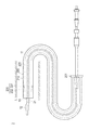
図1は本発明の第1実施形態に係るカテーテル1の概略構成図である。図2はシース本体部とシース先端部材との接合部分を示す長手方向断面図である。
図1に示すように本発明の実施形態に係る光干渉断層撮影(OCT)カテーテル(以下、カテーテルと称する場合がある)1は、生体管腔L内に挿入されるシース10と、シース10内に設けられ、生体管腔L内の画像を取得するイメージングコア21(撮像部材に相当する)と、シース10と生体管腔Lとの間に配置されシース10の径方向に沿う力をシース10に対して付与することによってシース10を径方向に移動させる移動部材100と、を有する。以下、詳述する。
カテーテル1は、長尺状かつ湾曲自在であり生体管腔L内に挿入されるシース10と、生体管腔L内の光干渉断層画像を取得するための画像取得手段20と、生体管腔L内に挿入されずシース10の基端側に接続され使用者が操作するための操作部30と、シース10を径方向に移動させる移動部材100と、を有する。
図2に示すように、シース10は、シース本体部11と、シース先端部材12と、を有し、シース本体部11及びシース先端部材12を接合することによって構成される。
シース本体部11は、内部に画像取得手段20がシース10の軸方向に移動可能に内蔵されているワーキングルーメン11Lを有する。
シース先端部材12は、内部にガイドワイヤWが挿通されるためのガイドワイヤルーメン12Lを有する。ガイドワイヤWは予め生体管腔L内に挿入され、ガイドワイヤWをシース先端部材12に通しながら、カテーテル1が患部まで導かれる。
また、シース先端部材12の先端近傍にはX線造影マーカ14が設けられており、生体管腔L内挿入時にX線透視下においてカテーテル1の先端位置が確認できるようになっている。
シース10の管壁は、シース先端部材12よりも基端側が、光信号を透過するように形成されている。本実施形態に係るカテーテル1は、OCTを利用した光信号により画像を取得するカテーテル1であり、シース10の管壁を介して光を送受信することで、光干渉断層画像を得ることができる。
画像取得手段20は、生体管腔L内組織に向けて光を送受信するための側方照射型のレンズ212をハウジング211内に収容するイメージングコア21と、イメージングコア21を先端に取り付けるとともに回転動力を伝達するドライブシャフト22と、イメージングコア21の先端側に連結されイメージングコア21を前後移動させる際にシース10内での引っ掛かりを防止する弾性部材23と、ドライブシャフト22の内部に挿通され光を導光する光ファイバ24と、を有する。
ハウジング211は、ドライブシャフト22の先端側に固定され、側方照射型のレンズ212は、光ファイバ24の先端側に固定されている。固定方法は特に限定されず、たとえば、接着剤によって接着することができる。
ドライブシャフト22は柔軟で、後述する光コネクタ51を介して伝達される駆動部Dからの機械的駆動力をイメージングコア21に伝達可能な特性をもっている。ドライブシャフト22が機械的駆動力を伝達することによって、イメージングコア21が回転しつつ並進し、生体管腔L内の患部を360度観察することができる。
弾性部材23は、金属材料で作製されることが好ましく、たとえば、バネ鋼、ステンレス鋼、超弾性合金、コバルト系合金や、金、白金、タングステン等の金属またはこれらを含む合金等によって作製される。なお、弾性部材23を、金属材料以外によって製造することもできる。
操作部30は、図1に示すように、基端側のハブ31と、内管32を介してハブ31と接続されるユニットコネクタ33と、外管34を介してユニットコネクタ33に接続されるとともにシース10及び操作部30を接続する中継コネクタ35と、を有する。
図3は、ハブ31の長手方向断面図である。図3に示すように、ハブ31は、第1の外側ハウジング40と、第2の外側ハウジング50と、を有する。
第1の外側ハウジング40は、ドライブシャフト22の回転軸を規定するカラー部材41を有し、ドライブシャフト22及び光ファイバ24はカラー部材41を通って、第2の外側ハウジング50の内部に設けられた光コネクタ51に接続される。
第2の外側ハウジング50は、第1の外側ハウジング40の一部を保持し、駆動部Dからの機械的駆動力をドライブシャフト22に伝達する光コネクタ51を回転可能に保持する。
図4(明瞭化のため移動部材100は省略)はイメージングコア21をシース本体部11に最も押し込んだときのカテーテル1を示す概略図である。図5(明瞭化のため移動部材100は省略)はイメージングコア21をシース本体部11から最も引き抜いたときのカテーテル1を示す概略図である。図4に示すように、内管32がユニットコネクタ33及び外管34に押し込まれ、図5に示すように、引き出されることによって、ドライブシャフト22が連動してシース本体部11内を軸方向にスライドする
また、イメージングコア21をシース本体部11から最も引き抜いたとき、すなわち内管32を最も引き出したときには、図5に示すように、内管32は、先端に形成されたストッパ32Aがユニットコネクタ33の内壁に引っかかり、引っかかった先端付近以外が露出する。そして、この状態では、イメージングコア21は、シース本体部11の内部を引き戻されていくので、内管32を引き出した分だけ駆動部Dの方に向かった場所に位置する。イメージングコア21が回転しながら移動することによって、生体管腔L内の光干渉断層画像を連続的に取得し、3次元画像を取得することができる。
また、イメージングコア21をシース本体部11から最も引き抜いたとき、すなわち内管32を最も引き出したときには、図5に示すように、内管32は、先端に形成されたストッパ32Aがユニットコネクタ33の内壁に引っかかり、引っかかった先端付近以外が露出する。そして、この状態では、イメージングコア21は、シース本体部11の内部を引き戻されていくので、内管32を引き出した分だけ駆動部Dの方に向かった場所に位置する。イメージングコア21が回転しながら移動することによって、生体管腔L内の光干渉断層画像を連続的に取得し、3次元画像を取得することができる。
図6は、ユニットコネクタ33及び中継コネクタ35の長手方向断面図である。ユニットコネクタ33は、ユニットコネクタ本体331と、封止部材332と、パッキン333と、を有する。
ユニットコネクタ本体331には、中継コネクタ35に取り付けられた外管34が挿入され、この外管34の内部にはハブ31から伸びた内管32が挿入される。封止部材332は、ユニットコネクタ本体331と組み合わさってパッキン333を保持する。
また、ハブ31から伸びる内管32は、先端にストッパ32Aが形成されているので、ハブ31を最も引っ張ったとき、すなわち、内管32を外管34から最も引き出したときでも、ストッパ32Aがユニットコネクタ本体331の内壁に引っ掛かってユニットコネクタ33から内管32が抜けることはない。
中継コネクタ35は、外管34を保持する。また、中継コネクタ35の内面には、シース本体部11の基端側端部が連結されており、外管34から通り抜けたドライブシャフト22をシース本体部11に導入する経路が形成されている。
中継コネクタ35のドライブシャフト22が通り抜ける出口部材36の内壁には、保護管7が固定されている。この保護管7は、ハブ31から伸びる内管32内に向かって伸びる。従って、外管34に内管32が押し込まれるときには、その押し込みの向きと反対向きに内管32に保護管7が押し込まれていくことになる。外管34に内管32が押し込まれたり引き出されたりする際に、反対方向から保護管7も内管32に相対的に押し込まれたり引き出されたりする。従って、ドライブシャフト22が内管32に接触して摩擦が起こり、ドライブシャフト22に撓む力が発生しても、保護管7によって撓む力を抑制し、折れ曲がりなどを防止することができる。
移動部材100は、図1に示すように、シース本体部11の外周に配置され、シース本体部11の軸方向に移動可能な鞘部材101と、シース本体部11と鞘部材101との間の空間Sに収納され、シース10を径方向に移動させる弾発力を付勢自在な弾発部材102と、鞘部材101を軸方向に移動させる手元操作部103と、を有する。
鞘部材101は、1本の中空部材をシース本体部11の軸方向に等分されるように2分割された鞘片であり、手元操作部103によって、軸方向に移動可能である。
弾発部材102は、径方向に拡張する自己拡張可能なメッシュ構造物であって、例えば金属やポリエチレンなどの樹脂のような材質が用いられる。また、弾発部材102は軸方向に2つ設けられている。
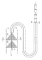
図7は、手元操作部103の一方を引き抜いたときのカテーテル1を示す概略図である。図7に示すように、弾発部材102の右端は、シース本体部11の外周に固定されており、鞘部材101がシース本体部11を露出させるように引き抜かれる。すると、空間Sに収納されている弾発部材102が径方向に拡張して、弾発部材102が生体管腔Lを押すことによって生じるシース本体部11の径方向に沿う反発力をシース10に対して付与する。また、図1に示すように、鞘部材101がシース本体部11を覆い隠すように押し込まれることによって、拡張されている弾発部材102がシース本体部11と鞘部材101との間の空間Sに収納される。
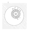
次に、本実施形態に係るカテーテル1の作用について図1,7~11を参照して説明する。図8は図1の8-8線に沿う断面図であり、図9は図7の9-9線に沿う断面図である。図10は第1実施形態に係るカテーテルの手元操作部103の双方を引き抜いたときのカテーテル1を示す概略図である。図11は図10の11-11線に沿う断面図である。
まず、図1,8に示すように、弾発部材102が空間Sに収納されているとき、シース10には径方向に力が付与されないため、生体管腔L内においてシース10を径方向に適宜移動させることができない。この場合において、例えば手術前に生体管腔L内の病変部を注視したいとき、シース10を当該病変部側へ径方向に沿って移動させる必要がある。
このため、次に図7,9に示すように、一方の手元操作部103を基端側に移動させることによって、シース本体部11と鞘部材101との間の空間Sに収納されていた弾発部材102が径方向に拡張する。ここで、分割された鞘部材101の鞘片の1つが移動するため、弾発部材102は、図7,9において上向きに拡張される。弾発部材102は、生体管腔Lに対して上向きの力を付与するため、この反発力として、シース本体部11には下向きの力が付与され、シース10は下方向に偏位される。
次に、シース10を軸周りに適宜回転することによって、シース10を病変部側に偏位させる。
そして、適切な手術を行った後に、次に生体管腔L内の周方向全体を観察するために、シース10を生体管腔L内の中央に配置させる必要がある。
よって次に、図10,11に示すように、移動されていない他方の手元操作部103を基端側に移動させる。この結果、上側のみに拡張されていた弾発部材102が下側にも拡張し、生体管腔Lに対して下向きの力が付与されるため、この反発力として、シース本体部11に上向きの力が付与される。よって、弾発部材102が全周に渡って拡張されるため、シース10を生体管腔L内の中央に配置させることができる。
この状態で、駆動部Dを用いてイメージングコア21を回転させつつ引き戻すことによって、生体管腔L内全体の光干渉断層画像を連続的に取得し、3次元画像を取得することができる。
そして、光干渉断層画像を取得した後に、鞘部材101をシース本体部11が覆い隠されるように押し込むことによって、拡張されている弾発部材102を空間Sに収納する。
以上のように第1実施形態によれば、移動部材100によって、シース本体部11の径方向に沿う力がシース10に対して付与され、シース10を径方向に移動させることができる。このため、生体管腔L内においてシース10を径方向に適宜移動させることができる。
また、移動部材100は、シース10の径方向の位置を生体管腔L内の中央から偏位した位置、または生体管腔L内の中央に配置させる。このため、例えば手術前において病変部を注視したいときに、病変部側にシース10を偏位させることができ、病変部を注視することができる。また手術後において生体管腔L内全体を観察したいとき、シース10を生体管腔L内の中央に配置させることができ、生体管腔L内全体を観察することができる。
また、移動部材100は、シース本体部11の外周に配置され、軸方向に移動可能な鞘部材101と、シース本体部11と鞘部材101との間の空間Sに収納され、シース10を径方向に移動させる弾発力を付勢自在な弾発部材102と、を有し、鞘部材101がシース本体部11を露出させるように引き抜かれることによって、収納されている弾発部材102が径方向に拡張してシ-ス本体部11の径方向に沿う力をシース10に対して付与し、鞘部材101がシース本体部11を覆い隠すように押し込まれることによって、拡張されている弾発部材102が空間Sに収納される。このため、鞘部材101を引き抜いたり、押し込んだりすることによって、生体管腔L内においてシース10を径方向に移動させることができる。よって、状況に応じて、シース10を生体管腔L内の中央から偏位した位置または中央に配置することが可能となる。
また、鞘部材101は、1本の中空部材をシース本体部11の軸方向に等分されるように2分割された鞘片である。このため、鞘部材101の一方を引き抜くことによって、シース10を生体管腔L内の中央から偏位した位置に配置でき、また鞘部材101の双方を引き抜くことによって、シース10を生体管腔L内の中央に配置できる。よって、状況に応じて、シース10を生体管腔L内の中央から偏位した位置または中央に配置することができる。
また、弾発部材102は、軸方向に2つ配置され、径方向に拡張する自己拡張可能なメッシュ構造物であって、メッシュ構造物の片端は、シース本体部11の外周に固定されている。このため、状況に応じて鞘部材101を引き抜いたり押し込んだりすることによって、シース10を生体管腔L内の中央から偏位した位置または中央に配置することができる。
<第2実施形態>
次に、本発明の第2実施形態を説明する。第1実施形態と共通する部分は説明を省略し、第2実施形態のみに特徴のある箇所について説明する。
次に、本発明の第2実施形態を説明する。第1実施形態と共通する部分は説明を省略し、第2実施形態のみに特徴のある箇所について説明する。
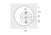
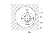
図12は第2実施形態に係るカテーテル2の概略構成図である。図13は第2実施形態に係るシース本体部11の先端側近傍の正面断面図である。図14は図13の14-14線に沿う断面図である。図15は図13の15-15線に沿う断面図である。
本発明の第2実施形態に係るカテーテル2は、図12~14に示すように、シース本体部11内に挿入され、内部にイメージングコア21及び第1の磁性部材61を備えるドライブシャフト60と、シース本体部11と生体管腔Lとの間に配置され、シース本体部11の径方向に沿う力をシース10に対して付与することによってシース10を径方向に移動させる移動部材200と、を有する。なお、その他の構成は第1実施形態と同様である。
ドライブシャフト60は、図13に示すように、内部にイメージングコア21及び軸方向に3つの第1の磁性部材61を有する。
3つの第1の磁性部材61は、すべてN極の磁性を有し、径方向に均一の磁力を有する。なお、磁性部材は一般的にS極、N極どちらの磁性も有しており、ここで記載しているN極の磁性を有するという表現は、内部にS極、外周にN極を有するものを意味し、以後同様とする。
移動部材200は、シース本体部11の外周に配置され、軸方向に移動可能な鞘部材210と、シース本体部11及び鞘部材210の間に長尺状に配置され、第3の磁性部材221を有するチューブ220と、チューブ220と鞘部材210との間の空間S1に収納され、シース10を径方向に移動させる弾発力を付勢自在な弾発部材230と、を有する。
鞘部材210は、1本の中空部材をシース本体部11の軸方向に等分されるように2分割された鞘片であり、手元操作部に201によって、軸方向に移動可能である。
チューブ220は、例えば金属やポリエチレンなどの材質からなる。
第3の磁性部材221は、S極の磁性を有し、図13,15に示すように、チューブ220の周方向に配置される。第3の磁性部材221は、S極の磁性を有するため、第3の磁性部材221近傍に配置される第1の磁性部材61と引力が働き、ドライブシャフト60の軸方向の移動に伴ってチューブ220を軸方向に移動させることができる。
弾発部材230は、N極の磁性を有する第2の磁性部材231と、チューブ220の外周及び第2の磁性部材231を連結させる線材232と、を有する。また、弾発部材230は図13,14に示すように、鞘部材210の分割位置に対応するように、シース10の周方向の対向する位置に2つ設けられ、かつ軸方向に2箇所設けられ、計4つ設けられている。第2の磁性部材231は、N極の磁性を有するため、第2の磁性部材231近傍に配置される第1の磁性部材61と斥力が働く。また、第2の磁性部材231はすべて同一の磁力を有する。
図16は、手元操作部201の一方を引き抜いたときのシース本体部11の先端側近傍の正面断面図である。図16に示すように、鞘部材210がチューブ220を露出させるように引き抜かれることによって、空間S1に収納されている弾発部材230が第1の磁性部材61と第2の磁性部材231との斥力によって径方向に拡張して、弾発部材230が生体管腔Lを押すことによって生じるシース本体部11の径方向に沿う反発力をシース10に対して付与する。また、図13に示すように、鞘部材210がチューブ220を覆い隠すように押し込まれることによって、拡張されている弾発部材230が空間S1に収納される。
線材232の材質は樹脂が好ましく、例えばポリエチレンなどが挙げられるが、この限りではない。また、線材232の長さはすべて同一である。
次に、第2実施形態に係るカテーテル2の作用について図13~19を参照して説明する。図17は図16の17-17線に沿う断面図である。図18は第2実施形態に係る手元操作部201の双方を引き抜いたときのシース本体部11の先端側近傍の正面断面図である。図19は図18の19-19線に沿う断面図である。
まず、図12~15に示すように、弾発部材230が空間S1に収納されているとき、シース10は径方向に力が付与されないため、生体管腔L内においてシース10を径方向に適宜移動することができない。この場合において、例えば手術前に生体管腔L内の病変部を注視したいとき、シース10を当該病変部へ径方向に沿って移動させる必要がある。
このため、次に図16,17に示すように、一方の手元操作部201を基端側に移動させることによって、空間S1に収納されていた弾発部材230が第1の磁性部材61と第2の磁性部材231との斥力によって径方向に拡張する。ここで、分割された鞘部材210の鞘片の1つが移動するため、弾発部材230は、図16,17において上向きに拡張される。弾発部材230が、生体管腔Lに対して上向きの力を付与するため、この反発力として、シース本体部11には下向きの力が付与され、シース10は下方向に偏位される。
次に、シース10を軸周りに適宜回転することによって、シース10を病変部側に偏位させる。
そして、適切な手術を行った後に、次に生体管腔L内の周方向全体を観察するために、シース10の径方向の位置を生体管腔L内の中央に配置させる必要がある。
よって次に、図18,19に示すように、まだ移動させていない他方の手元操作部201を基端側に移動させる。この結果、弾発部材230が下側にも拡張し、生体管腔Lに対して下向きの力が付与されるため、この反発力として、シース本体部11に上向きの力が付与される。よって、手元操作部201の上側を移動させることによって生じた下向きの力と、手元操作部201の下側を移動させることによって生じた上向きの力がつり合い、シース10を生体管腔L内の中央に配置することができる。
この状態で、駆動部Dを用いてイメージングコア21を回転させつつ引き出すことによって、チューブ220も同時に引き出され、生体管腔L内全体の光干渉断層画像を連続的に取得し、3次元画像を取得することができる。
そして、光干渉断層画像を取得した後に、鞘部材210をシース本体部11を覆い隠すように押し込むことによって、拡張されている弾発部材230を空間S1に収納する。
以上のように第2実施形態によれば、移動部材200によって、シース本体部11の径方向に沿う力がシース10に対して付与され、シース10を径方向に移動させることができる。このため、生体管腔L内においてシース10を径方向に移動させることができる。
また、第1の磁性部材61は、シース本体部11の軸方向に3つ設けられ、移動部材200は、シース本体部11及び鞘部材210の間に長尺状に配置され、第3の磁性部材221を有するチューブ220をさらに有し、弾発部材230は、チューブ220と鞘部材210との間の空間に収納され、線材232の他端は、チューブ220の外周に連結され、第1の磁性部材61の一方と第2の磁性部材231との斥力によって、シース本体部11の径方向に沿う力をシース10に対して付与し、第1の磁性部材61の他方と第3の磁性部材221との引力によって、ドライブシャフト60の軸方向の移動に伴ってチューブ220を軸方向に移動させる。このため、イメージングコア21の外周に第2の磁性部材231が配置されることがなく、第2の磁性部材231によってイメージングコア21の撮影が妨害されない。
(改変例)
本発明に係る第1~2実施形態では、鞘部材101,210は1本の中空部材をシース本体部11の軸方向に等分されるように2分割された鞘片であったが、図20に示すように、1本の中空部材であってもよい。このとき、シース10の径方向の位置を生体管腔L内の中央に配置することが容易となる。
本発明に係る第1~2実施形態では、鞘部材101,210は1本の中空部材をシース本体部11の軸方向に等分されるように2分割された鞘片であったが、図20に示すように、1本の中空部材であってもよい。このとき、シース10の径方向の位置を生体管腔L内の中央に配置することが容易となる。
また、本発明に係る第1実施形態では、図9,11に示すように、鞘部材101が軸方向に等分されるように2分割され、弾発部材102が拡張することによって、シース10を径方向に移動させたが、鞘部材101が軸方向に等分されるように3つ以上分割されてもよい。このとき、シース10をより精度よく生体管腔L内の中央に配置することができる。
また、本発明に係る第2実施形態では、図17,19に示すように、鞘部材210が軸方向に等分されるように2分割され、弾発部材230が拡張することによって、シース10を径方向に移動させたが、図21に示すように、鞘部材210が軸方向に等分されるように3つ以上(図21において4つ)分割され、かつ、弾発部材230が周方向に3つ以上(図21において4つ)設けられてもよい。このとき、シース10をより精度よく生体管腔L内の中央に配置することができる。
また、本発明に係る第2実施形態では、図13に示すように、線材232の他端はチューブ220に連結された。しかし、図22に示すように、線材232の他端はシース本体部11の外周に設けられてもよい。このとき、チューブ220が不要となり、構成部品を少なくすることができる。
また、本発明に係る第2実施形態では、4つの第2の磁性部材231の磁力はすべて同一であったが、それぞれ異なる磁力を有していてもよい。このとき、第1の磁性部材61との間に発生する斥力に差が生じ、シース10を偏位させることができる。
また、本発明に係る第2実施形態では、線材232の長さはすべて同一であったが、それぞれ長さが異なっていてもよい。このとき、線材の長さの差によって、シース10を偏位させることができる。
また、本発明に係る第1~2実施形態では、弾発部材102,230は軸方向に2つ設けられていたが、1つでも3つ以上であってもよい。
また、本発明に係る第1~2実施形態では、光干渉断層撮影カテーテルに用いられたが、超音波カテーテルに用いられてもよい。
さらに、本出願は、2012年3月26日に出願された日本特許出願番号2012-070412号に基づいており、それらの開示内容は、参照され、全体として、組み入れられている。
1 カテーテル、
10 シース、
11 シース本体部、
21 イメージングコア(撮像部材)、
22,60 ドライブシャフト、
61 第1の磁性部材、
100,200 移動部材、
101,210 鞘部材、
102,230 弾発部材、
220 チューブ、
221 第3の磁性部材、
231 第2の磁性部材、
232 線材、
L 生体管腔、
S,S1,S2 空間。
10 シース、
11 シース本体部、
21 イメージングコア(撮像部材)、
22,60 ドライブシャフト、
61 第1の磁性部材、
100,200 移動部材、
101,210 鞘部材、
102,230 弾発部材、
220 チューブ、
221 第3の磁性部材、
231 第2の磁性部材、
232 線材、
L 生体管腔、
S,S1,S2 空間。
Claims (11)
- 生体管腔内に挿入されるシースと、
前記シース内に設けられ、前記生体管腔内の画像を取得する撮像部材と、
前記シースと前記生体管腔との間に配置され前記シースの径方向に沿う力を前記シースに対して付与することによって前記シースを径方向に移動させる移動部材と、を有する医療用デバイス。 - 前記移動部材は、前記シースの径方向の位置を前記生体管腔内の中央から偏位した位置、または前記生体管腔内の中央に配置させる請求項1に記載の医療用デバイス。
- 前記移動部材は、
前記シースの外周に配置され、軸方向に移動可能な鞘部材と、
前記シースと前記鞘部材との間の空間に収納され、前記シースを径方向に移動させる弾発力を付勢自在な弾発部材と、を有し、
前記鞘部材が前記シースを露出させるように引き抜かれることによって、収納されている前記弾発部材が径方向に拡張して前記シ-スの径方向に沿う力を前記シースに対して付与し、
前記鞘部材が前記シースを覆い隠すように押し込まれることによって、拡張されている前記弾発部材が前記空間に収納される請求項1または2に記載の医療用デバイス。 - 前記鞘部材は、1本の中空部材を前記シースの軸方向に等分されるように2つ以上分割された鞘片である請求項3に記載の医療用デバイス。
- 前記鞘部材は、1本の中空部材である請求項3に記載の医療用デバイス。
- 前記弾発部材は、軸方向に1つ以上配置され、径方向に拡張する自己拡張可能なメッシュ構造物であって、
前記メッシュ構造物の片端は、前記シースの外周に固定されている請求項3~5のいずれか1項に記載の医療用デバイス。 - 前記シース内に挿入され、内部に前記撮像部材及び第1の磁性部材を備えるドライブシャフトをさらに有し、
前記弾発部材は、第2の磁性部材及び一端が当該第2の磁性部材に連結される線材を有し、
前記第1の磁性部材と前記第2の磁性部材との斥力によって前記シースの径方向に沿う力を前記シースに対して付与する請求項3~5のいずれか1項に記載の医療用デバイス。 - 前記第1の磁性部材は、前記シースの軸方向に2つ以上設けられ、
前記移動部材は、前記シース及び前記鞘部材の間に長尺状に配置され、第3の磁性部材を有するチューブをさらに有し、
前記弾発部材は、前記チューブと前記鞘部材との間の空間に収納され、
前記線材の他端は、前記チューブの外周に連結され、
前記第1の磁性部材の一方と前記第2の磁性部材との斥力によって、前記シースの径方向に沿う力を前記シースに対して付与し、
前記第1の磁性部材の他方と前記第3の磁性部材との引力によって、前記ドライブシャフトの軸方向の移動に伴って前記チューブを軸方向に移動させる請求項7に記載の医療用デバイス。 - 前記線材の他端は前記シースの外周に連結される請求項7に記載の医療用デバイス。
- 前記弾発部材は、前記第2の磁性部材を軸周りに2つ以上有し、
前記第2の磁性部材の一方は、前記第2の磁性部材の他方と磁力の強さが異なっている請求項7~9のいずれか1項に記載の医療用デバイス。 - 前記弾発部材は、前記線材を2つ以上有し、
前記線材の一方は、前記線材の他方と長さが異なっている請求項7~10のいずれか1項に記載の医療用デバイス。
Applications Claiming Priority (2)
| Application Number | Priority Date | Filing Date | Title |
|---|---|---|---|
| JP2012-070412 | 2012-03-26 | ||
| JP2012070412A JP2015109885A (ja) | 2012-03-26 | 2012-03-26 | 医療用デバイス |
Publications (1)
| Publication Number | Publication Date |
|---|---|
| WO2013146196A1 true WO2013146196A1 (ja) | 2013-10-03 |
Family
ID=49259464
Family Applications (1)
| Application Number | Title | Priority Date | Filing Date |
|---|---|---|---|
| PCT/JP2013/056492 Ceased WO2013146196A1 (ja) | 2012-03-26 | 2013-03-08 | 医療用デバイス |
Country Status (2)
| Country | Link |
|---|---|
| JP (1) | JP2015109885A (ja) |
| WO (1) | WO2013146196A1 (ja) |
Cited By (1)
| Publication number | Priority date | Publication date | Assignee | Title |
|---|---|---|---|---|
| JP2016059550A (ja) * | 2014-09-17 | 2016-04-25 | テルモ株式会社 | カテーテル |
Citations (1)
| Publication number | Priority date | Publication date | Assignee | Title |
|---|---|---|---|---|
| JPS58133227A (ja) * | 1982-02-03 | 1983-08-08 | 株式会社日立製作所 | 内視超音波診断装置 |
-
2012
- 2012-03-26 JP JP2012070412A patent/JP2015109885A/ja active Pending
-
2013
- 2013-03-08 WO PCT/JP2013/056492 patent/WO2013146196A1/ja not_active Ceased
Patent Citations (1)
| Publication number | Priority date | Publication date | Assignee | Title |
|---|---|---|---|---|
| JPS58133227A (ja) * | 1982-02-03 | 1983-08-08 | 株式会社日立製作所 | 内視超音波診断装置 |
Cited By (1)
| Publication number | Priority date | Publication date | Assignee | Title |
|---|---|---|---|---|
| JP2016059550A (ja) * | 2014-09-17 | 2016-04-25 | テルモ株式会社 | カテーテル |
Also Published As
| Publication number | Publication date |
|---|---|
| JP2015109885A (ja) | 2015-06-18 |
Similar Documents
| Publication | Publication Date | Title |
|---|---|---|
| EP2931131B1 (en) | Rotational catheter with extended catheter body drive shaft support | |
| JP5985131B1 (ja) | 内視鏡用穿刺針及び生検システム | |
| JP4065167B2 (ja) | カテーテル | |
| JP5662846B2 (ja) | カテーテル | |
| US20140171804A1 (en) | Rotational Sensing Catheter with Self-Supporting Drive Shaft Section | |
| EP3178405B1 (en) | Puncture needle for endoscope | |
| US10792475B2 (en) | Medical tube and medical device | |
| JP2006521119A (ja) | 近位領域および遠位領域を有するカテーテル | |
| JP2012223346A (ja) | カテーテル | |
| WO2013161764A1 (ja) | 操作部材 | |
| JP2012217588A (ja) | 医療用デバイス | |
| CN111298271B (zh) | 导管 | |
| JP6211874B2 (ja) | 診断用カテーテル | |
| JP5399817B2 (ja) | 挿通補助具およびカテーテル | |
| JP6247161B2 (ja) | 医療用デバイス | |
| JP2015109885A (ja) | 医療用デバイス | |
| JP6103775B2 (ja) | 光学医療用デバイス及び光学医療用デバイスの制御方法 | |
| JP6247160B2 (ja) | 医療用デバイス | |
| JP2017093506A (ja) | 画像診断用カテーテル | |
| WO2014045677A1 (ja) | 生検針および生検システム | |
| JP2018042819A (ja) | 医療用デバイス | |
| JP6779799B2 (ja) | 医療デバイス | |
| JP2018047063A (ja) | 接続ポートおよび医療用デバイス | |
| JP2018042823A (ja) | 医療用デバイス | |
| JP7463246B2 (ja) | 内視鏡及び医療機器 |
Legal Events
| Date | Code | Title | Description |
|---|---|---|---|
| 121 | Ep: the epo has been informed by wipo that ep was designated in this application |
Ref document number: 13768687 Country of ref document: EP Kind code of ref document: A1 |
|
| NENP | Non-entry into the national phase |
Ref country code: DE |
|
| 122 | Ep: pct application non-entry in european phase |
Ref document number: 13768687 Country of ref document: EP Kind code of ref document: A1 |
|
| NENP | Non-entry into the national phase |
Ref country code: JP |