EP2931131B1 - Rotational catheter with extended catheter body drive shaft support - Google Patents
Rotational catheter with extended catheter body drive shaft support Download PDFInfo
- Publication number
- EP2931131B1 EP2931131B1 EP13862021.6A EP13862021A EP2931131B1 EP 2931131 B1 EP2931131 B1 EP 2931131B1 EP 13862021 A EP13862021 A EP 13862021A EP 2931131 B1 EP2931131 B1 EP 2931131B1
- Authority
- EP
- European Patent Office
- Prior art keywords
- catheter
- telescope
- catheter apparatus
- sheath
- telescope member
- Prior art date
- Legal status (The legal status is an assumption and is not a legal conclusion. Google has not performed a legal analysis and makes no representation as to the accuracy of the status listed.)
- Active
Links
- 238000002608 intravascular ultrasound Methods 0.000 claims description 9
- 238000002604 ultrasonography Methods 0.000 claims description 6
- 238000010276 construction Methods 0.000 claims description 4
- 238000012014 optical coherence tomography Methods 0.000 claims description 3
- 238000003384 imaging method Methods 0.000 description 8
- 210000001367 artery Anatomy 0.000 description 4
- 238000000034 method Methods 0.000 description 4
- 206010003658 Atrial Fibrillation Diseases 0.000 description 2
- 238000002679 ablation Methods 0.000 description 2
- 210000003484 anatomy Anatomy 0.000 description 2
- 230000008878 coupling Effects 0.000 description 2
- 238000010168 coupling process Methods 0.000 description 2
- 238000005859 coupling reaction Methods 0.000 description 2
- 238000004519 manufacturing process Methods 0.000 description 2
- 206010053648 Vascular occlusion Diseases 0.000 description 1
- 230000002159 abnormal effect Effects 0.000 description 1
- 238000002405 diagnostic procedure Methods 0.000 description 1
- 230000000694 effects Effects 0.000 description 1
- 238000009434 installation Methods 0.000 description 1
- 238000011835 investigation Methods 0.000 description 1
- 230000001050 lubricating effect Effects 0.000 description 1
- 230000003014 reinforcing effect Effects 0.000 description 1
- 238000009987 spinning Methods 0.000 description 1
- 238000012285 ultrasound imaging Methods 0.000 description 1
- 230000002792 vascular Effects 0.000 description 1
- 208000021331 vascular occlusion disease Diseases 0.000 description 1
- 210000005166 vasculature Anatomy 0.000 description 1
- 238000012800 visualization Methods 0.000 description 1
Images

Classifications
-
- A—HUMAN NECESSITIES
- A61—MEDICAL OR VETERINARY SCIENCE; HYGIENE
- A61B—DIAGNOSIS; SURGERY; IDENTIFICATION
- A61B8/00—Diagnosis using ultrasonic, sonic or infrasonic waves
- A61B8/44—Constructional features of the ultrasonic, sonic or infrasonic diagnostic device
- A61B8/4444—Constructional features of the ultrasonic, sonic or infrasonic diagnostic device related to the probe
- A61B8/4461—Features of the scanning mechanism, e.g. for moving the transducer within the housing of the probe
-
- A—HUMAN NECESSITIES
- A61—MEDICAL OR VETERINARY SCIENCE; HYGIENE
- A61B—DIAGNOSIS; SURGERY; IDENTIFICATION
- A61B8/00—Diagnosis using ultrasonic, sonic or infrasonic waves
- A61B8/12—Diagnosis using ultrasonic, sonic or infrasonic waves in body cavities or body tracts, e.g. by using catheters
-
- A—HUMAN NECESSITIES
- A61—MEDICAL OR VETERINARY SCIENCE; HYGIENE
- A61B—DIAGNOSIS; SURGERY; IDENTIFICATION
- A61B8/00—Diagnosis using ultrasonic, sonic or infrasonic waves
- A61B8/44—Constructional features of the ultrasonic, sonic or infrasonic diagnostic device
- A61B8/4444—Constructional features of the ultrasonic, sonic or infrasonic diagnostic device related to the probe
- A61B8/445—Details of catheter construction
Definitions
- An embodiment of the present disclosure relates generally to the field of medical devices and, more particularly, to catheter apparatus used in internal vasculature diagnostic procedures.
- IVUS techniques are catheter based and provide a real-time sectional image of the arterial lumen and the arterial wall.
- An IVUS catheter includes one or more ultrasound transducers at the distal tip of the catheter by which images containing cross-sectional information of the artery under investigation can be determined.
- IVUS imaging permits visualization of the configuration of the obstructing material and, in varying degrees, the boundaries of the intimal and medial layers of the arterial wall.
- IVUS imaging catheter system typically includes an arrangement in which a single transducer at the distal end of the catheter is rotated at high speed (up to about 2000 rpm) to generate a rapid series of 360-degree ultrasound sweeps. Such speeds result in generation of up to about thirty images per second, effectively presenting a real-time image of the diseased artery.
- the transducer is mounted on the end of a drive shaft or cable that is connected to a motor drive at the proximal end of the catheter.
- the rotating transducer is housed within a sheath that does not interfere with the ultrasound and protects the artery from the rapidly spinning drive shaft.
- an IVUS imaging (or "sensing") catheter may be advanced to the region of an occlusion using conventional angiographic techniques and then may be operated to provide real-time sectional images of the vascular lumen in the arterial wall, including the occluding material and intimal and medial layers of the artery wall.
- catheter-based systems for use in visualizing the internal anatomy of body portions implementing sheath-enclosed movable sensing/imaging elements disposed on elongated drift shaft structures arc also known, including photo-acoustic, optical coherence tomography, phased array/multiple transducer, and spectroscopic systems.
- Medical sensing catheters of these representative types comprise a tubing assembly through which the drive cable movably extends, the tubing assembly typically including a sheath insertable into the patient and having a proximal end fixed to a telescope section which permits the drive cable, and thus the sensor, to be selectively moved though the patient's body via the interior of the inserted sheath which remains stationary in the patient's body.
- the telescope section comprises a tubular outer catheter or telescope member, to the distal end thereof the proximal end of the sheath is anchored.
- the telescope section also has a tubular inner catheter or telescope member which telescopes into the interior of the outer telescope member through its proximal end and is movable through the interior of the outer telescope member between retracted and extended positions relative to the outer telescope member.
- the drive cable is secured to the inner telescope member for longitudinal movement therewith relative to the outer catheter member.
- Distal movement of the inner telescope member toward its retracted position distally pushes the drive cable and the sensor through the sheath, and proximal movement of the inner telescope member toward its extended position pulls the drive cable and the sensor back through the sheath.
- proximal movement of the inner telescope member toward its extended position pulls the drive cable and the sensor back through the sheath.
- the inner telescope member is moved to its extended position a portion of the drive cable extending through the interior of the outer catheter member between the distal end of the outer telescope member and the distal end of the inner catheter member is substantially unsupported and unconstrained within the telescope section.
- US 2009/163818 discloses a low profile catheter comprising a catheter sheath, a short guidewire receiver attached to the distal end of the catheter sheath, and a telescope assembly at the proximal end.
- the catheter sheath comprises a main portion and a tapered portion for increased flexibility toward the distal end of the catheter.
- a rotatable and translatable imaging core is received within the catheter sheath for ultrasound imaging.
- the catheter sheath extends through a portion of the telescope assembly to provide enhanced support of the imaging core within the telescope assembly.
- WO 2010/009473 discloses an ablation system for treating atrial fibrillation in a patient.
- the system comprises an inner shaft having proximal and distal ends as well as a lumen therebetween.
- a distal tip assembly is adjacent the inner shaft distal end, and the distal tip assembly comprises an energy source and a sensor.
- the energy source is adapted to deliver energy to a target tissue so as to create a zone of ablation in the target tissue. This blocks abnormal electrical activity and thus reduces or eliminates atrial fibrillation in the patient.
- the system also has an outer shaft with proximal and distal ends, and a lumen therebetween.
- the inner shaft is slidably disposed in the outer shaft lumen, and the inner shaft is rotatable, bendable and linearly slidable relative to the outer shaft.
- the outer shaft is rotatable, bendable and linearly slidable relative to the target tissue.
- FIGS. 1-3 A catheter 10 embodying principles of the present invention is schematically depicted in FIGS. 1-3 .
- the catheter apparatus 10 is a medical sensing catheter, and more specifically is an intravascular ultrasound (IVUS) imaging catheter.
- Catheter 10 includes an elongated flexible tubular assembly 12 that circumscribes an elongated flexible drive shaft or cable 14 having an ultrasound sensor 16 on its distal end 18.
- Drive cable 14 is illustratively of a conventional helically wound wire construction.
- the tubular assembly 12 that circumscribes the drive cable 14 and the sensor 16 includes a sheath 20 having a proximal end 21, and a distal end 22 insertable into the body of a patient, and a telescope section 24 (see FIGS. 2 and 3 ) that facilitates movement of the drive cable 14 distally and proximally through the sheath 20 while it remains stationary within the patient's body.
- Selective rotation and translation of the drive cable 14 relative to the sheath 20 is effected by a conventional, schematically depicted translational/rotational drive mechanism 26 ( FIG. 1 ) that may be selectively translated in distal and proximal directions as respectively illustrated by arrows 28,30 in FIG. 1 .
- the drive mechanism 26 is operatively coupled to the proximal end 32 of the drive cable 14 and functions in a conventional manner to translate and rotate the drive cable 14.
- Telescope section 24 includes an elongated flexible tubular outer catheter or telescope member 34 having a distal end 36 fixedly secured to an annular coupling 38 that circumscribes and is fixedly secured to a longitudinally intermediate portion of the sheath 20.
- the proximal end 40 of the outer telescope member 34 is anchored to a schematically depicted stationary support structure 42 distally positioned relative to the drive mechanism 26.
- the telescope section 24 further includes an elongated flexible tubular inner catheter or telescope member 44 which has distal and proximal ends 46,48. Proximal end 48 is secured to the drive mechanism 26, and the inner telescope member 44 slidably extends through an O-ring seal member 50 carried by the stationary support structure 42 which may be of a conventional construction and may be assembled around the O-ring 50.
- the O-ring seal 50 is formed of a self-lubricating material, representatively a fluoroelastomeric material.
- a self-lubricating seal member substantially facilitates and quickens the assembly of the support structure 42 by eliminating the necessity of lubricating the seal and one or more of the support structure parts prior to using the support structure 42.
- the inner telescope member 44 is distally telescoped into the outer telescope member portion 34 of the overall tubular assembly 12 for translation relative thereto (by means of the drive mechanism 26) between a retracted position shown in FIG. 2 (in which the sensor 16 is distally advanced within the sheath 20) and an extended position shown in FIG. 3 (in which the sensor is proximally retracted within the sheath 20).
- a proximal end portion 20a of the sheath 20 extends through the coupling 38 into the interior of the outer telescope member 34 and proximally telescopes into the distal end of the inner telescope member 44 within the telescope section 24.
- the proximal sheath section 20a directly supports the portion of the flexible drive cable 14 within the telescope section 24 whether the inner telescope member 44 is in its retracted position, its extended position, or any position therebetween.
- This support for the portion of the flexible drive cable 14 within the telescope section 24, that prevents potential buckling of such cable portion when the drive cable 14 is being distally pushed by the inner telescope member 44 as it is moved toward its retracted position, is desirably achieved without the previous additional manufacturing and assembly cost of providing and installing a separate support structure within the telescope section 24.
- this cable support function is uniquely provided using a longitudinal portion of the sheath 20 which may be simply furnished in a bit longer length to form the cable support portion 20a thereof.
- the sheath 20 is of a continuous one piece construction, and need not be modified in any manner other than the illustrated lengthening.
- catheter 10 has been representatively illustrated as being an IVUS catheter, it will be readily appreciated by those of ordinary skill in this particular art that other types of catheter structures with flexible internal drive shafts or cables and associated telescope sections may advantageously incorporate the above-described type of cable support without departing from principles of the present invention.
- catheter structures include, for example, photo-acoustic, optical coherence tomography, phased array/multiple transducer, and spectroscopic systems.
Description
- An embodiment of the present disclosure relates generally to the field of medical devices and, more particularly, to catheter apparatus used in internal vasculature diagnostic procedures.
- Various techniques and systems have recently been developed to visualize the anatomy of vascular occlusions by using intravascular ultrasound (IVUS) imaging. IVUS techniques are catheter based and provide a real-time sectional image of the arterial lumen and the arterial wall. An IVUS catheter includes one or more ultrasound transducers at the distal tip of the catheter by which images containing cross-sectional information of the artery under investigation can be determined. IVUS imaging permits visualization of the configuration of the obstructing material and, in varying degrees, the boundaries of the intimal and medial layers of the arterial wall.
- One common type of IVUS imaging catheter system typically includes an arrangement in which a single transducer at the distal end of the catheter is rotated at high speed (up to about 2000 rpm) to generate a rapid series of 360-degree ultrasound sweeps. Such speeds result in generation of up to about thirty images per second, effectively presenting a real-time image of the diseased artery.
- The transducer is mounted on the end of a drive shaft or cable that is connected to a motor drive at the proximal end of the catheter. The rotating transducer is housed within a sheath that does not interfere with the ultrasound and protects the artery from the rapidly spinning drive shaft. Thus, an IVUS imaging (or "sensing") catheter may be advanced to the region of an occlusion using conventional angiographic techniques and then may be operated to provide real-time sectional images of the vascular lumen in the arterial wall, including the occluding material and intimal and medial layers of the artery wall. Other types of catheter-based systems for use in visualizing the internal anatomy of body portions implementing sheath-enclosed movable sensing/imaging elements disposed on elongated drift shaft structures arc also known, including photo-acoustic, optical coherence tomography, phased array/multiple transducer, and spectroscopic systems.
- Medical sensing catheters of these representative types comprise a tubing assembly through which the drive cable movably extends, the tubing assembly typically including a sheath insertable into the patient and having a proximal end fixed to a telescope section which permits the drive cable, and thus the sensor, to be selectively moved though the patient's body via the interior of the inserted sheath which remains stationary in the patient's body. The telescope section comprises a tubular outer catheter or telescope member, to the distal end thereof the proximal end of the sheath is anchored. The telescope section also has a tubular inner catheter or telescope member which telescopes into the interior of the outer telescope member through its proximal end and is movable through the interior of the outer telescope member between retracted and extended positions relative to the outer telescope member. The drive cable is secured to the inner telescope member for longitudinal movement therewith relative to the outer catheter member.
- Distal movement of the inner telescope member toward its retracted position distally pushes the drive cable and the sensor through the sheath, and proximal movement of the inner telescope member toward its extended position pulls the drive cable and the sensor back through the sheath. When the inner telescope member is moved to its extended position a portion of the drive cable extending through the interior of the outer catheter member between the distal end of the outer telescope member and the distal end of the inner catheter member is substantially unsupported and unconstrained within the telescope section.
- In response to a subsequent movement of the inner telescope member distally toward its retracted position the exposed, unsupported portion of the drive cable may undesirably be caused to buckle within the telescope section, thereby hindering a desired distal advancement of the drive cable through the sheath and potentially damage the cable. A previously proposed solution to this potential drive cable buckling problem has been to position a separate reinforcing structure within the telescope section to support the portion of the drive cable extending through the telescope section when the inner telescope member is moved away from its retracted position.
- This previously proposed drive cable supporting technique, however, has proven to be less that wholly satisfactory because it requires the provision and installation in the overall catheter assembly of at least one additional component, thereby undesirably increasing the catheter assembly cost, complexity and manufacturing time. As may be readily seen from the foregoing, a need exists for an improved solution to the above-described catheter drive cable buckling problem. It is to this need that the present invention is primarily directed.
-
US 2009/163818 discloses a low profile catheter comprising a catheter sheath, a short guidewire receiver attached to the distal end of the catheter sheath, and a telescope assembly at the proximal end. The catheter sheath comprises a main portion and a tapered portion for increased flexibility toward the distal end of the catheter. In one embodiment, a rotatable and translatable imaging core is received within the catheter sheath for ultrasound imaging. In an embodiment, the catheter sheath extends through a portion of the telescope assembly to provide enhanced support of the imaging core within the telescope assembly. -
WO 2010/009473 discloses an ablation system for treating atrial fibrillation in a patient. The system comprises an inner shaft having proximal and distal ends as well as a lumen therebetween. A distal tip assembly is adjacent the inner shaft distal end, and the distal tip assembly comprises an energy source and a sensor. The energy source is adapted to deliver energy to a target tissue so as to create a zone of ablation in the target tissue. This blocks abnormal electrical activity and thus reduces or eliminates atrial fibrillation in the patient. The system also has an outer shaft with proximal and distal ends, and a lumen therebetween. The inner shaft is slidably disposed in the outer shaft lumen, and the inner shaft is rotatable, bendable and linearly slidable relative to the outer shaft. The outer shaft is rotatable, bendable and linearly slidable relative to the target tissue. -
-
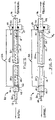
FIG. 1 is an enlarged scale longitudinally foreshortened schematic cross-sectional view through medical sensing catheter apparatus embodying principles of the present invention; -
FIG. 2 is a longitudinally foreshortened schematic cross-sectional view through a telescope section of the catheter apparatus with an inner telescope portion of the section being in its fully retracted position; and -
FIG. 3 is a view similar to that inFIG. 2 but with the inner telescope portion of the telescope section being in its fully extended position. - A
catheter 10 embodying principles of the present invention is schematically depicted inFIGS. 1-3 . By way of non-limiting example, thecatheter apparatus 10 is a medical sensing catheter, and more specifically is an intravascular ultrasound (IVUS) imaging catheter.Catheter 10 includes an elongated flexibletubular assembly 12 that circumscribes an elongated flexible drive shaft orcable 14 having anultrasound sensor 16 on itsdistal end 18.Drive cable 14 is illustratively of a conventional helically wound wire construction. - The
tubular assembly 12 that circumscribes thedrive cable 14 and thesensor 16 includes asheath 20 having aproximal end 21, and adistal end 22 insertable into the body of a patient, and a telescope section 24 (seeFIGS. 2 and 3 ) that facilitates movement of thedrive cable 14 distally and proximally through thesheath 20 while it remains stationary within the patient's body. Selective rotation and translation of thedrive cable 14 relative to thesheath 20 is effected by a conventional, schematically depicted translational/rotational drive mechanism 26 (FIG. 1 ) that may be selectively translated in distal and proximal directions as respectively illustrated byarrows 28,30 inFIG. 1 . Thedrive mechanism 26 is operatively coupled to theproximal end 32 of thedrive cable 14 and functions in a conventional manner to translate and rotate thedrive cable 14. -
Telescope section 24 includes an elongated flexible tubular outer catheter ortelescope member 34 having adistal end 36 fixedly secured to anannular coupling 38 that circumscribes and is fixedly secured to a longitudinally intermediate portion of thesheath 20. Theproximal end 40 of theouter telescope member 34 is anchored to a schematically depictedstationary support structure 42 distally positioned relative to thedrive mechanism 26. Thetelescope section 24 further includes an elongated flexible tubular inner catheter ortelescope member 44 which has distal andproximal ends Proximal end 48 is secured to thedrive mechanism 26, and theinner telescope member 44 slidably extends through an O-ring seal member 50 carried by thestationary support structure 42 which may be of a conventional construction and may be assembled around the O-ring 50. - According to a feature of the present invention the O-
ring seal 50 is formed of a self-lubricating material, representatively a fluoroelastomeric material. The use of a self-lubricating seal member substantially facilitates and quickens the assembly of thesupport structure 42 by eliminating the necessity of lubricating the seal and one or more of the support structure parts prior to using thesupport structure 42. - As shown in
FIGS. 1-3 , theinner telescope member 44 is distally telescoped into the outertelescope member portion 34 of the overalltubular assembly 12 for translation relative thereto (by means of the drive mechanism 26) between a retracted position shown inFIG. 2 (in which thesensor 16 is distally advanced within the sheath 20) and an extended position shown inFIG. 3 (in which the sensor is proximally retracted within the sheath 20). - According to a further feature of the present invention, a
proximal end portion 20a of thesheath 20 extends through thecoupling 38 into the interior of theouter telescope member 34 and proximally telescopes into the distal end of theinner telescope member 44 within thetelescope section 24. Thus theproximal sheath section 20a directly supports the portion of theflexible drive cable 14 within thetelescope section 24 whether theinner telescope member 44 is in its retracted position, its extended position, or any position therebetween. - This support for the portion of the
flexible drive cable 14 within thetelescope section 24, that prevents potential buckling of such cable portion when thedrive cable 14 is being distally pushed by theinner telescope member 44 as it is moved toward its retracted position, is desirably achieved without the previous additional manufacturing and assembly cost of providing and installing a separate support structure within thetelescope section 24. In the present invention this cable support function is uniquely provided using a longitudinal portion of thesheath 20 which may be simply furnished in a bit longer length to form thecable support portion 20a thereof. Illustratively, thesheath 20 is of a continuous one piece construction, and need not be modified in any manner other than the illustrated lengthening. - While the
catheter 10 has been representatively illustrated as being an IVUS catheter, it will be readily appreciated by those of ordinary skill in this particular art that other types of catheter structures with flexible internal drive shafts or cables and associated telescope sections may advantageously incorporate the above-described type of cable support without departing from principles of the present invention. Such other types of catheter structures include, for example, photo-acoustic, optical coherence tomography, phased array/multiple transducer, and spectroscopic systems.
Claims (8)
- A catheter apparatus (10) comprising:an elongated flexible tubing assembly (12) having a telescope section (24), the telescope section including a tubular outer telescope member (34) having proximal and distal ends (40, 36), a tubular inner telescope member (44) longitudinally movable through the interior of said outer telescope member toward and away from said distal end thereof, and a sheath member (20) anchored to said outer telescope member and having a proximal end portion (20a) extending proximally through said outer telescope member and telescopingly received in said inner telescope member; andan elongated flexible drive member (14) movable relative to said flexible tubing assembly and extending through said outer telescope member and said inner telescope member and being supported within said outer telescope member by said proximal end portion of said sheath,characterized in that a portion of said inner telescope member (44) is slidingly supported within a self-lubricating O-ring member (50) carried by a support structure (42) anchored to the proximal end (40) of the outer telescope member (34).
- The catheter apparatus of claim 1, wherein said catheter apparatus is a medical sensing catheter.
- The catheter apparatus of claim 2, wherein said medical sensing catheter apparatus is an IVUS catheter and further comprises an ultrasound sensor (16) carried on a distal end (18) of said elongated flexible drive member.
- The catheter apparatus of claim 3, wherein the elongated flexible drive member is operable to rotate the ultrasound sensor.
- The catheter apparatus of claim 2, wherein said medical sensing catheter further comprises one of a photo-acoustic system, an optical coherence tomography system, a phased array/multiple transducer system, and a spectroscopic system.
- The catheter apparatus of any preceding claim, wherein said flexible drive member is of a helically wound wire construction.
- The catheter apparatus of any preceding claim, wherein said sheath is of a joint-free configuration from its distal end to its proximal end.
- The catheter apparatus of any preceding claim, wherein said self-lubricating O-ring is of a fluoroelastomeric material.
Priority Applications (1)
| Application Number | Priority Date | Filing Date | Title |
|---|---|---|---|
| EP22201528.1A EP4151156A1 (en) | 2012-12-13 | 2013-12-11 | Rotational catheter with extended catheter body drive shaft support |
Applications Claiming Priority (2)
| Application Number | Priority Date | Filing Date | Title |
|---|---|---|---|
| US201261736666P | 2012-12-13 | 2012-12-13 | |
| PCT/US2013/074358 WO2014093472A1 (en) | 2012-12-13 | 2013-12-11 | Rotational catheter with extended catheter body drive shaft support |
Related Child Applications (1)
| Application Number | Title | Priority Date | Filing Date |
|---|---|---|---|
| EP22201528.1A Division EP4151156A1 (en) | 2012-12-13 | 2013-12-11 | Rotational catheter with extended catheter body drive shaft support |
Publications (3)
| Publication Number | Publication Date |
|---|---|
| EP2931131A1 EP2931131A1 (en) | 2015-10-21 |
| EP2931131A4 EP2931131A4 (en) | 2016-08-17 |
| EP2931131B1 true EP2931131B1 (en) | 2022-11-09 |
Family
ID=50931711
Family Applications (2)
| Application Number | Title | Priority Date | Filing Date |
|---|---|---|---|
| EP22201528.1A Pending EP4151156A1 (en) | 2012-12-13 | 2013-12-11 | Rotational catheter with extended catheter body drive shaft support |
| EP13862021.6A Active EP2931131B1 (en) | 2012-12-13 | 2013-12-11 | Rotational catheter with extended catheter body drive shaft support |
Family Applications Before (1)
| Application Number | Title | Priority Date | Filing Date |
|---|---|---|---|
| EP22201528.1A Pending EP4151156A1 (en) | 2012-12-13 | 2013-12-11 | Rotational catheter with extended catheter body drive shaft support |
Country Status (5)
| Country | Link |
|---|---|
| US (1) | US10448922B2 (en) |
| EP (2) | EP4151156A1 (en) |
| JP (2) | JP2016501091A (en) |
| CA (1) | CA2895173A1 (en) |
| WO (1) | WO2014093472A1 (en) |
Cited By (3)
| Publication number | Priority date | Publication date | Assignee | Title |
|---|---|---|---|---|
| US11648424B2 (en) | 2018-11-28 | 2023-05-16 | Histosonics Inc. | Histotripsy systems and methods |
| US11813485B2 (en) | 2020-01-28 | 2023-11-14 | The Regents Of The University Of Michigan | Systems and methods for histotripsy immunosensitization |
| US11819712B2 (en) | 2013-08-22 | 2023-11-21 | The Regents Of The University Of Michigan | Histotripsy using very short ultrasound pulses |
Families Citing this family (12)
| Publication number | Priority date | Publication date | Assignee | Title |
|---|---|---|---|---|
| US10076272B2 (en) | 2011-04-26 | 2018-09-18 | Velano Vascular, Inc. | Systems and methods for phlebotomy through a peripheral IV catheter |
| US9186100B2 (en) | 2011-04-26 | 2015-11-17 | Velano Vascular, Inc. | Systems and methods for phlebotomy through a peripheral IV catheter |
| US8366685B2 (en) | 2011-04-26 | 2013-02-05 | Creative Vascular, Llc | Systems and methods for phlebotomy through a peripheral IV catheter |
| AU2015306728B2 (en) * | 2014-08-26 | 2020-05-07 | Velano Vascular, Inc. | Systems and methods for phlebotomy through a peripheral IV catheter |
| US10300247B2 (en) | 2016-02-03 | 2019-05-28 | Velano Vascular, Inc. | Devices and methods for fluid transfer through a placed peripheral intravenous catheter |
| US9744344B1 (en) | 2016-06-30 | 2017-08-29 | Velano Vascular, Inc. | Devices and methods for catheter placement within a vein |
| CN110430914B (en) | 2017-03-21 | 2022-03-01 | 威蓝诺血管股份有限公司 | Device for fluid delivery through a placed peripheral venous catheter |
| EP4059556A1 (en) | 2017-03-21 | 2022-09-21 | Velano Vascular, Inc. | Methods for controlling catheter device size |
| US10994098B2 (en) | 2017-09-20 | 2021-05-04 | St. Jude Medical, Cardiology Division, Inc. | Medical device including an actuator restraining assembly |
| WO2021035026A1 (en) | 2019-08-20 | 2021-02-25 | Velano Vascular, Inc. | Fluid transfer devices with extended length catheters and methods of using the same |
| MX2023006170A (en) | 2020-11-26 | 2023-06-08 | Avia Vascular Llc | Blood collection devices, systems, and methods. |
| WO2022246045A1 (en) * | 2021-05-19 | 2022-11-24 | Boston Scientific Scimed Inc. | Devices, systems, and methods for reducing signal noise in endoscopic rotational imaging |
Citations (1)
| Publication number | Priority date | Publication date | Assignee | Title |
|---|---|---|---|---|
| US20070021767A1 (en) * | 2005-07-25 | 2007-01-25 | Breznock Eugene M | Steerable endoluminal punch |
Family Cites Families (23)
| Publication number | Priority date | Publication date | Assignee | Title |
|---|---|---|---|---|
| US4381690A (en) * | 1981-03-02 | 1983-05-03 | Baldwin Piano & Organ Company | Cymbal stand |
| JPS57175351A (en) * | 1981-04-20 | 1982-10-28 | Olympus Optical Co | Ultrasonic diagnostic apparatus for body cavity |
| US4886507A (en) * | 1988-02-01 | 1989-12-12 | Medex, Inc. | Y connector for angioplasty procedure |
| US4951677A (en) * | 1988-03-21 | 1990-08-28 | Prutech Research And Development Partnership Ii | Acoustic imaging catheter and the like |
| DE4018638A1 (en) * | 1990-06-11 | 1991-12-12 | Schoppe & Faeser Gmbh | PRESSURE TRANSMITTER WITH A ROTATIONALLY SYMMETRICAL PRESSURE SENSOR MADE OF CERAMIC |
| DE4244990C2 (en) * | 1992-12-15 | 2002-03-14 | Stm Medtech Starnberg | Device for moving an endoscope shaft along a channel-like cavity |
| US5807237A (en) * | 1997-03-31 | 1998-09-15 | Tindel; Nathaniel L. | Endoscopic device |
| JP2000175917A (en) * | 1998-12-17 | 2000-06-27 | Terumo Corp | Ultrasonic transducer axially moving device and ultrasonic catheter diagnostic instrument |
| US6936045B2 (en) | 2001-09-20 | 2005-08-30 | Endocare, Inc. | Malleable cryosurgical probe |
| US7335180B2 (en) | 2003-11-24 | 2008-02-26 | Flowcardia, Inc. | Steerable ultrasound catheter |
| JP4721133B2 (en) * | 2003-05-09 | 2011-07-13 | アンジオメト・ゲーエムベーハー・ウント・コンパニー・メディツィンテクニク・カーゲー | Stent delivery system with radially stabilized catheter |
| US7833176B2 (en) * | 2003-08-13 | 2010-11-16 | G. I. View Ltd. | Pressure-propelled system for body lumen |
| US8104479B2 (en) * | 2005-06-23 | 2012-01-31 | Volcano Corporation | Pleated bag for interventional pullback systems |
| US9622706B2 (en) * | 2007-07-12 | 2017-04-18 | Volcano Corporation | Catheter for in vivo imaging |
| US8062226B2 (en) * | 2007-12-17 | 2011-11-22 | Silicon Valley Medical Instruments, Inc. | Telescope for an imaging catheter |
| US8277381B2 (en) * | 2007-12-21 | 2012-10-02 | Boston Scientific Scimed, Inc. | Low profile intravascular ultrasound catheter |
| CN102076265B (en) * | 2008-05-30 | 2014-10-01 | 戈尔企业控股股份有限公司 | Real time ultrasound catheter probe |
| US20100049099A1 (en) * | 2008-07-18 | 2010-02-25 | Vytronus, Inc. | Method and system for positioning an energy source |
| US8403856B2 (en) * | 2009-03-11 | 2013-03-26 | Volcano Corporation | Rotational intravascular ultrasound probe with an active spinning element |
| EP2456503B1 (en) * | 2009-07-23 | 2017-09-06 | Acist Medical Systems, Inc. | Endoventricular injection catheter system with integrated echocardiographic capabilities |
| JP5551397B2 (en) * | 2009-09-30 | 2014-07-16 | テルモ株式会社 | Diagnostic imaging catheter |
| JP5399301B2 (en) * | 2010-03-12 | 2014-01-29 | テルモ株式会社 | catheter |
| CA2878683C (en) * | 2012-07-12 | 2021-07-20 | President And Fellows Of Harvard College | Slippery self-lubricating polymer surfaces |
-
2013
- 2013-12-11 CA CA2895173A patent/CA2895173A1/en not_active Abandoned
- 2013-12-11 EP EP22201528.1A patent/EP4151156A1/en active Pending
- 2013-12-11 US US14/103,582 patent/US10448922B2/en active Active
- 2013-12-11 JP JP2015547493A patent/JP2016501091A/en active Pending
- 2013-12-11 WO PCT/US2013/074358 patent/WO2014093472A1/en active Application Filing
- 2013-12-11 EP EP13862021.6A patent/EP2931131B1/en active Active
-
2019
- 2019-12-04 JP JP2019219677A patent/JP6979633B2/en active Active
Patent Citations (1)
| Publication number | Priority date | Publication date | Assignee | Title |
|---|---|---|---|---|
| US20070021767A1 (en) * | 2005-07-25 | 2007-01-25 | Breznock Eugene M | Steerable endoluminal punch |
Cited By (4)
| Publication number | Priority date | Publication date | Assignee | Title |
|---|---|---|---|---|
| US11819712B2 (en) | 2013-08-22 | 2023-11-21 | The Regents Of The University Of Michigan | Histotripsy using very short ultrasound pulses |
| US11648424B2 (en) | 2018-11-28 | 2023-05-16 | Histosonics Inc. | Histotripsy systems and methods |
| US11813484B2 (en) | 2018-11-28 | 2023-11-14 | Histosonics, Inc. | Histotripsy systems and methods |
| US11813485B2 (en) | 2020-01-28 | 2023-11-14 | The Regents Of The University Of Michigan | Systems and methods for histotripsy immunosensitization |
Also Published As
| Publication number | Publication date |
|---|---|
| EP4151156A1 (en) | 2023-03-22 |
| WO2014093472A1 (en) | 2014-06-19 |
| CA2895173A1 (en) | 2014-06-19 |
| JP6979633B2 (en) | 2021-12-15 |
| JP2020039921A (en) | 2020-03-19 |
| EP2931131A1 (en) | 2015-10-21 |
| JP2016501091A (en) | 2016-01-18 |
| US10448922B2 (en) | 2019-10-22 |
| US20140171803A1 (en) | 2014-06-19 |
| EP2931131A4 (en) | 2016-08-17 |
Similar Documents
| Publication | Publication Date | Title |
|---|---|---|
| EP2931131B1 (en) | Rotational catheter with extended catheter body drive shaft support | |
| EP2931130B1 (en) | Rotational sensing catheter with self-supporting drive shaft section | |
| CN109068995B (en) | Imaging probe with rotatable core | |
| US10039522B2 (en) | Method and system for imaging, diagnosing, and/or treating an area of interest in a patient's body | |
| JP4065167B2 (en) | catheter | |
| EP2934653B1 (en) | Rotational ultrasound imaging catheter with extended catheter body telescope | |
| US10709312B2 (en) | Transitional region having cuts and a skive for an imaging catheter | |
| JP5662846B2 (en) | catheter | |
| JP2008535630A (en) | Imaging guidewire for forward observation | |
| US9492140B2 (en) | Devices, systems, and methods for forward looking imaging | |
| JP2001245886A (en) | Ultrasonic echo catheter within blood vessel | |
| JP2012217588A (en) | Medical device | |
| US20220133134A1 (en) | Imaging and pressure sensing apparatus and probes with a slidable sheath | |
| WO2013146196A1 (en) | Medical device |
Legal Events
| Date | Code | Title | Description |
|---|---|---|---|
| PUAI | Public reference made under article 153(3) epc to a published international application that has entered the european phase |
Free format text: ORIGINAL CODE: 0009012 |
|
| 17P | Request for examination filed |
Effective date: 20150522 |
|
| AK | Designated contracting states |
Kind code of ref document: A1 Designated state(s): AL AT BE BG CH CY CZ DE DK EE ES FI FR GB GR HR HU IE IS IT LI LT LU LV MC MK MT NL NO PL PT RO RS SE SI SK SM TR |
|
| AX | Request for extension of the european patent |
Extension state: BA ME |
|
| DAX | Request for extension of the european patent (deleted) | ||
| A4 | Supplementary search report drawn up and despatched |
Effective date: 20160719 |
|
| RIC1 | Information provided on ipc code assigned before grant |
Ipc: A61B 8/00 20060101ALI20160713BHEP Ipc: A61B 8/12 20060101AFI20160713BHEP |
|
| STAA | Information on the status of an ep patent application or granted ep patent |
Free format text: STATUS: EXAMINATION IS IN PROGRESS |
|
| 17Q | First examination report despatched |
Effective date: 20190711 |
|
| STAA | Information on the status of an ep patent application or granted ep patent |
Free format text: STATUS: EXAMINATION IS IN PROGRESS |
|
| RAP1 | Party data changed (applicant data changed or rights of an application transferred) |
Owner name: PHILIPS IMAGE GUIDED THERAPY CORPORATION |
|
| STAA | Information on the status of an ep patent application or granted ep patent |
Free format text: STATUS: EXAMINATION IS IN PROGRESS |
|
| GRAP | Despatch of communication of intention to grant a patent |
Free format text: ORIGINAL CODE: EPIDOSNIGR1 |
|
| STAA | Information on the status of an ep patent application or granted ep patent |
Free format text: STATUS: GRANT OF PATENT IS INTENDED |
|
| INTG | Intention to grant announced |
Effective date: 20220601 |
|
| GRAS | Grant fee paid |
Free format text: ORIGINAL CODE: EPIDOSNIGR3 |
|
| GRAA | (expected) grant |
Free format text: ORIGINAL CODE: 0009210 |
|
| STAA | Information on the status of an ep patent application or granted ep patent |
Free format text: STATUS: THE PATENT HAS BEEN GRANTED |
|
| AK | Designated contracting states |
Kind code of ref document: B1 Designated state(s): AL AT BE BG CH CY CZ DE DK EE ES FI FR GB GR HR HU IE IS IT LI LT LU LV MC MK MT NL NO PL PT RO RS SE SI SK SM TR |
|
| REG | Reference to a national code |
Ref country code: GB Ref legal event code: FG4D |
|
| REG | Reference to a national code |
Ref country code: CH Ref legal event code: EP Ref country code: AT Ref legal event code: REF Ref document number: 1529837 Country of ref document: AT Kind code of ref document: T Effective date: 20221115 |
|
| REG | Reference to a national code |
Ref country code: DE Ref legal event code: R096 Ref document number: 602013082852 Country of ref document: DE |
|
| REG | Reference to a national code |
Ref country code: IE Ref legal event code: FG4D |
|
| REG | Reference to a national code |
Ref country code: LT Ref legal event code: MG9D |
|
| REG | Reference to a national code |
Ref country code: NL Ref legal event code: MP Effective date: 20221109 |
|
| REG | Reference to a national code |
Ref country code: AT Ref legal event code: MK05 Ref document number: 1529837 Country of ref document: AT Kind code of ref document: T Effective date: 20221109 |
|
| PG25 | Lapsed in a contracting state [announced via postgrant information from national office to epo] |
Ref country code: SE Free format text: LAPSE BECAUSE OF FAILURE TO SUBMIT A TRANSLATION OF THE DESCRIPTION OR TO PAY THE FEE WITHIN THE PRESCRIBED TIME-LIMIT Effective date: 20221109 Ref country code: PT Free format text: LAPSE BECAUSE OF FAILURE TO SUBMIT A TRANSLATION OF THE DESCRIPTION OR TO PAY THE FEE WITHIN THE PRESCRIBED TIME-LIMIT Effective date: 20230309 Ref country code: NO Free format text: LAPSE BECAUSE OF FAILURE TO SUBMIT A TRANSLATION OF THE DESCRIPTION OR TO PAY THE FEE WITHIN THE PRESCRIBED TIME-LIMIT Effective date: 20230209 Ref country code: LT Free format text: LAPSE BECAUSE OF FAILURE TO SUBMIT A TRANSLATION OF THE DESCRIPTION OR TO PAY THE FEE WITHIN THE PRESCRIBED TIME-LIMIT Effective date: 20221109 Ref country code: FI Free format text: LAPSE BECAUSE OF FAILURE TO SUBMIT A TRANSLATION OF THE DESCRIPTION OR TO PAY THE FEE WITHIN THE PRESCRIBED TIME-LIMIT Effective date: 20221109 Ref country code: ES Free format text: LAPSE BECAUSE OF FAILURE TO SUBMIT A TRANSLATION OF THE DESCRIPTION OR TO PAY THE FEE WITHIN THE PRESCRIBED TIME-LIMIT Effective date: 20221109 Ref country code: AT Free format text: LAPSE BECAUSE OF FAILURE TO SUBMIT A TRANSLATION OF THE DESCRIPTION OR TO PAY THE FEE WITHIN THE PRESCRIBED TIME-LIMIT Effective date: 20221109 |
|
| PG25 | Lapsed in a contracting state [announced via postgrant information from national office to epo] |
Ref country code: RS Free format text: LAPSE BECAUSE OF FAILURE TO SUBMIT A TRANSLATION OF THE DESCRIPTION OR TO PAY THE FEE WITHIN THE PRESCRIBED TIME-LIMIT Effective date: 20221109 Ref country code: PL Free format text: LAPSE BECAUSE OF FAILURE TO SUBMIT A TRANSLATION OF THE DESCRIPTION OR TO PAY THE FEE WITHIN THE PRESCRIBED TIME-LIMIT Effective date: 20221109 Ref country code: LV Free format text: LAPSE BECAUSE OF FAILURE TO SUBMIT A TRANSLATION OF THE DESCRIPTION OR TO PAY THE FEE WITHIN THE PRESCRIBED TIME-LIMIT Effective date: 20221109 Ref country code: IS Free format text: LAPSE BECAUSE OF FAILURE TO SUBMIT A TRANSLATION OF THE DESCRIPTION OR TO PAY THE FEE WITHIN THE PRESCRIBED TIME-LIMIT Effective date: 20230309 Ref country code: HR Free format text: LAPSE BECAUSE OF FAILURE TO SUBMIT A TRANSLATION OF THE DESCRIPTION OR TO PAY THE FEE WITHIN THE PRESCRIBED TIME-LIMIT Effective date: 20221109 Ref country code: GR Free format text: LAPSE BECAUSE OF FAILURE TO SUBMIT A TRANSLATION OF THE DESCRIPTION OR TO PAY THE FEE WITHIN THE PRESCRIBED TIME-LIMIT Effective date: 20230210 |
|
| PGFP | Annual fee paid to national office [announced via postgrant information from national office to epo] |
Ref country code: DE Payment date: 20221227 Year of fee payment: 10 |
|
| PG25 | Lapsed in a contracting state [announced via postgrant information from national office to epo] |
Ref country code: NL Free format text: LAPSE BECAUSE OF FAILURE TO SUBMIT A TRANSLATION OF THE DESCRIPTION OR TO PAY THE FEE WITHIN THE PRESCRIBED TIME-LIMIT Effective date: 20221109 |
|
| PG25 | Lapsed in a contracting state [announced via postgrant information from national office to epo] |
Ref country code: SM Free format text: LAPSE BECAUSE OF FAILURE TO SUBMIT A TRANSLATION OF THE DESCRIPTION OR TO PAY THE FEE WITHIN THE PRESCRIBED TIME-LIMIT Effective date: 20221109 Ref country code: RO Free format text: LAPSE BECAUSE OF FAILURE TO SUBMIT A TRANSLATION OF THE DESCRIPTION OR TO PAY THE FEE WITHIN THE PRESCRIBED TIME-LIMIT Effective date: 20221109 Ref country code: EE Free format text: LAPSE BECAUSE OF FAILURE TO SUBMIT A TRANSLATION OF THE DESCRIPTION OR TO PAY THE FEE WITHIN THE PRESCRIBED TIME-LIMIT Effective date: 20221109 Ref country code: DK Free format text: LAPSE BECAUSE OF FAILURE TO SUBMIT A TRANSLATION OF THE DESCRIPTION OR TO PAY THE FEE WITHIN THE PRESCRIBED TIME-LIMIT Effective date: 20221109 Ref country code: CZ Free format text: LAPSE BECAUSE OF FAILURE TO SUBMIT A TRANSLATION OF THE DESCRIPTION OR TO PAY THE FEE WITHIN THE PRESCRIBED TIME-LIMIT Effective date: 20221109 |
|
| REG | Reference to a national code |
Ref country code: CH Ref legal event code: PL |
|
| REG | Reference to a national code |
Ref country code: DE Ref legal event code: R097 Ref document number: 602013082852 Country of ref document: DE |
|
| REG | Reference to a national code |
Ref country code: BE Ref legal event code: MM Effective date: 20221231 |
|
| PG25 | Lapsed in a contracting state [announced via postgrant information from national office to epo] |
Ref country code: SK Free format text: LAPSE BECAUSE OF FAILURE TO SUBMIT A TRANSLATION OF THE DESCRIPTION OR TO PAY THE FEE WITHIN THE PRESCRIBED TIME-LIMIT Effective date: 20221109 Ref country code: LU Free format text: LAPSE BECAUSE OF NON-PAYMENT OF DUE FEES Effective date: 20221211 Ref country code: AL Free format text: LAPSE BECAUSE OF FAILURE TO SUBMIT A TRANSLATION OF THE DESCRIPTION OR TO PAY THE FEE WITHIN THE PRESCRIBED TIME-LIMIT Effective date: 20221109 |
|
| PLBE | No opposition filed within time limit |
Free format text: ORIGINAL CODE: 0009261 |
|
| STAA | Information on the status of an ep patent application or granted ep patent |
Free format text: STATUS: NO OPPOSITION FILED WITHIN TIME LIMIT |
|
| 26N | No opposition filed |
Effective date: 20230810 |
|
| PG25 | Lapsed in a contracting state [announced via postgrant information from national office to epo] |
Ref country code: LI Free format text: LAPSE BECAUSE OF NON-PAYMENT OF DUE FEES Effective date: 20221231 Ref country code: IE Free format text: LAPSE BECAUSE OF NON-PAYMENT OF DUE FEES Effective date: 20221211 Ref country code: CH Free format text: LAPSE BECAUSE OF NON-PAYMENT OF DUE FEES Effective date: 20221231 |
|
| PG25 | Lapsed in a contracting state [announced via postgrant information from national office to epo] |
Ref country code: SI Free format text: LAPSE BECAUSE OF FAILURE TO SUBMIT A TRANSLATION OF THE DESCRIPTION OR TO PAY THE FEE WITHIN THE PRESCRIBED TIME-LIMIT Effective date: 20221109 Ref country code: FR Free format text: LAPSE BECAUSE OF NON-PAYMENT OF DUE FEES Effective date: 20230109 Ref country code: BE Free format text: LAPSE BECAUSE OF NON-PAYMENT OF DUE FEES Effective date: 20221231 |
|
| PGFP | Annual fee paid to national office [announced via postgrant information from national office to epo] |
Ref country code: GB Payment date: 20231219 Year of fee payment: 11 |
|
| PG25 | Lapsed in a contracting state [announced via postgrant information from national office to epo] |
Ref country code: HU Free format text: LAPSE BECAUSE OF FAILURE TO SUBMIT A TRANSLATION OF THE DESCRIPTION OR TO PAY THE FEE WITHIN THE PRESCRIBED TIME-LIMIT; INVALID AB INITIO Effective date: 20131211 |