JP2016501091A - Rotating catheter including extended catheter body drive shaft support - Google Patents
Rotating catheter including extended catheter body drive shaft support Download PDFInfo
- Publication number
- JP2016501091A JP2016501091A JP2015547493A JP2015547493A JP2016501091A JP 2016501091 A JP2016501091 A JP 2016501091A JP 2015547493 A JP2015547493 A JP 2015547493A JP 2015547493 A JP2015547493 A JP 2015547493A JP 2016501091 A JP2016501091 A JP 2016501091A
- Authority
- JP
- Japan
- Prior art keywords
- catheter
- nesting
- distal end
- sheath
- catheter device
- Prior art date
- Legal status (The legal status is an assumption and is not a legal conclusion. Google has not performed a legal analysis and makes no representation as to the accuracy of the status listed.)
- Pending
Links
Images

Classifications
-
- A—HUMAN NECESSITIES
- A61—MEDICAL OR VETERINARY SCIENCE; HYGIENE
- A61B—DIAGNOSIS; SURGERY; IDENTIFICATION
- A61B8/00—Diagnosis using ultrasonic, sonic or infrasonic waves
- A61B8/44—Constructional features of the ultrasonic, sonic or infrasonic diagnostic device
- A61B8/4444—Constructional features of the ultrasonic, sonic or infrasonic diagnostic device related to the probe
- A61B8/4461—Features of the scanning mechanism, e.g. for moving the transducer within the housing of the probe
-
- A—HUMAN NECESSITIES
- A61—MEDICAL OR VETERINARY SCIENCE; HYGIENE
- A61B—DIAGNOSIS; SURGERY; IDENTIFICATION
- A61B8/00—Diagnosis using ultrasonic, sonic or infrasonic waves
- A61B8/12—Diagnosis using ultrasonic, sonic or infrasonic waves in body cavities or body tracts, e.g. by using catheters
-
- A—HUMAN NECESSITIES
- A61—MEDICAL OR VETERINARY SCIENCE; HYGIENE
- A61B—DIAGNOSIS; SURGERY; IDENTIFICATION
- A61B8/00—Diagnosis using ultrasonic, sonic or infrasonic waves
- A61B8/44—Constructional features of the ultrasonic, sonic or infrasonic diagnostic device
- A61B8/4444—Constructional features of the ultrasonic, sonic or infrasonic diagnostic device related to the probe
- A61B8/445—Details of catheter construction
Abstract
回転血管内カテーテルでは、内部にカテーテルの細長い柔軟なドライブ部材が移動可能に配置されるカテーテルシースの近位部分が、カテーテルの入れ子部分内に延ばされる。近位シース箇所は、入れ子箇所が、延伸位置にあるか、後退位置にあるか、又はそれらの間の任意の位置にあるかにかかわらず、入れ子箇所内に配置されたドライブ部材の箇所を支持するべく機能する。In a rotating intravascular catheter, the proximal portion of the catheter sheath within which the elongated flexible drive member of the catheter is movably disposed is extended into the nested portion of the catheter. The proximal sheath location supports the location of the drive member located within the nesting location, regardless of whether the nesting location is in the extended position, the retracted position, or any position therebetween. It works as much as you can.
Description
本開示の実施形態は、概して医療機器の分野に関するものであり、より具体的には、体内の血管診断法に使用されるカテーテル装置に関するものである。 Embodiments of the present disclosure relate generally to the field of medical devices, and more specifically to catheter devices used for intravascular blood vessel diagnostics.
近年は、血管内超音波(IVUS)イメージングを用いることにより、血管閉塞の構造を可視化するための様々な技術及びシステムが開発されている。IVUS技術は、カテーテルをベースとし、動脈内腔および動脈壁のリアルタイムの断面像をもたらすものである。IVUSカテーテルは、カテーテルの遠位端部に、一以上の超音波振動子を含むものであり、それにより、検査中の動脈の断面情報を含む画像を決定することができる。IVUSイメージングは、閉塞物の構造ならびに、様々な度合いで、動脈壁の中間層および血管内膜の境界の可視化を可能にする。 In recent years, various techniques and systems have been developed to visualize the structure of vascular occlusions by using intravascular ultrasound (IVUS) imaging. IVUS technology is catheter-based and provides real-time cross-sectional images of arterial lumens and arterial walls. An IVUS catheter includes one or more ultrasound transducers at the distal end of the catheter, which can determine an image that includes cross-sectional information of the artery under examination. IVUS imaging allows visualization of the structure of the occlusion and, to varying degrees, the middle layer of the arterial wall and the boundary of the intima.
IVUSイメージングカテーテル・システムの一般的なタイプは通常、カテーテルの遠位端における単一の振動子が、高速(約2000rpm未満)で回転して、急速な一連の360度の超音波スイープ(a rapid series of 360-degree ultrasound sweeps)を生成する構成を含む。そのような速度は、毎秒約30未満の画像の生成をもたらし、これは、病変動脈のリアルタイム画像を効果的に提示する。 A common type of IVUS imaging catheter system is usually a single transducer at the distal end of the catheter rotating at a high speed (less than about 2000 rpm) to produce a rapid series of 360 degree ultrasonic sweeps (a rapid series of 360-degree ultrasound sweeps). Such speed results in the generation of less than about 30 images per second, which effectively presents a real-time image of the diseased artery.
振動子は、カテーテルの近位端でモーター駆動装置に接続されるドライブシャフトもしくはケーブルの端に取り付けられる。回転する振動子は、超音波に干渉せず、かつ高速回転するドライブシャフトから動脈を保護するシース内に収納される。それ故に、IVUSイメージング(または「センシング」)カテーテルは、従来の血管造影法技術を用いて、閉塞の領域へ前進させることができ、そしてその後、動脈壁の中間層及び血管内膜及び閉塞物を含む動脈壁における血管内腔のリアルタイム断面像をもたらすべく操作されることができる。体の部分の内部構造を可視化するために使用するカテーテルベースのシステムの他のタイプでは、細長いドリフトシャフト構造に配置されて、シースに包まれた可動センシング/イメージング要素を実装するものもまた知られており、これには、光音響、光コヒーレンス・トモグラフィー、位相配列/複合振動子および、分光システムが含まれる。 The transducer is attached to the end of a drive shaft or cable that is connected to the motor drive at the proximal end of the catheter. The rotating transducer is housed in a sheath that does not interfere with the ultrasonic wave and protects the artery from the drive shaft that rotates at high speed. Thus, IVUS imaging (or “sensing”) catheters can be advanced to the area of occlusion using conventional angiography techniques and then the arterial wall middle layer and the intima and obstructions It can be manipulated to provide a real-time cross-sectional view of the vessel lumen in the containing arterial wall. Other types of catheter-based systems used to visualize internal structures of body parts are also known that implement movable sensing / imaging elements encased in an elongated drift shaft structure and wrapped in a sheath. This includes photoacoustics, optical coherence tomography, phased array / composite transducers, and spectroscopic systems.
これらの代表的なタイプの医療センシングカテーテルは、管アセンブリを備え、それを通って、ドライブケーブルが移動可能に延びる。管アセンブリは通常、患者内に挿入可能なシースを含むとともに、入れ子箇所に固定される近位端を有するものであり、これは、ドライブケーブル及び、それによるセンサーが、患者の体内で静止している挿入されたシースの内部を経由して、患者の体内を通って選択的に移動することを許容する。入れ子箇所は、シースの近位端が支持されるその遠位端に、管状外側カテーテルもしくは入れ子部材を備える。入れ子箇所はまた、管状内側カテーテルもしくは入れ子部材を有し、これは、その近位端を通って外側入れ子部材の内部に嵌まり込むとともに、外側入れ子部材に対し、後退位置と延伸位置との間で、外側入れ子部材の内部を通って移動可能なものである。ドライブケーブルは、内側入れ子部材に固定されて、それとともに外側カテーテル部材に対して長手方向に移動する。 These exemplary types of medical sensing catheters include a tube assembly through which a drive cable extends. The tube assembly typically includes a sheath that is insertable into the patient and has a proximal end that is secured to the nesting point so that the drive cable and thereby the sensor is stationary within the patient's body. Allows selective movement through the patient's body via the inside of the inserted sheath. The nesting point comprises a tubular outer catheter or nesting member at its distal end where the proximal end of the sheath is supported. The nesting point also has a tubular inner catheter or nesting member that fits into the outer nesting member through its proximal end and between the retracted and extended positions relative to the outer nesting member. Thus, it is movable through the inside of the outer nesting member. The drive cable is secured to the inner nesting member and moves with it longitudinally relative to the outer catheter member.
内側入れ子部材の、その後退位置へ向かう遠位側の遠位移動は、シースを通して、ドライブケーブル及びセンサーを押し、また、内側入れ子部材の、その延伸位置へ向かう近位移動は、シースを通して、ドライブケーブル及びセンサーを引き戻す。内側入れ子部材が、その延伸位置に移動されたとき、外側入れ子部材の遠位端と内側カテーテル部材の遠位端との間で、外側カテーテル部材の内部を通って延びるドライブケーブルの位置は、実質的に入れ子箇所内に支持されず拘束されない。 Distal distal movement of the inner nesting member toward its retracted position pushes the drive cable and sensor through the sheath, and proximal movement of the inner nesting member toward its extended position drives through the sheath. Pull back the cable and sensor. When the inner nesting member is moved to its extended position, the position of the drive cable extending through the interior of the outer catheter member between the distal end of the outer nesting member and the distal end of the inner catheter member is substantially Therefore, it is not supported and restrained in the nesting part.
内側入れ子部材の、その後退位置へ遠位側に向かうその後の移動に応じて、ドライブケーブルの、露出して支持されない部分は、望ましくない態様で、入れ子箇所内での座屈が引き起こされることがあり、それにより、シースを通るドライブケーブルの望ましい遠位前進を妨げるとともに、また、ケーブル損傷の可能性がある。このドライブケーブル座屈の可能性の問題に対してこれまでに提案された解決策は、入れ子箇所内に別個の補強構造を配置し、内側入れ子部材が、その後退位置から離れて移動される際に、入れ子箇所を通って延びるドライブケーブルの位置を支持することであった。 In response to subsequent movement of the inner nesting member distally to its retracted position, the exposed and unsupported portion of the drive cable may cause buckling within the nesting site in an undesirable manner. Yes, thereby preventing the desired distal advancement of the drive cable through the sheath and also the potential for cable damage. Previously proposed solutions to this drive cable buckling problem place a separate reinforcement structure in the nesting point and the inner nesting member is moved away from its retracted position. And supporting the position of the drive cable extending through the nesting point.
しかしながら、これまでに提案されたこのドライブケーブル支持技術は、少なくとも一の追加のコンポーネントを、全体のカテーテルアセンブリ内に与えるとともに設置する必要があり、それにより、カテーテルアセンブリのコスト、複雑さ及び製造時間を望ましくなく増大させるので、完全に満足のいくものではないことが解かった。前述したところから容易に理解できるように、上述したカテーテル・ドライブケーブル座屈問題に対しては、改善された解決策の必要性がある。本発明の主な目的は、この必要性にある。 However, this previously proposed drive cable support technique requires that at least one additional component be provided and installed within the entire catheter assembly, thereby reducing the cost, complexity and manufacturing time of the catheter assembly. Has been found to be unsatisfactory because it undesirably increases. As can be readily appreciated from the foregoing, there is a need for an improved solution to the catheter drive cable buckling problem described above. This is the main object of the present invention.
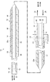
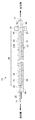
図1〜3に、本発明の原理を具体化したカテーテル10を概略的に描く。非限定的な例として、カテーテル装置10は、医療用センシングカテーテルであり、より具体的には、血管内超音波(IVUS)イメージングカテーテルである。カテーテル10は、細長い柔軟なドライブシャフトもしくはケーブル14を取り囲む柔軟な管状アセンブリ12を含むものであり、このドライブシャフトもしくはケーブル14は、その遠位端18に、超音波センサー16を有する。ドライブケーブル14は、例示的に、従来の螺旋巻きワイヤー構造である。
1-3 schematically depict a
ドライブケーブル14及びセンサー16を取り囲む管状アセンブリ12は、シース20を含み、シース20は、近位端21と、患者の体内に挿入可能な遠位端22と、患者の体内で静止している間に、シース20を通るドライブケーブル14の遠位側及び近位側の移動を促進させる入れ子箇所(a telescope section)24(図2及び3参照)とを有する。シース20に対するドライブケーブル14の選択的な回転及び並進は、従来の、概略的に描く並進/回転駆動機構26(図1)により達成され、これは、図1に矢印28、30でそれぞれ示すように、遠位及び近位方向に選択的に並進されることができる。駆動機構26は、ドライブケーブル14の近位端32に作動可能に連結され、ドライブケーブル14を並進及び回転させる従来の方法で機能する。
入れ子箇所24は、環状連結器38に強固に固定される遠位端36を有する細長い柔軟な管状外側カテーテルもしくは入れ子部材34を含み、環状連結器38は、シース20の長手方向中間部分を取り囲むとともにそれに強固に固定される。外側入れ子部材34の近位端40は、駆動機構26に対して遠位側に配置される、概略的に描いた固定支持構造42に支持される。入れ子箇所24は、遠位及び近位端46、48を有する細長い柔軟な管状内側カテーテルもしくは入れ子部材44をさらに含む。近位端48は、駆動機構26に固定され、また、内側入れ子部材44は、固定支持構造42により保持されるOリングシール部材50を通って、スライド可能に延び、これは、従来の構成のものとすることができるとともに、Oリング50の周囲に組み立てられ得る。
The
本発明の特徴によれば、Oリングシール50は、自己潤滑性材料、典型的にはフルオロエラストマー材料から形成される。自己潤滑性シール部材を使用することは、支持構造42を使用するに先立ち、一以上の支持構造42の部分及びシールを潤滑することの必要性を取り除くことにより、支持構造42の組み立てを実質的に促進させるとともに速める。
According to a feature of the present invention, O-
図1〜3に示すように、内側入れ子部材44は、全体の管状アセンブリ12の外側入れ子部材の部分34内に遠位側で嵌め込まれ、これは、図2に示す後退位置(ここでは、センサー16がシース20内で遠位側に前進される)と、図3に示す延伸位置(ここでは、センサーがシース20内で近位側に後退される)との間で、(駆動機構26により)それに対して並進するためである。
As shown in FIGS. 1-3, the
本発明のさらなる特徴によれば、シース20の近位端部20aは、連結器38を通って
外側入れ子部材34の内部に延びるとともに、近位側において、入れ子箇所24内で内側入れ子部材44の遠位端内に嵌まり込む。それにより、内側入れ子部材44が、その後退位置にあるか、延伸位置にあるか、または、それらの間の任意の位置にあるかにかかわらず、近位シース箇所20aは、入れ子箇所24内で柔軟なドライブケーブル14の部分を直接的に支持する。
According to a further feature of the present invention, the
入れ子箇所24内での柔軟なドライブケーブル14の部分のためのこの支持は、ドライブケーブル14が、その後退位置に向けて移動されつつ、内側入れ子部材44により遠位側に押されているときに、そのようなケーブル部分の潜在的な座屈を防止し、入れ子箇所24内で別個の支持構造を設けるとともに設置することの従来の追加の製造及び組立てコストなしに、望ましく達成することができる。本発明では、このケーブル支持機能は、単にケーブル支持部分20aを形成するために若干長い長さで与えられ得るシース20の長手方向部分を用いることにより特異的にもたらされる。例示としては、シース20は、連続的な一体構造であり、例示の延伸以外の任意の方法で変更されることを要しない。
This support for the portion of the
カテーテル10は、IVUSカテーテルであるとして典型的に説明したが、本発明の原理から逸脱することなく、柔軟な内部ドライブシャフトもしくはケーブル及び関連する入れ子箇所を有する他のタイプのカテーテル構造は、上述したタイプのケーブル支持を有利に包含し得ることが、この特定の技術における当業者には容易に理解される。そのような他のタイプのカテーテル構造は、たとえば、光音響、光コヒーレンス・トモグラフィー、位相配列/複合振動子及び、分光システムを含む。
Although the
Claims (8)
入れ子箇所を有する細長い柔軟な管アセンブリであって、該入れ子箇所が、近位端及び遠位端を有する管状の外側入れ子部材、前記外側入れ子部材の内部を通って、その前記遠位端に向けて、また該遠位端から離れて長手方向に移動可能な管状の内側入れ子部材、並びに、前記外側入れ子部材に支持されるとともに、前記外側入れ子部材を通って近位側に延び、かつ、前記内側入れ子部材内に嵌め込まれて収納されるシース部材を含む柔軟な管アセンブリと、
前記柔軟な管アセンブリに対して移動可能で、当該カテーテル、前記外側入れ子部材及び前記内側入れ子部材を通って延びるとともに、前記シースの近位端部により前記外側入れ子部材内に支持される細長い柔軟なドライブ部材と
を備えるカテーテル装置。 A catheter device,
An elongated flexible tube assembly having a nesting point, the nesting point being a tubular outer nesting member having a proximal end and a distal end, passing through the interior of the outer nesting member and toward the distal end A tubular inner nesting member movable longitudinally away from the distal end, and supported by the outer nesting member and extending proximally through the outer nesting member; and A flexible tube assembly including a sheath member that is fitted and housed within the inner nesting member;
An elongate flexible body movable relative to the flexible tube assembly and extending through the catheter, the outer nesting member and the inner nesting member and supported within the outer nesting member by a proximal end of the sheath. A catheter device comprising a drive member.
近位端及び遠位端を有する管状の外側カテーテル部材
当該外側管状カテーテル部材の前記遠位端から離れて遠位側に長手方向に延びるとともに前記外側カテーテル部材を通って延びる近位部分を有するシースと、
近位端及び遠位端を有する管状の内側カテーテル部材であって、前記内側カテーテル部材が、前記外側カテーテル部材内に、その前記近位端を通して嵌め込まれ、前記外側カテーテル部材に対し、前記外側カテーテル部材を通って後退位置と延伸位置との間で軸方向移動する内側カテーテル部材と、
前記外側カテーテル部材及び前記シースに対して移動可能で、かつ、それを通って延びる細長い柔軟なドライブ部材と
を備え、
前記シースの前記近位部分が、前記外側カテーテル部材内で、前記柔軟なドライブ部材を支持するとともに、前記内側カテーテル部材の前記遠位端内に嵌め込まれる医療用カテーテル装置。 A medical catheter device,
Tubular outer catheter member having a proximal end and a distal end A sheath having a proximal portion extending longitudinally distally away from the distal end of the outer tubular catheter member and extending through the outer catheter member When,
A tubular inner catheter member having a proximal end and a distal end, wherein the inner catheter member is fitted through the proximal end within the outer catheter member, with respect to the outer catheter member, the outer catheter An inner catheter member that moves axially between the retracted and extended positions through the member;
An elongate flexible drive member movable with respect to the outer catheter member and the sheath and extending therethrough,
A medical catheter device wherein the proximal portion of the sheath supports the flexible drive member within the outer catheter member and is fitted within the distal end of the inner catheter member.
Priority Applications (1)
| Application Number | Priority Date | Filing Date | Title |
|---|---|---|---|
| JP2019219677A JP6979633B2 (en) | 2012-12-13 | 2019-12-04 | Rotating catheter with extension catheter body drive shaft support |
Applications Claiming Priority (3)
| Application Number | Priority Date | Filing Date | Title |
|---|---|---|---|
| US201261736666P | 2012-12-13 | 2012-12-13 | |
| US61/736,666 | 2012-12-13 | ||
| PCT/US2013/074358 WO2014093472A1 (en) | 2012-12-13 | 2013-12-11 | Rotational catheter with extended catheter body drive shaft support |
Related Child Applications (1)
| Application Number | Title | Priority Date | Filing Date |
|---|---|---|---|
| JP2019219677A Division JP6979633B2 (en) | 2012-12-13 | 2019-12-04 | Rotating catheter with extension catheter body drive shaft support |
Publications (2)
| Publication Number | Publication Date |
|---|---|
| JP2016501091A true JP2016501091A (en) | 2016-01-18 |
| JP2016501091A5 JP2016501091A5 (en) | 2020-01-23 |
Family
ID=50931711
Family Applications (2)
| Application Number | Title | Priority Date | Filing Date |
|---|---|---|---|
| JP2015547493A Pending JP2016501091A (en) | 2012-12-13 | 2013-12-11 | Rotating catheter including extended catheter body drive shaft support |
| JP2019219677A Active JP6979633B2 (en) | 2012-12-13 | 2019-12-04 | Rotating catheter with extension catheter body drive shaft support |
Family Applications After (1)
| Application Number | Title | Priority Date | Filing Date |
|---|---|---|---|
| JP2019219677A Active JP6979633B2 (en) | 2012-12-13 | 2019-12-04 | Rotating catheter with extension catheter body drive shaft support |
Country Status (5)
| Country | Link |
|---|---|
| US (1) | US10448922B2 (en) |
| EP (2) | EP4151156A1 (en) |
| JP (2) | JP2016501091A (en) |
| CA (1) | CA2895173A1 (en) |
| WO (1) | WO2014093472A1 (en) |
Families Citing this family (15)
| Publication number | Priority date | Publication date | Assignee | Title |
|---|---|---|---|---|
| US9186100B2 (en) | 2011-04-26 | 2015-11-17 | Velano Vascular, Inc. | Systems and methods for phlebotomy through a peripheral IV catheter |
| US8366685B2 (en) | 2011-04-26 | 2013-02-05 | Creative Vascular, Llc | Systems and methods for phlebotomy through a peripheral IV catheter |
| US10076272B2 (en) | 2011-04-26 | 2018-09-18 | Velano Vascular, Inc. | Systems and methods for phlebotomy through a peripheral IV catheter |
| US10780298B2 (en) | 2013-08-22 | 2020-09-22 | The Regents Of The University Of Michigan | Histotripsy using very short monopolar ultrasound pulses |
| JP6527939B2 (en) * | 2014-08-26 | 2019-06-12 | ベラノ バスキュラー,インコーポレイテッド | Venous blood collection system and method with peripheral IV catheter |
| US10300247B2 (en) | 2016-02-03 | 2019-05-28 | Velano Vascular, Inc. | Devices and methods for fluid transfer through a placed peripheral intravenous catheter |
| US9744344B1 (en) | 2016-06-30 | 2017-08-29 | Velano Vascular, Inc. | Devices and methods for catheter placement within a vein |
| CA3052213A1 (en) | 2017-03-21 | 2018-09-27 | Velano Vascular, Inc. | Devices and methods for fluid transfer through a placed peripheral intravenous catheter |
| ES2921302T3 (en) | 2017-03-21 | 2022-08-23 | Velano Vascular Inc | Systems and methods for controlling catheter device size |
| US10994098B2 (en) | 2017-09-20 | 2021-05-04 | St. Jude Medical, Cardiology Division, Inc. | Medical device including an actuator restraining assembly |
| AU2019389001A1 (en) | 2018-11-28 | 2021-06-10 | Histosonics, Inc. | Histotripsy systems and methods |
| MX2022002125A (en) | 2019-08-20 | 2022-06-02 | Velano Vascular Inc | Fluid transfer devices with extended length catheters and methods of using the same. |
| US11813485B2 (en) | 2020-01-28 | 2023-11-14 | The Regents Of The University Of Michigan | Systems and methods for histotripsy immunosensitization |
| US20220161003A1 (en) | 2020-11-26 | 2022-05-26 | Avia Vascular, Llc | Blood collection devices, systems, and methods |
| US20220370036A1 (en) * | 2021-05-19 | 2022-11-24 | Boston Scientific Scimed Inc. | Boston scientific scimed inc. |
Citations (4)
| Publication number | Priority date | Publication date | Assignee | Title |
|---|---|---|---|---|
| JP2000175917A (en) * | 1998-12-17 | 2000-06-27 | Terumo Corp | Ultrasonic transducer axially moving device and ultrasonic catheter diagnostic instrument |
| US20090156941A1 (en) * | 2007-12-17 | 2009-06-18 | Silicon Valley Medical Instruments, Inc. | Telescope for an imaging catheter |
| JP2010533049A (en) * | 2007-07-12 | 2010-10-21 | ヴォルカノ コーポレイション | In vivo imaging catheter |
| US20110021911A1 (en) * | 2009-07-23 | 2011-01-27 | Silicon Valley Medical Instruments, Inc. | Endoventricular injection catheter system with integrated echocardiographic capabilities |
Family Cites Families (20)
| Publication number | Priority date | Publication date | Assignee | Title |
|---|---|---|---|---|
| US4381690A (en) * | 1981-03-02 | 1983-05-03 | Baldwin Piano & Organ Company | Cymbal stand |
| JPS57175351A (en) * | 1981-04-20 | 1982-10-28 | Olympus Optical Co | Ultrasonic diagnostic apparatus for body cavity |
| US4886507A (en) * | 1988-02-01 | 1989-12-12 | Medex, Inc. | Y connector for angioplasty procedure |
| US4951677A (en) * | 1988-03-21 | 1990-08-28 | Prutech Research And Development Partnership Ii | Acoustic imaging catheter and the like |
| DE4018638A1 (en) * | 1990-06-11 | 1991-12-12 | Schoppe & Faeser Gmbh | PRESSURE TRANSMITTER WITH A ROTATIONALLY SYMMETRICAL PRESSURE SENSOR MADE OF CERAMIC |
| DE4244990C2 (en) * | 1992-12-15 | 2002-03-14 | Stm Medtech Starnberg | Device for moving an endoscope shaft along a channel-like cavity |
| US5807237A (en) * | 1997-03-31 | 1998-09-15 | Tindel; Nathaniel L. | Endoscopic device |
| US6936045B2 (en) * | 2001-09-20 | 2005-08-30 | Endocare, Inc. | Malleable cryosurgical probe |
| US7335180B2 (en) * | 2003-11-24 | 2008-02-26 | Flowcardia, Inc. | Steerable ultrasound catheter |
| JP4721133B2 (en) * | 2003-05-09 | 2011-07-13 | アンジオメト・ゲーエムベーハー・ウント・コンパニー・メディツィンテクニク・カーゲー | Stent delivery system with radially stabilized catheter |
| US7833176B2 (en) * | 2003-08-13 | 2010-11-16 | G. I. View Ltd. | Pressure-propelled system for body lumen |
| US8104479B2 (en) * | 2005-06-23 | 2012-01-31 | Volcano Corporation | Pleated bag for interventional pullback systems |
| US20070021767A1 (en) * | 2005-07-25 | 2007-01-25 | Breznock Eugene M | Steerable endoluminal punch |
| US8277381B2 (en) | 2007-12-21 | 2012-10-02 | Boston Scientific Scimed, Inc. | Low profile intravascular ultrasound catheter |
| CN102076265B (en) * | 2008-05-30 | 2014-10-01 | 戈尔企业控股股份有限公司 | Real time ultrasound catheter probe |
| US20100049099A1 (en) * | 2008-07-18 | 2010-02-25 | Vytronus, Inc. | Method and system for positioning an energy source |
| US8403856B2 (en) | 2009-03-11 | 2013-03-26 | Volcano Corporation | Rotational intravascular ultrasound probe with an active spinning element |
| JP5551397B2 (en) * | 2009-09-30 | 2014-07-16 | テルモ株式会社 | Diagnostic imaging catheter |
| JP5399301B2 (en) * | 2010-03-12 | 2014-01-29 | テルモ株式会社 | catheter |
| CA2878683C (en) * | 2012-07-12 | 2021-07-20 | President And Fellows Of Harvard College | Slippery self-lubricating polymer surfaces |
-
2013
- 2013-12-11 EP EP22201528.1A patent/EP4151156A1/en active Pending
- 2013-12-11 JP JP2015547493A patent/JP2016501091A/en active Pending
- 2013-12-11 EP EP13862021.6A patent/EP2931131B1/en active Active
- 2013-12-11 CA CA2895173A patent/CA2895173A1/en not_active Abandoned
- 2013-12-11 WO PCT/US2013/074358 patent/WO2014093472A1/en active Application Filing
- 2013-12-11 US US14/103,582 patent/US10448922B2/en active Active
-
2019
- 2019-12-04 JP JP2019219677A patent/JP6979633B2/en active Active
Patent Citations (4)
| Publication number | Priority date | Publication date | Assignee | Title |
|---|---|---|---|---|
| JP2000175917A (en) * | 1998-12-17 | 2000-06-27 | Terumo Corp | Ultrasonic transducer axially moving device and ultrasonic catheter diagnostic instrument |
| JP2010533049A (en) * | 2007-07-12 | 2010-10-21 | ヴォルカノ コーポレイション | In vivo imaging catheter |
| US20090156941A1 (en) * | 2007-12-17 | 2009-06-18 | Silicon Valley Medical Instruments, Inc. | Telescope for an imaging catheter |
| US20110021911A1 (en) * | 2009-07-23 | 2011-01-27 | Silicon Valley Medical Instruments, Inc. | Endoventricular injection catheter system with integrated echocardiographic capabilities |
Also Published As
| Publication number | Publication date |
|---|---|
| WO2014093472A1 (en) | 2014-06-19 |
| EP2931131A1 (en) | 2015-10-21 |
| US10448922B2 (en) | 2019-10-22 |
| EP2931131B1 (en) | 2022-11-09 |
| JP2020039921A (en) | 2020-03-19 |
| CA2895173A1 (en) | 2014-06-19 |
| EP4151156A1 (en) | 2023-03-22 |
| EP2931131A4 (en) | 2016-08-17 |
| US20140171803A1 (en) | 2014-06-19 |
| JP6979633B2 (en) | 2021-12-15 |
Similar Documents
| Publication | Publication Date | Title |
|---|---|---|
| JP6979633B2 (en) | Rotating catheter with extension catheter body drive shaft support | |
| JP6353462B2 (en) | Rotating sensing catheter with self-supporting drive shaft location | |
| US10993694B2 (en) | Rotational ultrasound imaging catheter with extended catheter body telescope | |
| US8062226B2 (en) | Telescope for an imaging catheter | |
| CN109068995B (en) | Imaging probe with rotatable core | |
| JP5188242B2 (en) | In vivo insertion probe | |
| JP5679338B2 (en) | catheter | |
| US8905936B2 (en) | Catheter having a biasing member | |
| JP5662846B2 (en) | catheter | |
| JP2004097286A (en) | Catheter | |
| EP2934336B1 (en) | Transitional region having cuts and a skive for an imaging catheter | |
| JP7194733B2 (en) | Digital Rotation Patient Interface Module | |
| US20130331706A1 (en) | Devices, Systems, and Methods for Forward Looking Imaging | |
| JP2012217588A (en) | Medical device | |
| JP6779799B2 (en) | Medical device | |
| JP2023047206A (en) | Catheter for image diagnosis | |
| JP2023047207A (en) | Catheter for image diagnosis |
Legal Events
| Date | Code | Title | Description |
|---|---|---|---|
| A521 | Request for written amendment filed |
Free format text: JAPANESE INTERMEDIATE CODE: A523 Effective date: 20150817 |
|
| RD03 | Notification of appointment of power of attorney |
Free format text: JAPANESE INTERMEDIATE CODE: A7423 Effective date: 20160428 |
|
| A621 | Written request for application examination |
Free format text: JAPANESE INTERMEDIATE CODE: A621 Effective date: 20161206 |
|
| RD04 | Notification of resignation of power of attorney |
Free format text: JAPANESE INTERMEDIATE CODE: A7424 Effective date: 20161227 |
|
| RD04 | Notification of resignation of power of attorney |
Free format text: JAPANESE INTERMEDIATE CODE: A7424 Effective date: 20170214 |
|
| A131 | Notification of reasons for refusal |
Free format text: JAPANESE INTERMEDIATE CODE: A131 Effective date: 20170808 |
|
| A977 | Report on retrieval |
Free format text: JAPANESE INTERMEDIATE CODE: A971007 Effective date: 20170809 |
|
| A601 | Written request for extension of time |
Free format text: JAPANESE INTERMEDIATE CODE: A601 Effective date: 20171107 |
|
| A521 | Request for written amendment filed |
Free format text: JAPANESE INTERMEDIATE CODE: A523 Effective date: 20180208 |
|
| A02 | Decision of refusal |
Free format text: JAPANESE INTERMEDIATE CODE: A02 Effective date: 20180329 |
|
| A521 | Request for written amendment filed |
Free format text: JAPANESE INTERMEDIATE CODE: A523 Effective date: 20180727 |
|
| A911 | Transfer to examiner for re-examination before appeal (zenchi) |
Free format text: JAPANESE INTERMEDIATE CODE: A911 Effective date: 20180806 |
|
| A912 | Re-examination (zenchi) completed and case transferred to appeal board |
Free format text: JAPANESE INTERMEDIATE CODE: A912 Effective date: 20180824 |
|
| A601 | Written request for extension of time |
Free format text: JAPANESE INTERMEDIATE CODE: A601 Effective date: 20190829 |
|
| A524 | Written submission of copy of amendment under article 19 pct |
Free format text: JAPANESE INTERMEDIATE CODE: A524 Effective date: 20191204 |