WO2013136589A1 - 電動機 - Google Patents
電動機 Download PDFInfo
- Publication number
- WO2013136589A1 WO2013136589A1 PCT/JP2012/079553 JP2012079553W WO2013136589A1 WO 2013136589 A1 WO2013136589 A1 WO 2013136589A1 JP 2012079553 W JP2012079553 W JP 2012079553W WO 2013136589 A1 WO2013136589 A1 WO 2013136589A1
- Authority
- WO
- WIPO (PCT)
- Prior art keywords
- shaft
- electric motor
- gear
- bearing
- collar
- Prior art date
- Legal status (The legal status is an assumption and is not a legal conclusion. Google has not performed a legal analysis and makes no representation as to the accuracy of the status listed.)
- Ceased
Links
Images


Classifications
-
- F—MECHANICAL ENGINEERING; LIGHTING; HEATING; WEAPONS; BLASTING
- F16—ENGINEERING ELEMENTS AND UNITS; GENERAL MEASURES FOR PRODUCING AND MAINTAINING EFFECTIVE FUNCTIONING OF MACHINES OR INSTALLATIONS; THERMAL INSULATION IN GENERAL
- F16C—SHAFTS; FLEXIBLE SHAFTS; ELEMENTS OR CRANKSHAFT MECHANISMS; ROTARY BODIES OTHER THAN GEARING ELEMENTS; BEARINGS
- F16C35/00—Rigid support of bearing units; Housings, e.g. caps, covers
- F16C35/04—Rigid support of bearing units; Housings, e.g. caps, covers in the case of ball or roller bearings
- F16C35/06—Mounting or dismounting of ball or roller bearings; Fixing them onto shaft or in housing
- F16C35/063—Fixing them on the shaft
-
- H—ELECTRICITY
- H02—GENERATION; CONVERSION OR DISTRIBUTION OF ELECTRIC POWER
- H02K—DYNAMO-ELECTRIC MACHINES
- H02K5/00—Casings; Enclosures; Supports
- H02K5/04—Casings or enclosures characterised by the shape, form or construction thereof
- H02K5/16—Means for supporting bearings, e.g. insulating supports or means for fitting bearings in the bearing-shields
- H02K5/173—Means for supporting bearings, e.g. insulating supports or means for fitting bearings in the bearing-shields using bearings with rolling contact, e.g. ball bearings
-
- H—ELECTRICITY
- H02—GENERATION; CONVERSION OR DISTRIBUTION OF ELECTRIC POWER
- H02K—DYNAMO-ELECTRIC MACHINES
- H02K5/00—Casings; Enclosures; Supports
- H02K5/04—Casings or enclosures characterised by the shape, form or construction thereof
- H02K5/10—Casings or enclosures characterised by the shape, form or construction thereof with arrangements for protection from ingress, e.g. water or fingers
-
- B—PERFORMING OPERATIONS; TRANSPORTING
- B60—VEHICLES IN GENERAL
- B60L—PROPULSION OF ELECTRICALLY-PROPELLED VEHICLES; SUPPLYING ELECTRIC POWER FOR AUXILIARY EQUIPMENT OF ELECTRICALLY-PROPELLED VEHICLES; ELECTRODYNAMIC BRAKE SYSTEMS FOR VEHICLES IN GENERAL; MAGNETIC SUSPENSION OR LEVITATION FOR VEHICLES; MONITORING OPERATING VARIABLES OF ELECTRICALLY-PROPELLED VEHICLES; ELECTRIC SAFETY DEVICES FOR ELECTRICALLY-PROPELLED VEHICLES
- B60L3/00—Electric devices on electrically-propelled vehicles for safety purposes; Monitoring operating variables, e.g. speed, deceleration or energy consumption
- B60L3/0023—Detecting, eliminating, remedying or compensating for drive train abnormalities, e.g. failures within the drive train
- B60L3/0061—Detecting, eliminating, remedying or compensating for drive train abnormalities, e.g. failures within the drive train relating to electrical machines
-
- F—MECHANICAL ENGINEERING; LIGHTING; HEATING; WEAPONS; BLASTING
- F16—ENGINEERING ELEMENTS AND UNITS; GENERAL MEASURES FOR PRODUCING AND MAINTAINING EFFECTIVE FUNCTIONING OF MACHINES OR INSTALLATIONS; THERMAL INSULATION IN GENERAL
- F16C—SHAFTS; FLEXIBLE SHAFTS; ELEMENTS OR CRANKSHAFT MECHANISMS; ROTARY BODIES OTHER THAN GEARING ELEMENTS; BEARINGS
- F16C19/00—Bearings with rolling contact, for exclusively rotary movement
- F16C19/02—Bearings with rolling contact, for exclusively rotary movement with bearing balls essentially of the same size in one or more circular rows
- F16C19/04—Bearings with rolling contact, for exclusively rotary movement with bearing balls essentially of the same size in one or more circular rows for radial load mainly
-
- F—MECHANICAL ENGINEERING; LIGHTING; HEATING; WEAPONS; BLASTING
- F16—ENGINEERING ELEMENTS AND UNITS; GENERAL MEASURES FOR PRODUCING AND MAINTAINING EFFECTIVE FUNCTIONING OF MACHINES OR INSTALLATIONS; THERMAL INSULATION IN GENERAL
- F16C—SHAFTS; FLEXIBLE SHAFTS; ELEMENTS OR CRANKSHAFT MECHANISMS; ROTARY BODIES OTHER THAN GEARING ELEMENTS; BEARINGS
- F16C33/00—Parts of bearings; Special methods for making bearings or parts thereof
- F16C33/30—Parts of ball or roller bearings
- F16C33/66—Special parts or details in view of lubrication
-
- F—MECHANICAL ENGINEERING; LIGHTING; HEATING; WEAPONS; BLASTING
- F16—ENGINEERING ELEMENTS AND UNITS; GENERAL MEASURES FOR PRODUCING AND MAINTAINING EFFECTIVE FUNCTIONING OF MACHINES OR INSTALLATIONS; THERMAL INSULATION IN GENERAL
- F16C—SHAFTS; FLEXIBLE SHAFTS; ELEMENTS OR CRANKSHAFT MECHANISMS; ROTARY BODIES OTHER THAN GEARING ELEMENTS; BEARINGS
- F16C33/00—Parts of bearings; Special methods for making bearings or parts thereof
- F16C33/72—Sealings
- F16C33/76—Sealings of ball or roller bearings
- F16C33/78—Sealings of ball or roller bearings with a diaphragm, disc, or ring, with or without resilient members
- F16C33/7803—Sealings of ball or roller bearings with a diaphragm, disc, or ring, with or without resilient members suited for particular types of rolling bearings
- F16C33/7806—Sealings of ball or roller bearings with a diaphragm, disc, or ring, with or without resilient members suited for particular types of rolling bearings for spherical roller bearings
-
- F—MECHANICAL ENGINEERING; LIGHTING; HEATING; WEAPONS; BLASTING
- F16—ENGINEERING ELEMENTS AND UNITS; GENERAL MEASURES FOR PRODUCING AND MAINTAINING EFFECTIVE FUNCTIONING OF MACHINES OR INSTALLATIONS; THERMAL INSULATION IN GENERAL
- F16C—SHAFTS; FLEXIBLE SHAFTS; ELEMENTS OR CRANKSHAFT MECHANISMS; ROTARY BODIES OTHER THAN GEARING ELEMENTS; BEARINGS
- F16C35/00—Rigid support of bearing units; Housings, e.g. caps, covers
- F16C35/04—Rigid support of bearing units; Housings, e.g. caps, covers in the case of ball or roller bearings
- F16C35/06—Mounting or dismounting of ball or roller bearings; Fixing them onto shaft or in housing
- F16C35/067—Fixing them in a housing
-
- F—MECHANICAL ENGINEERING; LIGHTING; HEATING; WEAPONS; BLASTING
- F16—ENGINEERING ELEMENTS AND UNITS; GENERAL MEASURES FOR PRODUCING AND MAINTAINING EFFECTIVE FUNCTIONING OF MACHINES OR INSTALLATIONS; THERMAL INSULATION IN GENERAL
- F16C—SHAFTS; FLEXIBLE SHAFTS; ELEMENTS OR CRANKSHAFT MECHANISMS; ROTARY BODIES OTHER THAN GEARING ELEMENTS; BEARINGS
- F16C37/00—Cooling of bearings
- F16C37/007—Cooling of bearings of rolling bearings
-
- F—MECHANICAL ENGINEERING; LIGHTING; HEATING; WEAPONS; BLASTING
- F16—ENGINEERING ELEMENTS AND UNITS; GENERAL MEASURES FOR PRODUCING AND MAINTAINING EFFECTIVE FUNCTIONING OF MACHINES OR INSTALLATIONS; THERMAL INSULATION IN GENERAL
- F16H—GEARING
- F16H57/00—General details of gearing
- F16H57/04—Features relating to lubrication or cooling or heating
-
- F—MECHANICAL ENGINEERING; LIGHTING; HEATING; WEAPONS; BLASTING
- F16—ENGINEERING ELEMENTS AND UNITS; GENERAL MEASURES FOR PRODUCING AND MAINTAINING EFFECTIVE FUNCTIONING OF MACHINES OR INSTALLATIONS; THERMAL INSULATION IN GENERAL
- F16H—GEARING
- F16H57/00—General details of gearing
- F16H57/04—Features relating to lubrication or cooling or heating
- F16H57/042—Guidance of lubricant
- F16H57/0421—Guidance of lubricant on or within the casing, e.g. shields or baffles for collecting lubricant, tubes, pipes, grooves, channels or the like
- F16H57/0424—Lubricant guiding means in the wall of or integrated with the casing, e.g. grooves, channels, holes
-
- F—MECHANICAL ENGINEERING; LIGHTING; HEATING; WEAPONS; BLASTING
- F16—ENGINEERING ELEMENTS AND UNITS; GENERAL MEASURES FOR PRODUCING AND MAINTAINING EFFECTIVE FUNCTIONING OF MACHINES OR INSTALLATIONS; THERMAL INSULATION IN GENERAL
- F16H—GEARING
- F16H57/00—General details of gearing
- F16H57/04—Features relating to lubrication or cooling or heating
- F16H57/0467—Elements of gearings to be lubricated, cooled or heated
- F16H57/0469—Bearings or seals
- F16H57/0471—Bearing
-
- F—MECHANICAL ENGINEERING; LIGHTING; HEATING; WEAPONS; BLASTING
- F16—ENGINEERING ELEMENTS AND UNITS; GENERAL MEASURES FOR PRODUCING AND MAINTAINING EFFECTIVE FUNCTIONING OF MACHINES OR INSTALLATIONS; THERMAL INSULATION IN GENERAL
- F16H—GEARING
- F16H57/00—General details of gearing
- F16H57/04—Features relating to lubrication or cooling or heating
- F16H57/0467—Elements of gearings to be lubricated, cooled or heated
- F16H57/0476—Electric machines and gearing, i.e. joint lubrication or cooling or heating thereof
-
- F—MECHANICAL ENGINEERING; LIGHTING; HEATING; WEAPONS; BLASTING
- F16—ENGINEERING ELEMENTS AND UNITS; GENERAL MEASURES FOR PRODUCING AND MAINTAINING EFFECTIVE FUNCTIONING OF MACHINES OR INSTALLATIONS; THERMAL INSULATION IN GENERAL
- F16H—GEARING
- F16H57/00—General details of gearing
- F16H57/04—Features relating to lubrication or cooling or heating
- F16H57/0467—Elements of gearings to be lubricated, cooled or heated
- F16H57/0479—Gears or bearings on planet carriers
-
- F—MECHANICAL ENGINEERING; LIGHTING; HEATING; WEAPONS; BLASTING
- F16—ENGINEERING ELEMENTS AND UNITS; GENERAL MEASURES FOR PRODUCING AND MAINTAINING EFFECTIVE FUNCTIONING OF MACHINES OR INSTALLATIONS; THERMAL INSULATION IN GENERAL
- F16H—GEARING
- F16H57/00—General details of gearing
- F16H57/04—Features relating to lubrication or cooling or heating
- F16H57/048—Type of gearings to be lubricated, cooled or heated
- F16H57/0482—Gearings with gears having orbital motion
- F16H57/0486—Gearings with gears having orbital motion with fixed gear ratio
-
- F—MECHANICAL ENGINEERING; LIGHTING; HEATING; WEAPONS; BLASTING
- F16—ENGINEERING ELEMENTS AND UNITS; GENERAL MEASURES FOR PRODUCING AND MAINTAINING EFFECTIVE FUNCTIONING OF MACHINES OR INSTALLATIONS; THERMAL INSULATION IN GENERAL
- F16H—GEARING
- F16H57/00—General details of gearing
- F16H57/08—General details of gearing of gearings with members having orbital motion
-
- H—ELECTRICITY
- H02—GENERATION; CONVERSION OR DISTRIBUTION OF ELECTRIC POWER
- H02K—DYNAMO-ELECTRIC MACHINES
- H02K5/00—Casings; Enclosures; Supports
- H02K5/04—Casings or enclosures characterised by the shape, form or construction thereof
- H02K5/16—Means for supporting bearings, e.g. insulating supports or means for fitting bearings in the bearing-shields
- H02K5/173—Means for supporting bearings, e.g. insulating supports or means for fitting bearings in the bearing-shields using bearings with rolling contact, e.g. ball bearings
- H02K5/1732—Means for supporting bearings, e.g. insulating supports or means for fitting bearings in the bearing-shields using bearings with rolling contact, e.g. ball bearings radially supporting the rotary shaft at both ends of the rotor
-
- H—ELECTRICITY
- H02—GENERATION; CONVERSION OR DISTRIBUTION OF ELECTRIC POWER
- H02K—DYNAMO-ELECTRIC MACHINES
- H02K7/00—Arrangements for handling mechanical energy structurally associated with dynamo-electric machines, e.g. structural association with mechanical driving motors or auxiliary dynamo-electric machines
- H02K7/003—Couplings; Details of shafts
-
- H—ELECTRICITY
- H02—GENERATION; CONVERSION OR DISTRIBUTION OF ELECTRIC POWER
- H02K—DYNAMO-ELECTRIC MACHINES
- H02K7/00—Arrangements for handling mechanical energy structurally associated with dynamo-electric machines, e.g. structural association with mechanical driving motors or auxiliary dynamo-electric machines
- H02K7/08—Structural association with bearings
- H02K7/086—Structural association with bearings radially supporting the rotor around a fixed spindle; radially supporting the rotor directly
-
- H—ELECTRICITY
- H02—GENERATION; CONVERSION OR DISTRIBUTION OF ELECTRIC POWER
- H02K—DYNAMO-ELECTRIC MACHINES
- H02K7/00—Arrangements for handling mechanical energy structurally associated with dynamo-electric machines, e.g. structural association with mechanical driving motors or auxiliary dynamo-electric machines
- H02K7/10—Structural association with clutches, brakes, gears, pulleys or mechanical starters
- H02K7/116—Structural association with clutches, brakes, gears, pulleys or mechanical starters with gears
-
- H—ELECTRICITY
- H02—GENERATION; CONVERSION OR DISTRIBUTION OF ELECTRIC POWER
- H02K—DYNAMO-ELECTRIC MACHINES
- H02K9/00—Arrangements for cooling or ventilating
-
- B—PERFORMING OPERATIONS; TRANSPORTING
- B60—VEHICLES IN GENERAL
- B60L—PROPULSION OF ELECTRICALLY-PROPELLED VEHICLES; SUPPLYING ELECTRIC POWER FOR AUXILIARY EQUIPMENT OF ELECTRICALLY-PROPELLED VEHICLES; ELECTRODYNAMIC BRAKE SYSTEMS FOR VEHICLES IN GENERAL; MAGNETIC SUSPENSION OR LEVITATION FOR VEHICLES; MONITORING OPERATING VARIABLES OF ELECTRICALLY-PROPELLED VEHICLES; ELECTRIC SAFETY DEVICES FOR ELECTRICALLY-PROPELLED VEHICLES
- B60L2220/00—Electrical machine types; Structures or applications thereof
- B60L2220/50—Structural details of electrical machines
-
- B—PERFORMING OPERATIONS; TRANSPORTING
- B60—VEHICLES IN GENERAL
- B60L—PROPULSION OF ELECTRICALLY-PROPELLED VEHICLES; SUPPLYING ELECTRIC POWER FOR AUXILIARY EQUIPMENT OF ELECTRICALLY-PROPELLED VEHICLES; ELECTRODYNAMIC BRAKE SYSTEMS FOR VEHICLES IN GENERAL; MAGNETIC SUSPENSION OR LEVITATION FOR VEHICLES; MONITORING OPERATING VARIABLES OF ELECTRICALLY-PROPELLED VEHICLES; ELECTRIC SAFETY DEVICES FOR ELECTRICALLY-PROPELLED VEHICLES
- B60L2240/00—Control parameters of input or output; Target parameters
- B60L2240/40—Drive Train control parameters
- B60L2240/42—Drive Train control parameters related to electric machines
- B60L2240/425—Temperature
-
- B—PERFORMING OPERATIONS; TRANSPORTING
- B60—VEHICLES IN GENERAL
- B60L—PROPULSION OF ELECTRICALLY-PROPELLED VEHICLES; SUPPLYING ELECTRIC POWER FOR AUXILIARY EQUIPMENT OF ELECTRICALLY-PROPELLED VEHICLES; ELECTRODYNAMIC BRAKE SYSTEMS FOR VEHICLES IN GENERAL; MAGNETIC SUSPENSION OR LEVITATION FOR VEHICLES; MONITORING OPERATING VARIABLES OF ELECTRICALLY-PROPELLED VEHICLES; ELECTRIC SAFETY DEVICES FOR ELECTRICALLY-PROPELLED VEHICLES
- B60L2270/00—Problem solutions or means not otherwise provided for
- B60L2270/10—Emission reduction
- B60L2270/14—Emission reduction of noise
- B60L2270/145—Structure borne vibrations
-
- F—MECHANICAL ENGINEERING; LIGHTING; HEATING; WEAPONS; BLASTING
- F16—ENGINEERING ELEMENTS AND UNITS; GENERAL MEASURES FOR PRODUCING AND MAINTAINING EFFECTIVE FUNCTIONING OF MACHINES OR INSTALLATIONS; THERMAL INSULATION IN GENERAL
- F16C—SHAFTS; FLEXIBLE SHAFTS; ELEMENTS OR CRANKSHAFT MECHANISMS; ROTARY BODIES OTHER THAN GEARING ELEMENTS; BEARINGS
- F16C19/00—Bearings with rolling contact, for exclusively rotary movement
- F16C19/02—Bearings with rolling contact, for exclusively rotary movement with bearing balls essentially of the same size in one or more circular rows
- F16C19/04—Bearings with rolling contact, for exclusively rotary movement with bearing balls essentially of the same size in one or more circular rows for radial load mainly
- F16C19/06—Bearings with rolling contact, for exclusively rotary movement with bearing balls essentially of the same size in one or more circular rows for radial load mainly with a single row or balls
-
- Y—GENERAL TAGGING OF NEW TECHNOLOGICAL DEVELOPMENTS; GENERAL TAGGING OF CROSS-SECTIONAL TECHNOLOGIES SPANNING OVER SEVERAL SECTIONS OF THE IPC; TECHNICAL SUBJECTS COVERED BY FORMER USPC CROSS-REFERENCE ART COLLECTIONS [XRACs] AND DIGESTS
- Y02—TECHNOLOGIES OR APPLICATIONS FOR MITIGATION OR ADAPTATION AGAINST CLIMATE CHANGE
- Y02T—CLIMATE CHANGE MITIGATION TECHNOLOGIES RELATED TO TRANSPORTATION
- Y02T10/00—Road transport of goods or passengers
- Y02T10/60—Other road transportation technologies with climate change mitigation effect
- Y02T10/64—Electric machine technologies in electromobility
Definitions
- the present invention relates to an electric motor.
- the electric motor is used for various purposes for running the vehicle.
- the output of the electric motor is often transmitted via a gear (for example, Patent Document 1).
- the present invention relates to an electric motor having an annular stator attached to the inside of a cylindrical housing and a rotor core disposed on the radially inner side of the stator, the motor being attached to the rotor core and rotating the rotor core
- a shaft that extends in the direction of the central axis and that can be fitted with a gear on one end side; a bearing that rotatably supports the shaft on the housing on the gear side with respect to the rotor core; and the shaft
- a cylindrical collar attached between the bearing and the gear, a bearing attachment member attached to the inside of the housing from the rotor core side, and attaching the bearing to the housing; It is an electric motor characterized by including.
- a sealing member is provided on the outer peripheral portion of the collar.
- the collar has a passage extending from an inner peripheral portion of the collar toward an outer peripheral portion.
- a sealing member is provided on the outer peripheral portion of the collar, and the collar has a passage extending from the inner peripheral portion of the collar toward the outer peripheral portion, and the collar on the outer peripheral portion side. It is preferable that the opening of the passage is connected between the bearing and the sealing member.
- two sealing members are provided in the direction of the rotation center axis.
- the space between the two sealing members is preferably connected to a gas reservoir.
- a speed reducer is attached to the housing, and the gear is an input portion of the speed reducer.
- the speed reduction device has a planetary gear device, and the gear is a sun gear of the planetary gear device.
- the present invention is an electric motor having an annular stator attached to the inner side of a cylindrical housing and a rotor core disposed on the radially inner side of the stator, wherein the electric motor is attached to the rotor core.
- a shaft extending in the direction of the rotation center axis and capable of being fitted with a gear on one end side; a bearing that rotatably supports the shaft on the housing on the gear side of the rotor core; and
- a cylindrical collar having a passage extending from the inner peripheral portion toward the outer peripheral portion and attached to the outer peripheral portion of the shaft and between the bearing and the gear, and the inner side of the housing from the rotor core side And a fluid flow between the housing and the outside of the housing provided between the collar and the housing, and a bearing mounting member that attaches the bearing to the housing.
- Suppressing includes a sealing member, the openings of the passageway at the outer peripheral portion side of the collar is an electric motor, characterized in that connected between said sealing member and said bearing.
- the inside of the housing is preferably cooled by a cooling medium.
- the present invention can reduce the occurrence of backlash between the bearing and the shaft due to the thrust force.
- FIG. 1 is a cross-sectional view showing an electric motor according to the present embodiment.
- FIG. 2 is an enlarged view of one end side of the shaft of the electric motor according to the present embodiment.
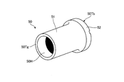
- FIG. 3 is a perspective view of a collar included in the electric motor according to the present embodiment.
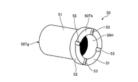
- FIG. 4 is a perspective view of a collar included in the electric motor according to the present embodiment.
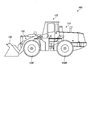
- FIG. 5 is an explanatory view showing a wheel loader.
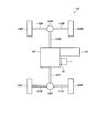
- FIG. 6 is a schematic diagram showing a drive system of the wheel loader.
- FIG. 1 is a cross-sectional view showing an electric motor according to the present embodiment.
- FIG. 2 is an enlarged view of one end side of the shaft of the electric motor according to the present embodiment.
- 3 and 4 are perspective views of a collar included in the electric motor according to the present embodiment.
- the electric motor 1 includes a housing 3, a shaft 10 as a power transmission shaft, a rotor core 20, and a stator 6.
- the housing 3 stores therein the rotor core 20, the shaft 10 to which the rotor core 20 is attached, and the stator 6.
- the housing 3 is a cylindrical structure.
- the housing 3 includes a disk-shaped shaft take-out side member 3T, a cylindrical side portion 3S, and a disk-shaped anti-shaft take-out side member 3R.
- a space surrounded by the shaft take-out side member 3T, the side portion 3S, and the anti-shaft take-out side member 3R is the inside of the housing 3.
- the shaft takeout side member 3T has a through hole 3HA for taking out the shaft 10 to the outside of the housing 3.
- the shaft 10 stored in the housing 3 is taken out from the through hole 3HA.
- the shaft take-out side member 3T and the side portion 3S are manufactured as separate members and are coupled to each other by a fastening member such as a screw.
- both may be integrally formed by casting or the like.
- the non-shaft takeout side member 3R is attached to the end of the side portion 3S on the side opposite to the shaft takeout side member 3T.
- the non-shaft take-out side member 3R is attached to the side portion 3S by a fastening member such as a screw.
- the shaft take-out side member 3 ⁇ / b> T is also a partition wall that separates a lubricating oil that lubricates a reduction gear 60 described later and a cooling medium inside the housing 3.
- An annular stator 6 is attached to the inside of the housing 3, more specifically, to the inner periphery of the side portion 3 ⁇ / b> S.
- the stator 6 is attached over the entire inner periphery of the side portion 3S.
- a rotor core 20 is disposed on the radially inner side of the stator 6.
- the rotor core 20 is a cylindrical structure in which disk-shaped steel plates (magnetic steel plates) 21 are stacked.
- the rotor core 20 has a plurality of permanent magnets embedded therein.
- the electric motor 1 is an IPM (Interior Permanent Magnet), but may be an SPM (Surface Permanent Magnet).
- the rotor core 20 rotates around the rotation center axis Zr.
- the stator 6 is an annular structure having a stator core 6Y and a coil 6C, and the coil 6C is wound around the stator core 6Y. A portion of the coil 6C that protrudes from the stator core 6Y is a coil end 6CE.
- the stator core 6Y is a structure in which a plurality of steel plates (magnetic steel plates) are stacked.
- the electric motor 1 may be an electric motor that does not have a permanent magnet, such as an induction motor.
- the rotor core 20 is a structure in which a plurality of steel plates 21 are attached to the shaft 10 and stacked.
- the direction in which the plurality of steel plates 21 are stacked is an axial direction of the shaft 10, that is, a direction parallel to the rotation center axis Zr.
- Balance plates 30A and 30B are provided at both ends of the rotor core 20 in the stacking direction.
- the balance plates 30 ⁇ / b> A and 30 ⁇ / b> B are annular members and are attached to the outer peripheral portion of the shaft 10.
- the rotor core 20 on which the plurality of steel plates 21 are stacked is sandwiched between two balance plates 30A and 30B.
- the shaft 10 On one balance plate 30A side, the shaft 10 has a rotor core fixing portion 14 having an outer diameter larger than the inner diameter of the balance plate 30A. For this reason, when the balance plate 30 ⁇ / b> A attached to the shaft 10 from the other end 10 ⁇ / b> R side of the shaft 10 contacts the rotor core fixing portion 14, further movement is restricted.
- the rotor core 20 is attached to the shaft 10 by attaching the balance plate 30A, the rotor core 20, and the balance plate 30B to the shaft 10 in this order and screwing the rotor core fixing nut 10NR into the shaft 10.
- the balance plates 30 ⁇ / b> A and 30 ⁇ / b> B give a compressive force to the rotor core 20, that is, the plurality of stacked steel plates 21.
- the diameters of the balance plates 30 ⁇ / b> A and 30 ⁇ / b> B are the same as the diameter of the steel plate 21 or smaller than the diameter of the steel plate 21.
- the shaft 10 is attached to the rotor core 20.
- the shaft 10 extends in the direction of the rotation center axis Zr of the rotor core 20, and a gear 71 can be attached to one end portion 10C side.
- the gear 71 is a bevel gear, but is not limited thereto, and may be a spur gear.
- the shaft 10 is responsible for the output of the electric motor 1 and the input to the electric motor 1.
- the gear 71 of the reduction gear 60 is attached to the one end portion 10 ⁇ / b> C side of the shaft 10.
- the shaft 10 shares the rotor core 20 and the rotation center axis Zr, and rotates around the rotation center axis Zr together with the rotor core 20.
- the shaft 10 outputs the power generated by the electric motor 1 to the outside of the electric motor 1 or inputs the power to the electric motor 1 when the electric motor 1 is used as a generator.
- the gear 71 attached to the shaft 10 also rotates with the shaft 10 about the rotation center axis Zr of the shaft 10.
- the gear 71 is a gear having teeth (oblique teeth) HG inclined with respect to the rotation center axis Zr when viewed from a direction orthogonal to the rotation center axis Zr.
- the electric motor 1 When the electric motor 1 is used for traveling a construction machine such as a wheel loader, it is preferable to reduce the size by rotating at high speed. In such a case, the output of the electric motor 1 is input to the transmission 107 through the reduction gear 60.
- the electric motor 1 rotates at a high speed (for example, 10,000 rotations per minute or more), noise is increased with a spur gear. For this reason, the gear 71 is attached to the shaft 10, and the output of the electric motor 1 is input to the reduction gear 60 to suppress the noise of the reduction gear 60.
- the shaft 10 has bearings 4A and 4B attached to both sides.
- the bearings 4A and 4B are all ball bearings.
- the two bearings 4A and 4B are attached to the housing 3 and support the shaft 10 in a rotatable manner.
- the bearing 4A is attached to the shaft takeout side member 3T
- the bearing 4B is attached to the opposite shaft takeout side member 3R opposite to the shaft takeout side member 3T. That is, the bearing 4A rotatably supports the shaft 10 on the casing 3 on the gear 71 side relative to the rotor core 20, and the bearing 4A supports the shaft 10 on the other end 10R side relative to the rotor core 20 on the casing 3. It is supported rotatably.
- the housing 3 rotatably supports the shaft 10 via the bearings 4A and 4B.
- the bearing 4A is referred to as a first bearing 4A and the bearing 4B is referred to as a second bearing 4B as necessary.
- a spline 10SL is formed on the outer peripheral surface of the shaft 10 on the one end 10C side.
- the shaft 10 has one end portion 10C protruding from the through hole 3HA of the shaft take-out side member 3T.
- the gear 71 is attached to the one end portion 10C side of the shaft 10 as described above.
- a spline coupled to a spline 10SL formed on one end 10 side of the shaft 10 is formed on the inner peripheral surface, and both the splines mesh with each other.
- the power of the electric motor 1 is taken out from the shaft 10 via the gear 71, or the electric power is input to the electric motor 1 to generate electric power from the electric motor 1.
- One end portion 10 ⁇ / b> C side of the shaft 10 is an input / output side of the shaft 10.
- a reduction gear 60 is attached to the housing 3 of the electric motor 1.
- the reduction device 60 is a device that reduces the rotational speed of the shaft 10 of the electric motor 1 and increases the torque and outputs the torque from the output unit.
- the input unit of the reduction gear 60 is a gear 71 attached to the shaft 10 of the electric motor 1.
- the input unit of the reduction gear 60 is a part to which power from a power source such as the electric motor 1 is input.
- the reduction device 60 uses the planetary gear device 70 to reduce the rotational speed of the shaft 10 and output it.
- the reduction gear 60 is not limited to the one using the planetary gear device 70.
- the reduction gear 60 has a planetary gear device 70 stored in a housing 61.
- the casing 61 of the speed reducer 60 is attached to the casing 3 of the electric motor 1, which is the shaft takeout side member 3T in this embodiment.
- the planetary gear device 70 includes a gear 71 as a sun gear, a plurality of pinion gears 72 that mesh with the gear 71, a carrier 73 to which a pinion shaft 72S that rotatably supports the plurality of pinion gears 72 is attached, and a ring gear that meshes with the plurality of pinion gears 72. 74.
- the gear 71 is a spline in which the inner teeth formed on the inner peripheral surface are coupled to the spline SL of the shaft 10, and the outer teeth are inclined teeth.
- the plurality of pinion gears 72 are disposed between the gear 71 and the ring gear 74.
- the carrier 73 is fitted around a rotation center axis Zr with respect to the shaft take-out side member 3T by fitting a pin driven into the shaft take-out side member 3T of the electric motor 1 and a hole provided in the carrier 73. It is attached so as not to rotate.
- the reduction gear 60 the carrier 73 of the planetary gear device 70 is fixed, and the input from the gear 71 as the sun gear is output from the ring gear 74 through the pinion gear 72.
- the ring gear 74 becomes an output part of the reduction gear 60.
- the reduction gear 60 may fix the ring gear 74 and use the carrier 73 as an output unit.
- the ring gear 74 has a connecting member 76 at the end portion farther from the electric motor 1.
- the connecting member 76 is connected to the power transmission shaft 65 of the reduction gear 60.
- the power transmission shaft 65 is rotatably supported by the housing 61 of the speed reduction device 60 via two speed reducer bearings 64A and 64B attached to the power transmission shaft 65.
- the reduction gear bearings 64A and 64B are attached to the power transmission shaft 65 by screwing bearing fixing nuts 65N into the power transmission shaft 65.
- the power transmission shaft 65 is connected to an input unit of a transmission of a construction machine such as a wheel loader, for example.
- the housing 61 of the speed reducer 60 has lubricating oil passages 62 and 63 for supplying lubricating oil (fluid) for lubricating the speed reducer bearings 64A and 64B and the planetary gear device 70.
- the lubricating oil passages 62 and 63 are supplied with lubricating oil from the lubricating oil passages 15 and 16 of the housing 3 of the electric motor 1, in this embodiment, the shaft take-out side member 3T.
- the carrier 73 of the planetary gear device 70 and the pinion shaft 72S attached to the carrier 73 have a lubricating oil passage 75 that receives supply of lubricating oil from the lubricating oil passage 17 of the shaft take-out side member 3T.
- the lubricating oil passage 75 supplies lubricating oil between the pinion gear 72 and the gear 71.
- a cylindrical, more specifically, a cylindrical collar 50 is attached between the outer peripheral portion 10S of the shaft 10 and between the first bearing 4A and the gear 71.
- the collar 50 includes a body portion 51 and a flange portion 52 that is provided at one end of the body portion 51 and projects outward in the radial direction.
- An end portion (flange side end portion) 50Tb on the flange portion 52 side faces the first bearing 4A, and an end portion (anti-flange side end portion) 50Tg on the opposite side to the flange portion 52 faces the gear 71.
- the collar 50 has a through hole 50 ⁇ / b> H penetrating from the flange side end portion 50 ⁇ / b> Tb toward the opposite flange side end portion 50 ⁇ / b> Tg.
- the shaft 10 is fitted into the through hole 50H.
- the collar 50 and the shaft 10 are attached with an interference fit, and both rotate integrally around the rotation center axis Zr.
- the material of the shaft 10 is, for example, chrome molybdenum steel
- the material of the collar 50 is, for example, carbon steel.
- the shaft 10 and the collar 50 are made of different materials. By doing so, a material suitable for the functions of the shaft 10 and the collar 50 can be selected.
- the shaft 10 selects a material suitable for power transmission.
- the collar 50 does not need a power transmission function, but as will be described later, a material suitable for forming a sealing surface for realizing a function of sealing a cooling medium and a lubricating oil as a fluid is selected.
- the first bearing 4A abuts on a bearing locking portion 18 projecting radially outward from the outer peripheral portion 10S of the shaft 10.
- the inner ring 4 i of the first bearing 4 ⁇ / b> A contacts the bearing locking portion 18.
- the flange side end portion 50Tb of the collar 50 attached to the shaft 10 contacts the inner ring 4i of the first bearing 4A.
- the opposite end 50Tg of the collar 50 is in contact with one end 71Ta of a gear 71 attached to one end 10C of the shaft 10.
- a gear retaining ring 10 ⁇ / b> NG is attached to the shaft 10 from the one end portion 10 ⁇ / b> C side of the shaft 10.
- the gear retaining ring 10NG comes into contact with the other end portion 71Tb of the gear 71.
- the gear retaining ring 10NG By attaching the gear retaining ring 10NG to the shaft 10, the first bearing 4A, the collar 50, and the gear 71 are attached to the shaft 10 between the gear retaining ring 10NG and the bearing locking portion 18.
- the gear 71 and the shaft 10 are connected by, for example, a spline, and are positioned between them in the circumferential direction.
- a slight gap is formed between the gear retaining ring 10NG and the gear 71. The clearance allows the movement of the gear 71 in the direction of the rotation center axis Zr.
- the first bearing 4A is attached to the bearing attachment portion 3TB provided with the outer ring 4e on the shaft take-out side member 3T.
- the bearing mounting portion 3TB is a circular hole formed in the shaft take-out side member 3T.
- the inner diameter of the bearing mounting portion 3TB is larger than the inner diameter of the through hole 3HA, and both are connected. For this reason, the step part 19 is formed in the connection part of the bearing attachment part 3TB and the through-hole 3HA.
- the outer ring 4e contacts the step portion 19.
- the bearing attachment member 12 is attached to the shaft take-out side member 3T in a state where the first bearing 4A is attached to the bearing attachment portion 3TB.
- the bearing attachment member 12 is attached to the shaft take-out side member 3T with a bolt 13 as a fastening means.
- the shaft 10 penetrates through the through hole 12H, and the bearing mounting member 12 is mounted from the rotor core 20 side to the inside of the housing 3, in this embodiment, to the inside of the shaft take-out side member 3T.
- the inner diameter of the through hole 12H is smaller than the outer diameter of the outer ring 4e of the first bearing 4A and larger than the inner diameter of the outer ring 4e.
- the bearing mounting member 12 faces only the outer ring 4e of the first bearing 4A. Therefore, even if the bearing mounting member 12 is mounted on the shaft take-out side member 3T, the bearing mounting member 12 does not interfere with the inner ring 4i and the rolling element 4b, so the bearing mounting member 12 does not hinder these movements.
- the first bearing 4 ⁇ / b> A is attached to the shaft take-out side member 3 ⁇ / b> T by the bearing attachment member 12.
- the bearing mounting member 12 is provided so as to protrude from the shaft take-out side member 3T to the outer ring 4e side (the shaft 10 side with respect to the stator 6) of the first bearing 4A.
- the bearing mounting member 12 is mounted such that the surface on the shaft take-out side member 3T side is flush with the end surface of the outer ring 4e. By doing so, the movement of the first bearing 4A is regulated.
- the opposite side of the first bearing 4A is positioned so that the first bearing 4A does not move by press-fitting the collar 50 into the shaft 10.
- the collar 50 has a groove 53 as a passage extending from the inner peripheral portion of the collar 50 toward the outer peripheral portion.
- the collar 50 has a groove 53 at a portion facing the first bearing 4 ⁇ / b> A, that is, the flange side end portion 50 ⁇ / b> Tb of the flange portion 52.
- the location where the groove 53 is provided is not limited to this portion.
- the inner diameter side of the collar 50 opens into a cooling medium supply groove 10 p provided toward the circumferential direction of the outer peripheral portion 10 ⁇ / b> S of the shaft 10.
- the opening of the groove 53 on the outer peripheral side of the collar 50 is connected between the first bearing 4A and the sealing member 5A.
- the cooling medium is supplied from the cooling medium supply passage 11 of the shaft 10 to the cooling medium supply groove 10p.
- the groove 53 rotates together with the shaft 10 and the collar 50 and discharges the cooling medium supplied from the cooling medium supply groove 10p to the outer side in the radial direction of the collar 50, thereby supplying the cooling medium to the first bearing 4A.
- the cooling medium cools the coil 6C and the rotor core 20 of the stator 6 of the electric motor 1 and lubricates the sliding portion.
- a through hole penetrating the collar 50 from the inner peripheral portion of the collar 50 toward the outer peripheral portion may be used as a passage extending from the inner peripheral portion of the collar 50 toward the outer peripheral portion.
- a sealing member 5A is provided on the outer peripheral portion of the collar 50 attached to the shaft 10.
- a sealing member 5A is provided between the collar 50 and the housing 3, more specifically between the shaft take-out side member 3T.
- the sealing member 5 ⁇ / b> A only needs to be provided on the outer peripheral portion of the collar 50, and may be provided at a location other than between the collar 50 and the housing 3.
- the sealing member 5 ⁇ / b> A may be provided between the collar 50 and the casing 61 of the speed reduction device 60.
- a sealing member 5B is provided between the shaft 10 and the housing 3 on the other end 10R side, and the anti-shaft take-out side member 3R in this embodiment.
- the sealing members 5A and 5B are oil seals.
- An oil seal 5C as a sealing member is provided between the second bearing 4B and the sealing member 5B.
- a rotation speed sensor 5I that detects the rotation speed of the shaft 10 is provided between the shaft 10 and the housing 3, in this embodiment, the anti-shaft takeout side member 3R. The rotation speed sensor 5I is disposed between the second bearing 4B and the sealing member 5B.
- the sealing member 5 ⁇ / b> A is a through hole 3 ⁇ / b> HA of the shaft take-out side member 3 ⁇ / b> T, and is attached between the first bearing 4 ⁇ / b> A and one end 10 ⁇ / b> C of the shaft 10, more specifically, at a position facing the collar 50. .
- the sealing member 5B is disposed on the other end 10R side of the shaft 10 relative to the second bearing 4B, and is attached to the through hole 3HB of the anti-shaft takeout side member 3R.
- the electric motor 1 is cooled by the cooling medium (for example, oil) and the bearings 4A and 4B are lubricated, so that the cooling medium leaking from the shaft 10 to the outside of the housing 3 is suppressed.
- Sealing members 5 ⁇ / b> A and 5 ⁇ / b> B are provided between the housing 3 and the shaft 10.
- the lubricating oil for lubricating the reduction gear 60 is supplied to the electric motor 1 via the first bearing 4A adjacent to the reduction gear 60. There is a possibility of entering the inside (inside the housing 3). Since the lubricating oil of the reduction gear 60 includes the abrasion powder of the planetary gear device 70, if it enters the electric motor 1, the durability of the first bearing 4A, the rotor core 20 and the stator 6 may be reduced. .
- the speed reduction device 60 when the speed reduction device 60 is applied to a construction machine such as a wheel loader, the operation at a continuous high load is more than that applied to an automobile, and the temperature of the oil on the speed reduction device side constitutes the electric motor 1. There is a possibility that the temperature will be higher than the heat resistance temperature of the parts, and the amount of abrasion powder generated will increase.
- the sealing member 5 ⁇ / b> A provided in the portion of the collar 50 between the electric motor 1 and the reduction gear 60 reduces the possibility that the lubricating oil of the reduction gear 60 will enter the electric motor 1.
- the sealing member 5 ⁇ / b> A can suppress the flow of the lubricating oil and the cooling medium as fluid between the housing 3 and the outside of the housing 3.
- the sealing member 5A contains a large amount of wear powder and reduces the possibility that the lubricating oil of the reduction gear 60 that has become hot enters the inside of the electric motor 1 to operate the electric motor 1 stably. 1 can be suppressed.
- two sealing members 5A are provided in the direction of the rotation center axis Zr.
- 5 A of sealing members can suppress more effectively the possibility that the lubricating oil of the reduction gear 60 may enter the inside of the electric motor 1.
- the space (sealing member space) between the two sealing members 5 ⁇ / b> A is connected to the gas reservoir 16.
- the gas reservoir 16 is provided in the shaft take-out side member 3T in this embodiment, but the gas reservoir 16 may be provided in a portion other than this.
- the gas reservoir 16 is a portion that holds a certain amount of gas (air), and may be open to the atmosphere.
- the shaft 10 has a gear 71 attached to one end portion 10C side.
- the shaft 10 transmits power from the gear 71 to the reduction gear 60 and transmits power from the reduction gear 60 to the electric motor 1 via the gear 71.
- a wheel loader or the like on which the reduction gear 60 and the electric motor 1 are mounted travels or works, vibrations are generated. Due to this vibration, a thrust force is generated on the shaft 10 of the electric motor 1.
- the gear 71 is an inclined gear
- the gear 71 rotates, a thrust force resulting from the rotation of the inclined gear is generated in addition to the thrust force resulting from the vibration described above.
- the above-described thrust force moves the first bearing 4A or the second bearing 4B through the shaft 10 in the direction of the rotation center axis Zr, and accordingly, moves the rotor core 20 in the direction of the rotation center axis Zr. is there. For this reason, backlash may occur between the first bearing 4 ⁇ / b> A or the second bearing 4 ⁇ / b> B and the shaft 10.
- a collar 50 is interposed between the gear 71 and the first bearing 4 ⁇ / b> A, and the thrust force is transmitted between the first bearing 4 ⁇ / b> A and the gear 71 via the collar 50.
- the first bearing 4A is attached to the shaft take-out side member 3T from the rotor core 20 side by the bearing attachment member 12.
- the thrust force from the gear 71 toward the first bearing 4A is transmitted in the order of the collar 50, the first bearing 4A, and the bearing mounting member 12, and the shaft take-out side member 3T to which the bearing mounting member 12 is mounted. Receive. Further, the thrust force directed from the second bearing 4B to the first bearing 4A is transmitted in the order of the shaft 10, the first bearing 4A, and the step portion 19 and is received by the shaft take-out side member 3T in which the step portion 19 is formed. Since the thrust force in any direction is received by the shaft take-out side member 3T that constitutes the housing 3 of the electric motor 1, the displacement of the first bearing 4A and the second bearing 4B in the rotation center axis Zr direction due to the thrust force is suppressed. it can. As a result, backlash can be reduced between the first bearing 4A or the second bearing 4B and the shaft 10.
- the rotation direction of the electric motor 1 is also frequently switched.
- the rotation direction of the gear 71 is also frequently switched, when the gear 71 is a bevel gear, the direction of the thrust force acting on the shaft 10 is also frequently switched.
- the gear 71 moves in the direction of the rotation center axis Zr by the amount of play in the direction of the rotation center axis Zr, so that an impact force acts on the shaft 10 as a thrust force.
- the shaft take-out side member 3T constituting the housing 3 of the electric motor 1 receives the thrust force from the gear 71 by the above-described structure, and therefore, even when an impact force acts as the thrust force, the shaft take-out side member 3T. Can reliably receive the impact force and minimize the load on the bearings 4A and 4B.
- the electric motor 1 is particularly preferable for applications in which the rotation direction is frequently switched, such as a turning motor that drives a traveling motor of a wheel loader and an upper turning body of a hydraulic excavator.
- the gear 71, the collar 50, and the first bearing 4A are fixed to the shaft 10 by one gear retaining ring 10NG.
- a nut for fixing the first bearing 4A to the shaft 10 is required in addition to the gear retaining ring 10NG. Since this nut increases the dimension of the shaft 10 in the direction of the rotation center axis Zr, in addition to an increase in the dimension of the electric motor 1 in the direction of the rotation center axis Zr, the bending rigidity of the shaft 10 may be reduced. Furthermore, it is necessary to make the diameter of the shaft 10 larger in the portion where the nut is screwed into the shaft 10 than in the portion where the gear 71 is attached.
- the collar 50 is not used, a nut is required in addition to the gear retaining ring 10NG, and the diameter of the shaft 10 increases.
- the moment of inertia of the shaft 10 increases due to an increase in the diameter of the shaft 10 and an additional nut.
- the gear 71, the collar 50, and the first bearing 4A can be fixed to the shaft 10 by one gear retaining ring 10NG.
- the collar 50 when the collar 50 is not used, it is conceivable that a portion of the gear 71 where the inclined teeth are not formed is extended in the direction of the first bearing 4A and a portion corresponding to the collar 50 is provided in the gear 71.
- the collar 50 in order to attach a gear to the shaft 10, it is necessary to extend the spline to the vicinity of the first bearing 4A. Then, since the spline is formed on the shaft 10 beyond the sealing member 5A, there is a possibility that the lubricating oil of the reduction gear 60 moves to the first bearing 4A through the spline.
- the collar 50 is attached to the shaft 10 by a tight fit, and the sealing member 5A is disposed between the collar 50 and the shaft take-out side member 3T. For this reason, it is possible to avoid the lubricating oil of the reduction gear 60 from passing between the collar 50 and the shaft 10.
- the gear 71, the collar 50, and the first bearing 4A can be fixed to the shaft 10 with one gear retaining ring 10NG, and therefore the shaft 10 in the direction of the rotation center axis Zr.
- the increase in dimension can be suppressed. For this reason, since the fall of the bending rigidity of the shaft 10 is suppressed, the shake of the shaft 10 resulting from the vibration generated when the gear 71 rotates is also reduced. As a result, the sealing state between the sealing member 5A and the shaft 10 can be reliably maintained. This is particularly advantageous when the shaft 10 rotates at a high speed.
- the cooling structure 2 of the electric motor 1 will be described.
- the shaft 10 has a cooling medium supply passage 11 for passing a cooling medium for cooling the electric motor 1 from the inside.
- the cooling medium supply passage 11 is provided along the rotation center axis Zr.
- the cooling medium supply passage 11 is preferably provided on the rotation center axis Zr.
- the shaft 10 may be a hollow shaft, and another shaft may be passed through the shaft 10. In this case, a space formed between the shaft 10 and another shaft penetrating the shaft 10 can be used as the cooling medium supply passage 11.
- the cooling medium supply passage 11 is inside the shaft 10 and extends from the other end 10R in the axial direction of the shaft 10, that is, in the direction of the rotation center axis Zr.
- the other end portion 10 ⁇ / b> R of the shaft 10 is provided with a cooling medium inlet 11 ⁇ / b> I through which the cooling medium flows into the cooling medium supply passage 11.
- the other end 10R side of the shaft 10 is the cooling medium inlet side.
- a plurality of cooling medium passages 40A and 40B are branched from the cooling medium supply passage 11. 1 shows a cross section when the shaft 10 is cut along a plane parallel to the rotation center axis Zr of the shaft 10 and including the rotation center axis Zr. However, for convenience of explanation, a plurality of cooling medium passages 40A are formed in the same section. , 40B appears. However, in actuality, the cooling medium passages 40A and 40B appear in the respective cross sections when the shaft 10 is cut by planes whose central angles about the rotation center axis Zr are different by 90 degrees.
- the plurality of cooling medium passages 40A and 40B are branched from the cooling medium supply passage 11, and after cooling the rotor core 20 while flowing in one direction without branching the cooling medium in the axial direction of the shaft 10, the rotor core
- the cooling medium is discharged from the discharge ports 40AH and 40BH opened on the surface of 20.
- the plurality of cooling medium passages 40A and 40B have the same distance (passage distance) from the cooling medium inlet 11I through which the cooling medium flows into the cooling medium supply passage 11 to the discharge ports 40AH and 40BH.
- the cooling medium discharged from the discharge ports 40AH and 40BH flows out from the cooling medium outlets 31B and 31A of the balance plates 30B and 30A into the housing 3.
- the cooling medium that has flowed out of the cooling medium outlets 31 ⁇ / b> B and 31 ⁇ / b> A due to the centrifugal force caused by the rotation is blown outward in the radial direction of the rotor core 20. Then, the cooling medium blown outward in the radial direction cools the coil end 6CE.
- a cooling medium recovery passage 7 ⁇ / b> B is provided on the side 3 ⁇ / b> S of the housing 3.
- the cooling medium recovery passage 7B is provided below (on the direction side where gravity acts, and in the direction indicated by arrow G in FIG. 1) when the electric motor 1 is used.
- the state in which the wheel loader is in contact with the horizontal plane is the state in which the electric motor 1 is used, and the cooling medium recovery passage 7B is provided at a lower position in that state. It is done.
- the housing 3 has a coil end cooling passage 7T at a portion facing the coil end 6CE and avoiding the cooling medium recovery passage 7B.
- a cooling medium is also supplied to the coil end 6CE from the coil end cooling passage 7T to cool the coil end 6CE.
- the coil end cooling passage 7T is not necessarily provided. For example, whether or not the coil end cooling passage 7T is provided in the housing 3 in accordance with the specifications of the electric motor 1 or the mounting target of the electric motor 1 or the operating conditions. It is determined.
- the coil end cooling passage 7T is disposed above (on the opposite side to the vertical direction) when the electric motor is disposed such that the rotation center axis Zr of the shaft 10 is orthogonal to the vertical direction (direction of gravity action). Is preferable, and more preferably, it is arranged at the uppermost position (that is, at the top position).
- the cooling medium is supplied to the electric motor 1 by the pump 8 which is a cooling medium circulating means, and is sucked by the pump 8 after the electric motor 1 is cooled.
- the suction port of the pump 8 is connected to the cooling medium recovery passage 7B by the first cooling medium pipe CL1.
- the discharge port of the pump 8 is connected to the electric motor 1 by the second cooling medium pipe CL2.
- the second cooling medium pipe CL2 branches into a shaft side supply pipe CLA and a coil end side supply pipe CLB.
- the former is connected to the cooling medium inlet 11I of the cooling medium supply passage 11, and the latter is connected to the coil end cooling passage 7T, and supplies the cooling medium discharged from the pump 8 to each connection target.
- the cooling structure 2 includes a cooling medium supply passage 11 and a plurality of cooling medium passages 40A and 40B.
- a part of the cooling medium discharged from the pump 8 flows through the second cooling medium pipe CL2 and flows into the shaft side supply pipe CLA and the rest flows through the coil end side supply pipe CLB.
- the coolant that has flowed into the shaft-side supply pipe CLA passes through the coolant inlet 11I and then partially flows into the coolant passages 40A and 40B.
- the cooling medium cools the rotor core 20 in the process of passing through the cooling medium passages 40A and 40B, and is discharged into the housing 3 from the discharge ports 40AH and 40BH.
- the cooling medium discharged into the housing 3 reaches the coil end 6CE by the centrifugal force of the rotor core 20, and cools it.
- the cooling medium that has flowed into the coil end side supply pipe CLB flows into the coil end cooling passage 7T, and then is supplied to the coil end 6CE to cool it.
- the coil end 6CE is cooled by the coil end cooling passage 7T even when the motor 1 is operated under operating conditions in which the cooling of the coil end 6CE by the cooling medium flowing out from the cooling medium outlets 31B and 31A tends to be insufficient. be able to. For this reason, the coil end cooling passage 7T can stably operate the electric motor 1 even under various operating conditions.
- the cooling medium that has cooled the coil end 6CE and the cooling medium that has cooled and lubricated the bearings 4A and 4B flow below the housing 3 due to the action of gravity.
- This cooling medium is discharged to the outside of the housing 3 through the cooling medium recovery passage 7B.
- the cooling medium discharged to the outside of the housing 3 is sucked into the pump 8 through the first cooling medium pipe CL1.
- the pump 8 discharges the sucked cooling medium to the second cooling medium pipe CL2.
- the pump 8 is used to connect the electric motor 1 between the first cooling medium pipe CL1, the second cooling medium pipe CL2, the shaft side supply pipe CLA, and the coil end side supply pipe CLB. Circulate the cooling medium.
- the cooling structure 2 repeats the cooling of the rotor core 20 and the coil end 6CE and the lubrication and cooling of the bearings 4A and 4B.
- the first cooling medium pipe CL1 and the second cooling medium pipe CL2 are cooled with a filter that removes foreign matters in the cooling medium, and the first cooling medium pipe CL1, and the rotor core 20 and the coil end 6CE are cooled. You may provide the cooler which cools the cooling medium which raised temperature.
- the means for supplying the cooling medium to the coil end cooling passage 7T is provided with a cooling medium supply pump different from the pump 8 in addition to the cooling medium circulation structure as described above.
- a circulation structure that supplies a cooling medium to the passage 7T may be used. That is, the electric motor 1 may have a cooling circuit dedicated to the coil end cooling passage 7T.
- the cooling structure 2 can be applied regardless of whether or not the electric motor 1 has a magnet.
- a wheel loader that is a type of construction vehicle will be described as an example of a work vehicle to which the electric motor according to the present embodiment is applied.
- the application target of the electric motor of the present embodiment is not limited to a construction vehicle, and is not limited to a wheel loader in a construction vehicle.
- FIG. 5 is an explanatory view showing a wheel loader.
- the wheel loader 100 supports the vehicle body 101, a lift arm (work machine) 102 attached to the front of the vehicle body 101, a bucket (work machine) 103 attached to the tip of the lift arm 102, and the vehicle body 101.
- Two front wheels 104 ⁇ / b> F and two rear wheels 104 ⁇ / b> R for rotating the vehicle body 101 and a cab 105 mounted on the upper portion of the vehicle body 101 are provided.
- FIG. 6 is a schematic diagram showing a drive system of the wheel loader.
- the wheel loader 100 includes an internal combustion engine 106 such as a diesel engine or a gasoline engine and the electric motor 1 as a power generation source.
- the drive system of the wheel loader 100 is a so-called hybrid system.
- the wheel loader 100 includes one electric motor 1, but the number of the electric motors 1 is not limited to this.
- the output of the internal combustion engine 106 is input to the transmission 107.
- the output of the electric motor 1 is input to the transmission device 107 via the speed reduction device 60.
- the transmission 107 combines the outputs of the internal combustion engine 106 and the electric motor 1 and then outputs them to the front wheel side propeller shaft 108F and the rear wheel side propeller shaft 108R.
- the output of the front wheel side propeller shaft 108F is transmitted to the two front wheels 104F via the front wheel side differential gear 109F and the front wheel side drive shaft 110F.
- the output of the rear wheel side propeller shaft 108R is transmitted to the two rear wheels 104R via the rear wheel side differential gear 109R and the rear wheel side drive shaft 110R.
- the outputs of the internal combustion engine 106 and the electric motor 1 are transmitted to the front wheels 104F and the rear wheels 104R to cause the wheel loader 100 to travel.
- the wheel loader 100 includes an inverter that controls the operation (power running or regeneration) of the electric motor 1 and a power storage device such as a capacitor or a secondary battery that stores energy (electric power) obtained by the regeneration of the electric motor 1. Yes.
- the wheel loader 100 may be an electric vehicle (work vehicle or construction vehicle) that does not have an internal combustion engine and uses the electric motor 1 as a drive source by the electric power of the power storage device. That is, the electric motor 1 according to the present embodiment can be applied regardless of a hybrid vehicle or an electric vehicle.
- the electric motor 1 and the internal combustion engine 106 are placed horizontally. That is, the power transmission shafts of the electric motor 1 and the internal combustion engine 106 are orthogonal to the traveling direction when the wheel loader 100 is traveling straight, more specifically, orthogonal to the front wheel side propeller shaft 108F and the rear wheel side propeller shaft 108R.
- the electric motor 1 and the internal combustion engine 106 are arranged.
- the arrangement of the electric motor 1 and the internal combustion engine 106 is not limited to the horizontal position, but the vertical position, that is, the power transmission shaft of the electric motor 1 and the internal combustion engine 106 is the same as that of the front wheel side propeller shaft 108F and the rear wheel side propeller shaft 108R. You may arrange
- the electric motor according to the present embodiment includes a shaft to which a gear can be attached on one end side, a bearing that rotatably supports the shaft on the housing on the gear side of the rotor core, an outer peripheral portion of the shaft, and A cylindrical collar attached between the bearing and the gear, and a bearing attachment member attached to the inside of the casing from the rotor core side and attaching the bearing to the casing.
- the electric motor according to the present embodiment can reduce the influence of the thrust force generated by the rotation of the gears on the electric motor.
- the structure as described above can suppress a decrease in the bending rigidity of the shaft, and the lubricating oil can be prevented from passing between the collar and the shaft. The possibility of entering can be reduced.
- the electric motor according to the present embodiment is used in applications where it is desired to avoid the lubricating oil from entering the electric motor, for example, applications in which the electric motor and the speed reducer are disposed adjacent to each other (for example, for running a construction machine such as a wheel loader). Etc.).
Landscapes
- Engineering & Computer Science (AREA)
- General Engineering & Computer Science (AREA)
- Mechanical Engineering (AREA)
- Power Engineering (AREA)
- Life Sciences & Earth Sciences (AREA)
- Sustainable Development (AREA)
- Sustainable Energy (AREA)
- Transportation (AREA)
- Connection Of Motors, Electrical Generators, Mechanical Devices, And The Like (AREA)
- Gears, Cams (AREA)
- General Details Of Gearings (AREA)
- Mounting Of Bearings Or Others (AREA)
- Sealing Of Bearings (AREA)
- Rolling Contact Bearings (AREA)
- Motor Or Generator Frames (AREA)
Description
図1は、本実施形態に係る電動機を示す断面図である。図2は、本実施形態に係る電動機が有するシャフトの一方の端部側の拡大図である。図3、図4は、本実施形態に係る電動機が有するカラーの斜視図である。電動機1は、筐体3と、動力伝達軸としてのシャフト10と、ローターコア20と、ステーター6とを含んでいる。筐体3は、ローターコア20、ローターコア20が取り付けられたシャフト10及びステーター6を内部に格納する。筐体3は、筒状の構造体である。本実施形態において、筐体3は、円板形状のシャフト取り出し側部材3Tと、円筒形状の側部3Sと、円板形状の反シャフト取り出し側部材3Rとを有する。シャフト取り出し側部材3Tと、側部3Sと、反シャフト取り出し側部材3Rとで囲まれる空間が、筐体3の内部になる。
電動機1は、筐体3の内部が冷却媒体で冷却される。このため、図1に示すように、シャフト10は、電動機1を内部から冷却するための冷却媒体を通過させるための冷却媒体供給通路11を有している。本実施形態において、冷却媒体供給通路11は、回転中心軸Zrに沿って設けられる。冷却媒体供給通路11は、回転中心軸Zr上に設けられていることが好ましい。また、シャフト10を中空シャフトとし、シャフト10内にさらに別のシャフトを貫通させるような構造であってもよい。この場合、シャフト10と、シャフト10内を貫通する別のシャフトとの間に形成される空間を、冷却媒体供給通路11とすることができる。冷却媒体供給通路11は、シャフト10の内部であって、他方の端部10Rからシャフト10の軸方向、すなわち、回転中心軸Zr方向に向かって延在している。このため、シャフト10の他方の端部10Rには、冷却媒体が冷却媒体供給通路11へ流入する冷却媒体入口11Iが設けられる。このように、シャフト10の他方の端部10R側は、冷却媒体入口側になる。
図5は、ホイールローダを示す説明図である。ホイールローダ100は、車体101と、車体101の前部に装着されたリフトアーム(作業機)102と、リフトアーム102の先端に取り付けられたバケット(作業機)103と、車体101を支持しながら回転して車体101を走行させる2本の前輪104F及び2本の後輪104Rと、車体101の上部に搭載されたキャブ105と、を備えている。
2 冷却構造
3 筐体
3R 反シャフト取り出し側部材
3S 側部
3T シャフト取り出し側部材
3TB 軸受取付部
4A 第1軸受(軸受)
4B 第2軸受(軸受)
4b 転動体
4e 外輪
4i 内輪
5A、5B 封止部材
6 ステーター
10 シャフト
10C 一方の端部
10NG 歯車止め輪
10NR ローターコア固定ナット
10R 他方の端部
10S 外周部
10p 冷却媒体供給溝
11 冷却媒体供給通路
12 軸受取付部材
14 ローターコア固定部
15、17 潤滑油通路
18 軸受係止部
19 段部
20 ローターコア
50 カラー
53 溝
60 減速装置
61 筐体
65 動力伝達シャフト
70 遊星歯車装置
71 歯車
72 ピニオンギヤ
73 キャリア
74 リングギヤ
100 ホイールローダ
Claims (10)
- 筒状の筐体の内側に取り付けられた環状のステーター及び前記ステーターの径方向内側に配置されたローターコアを有する電動機であって、
前記ローターコアに取り付けられて前記ローターコアの回転中心軸の方向に延在し、かつ一方の端部側に歯車が取付け可能なシャフトと、
前記ローターコアよりも前記歯車側で前記シャフトを前記筐体に回転可能に支持する軸受と、
前記シャフトの外周部、かつ前記軸受と前記歯車との間に取り付けられる筒状のカラーと、
前記ローターコア側から前記筐体の内側に取り付けられて、前記軸受を前記筐体に取り付ける軸受取付部材と、
を含むことを特徴とする電動機。 - 前記カラーの外周部には封止部材が設けられる、請求項1に記載の電動機。
- 前記カラーは、前記カラーの内周部から外周部に向かって延在する通路を有する、請求項1又は2に記載の電動機。
- 前記カラーの外周部には封止部材が設けられ、また、前記カラーは、前記カラーの内周部から外周部に向かって延在する通路を有し、
前記外周部側における前記通路の開口部は、前記軸受と前記封止部材との間につながっている、請求項1に記載の電動機。 - 前記封止部材は、前記回転中心軸の方向に向かって2個設けられる、請求項2に記載の電動機。
- 2個の前記封止部材の間の空間は、気体溜めに接続している、請求項5に記載の電動機。
- 前記筐体には減速装置が取り付けられており、前記歯車は前記減速装置の入力部である、請求項1から5のいずれか1項に記載の電動機。
- 前記減速装置は遊星歯車装置を有しており、前記歯車は、前記遊星歯車装置のサンギヤである、請求項6に記載の電動機。
- 筒状の筐体の内側に取り付けられた環状のステーター及び前記ステーターの径方向内側に配置されたローターコアとを有する電動機であって、
前記ローターコアに取り付けられて前記ローターコアの回転中心軸の方向に延在し、かつ一方の端部側に歯車が取付け可能なシャフトと、
前記ローターコアよりも前記歯車側で前記シャフトを前記筐体に回転可能に支持する軸受と、
前記シャフトの外周部、かつ前記軸受と前記歯車との間に取り付けられて、内周部から外周部に向かって延在する通路を有する筒状のカラーと、
前記ローターコア側から前記筐体の内側に取り付けられて、前記軸受を前記筐体に取り付ける軸受取付部材と、
前記カラーと前記筐体との間に設けられて、前記筐体と前記筐体の外部との間における流体の流れを抑制する封止部材と、を含み、
前記カラーの外周部側における前記通路の開口部は、前記軸受と前記封止部材との間につながっていることを特徴とする電動機。 - 前記筐体の内部は、冷却媒体により冷却される、請求項1から9のいずれか1項に記載の電動機。
Priority Applications (4)
| Application Number | Priority Date | Filing Date | Title |
|---|---|---|---|
| CN201280060014.1A CN103975510B (zh) | 2012-03-14 | 2012-11-14 | 电动机 |
| US14/366,069 US20140364263A1 (en) | 2012-03-14 | 2012-11-14 | Motor |
| DE112012006023.7T DE112012006023T5 (de) | 2012-03-14 | 2012-11-14 | Motor |
| KR1020147014905A KR101591214B1 (ko) | 2012-03-14 | 2012-11-14 | 전동기 |
Applications Claiming Priority (2)
| Application Number | Priority Date | Filing Date | Title |
|---|---|---|---|
| JP2012-056650 | 2012-03-14 | ||
| JP2012056650A JP5956203B2 (ja) | 2012-03-14 | 2012-03-14 | 電動機 |
Publications (1)
| Publication Number | Publication Date |
|---|---|
| WO2013136589A1 true WO2013136589A1 (ja) | 2013-09-19 |
Family
ID=49160542
Family Applications (1)
| Application Number | Title | Priority Date | Filing Date |
|---|---|---|---|
| PCT/JP2012/079553 Ceased WO2013136589A1 (ja) | 2012-03-14 | 2012-11-14 | 電動機 |
Country Status (6)
| Country | Link |
|---|---|
| US (1) | US20140364263A1 (ja) |
| JP (1) | JP5956203B2 (ja) |
| KR (1) | KR101591214B1 (ja) |
| CN (1) | CN103975510B (ja) |
| DE (1) | DE112012006023T5 (ja) |
| WO (1) | WO2013136589A1 (ja) |
Cited By (3)
| Publication number | Priority date | Publication date | Assignee | Title |
|---|---|---|---|---|
| JP2022018909A (ja) * | 2020-07-16 | 2022-01-27 | トヨタ自動車株式会社 | 駆動装置のシール構造 |
| US11274740B2 (en) * | 2016-09-29 | 2022-03-15 | Borgwarner Sweden Ab | Lubrication system for an axle drive |
| CN117203452A (zh) * | 2021-05-10 | 2023-12-08 | 株式会社小松制作所 | 电动缸以及作业机械 |
Families Citing this family (25)
| Publication number | Priority date | Publication date | Assignee | Title |
|---|---|---|---|---|
| JP2012122552A (ja) * | 2010-12-09 | 2012-06-28 | Kobelco Contstruction Machinery Ltd | 建設機械の駆動装置 |
| CN105848951B (zh) * | 2014-01-08 | 2019-04-19 | Ntn株式会社 | 轮内电动机驱动装置 |
| JP6140104B2 (ja) * | 2014-05-22 | 2017-05-31 | ファナック株式会社 | エアパージ機能を有する電動機 |
| KR101703614B1 (ko) * | 2015-09-10 | 2017-02-07 | 현대자동차 주식회사 | 구동모터와 감속기의 연결 구조 |
| FR3056843B1 (fr) * | 2016-09-28 | 2019-11-15 | Valeo Equipements Electriques Moteur | Machine electrique tournante a configuration de montage d'arbre amelioree |
| JP6981006B2 (ja) * | 2017-02-03 | 2021-12-15 | 日本電産株式会社 | モータ |
| JP6437033B2 (ja) * | 2017-03-28 | 2018-12-12 | 本田技研工業株式会社 | 動力伝達装置 |
| US10801606B2 (en) * | 2017-06-30 | 2020-10-13 | Tesla, Inc. | Electric drive unit with gear shaft and rotor shaft |
| CN207265810U (zh) * | 2017-09-05 | 2018-04-20 | 东风德纳车桥有限公司 | 一种集成主动齿轮电机总成 |
| JP6919989B2 (ja) * | 2017-09-08 | 2021-08-18 | トヨタ自動車株式会社 | 車両用回転電機の冷却装置 |
| CN109728678A (zh) * | 2017-10-30 | 2019-05-07 | 比亚迪股份有限公司 | 电动总成及具有其的转向架和单轨列车 |
| JP7025945B2 (ja) * | 2018-01-31 | 2022-02-25 | 株式会社小松製作所 | 電動機、回転駆動システム及び油圧ショベル |
| DE102018107408B4 (de) * | 2018-03-28 | 2022-10-27 | Schunk Carbon Technology Gmbh | Ableitvorrichtung zur Ableitung elektrischer Ströme |
| KR102135380B1 (ko) * | 2019-06-11 | 2020-07-17 | 엘지전자 주식회사 | 모터 |
| CN110733334B (zh) * | 2019-10-29 | 2022-07-12 | 宁波菲仕运动控制技术有限公司 | 一种电驱动总成的电机转子冷却系统 |
| US11811296B2 (en) | 2020-02-12 | 2023-11-07 | Deere & Company | Electric machine with configurable stator/rotor cooling |
| US11780319B2 (en) * | 2020-04-07 | 2023-10-10 | Deere & Company | Work vehicle electric drive assembly cooling arrangement |
| DE102020116762A1 (de) | 2020-05-06 | 2021-11-11 | Liebherr-Components Biberach Gmbh | Antriebseinheit für eine Bau- und/oder Materialumschlagsmaschine |
| US11787275B2 (en) | 2020-06-10 | 2023-10-17 | Deere & Company | Electric drive with hydraulic mounting interface |
| CN112160991B (zh) * | 2020-08-27 | 2021-12-07 | 东风汽车集团有限公司 | 油浴式发动机联轴装置及发动机试验装置 |
| DE102020132468A1 (de) * | 2020-12-07 | 2022-06-09 | Schaeffler Technologies AG & Co. KG | Axiale Fixierung einer Wellenkomponente einer elektrischen Maschine |
| US12276083B2 (en) * | 2021-03-31 | 2025-04-15 | Nabtesco Corporation | Speed reducer and construction machine |
| CN113890261B (zh) * | 2021-10-27 | 2022-12-23 | 苏州汇川控制技术有限公司 | 直驱机构和加工设备 |
| JP2023067110A (ja) * | 2021-10-29 | 2023-05-16 | ニデック株式会社 | 駆動装置 |
| CN113847414A (zh) * | 2021-11-08 | 2021-12-28 | 黄秀芳 | 一种往复泵电机轴辅助支撑滑动轴承和齿轮润滑结构 |
Citations (4)
| Publication number | Priority date | Publication date | Assignee | Title |
|---|---|---|---|---|
| JPS62147170A (ja) * | 1985-12-19 | 1987-07-01 | Hitachi Ltd | ギヤモ−トルにおけるオイルシ−ルの機能維持構造 |
| JPH04185262A (ja) * | 1990-11-20 | 1992-07-02 | Aisin Aw Co Ltd | ホイールモータの潤滑装置 |
| JPH1026218A (ja) * | 1997-03-31 | 1998-01-27 | Hitachi Ltd | ギヤモートル |
| JP2007154998A (ja) * | 2005-12-05 | 2007-06-21 | Oriental Motor Co Ltd | 歯車減速機付電動機のグリース漏れ防止構造 |
Family Cites Families (7)
| Publication number | Priority date | Publication date | Assignee | Title |
|---|---|---|---|---|
| US2173339A (en) * | 1935-01-07 | 1939-09-19 | Us Electrical Motors Inc | Geared power unit |
| US4260918A (en) * | 1978-12-18 | 1981-04-07 | Reliance Electric Company | Explosion proof submersible gearmotor |
| JPS6077848U (ja) * | 1983-11-01 | 1985-05-30 | 三菱電機株式会社 | 変速装置 |
| JP2734460B2 (ja) * | 1992-07-07 | 1998-03-30 | 三菱電機株式会社 | 電気自動車用駆動電動機 |
| JP2005110482A (ja) * | 2003-12-11 | 2005-04-21 | Igarashi Denki Seisakusho:Kk | モータの軸受構造 |
| JP2005168145A (ja) * | 2003-12-01 | 2005-06-23 | Nikon Corp | モータユニット及びカメラ |
| JP4485566B2 (ja) * | 2007-11-13 | 2010-06-23 | 本田技研工業株式会社 | モータ式動力装置 |
-
2012
- 2012-03-14 JP JP2012056650A patent/JP5956203B2/ja not_active Expired - Fee Related
- 2012-11-14 CN CN201280060014.1A patent/CN103975510B/zh not_active Expired - Fee Related
- 2012-11-14 DE DE112012006023.7T patent/DE112012006023T5/de not_active Withdrawn
- 2012-11-14 KR KR1020147014905A patent/KR101591214B1/ko not_active Expired - Fee Related
- 2012-11-14 US US14/366,069 patent/US20140364263A1/en not_active Abandoned
- 2012-11-14 WO PCT/JP2012/079553 patent/WO2013136589A1/ja not_active Ceased
Patent Citations (5)
| Publication number | Priority date | Publication date | Assignee | Title |
|---|---|---|---|---|
| JPS62147170A (ja) * | 1985-12-19 | 1987-07-01 | Hitachi Ltd | ギヤモ−トルにおけるオイルシ−ルの機能維持構造 |
| JPH0832143B2 (ja) * | 1985-12-19 | 1996-03-27 | 株式会社日立製作所 | ギヤモートル |
| JPH04185262A (ja) * | 1990-11-20 | 1992-07-02 | Aisin Aw Co Ltd | ホイールモータの潤滑装置 |
| JPH1026218A (ja) * | 1997-03-31 | 1998-01-27 | Hitachi Ltd | ギヤモートル |
| JP2007154998A (ja) * | 2005-12-05 | 2007-06-21 | Oriental Motor Co Ltd | 歯車減速機付電動機のグリース漏れ防止構造 |
Cited By (4)
| Publication number | Priority date | Publication date | Assignee | Title |
|---|---|---|---|---|
| US11274740B2 (en) * | 2016-09-29 | 2022-03-15 | Borgwarner Sweden Ab | Lubrication system for an axle drive |
| JP2022018909A (ja) * | 2020-07-16 | 2022-01-27 | トヨタ自動車株式会社 | 駆動装置のシール構造 |
| JP7439673B2 (ja) | 2020-07-16 | 2024-02-28 | トヨタ自動車株式会社 | 駆動装置のシール構造 |
| CN117203452A (zh) * | 2021-05-10 | 2023-12-08 | 株式会社小松制作所 | 电动缸以及作业机械 |
Also Published As
| Publication number | Publication date |
|---|---|
| JP2013192361A (ja) | 2013-09-26 |
| KR20140089411A (ko) | 2014-07-14 |
| KR101591214B1 (ko) | 2016-02-02 |
| CN103975510A (zh) | 2014-08-06 |
| US20140364263A1 (en) | 2014-12-11 |
| DE112012006023T5 (de) | 2015-02-26 |
| JP5956203B2 (ja) | 2016-07-27 |
| CN103975510B (zh) | 2017-05-03 |
Similar Documents
| Publication | Publication Date | Title |
|---|---|---|
| JP5956203B2 (ja) | 電動機 | |
| US10622869B2 (en) | Cooling system for vehicle rotary electric machine | |
| US9641039B2 (en) | Drive device, especially for a vehicle, having an electric drive with a rotor shaft bearing system | |
| CN108237893B (zh) | 混合动力车辆及混合动力车辆的润滑结构 | |
| US7651425B2 (en) | Vehicular power transmitting apparatus | |
| US11496023B2 (en) | Drive apparatus | |
| EP2627529A2 (en) | Electric vehicle drive system | |
| CN102596617A (zh) | 用于机动车辆的电动车桥的电机 | |
| CN112770926A (zh) | 驱动装置 | |
| JP7631968B2 (ja) | 駆動装置、及び車両 | |
| US20210071751A1 (en) | Driving device for vehicle | |
| WO2013108397A1 (ja) | 車両用駆動装置 | |
| US12479287B2 (en) | Motor case combination unit | |
| WO2019208081A1 (ja) | モータユニットおよび車両駆動装置 | |
| CN115733299A (zh) | 驱动装置 | |
| WO2019208083A1 (ja) | モータユニット | |
| WO2020032026A1 (ja) | モータユニット | |
| US20120293027A1 (en) | Rotating electrical machine and housing for rotating electrical machine | |
| JP2017212860A (ja) | 電動機及び減速機付電動機 | |
| JP2013165542A (ja) | 回転機械の潤滑構造 | |
| JP3705269B2 (ja) | 複軸多層モータのロータシール構造 | |
| JP6364948B2 (ja) | 回転電機の冷却構造 | |
| KR20220030653A (ko) | 차량의 하이브리드 파워트레인 냉각구조 | |
| JP5387513B2 (ja) | 電動機の冷却構造 | |
| JP5012686B2 (ja) | オイル供給装置 |
Legal Events
| Date | Code | Title | Description |
|---|---|---|---|
| 121 | Ep: the epo has been informed by wipo that ep was designated in this application |
Ref document number: 12871043 Country of ref document: EP Kind code of ref document: A1 |
|
| ENP | Entry into the national phase |
Ref document number: 20147014905 Country of ref document: KR Kind code of ref document: A |
|
| WWE | Wipo information: entry into national phase |
Ref document number: 14366069 Country of ref document: US |
|
| WWE | Wipo information: entry into national phase |
Ref document number: 1120120060237 Country of ref document: DE Ref document number: 112012006023 Country of ref document: DE |
|
| 122 | Ep: pct application non-entry in european phase |
Ref document number: 12871043 Country of ref document: EP Kind code of ref document: A1 |