WO2013125694A1 - 制御装置 - Google Patents
制御装置 Download PDFInfo
- Publication number
- WO2013125694A1 WO2013125694A1 PCT/JP2013/054574 JP2013054574W WO2013125694A1 WO 2013125694 A1 WO2013125694 A1 WO 2013125694A1 JP 2013054574 W JP2013054574 W JP 2013054574W WO 2013125694 A1 WO2013125694 A1 WO 2013125694A1
- Authority
- WO
- WIPO (PCT)
- Prior art keywords
- engagement
- control
- pressure
- state
- slip
- Prior art date
Links
Images


Classifications
-
- B—PERFORMING OPERATIONS; TRANSPORTING
- B60—VEHICLES IN GENERAL
- B60W—CONJOINT CONTROL OF VEHICLE SUB-UNITS OF DIFFERENT TYPE OR DIFFERENT FUNCTION; CONTROL SYSTEMS SPECIALLY ADAPTED FOR HYBRID VEHICLES; ROAD VEHICLE DRIVE CONTROL SYSTEMS FOR PURPOSES NOT RELATED TO THE CONTROL OF A PARTICULAR SUB-UNIT
- B60W20/00—Control systems specially adapted for hybrid vehicles
- B60W20/40—Controlling the engagement or disengagement of prime movers, e.g. for transition between prime movers
-
- B—PERFORMING OPERATIONS; TRANSPORTING
- B60—VEHICLES IN GENERAL
- B60K—ARRANGEMENT OR MOUNTING OF PROPULSION UNITS OR OF TRANSMISSIONS IN VEHICLES; ARRANGEMENT OR MOUNTING OF PLURAL DIVERSE PRIME-MOVERS IN VEHICLES; AUXILIARY DRIVES FOR VEHICLES; INSTRUMENTATION OR DASHBOARDS FOR VEHICLES; ARRANGEMENTS IN CONNECTION WITH COOLING, AIR INTAKE, GAS EXHAUST OR FUEL SUPPLY OF PROPULSION UNITS IN VEHICLES
- B60K6/00—Arrangement or mounting of plural diverse prime-movers for mutual or common propulsion, e.g. hybrid propulsion systems comprising electric motors and internal combustion engines ; Control systems therefor, i.e. systems controlling two or more prime movers, or controlling one of these prime movers and any of the transmission, drive or drive units Informative references: mechanical gearings with secondary electric drive F16H3/72; arrangements for handling mechanical energy structurally associated with the dynamo-electric machine H02K7/00; machines comprising structurally interrelated motor and generator parts H02K51/00; dynamo-electric machines not otherwise provided for in H02K see H02K99/00
- B60K6/20—Arrangement or mounting of plural diverse prime-movers for mutual or common propulsion, e.g. hybrid propulsion systems comprising electric motors and internal combustion engines ; Control systems therefor, i.e. systems controlling two or more prime movers, or controlling one of these prime movers and any of the transmission, drive or drive units Informative references: mechanical gearings with secondary electric drive F16H3/72; arrangements for handling mechanical energy structurally associated with the dynamo-electric machine H02K7/00; machines comprising structurally interrelated motor and generator parts H02K51/00; dynamo-electric machines not otherwise provided for in H02K see H02K99/00 the prime-movers consisting of electric motors and internal combustion engines, e.g. HEVs
- B60K6/42—Arrangement or mounting of plural diverse prime-movers for mutual or common propulsion, e.g. hybrid propulsion systems comprising electric motors and internal combustion engines ; Control systems therefor, i.e. systems controlling two or more prime movers, or controlling one of these prime movers and any of the transmission, drive or drive units Informative references: mechanical gearings with secondary electric drive F16H3/72; arrangements for handling mechanical energy structurally associated with the dynamo-electric machine H02K7/00; machines comprising structurally interrelated motor and generator parts H02K51/00; dynamo-electric machines not otherwise provided for in H02K see H02K99/00 the prime-movers consisting of electric motors and internal combustion engines, e.g. HEVs characterised by the architecture of the hybrid electric vehicle
- B60K6/48—Parallel type
-
- B—PERFORMING OPERATIONS; TRANSPORTING
- B60—VEHICLES IN GENERAL
- B60K—ARRANGEMENT OR MOUNTING OF PROPULSION UNITS OR OF TRANSMISSIONS IN VEHICLES; ARRANGEMENT OR MOUNTING OF PLURAL DIVERSE PRIME-MOVERS IN VEHICLES; AUXILIARY DRIVES FOR VEHICLES; INSTRUMENTATION OR DASHBOARDS FOR VEHICLES; ARRANGEMENTS IN CONNECTION WITH COOLING, AIR INTAKE, GAS EXHAUST OR FUEL SUPPLY OF PROPULSION UNITS IN VEHICLES
- B60K6/00—Arrangement or mounting of plural diverse prime-movers for mutual or common propulsion, e.g. hybrid propulsion systems comprising electric motors and internal combustion engines ; Control systems therefor, i.e. systems controlling two or more prime movers, or controlling one of these prime movers and any of the transmission, drive or drive units Informative references: mechanical gearings with secondary electric drive F16H3/72; arrangements for handling mechanical energy structurally associated with the dynamo-electric machine H02K7/00; machines comprising structurally interrelated motor and generator parts H02K51/00; dynamo-electric machines not otherwise provided for in H02K see H02K99/00
- B60K6/20—Arrangement or mounting of plural diverse prime-movers for mutual or common propulsion, e.g. hybrid propulsion systems comprising electric motors and internal combustion engines ; Control systems therefor, i.e. systems controlling two or more prime movers, or controlling one of these prime movers and any of the transmission, drive or drive units Informative references: mechanical gearings with secondary electric drive F16H3/72; arrangements for handling mechanical energy structurally associated with the dynamo-electric machine H02K7/00; machines comprising structurally interrelated motor and generator parts H02K51/00; dynamo-electric machines not otherwise provided for in H02K see H02K99/00 the prime-movers consisting of electric motors and internal combustion engines, e.g. HEVs
- B60K6/50—Architecture of the driveline characterised by arrangement or kind of transmission units
- B60K6/54—Transmission for changing ratio
- B60K6/547—Transmission for changing ratio the transmission being a stepped gearing
-
- B—PERFORMING OPERATIONS; TRANSPORTING
- B60—VEHICLES IN GENERAL
- B60L—PROPULSION OF ELECTRICALLY-PROPELLED VEHICLES; SUPPLYING ELECTRIC POWER FOR AUXILIARY EQUIPMENT OF ELECTRICALLY-PROPELLED VEHICLES; ELECTRODYNAMIC BRAKE SYSTEMS FOR VEHICLES IN GENERAL; MAGNETIC SUSPENSION OR LEVITATION FOR VEHICLES; MONITORING OPERATING VARIABLES OF ELECTRICALLY-PROPELLED VEHICLES; ELECTRIC SAFETY DEVICES FOR ELECTRICALLY-PROPELLED VEHICLES
- B60L15/00—Methods, circuits, or devices for controlling the traction-motor speed of electrically-propelled vehicles
- B60L15/20—Methods, circuits, or devices for controlling the traction-motor speed of electrically-propelled vehicles for control of the vehicle or its driving motor to achieve a desired performance, e.g. speed, torque, programmed variation of speed
- B60L15/2009—Methods, circuits, or devices for controlling the traction-motor speed of electrically-propelled vehicles for control of the vehicle or its driving motor to achieve a desired performance, e.g. speed, torque, programmed variation of speed for braking
-
- B—PERFORMING OPERATIONS; TRANSPORTING
- B60—VEHICLES IN GENERAL
- B60L—PROPULSION OF ELECTRICALLY-PROPELLED VEHICLES; SUPPLYING ELECTRIC POWER FOR AUXILIARY EQUIPMENT OF ELECTRICALLY-PROPELLED VEHICLES; ELECTRODYNAMIC BRAKE SYSTEMS FOR VEHICLES IN GENERAL; MAGNETIC SUSPENSION OR LEVITATION FOR VEHICLES; MONITORING OPERATING VARIABLES OF ELECTRICALLY-PROPELLED VEHICLES; ELECTRIC SAFETY DEVICES FOR ELECTRICALLY-PROPELLED VEHICLES
- B60L15/00—Methods, circuits, or devices for controlling the traction-motor speed of electrically-propelled vehicles
- B60L15/20—Methods, circuits, or devices for controlling the traction-motor speed of electrically-propelled vehicles for control of the vehicle or its driving motor to achieve a desired performance, e.g. speed, torque, programmed variation of speed
- B60L15/2054—Methods, circuits, or devices for controlling the traction-motor speed of electrically-propelled vehicles for control of the vehicle or its driving motor to achieve a desired performance, e.g. speed, torque, programmed variation of speed by controlling transmissions or clutches
-
- B—PERFORMING OPERATIONS; TRANSPORTING
- B60—VEHICLES IN GENERAL
- B60L—PROPULSION OF ELECTRICALLY-PROPELLED VEHICLES; SUPPLYING ELECTRIC POWER FOR AUXILIARY EQUIPMENT OF ELECTRICALLY-PROPELLED VEHICLES; ELECTRODYNAMIC BRAKE SYSTEMS FOR VEHICLES IN GENERAL; MAGNETIC SUSPENSION OR LEVITATION FOR VEHICLES; MONITORING OPERATING VARIABLES OF ELECTRICALLY-PROPELLED VEHICLES; ELECTRIC SAFETY DEVICES FOR ELECTRICALLY-PROPELLED VEHICLES
- B60L3/00—Electric devices on electrically-propelled vehicles for safety purposes; Monitoring operating variables, e.g. speed, deceleration or energy consumption
- B60L3/10—Indicating wheel slip ; Correction of wheel slip
- B60L3/102—Indicating wheel slip ; Correction of wheel slip of individual wheels
-
- B—PERFORMING OPERATIONS; TRANSPORTING
- B60—VEHICLES IN GENERAL
- B60L—PROPULSION OF ELECTRICALLY-PROPELLED VEHICLES; SUPPLYING ELECTRIC POWER FOR AUXILIARY EQUIPMENT OF ELECTRICALLY-PROPELLED VEHICLES; ELECTRODYNAMIC BRAKE SYSTEMS FOR VEHICLES IN GENERAL; MAGNETIC SUSPENSION OR LEVITATION FOR VEHICLES; MONITORING OPERATING VARIABLES OF ELECTRICALLY-PROPELLED VEHICLES; ELECTRIC SAFETY DEVICES FOR ELECTRICALLY-PROPELLED VEHICLES
- B60L3/00—Electric devices on electrically-propelled vehicles for safety purposes; Monitoring operating variables, e.g. speed, deceleration or energy consumption
- B60L3/10—Indicating wheel slip ; Correction of wheel slip
- B60L3/106—Indicating wheel slip ; Correction of wheel slip for maintaining or recovering the adhesion of the drive wheels
-
- B—PERFORMING OPERATIONS; TRANSPORTING
- B60—VEHICLES IN GENERAL
- B60W—CONJOINT CONTROL OF VEHICLE SUB-UNITS OF DIFFERENT TYPE OR DIFFERENT FUNCTION; CONTROL SYSTEMS SPECIALLY ADAPTED FOR HYBRID VEHICLES; ROAD VEHICLE DRIVE CONTROL SYSTEMS FOR PURPOSES NOT RELATED TO THE CONTROL OF A PARTICULAR SUB-UNIT
- B60W10/00—Conjoint control of vehicle sub-units of different type or different function
- B60W10/02—Conjoint control of vehicle sub-units of different type or different function including control of driveline clutches
-
- B—PERFORMING OPERATIONS; TRANSPORTING
- B60—VEHICLES IN GENERAL
- B60W—CONJOINT CONTROL OF VEHICLE SUB-UNITS OF DIFFERENT TYPE OR DIFFERENT FUNCTION; CONTROL SYSTEMS SPECIALLY ADAPTED FOR HYBRID VEHICLES; ROAD VEHICLE DRIVE CONTROL SYSTEMS FOR PURPOSES NOT RELATED TO THE CONTROL OF A PARTICULAR SUB-UNIT
- B60W10/00—Conjoint control of vehicle sub-units of different type or different function
- B60W10/04—Conjoint control of vehicle sub-units of different type or different function including control of propulsion units
- B60W10/06—Conjoint control of vehicle sub-units of different type or different function including control of propulsion units including control of combustion engines
-
- B—PERFORMING OPERATIONS; TRANSPORTING
- B60—VEHICLES IN GENERAL
- B60W—CONJOINT CONTROL OF VEHICLE SUB-UNITS OF DIFFERENT TYPE OR DIFFERENT FUNCTION; CONTROL SYSTEMS SPECIALLY ADAPTED FOR HYBRID VEHICLES; ROAD VEHICLE DRIVE CONTROL SYSTEMS FOR PURPOSES NOT RELATED TO THE CONTROL OF A PARTICULAR SUB-UNIT
- B60W10/00—Conjoint control of vehicle sub-units of different type or different function
- B60W10/04—Conjoint control of vehicle sub-units of different type or different function including control of propulsion units
- B60W10/08—Conjoint control of vehicle sub-units of different type or different function including control of propulsion units including control of electric propulsion units, e.g. motors or generators
-
- B—PERFORMING OPERATIONS; TRANSPORTING
- B60—VEHICLES IN GENERAL
- B60W—CONJOINT CONTROL OF VEHICLE SUB-UNITS OF DIFFERENT TYPE OR DIFFERENT FUNCTION; CONTROL SYSTEMS SPECIALLY ADAPTED FOR HYBRID VEHICLES; ROAD VEHICLE DRIVE CONTROL SYSTEMS FOR PURPOSES NOT RELATED TO THE CONTROL OF A PARTICULAR SUB-UNIT
- B60W10/00—Conjoint control of vehicle sub-units of different type or different function
- B60W10/10—Conjoint control of vehicle sub-units of different type or different function including control of change-speed gearings
- B60W10/11—Stepped gearings
- B60W10/115—Stepped gearings with planetary gears
-
- F—MECHANICAL ENGINEERING; LIGHTING; HEATING; WEAPONS; BLASTING
- F16—ENGINEERING ELEMENTS AND UNITS; GENERAL MEASURES FOR PRODUCING AND MAINTAINING EFFECTIVE FUNCTIONING OF MACHINES OR INSTALLATIONS; THERMAL INSULATION IN GENERAL
- F16H—GEARING
- F16H2200/00—Transmissions for multiple ratios
- F16H2200/003—Transmissions for multiple ratios characterised by the number of forward speeds
- F16H2200/0052—Transmissions for multiple ratios characterised by the number of forward speeds the gear ratios comprising six forward speeds
-
- Y—GENERAL TAGGING OF NEW TECHNOLOGICAL DEVELOPMENTS; GENERAL TAGGING OF CROSS-SECTIONAL TECHNOLOGIES SPANNING OVER SEVERAL SECTIONS OF THE IPC; TECHNICAL SUBJECTS COVERED BY FORMER USPC CROSS-REFERENCE ART COLLECTIONS [XRACs] AND DIGESTS
- Y02—TECHNOLOGIES OR APPLICATIONS FOR MITIGATION OR ADAPTATION AGAINST CLIMATE CHANGE
- Y02T—CLIMATE CHANGE MITIGATION TECHNOLOGIES RELATED TO TRANSPORTATION
- Y02T10/00—Road transport of goods or passengers
- Y02T10/60—Other road transportation technologies with climate change mitigation effect
- Y02T10/62—Hybrid vehicles
-
- Y—GENERAL TAGGING OF NEW TECHNOLOGICAL DEVELOPMENTS; GENERAL TAGGING OF CROSS-SECTIONAL TECHNOLOGIES SPANNING OVER SEVERAL SECTIONS OF THE IPC; TECHNICAL SUBJECTS COVERED BY FORMER USPC CROSS-REFERENCE ART COLLECTIONS [XRACs] AND DIGESTS
- Y02—TECHNOLOGIES OR APPLICATIONS FOR MITIGATION OR ADAPTATION AGAINST CLIMATE CHANGE
- Y02T—CLIMATE CHANGE MITIGATION TECHNOLOGIES RELATED TO TRANSPORTATION
- Y02T10/00—Road transport of goods or passengers
- Y02T10/60—Other road transportation technologies with climate change mitigation effect
- Y02T10/64—Electric machine technologies in electromobility
-
- Y—GENERAL TAGGING OF NEW TECHNOLOGICAL DEVELOPMENTS; GENERAL TAGGING OF CROSS-SECTIONAL TECHNOLOGIES SPANNING OVER SEVERAL SECTIONS OF THE IPC; TECHNICAL SUBJECTS COVERED BY FORMER USPC CROSS-REFERENCE ART COLLECTIONS [XRACs] AND DIGESTS
- Y02—TECHNOLOGIES OR APPLICATIONS FOR MITIGATION OR ADAPTATION AGAINST CLIMATE CHANGE
- Y02T—CLIMATE CHANGE MITIGATION TECHNOLOGIES RELATED TO TRANSPORTATION
- Y02T10/00—Road transport of goods or passengers
- Y02T10/60—Other road transportation technologies with climate change mitigation effect
- Y02T10/72—Electric energy management in electromobility
-
- Y—GENERAL TAGGING OF NEW TECHNOLOGICAL DEVELOPMENTS; GENERAL TAGGING OF CROSS-SECTIONAL TECHNOLOGIES SPANNING OVER SEVERAL SECTIONS OF THE IPC; TECHNICAL SUBJECTS COVERED BY FORMER USPC CROSS-REFERENCE ART COLLECTIONS [XRACs] AND DIGESTS
- Y10—TECHNICAL SUBJECTS COVERED BY FORMER USPC
- Y10S—TECHNICAL SUBJECTS COVERED BY FORMER USPC CROSS-REFERENCE ART COLLECTIONS [XRACs] AND DIGESTS
- Y10S903/00—Hybrid electric vehicles, HEVS
- Y10S903/902—Prime movers comprising electrical and internal combustion motors
Definitions
- the present invention relates to a control device that controls a vehicle drive device in which a speed change mechanism is provided in a power transmission path connecting a rotating electrical machine and wheels and a plurality of engagement devices are provided in the power transmission path.
- Patent Document 1 a device described in Japanese Patent Application Laid-Open No. 2010-30486 (Patent Document 1) is already known as a control device that controls a vehicle drive device as described above.
- This control device controls the engagement device (second clutch CL2 in Patent Document 1) provided between the rotating electrical machine and the wheel to be slip-engaged, and sets the rotational speed of the rotating electrical machine to the target rotational speed.
- the slip rotation speed control is performed so that the slip rotation speed is controlled to approach.
- the target rotational speed is set to the sum of the synchronous rotational speed (transmission input rotational speed in Patent Document 1) and the target slip rotational speed.
- the synchronous rotation speed is the rotation speed of the speed change input shaft or the rotating electrical machine when the above-described engagement device is in the state of being directly coupled.
- the engagement device to be controlled to be in the slip-engaged state is not directly connected because the device (for example, the hydraulic control device) that controls the engagement pressure of the engagement device does not operate as commanded. It can be assumed that a combined state occurs. If such a situation occurs during the execution of the slip rotation speed control as described above, the target rotation is calculated by adding the synchronous rotation speed and the target slip rotation speed while the rotation speed of the rotating electrical machine is limited to the synchronization rotation speed. The slip rotation speed control to be the speed is executed. In this state, the slip rotation speed control cannot be performed properly, and the driving force transmitted to the wheels may vary greatly. However, in Patent Document 1, no particular recognition has been made on this point.
- JP 2010-30486 (paragraph 0033, etc.)
- a control device wherein a transmission mechanism is provided in a power transmission path connecting a rotating electric machine and wheels, and a vehicle drive device in which a plurality of engagement devices are provided in the power transmission path is a control target.
- the first characteristic configuration of the present invention is to control the engagement pressure of the first engagement device, which is one of the plurality of engagement devices, to be the slip engagement pressure, and to A slip rotation speed control unit that sets a target rotation speed so as to maintain the combined state, and performs slip rotation speed control for controlling the rotation speed of the rotating electrical machine to approach the target rotation speed as target control;
- One of the engagement devices that is different from the first engagement device and is controlled to be in a directly engaged state during execution of the target control is a second engagement device, and the second engagement device Second engagement control unit for controlling the engagement pressure of the device
- the second engagement control unit sets the engagement pressure of the second engagement device to be equal to or higher than the first engagement pressure and lower than or equal to the second engagement pressure during execution of the target control.
- the first engagement pressure is transmitted to the wheel in a state where a required torque, which is a torque required to be transmitted to the wheel, is transmitted to the wheel.
- the lower limit of the engagement pressure is such that the combined device can be maintained in the state of being directly coupled.
- the engagement pressure of the 2nd engagement apparatus during execution of object control which is slip rotation speed control is controlled more than a 1st engagement pressure.
- the first engagement pressure is a lower limit that allows the second engagement device to be maintained in the directly engaged state in a state where the required torque, which is a torque required to be transmitted to the wheel, is transmitted to the wheel.
- Engaging pressure Therefore, during execution of the target control, basically, the required torque is transmitted to the wheels while the second engagement device is in the direct engagement state, and the first engagement device is appropriately slip-engaged. It can be made into the state which carried out.
- the engagement pressure of the 2nd engagement apparatus during execution of object control is controlled below to a 2nd engagement pressure.
- the second engagement pressure is a lower limit engagement pressure at which the second engagement device can be maintained in a directly engaged state in a state where the maximum output torque of the rotating electrical machine is transmitted to the wheel. Therefore, during execution of the target control, a situation occurs in which the engagement state of the first engagement device is different from the command and the direct engagement state occurs, and the first engagement device is maintained in the slip engagement state. Torque that can be output by the rotating electrical machine even when the rotating electrical machine for which the target rotational speed is set increases the output torque to maintain the differential rotation of the first engagement device. Within this range, the second engagement device can be shifted to the slip-engaged state.
- the rotational speed of the rotating electrical machine can be brought close to the target rotational speed even when the first engagement device is in the direct-coupled engagement. Can be implemented properly.
- the control which makes the 1st engagement apparatus slip-engaged can be performed appropriately.
- a control device wherein a transmission mechanism is provided in a power transmission path connecting a rotating electric machine and wheels, and a vehicle drive device in which a plurality of engagement devices are provided in the power transmission path is a control target.
- the control for causing the engagement pressure of the first engagement device, which is one of the plurality of engagement devices, to be the slip engagement pressure is executed as target control.
- One of the engagement devices that is different from the control unit and the first engagement device and is controlled to be directly engaged during execution of the target control is a second engagement device.
- a second engagement control unit that controls an engagement pressure of the second engagement device, and an internal combustion engine is drivingly connected to the rotating electrical machine via the third engagement device, and during execution of the target control,
- the third engagement device is in a stopped state while shifting from a released state to a directly engaged state
- the second engagement control unit is configured to execute an internal combustion engine start control for starting a combustion engine, and the second engagement control unit is based on a start request of the internal combustion engine in a state where the second engagement device is directly engaged.
- the direct connection pressure reduction control is executed to reduce the engagement pressure of the second engagement device as compared with before the execution of the target control and the internal combustion engine start control. .
- the first engagement control unit that controls the engagement pressure of the first engagement device determines whether to end the target control. On the condition that the engagement pressure of the first engagement device is gradually increased from the slip engagement pressure to the direct engagement pressure, and the second engagement control unit is configured to perform the first engagement control.
- the engagement pressure of the second engagement device is set after the control higher than the set pressure during control from the set pressure during control that is the engagement pressure during execution of the target control. It is preferable to adopt a configuration in which direct-coupled pressure-increasing control for gradually increasing the pressure is performed.
- the direct engagement control is executed to gradually increase the engagement pressure of the first engagement device from the slip engagement pressure to the direct engagement pressure. At this time, it is possible to suppress a shock from being transmitted to the power transmission path.
- the direct coupling increase in which the engagement pressure is gradually increased from the set pressure during control to the set pressure after control also for the second engagement device that can be in the slip engagement state instead of the first engagement device.
- Pressure control is executed, and this direct connection pressure increase control is executed during execution of the direct connection control of the first engagement device. Therefore, even when the second engagement device is in the slip-engaged state during the execution of the target control, it is possible to suppress a shock from being transmitted to the power transmission path at the end of the slip rotation speed control. it can.
- the first engagement control unit executes the direct engagement control on the condition that the target control is finished, and the direct engagement control is being executed by the first engagement control unit.
- the second engagement control unit executes the direct connection pressure increasing control
- the second engagement control unit is configured to increase the direct connection in accordance with the start of the direct connection control by the first engagement control unit. It is preferable that the pressure control is started and the engagement pressure of the second engagement device is increased so that the direct connection pressure increase control is completed in accordance with the end of the direct connection control.
- the direct connection pressure increase control of the second engagement device shifts to the next control more rapidly than when the direct engagement control of the first engagement device ends at a time later than the end time. It becomes possible.
- an internal combustion engine is drivingly connected to the rotating electrical machine via a third engagement device, and the third engagement device is released from the state in which the third engagement device is released during the execution of the target control. It is preferable that the internal combustion engine start control for starting the internal combustion engine in the stopped state is executed while shifting to the state.
- the control device further includes a hydraulic control unit that controls a line pressure via a hydraulic control device provided in the vehicle drive device, and the second engagement device is provided in the transmission mechanism.
- a hydraulic drive type engagement device wherein the hydraulic control device includes a hydraulic control valve that receives supply of the line pressure and outputs hydraulic pressure as an operating pressure to the second engagement device;
- the control unit controls the second engagement device to be in a directly coupled state and causes the transmission mechanism to form a shift stage, the command value of the output hydraulic pressure for the hydraulic control valve is higher than the line pressure.
- the second engagement control unit executes a constant pressure control to set a constant pressure, and the second engagement control unit performs the target control and the While the internal combustion engine start control is executed, It is preferable that a structure that prohibits the execution of the constant pressure control.
- the constant pressure control for the second engagement device that has been controlled to be in the directly connected state at the time when the internal combustion engine is requested to start is performed. Since execution is prohibited, the engagement pressure of the second engagement device is controlled to the above-described set pressure during control, or the engagement pressure of the second engagement device is set to the target control and the internal combustion engine start control before execution.
- the internal combustion engine start control is performed even in the configuration in which the operating pressure of the engagement device that is controlled to be in the direct engagement state to form the shift stage is basically controlled to the line pressure. And the target control can be appropriately executed.
- the slip engagement state of the first engagement device is a state in which a transmission torque is generated in the first engagement device, and a rotational speed between two members engaged by the first engagement device. There is a difference.
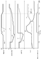
- It is a speed diagram of the speed change mechanism during execution of slip rotation speed control concerning the embodiment of the present invention (a) shows the state where the state of engagement of the 2nd brake corresponds to a command, and (b) is the 1st. The state of engagement of the two brakes is different from the command.
- It is a time chart which shows an example of the operation state of each part at the time of performing slip rotation speed control concerning the embodiment of the present invention. It is a time chart which shows another example of the operation state of each part at the time of performing slip rotation speed control which concerns on embodiment of this invention. It is a time chart which shows an example of the operation state of each part at the time of performing slip rotation speed control concerning a comparative example. It is a flowchart which shows the process sequence of slip rotational speed control which concerns on embodiment of this invention.
- the control device 3 targets the drive device 1 as a control target.
- the drive device 1 is a vehicle drive for driving a vehicle (hybrid vehicle) provided with both the internal combustion engine E and the rotating electrical machine MG as a driving force source for the wheels 15.
- This is a device (drive device for a hybrid vehicle).
- the control device 3 according to the present embodiment will be described in detail.
- driving connection means a state in which two rotating members are connected so as to be able to transmit a driving force (synonymous with torque) so that the two rotating members rotate integrally. Or a state in which the two rotating members are connected so as to be able to transmit a driving force via one or more transmission members (shaft, gear mechanism, belt, etc.). Note that such a transmission member may include an engagement device that selectively transmits rotation and driving force. Further, in the case of “driving connection” for each rotating element of the differential gear device, the state where the three or more rotating elements included in the differential gear device are drivingly connected without intervening other rotating elements. Shall point.
- the “engaged state” means a state where transmission torque is generated in the engagement device, that is, the transmission torque capacity of the engagement device is zero. It is a larger state. Therefore, when the engagement device is engaged, rotation and torque are transmitted between the engagement members of the engagement device (between the input side engagement member and the output side engagement member).
- the transmission torque capacity is the maximum torque that the friction engagement device can transmit by friction
- the transmission torque capacity is the engagement pressure (input side engagement) of the friction engagement device. The pressure changes in proportion to the pressure that presses the combined member and the output side engaging member against each other.
- the “engaged state” includes a “directly engaged state” and a “slip engaged state”.
- the “directly engaged state” is a “engaged state” and a state in which there is no rotational speed difference (slip) between the engaging members of the engaging device (a state in which the rotational speed difference is zero). is there.
- the “slip-engaged state (sliding-engaged state)” is an “engaged state” and a state in which there is a rotational speed difference (slip) between the engaging members of the engaging device (rotational speed). The difference is greater than zero).
- the “released state” is a state where no transmission torque is generated in the engagement device, that is, a state where the transmission torque capacity of the engagement device is zero. Therefore, when the engagement device is released, rotation and torque are not substantially transmitted between the engagement members of the engagement device.
- the transmission torque may be generated by dragging the engagement members (friction members). In the present specification, such drag torque generated when the engagement pressure is zero is not included in the transmission torque when the engagement state is classified, and is applied when a command for generating the transmission torque is not issued.
- the state in which transmission torque is generated by dragging the combined members is also included in the “released state”.
- release pressure represents a pressure at which the engagement device is in a state of being constantly released.
- Release boundary pressure represents a pressure at which a boundary state between a state where the engagement device is released and a state where the engagement device is slip-engaged.
- engagement boundary pressure represents a pressure that is a boundary state between the state where the engagement device is slip-engaged and the state where it is directly coupled.
- complete engagement pressure represents a pressure at which the engagement device is in a state of being directly and directly engaged.
- the “slip engagement pressure” represents a pressure at which the engagement device is in a slip engagement state, and is specifically set to a pressure higher than the release boundary pressure and lower than the engagement boundary pressure.
- the “direct engagement pressure” represents a pressure at which the engagement device is in a direct engagement state, and is specifically set to a pressure higher than the engagement boundary pressure and lower than the complete engagement pressure.
- the complete engagement pressure is, for example, a line pressure generated by the hydraulic control device 26.
- the drive device 1 includes a speed change mechanism 13 in a power transmission path connecting the rotating electrical machine MG and the wheels 15, and a plurality of engagement devices are provided in the power transmission path.
- Each of the plurality of engagement devices is an engagement device (transmission engagement device) provided in the transmission mechanism 13 or an engagement device provided separately from the transmission mechanism 13.
- each of the plurality of engagement devices provided in the power transmission path between the rotating electrical machine MG and the wheel 15 is a shift engagement device.
- the internal combustion engine E is drivably coupled to the rotating electrical machine MG via a disconnection clutch C0.
- the drive device 1 is configured so that, in order from the side of the internal combustion engine E along the power transmission path connecting the internal combustion engine E and the wheels 15, the separation clutch C 0, the rotating electrical machine MG, and the speed change mechanism 13. It has.
- the drive device 1 transmits the output torque of one or both of the internal combustion engine E and the rotating electrical machine MG to the wheels 15 to drive the vehicle.
- the separation clutch C0 corresponds to the “third engagement device” in the present invention.
- the internal combustion engine E is a prime mover (such as a gasoline engine) that is driven by the combustion of fuel inside the engine to extract power. As shown in FIG. 1, the internal combustion engine E is drivingly connected to an input shaft I as an input member of the driving device 1. In this example, an internal combustion engine output shaft such as a crankshaft of the internal combustion engine E is drivingly connected so as to rotate integrally with the input shaft I.
- the internal combustion engine E is drivably coupled to the rotating electrical machine MG via a disconnection clutch C0.
- the internal combustion engine E is not provided with a starter / alternator, and when the internal combustion engine E is started, the output of the internal combustion engine E is driven by the driving force of the rotating electrical machine MG transmitted via the disconnection clutch C0. The shaft is driven to rotate (cranking).
- the disconnection clutch C0 is provided in a power transmission path between the internal combustion engine E and the rotating electrical machine MG, and functions as an internal combustion engine disconnecting engagement device for disconnecting the internal combustion engine E from the wheel 15 and the rotating electrical machine MG.
- the input side engaging member of the disconnecting clutch C0 is drivingly connected to the input shaft I without passing through the output side engaging member of the disconnecting clutch C0, and the output side of the disconnecting clutch C0.
- the engaging member is drivingly connected to the intermediate shaft M without passing through the input side engaging member of the disconnecting clutch C0.
- a state where the internal combustion engine E and the rotating electrical machine MG are connected and a state where the internal combustion engine E and the rotating electrical machine MG are separated are selectively realized according to the state of engagement of the disconnecting clutch C0. That is, when the disconnecting clutch C0 is engaged, the internal combustion engine E and the rotating electrical machine MG are connected, and when the disconnecting clutch C0 is released, the internal combustion engine E and the rotating electrical machine MG are separated. It becomes a state.
- connection maintaining state is a state in which the connection between the two target rotating members is maintained (connection maintaining state). In this connection maintaining state, driving force is transmitted between the two rotating members.
- the “separated state” is a state where the connection between the two target rotating members is released (connection release state). In this disconnected state, the driving force is not substantially transmitted between the two rotating members.
- the drag torque described above is not considered. That is, when the engaging device interposed between the two target rotating members is in an engaged state (specifically, a directly engaged state or a slip engaged state), the two rotating members Are connected, and when the engagement device interposed between the two target rotating members is released, the two rotating members are separated.
- the disconnecting clutch C0 is configured as a friction engagement device.
- the disconnecting clutch C0 is configured as a hydraulically driven engagement device (for example, a wet multi-plate clutch) having a hydraulic servo mechanism that operates according to the supplied hydraulic pressure.
- the engagement pressure of the clutch C0 changes in proportion to the hydraulic pressure supplied to the disconnecting clutch C0. That is, in this embodiment, the magnitude of the transmission torque capacity of the disconnecting clutch C0 changes in proportion to the magnitude of the hydraulic pressure supplied to the disconnecting clutch C0.
- the rotating electrical machine MG is provided in a power transmission path between the separation clutch C0 and the wheel 15 (specifically, between the separation clutch C0 and the transmission mechanism 13).
- the rotating electrical machine MG includes a rotor and a stator, and can perform both a function as a motor (electric motor) and a function as a generator (generator).
- the rotor of the rotating electrical machine MG is drivingly connected so as to rotate integrally with an intermediate shaft M as a speed change input shaft.
- the rotating electrical machine MG is electrically connected to the power storage device 21 via an inverter device 24 (DC / AC converter).
- the rotating electrical machine MG is powered by receiving power from the power storage device 21 or supplies the power storage device 21 with power generated (regenerated) by the output torque of the internal combustion engine E or the inertial force of the vehicle.
- the power storage device 21 is configured by, for example, a battery or a capacitor.
- the speed change mechanism 13 includes an output shaft O that is drivingly connected to the wheel 15, and changes the rotation speed of the intermediate shaft M as a speed change input shaft based on a speed change ratio (gear ratio) to output the output shaft O as a speed change output shaft To communicate.
- the “transmission ratio” is the ratio of the rotational speed of the intermediate shaft M (transmission input shaft) to the rotational speed of the output shaft O (transmission output shaft).
- the output shaft O is drivingly connected to the left and right wheels 15 via the output differential gear device 14, and the torque transmitted to the output shaft O is distributed by the output differential gear device 14 to be divided into two. It is transmitted to the wheel 15.
- the speed change mechanism 13 is an automatic stepped speed change mechanism configured to be able to switch between a plurality of speed stages having different speed ratios.
- the transmission mechanism 13 includes a gear mechanism and a plurality of shift engagement devices that engage or release the rotation elements of the gear mechanism. The gear position is switched by controlling the state of each engagement.
- Each of the shift engagement devices is disposed in a power transmission path that connects the rotating electrical machine MG and the wheel 15. As shown in FIG. 2, the shift engagement device includes a first clutch C1, a second clutch C2, a third clutch C3, a first brake B1, and a second brake B2. Each of these shift engagement devices is also configured as a friction engagement device.
- each of the shifting engagement devices is configured as a hydraulically driven engagement device (for example, a wet multi-plate clutch or a wet multi-plate brake) having a hydraulic servo mechanism that operates according to the supplied hydraulic pressure.
- a hydraulically driven engagement device for example, a wet multi-plate clutch or a wet multi-plate brake
- the engagement pressure and the transmission torque capacity of the shift engagement device change in proportion to the hydraulic pressure supplied to the shift engagement device.
- the speed change mechanism 13 is configured by combining two differential gear devices, a first differential gear device PG1 and a second differential gear device PG2.
- the first differential gear device PG1 is constituted by a single pinion type planetary gear mechanism having a first sun gear S1, a first carrier CA1, and a first ring gear R1. That is, the first differential gear device PG1 has a first rotating element X1, a second rotating element X2, and a third rotating element X3 in order of rotational speed, and the first sun gear S1 constitutes the first rotating element X1.
- the first carrier CA1 constitutes the second rotating element X2, and the first ring gear R1 constitutes the third rotating element X3.
- in order of rotational speed means “in order of high or low rotational speed in the rotational state of each rotating element”, and is arranged in a speed diagram (collinear diagram, FIG. 5) of each rotating element. It is equal to the order (order in which the axes corresponding to the rotating elements are arranged).
- the second differential gear device PG2 is constituted by a Ravigneaux type planetary gear mechanism having a second sun gear S2, a third sun gear S3, a second carrier CA2, and a second ring gear R2.
- the second differential gear device PG2 includes a single pinion type planetary gear mechanism formed by the second sun gear S2, the second carrier CA2, and the second ring gear R2, a third sun gear S3, and a second carrier CA2.
- the double pinion type planetary gear mechanism formed by the second ring gear R2 is configured to share a part of the pinion gear, the carrier, and the ring gear.
- the second differential gear device PG2 includes the first rotation element X1, the second rotation element X2, the third rotation element X3, and the fourth rotation element X4 in the order of the rotation speed, and the second sun gear S2 is the first sun gear S2.
- the first rotating element X1 is configured
- the second carrier CA2 is configured as the second rotating element X2
- the second ring gear R2 is configured as the third rotating element X3
- the third sun gear S3 is configured as the fourth rotating element X4. Yes.
- the third rotating element X3 (first ring gear R1 in this example) of the first differential gear device PG1 is drivingly connected to the intermediate shaft M, and is drivingly connected to rotate integrally with the intermediate shaft M in this example.
- the third rotating element X3 (second ring gear R2 in this example) of the second differential gear device PG2 is drivingly connected to the output shaft O, and is drivingly connected to rotate integrally with the output shaft O in this example.
- the second rotating element X2 (first carrier CA1 in this example) of the first differential gear device PG1 is connected to the fourth rotating element X4 (first in this example) of the second differential gear device PG2 via the first clutch C1.
- the third sun gear S3) is drivingly connected to the first rotating element X1 (second sun gear S2 in this example) of the second differential gear device PG2 via the third clutch C3.
- the third rotating element X3 (first ring gear R1 in this example) of the first differential gear device PG1 is connected to the second rotating element X2 (second wheel in this example) of the second differential gear device PG2 via the second clutch C2. It is drivingly connected to a two carrier CA2).
- the first rotating element X1 (first sun gear S1 in this example) of the first differential gear device PG1 is fixed to a case (transmission mechanism case) as a non-rotating member.
- the first rotating element X1 (second sun gear S2 in this example) of the second differential gear device PG2 is selectively fixed to the case by the first brake B1.
- the second rotary element X2 (second carrier CA2 in this example) of the second differential gear device PG2 is selectively fixed to the case by the second brake B2.
- the speed change mechanism 13 controls to a state in which a specific two of the plurality of speed change engagement devices are engaged (basically, a direct connection state). Control is performed in a state in which the others are released, and the target shift stage at each time point is formed.
- “ ⁇ ” indicates that the shift engagement device is controlled to be engaged (basically, a direct engagement state)
- “No symbol” indicates that the shift engagement device is released. It shows that it is controlled to the state.
- first speed is the first speed
- second speed is the second speed
- third speed is the third speed
- fourthth is the fourth speed
- 5th is the fifth speed
- 6th represents the sixth speed
- forward gears forward gears
- Rev represents a reverse gear (reverse gear).
- the gear ratio of the forward gear is set so as to decrease stepwise from the first speed to the sixth speed.
- the first speed is formed by controlling the first clutch C1 to be engaged and controlling the second brake B2 to be engaged.
- the second speed is formed by controlling the first clutch C1 to be engaged and controlling the first brake B1 to be engaged.
- FIG. 5A shows the operating state of the speed change mechanism 13 at the first speed.
- the first ring gear R1 of the first differential gear device PG1 has an output torque of at least one of the internal combustion engine E and the rotating electrical machine MG (for example, the rotating electrical machine torque output by the rotating electrical machine MG). Tmg) is transmitted.
- the torque transmitted to the first ring gear R1 of the first differential gear device PG1 is the first differential gear device PG1. This is transmitted as the input torque T1 to the third sun gear S3 of the second differential gear device PG2 via the carrier CA1.
- the second carrier CA2 fixed to the second brake B2 receives the reaction force of the positive input torque T1 acting on the third sun gear S3, so that the traveling torque To (traveling resistance) is generated from the wheels 15.
- the input torque T1 is transmitted to the transmitted second ring gear R2.
- the same direction as the rotation direction of the internal combustion engine E is defined as “positive” and the opposite direction is defined as “negative”.
- Each speed diagram shown in FIG. 5 and FIG. 6 referred to later represents the operating state of the speed change mechanism 13, and the vertical axis corresponds to the rotational speed of each rotating element. That is, “0” described corresponding to the vertical axis indicates that the rotation speed is zero, the upper side is positive rotation (rotation speed is positive), and the lower side is negative rotation (rotation speed is negative). It is. Further, in FIG. 5, a state where the rotating element is fixed by the brake is represented by a white “X” -shaped symbol.
- the control device 3 includes a plurality of functional units.
- the plurality of functional units are configured to exchange information with each other.
- the control device 3 includes an arithmetic processing device such as a CPU as a core, and includes a storage device such as a RAM and a ROM.
- Each functional unit of the control device 3 is configured by software (program) stored in a ROM or the like, hardware such as a separately provided arithmetic circuit, or both.
- the control device 3 is configured to be able to acquire information on detection results from the sensors Se1 to Se6 provided in each part of the vehicle.
- the first rotation sensor Se1 is a sensor that detects the rotation speed of the internal combustion engine E or the input shaft I.
- the second rotation sensor Se2 is a sensor that detects the rotational speed of the rotor of the rotating electrical machine MG or the intermediate shaft M, and is configured by a resolver in this example.
- the third rotation sensor Se3 is a sensor that detects the rotation speed of the output shaft O. The control device 3 derives the rotation speed or the vehicle speed of the wheel 15 based on the detection result of the third rotation sensor Se3.
- the accelerator opening sensor Se4 is a sensor that detects the accelerator opening by detecting the operation amount of the accelerator pedal 90 provided in the vehicle.
- the power storage device sensor Se ⁇ b> 5 is a sensor that detects the state of the power storage device 21. In this example, the power storage device sensor Se ⁇ b> 5 detects the SOC (state of charge) or the amount of power stored in the power storage device 21 and the temperature of the power storage device 21.
- the brake operation sensor Se6 is a sensor that detects an operation amount of the brake pedal 91 provided in the vehicle.
- the control device 3 is configured to be able to exchange information with the internal combustion engine control unit 23 that controls the operation of the internal combustion engine E.
- the internal combustion engine control unit 23 controls the operating point (output torque and rotational speed) of the internal combustion engine E based on a command from the control device 3. For example, when the target value (target torque) of the output torque is instructed from the control device 3, the internal combustion engine control unit 23 is a control that causes the output torque of the internal combustion engine E to follow (or approach) the target torque. Perform torque control.
- the internal combustion engine control unit 23 performs start control and stop control of fuel injection and ignition based on a command from the control device 3, and changes the state of the internal combustion engine E between the operating state (starting state) and the stopped state. Switch.
- the hydraulic control unit 34 is a functional unit that controls the supply of hydraulic pressure to each engagement device (C0, C1, C2, C3, B1, B2).
- the hydraulic control unit 34 outputs a hydraulic pressure command to each engagement device in accordance with the travel mode to be realized and the shift speed to be formed, and controls the hydraulic pressure supplied to each engagement device via the hydraulic control device 26.
- the engagement state of each engagement device is controlled to one of a directly engaged state, a slip engaged state, and a released state according to the supplied hydraulic pressure.
- the hydraulic pressure control device 26 includes a proportional solenoid and the like, and can continuously control the hydraulic pressure supplied to each engagement device in accordance with the hydraulic pressure command of the hydraulic pressure control unit 34.
- the hydraulic control unit 34 controls the line pressure via the hydraulic control device 26.
- the hydraulic control device 26 includes a line pressure control valve (for example, a pressure regulator valve) that controls the discharge pressure of the hydraulic pump to the line pressure, and the hydraulic control unit 34 A command for controlling the pressure regulation value (control target value) of the pressure control valve is output to the hydraulic control device 26.
- the line pressure is a hydraulic pressure in which the discharge pressure of the hydraulic pump is regulated, and is necessary for a device to which the discharge oil of the hydraulic pump is supplied (in this embodiment, the speed change mechanism 13, the separation clutch C0, the rotating electrical machine MG). Hydraulic. This required oil pressure is always calculated from the state of the speed change mechanism 13 (whether or not the speed is being changed), torque of the driving force source, vehicle speed, throttle opening, oil pressure, and the like.
- the hydraulic control unit 34 executes control to increase the line pressure when the internal combustion engine start control is executed, and the internal combustion engine The line pressure during execution of the engine start control is increased as compared with that before execution of the internal combustion engine start control. Note that the hydraulic control unit 34 increases the line pressure also when the transmission mechanism 13 changes the gear position, for example.
- the hydraulic control device 26 corresponds to each of the engagement devices, and controls a hydraulic control valve (for example, a hydraulic pressure in this example) supplied to each engagement device (for example, oil pressure).
- a hydraulic control valve for example, a hydraulic pressure in this example
- the hydraulic control valve corresponding to the shift engagement device receives the supply of the line pressure and outputs the hydraulic pressure as the operating pressure to the shift engagement device. It is configured.
- the hydraulic control unit 34 controls the shift engagement device to be in a directly engaged state in order to form a shift stage, basically, with respect to the shift engagement device
- the hydraulic control device 26 is controlled so that the line pressure is supplied as the operating pressure. That is, when the hydraulic pressure control valve that controls the hydraulic pressure supplied to the gear shift engagement device is controlled to be in a state where the gear shift engagement device is directly engaged, the valve opening degree is basically the full opening degree.
- the hydraulic pressure control unit 34 basically controls the hydraulic pressure supplied to the gearshift engagement device when controlling the gearshift engagement device to be in a directly coupled state.
- a constant pressure control is executed to set the command value of the output hydraulic pressure for the hydraulic control valve to a constant pressure higher than the line pressure.
- the constant pressure control is executed by the second engagement control unit 32 in cooperation with the hydraulic control unit 34 when the shifting engagement device is a second engagement device described later. Therefore, in the present embodiment, when the line pressure is changed within the range of the predetermined pressure or less, the hydraulic pressure supplied to the gear shift engagement device controlled to be in the direct engagement state is changed after the change. The line pressure is automatically adjusted.
- the opening of the hydraulic control valve that controls the hydraulic pressure supplied to the gear shift engagement device is maintained at the fully open position, for example, when the line pressure increases, the gear is supplied to the gear shift engagement device.
- the hydraulic pressure increases accordingly.
- the hydraulic pressure supplied to the gearshift engaging device that is controlled to be in a directly engaged state is adjusted to the fixed pressure.
- the constant pressure when executing the constant pressure control is set to a pressure higher than the line pressure.
- the line pressure in this case is, for example, a command value for the line pressure generated by the hydraulic control unit 34.
- the line pressure in this case is, for example, the current line pressure, that is, the line pressure at the start of execution of the constant pressure control.
- the constant pressure can be set to, for example, an upper limit value of a line pressure adjustment range by the hydraulic control unit 34 or a value higher than that.
- the hydraulic control valve that controls the hydraulic pressure supplied to the gearshift engagement device is configured as a valve that is directly controlled by the command value of the output hydraulic pressure from the hydraulic control unit 34 or the output from the hydraulic control unit 34. It is configured as a valve that is controlled by a signal oil pressure from another valve that is directly controlled by a hydraulic pressure command value.
- the hydraulic control unit 34 controls the operation of each engagement device by torque control or rotational speed control.
- the “torque control” is a control in which a target value (target transmission torque capacity) of the transmission torque capacity of the engagement device is set, and the transmission torque capacity of the engagement device follows (or approaches) the target transmission torque capacity.
- “Rotational speed control” sets a target value (target rotational speed difference) of a rotational speed difference between two engaging members engaged by the engaging device, and sets a transmission torque capacity of the engaging device. This control is a control to make the rotational speed difference follow (or approach) the target rotational speed difference.
- the rotational speed control when the rotational speed of one of the two engaging members is uniquely determined by another factor (for example, the vehicle speed), the rotational speed of the other engaging member is set as a target. The control is to follow (or approach) the rotational speed.
- the rotating electric machine control unit 33 is a functional unit that controls the operation of the rotating electric machine MG.
- the rotating electrical machine control unit 33 controls the operating point (output torque and rotational speed) of the rotating electrical machine MG by controlling the inverter device 24.
- the rotating electrical machine control unit 33 performs operation control of the rotating electrical machine MG by torque control or rotational speed control.
- torque control is control in which a target value (target torque) of the output torque of the rotating electrical machine MG is set and the output torque of the rotating electrical machine MG follows (or approaches) the target torque.
- “Rotational speed control” sets a target value (target rotational speed) of the rotational speed of the rotating electrical machine MG, controls the output torque of the rotating electrical machine MG, and causes the rotational speed of the rotating electrical machine MG to follow the target rotational speed. (Or approach) control.
- the internal combustion engine E and the rotating electrical machine MG are basically controlled such that the sum of the output torque of the internal combustion engine E and the output torque of the rotating electrical machine MG is in a balanced relationship equal to the required torque (vehicle required torque).
- the required torque is a torque required to be transmitted to the wheel 15.
- the control device 3 determines the required torque by referring to a required torque map (not shown) based on the vehicle speed, the accelerator opening, the state of the power storage device 21 (for example, SOC), and the like. Further, the control device 3 determines a gear stage to be formed by the transmission mechanism 13 by referring to a shift map (not shown) based on the vehicle speed, the accelerator opening, and the like, for example.
- the control device 3 considers, for example, the necessity of charging the power storage device 21 and the energy efficiency of the entire vehicle, and the internal combustion engine required torque that is the output torque required for the internal combustion engine E (that is, within the required torque).
- a share of the internal combustion engine E) and a rotating electrical machine required torque that is an output torque required for the rotating electrical machine MG (that is, a share of the requested torque by the rotating electrical machine MG) are determined.
- the rotating electrical machine required torque is set to a negative torque that is required to generate the target generated power.
- the absolute value of this negative torque is referred to as “power generation torque”.
- the internal combustion engine required torque is set to a value larger than the required torque by the power generation torque.
- the target generated torque that is the target value of the generated torque is obtained by dividing the target generated power by the rotational speed (target value or detected value) of the rotating electrical machine MG. Note that the necessity of charging the power storage device 21 is determined based on the SOC of the power storage device 21.
- the control device 3 basically selects the electric travel mode when the internal combustion engine required torque is zero, and selects the hybrid travel mode when the internal combustion engine required torque is not zero.
- the disconnection clutch C0 is controlled to be released, and the torque of the rotating electrical machine MG is transmitted to the wheels 15 to cause the vehicle to travel.
- the clutch C0 for disengagement is controlled to be in an engaged state (basically, a state in which it is directly engaged), and the torques of both the internal combustion engine E and the rotating electrical machine MG are transmitted to the wheels 15.
- the rotating electrical machine MG is controlled to output a negative torque (power generation torque), and power is generated by the rotating electrical machine MG.
- the slip rotation speed control unit 30 is a functional unit that executes slip rotation speed control.
- the slip rotation speed control unit 30 executes slip rotation speed control as target control.
- the “slip rotation speed control” is a first engagement device that is one of a plurality of engagement devices provided in a power transmission path that connects the rotating electrical machine MG and the wheel 15 (in a specific example described later, Control the engagement pressure of the second brake B2) to be the slip engagement pressure, and set the target rotational speed Nt so as to maintain the first engagement device in the slip engagement state. In this control, the rotation speed is brought close to the target rotation speed Nt.
- the speed change engagement device of the speed change mechanism 13 is arranged in the power transmission path that connects the rotating electrical machine MG and the wheel 15, and among the plurality of speed change engagement devices.
- One is a first engagement device.
- one of the two shift engagement devices controlled to be engaged to form a shift stage is a first engagement device, and the other is a second engagement device described later. Is done.
- the shift speed to be formed during the execution of the slip rotation speed control is the first speed (1st)
- one of the first clutch C1 and the second brake B2 is the first engagement device, and the other Is the second engagement device.
- the slip rotation speed control unit 30 determines the execution of the slip rotation speed control when a predetermined execution condition (start condition) of the slip rotation speed control is satisfied.
- start condition a predetermined execution condition
- the first engagement device which is one of the gear engagement devices controlled to be engaged to form the gear stage at that time
- the engaged state is controlled. Therefore, even when torque fluctuation is transmitted from the rotating electrical machine MG side to the transmission mechanism 13, transmission of the torque fluctuation to the wheels 15 can be suppressed.
- the specific control includes internal combustion engine start control for starting the stopped internal combustion engine E, which will be described later as a specific example.
- the rotation speed of the intermediate shaft M or the rotating electrical machine MG can be controlled to a speed different from the synchronous rotation speed Ns.
- the synchronous rotational speed Ns is controlled so that both of the two shift engagement devices controlled to be engaged in order to form the gear stage at that time are in a directly connected state.
- the rotational speed of the intermediate shaft M is determined based on the integrated value of the vehicle speed and the gear ratio. Even if the synchronous rotational speed Ns is lower than the lower limit value of the rotational speed of the intermediate shaft M that allows the internal combustion engine E to continue the self-sustained operation (hereinafter referred to as “specific low speed state”), the slip rotational speed.
- the rotation speed of the intermediate shaft M can be controlled to a rotation speed equal to or higher than the lower limit value.
- the slip rotation speed control is executed, so that the disconnecting clutch C0 is controlled to be in a directly engaged state, and the rotating electrical machine MG generates power by the output torque of the internal combustion engine E.
- the direct engagement power generation control can be executed.
- the execution condition of the slip rotation speed control is satisfied even when the execution condition of the direct engagement power generation control in the specific low speed state is satisfied.
- the slip rotation speed control unit 30 determines the end of the slip rotation speed control when a predetermined slip rotation speed control end condition is satisfied.
- the slip rotation speed control end condition is a condition based on the rotation speed difference between the two members engaged by the first engagement device. Specifically, during the execution of the slip rotation speed control, basically, the rotation speed difference between the two members engaged by the first engagement device is equal to or greater than a predetermined end determination threshold value. To be controlled. The rotational speed difference at this time is set according to the content of other control (for example, internal combustion engine start control) executed during the execution of the slip rotational speed control.
- the control for reducing the rotation speed difference between the two members engaged by the first engagement device is executed. And when the said rotational speed difference becomes less than said completion
- the end determination threshold value can be set to a value included in the range of 10 [rpm] to 100 [rpm], for example.
- the first engagement control unit 31 is a functional unit that controls the engagement pressure of the first engagement device via the hydraulic control unit 34 during execution of slip rotation speed control.
- the second brake B2 is the first engagement device.
- the first engagement control unit 31 executes slip engagement control that puts the first engagement device into a slip-engaged condition on the condition that execution of slip rotation speed control is determined. Specifically, the first engagement control unit 31 is in a first engagement state when the first engagement device is in a state different from the slip engagement state (hereinafter referred to as “non-slip state”). Transition control for shifting the device from the non-slip state to the slip-engaged state is executed. In addition, this transition control is abbreviate
- the 1st engagement control part 31 performs the maintenance control which maintains the 1st engagement apparatus in the state which slip-engaged after transfering to the state which slip-engaged the 1st engagement apparatus.
- the non-slip state includes a directly engaged state and a released state.
- the first engagement control unit 31 performs control to set the engagement pressure of the first engagement device to the slip engagement pressure as the target control (the engagement pressure of the first engagement device is set to the slip engagement). Control to issue a command to achieve a combined pressure).
- the control device 3 executes at least control for setting the engagement pressure of the first engagement device to the slip engagement pressure, and in this embodiment, the first engagement device is further slip-engaged.
- the target rotational speed Nt is set so as to maintain the state, and control is performed to bring the rotational speed of the rotating electrical machine MG closer to the target rotational speed Nt.
- the first engagement control unit 31 continues the maintenance control for maintaining the first engagement device in the slip-engaged state until the end of the target control (here, the slip rotation speed control) is determined. Execute. And the 1st engagement control part 31 performs the slip cancellation
- the slip release control by the first engagement control unit 31 is a direct engagement control for bringing the first engagement device into a direct engagement state.
- the first engagement control unit 31 when changing the engagement pressure of the first engagement device, gradually increases the engagement pressure toward the target value (in other words, gradually increases, or Sweep up) or gradually decrease (in other words, gradually decrease or sweep down).
- the slip release control of the first engagement device is a direct engagement control that changes the first engagement device from the slip engagement state to the direct engagement state.
- the engagement control unit 31 performs control to gradually increase the engagement pressure of the first engagement device from the slip engagement pressure to the direct engagement pressure during execution of the direct engagement control. That is, the direct engagement control of the first engagement device is a control for increasing (in this example, gradually increasing) the command value of the engagement pressure of the first engagement device from the slip engagement pressure to the direct engagement pressure.
- the second engagement control unit 32 is a functional unit that controls the engagement pressure of the second engagement device via the hydraulic control unit 34 during execution of the slip rotation speed control.
- the second engagement device is an engagement device that is different from the first engagement device, and is an engagement device that is controlled to be in a directly engaged state during the execution of the slip rotation speed control.
- the first clutch C1 is a second engagement device.
- the second engagement control unit 32 sets the engagement pressure of the second engagement device to be equal to or higher than the first engagement pressure during execution of target control (here, slip rotation speed control).
- target control here, slip rotation speed control
- the control is performed so that the set pressure Pa during control is set to be equal to or lower than the second engagement pressure.
- the set pressure Pa during control is, for example, a pressure equal to or lower than the second engagement pressure, and is set to a pressure obtained by multiplying the first engagement pressure by a predetermined coefficient. This coefficient can be a value included in the range of “1.1” to “1.3”, for example.
- the first engagement pressure is a state in which a required torque, which is a torque required to be transmitted to the wheel 15, is transmitted to the wheel 15 (hereinafter referred to as “requested torque transmission state”).
- This is the lower limit of the engagement pressure at which the engagement device can be maintained in the state of being directly coupled. That is, the first engagement pressure is the engagement boundary pressure of the second engagement device in the required torque transmission state.
- the second engagement pressure is obtained by directly engaging the second engagement device in a state where the maximum output torque of the rotating electrical machine MG is transmitted to the wheel 15 (hereinafter referred to as “maximum output torque transmission state”). It is the lower limit engagement pressure that can be maintained in the state. That is, the second engagement pressure is an engagement boundary pressure of the second engagement device in the maximum output torque transmission state.
- the first engagement pressure is: This is an engagement pressure that makes the transmission torque capacity of the second engagement device equal to the first transmission torque in a state in which the second engagement device is in direct engagement.
- the first transmission torque depends on the gear ratio (in other words, the sharing ratio) determined based on the position of the second engagement device in the power transmission path connecting the rotating electrical machine MG and the wheel 15 and the required torque. Determined.
- the engagement pressure that makes the transmission torque capacity of the second engagement device equal to the first transmission torque depends on the first transmission torque and the configuration of the second engagement device (for example, the area and number of friction plates). It depends on your needs.
- the second engagement pressure is the second engagement device in the state where the second engagement device is directly connected. Is an engagement pressure that equalizes the second transmission torque.
- the second transmission torque is determined according to the gear ratio determined based on the position of the second engagement device in the power transmission path connecting the rotary electric machine MG and the wheel 15 and the maximum output torque of the rotary electric machine MG.
- the engagement pressure that makes the transmission torque capacity of the second engagement device equal to the second transmission torque depends on the second transmission torque and the configuration of the second engagement device (for example, the area and number of friction plates). It depends on your needs.
- the maximum output torque of the rotating electrical machine MG is variably set according to the rotational speed of the rotating electrical machine MG and variably set according to the power that can be supplied from the power storage device 21.
- the power that can be supplied from the power storage device 21 is limited according to the state (SOC, temperature, etc.) of the power storage device 21.
- the second engagement device is specified as one engagement device, the first engagement pressure is determined based on the required torque, and the second engagement pressure is determined based on the rotational speed of the rotating electrical machine MG and the power storage. It is determined based on the state of the device 21.
- the second engagement control unit 32 executes control to set the engagement pressure of the second engagement device to the set pressure Pa during control on the condition that execution of slip rotation speed control is determined. Specifically, the second engagement control unit 32 changes the engagement pressure (specifically, a command value) of the second engagement device from the engagement pressure at that time to the set pressure Pa during control. The second engagement control unit 32 continues to perform control to set the engagement pressure of the second engagement device to the setting pressure Pa during control until the end of the slip rotation speed control is determined. Then, the second engagement control unit 32 sets the engagement pressure of the second engagement device to a pressure different from the set pressure Pa during control (hereinafter referred to as “set pressure after control” on condition that the slip rotation speed control is finished). Pb ") is executed. Specifically, the second engagement control unit 32 changes the engagement pressure (specifically, a command value) of the second engagement device from the setting pressure Pa during control to the setting pressure Pb after control.
- set pressure after control a pressure different from the set pressure Pa during control
- the post-control set pressure Pb is set higher than the set pressure Pa during control. That is, in the present embodiment, the control for changing the engagement pressure of the second engagement device from the mid-control set pressure Pa to the post-control set pressure Pb is the pressure increase control for increasing the engagement pressure.
- the post-control set pressure Pb is, for example, higher than the mid-control set pressure Pa, and is set to a pressure obtained by multiplying the first engagement pressure by a predetermined coefficient. This coefficient can be a value included in the range of “1.3” to “1.5”, for example.
- the control for increasing the set pressure Pa to the post-control set pressure Pb is hereinafter referred to as “directly connected pressure increasing control”.
- the 2nd engagement control part 32 performs the control which gradually increases the engagement pressure of a 2nd engagement apparatus from the control setting pressure Pa to the post-control setting pressure Pb as direct connection pressure increase control.
- the direct coupling pressure increase control is a control for increasing (in this example, gradually increasing) the command value of the engagement pressure of the second engagement device from the control set pressure Pa to the post-control set pressure Pb.
- the second engagement control unit 32 executes the direct connection pressure increasing control while the first engagement control unit 31 performs the above-described direct connection control.
- the second engagement control unit 32 is configured to start the direct connection pressure increase control in accordance with the start of the direct connection control by the first engagement control unit 31. Further, the second engagement control unit 32 increases the engagement pressure of the second engagement device so that the direct coupling pressure increase control is terminated in accordance with the termination of the direct coupling control by the first engagement control unit 31. It is configured as follows.
- FIG. 5A shows a state where both the first clutch C ⁇ b> 1 and the second brake B ⁇ b> 2 are controlled to be in a direct coupling engagement, and the first speed stage is formed in the transmission mechanism 13.
- “ ⁇ 1” represents the gear ratio between the first sun gear S1 and the first ring gear R1 of the first differential gear device PG1
- “ ⁇ 2” represents the second differential gear device. This represents the gear ratio between the third sun gear S3 and the second ring gear R2 of PG2.
- the actual transmission torque transmitted by the first clutch C1 is equal to the input torque T1
- the input torque T1 is equal to the rotating electric machine.
- the first transmission torque is a value obtained by multiplying the rotating electrical machine required torque set according to the required torque by (1 + ⁇ 1).
- the required rotating electrical machine torque is a value obtained by multiplying the required torque by ⁇ 2 / (1 + ⁇ 1) ⁇ .
- the second transmission torque is a value obtained by multiplying the maximum output torque of the rotating electrical machine MG by (1 + ⁇ 1).
- the second engagement control unit 32 when the second engagement device is a gear shift engagement device, the second engagement control unit 32 performs constant pressure control on the second engagement device.
- the second engagement control unit 32 performs target control (in this case, according to the start request of the internal combustion engine E in a state in which the second engagement device that is the gear shift engagement device is in direct connection engagement). During execution of the slip rotation speed control) and the internal combustion engine start control, execution of constant pressure control on the second engagement device is prohibited.
- the case where the internal combustion engine start control is executed during the execution of the target control (here, the slip rotation speed control) will be described as an example. That is, in this example, during the execution of the slip rotation speed control, the internal combustion engine start control for starting the internal combustion engine E in the stopped state is executed while shifting the disengagement clutch C0 from the released state to the directly engaged state.
- the second brake B2 corresponds to the “first engagement device” in the present invention
- the first clutch C1 corresponds to the “second engagement device” in the present invention
- the first speed stage is formed in the speed change mechanism 13 during the execution of the slip rotation speed control.
- the first clutch C1 that is a hydraulically driven engagement device provided in the transmission mechanism 13 corresponds to the “second engagement device” in the present invention.
- both the first clutch C1 and the second brake B2 are controlled to be in direct engagement, and the rotational speed of the rotating electrical machine MG is the synchronous rotational speed. It corresponds to Ns.
- the second engagement device is a gear shift engagement device
- the second engagement control unit 32 is constant for the first clutch C1 that is the second engagement device in a state before time T01. Pressure control is being executed.
- the execution condition of the slip rotation speed control is also satisfied, and the first engagement control unit 31 performs the slip engagement of the second brake B2. Execute joint control.
- the internal combustion engine start condition is a condition for starting the internal combustion engine E in a stopped state.
- the internal combustion engine start condition is satisfied when the vehicle needs a torque of the internal combustion engine E.
- the driver strongly depresses the accelerator pedal 90 while the vehicle is stopped or traveling in the electric travel mode.
- the internal combustion engine start condition is satisfied when the required torque cannot be obtained only by the rotating electrical machine MG.
- the internal combustion engine start condition is also satisfied when it is necessary to start the internal combustion engine E and charge the power storage device 21.
- the state is shifted from the state where the second brake B2 is directly engaged to the state where it is slip-engaged.
- the command value of the engagement pressure of the second brake B2 is gradually decreased at a constant change rate from the direct coupling engagement pressure to the slip engagement pressure, so that the second brake B2 is slip-engaged. Transition. That is, the slip engagement control of the first engagement device (in this example, the second brake B2) reduces the command value of the engagement pressure of the first engagement device from the direct engagement pressure to the slip engagement pressure (this In this example, the control is gradually reduced.
- the second engagement control unit 32 executes control to set the engagement pressure of the first clutch C1 to the setting pressure Pa during control. Note that during the period from time T01 to time T05, the second engagement control unit 32 prohibits execution of constant pressure control for the first clutch C1.
- the engagement pressure of the first clutch C1 is decreased stepwise from the pressure higher than the set pressure Pa during control to the set pressure Pa during control in a stepwise manner.
- the set pressure Pa is changed during the control.
- the control for reducing the engagement pressure of the first clutch C1 from a pressure higher than the set pressure Pa during control to the set pressure Pa during control Hereinafter, it is referred to as “direct connection pressure reduction control”.
- the command value of the engagement pressure of the second engagement device (in this example, the first clutch C1) is reduced from a pressure higher than the set pressure Pa during control to the set pressure Pa during control (in this example, This is a control to reduce in a stepwise manner.
- the direct connection pressure reduction control may be executed at a time point before time T01 or may be executed at a time point between time T01 and time T02.
- the second engagement control unit 32 performs target control based on a start request of the internal combustion engine E in a state where the first clutch C1 (an example of the second engagement device) is directly engaged.
- the engagement pressure specifically, the command value
- target control here, , Slip rotation speed control
- direct-coupled pressure-reduction control that is lower than before the execution of the internal combustion engine start control is executed.
- the rotating electrical machine control unit 33 sets the target rotational speed Nt so as to maintain the second brake B2 in the slip-engaged state.
- the rotation speed control (specifically, the rotation speed feedback control) for setting the rotation speed of the rotating electrical machine MG to be close to the target rotation speed Nt is started.
- the target rotational speed Nt is set so that the difference from the synchronous rotational speed Ns is constant ( ⁇ N) (see FIG. 5B).
- ⁇ N is set to a value included in the range of 50 [rpm] to 200 [rpm], for example.
- the slip torque T2 generated by the transmission torque capacity of the second brake B2 receives the reaction force of the input torque T1 acting on the third sun gear S3.
- the second brake B2 slips. It is determined that the state has shifted to the engaged state.
- the slip determination threshold is set to a value included in the range of 10 [rpm] to 100 [rpm].
- it can also be set as the structure which determines with having shifted to the state which 2nd brake B2 slip-engaged when the elapsed time from time T01 reaches
- the engagement control of the disconnecting clutch C0 by the hydraulic control unit 34 is also executed.
- the separation clutch C0 is initially controlled to be in a slip engagement state, and the rotational speed of the internal combustion engine E is increased by the torque of the rotating electrical machine MG transmitted through the separation clutch C0.
- the hydraulic pressure control unit 34 is used for disconnection. Control is performed to bring the clutch C0 into a directly engaged state.
- the disconnection clutch C0 is engaged in direct engagement by gradually increasing the command value of the engagement pressure of the disconnection clutch C0 from the slip engagement pressure to the direct engagement pressure at a constant rate of change. Transition to the state.
- the synchronization determination threshold is set to a value included in a range of 10 [rpm] to 100 [rpm].
- the ignition (starting) of the internal combustion engine E is performed in a state in which the rotational speed of the internal combustion engine E is equal to or higher than a predetermined ignition possible rotational speed, and in this example, is performed between time T02 and time T03. Is done.
- control for increasing the slip engagement pressure of the second brake B2 is executed in accordance with the increase in the required torque.
- the rotating electrical machine control unit 33 executes control for gradually decreasing the target rotational speed Nt toward the synchronous rotational speed Ns.
- the first engagement control unit 31 performs the direct engagement control of the second brake B2.
- it is synchronized with the rotational speed of the rotating electrical machine MG, which is proportional to the rotational speed difference between the two members engaged by the second brake B2 (in this example, it matches the rotational speed of the second carrier CA2).
- Based on the rotational speed difference from the rotational speed Ns it is determined that the condition for ending the slip rotational speed control is satisfied on the condition that the rotational speed difference is less than a predetermined determination threshold.
- This determination threshold is the rotational speed between the two members engaged by the second brake B2 in a state where the rotational speed difference between the rotational speed of the rotating electrical machine MG and the synchronous rotational speed Ns matches the determination threshold.
- the difference is set so as to match the above-described end determination threshold value.
- This determination threshold is set to a value included in the range of 10 [rpm] to 100 [rpm], for example. Note that it is determined that the condition for ending the slip rotation speed control is satisfied when the elapsed time after starting the control for gradually decreasing the target rotation speed Nt toward the synchronous rotation speed Ns reaches a predetermined determination time. It can also be set as the structure to do.
- the second brake B2 shifts from the slip-engaged state to the directly-engaged state by the direct-engagement control of the second brake B2.
- the command value of the engagement pressure of the second brake B2 is gradually increased at a constant change rate from the slip engagement pressure to the direct engagement pressure, so that the second brake B2 is in the direct engagement state. Transition.
- the second engagement control unit 32 executes direct coupling pressure increase control in which the engagement pressure of the first clutch C1 is set to the post-control set pressure Pb.
- the command value for the engagement pressure of the first clutch C1 is gradually increased from the mid-control set pressure Pa to the post-control set pressure Pb, so that the engagement pressure of the first clutch C1 is set to the post-control set pressure Pb.
- the direct engagement control of the second brake B2 ends and the direct connection pressure increase control of the first clutch C1 ends.
- the direct coupling pressure increase control of the first clutch C1 is started in accordance with the start of the direct coupling engagement control of the second brake B2.
- the engagement of the second brake B2 during the execution of the direct engagement control is performed so that the direct connection pressure increase control of the first clutch C1 is completed in accordance with the end of the direct engagement control of the second brake B2.
- the rate of change in pressure and the rate of change in engagement pressure of the first clutch C1 during execution of direct coupling pressure increase control are set. In the example shown in FIG.
- the command value of the engagement pressure of the second brake B2 is stepped at time T05 when both the direct engagement control of the second brake B2 and the direct connection pressure increase control of the first clutch C1 are completed.
- the command value for the engagement pressure of the first clutch C1 is slightly increased stepwise is shown.
- the second engagement control unit 32 resumes the constant pressure control for the first clutch C1, which is the second engagement device, at time T05.
- FIG. 7 The example shown in FIG. 7 described so far is an example when the state of engagement of the second brake B2 matches the command.
- time T10, time T11, time T13, time T14, and time T15 in FIG. 8 correspond to and correspond to time T01, time T02, time T03, time T04, and time T05, respectively, in FIG. Similar processing is executed at each time.
- the engagement state of the second brake B2 is different from the command at time T12, and the second brake B2 is maintained in the direct engagement state after time T12. Shows the case.
- the engagement pressure of the first clutch C1 is set to the set pressure Pa during control as described above, and in this example, the set pressure Pa during control is set to a pressure smaller than the second engagement pressure.
- the second engagement pressure is the lower limit engagement that can maintain the first clutch C1 in the state of being directly coupled with the maximum output torque of the rotating electrical machine MG being transmitted to the wheel 15. Pressure.
- the first clutch C1 shifts from the direct engagement state to the slip engagement state (time T12 ').
- the first clutch C1 is brought into the slip engaged state, which is shown on the left side of FIG.
- the rotational speed of the rotating electrical machine MG can be matched (or brought close to) the target rotational speed Nt.
- the engagement pressure of the first clutch C1 is not changed, and the torque of the rotating electrical machine MG is increased to maintain the first clutch C1 in a slip-engaged state. Therefore, in FIG.
- FIG. 9 is a comparative example when the present invention is not applied, and an example in which the engagement pressure of the first clutch C1 is maintained at a pressure higher than the second engagement pressure during execution of the slip rotation speed control. Is shown. Note that time T20, time T21, time T22, time T23, time T24, and time T25 in FIG. 9 are respectively time T10, time T11, time T12, time T13, time T14, and time T15 in FIG. The same processing is executed at each corresponding time except for controlling the engagement pressure of the first clutch C1. In the comparative example shown in FIG. 9, even when the torque of the rotating electrical machine MG reaches its maximum output torque, the first clutch C1 is maintained in the directly engaged state.
- the rotating electrical machine MG continues to output a relatively large torque so that the rotational speed of the rotating electrical machine MG approaches the target rotational speed Nt higher than the synchronous rotational speed Ns.
- the ratio of the actual torque transmitted to the wheels 15 exceeding the required torque is larger than that in the application example of the present invention shown in FIG.
- the case where the internal combustion engine start control is executed during the execution of the target control (here, the slip rotation speed control) has been described as an example, but naturally the execution of the target control (here, the slip rotation speed control) is performed.
- the control of the first engagement device and the second engagement device can be performed.
- the slip rotation is performed to execute the direct coupling power generation control.
- the second engagement control unit 32 can control the engagement pressure of the second engagement device to the setting pressure Pa during control while the slip rotation speed control is being executed.
- the direct engagement power generation control is a control for causing the rotating electrical machine MG to generate power using the output torque of the internal combustion engine E by controlling the disconnecting clutch C0 to be in the direct engagement state.
- Processing procedure of slip rotation speed control A processing procedure of slip rotation speed control according to the present embodiment will be described with reference to the flowchart of FIG. Each processing procedure described below is executed by each functional unit of the control device 3.
- the second brake B2 corresponds to the “first engagement device” in the present invention
- the first clutch C1 corresponds to the “second engagement device” in the present invention.
- step # 01: Yes When the execution condition of the slip rotation speed control is satisfied (step # 01: Yes), the slip engagement control of the second brake B2 is executed (step # 02), and the direct pressure reduction control of the first clutch C1 is executed (step # 02). # 03).
- the engagement pressure of the first clutch C1 is decreased to the set pressure Pa during control (an example of the target pressure) by the direct connection pressure reduction control.
- the process of step # 02 and the process of step # 03 are started simultaneously.
- step # 04: No the process of step # 02 is continued.
- the engagement pressure of the first clutch C1 is reduced to the set pressure Pa during control by the process of step # 03, but at least before the rotation speed control of the rotating electrical machine is started in step # 05.
- the engagement pressure of C1 reaches the set pressure Pa during control.
- step # 04 When the second brake B2 is in a slip-engaged state (step # 04: Yes), the rotational speed control of the rotating electrical machine MG is started (step # 05). Until the slip rotation speed control end condition is satisfied (step # 06: No), the rotation speed control of the rotating electrical machine MG in step # 05 is continuously executed.
- step # 06: Yes When the slip rotation speed control end condition is satisfied (step # 06: Yes), the direct engagement control of the second brake B2 is executed (step # 07) and the direct connection pressure increasing control of the first clutch C1 is executed. (Step # 08), and the process ends. In the present embodiment, the process of step # 07 and the process of step # 08 are started simultaneously, and the process of step # 07 and the process of step # 08 are simultaneously ended.
- the rotor of the rotating electrical machine MG always rotates integrally with the intermediate shaft M as the speed change input shaft of the speed change mechanism 13.
- the embodiment of the present invention is not limited to this, and other devices (hereinafter referred to as “intervening devices”) are provided in the power transmission path between the rotor shaft to which the rotor of the rotating electrical machine MG is fixed and the intermediate shaft M. It is also possible to adopt a configuration in which the In other words, the power transmission path between the rotating electrical machine MG and the speed change mechanism 13 may be provided with an intervening device.
- the above-described intervening device can be configured to include a torque converter (an example of a fluid coupling) having a lock-up clutch.
- the second engagement control unit 32 may be configured to control the engagement pressure of the lockup clutch in place of the shift engagement device provided in the transmission mechanism 13.
- the lock-up clutch corresponds to the “second engagement device” in the present invention.
- a configuration including a clutch (hereinafter referred to as “fourth clutch”) may be employed.
- the first engagement control unit 31 can be configured to control the engagement pressure of the fourth clutch instead of the shift engagement device provided in the transmission mechanism 13.
- the fourth clutch corresponds to the “first engagement device” in the present invention.
- the second engagement control unit 32 may be configured to control the engagement pressure of the fourth clutch instead of the transmission engagement device provided in the transmission mechanism 13.
- the fourth clutch corresponds to the “second engagement device” in the present invention.
- the embodiment of the present invention is not limited to this, and a clutch (hereinafter referred to as “fifth clutch”) is provided in the power transmission path between the output shaft O and the output differential gear device 14. It can also be set as the structure provided.
- the first engagement control unit 31 can be configured to control the engagement pressure of the fifth clutch in place of the shift engagement device provided in the transmission mechanism 13.
- the fifth clutch corresponds to the “first engagement device” in the present invention.
- the second engagement control unit 32 can control the engagement pressure of the fifth clutch in place of the shift engagement device provided in the transmission mechanism 13.
- the fifth clutch corresponds to the “second engagement device” in the present invention.
- the second engagement control unit 32 starts the direct connection pressure increase control in accordance with the start of the direct connection control by the first engagement control unit 31, and the first engagement control unit 31.
- a configuration has been described in which the engagement pressure of the second engagement device is increased so that the direct coupling pressure increase control is terminated in accordance with the termination of the direct coupling engagement control.
- the embodiment of the present invention is not limited to this, and the start time of the direct engagement control by the first engagement control unit 31 and the start time of the direct connection pressure increase control by the second engagement control unit 32 are determined.
- a different configuration, or a configuration in which the end point of the direct engagement control by the first engagement control unit 31 and the end point of the direct connection pressure increase control by the second engagement control unit 32 can be different.
- the engagement pressure of the first engagement device is changed from the slip engagement pressure to the direct engagement pressure.
- the configuration for gradually increasing has been described as an example.
- the embodiment of the present invention is not limited to this, and the first engagement control unit 31 sets the engagement pressure of the first engagement device to the slip engagement when the direct engagement control of the first engagement device is performed.
- a configuration in which the pressure is increased stepwise from the combined pressure to the direct engagement pressure is also possible.
- the 1st engagement control part 31 reduces gradually the engagement pressure of a 1st engagement apparatus from a direct connection engagement pressure to a slip engagement pressure in the case of slip engagement control of a 1st engagement apparatus.
- the configuration to be described has been described as an example.
- the embodiment of the present invention is not limited to this, and the first engagement control unit 31 directly engages the engagement pressure of the first engagement device in the slip engagement control of the first engagement device. It is also possible to adopt a configuration in which the pressure is lowered stepwise from the combined pressure to the slip engagement pressure.
- the engagement pressure of the second engagement device is changed from the control set pressure Pa to the post-control set pressure.
- the configuration for gradually increasing to Pb has been described as an example.
- the embodiment of the present invention is not limited to this, and the second engagement control unit 32 is controlling the engagement pressure of the second engagement device during the direct coupling pressure increase control of the second engagement device. It is also possible to increase the pressure stepwise from the set pressure Pa to the post-control set pressure Pb.
- the second engagement control unit 32 is controlling the engagement pressure of the second engagement device from a pressure higher than the set pressure Pa during the control in the direct coupling pressure reduction control of the second engagement device.
- the configuration in which the pressure is lowered step by step to the set pressure Pa has been described as an example.
- the embodiment of the present invention is not limited to this, and the second engagement control unit 32 sets the engagement pressure of the second engagement device during the control during the direct connection pressure reduction control of the second engagement device.
- a configuration in which the pressure is gradually decreased from a pressure higher than the pressure Pa to the set pressure Pa during the control may be employed.
- the hydraulic control unit 34 performs constant pressure control on the gear shift engagement device when controlling the gear shift engagement device to be in a directly coupled state.
- the embodiment of the present invention is not limited to this.
- the output hydraulic pressure command value for the hydraulic pressure control valve that controls the hydraulic pressure supplied to the gear shift engagement device is constant. It is also possible to adopt a configuration in which not the pressure but the variable pressure is set according to the change of the line pressure.
- the drive device 1 to be controlled by the control device 3 is a drive device for a hybrid vehicle
- the embodiment of the present invention is not limited to this, and the present invention can also be applied to a control device whose control target is a drive device for driving an electric vehicle.
- the “electric vehicle” is a vehicle including only a rotating electric machine as a driving force source for the wheels 15.
- the configuration in which the internal combustion engine control unit 23 is provided separately from the control device 3 has been described as an example.
- the embodiment of the present invention is not limited to this, and the internal combustion engine control unit 23 may be integrated with the control device 3.
- the assignment of the function units in the control device 3 described in the above embodiment is merely an example, and a plurality of function units can be combined or one function unit can be further divided.
- the present invention is suitable for a control device that controls a vehicle drive device in which a speed change mechanism is provided in a power transmission path connecting a rotating electrical machine and a wheel and a plurality of engagement devices are provided in the power transmission path. Can be used.
Abstract
Description
更に、上記の第一の特徴構成によれば、対象制御の実行中における第二係合装置の係合圧が、第二係合圧以下に制御される。ここで、第二係合圧は、回転電機の最大出力トルクを車輪に伝達している状態で、第二係合装置を直結係合した状態に維持できる下限の係合圧である。よって、対象制御の実行中に、第一係合装置の係合の状態が指令とは異なり直結係合した状態になるという事態が発生し、第一係合装置をスリップ係合した状態に維持するように目標回転速度が設定されている回転電機が、第一係合装置の差回転を維持するために出力トルクを上昇させる状態となった場合であっても、回転電機が出力可能なトルクの範囲内で、第二係合装置をスリップ係合した状態へと移行させることができる。第二係合装置がスリップ係合した状態へ移行すると、第一係合装置が直結係合した状態であっても、回転電機の回転速度を目標回転速度に近づけることができるため、対象制御を適切に実行することができる。
以上のように、上記の第一の特徴構成によれば、第一係合装置をスリップ係合した状態にする制御を適切に実行することができる。
そして、対象制御及び内燃機関始動制御の実行中には、内燃機関の始動要求があった時点で直結係合した状態に制御されていた第二係合装置の係合圧が、直結減圧制御の実行により、対象制御及び内燃機関始動制御の実行前に比べて低下される。よって、対象制御の実行中に、第一係合装置の係合の状態が指令とは異なり直結係合した状態になるという事態が発生し、動力伝達経路を伝達するトルクが増加する状態となった場合であっても、直結減圧制御を実行しない場合に比べて、係合圧を低下させた分だけより早い段階で第二係合装置をスリップ係合した状態へと移行させることが可能となる。この結果、例えば、車輪に伝達される駆動力が大きく変動することを抑制することが可能となる。
以上のように、上記の第二の特徴構成によれば、第一係合装置をスリップ係合した状態にする制御を適切に実行することができる。
更に、上記の構成によれば、第一係合装置に代えてスリップ係合した状態となり得る第二係合装置についても、係合圧を制御中設定圧から制御後設定圧まで漸増させる直結増圧制御が実行され、この直結増圧制御は、第一係合装置の直結係合制御の実行中に実行される。よって、対象制御の実行中に、第二係合装置がスリップ係合した状態となっていた場合においても、スリップ回転速度制御の終了に際して動力伝達経路にショックが伝達されることを抑制することができる。
制御装置3による制御対象となる駆動装置1の構成について説明する。駆動装置1は、図1に示すように、回転電機MGと車輪15とを結ぶ動力伝達経路に変速機構13を備え、当該動力伝達経路には複数の係合装置が設けられている。なお、当該複数の係合装置のそれぞれは、変速機構13内に設けられる係合装置(変速用係合装置)、又は変速機構13とは別に設けられる係合装置とされる。本実施形態では、回転電機MGと車輪15との間の動力伝達経路に設けられる複数の係合装置のそれぞれは、変速用係合装置とされる。本実施形態では、回転電機MGには、切離用クラッチC0を介して内燃機関Eが駆動連結されている。すなわち、本実施形態に係る駆動装置1は、内燃機関Eと車輪15とを結ぶ動力伝達経路に沿って、内燃機関Eの側から順に、切離用クラッチC0、回転電機MG、及び変速機構13を備えている。そして、駆動装置1は、内燃機関E及び回転電機MGの一方又は双方の出力トルクを車輪15に伝達して車両を走行させる。本実施形態では、切離用クラッチC0が、本発明における「第三係合装置」に相当する。
本実施形態に係る制御装置3の構成について、図4を参照して説明する。図4に示すように、本実施形態に係る制御装置3は、複数の機能部を備えている。複数の機能部は、互いに情報の受け渡しを行うことができるように構成されている。制御装置3は、CPU等の演算処理装置を中核として備えると共に、RAMやROM等の記憶装置等を有して構成されている。そして、ROM等に記憶されたソフトウェア(プログラム)又は別途設けられた演算回路等のハードウェア、或いはそれらの両方により、制御装置3の各機能部が構成されている。なお、プログラムにより構成される機能部については、制御装置3が備える演算処理装置が、当該プログラムを実行するコンピュータとして動作する。
油圧制御部34は、各係合装置(C0,C1,C2,C3,B1,B2)への油圧の供給を制御する機能部である。油圧制御部34は、実現すべき走行モードと形成すべき変速段とに応じて各係合装置に対する油圧指令を出力し、油圧制御装置26を介して各係合装置に供給される油圧を制御する。各係合装置の係合の状態は、供給される油圧に応じて、直結係合した状態、スリップ係合した状態、及び解放した状態の内のいずれかの状態に制御される。本実施形態では、油圧制御装置26は比例ソレノイド等を備えており、油圧制御部34の油圧指令に応じて各係合装置への供給油圧を連続的に制御可能とされている。
回転電機制御部33は、回転電機MGの動作を制御する機能部である。回転電機制御部33は、インバータ装置24を制御することで、回転電機MGの動作点(出力トルク及び回転速度)を制御する。本実施形態では、回転電機制御部33は、トルク制御又は回転速度制御により回転電機MGの動作制御を行う。ここで、「トルク制御」は、回転電機MGの出力トルクの目標値(目標トルク)を設定し、回転電機MGの出力トルクを目標トルクに追従させる(或いは近づける)制御である。また、「回転速度制御」は、回転電機MGの回転速度の目標値(目標回転速度)を設定し、回転電機MGの出力トルクを制御して回転電機MGの回転速度を目標回転速度に追従させる(或いは近づける)制御である。
スリップ回転速度制御部30は、スリップ回転速度制御を実行する機能部である。スリップ回転速度制御部30は、対象制御としてスリップ回転速度制御を実行する。ここで、「スリップ回転速度制御」は、回転電機MGと車輪15とを結ぶ動力伝達経路に設けられた複数の係合装置の一つである第一係合装置(後に説明する具体例では第二ブレーキB2)の係合圧をスリップ係合圧とするように制御すると共に、当該第一係合装置をスリップ係合した状態に維持するように目標回転速度Ntを設定し、回転電機MGの回転速度を目標回転速度Ntに近づける制御である。
第一係合制御部31は、スリップ回転速度制御の実行中に、油圧制御部34を介して第一係合装置の係合圧を制御する機能部である。後に説明する具体例では、第二ブレーキB2が第一係合装置とされる。
第二係合制御部32は、スリップ回転速度制御の実行中に、油圧制御部34を介して第二係合装置の係合圧を制御する機能部である。第二係合装置は、第一係合装置とは異なる係合装置であって、スリップ回転速度制御の実行中に直結係合した状態に制御される係合装置である。後に説明する具体例では、第一クラッチC1が第二係合装置とされる。
本実施形態に係る制御装置3により実行されるスリップ回転速度制御の具体的内容について、図7のタイムチャートを参照して説明する。なお、図7並びに後に参照する図8及び図9では、簡素化のため、係合装置の実際の係合圧(実係合圧)が、係合圧の指令値の変化に対して応答遅れなしに追従するとして、実係合圧の変化を示している。また、後に参照する図8及び図9では、図7とは異なり切離用クラッチC0については省略している。
本実施形態に係るスリップ回転速度制御の処理手順について、図10のフローチャートを参照して説明する。以下に説明する各処理手順は、制御装置3の各機能部により実行される。なお、ここでも、第二ブレーキB2が本発明における「第一係合装置」に相当し、第一クラッチC1が本発明における「第二係合装置」に相当する。
最後に、本発明に係る制御装置の、その他の実施形態について説明する。なお、以下のそれぞれの実施形態で開示される構成は、矛盾が生じない限り、他の実施形態で開示される構成と組み合わせて適用することが可能である。
3:制御装置
13:変速機構
15:車輪
26:油圧制御装置
30:スリップ回転速度制御部
31:第一係合制御部
32:第二係合制御部
34:油圧制御部
B1:第一ブレーキ(係合装置)
B2:第二ブレーキ(第一係合装置)
C0:切離用クラッチ(第三係合装置)
C1:第一クラッチ(第二係合装置)
C2:第二クラッチ(係合装置)
C3:第三クラッチ(係合装置)
E:内燃機関
MG:回転電機
Pa:制御中設定圧
Pb:制御後設定圧
Claims (7)
- 回転電機と車輪とを結ぶ動力伝達経路に変速機構が設けられていると共に、前記動力伝達経路に複数の係合装置が設けられた車両用駆動装置を制御対象とする制御装置であって、
前記複数の係合装置の一つである第一係合装置の係合圧をスリップ係合圧とするように制御すると共に、前記第一係合装置をスリップ係合した状態に維持するように目標回転速度を設定し、前記回転電機の回転速度を前記目標回転速度に近づけるように制御するスリップ回転速度制御を、対象制御として実行するスリップ回転速度制御部と、
前記第一係合装置とは異なる係合装置であって前記対象制御の実行中に直結係合した状態に制御される係合装置の一つを第二係合装置とし、当該第二係合装置の係合圧を制御する第二係合制御部と、を備え、
前記第二係合制御部は、前記対象制御の実行中に、前記第二係合装置の係合圧を、第一係合圧以上であって第二係合圧以下に設定された制御中設定圧とするように制御し、
前記第一係合圧が、前記車輪に伝達することが要求されるトルクである要求トルクを前記車輪に伝達している状態で、前記第二係合装置を直結係合した状態に維持できる下限の係合圧であり、
前記第二係合圧が、前記回転電機の最大出力トルクを前記車輪に伝達している状態で、前記第二係合装置を直結係合した状態に維持できる下限の係合圧である制御装置。 - 回転電機と車輪とを結ぶ動力伝達経路に変速機構が設けられていると共に、前記動力伝達経路に複数の係合装置が設けられた車両用駆動装置を制御対象とする制御装置であって、
前記複数の係合装置の一つである第一係合装置の係合圧をスリップ係合圧とするようにする制御を、対象制御として実行する第一係合制御部と、
前記第一係合装置とは異なる係合装置であって前記対象制御の実行中に直結係合した状態に制御される係合装置の一つを第二係合装置とし、当該第二係合装置の係合圧を制御する第二係合制御部と、を備え、
内燃機関が第三係合装置を介して前記回転電機に駆動連結され、
前記対象制御の実行中に、前記第三係合装置を解放した状態から直結係合した状態へ移行させつつ停止状態にある前記内燃機関を始動させる内燃機関始動制御を実行するように構成され、
前記第二係合制御部は、前記第二係合装置が直結係合した状態での前記内燃機関の始動要求に基づく前記対象制御及び前記内燃機関始動制御の実行中に、前記第二係合装置の係合圧を、前記対象制御及び前記内燃機関始動制御の実行前に比べて低下させる直結減圧制御を実行する制御装置。 - 前記第一係合装置の係合圧を制御する第一係合制御部は、前記対象制御の終了の決定を条件として、前記第一係合装置の係合圧をスリップ係合圧から直結係合圧まで漸増させる直結係合制御を実行し、
前記第二係合制御部は、前記第一係合制御部による前記直結係合制御の実行中に、前記第二係合装置の係合圧を前記対象制御の実行中の係合圧である制御中設定圧から当該制御中設定圧より高い制御後設定圧まで漸増させる直結増圧制御を実行する請求項1又は2に記載の制御装置。 - 前記第二係合制御部は、前記第一係合制御部による前記直結係合制御の開始に合わせて前記直結増圧制御を開始するとともに、前記直結係合制御の終了に合わせて前記直結増圧制御が終了するように前記第二係合装置の係合圧を上昇させる請求項3に記載の制御装置。
- 内燃機関が第三係合装置を介して前記回転電機に駆動連結され、
前記対象制御の実行中に、前記第三係合装置を解放した状態から直結係合した状態へ移行させつつ停止状態にある前記内燃機関を始動させる内燃機関始動制御を実行する請求項1から4のいずれか一項に記載の制御装置。 - 前記車両用駆動装置に備えられた油圧制御装置を介してライン圧を制御する油圧制御部を更に備え、
前記第二係合装置は、前記変速機構に備えられる油圧駆動式の係合装置であり、
前記油圧制御装置は、前記ライン圧の供給を受けて作動圧としての油圧を前記第二係合装置に出力する油圧制御弁を備え、
前記第二係合制御部は、前記第二係合装置を直結係合した状態に制御して前記変速機構に変速段を形成させる場合に、前記油圧制御弁に対する出力油圧の指令値を、前記ライン圧よりも高い一定圧に設定する一定圧制御を実行し、
更に、前記第二係合制御部は、前記第二係合装置が直結係合した状態での前記内燃機関の始動要求によって、前記対象制御及び前記内燃機関始動制御が実行される間、前記一定圧制御の実行を禁止する請求項5に記載の制御装置。 - 前記第一係合装置のスリップ係合した状態とは、前記第一係合装置に伝達トルクが生じている状態で、前記第一係合装置によって係合される2つの部材の間に回転速度差がある状態である請求項1から6のいずれか一項に記載の制御装置。
Priority Applications (4)
| Application Number | Priority Date | Filing Date | Title |
|---|---|---|---|
| DE112013000310.4T DE112013000310B4 (de) | 2012-02-24 | 2013-02-22 | Steuervorrichtung |
| US14/362,013 US9254839B2 (en) | 2012-02-24 | 2013-02-22 | Control device |
| JP2014500958A JP5825422B2 (ja) | 2012-02-24 | 2013-02-22 | 制御装置 |
| CN201380004398.XA CN103998270B (zh) | 2012-02-24 | 2013-02-22 | 控制装置 |
Applications Claiming Priority (2)
| Application Number | Priority Date | Filing Date | Title |
|---|---|---|---|
| JP2012-039399 | 2012-02-24 | ||
| JP2012039399 | 2012-02-24 |
Publications (1)
| Publication Number | Publication Date |
|---|---|
| WO2013125694A1 true WO2013125694A1 (ja) | 2013-08-29 |
Family
ID=49005870
Family Applications (1)
| Application Number | Title | Priority Date | Filing Date |
|---|---|---|---|
| PCT/JP2013/054574 WO2013125694A1 (ja) | 2012-02-24 | 2013-02-22 | 制御装置 |
Country Status (5)
| Country | Link |
|---|---|
| US (1) | US9254839B2 (ja) |
| JP (1) | JP5825422B2 (ja) |
| CN (1) | CN103998270B (ja) |
| DE (1) | DE112013000310B4 (ja) |
| WO (1) | WO2013125694A1 (ja) |
Cited By (1)
| Publication number | Priority date | Publication date | Assignee | Title |
|---|---|---|---|---|
| JPWO2013125694A1 (ja) * | 2012-02-24 | 2015-07-30 | アイシン・エィ・ダブリュ株式会社 | 制御装置 |
Families Citing this family (4)
| Publication number | Priority date | Publication date | Assignee | Title |
|---|---|---|---|---|
| US10363807B2 (en) * | 2015-03-27 | 2019-07-30 | Aisin Aw Co., Ltd. | Control device |
| GB2545217A (en) | 2015-12-09 | 2017-06-14 | Jaguar Land Rover Ltd | Control system for a motor vehicle and method |
| CN108128213B (zh) * | 2017-12-22 | 2019-12-17 | 珠海广通汽车有限公司 | 动力控制方法和系统 |
| JP7326838B2 (ja) * | 2019-04-22 | 2023-08-16 | マツダ株式会社 | 車両のパワートレイン装置 |
Citations (4)
| Publication number | Priority date | Publication date | Assignee | Title |
|---|---|---|---|---|
| JP2007131070A (ja) * | 2005-11-09 | 2007-05-31 | Nissan Motor Co Ltd | ハイブリッド車両のエンジン再始動制御装置 |
| JP2007131071A (ja) * | 2005-11-09 | 2007-05-31 | Nissan Motor Co Ltd | ハイブリッド車両のエンジン再始動制御装置 |
| JP2008213686A (ja) * | 2007-03-05 | 2008-09-18 | Toyota Motor Corp | 車両用駆動装置の制御装置 |
| JP2009035172A (ja) * | 2007-08-02 | 2009-02-19 | Nissan Motor Co Ltd | ハイブリッド車両の駆動制御装置 |
Family Cites Families (18)
| Publication number | Priority date | Publication date | Assignee | Title |
|---|---|---|---|---|
| DE19522674A1 (de) * | 1995-06-22 | 1997-01-02 | Bosch Gmbh Robert | Hydrauliksteuerung für eine Änderung des Hydrauliköldrucks in der hydraulischen Kegelscheibenaxialverstellung eines stufenlosen Umschlingungsgetriebes zur Variation der Klemmkraft |
| KR19980016975A (ko) * | 1996-08-30 | 1998-06-05 | 박병재 | 차량용 자동 변속 제어 시스템의 크립(creep) 제어장치 |
| DE19921065A1 (de) * | 1999-05-07 | 2000-11-09 | Bosch Gmbh Robert | Verfahren und Vorrichtung zum Betrieb einer Steuereinheit zur Steuerung von Betriebsabläufen in einem Fahrzeug |
| DE10158536C5 (de) | 2001-11-29 | 2015-12-17 | Daimler Ag | Kraftfahrzeugantrieb |
| JP4811332B2 (ja) * | 2007-04-20 | 2011-11-09 | トヨタ自動車株式会社 | 油圧制御装置 |
| JP5228677B2 (ja) | 2008-07-30 | 2013-07-03 | 日産自動車株式会社 | ハイブリッド車両の制御装置 |
| JP5207080B2 (ja) * | 2009-10-30 | 2013-06-12 | アイシン・エィ・ダブリュ株式会社 | 車両用制御装置 |
| CN101716930B (zh) * | 2009-12-22 | 2012-09-26 | 湖北三江航天万山特种车辆有限公司 | 一种多车多任务协同控制系统 |
| CN102725172B (zh) * | 2010-03-31 | 2015-09-23 | 爱信艾达株式会社 | 控制装置 |
| JP5126628B2 (ja) * | 2010-04-02 | 2013-01-23 | アイシン・エィ・ダブリュ株式会社 | 制御装置 |
| DE102010024589A1 (de) | 2010-06-22 | 2011-02-03 | Daimler Ag | Antriebsstrang für ein Kraftfahrzeug |
| JP5477662B2 (ja) * | 2010-09-28 | 2014-04-23 | アイシン・エィ・ダブリュ株式会社 | 変速装置及び変速制御装置 |
| JP2012076537A (ja) * | 2010-09-30 | 2012-04-19 | Aisin Aw Co Ltd | 制御装置 |
| US8475329B2 (en) * | 2011-07-22 | 2013-07-02 | GM Global Technology Operations LLC | Simultaneous auto-start and asynchronous shift for a hybrid vehicle |
| JP5553175B2 (ja) * | 2011-08-30 | 2014-07-16 | アイシン・エィ・ダブリュ株式会社 | 制御装置 |
| US9139077B2 (en) * | 2011-10-27 | 2015-09-22 | Toyota Jidosha Kabushiki Kaisha | Vehicle control system and controller |
| CN103998270B (zh) * | 2012-02-24 | 2016-08-31 | 爱信艾达株式会社 | 控制装置 |
| US8942876B2 (en) * | 2013-02-13 | 2015-01-27 | Ford Global Technologies, Llc | Method and system for controlling a user requested shift in a hybrid vehicle |
-
2013
- 2013-02-22 CN CN201380004398.XA patent/CN103998270B/zh not_active Expired - Fee Related
- 2013-02-22 DE DE112013000310.4T patent/DE112013000310B4/de not_active Expired - Fee Related
- 2013-02-22 WO PCT/JP2013/054574 patent/WO2013125694A1/ja active Application Filing
- 2013-02-22 US US14/362,013 patent/US9254839B2/en not_active Expired - Fee Related
- 2013-02-22 JP JP2014500958A patent/JP5825422B2/ja not_active Expired - Fee Related
Patent Citations (4)
| Publication number | Priority date | Publication date | Assignee | Title |
|---|---|---|---|---|
| JP2007131070A (ja) * | 2005-11-09 | 2007-05-31 | Nissan Motor Co Ltd | ハイブリッド車両のエンジン再始動制御装置 |
| JP2007131071A (ja) * | 2005-11-09 | 2007-05-31 | Nissan Motor Co Ltd | ハイブリッド車両のエンジン再始動制御装置 |
| JP2008213686A (ja) * | 2007-03-05 | 2008-09-18 | Toyota Motor Corp | 車両用駆動装置の制御装置 |
| JP2009035172A (ja) * | 2007-08-02 | 2009-02-19 | Nissan Motor Co Ltd | ハイブリッド車両の駆動制御装置 |
Cited By (1)
| Publication number | Priority date | Publication date | Assignee | Title |
|---|---|---|---|---|
| JPWO2013125694A1 (ja) * | 2012-02-24 | 2015-07-30 | アイシン・エィ・ダブリュ株式会社 | 制御装置 |
Also Published As
| Publication number | Publication date |
|---|---|
| JPWO2013125694A1 (ja) | 2015-07-30 |
| US9254839B2 (en) | 2016-02-09 |
| CN103998270B (zh) | 2016-08-31 |
| US20140329639A1 (en) | 2014-11-06 |
| CN103998270A (zh) | 2014-08-20 |
| DE112013000310T5 (de) | 2014-08-21 |
| DE112013000310B4 (de) | 2021-09-16 |
| JP5825422B2 (ja) | 2015-12-02 |
Similar Documents
| Publication | Publication Date | Title |
|---|---|---|
| JP5177578B2 (ja) | 制御装置 | |
| JP5807560B2 (ja) | 制御装置 | |
| US9139198B2 (en) | Control device for vehicle drive device | |
| JP5817908B2 (ja) | 制御装置 | |
| JP5305115B2 (ja) | 制御装置 | |
| JP6265261B2 (ja) | 車両用駆動装置の制御装置 | |
| JP5565637B2 (ja) | 制御装置 | |
| JP5825422B2 (ja) | 制御装置 | |
| JP5472227B2 (ja) | 制御装置 | |
| US9199636B2 (en) | Control device | |
| US20200023726A1 (en) | Control device | |
| JP6394792B2 (ja) | 制御装置 | |
| JP6390788B2 (ja) | 制御装置 | |
| JP2013028304A (ja) | 制御装置 | |
| JP2017140934A (ja) | 車両用の駆動力制御装置 | |
| JP5987350B2 (ja) | 制御装置 | |
| JP5447995B2 (ja) | 制御装置 | |
| JP2017133546A (ja) | 車両用動力伝達装置の制御装置 |
Legal Events
| Date | Code | Title | Description |
|---|---|---|---|
| 121 | Ep: the epo has been informed by wipo that ep was designated in this application |
Ref document number: 13751875 Country of ref document: EP Kind code of ref document: A1 |
|
| ENP | Entry into the national phase |
Ref document number: 2014500958 Country of ref document: JP Kind code of ref document: A |
|
| WWE | Wipo information: entry into national phase |
Ref document number: 14362013 Country of ref document: US |
|
| WWE | Wipo information: entry into national phase |
Ref document number: 112013000310 Country of ref document: DE Ref document number: 1120130003104 Country of ref document: DE |
|
| 122 | Ep: pct application non-entry in european phase |
Ref document number: 13751875 Country of ref document: EP Kind code of ref document: A1 |