US10363807B2 - Control device - Google Patents
Control device Download PDFInfo
- Publication number
- US10363807B2 US10363807B2 US15/547,678 US201615547678A US10363807B2 US 10363807 B2 US10363807 B2 US 10363807B2 US 201615547678 A US201615547678 A US 201615547678A US 10363807 B2 US10363807 B2 US 10363807B2
- Authority
- US
- United States
- Prior art keywords
- start assist
- engagement
- combustion engine
- internal combustion
- engagement pressure
- Prior art date
- Legal status (The legal status is an assumption and is not a legal conclusion. Google has not performed a legal analysis and makes no representation as to the accuracy of the status listed.)
- Active, expires
Links
Images


Classifications
-
- B—PERFORMING OPERATIONS; TRANSPORTING
- B60—VEHICLES IN GENERAL
- B60K—ARRANGEMENT OR MOUNTING OF PROPULSION UNITS OR OF TRANSMISSIONS IN VEHICLES; ARRANGEMENT OR MOUNTING OF PLURAL DIVERSE PRIME-MOVERS IN VEHICLES; AUXILIARY DRIVES FOR VEHICLES; INSTRUMENTATION OR DASHBOARDS FOR VEHICLES; ARRANGEMENTS IN CONNECTION WITH COOLING, AIR INTAKE, GAS EXHAUST OR FUEL SUPPLY OF PROPULSION UNITS IN VEHICLES
- B60K6/00—Arrangement or mounting of plural diverse prime-movers for mutual or common propulsion, e.g. hybrid propulsion systems comprising electric motors and internal combustion engines ; Control systems therefor, i.e. systems controlling two or more prime movers, or controlling one of these prime movers and any of the transmission, drive or drive units Informative references: mechanical gearings with secondary electric drive F16H3/72; arrangements for handling mechanical energy structurally associated with the dynamo-electric machine H02K7/00; machines comprising structurally interrelated motor and generator parts H02K51/00; dynamo-electric machines not otherwise provided for in H02K see H02K99/00
- B60K6/20—Arrangement or mounting of plural diverse prime-movers for mutual or common propulsion, e.g. hybrid propulsion systems comprising electric motors and internal combustion engines ; Control systems therefor, i.e. systems controlling two or more prime movers, or controlling one of these prime movers and any of the transmission, drive or drive units Informative references: mechanical gearings with secondary electric drive F16H3/72; arrangements for handling mechanical energy structurally associated with the dynamo-electric machine H02K7/00; machines comprising structurally interrelated motor and generator parts H02K51/00; dynamo-electric machines not otherwise provided for in H02K see H02K99/00 the prime-movers consisting of electric motors and internal combustion engines, e.g. HEVs
- B60K6/42—Arrangement or mounting of plural diverse prime-movers for mutual or common propulsion, e.g. hybrid propulsion systems comprising electric motors and internal combustion engines ; Control systems therefor, i.e. systems controlling two or more prime movers, or controlling one of these prime movers and any of the transmission, drive or drive units Informative references: mechanical gearings with secondary electric drive F16H3/72; arrangements for handling mechanical energy structurally associated with the dynamo-electric machine H02K7/00; machines comprising structurally interrelated motor and generator parts H02K51/00; dynamo-electric machines not otherwise provided for in H02K see H02K99/00 the prime-movers consisting of electric motors and internal combustion engines, e.g. HEVs characterised by the architecture of the hybrid electric vehicle
- B60K6/48—Parallel type
-
- B—PERFORMING OPERATIONS; TRANSPORTING
- B60—VEHICLES IN GENERAL
- B60K—ARRANGEMENT OR MOUNTING OF PROPULSION UNITS OR OF TRANSMISSIONS IN VEHICLES; ARRANGEMENT OR MOUNTING OF PLURAL DIVERSE PRIME-MOVERS IN VEHICLES; AUXILIARY DRIVES FOR VEHICLES; INSTRUMENTATION OR DASHBOARDS FOR VEHICLES; ARRANGEMENTS IN CONNECTION WITH COOLING, AIR INTAKE, GAS EXHAUST OR FUEL SUPPLY OF PROPULSION UNITS IN VEHICLES
- B60K6/00—Arrangement or mounting of plural diverse prime-movers for mutual or common propulsion, e.g. hybrid propulsion systems comprising electric motors and internal combustion engines ; Control systems therefor, i.e. systems controlling two or more prime movers, or controlling one of these prime movers and any of the transmission, drive or drive units Informative references: mechanical gearings with secondary electric drive F16H3/72; arrangements for handling mechanical energy structurally associated with the dynamo-electric machine H02K7/00; machines comprising structurally interrelated motor and generator parts H02K51/00; dynamo-electric machines not otherwise provided for in H02K see H02K99/00
- B60K6/20—Arrangement or mounting of plural diverse prime-movers for mutual or common propulsion, e.g. hybrid propulsion systems comprising electric motors and internal combustion engines ; Control systems therefor, i.e. systems controlling two or more prime movers, or controlling one of these prime movers and any of the transmission, drive or drive units Informative references: mechanical gearings with secondary electric drive F16H3/72; arrangements for handling mechanical energy structurally associated with the dynamo-electric machine H02K7/00; machines comprising structurally interrelated motor and generator parts H02K51/00; dynamo-electric machines not otherwise provided for in H02K see H02K99/00 the prime-movers consisting of electric motors and internal combustion engines, e.g. HEVs
- B60K6/50—Architecture of the driveline characterised by arrangement or kind of transmission units
- B60K6/54—Transmission for changing ratio
- B60K6/547—Transmission for changing ratio the transmission being a stepped gearing
-
- B—PERFORMING OPERATIONS; TRANSPORTING
- B60—VEHICLES IN GENERAL
- B60L—PROPULSION OF ELECTRICALLY-PROPELLED VEHICLES; SUPPLYING ELECTRIC POWER FOR AUXILIARY EQUIPMENT OF ELECTRICALLY-PROPELLED VEHICLES; ELECTRODYNAMIC BRAKE SYSTEMS FOR VEHICLES IN GENERAL; MAGNETIC SUSPENSION OR LEVITATION FOR VEHICLES; MONITORING OPERATING VARIABLES OF ELECTRICALLY-PROPELLED VEHICLES; ELECTRIC SAFETY DEVICES FOR ELECTRICALLY-PROPELLED VEHICLES
- B60L15/00—Methods, circuits, or devices for controlling the traction-motor speed of electrically-propelled vehicles
- B60L15/20—Methods, circuits, or devices for controlling the traction-motor speed of electrically-propelled vehicles for control of the vehicle or its driving motor to achieve a desired performance, e.g. speed, torque, programmed variation of speed
-
- B—PERFORMING OPERATIONS; TRANSPORTING
- B60—VEHICLES IN GENERAL
- B60L—PROPULSION OF ELECTRICALLY-PROPELLED VEHICLES; SUPPLYING ELECTRIC POWER FOR AUXILIARY EQUIPMENT OF ELECTRICALLY-PROPELLED VEHICLES; ELECTRODYNAMIC BRAKE SYSTEMS FOR VEHICLES IN GENERAL; MAGNETIC SUSPENSION OR LEVITATION FOR VEHICLES; MONITORING OPERATING VARIABLES OF ELECTRICALLY-PROPELLED VEHICLES; ELECTRIC SAFETY DEVICES FOR ELECTRICALLY-PROPELLED VEHICLES
- B60L50/00—Electric propulsion with power supplied within the vehicle
- B60L50/10—Electric propulsion with power supplied within the vehicle using propulsion power supplied by engine-driven generators, e.g. generators driven by combustion engines
- B60L50/16—Electric propulsion with power supplied within the vehicle using propulsion power supplied by engine-driven generators, e.g. generators driven by combustion engines with provision for separate direct mechanical propulsion
-
- B—PERFORMING OPERATIONS; TRANSPORTING
- B60—VEHICLES IN GENERAL
- B60W—CONJOINT CONTROL OF VEHICLE SUB-UNITS OF DIFFERENT TYPE OR DIFFERENT FUNCTION; CONTROL SYSTEMS SPECIALLY ADAPTED FOR HYBRID VEHICLES; ROAD VEHICLE DRIVE CONTROL SYSTEMS FOR PURPOSES NOT RELATED TO THE CONTROL OF A PARTICULAR SUB-UNIT
- B60W10/00—Conjoint control of vehicle sub-units of different type or different function
- B60W10/02—Conjoint control of vehicle sub-units of different type or different function including control of driveline clutches
-
- B—PERFORMING OPERATIONS; TRANSPORTING
- B60—VEHICLES IN GENERAL
- B60W—CONJOINT CONTROL OF VEHICLE SUB-UNITS OF DIFFERENT TYPE OR DIFFERENT FUNCTION; CONTROL SYSTEMS SPECIALLY ADAPTED FOR HYBRID VEHICLES; ROAD VEHICLE DRIVE CONTROL SYSTEMS FOR PURPOSES NOT RELATED TO THE CONTROL OF A PARTICULAR SUB-UNIT
- B60W10/00—Conjoint control of vehicle sub-units of different type or different function
- B60W10/04—Conjoint control of vehicle sub-units of different type or different function including control of propulsion units
- B60W10/06—Conjoint control of vehicle sub-units of different type or different function including control of propulsion units including control of combustion engines
-
- B—PERFORMING OPERATIONS; TRANSPORTING
- B60—VEHICLES IN GENERAL
- B60W—CONJOINT CONTROL OF VEHICLE SUB-UNITS OF DIFFERENT TYPE OR DIFFERENT FUNCTION; CONTROL SYSTEMS SPECIALLY ADAPTED FOR HYBRID VEHICLES; ROAD VEHICLE DRIVE CONTROL SYSTEMS FOR PURPOSES NOT RELATED TO THE CONTROL OF A PARTICULAR SUB-UNIT
- B60W10/00—Conjoint control of vehicle sub-units of different type or different function
- B60W10/04—Conjoint control of vehicle sub-units of different type or different function including control of propulsion units
- B60W10/08—Conjoint control of vehicle sub-units of different type or different function including control of propulsion units including control of electric propulsion units, e.g. motors or generators
-
- B—PERFORMING OPERATIONS; TRANSPORTING
- B60—VEHICLES IN GENERAL
- B60W—CONJOINT CONTROL OF VEHICLE SUB-UNITS OF DIFFERENT TYPE OR DIFFERENT FUNCTION; CONTROL SYSTEMS SPECIALLY ADAPTED FOR HYBRID VEHICLES; ROAD VEHICLE DRIVE CONTROL SYSTEMS FOR PURPOSES NOT RELATED TO THE CONTROL OF A PARTICULAR SUB-UNIT
- B60W20/00—Control systems specially adapted for hybrid vehicles
- B60W20/40—Controlling the engagement or disengagement of prime movers, e.g. for transition between prime movers
-
- B—PERFORMING OPERATIONS; TRANSPORTING
- B60—VEHICLES IN GENERAL
- B60W—CONJOINT CONTROL OF VEHICLE SUB-UNITS OF DIFFERENT TYPE OR DIFFERENT FUNCTION; CONTROL SYSTEMS SPECIALLY ADAPTED FOR HYBRID VEHICLES; ROAD VEHICLE DRIVE CONTROL SYSTEMS FOR PURPOSES NOT RELATED TO THE CONTROL OF A PARTICULAR SUB-UNIT
- B60W30/00—Purposes of road vehicle drive control systems not related to the control of a particular sub-unit, e.g. of systems using conjoint control of vehicle sub-units, or advanced driver assistance systems for ensuring comfort, stability and safety or drive control systems for propelling or retarding the vehicle
- B60W30/18—Propelling the vehicle
- B60W30/18009—Propelling the vehicle related to particular drive situations
- B60W30/18027—Drive off, accelerating from standstill
-
- B—PERFORMING OPERATIONS; TRANSPORTING
- B60—VEHICLES IN GENERAL
- B60L—PROPULSION OF ELECTRICALLY-PROPELLED VEHICLES; SUPPLYING ELECTRIC POWER FOR AUXILIARY EQUIPMENT OF ELECTRICALLY-PROPELLED VEHICLES; ELECTRODYNAMIC BRAKE SYSTEMS FOR VEHICLES IN GENERAL; MAGNETIC SUSPENSION OR LEVITATION FOR VEHICLES; MONITORING OPERATING VARIABLES OF ELECTRICALLY-PROPELLED VEHICLES; ELECTRIC SAFETY DEVICES FOR ELECTRICALLY-PROPELLED VEHICLES
- B60L2240/00—Control parameters of input or output; Target parameters
- B60L2240/40—Drive Train control parameters
- B60L2240/42—Drive Train control parameters related to electric machines
- B60L2240/423—Torque
-
- B—PERFORMING OPERATIONS; TRANSPORTING
- B60—VEHICLES IN GENERAL
- B60W—CONJOINT CONTROL OF VEHICLE SUB-UNITS OF DIFFERENT TYPE OR DIFFERENT FUNCTION; CONTROL SYSTEMS SPECIALLY ADAPTED FOR HYBRID VEHICLES; ROAD VEHICLE DRIVE CONTROL SYSTEMS FOR PURPOSES NOT RELATED TO THE CONTROL OF A PARTICULAR SUB-UNIT
- B60W2510/00—Input parameters relating to a particular sub-units
- B60W2510/06—Combustion engines, Gas turbines
- B60W2510/0638—Engine speed
- B60W2510/0642—Idle condition
-
- Y—GENERAL TAGGING OF NEW TECHNOLOGICAL DEVELOPMENTS; GENERAL TAGGING OF CROSS-SECTIONAL TECHNOLOGIES SPANNING OVER SEVERAL SECTIONS OF THE IPC; TECHNICAL SUBJECTS COVERED BY FORMER USPC CROSS-REFERENCE ART COLLECTIONS [XRACs] AND DIGESTS
- Y02—TECHNOLOGIES OR APPLICATIONS FOR MITIGATION OR ADAPTATION AGAINST CLIMATE CHANGE
- Y02T—CLIMATE CHANGE MITIGATION TECHNOLOGIES RELATED TO TRANSPORTATION
- Y02T10/00—Road transport of goods or passengers
- Y02T10/60—Other road transportation technologies with climate change mitigation effect
- Y02T10/62—Hybrid vehicles
-
- Y02T10/6221—
-
- Y02T10/6286—
-
- Y—GENERAL TAGGING OF NEW TECHNOLOGICAL DEVELOPMENTS; GENERAL TAGGING OF CROSS-SECTIONAL TECHNOLOGIES SPANNING OVER SEVERAL SECTIONS OF THE IPC; TECHNICAL SUBJECTS COVERED BY FORMER USPC CROSS-REFERENCE ART COLLECTIONS [XRACs] AND DIGESTS
- Y02—TECHNOLOGIES OR APPLICATIONS FOR MITIGATION OR ADAPTATION AGAINST CLIMATE CHANGE
- Y02T—CLIMATE CHANGE MITIGATION TECHNOLOGIES RELATED TO TRANSPORTATION
- Y02T10/00—Road transport of goods or passengers
- Y02T10/60—Other road transportation technologies with climate change mitigation effect
- Y02T10/7072—Electromobility specific charging systems or methods for batteries, ultracapacitors, supercapacitors or double-layer capacitors
-
- Y02T10/7077—
-
- Y—GENERAL TAGGING OF NEW TECHNOLOGICAL DEVELOPMENTS; GENERAL TAGGING OF CROSS-SECTIONAL TECHNOLOGIES SPANNING OVER SEVERAL SECTIONS OF THE IPC; TECHNICAL SUBJECTS COVERED BY FORMER USPC CROSS-REFERENCE ART COLLECTIONS [XRACs] AND DIGESTS
- Y02—TECHNOLOGIES OR APPLICATIONS FOR MITIGATION OR ADAPTATION AGAINST CLIMATE CHANGE
- Y02T—CLIMATE CHANGE MITIGATION TECHNOLOGIES RELATED TO TRANSPORTATION
- Y02T10/00—Road transport of goods or passengers
- Y02T10/60—Other road transportation technologies with climate change mitigation effect
- Y02T10/72—Electric energy management in electromobility
-
- Y02T10/7275—
Definitions
- the present disclosure relates to a control device that is adapted for vehicles in which a first engagement device and a rotating electrical machine are provided in a power transfer path connecting an internal combustion engine to wheels and that performs start assist control for the internal combustion engine.
- an attempt to start the internal combustion engine may fail when the startability of an internal combustion engine is low, for example, under a cold environment. For example, since a cold environment increases the viscosity of an oil in an internal combustion engine, more torque is required to start the internal combustion engine. Therefore, when an attempt to start an internal combustion engine is made without consideration of such factor as cold environment, the attempt to start the internal combustion engine may fail due to lack of torque required to start the internal combustion engine.
- increasing the transfer torque capacity of the first engagement device may increase the startability of the internal combustion engine.
- output torque at wheels is reduced accordingly as a trade-off for the increase in the transfer torque capacity of the first engagement device.
- the amount of this reduction is compensable by an increase in torque generated by a motor.
- the increase in torque generated by the motor may be insufficient to fully compensate the reduction in output torque at wheels, and consequently deceleration feel may be caused.
- a purpose of the present disclosure is to provide a control device for performing start assist control for an internal combustion engine that makes it possible to reliably start the internal combustion engine while minimizing deceleration feel, even when the startability of the internal combustion engine is low.
- An aspect of the present disclosure provides a control device that is adapted for a vehicle drive system in which a first engagement device and a rotating electrical machine are provided in a power transfer path connecting an internal combustion engine to wheels, that performs start assist control for the internal combustion engine, and that includes: a first start assist processing unit that executes, when the first engagement device is in a disengaged state, a first start assist process that brings the first engagement device into slip engagement at a first engagement pressure while increasing a torque generated by the rotating electrical machine; and a second start assist processing unit that executes, when the first start assist process fails to start the internal combustion engine, a second start assist process that increases an engagement pressure of the first engagement device to a second engagement pressure higher than the first engagement pressure while increasing the torque generated by the rotating electrical machine, wherein the second start assist processing unit determines the second engagement pressure on the basis of a rotational speed of the internal combustion engine in the first start assist process.
- the present disclosure provides a control device for performing start assist control for an internal combustion engine that makes it possible to reliably start the internal combustion engine while minimizing deceleration feel, even when the startability of the internal combustion engine is low.
- FIG. 1 is a structure diagram schematically illustrating an example of a vehicle drive system for which a control device is preferably adapted.
- FIG. 2 is a diagram illustrating an example (embodiment 1) of a functional unit of a control device 50 .
- FIG. 3 is a flowchart illustrating an example (embodiment 1) of start assist control performed by the control device 50 .
- FIG. 4 is a flowchart illustrating an example of a manner determining process for the initial execution of a second start assist process according to the embodiment 1.
- FIG. 5 is a diagram illustrating an example of a map defining a relationship between a peak value of a rotational speed of an internal combustion engine and a second engagement pressure P 2 .
- FIG. 6 is a flowchart illustrating an example of the second start assist process according to the embodiment 1.
- FIG. 7 is a diagram illustrating an example of a relationship between a command value Tr for a generated torque and a compensating torque ⁇ Tr.
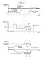
- FIG. 8 is a timing chart of a first start assist process and the second start assist process according to the embodiment 1.
- FIG. 9 is a flowchart illustrating an example (embodiment 2) of start assist control performed by the control device 50 .
- FIG. 10 is a flowchart illustrating an example of a manner determining process for the initial execution of a second start assist process according to the embodiment 2.
- FIG. 11 is a diagram illustrating an example of a map defining a relationship between a gear ratio and an increasing gradient G 2 .
- FIG. 12 is a flowchart illustrating an example of the second start assist process according to the embodiment 2.
- FIG. 13 is a timing chart of a first start assist process and the second start assist process according to the embodiment 2.
- FIG. 14 is a flowchart illustrating an example of a manner determining process for the initial execution of a second start assist process according to an embodiment 3.
- FIG. 1 is a structure diagram schematically illustrating an example of a vehicle drive system for which the control device is preferably adapted.
- a first engagement device 11 In a vehicle drive system 1 , as illustrated in FIG. 1 , a first engagement device 11 , a rotating electrical machine 3 , a transmission 4 , and an output shaft 5 are provided in a power transfer path connecting an internal combustion engine 2 to wheels 7 and are arranged in this order from the internal combustion engine 2 side. A damper may be provided between the internal combustion engine 2 and the first engagement device 11 .
- the vehicle drive system 1 may include additional elements other than those illustrated in FIG. 1 . The example of FIG.
- FIG. 1 illustrates a rotational speed detecting sensor 31 for detecting the rotational speed of the internal combustion engine 2 , a rotational speed detecting sensor 32 for detecting the rotational speed of the rotating electrical machine 3 , and a rotational speed detecting sensor 33 for detecting the rotational speed of the output shaft 5 .
- the rotating electrical machine 3 is, for example, a motor generator having an electricity generating function.
- the transmission 4 is, for example, an automatic transmission (AT).
- the transmission 4 may have any structure and may be, for example, a dual clutch transmission (DCT), a continuously variable transmission (CVT), or an automated manual transmission (AMT), etc.
- DCT dual clutch transmission
- CVT continuously variable transmission
- AMT automated manual transmission
- the first engagement device 11 includes a friction engagement element. Controlling a hydraulic pressure applied to the first engagement device 11 controls an engagement pressure of the first engagement device 11 , thus controlling a transfer torque capacity.
- the first engagement device 11 may be a wet multi-plate clutch.
- directly engaged state refers to a directly engaged state from the point of view of control.
- the “directly engaged state” does not exclude a state where there is a slight rotational speed difference (slip) between engagement members of friction engagement elements.
- disengaged state refers to a disengaged state from the point of view of control and does not exclude a state where there is a slight transfer torque capacity caused by drag between friction members.
- the vehicle drive system 1 includes a hydraulic control device 8 .
- the hydraulic control device 8 controls, in accordance with a command (hydraulic command) from a later-described control device, hydraulic pressures applied to the first engagement device 11 and the transmission 4 .
- a part or whole of the functions of the hydraulic control device 8 may be implemented by a later-described control device 50 .
- FIG. 2 is a diagram illustrating an example (embodiment 1) of a functional unit of the control device 50 .
- the control device 50 is implemented by a computer. It is noted that an illustration of the hardware structure of the control device 50 is omitted.
- the functions of the control device 50 described below may be implemented by a hardware, a software, a firmware, or a combination of these. Further, the control device 50 may be implemented by multiple control devices that work in conjunction with each other.
- the control device 50 is connected to the rotational speed detecting sensor 31 , an internal combustion engine control device 60 , the rotating electrical machine 3 , and the hydraulic control device 8 .
- This connection may be Made in any manner, including indirect connection via other control devices, direct connection, and wirelessly communicable connection.
- the control device 50 controls the rotating electrical machine 3 and the hydraulic control device 8 in conjunction with the internal combustion engine control device 60 that controls the internal combustion engine 2 .
- the internal combustion engine control device 60 determines a drive mode (e.g., an electric mode in which only the rotating electrical machine 3 is used as a power source to drive or a parallel mode in which at least the internal combustion engine 2 is used as a power source to drive) on the basis of a determined required drive force, the state of charge (SOC) of a battery etc.
- the internal combustion engine control device 60 generates a control command for the rotating electrical machine 3 and a control command for the transmission 4 on the basis of the determined drive mode, the determined required drive force, etc.
- the control device 50 controls the rotating electrical machine 3 and the hydraulic control device 8 in accordance with the control commands.
- the control device 50 controls the first engagement device 11 and the transmission 4 via the hydraulic control device 8 .
- the required drive force refers to a target value for a drive force that is applied to the wheels 7 through the output shaft 5 .
- the required drive force is typically determined in accordance with accelerator pedal operation amount (accelerator opening degree) by a driver. However, for a vehicle with autonomous drive control, the required drive force may be determined on the basis of, for example, a set speed, a relationship with vehicles ahead, etc.
- a part or whole of the functions of the control device 50 may be implemented by the internal combustion engine control device 60 , and apart, or whole of the functions of the internal combustion engine control device 60 may be implemented by the control device 50 .
- the control device 50 performs, in conjunction with the internal combustion engine control device 60 , later-described start assist control to start the internal combustion engine 2 that is at a standstill. Specifically, when the control device 50 executes a later-described first start assist process or a later-described second start assist process, cranking of the internal combustion engine 2 begins, and the internal combustion engine control device 60 performs start control for the internal combustion engine 2 by using the cranking.
- the start control performed by the internal combustion engine control device 60 includes igniting fuel in a cylinder that is in compression stroke during the cranking.
- the control device 50 includes a first start assist processing unit 51 , a second start assist processing unit 52 , and an information acquiring unit 56 .
- the first start assist processing unit 51 executes a first start assist process in synchronization with the start control performed by the internal combustion engine control device 60 .
- the first start assist process includes bringing the first engagement device 11 into slip engagement at a first engagement pressure P 1 while increasing torque generated by the rotating electrical machine 3 , in order to start the internal combustion engine 2 that is at a standstill when the first engagement device 11 is in the disengaged state.
- the second start assist processing unit 52 executes a second start assist process in synchronization with the start control performed by the internal combustion engine control device 60 .
- the second start assist process includes increasing the engagement pressure of the first engagement device 11 to a second engagement pressure P 2 higher than the first engagement pressure P 1 while increasing the torque generated by the rotating electrical machine 3 .
- the second start assist processing unit 52 determines the second engagement pressure P 2 on the basis of an increasing manner in which the rotational speed of the internal combustion engine 2 increases in association with the first start start assist process.
- the increasing manner in which the rotational speed of the internal combustion engine 2 increases can be determined on the basis of, for example, the amount of increase in the rotational speed, the rate of increase in the rotational speed (the amount of increase per time period), the peak value of the rotational speed, etc.
- the second start assist processing unit 52 determines the second engagement pressure P 2 in such a manner that the second engagement pressure P 2 is greater than the first engagement pressure P 1 and less than or equal to an upper limit P 2 max and that the second engagement pressure P 2 becomes lower as the amount of increase in the rotational speed of the internal combustion engine 2 in association with the first start start assist process becomes larger.
- the upper limit P 2 max is not an upper limit of performance of the first engagement device 11 . It is noted that the upper limit P 2 max is a value within a range where the first engagement device 11 is controlled to be in a slip engagement state, and for example, is an upper limit employable in the start assist control.
- the information acquiring unit 56 acquires various information used in the start assist control.
- the second start assist processing unit 52 executes the second start assist process at the second engagement pressure P 2 higher than the first engagement pressure P 1 .
- the transfer torque capacity of the first engagement device 11 increases with the increase in the second engagement pressure P 2 , and accordingly, the amount of reduction in output torque at the wheels 7 due to the transfer torque capacity of the first engagement device 11 increases.
- the amount of reduction in output torque at the wheels 7 is compensable by an increase in torque generated by the rotating electrical machine 3 .
- the likelihood of the amount of this reduction being uncompensated by the rotating electrical machine 3 becomes larger.
- deceleration feel may be caused. Therefore, as the second engagement pressure P 2 becomes larger, the startability of the internal combustion engine 2 increases, but the likelihood of deceleration feel being caused also increases.
- the second start assist processing unit 52 determines the second engagement pressure P 2 on the basis of the increasing manner in which the rotational speed of the internal combustion engine 2 increases in association with the first start start assist process. This allows the second engagement pressure P 2 to be optimized in accordance with the increasing manner in which the rotational speed of the internal combustion engine 2 increases in association with the first start start assist process, thus making it possible to reduce or prevent an increase in the transfer torque capacity of the first engagement device 11 that causes deceleration feel.
- control device 50 is described along with the functions of the first start assist processing unit 51 and the second start assist processing unit 52 .
- FIG. 3 is a flowchart illustrating an example (embodiment 1) of the start assist control performed by the control device 50 .
- the procedure illustrated in FIG. 3 is, for example, repeatedly performed at predetermined cycles during a vehicle operation.
- step S 302 the information acquiring unit 56 acquires the latest information used in the start assist control illustrated in FIG. 3 .
- the information includes, for example, rotational speed information from the rotational speed detecting sensor 31 and information from the internal combustion engine control device 60 (e.g., a command value for a torque generated by the rotating electrical machine 3 ).
- the first start assist in-process flag of “1.” means that the first start assist process is being executed, and the first start assist in-process flag of “0” means that the first start assist process is not being executed.
- the second start assist in-process flag of “1” means that the second start assist process is being executed, and the second start assist in-process flag of “0” means that the second start assist process is not being executed. If the determination result is “YES”, the start assist control proceeds to step S 308 ; whereas if the determination result is “NO”, the start assist control proceeds to step S 306 .
- step S 308 the first start assist processing unit 51 determines whether or not a condition for starting internal combustion engine start assist control is met.
- the condition for starting the internal combustion engine start assist control may be met, for example, when all the following conditions (1) to (3) are met. However, additional conditions may be imposed.
- An internal combustion engine start assist control request is issued from the internal combustion engine control device 60 .
- step S 310 If the determination result is “YES”, the start assist control proceeds to step S 310 ; whereas if the determination result is “NO”, the start assist control ends.
- step S 310 the first start assist processing unit 51 sets the first start assist in-process flag to “1”.
- step S 312 the first start assist processing unit 51 executes the first start assist process.
- the first start assist process includes bringing the first engagement device 11 into slip engagement at the first engagement pressure P 1 while increasing the torque generated by the rotating electrical machine 3 .
- the first start assist processing unit 51 controls the rotating electrical machine 3 on the basis of a target torque that is the sum of the command value for a generated torque commanded by the internal combustion engine control device 60 and a compensating torque for compensating the present transfer torque capacity of the first engagement device 11 , so that the target torque can be achieved.
- step S 314 the first start assist processing unit 51 stores the present internal combustion engine rotational speed on the basis of information from the rotational speed detecting sensor 31 .
- the start failure flag is set to “1” by the internal combustion engine control device 60 when the start control fails to start the internal combustion engine 2 .
- the start failure flag of “1” means that the start control by the internal combustion engine control device 60 ends in failure; whereas the start failure flag of “0” means that the start control by the internal combustion engine control device 60 does not end in failure (including an indefinite state).
- the first start assist processing unit 51 may determine whether or not the first start assist process fails to start the internal combustion engine 2 , on the basis of other information. For example, the first start assist processing unit 51 can determine whether or not the internal combustion engine 2 fails to start, on the basis of the rotational speed information from the rotational speed detecting sensor 31 . For example, when the rotational speed of the internal combustion engine 2 drops to zero after increasing synchronously with the first start assist process, the first start assist processing unit 51 may determine that the first start assist process fails to start the internal combustion engine 2 . If the determination result is “YES”, the start assist control proceeds to step S 322 ; whereas if the determination result is “NO”, the start assist control proceeds to step S 318 .
- step S 318 the first start assist processing unit 51 determines whether or not the internal combustion engine control device 60 in conjunction with the first start assist process completes the start control for the internal combustion engine 2 .
- Whether or not the internal combustion engine control device 60 completes the start control for the internal combustion engine 2 can be determined, for example, on the basis of information (e.g., a start completion flag) acquirable from the internal combustion engine control device 60 .
- whether or not the internal combustion engine control device 60 completes the start control for the internal combustion engine 2 can be determined on the basis of the rotational speed information from the rotational speed detecting sensor 31 .
- the first start assist processing unit 51 may determine that the internal combustion engine control device 60 completes the start control for the internal combustion engine 2 . If the determination result is “YES”, the start assist control proceeds to step S 320 ; whereas if the determination result is “NO”, the start assist control proceeds to step S 312 .
- step S 320 the first start assist processing unit 51 resets the first start assist in-process flag to “0”. As a result, the first start assist process ends. Accordingly, the first engagement device 11 is brought into the directly engaged state.
- step S 322 the first start assist processing unit 51 resets the first start assist in-process flag to “0” and sets the second start assist in-process flag to “1”. As a result, the first start assist process ends, and the second start assist process starts.
- step S 324 the second start assist processing unit 52 executes a process of determining an execution manner for the first execution of the second start assist process (hereinafter, sometimes referred to as a “manner determining process for the initial execution of the second start assist process”).
- a process of determining an execution manner for the first execution of the second start assist process hereinafter, sometimes referred to as a “manner determining process for the initial execution of the second start assist process”.
- step S 325 the second start assist processing unit 52 resets the start failure flag to “0”.
- step S 326 the second start assist processing unit 52 determines whether or not the present execution of the second start assist process fails to start the internal combustion engine 2 (i.e., determines whether or not the internal combustion engine control device 60 in conjunction with the present execution of the second start assist process fails to start the internal combustion engine 2 ). This determination is made in the same way as that described above for step S 316 . If the determination result is “YES”, the start assist control proceeds to step S 334 ; whereas if the determination result is “NO”, the start assist control proceeds to step S 328 .
- step S 328 the second start assist processing unit 52 determines whether or not the internal combustion engine control device 60 in conjunction with the present execution of the second start assist process completes the start control for the internal combustion engine 2 .
- the determination of whether or not the internal combustion engine control device 60 completes the start control for the internal combustion engine 2 is made in the same way as that described above for step S 318 . If the determination result is “YES”, the start assist control proceeds to step S 329 ; whereas if the determination result is “NO”, the start assist control proceeds to step S 330 .
- step S 329 the second start assist processing unit 52 resets the second start assist in-process flag to “0”. As a result, the second start assist process ends. Accordingly, the first engagement device 11 is brought into the directly engaged state.
- step S 330 the second start assist processing unit 52 executes the second start assist process in accordance with a manner for the second start assist process that has been determined by the manner determining process for the initial execution of the second start assist process (step S 324 ) or that has been determined by the manner determining process for the second or later execution of the second start assist process (step S 334 ).
- the second start assist process can be started at any timing.
- the second start assist processing unit 52 may start the second start assist process when the internal combustion engine start assist control request is reissued from the internal combustion engine control device 60 (when the internal combustion engine start assist control request is issued after the start failure flag is reset to “0”).
- a specific example of the second start assist process is described later with reference to the drawings including FIG. 6 .
- step S 332 the second start assist processing unit 52 stores the present internal combustion engine rotational speed on the basis of information from the rotational speed detecting sensor 31 .
- the second start assist processing unit 52 executes a process of determining an execution manner for the next (the second or later) execution of the second start assist process (hereinafter, sometimes referred to as a “manner determining process for the second or later execution of the second start assist process”).
- the manner determining process for the second or later execution of the second start assist process includes determining the second engagement pressure P 2 .
- the manner determining process for the second or later execution of the second start assist process determines a manner for the second start assist process that achieves startability better than the startability achieved by the manner determining process for the initial execution of the second start assist process.
- the manner determining process for the second or later execution of the second start assist process sets the second engagement pressure P 2 to the upper limit P 2 max and sets an increasing gradient G 2 to a fixed value.
- the second start assist process is executed in the manner for the second start assist process determined by the manner determining process for the initial execution of the second start assist process. Further, when the second start assist process executed in the manner for the second start assist process determined by the manner determining process for the initial execution of the second start assist process fails to start the internal combustion engine 2 , the second start assist process is executed in the manner for the second start assist process determined by the manner determining process for the second or later execution of the second start assist process.
- FIG. 4 is a flowchart illustrating an example of the manner determining process for the initial execution of the second start assist process according to the embodiment 1.
- the process illustrated in FIG. 4 is executed as a procedure in step S 324 illustrated in FIG. 3 .
- step S 400 the second start assist processing unit 52 reads stored data (refer to step S 314 ) about the internal combustion engine rotational speed that has appeared during execution of the first start assist process.
- step S 402 the second start assist processing unit 52 identifies, on the basis of the read stored data, a peak value Np (the maximum value) of the rotational speed of the internal combustion engine 2 in association with the first start assist process.
- step S 404 the second start assist processing unit 52 determines the second engagement pressure P 2 corresponding to the peak value Np identified in step S 402 .
- a map defining a relationship between the peak value Np and the second engagement pressure P 2 is prepared and stored in a storage device (not illustrated in the drawings).
- the second engagement pressure P 2 is determined to be the upper limit P 2 max .
- the second engagement pressure P 2 decreases in proportion to the peak value Np.
- the second engagement pressure P 2 is determined to be a minimum value P 2 0 .
- the example illustrated in FIG. 5 is just one example, and various modifications are possible.
- the relationship between the second engagement pressure P 2 and the peak value Np in the range from N 1 to N 2 may be nonlinear, and N 1 may be zero.
- the second engagement pressure P 2 is determined, on the basis of the peak value Np of the rotational speed of the internal combustion engine 2 in association with the first start assist process, in such a manner that the second engagement pressure P 2 becomes smaller as the peak value Np becomes larger.
- the second start assist processing unit 52 may calculate, on the basis of the peak value Np of the rotational speed of the internal combustion engine 2 in association with the first start assist process, a deviation between the peak value Np and a reference value and may determine the second engagement pressure P 2 corresponding to the calculated deviation.
- the reference value may correspond to a rotational speed that allows self-sustaining operation.
- the reference value is calibrated on the basis of, for example, tests and stored in a storage device (not illustrated in the drawings).
- the second start assist processing unit 52 determines the second engagement pressure P 2 in such a manner that the second engagement pressure P 2 becomes smaller as the deviation becomes smaller. Even in this manner, it is still true that the second start assist processing unit 52 determines the second engagement pressure P 2 in such a manner that the second engagement pressure P 2 becomes lower as the peak value Np of the rotational speed of the internal combustion engine 2 that has increased in the first start assist process becomes larger.
- the second start assist processing unit 52 may determine, on the basis of the rate of increase in the rotational speed (the amount of increase per time period) of the internal combustion engine 2 in association with the first start assist process, the second engagement pressure P 2 in such a manner that the second engagement pressure P 2 becomes smaller as the rate of increase in the rotational speed becomes larger.
- the peak value Np of the rotational speed of the internal combustion engine 2 in association with the first start assist process becomes larger as the rate of increase in the rotational speed of the internal combustion engine 2 in association with the first start assist process becomes larger. It is noted that the rate of increase in the rotational speed of the internal combustion engine 2 can be acquired by twice differentiating, with respect to time, time series of detected crank angles acquired from a crank angel sensor.
- FIG. 6 is a flowchart illustrating an example of the second start assist process according to the embodiment 1. The process illustrated in FIG. 6 is executed as a procedure in step S 330 illustrated in FIG. 3 .
- step S 600 the second start assist processing unit 52 reads the second engagement pressure P 2 that has been determined by the manner determining process for the initial execution of the second start assist process (step S 324 ) or that has been determined by the manner determining process for the second or later execution of the second start assist process (step S 334 ).
- step S 602 the second start assist processing unit 52 reads a previous value P 2 ( i ⁇ 1) of the command value for the engagement pressure of the first engagement device 11 . It is noted that in an initial processing cycle, the previous value P 2 ( i ⁇ 1) of the command value for the engagement pressure is the present value of the engagement pressure of the first engagement device 11 .
- step S 604 the second start assist processing unit 52 calculates a present value P 2 ( i ) of the command value for the engagement pressure of the first engagement device 11 .
- the second start assist processing unit 52 provides the hydraulic control device 8 with a hydraulic command having a command value of the calculated present value P 2 ( i ).
- step S 606 the second start assist processing unit 52 calculates, on the basis of the present value P 2 ( i ) of the command value for the engagement pressure of the first engagement device 11 , a torque that the rotating electrical machine 3 needs to compensate for (hereinafter, referred to as the “compensating torque”). Specifically, the second start assist processing unit 52 calculates a compensating torque for compensating the transfer torque capacity of the first engagement device 11 corresponding to the present value P 2 ( i ).
- step S 608 the second start assist processing unit 52 calculates a target torque by adding the compensating torque calculated in step S 606 to the command value for a generated torque commanded by the internal combustion engine control device 60 .
- the target torque is calculated by adding a compensating torque ⁇ Trm to a command value Tim for a generated torque commanded by the internal combustion engine control device 60 .
- a hatched region R corresponds to a region for an electric mode in which only the rotating electrical machine 3 is used as a power source to drive.
- step S 610 the second start assist processing unit 52 determines whether or not the target torque calculated in step S 608 is less than or equal to the maximum torque outputtable by the rotating electrical machine 3 . If the determination result is “YES”, the second start assist process proceeds to step S 614 ; whereas if the determination result is “NO”, the second start assist process proceeds to step S 612 .
- step S 612 the second start assist processing unit 52 corrects the target torque calculated in step S 608 to the maximum torque outputtable by the rotating electrical machine 3 .
- step S 614 the second start assist processing unit 52 controls the rotating electrical machine 3 so that the target torque can be achieved.
- the process illustrated in FIG. 6 makes it possible to increase the engagement pressure of the first engagement device 11 toward the second engagement pressure P 2 in accordance with the second engagement pressure P 2 that has been determined by the manner determining process for the initial execution of the second start assist process or that has been determined by the manner determining process for the second or later execution of the second start assist process. Further, it makes it possible to control the torque generated by the rotating electrical machine 3 so that the transfer torque capacity of the first engagement device 11 corresponding to the engagement pressure of the first engagement device 11 can be compensated.
- FIG. 8 is an explanatory diagram of the procedure illustrated in FIG. 3 and is a timing chart of the first start assist process and the second start assist process according to the embodiment 1. From the top, FIG. 8 illustrates a time series of a rotational speed, a time series of a hydraulic pressure, and a time series of a torque. As the time series of a rotational speed, the rotational speed of the internal combustion engine 2 (internal combustion engine rotational speed), the rotational speed of the rotating electrical machine 3 (motor rotational speed), and a synchronous line are illustrated. The synchronous line corresponds to a rotational speed that is obtained by multiplying the rotational speed of the output shaft 5 by a gear ratio (speed ratio) presently achieved by the transmission 4 .
- a gear ratio speed ratio
- a time series of the hydraulic command (engagement pressure) for the first engagement device 11 is illustrated in three patterns from PT 0 to PT 2 .
- the patterns from PT 0 to PT 2 differ in the second engagement pressure P 2 from each other.
- the pattern PT 0 represents a case where the second engagement pressure P 2 is determined to be P 2 0
- the pattern PT 1 represents a case where the second engagement pressure P 2 is determined to be P 2 1
- the pattern PT 2 represents a case where the second engagement pressure P 2 is determined to be P 2 2 , where P 2 0 ⁇ P 2 1 ⁇ P 2 2 .
- a time series of the torque generated by the rotating electrical machine 3 (motor torque) and a time series of the transfer torque capacity of the first engagement device 11 (SSC transfer torque) are each illustrated in three patterns.
- Each pattern corresponds to a difference (three patterns) in the second engagement pressure P 2 .
- a dotted line section represents a pattern before a correction to the maximum torque (step S 612 ) is made. It is noted that for the transfer torque capacity of the first engagement device 11 , a negative section until a time t 8 (a section used to start the internal combustion engine 2 ) is illustrated.
- the condition for starting the internal combustion engine start assist control is met (“YES” in step S 308 ), and accordingly, the first start assist process is started.
- the first start assist process increases the hydraulic command (engagement pressure) for the first engagement device 11 to the first engagement pressure P 1 and causes the rotating electrical machine 3 to generate a compensating torque for compensating the transfer torque capacity of the first engagement device 11 .
- a value P 0 is a hydraulic command for increasing responsivity.
- the internal combustion engine rotational speed increases, but is still insufficient for starting (rotational speed that allows self-sustaining operation), so that the start of the internal combustion engine 2 ends in failure (“YES” in step S 316 ).
- the second start assist process is started (step S 330 )
- the second engagement pressure P 2 is determined to be P 2 1 (step S 324 ), and the hydraulic command (engagement pressure) for the first engagement device 11 is increased so that the second engagement pressure P 2 can become equal to P 2 1 .
- the transfer torque capacity of the first engagement device 11 increases (refer to a pattern S 1 ), and the torque generated by the rotating electrical machine 3 is increased to compensate the amount of increase in the transfer torque capacity of the first engagement device 11 (refer to a pattern M 1 ).
- the second start assist process succeeds in starting the internal combustion engine 2 , and accordingly, the hydraulic command for the first engagement device 11 is temporarily reduced to a value P 4 . Accordingly, the transfer torque capacity of the first engagement device 11 is reduced, and the torque generated by the rotating electrical machine 3 is reduced in accordance with the amount of reduction in the transfer torque capacity of the first engagement device 11 .
- an engagement device (not illustrated in the drawings) inside the transmission 4 is brought into the slip engagement state.
- the rotational speed of the internal combustion engine 2 synchronizes with the rotational speed of the rotating electrical machine 3 , and the hydraulic command for the first engagement device 11 is increased to a value P 5 , so that the first engagement device 11 is brought into the directly engaged state.
- the transfer torque capacity of the first engagement device 11 increases with the increase in the second engagement pressure P 2 , and accordingly the likelihood of deceleration feel being caused increases.
- the pattern M 2 represents a torque that the rotating electrical machine 3 needs to generate to fully compensate the transfer torque capacity of the first engagement device 11 .
- an amount exceeding the maximum torque is an uncompensable torque. As the uncompensable torque becomes larger, the likelihood of deceleration feel being caused becomes larger.
- the second start assist processing unit 52 determines, on the basis of the peak value Np of the rotational speed of the internal combustion engine 2 in association with the first start start assist process, the second engagement pressure P 2 , in such a manner that the second engagement pressure P 2 becomes lower as the peak value Np becomes larger.
- the procedure illustrated in FIG. 3 increases the startability of the internal combustion engine 2 while reducing or preventing deceleration feel that is caused by an increase in the transfer torque capacity of the first engagement device 11 .
- the embodiment 2 differs from the embodiment 1 in that an increasing gradient G 2 changes in accordance with a gear ratio.
- a control device 50 B includes the first start assist processing unit 51 , a second start assist processing unit 52 B, and the information acquiring unit 56 .
- FIG. 9 is a flowchart illustrating an example (embodiment 2) of start assist control performed by the control device 50 B.
- the procedure illustrated in FIG. 9 is, for example, repeatedly executed at predetermined cycles during a vehicle operation.
- the procedure illustrated in FIG. 9 differs from the procedure illustrated in FIG. 3 in that both step S 314 and step S 332 are eliminated.
- FIG. 10 is a flowchart illustrating an example of a manner determining process for the initial execution of the second start assist process according to the embodiment 2.
- the process illustrated in FIG. 10 is executed as a procedure in step S 324 illustrated in FIG. 9 .
- step S 1000 the second start assist processing unit 52 B identifies a presently achieved gear speed (the present gear ratio of the transmission 4 ).
- the present gear ratio of the transmission 4 can be obtained on the basis of control information of the control device 50 B itself.
- the present gear ratio of the transmission 4 may be identified on the basis of information from a shift position sensor (not illustrated in the drawings).
- step S 1002 the second start assist processing unit 52 B determines the increasing gradient G 2 corresponding to the present gear ratio of the transmission 4 .
- a map defining a relationship between the present gear ratio and the increasing gradient G 2 is prepared and stored in a storage device (not illustrated in the drawings).
- the gear ratio achievable by the transmission 4 has a range from ⁇ 0 to ⁇ max , and the increasing gradient G 2 decreases in proportion to the gear ratio.
- the example illustrated in FIG. 11 is just one example, and various modifications are possible.
- the increasing gradient G 2 may increase non-linearly with an increase in the gear ratio.
- the increasing gradient G 2 is determined, on the basis of the present gear ratio of the transmission 4 , in such a manner that the increasing gradient G 2 becomes smaller as the gear ratio becomes larger.
- FIG. 12 is a flowchart illustrating an example of the second start assist process according to the embodiment 2. The process illustrated in FIG. 12 is executed as a procedure in step S 330 illustrated in FIG. 9 .
- the process illustrated in FIG. 12 differs from the process illustrated in FIG. 6 in that steps S 600 to S 604 are replaced with steps S 1200 to S 1204 .
- the following description is focused on the difference from the process illustrated in FIG. 6 .
- step S 1200 the second start assist processing unit 52 B reads an increasing gradient G 2 that has been determined by the manner determining process for the initial execution of the second start assist process (step S 324 ) or that has been determined by the manner determining process for the second or later execution of the second start assist process (step S 334 ). Further, the second start assist processing unit 52 B reads the second engagement pressure P 2 .
- the second engagement pressure P 2 is a predetermined fixed value (>the first engagement pressure P 1 ).
- step S 1202 the second start assist processing unit 52 B reads a previous value P 2 ( i ⁇ 1) of the command value for the engagement pressure of the first engagement device 11 .
- step S 1204 the second start assist processing unit 52 B calculates a present value P 2 ( i ) of the command value for the engagement pressure of the first engagement device 11 .
- the second start assist processing unit 52 B provides the hydraulic control device 8 with a hydraulic command having a command value of the calculated present value P 2 ( i ).
- the process illustrated in FIG. 12 makes it possible to increase the engagement pressure of the first engagement device 11 toward the second engagement pressure P 2 in accordance with the increasing gradient G 2 that has been determined by the manner determining process for the initial execution of the second start assist process or that has been determined by the manner determining process for the second or later execution of the second start assist process. Further, it makes it possible to control the torque generated by the rotating electrical machine 3 so that the transfer torque capacity of the first engagement device 11 corresponding to the engagement pressure of the first engagement device 11 can be compensated.
- FIG. 13 is an explanatory diagram of the procedure illustrated in FIG. 9 and is a timing chart of the first start assist process and the second start assist process according to the embodiment 2. From the top, FIG. 13 illustrates a time series of a rotational speed, a time series of a hydraulic pressure, and a time series of a torque. As the time series of a rotational speed, the rotational speed of the internal combustion engine 2 (internal combustion engine rotational speed), the rotational speed of the rotating electrical machine 3 (motor rotational speed), and a synchronous line are illustrated. As the time series of a hydraulic pressure, a time series of the hydraulic command (engagement pressure) for the first engagement device 11 is illustrated in three patterns from PT 0 to PT 2 .
- the patterns from PT 0 to PT 2 differ in the increasing gradient G 2 from each other.
- the pattern PT 0 represents a case where the increasing gradient G 2 is determined to be G 2 0
- the pattern represents a case where the increasing gradient G 2 is determined to be G 2 1
- the pattern PT 2 represents a case where the increasing gradient G 2 is determined to be G 2 2 , where G 2 0 ⁇ G 2 1 ⁇ G 2 2 .
- As the time series of a torque a time series of the torque generated by the rotating electrical machine 3 (motor torque) and a time series of the transfer torque capacity of the first engagement device 11 (SSC transfer torque) are each illustrated in three patterns. Each pattern corresponds to a difference (three patterns) in the second engagement pressure P 2 .
- a dotted line section represents a pattern before a correction to the maximum torque (step S 612 ) is made. It is noted that for the transfer torque capacity of the first engagement device 11 , a negative section until a time t 8 (a section used to start the internal combustion engine 2 ) is illustrated.
- the second start assist process is started (step S 330 ).
- the increasing gradient G 2 is determined to be G 2 1 (step S 324 ), and the hydraulic command (engagement pressure) for the first engagement device 11 is increased toward the second engagement pressure P 2 at the increasing gradient G 2 1 (a pattern PT 1 ).
- the transfer torque capacity of the first engagement device 11 increases at an increasing gradient corresponding to the increasing gradient G 2 1 (refer to a pattern S 1 ), so that the torque generated by the rotating electrical machine 3 is increased at an increasing gradient corresponding to the increasing gradient G 2 1 (refer to a pattern M 1 ).
- a torque that needs to be generated to fully compensate the transfer torque capacity of the first engagement device 11 corresponding to the second engagement pressure P 2 exceeds the maximum torque generatable by the rotating electrical machine 3 . Therefore, in the example illustrated in FIG. 13 , at a time t 3 , a target torque for the rotating electrical machine 3 exceeds the maximum torque, and the target torque is corrected to the maximum torque (refer to step S 612 ). Specifically, in the example illustrated in FIG. 13 , when the increasing gradient G 2 is equal to G 2 1 , the pattern M 1 represents a torque that the rotating electrical machine 3 needs to generate to fully compensate the transfer torque capacity of the first engagement device 11 .
- the torque uncompensated by the rotating electrical machine 3 affects an output that is transferred to the output shaft 5 (and the wheels 7 ) through the transmission 4 .
- the present gear ratio of the transmission 4 becomes larger, the amount of reduction in output torque at the wheels 7 due to the torque uncompensated by the rotating electrical machine 3 (a torque shortfall) becomes larger.
- the present gear ratio of the transmission 4 becomes larger, the likelihood of deceleration feel being caused due to the torque uncompensated by the rotating electrical machine 3 becomes larger.
- the second start assist processing unit 52 B determines, on the basis of the present gear ratio of the transmission 4 , the increasing gradient G 2 in such a manner that the increasing gradient G 2 becomes smaller as the gear ratio becomes larger. This allows the increasing gradient G 2 to be small when the gear ratio is relatively large.
- the transfer torque capacity of the first engagement device 11 corresponding to the second engagement pressure P 2 is uncompensated by the torque generated by the rotating electrical machine 3 , the increasing gradient of the transfer torque capacity of the first engagement device 11 is reduced so that deceleration feel can be reduced or prevented.
- the procedure illustrated in FIG. 9 ensures a good startability of the internal combustion engine 2 while reducing or preventing deceleration feel.
- the second start assist processing unit 52 B may determine the second engagement pressure P 2 in such a manner that the second engagement pressure P 2 becomes lower as the peak value of the rotational speed of the internal combustion engine 2 that has increased in the first start assist process becomes larger while determining the increasing gradient G 2 in such a manner that the increasing gradient G 2 becomes smaller as the gear ratio presently achieved by the transmission 4 becomes larger.
- the embodiment 3 differs from the embodiment 1 and the embodiment 2 mainly in the manner determining process for the initial execution of the second start assist process. The following description is focused on the difference.
- a control device 50 C includes the first start assist processing unit 51 , a second start assist processing unit 52 C, and the information acquiring unit 56 .
- FIG. 14 is a flowchart illustrating an example of a manner determining process for the initial execution of the second start assist process according to the embodiment 3.
- the start assist control illustrated in FIG. 3 is performed, and a procedure illustrated in FIG. 14 instead of the procedure illustrated in FIG. 4 is executed as the process of step S 324 illustrated in FIG. 3 .
- the command value for a generated torque commanded by the internal combustion engine control device 60 or the present value of a target torque for the rotating electrical machine 3 can be used as the torque Trm presently generated by the rotating electrical machine 3 .
- step S 1402 the second start assist processing unit 52 C determines whether the extra amount ⁇ Trm 1 calculated in step S 1400 is greater than a maximum compensating torque ⁇ Trm MAX by a predetermined margin ⁇ or more.
- the maximum compensating torque ⁇ Trm MAX is a transfer torque capacity of the first engagement device 11 corresponding to when the second engagement pressure P 2 is equal to the upper limit P 2 max .
- the predetermined margin ⁇ is predetermined, for example, so that a possible increase (acceleration request) in the required drive force during execution of the second start assist process can be achieved by an increase in the torque generated by the rotating electrical machine 3 . If the determination result is “YES”, the process proceeds to step S 1404 ; whereas if the determination result is “NO”, the process proceeds to step S 1406 .
- step S 1404 the second start assist processing unit 52 C determines the second engagement pressure P 2 to be the upper limit P 2 max .
- the second start assist processing unit 52 C can determine the increasing gradient G 2 to be any value.
- the second start assist processing unit 52 C may determine the increasing gradient G 2 to be an upper limit G 2 max .
- step S 1406 the second start assist processing unit 52 C determines the second engagement pressure P 2 on the basis of the peak value Np of the rotational speed of the internal combustion engine 2 in association with the first start assist process.
- the second start assist processing unit 52 C can determine the increasing gradient G 2 to be any value.
- the second start assist processing unit 52 C may determine the increasing gradient G 2 to be the upper limit G 2 max .
- step S 1408 the second start assist processing unit 52 C calculates, on the basis of the second engagement pressure P 2 determined in step S 1402 , a compensating amount (compensating torque) ⁇ Trm of a torque that the rotating electrical machine 3 needs to generate to fully compensate the transfer torque capacity of the first engagement device 11 corresponding to the second engagement pressure P 2 .
- step S 1410 a determination is made whether or not the extra amount ⁇ Trm 1 calculated in step S 1400 is greater than or equal to the compensating torque ⁇ Trm calculated in step S 1408 . If the determination result is “YES”, the process ends; whereas the determination result is “NO”, the process proceeds to step S 1412 .
- step S 1412 the second start assist processing unit 52 C determines the increasing gradient G 2 on the basis of the present gear ratio of the transmission 4 . At this time, the second start assist processing unit 52 C corrects the increasing gradient G 2 determined in step S 1406 to the increasing gradient G 2 determined in step S 1412 .
- step S 330 illustrated in FIG. 3 .
- the procedure in step S 330 is the same as that already described above with reference to FIG. 6 .
- the increasing gradient G 2 determined in the process illustrated in FIG. 14 is used instead of a fixed value.
- the process illustrated in FIG. 14 determines the second engagement pressure P 2 to be the upper limit, thereby maximizing the startability of the internal combustion engine 2 .
- the extra amount ⁇ Trm 1 of the rotating electrical machine 3 is not relatively large, it makes it possible to reduce or prevent deceleration feel while increasing the startability of the internal combustion engine 2 .
- the second engagement pressure P 2 is set to a lower value.
- the increasing gradient G 2 is a constant gradient that causes the engagement pressure of the first engagement device 11 to increase linearly with respect to time, but the increasing gradient G 2 may be defined by multiple gradient values that cause the engagement pressure of the first engagement device 11 to increase non-linearly with respect to time.
- a control device ( 50 , 50 C) is adapted for a vehicle drive system ( 1 ) in which a first engagement device ( 11 ) and a rotating electrical machine ( 3 ) are provided in a power transfer path connecting an internal combustion engine ( 2 ) to wheels ( 7 ), performs start assist control for the internal combustion engine, and includes: a first start assist processing unit ( 51 ) that executes, when the first engagement device ( 11 ) is in a disengaged state, a first start assist process that brings the first engagement device ( 11 ) into slip engagement at a first engagement pressure (P 1 ) while increasing a torque generated by the rotating electrical machine ( 3 ); and a second start assist processing unit ( 52 , 52 C) that executes, when the first start assist process fails to start the internal combustion engine ( 2 ), a second start assist process that increases an engagement pressure of the first engagement device ( 11 ) to a second engagement pressure (P 2 ) higher than the first engagement pressure (P 1 ) while increasing the torque generated by the rotating electrical machine ( 3 ), wherein the
- the first start assist process when the first engagement device ( 11 ) is in a disengaged state, the first start assist process can be executed so that the first engagement device ( 11 ) is brought into slip engagement at the first engagement pressure (P 1 ), and when the first start assist process fails to start the internal combustion engine ( 2 ), the second start assist process can be executed.
- the second start assist process increases the engagement pressure of the first engagement device ( 11 ) to the second engagement pressure (P 2 ) higher than the first engagement pressure (R 1 ) while increasing the torque generated by the rotating electrical machine ( 3 ).
- the second start assist process can increase the startability of the internal combustion engine ( 2 ).
- the second engagement pressure (P 2 ) used in the second start assist process is determined based on the rotational speed of the internal combustion engine ( 2 ) in the first start assist process. This reduces the likelihood of the second engagement pressure (P 2 ) becoming unnecessarily large, thus reducing or preventing an increase in the transfer torque capacity of the first engagement device ( 11 ) that causes deceleration feel. Specifically, although the likelihood of deceleration feel being caused increases with an increase in the second engagement pressure (P 2 ) because the transfer torque capacity of the first engagement device ( 11 ) corresponding to the second engagement pressure (P 2 ) may be uncompensated by the torque generated by the rotating electrical machine ( 3 ), the structure described in (1) reduces the likelihood.
- the second start assist processing unit ( 52 , 52 C) determines the second engagement pressure (P 2 ) in such a manner that the second engagement pressure (P 2 ) becomes lower as the peak value of the rotational speed of the internal combustion engine ( 2 ) that has increased in the first start assist process becomes larger.
- the structure described in (2) determines the second engagement pressure (P 2 ) used in the second start assist process on the basis of the peak value of the rotational speed of the internal combustion engine ( 2 ) that has increased in the first start assist process, thus increasing the likelihood of the second engagement pressure (P 2 ) being determined to be a minimum engagement pressure required to start the internal combustion engine ( 2 ). This is because the peak value of the rotational speed of the internal combustion engine ( 2 ) is highly correlated with the startability of the internal combustion engine ( 2 ).
- increasing the torque generated by the rotating electrical machine ( 3 ) in the second start assist process includes controlling the rotating electrical machine ( 3 ) so that a target torque is generated, and the second start assist processing unit ( 52 , 52 C) determines the target torque on the basis of the transfer torque capacity of the first engagement device ( 11 ) corresponding to the second engagement pressure (P 2 ).
- the structure described in (3) allows the transfer torque capacity of the first engagement device ( 11 ) corresponding to the second engagement pressure (P 2 ) to be compensated by the torque generated by the rotating electrical machine ( 3 ) during execution of the second start assist process.
- a transmission ( 4 ) is provided between the rotating electrical machine ( 3 ) and the wheels ( 7 ) in the vehicle drive system ( 1 ), increasing the engagement pressure of the first engagement device ( 11 ) to the second engagement pressure (P 2 ) in the second start assist process includes increasing the engagement pressure of the first engagement device ( 11 ) toward the second engagement pressure (P 2 ) at a predetermined increasing gradient (G 2 ), and when the target torque exceeds a maximum torque generatable by the rotating electrical machine ( 3 ), the second start assist processing unit ( 52 , 52 C) determines the increasing gradient (G 2 ) on the basis of a gear ratio presently achieved by the transmission ( 4 ) in such a manner that the increasing gradient (G 2 ) becomes smaller as the gear ratio becomes larger.
- the structure described in (4) reduces or prevents inconvenience caused when the target torque exceeds the maximum torque generatable by the rotating electrical machine ( 3 ) (deceleration feel caused when the transfer torque capacity of the first engagement device ( 11 ) corresponding to the second engagement pressure (P 2 ) is uncompensated by the torque generated by the rotating electrical machine ( 3 )) in the structure in which the transfer torque capacity of the first engagement device ( 11 ) corresponding to the second engagement pressure (P 2 ) is compensated by the torque generated by the rotating electrical machine ( 3 ).
- the amount of torque uncompensated by the torque generated by the rotating electrical machine ( 3 ) is transmitted to the wheels in accordance with the gear ratio presently achieved by the transmission ( 4 ).
- the likelihood of deceleration feel being caused thus increases with an increase in the gear ratio because a torque shortfall is amplified and then transferred to the wheels.
- the structure described in (4) can reduce the likelihood.
- a control device ( 50 B) is adapted for a vehicle drive system ( 1 ) in which a first engagement device ( 11 ), a rotating electrical machine ( 3 ), and a transmission ( 4 ) are provided in a power transfer path connecting an internal combustion engine ( 2 ) to wheels ( 7 ), performs start assist control for the internal combustion engine ( 2 ), and includes: a first start assist processing unit ( 51 ) that executes, when the first engagement device ( 11 ) is in a disengaged state, a first start assist process that brings the first engagement device ( 11 ) into slip engagement at a first engagement pressure (P 1 ) while increasing a torque generated by the rotating electrical machine ( 3 ); and a second start assist processing unit ( 52 B) that increases, when the first start assist process fails to start the internal combustion engine ( 2 ), an engagement pressure of the first engagement device ( 11 ) toward a second engagement pressure (P 2 ) higher than the first engagement pressure (P 1 ) at a predetermined increasing gradient (G 2 ) while increasing the torque generated by the rotating electrical machine
- the first start assist process when the first engagement device ( 11 ) is in a disengaged state, the first start assist process can be executed so that the first engagement device ( 11 ) is brought into slip engagement at the first engagement pressure (P 1 ), and when the first start assist process fails to start the internal combustion engine ( 2 ), the second start assist process can be executed.
- the second start assist process increases the engagement pressure of the first engagement device ( 11 ) to the second engagement pressure (P 2 ) higher than the first engagement pressure (P 1 ) while increasing the torque generated by the rotating electrical machine ( 3 ).
- the second start assist process increases the startability of the internal combustion engine ( 2 ).
- the increasing gradient (G 2 ) toward the second engagement pressure (P 2 ) used in the second start assist process is determined on the basis of the gear ratio presently achieved by the transmission ( 4 ) in such a manner that the increasing gradient (G 2 ) becomes smaller as the gear ratio becomes larger. This reduces or prevents an increase in the transfer torque capacity of the first engagement device ( 11 ) at an increasing gradient that causes deceleration feel.
- the transfer torque capacity of the first engagement device ( 11 ) corresponding to the second engagement pressure (P 2 ) is compensable by the torque generated by the rotating electrical machine ( 3 ), but, for example, when the target torque exceeds the maximum torque generatable by the rotating electrical machine ( 3 ), the transfer torque capacity of the first engagement device ( 11 ) corresponding to the second engagement pressure (P 2 ) may be uncompensated by the torque generated by the rotating electrical machine ( 3 ), and accordingly, deceleration feel may be caused.
- the likelihood of deceleration feel being caused increases with an increase in the gear ratio because a torque shortfall is amplified and then transferred to the wheels.
- the increasing gradient (G 2 ) toward the second engagement pressure (P 2 ) becomes smaller as the gear ratio becomes larger.
Abstract
Description
- Patent Document 1: Japanese Patent Application Publication No. 2007-99141 (JP 2007-99141 A)
P2(i)=P2(i−1)+G2×ΔT,
where G2 refers to an increasing gradient and is a fixed value. AT corresponds to a processing cycle. If P2(i) is greater than or equal to the second engagement pressure P2, P2(i) is set to the second engagement pressure P2. The second start assist processing
P2(i)=P2(i−1)+G2×ΔT,
where G2 refers to an increasing gradient and is set to the value read in step S1200. ΔT corresponds to a processing cycle. If P2(i) is greater than or equal to the second engagement pressure P2, P2(i) is set to the second engagement pressure P2. The second start assist processing unit 52B provides the
-
- 1 VEHICLE DRIVE SYSTEM
- 2 INTERNAL COMBUSTION ENGINE
- 3 ROTATING ELECTRICAL MACHINE
- 4 TRANSMISSION
- 5 OUTPUT SHAFT
- 7 WHEEL
- 8 HYDRAULIC CONTROL DEVICE
- 11 FIRST ENGAGEMENT DEVICE
- 21 SECOND ENGAGEMENT DEVICE
- 31 to 33 ROTATIONAL SPEED DETECTING SENSOR
- 50, 50B, 50C CONTROL DEVICE
- 51 FIRST START ASSIST PROCESSING UNIT
- 52, 52B, 52C SECOND START ASSIST PROCESSING UNIT
- 56 INFORMATION ACQUIRING UNIT
- 60 INTERNAL COMBUSTION ENGINE CONTROL DEVICE
Claims (7)
Applications Claiming Priority (3)
| Application Number | Priority Date | Filing Date | Title |
|---|---|---|---|
| JP2015067592 | 2015-03-27 | ||
| JP2015-067592 | 2015-03-27 | ||
| PCT/JP2016/058812 WO2016158521A1 (en) | 2015-03-27 | 2016-03-18 | Control device |
Publications (2)
| Publication Number | Publication Date |
|---|---|
| US20180009308A1 US20180009308A1 (en) | 2018-01-11 |
| US10363807B2 true US10363807B2 (en) | 2019-07-30 |
Family
ID=57006142
Family Applications (1)
| Application Number | Title | Priority Date | Filing Date |
|---|---|---|---|
| US15/547,678 Active 2036-10-12 US10363807B2 (en) | 2015-03-27 | 2016-03-18 | Control device |
Country Status (5)
| Country | Link |
|---|---|
| US (1) | US10363807B2 (en) |
| JP (1) | JP6365766B2 (en) |
| CN (1) | CN107428327B (en) |
| DE (1) | DE112016000225T5 (en) |
| WO (1) | WO2016158521A1 (en) |
Citations (9)
| Publication number | Priority date | Publication date | Assignee | Title |
|---|---|---|---|---|
| US20070080005A1 (en) * | 2005-10-06 | 2007-04-12 | Nissan Motor Co., Ltd. | Hybrid vehicle drive control system |
| JP2011195119A (en) | 2010-03-23 | 2011-10-06 | Toyota Motor Corp | Clutch device for hybrid vehicle |
| US20120115676A1 (en) * | 2010-11-04 | 2012-05-10 | Zf Friedrichshafen Ag | Method for controlling a hybrid drive train of a vehicle |
| JP2013208970A (en) | 2012-03-30 | 2013-10-10 | Aisin Aw Co Ltd | Control device |
| US20130296111A1 (en) * | 2012-05-07 | 2013-11-07 | Ford Global Technologies, Llc | Engine restart torque spike management system for a hybrid vehicle |
| US20150006063A1 (en) * | 2012-03-30 | 2015-01-01 | Aisin Aw Co., Ltd. | Control device |
| JP2015020702A (en) | 2013-07-23 | 2015-02-02 | 日産自動車株式会社 | Start control device of internal combustion engine and start control method |
| US20150266468A1 (en) * | 2014-03-19 | 2015-09-24 | Hyundai Motor Company | Hydraulic pressure instruction-learning apparatus for hybrid vehicle and method using the same |
| US20150307085A1 (en) * | 2013-01-21 | 2015-10-29 | Toyota Jidosha Kabushiki Kaisha | Control apparatus for a vehicle |
Family Cites Families (2)
| Publication number | Priority date | Publication date | Assignee | Title |
|---|---|---|---|---|
| FR2965779B1 (en) * | 2010-10-11 | 2013-06-14 | Peugeot Citroen Automobiles Sa | METHOD FOR CONTROLLING A STARTING OF A VEHICLE EQUIPPED WITH A SYSTEM FOR STARTING UP AN ENGINE |
| DE112013000310B4 (en) * | 2012-02-24 | 2021-09-16 | Aisin Aw Co., Ltd. | Control device |
-
2016
- 2016-03-18 JP JP2017509581A patent/JP6365766B2/en active Active
- 2016-03-18 WO PCT/JP2016/058812 patent/WO2016158521A1/en active Application Filing
- 2016-03-18 DE DE112016000225.4T patent/DE112016000225T5/en active Pending
- 2016-03-18 US US15/547,678 patent/US10363807B2/en active Active
- 2016-03-18 CN CN201680015295.7A patent/CN107428327B/en active Active
Patent Citations (10)
| Publication number | Priority date | Publication date | Assignee | Title |
|---|---|---|---|---|
| US20070080005A1 (en) * | 2005-10-06 | 2007-04-12 | Nissan Motor Co., Ltd. | Hybrid vehicle drive control system |
| JP2007099141A (en) | 2005-10-06 | 2007-04-19 | Nissan Motor Co Ltd | Engine start controller for hybrid vehicle |
| JP2011195119A (en) | 2010-03-23 | 2011-10-06 | Toyota Motor Corp | Clutch device for hybrid vehicle |
| US20120115676A1 (en) * | 2010-11-04 | 2012-05-10 | Zf Friedrichshafen Ag | Method for controlling a hybrid drive train of a vehicle |
| JP2013208970A (en) | 2012-03-30 | 2013-10-10 | Aisin Aw Co Ltd | Control device |
| US20150006063A1 (en) * | 2012-03-30 | 2015-01-01 | Aisin Aw Co., Ltd. | Control device |
| US20130296111A1 (en) * | 2012-05-07 | 2013-11-07 | Ford Global Technologies, Llc | Engine restart torque spike management system for a hybrid vehicle |
| US20150307085A1 (en) * | 2013-01-21 | 2015-10-29 | Toyota Jidosha Kabushiki Kaisha | Control apparatus for a vehicle |
| JP2015020702A (en) | 2013-07-23 | 2015-02-02 | 日産自動車株式会社 | Start control device of internal combustion engine and start control method |
| US20150266468A1 (en) * | 2014-03-19 | 2015-09-24 | Hyundai Motor Company | Hydraulic pressure instruction-learning apparatus for hybrid vehicle and method using the same |
Non-Patent Citations (1)
| Title |
|---|
| Jun. 7, 2016 International Search Report issued in Patent Application No. PCT/JP2016/058812. |
Also Published As
| Publication number | Publication date |
|---|---|
| US20180009308A1 (en) | 2018-01-11 |
| JP6365766B2 (en) | 2018-08-01 |
| DE112016000225T5 (en) | 2017-09-28 |
| WO2016158521A1 (en) | 2016-10-06 |
| CN107428327A (en) | 2017-12-01 |
| CN107428327B (en) | 2019-10-08 |
| JPWO2016158521A1 (en) | 2017-10-12 |
Similar Documents
| Publication | Publication Date | Title |
|---|---|---|
| CN105365807B (en) | Method and system for starting an engine | |
| US10065626B2 (en) | Feed forward and feedback adjustment of motor torque during clutch engagement | |
| US9358974B2 (en) | Method and system for adjusting hybrid vehicle driveline torque | |
| US8712613B2 (en) | Control device | |
| US8430790B2 (en) | Power transmission controlling apparatus | |
| EP3072725B1 (en) | Drive system for hybrid vehicle | |
| EP3179125B1 (en) | Vehicle control device, and vehicle control method | |
| CN104773156B (en) | System and method for driveline torque control | |
| JP6090455B2 (en) | Vehicle control device | |
| US10128784B2 (en) | Alternator charging based on marginal fuel cost | |
| JP6805635B2 (en) | Drive control device for hybrid vehicles | |
| US9393950B2 (en) | Methods and systems for restarting an engine | |
| JP6303422B2 (en) | Control device for hybrid vehicle | |
| JP5556576B2 (en) | Control device for hybrid vehicle | |
| US10363807B2 (en) | Control device | |
| JP6939036B2 (en) | Hybrid vehicle drive controller | |
| JP6812704B2 (en) | Drive control device for hybrid vehicles | |
| KR101198661B1 (en) | Control Method for Compensating Engine Knocking Using Integrated Hybrid Controller | |
| US9643614B2 (en) | Slip and energy based clutch protection | |
| JP6183169B2 (en) | Control device for hybrid vehicle | |
| JP5672306B2 (en) | Vehicle control system | |
| JP6413834B2 (en) | Drive control device | |
| JP2018075944A (en) | Vehicular control apparatus |
Legal Events
| Date | Code | Title | Description |
|---|---|---|---|
| AS | Assignment |
Owner name: AISIN AW CO., LTD., JAPAN Free format text: ASSIGNMENT OF ASSIGNORS INTEREST;ASSIGNORS:KOBAYASHI, HIROKAZU;YOSHIDA, TAKASHI;TSUDA, KOHEI;REEL/FRAME:043146/0890 Effective date: 20170508 |
|
| STPP | Information on status: patent application and granting procedure in general |
Free format text: DOCKETED NEW CASE - READY FOR EXAMINATION |
|
| STPP | Information on status: patent application and granting procedure in general |
Free format text: NOTICE OF ALLOWANCE MAILED -- APPLICATION RECEIVED IN OFFICE OF PUBLICATIONS |
|
| STPP | Information on status: patent application and granting procedure in general |
Free format text: PUBLICATIONS -- ISSUE FEE PAYMENT VERIFIED |
|
| STCF | Information on status: patent grant |
Free format text: PATENTED CASE |
|
| MAFP | Maintenance fee payment |
Free format text: PAYMENT OF MAINTENANCE FEE, 4TH YEAR, LARGE ENTITY (ORIGINAL EVENT CODE: M1551); ENTITY STATUS OF PATENT OWNER: LARGE ENTITY Year of fee payment: 4 |