WO2013121950A1 - エアバッグ装置 - Google Patents
エアバッグ装置 Download PDFInfo
- Publication number
- WO2013121950A1 WO2013121950A1 PCT/JP2013/052720 JP2013052720W WO2013121950A1 WO 2013121950 A1 WO2013121950 A1 WO 2013121950A1 JP 2013052720 W JP2013052720 W JP 2013052720W WO 2013121950 A1 WO2013121950 A1 WO 2013121950A1
- Authority
- WO
- WIPO (PCT)
- Prior art keywords
- airbag
- exhaust state
- occupant
- exhaust
- switching member
- Prior art date
- Legal status (The legal status is an assumption and is not a legal conclusion. Google has not performed a legal analysis and makes no representation as to the accuracy of the status listed.)
- Ceased
Links
Images


Classifications
-
- B—PERFORMING OPERATIONS; TRANSPORTING
- B60—VEHICLES IN GENERAL
- B60R—VEHICLES, VEHICLE FITTINGS, OR VEHICLE PARTS, NOT OTHERWISE PROVIDED FOR
- B60R21/00—Arrangements or fittings on vehicles for protecting or preventing injuries to occupants or pedestrians in case of accidents or other traffic risks
- B60R21/02—Occupant safety arrangements or fittings, e.g. crash pads
- B60R21/16—Inflatable occupant restraints or confinements designed to inflate upon impact or impending impact, e.g. air bags
- B60R21/26—Inflatable occupant restraints or confinements designed to inflate upon impact or impending impact, e.g. air bags characterised by the inflation fluid source or means to control inflation fluid flow
-
- B—PERFORMING OPERATIONS; TRANSPORTING
- B60—VEHICLES IN GENERAL
- B60R—VEHICLES, VEHICLE FITTINGS, OR VEHICLE PARTS, NOT OTHERWISE PROVIDED FOR
- B60R21/00—Arrangements or fittings on vehicles for protecting or preventing injuries to occupants or pedestrians in case of accidents or other traffic risks
- B60R21/02—Occupant safety arrangements or fittings, e.g. crash pads
- B60R21/16—Inflatable occupant restraints or confinements designed to inflate upon impact or impending impact, e.g. air bags
- B60R21/20—Arrangements for storing inflatable members in their non-use or deflated condition; Arrangement or mounting of air bag modules or components
- B60R21/205—Arrangements for storing inflatable members in their non-use or deflated condition; Arrangement or mounting of air bag modules or components in dashboards
-
- B—PERFORMING OPERATIONS; TRANSPORTING
- B60—VEHICLES IN GENERAL
- B60R—VEHICLES, VEHICLE FITTINGS, OR VEHICLE PARTS, NOT OTHERWISE PROVIDED FOR
- B60R21/00—Arrangements or fittings on vehicles for protecting or preventing injuries to occupants or pedestrians in case of accidents or other traffic risks
- B60R21/02—Occupant safety arrangements or fittings, e.g. crash pads
- B60R21/16—Inflatable occupant restraints or confinements designed to inflate upon impact or impending impact, e.g. air bags
- B60R21/23—Inflatable members
- B60R21/239—Inflatable members characterised by their venting means
-
- B—PERFORMING OPERATIONS; TRANSPORTING
- B60—VEHICLES IN GENERAL
- B60R—VEHICLES, VEHICLE FITTINGS, OR VEHICLE PARTS, NOT OTHERWISE PROVIDED FOR
- B60R21/00—Arrangements or fittings on vehicles for protecting or preventing injuries to occupants or pedestrians in case of accidents or other traffic risks
- B60R21/02—Occupant safety arrangements or fittings, e.g. crash pads
- B60R21/16—Inflatable occupant restraints or confinements designed to inflate upon impact or impending impact, e.g. air bags
- B60R21/26—Inflatable occupant restraints or confinements designed to inflate upon impact or impending impact, e.g. air bags characterised by the inflation fluid source or means to control inflation fluid flow
- B60R21/276—Inflatable occupant restraints or confinements designed to inflate upon impact or impending impact, e.g. air bags characterised by the inflation fluid source or means to control inflation fluid flow with means to vent the inflation fluid source, e.g. in case of overpressure
-
- B—PERFORMING OPERATIONS; TRANSPORTING
- B60—VEHICLES IN GENERAL
- B60R—VEHICLES, VEHICLE FITTINGS, OR VEHICLE PARTS, NOT OTHERWISE PROVIDED FOR
- B60R21/00—Arrangements or fittings on vehicles for protecting or preventing injuries to occupants or pedestrians in case of accidents or other traffic risks
- B60R21/02—Occupant safety arrangements or fittings, e.g. crash pads
- B60R21/16—Inflatable occupant restraints or confinements designed to inflate upon impact or impending impact, e.g. air bags
- B60R21/23—Inflatable members
- B60R21/231—Inflatable members characterised by their shape, construction or spatial configuration
- B60R21/2334—Expansion control features
- B60R21/2338—Tethers
- B60R2021/23382—Internal tether means
Definitions
- the present invention relates to an airbag device for protecting a vehicle occupant.
- Patent Document 1 discloses an airbag having a regulation means for regulating gas outflow from a vent hole.
- the restricting means includes a constricting member capable of confining the vent hole, and a connecting member provided so as to connect the constricting member and the occupant-facing surface of the airbag.
- the binding member is pulled through the connecting member to close the vent hole.
- the binding member is loosened and the vent hole is opened.
- Patent Document 2 As another conventional technique related to this case.
- Patent Document 1 Even in the technology disclosed in Patent Document 1, when the occupant is in an irregular posture, the occupant-facing surface and the occupant are in contact with each other before inflating, and the bent member is loosened and the vent hole is opened. It is expected that the state will be maintained to some extent. In this case, gas is discharged from the vent hole, and thereby, the airbag is suppressed to some extent from inflating rapidly.
- an appropriate gas discharge rate for gradually receiving the impact of the occupant after the airbag is inflated is different from an appropriate gas discharge rate as a countermeasure when the occupant is in an irregular posture.
- the gas is gradually discharged.
- the gas is rapidly discharged in order to prevent the airbag from hitting the occupant with a large force.
- the gas discharge speed is set so that the gas is gradually discharged assuming the former case. For this reason, even when the occupant is in an irregular posture, the gas is only gradually discharged, and thus the airbag may suddenly inflate.
- the present invention can discharge gas as quickly as possible when the occupant is in the non-regular posture state, and sudden discharge of gas when receiving the occupant in the normal posture state after inflation of the airbag.
- the purpose is to suppress.
- an airbag apparatus includes an airbag body having a gas supply port, an inflator for supplying gas into the airbag body through the gas supply port, and the airbag body.
- An exhaust state that is switched to a non-exhaust state that suppresses exhaust of the gas in the airbag body from an exhaust state that allows the gas in the airbag body to be exhausted when being drawn into the airbag body
- a switching member, and a connecting member that connects the exhaust state switching member and a part of the inner peripheral portion of the airbag main body, the disposition position of the exhaust state switching member, and the inner peripheral portion of the airbag main body
- the connecting position of the connecting member with respect to the connecting member and the passing line of the connecting member are the inflated forms of the airbag body, and the airbag body is in a normal posture state. It is provided in a portion avoiding the contact portion between the occupant when receiving the.
- a 2nd aspect is an airbag apparatus concerning a 1st aspect, Comprising: The arrangement
- the passage line is provided in a portion of the inflated form of the airbag body that avoids a portion that deforms when the airbag body receives an occupant in a normal posture state.
- a third aspect is an airbag apparatus according to the first or second aspect, wherein the exhaust state switching member is disposed, the connection position of the connection member with respect to the inner periphery of the airbag body,
- the connecting member passage line is provided in the front half of the inflated form of the airbag body that inflates from the vehicle assembled state.
- a fourth aspect is an airbag device according to any one of the first to third aspects, wherein the connecting member can be moved along the longitudinal direction on the inner peripheral portion of the inflated form of the airbag body.
- An annular relay portion is provided to support the airbag body, and the connecting member is arranged to bend via the annular relay portion in the inflated form of the airbag body.
- a fifth aspect is an airbag apparatus according to the fourth aspect, wherein the exhaust state switching member is provided on one side portion of the airbag body in an inflated form, and an upper part of the inflated form of the airbag body or
- the annular relay portion is provided at a front portion, one end portion of the connection member is connected to the exhaust state switching member, and the other end portion of the connection member is connected to the airbag main body via the annular relay portion. It connects with the inner peripheral part of the other side part of an expansion
- a sixth aspect is an airbag device according to any one of the first to fifth aspects, wherein the airbag body has an exhaust speed smaller than an exhaust speed of the exhaust state switching member in the exhaust state. A vent hole for discharging gas is formed.
- a seventh aspect is an airbag apparatus according to any one of the first to sixth aspects, wherein a base end portion is connected to an outer peripheral portion of the airbag body, and a distal end portion is the gas supply port. And a flap extending to cover the airbag body toward the opposite side.
- the inflated airbag when the inflated airbag receives the occupant in the normal posture state, the occupant abuts on the contact portion, so that the state in which the connecting member is pulled is maintained, and the exhaust state switching member is not turned on. Maintain exhaust conditions. Thereby, sudden discharge of gas can be controlled.
- the occupant when the occupant is in the non-regular posture state, the occupant abuts against a portion of the airbag body that avoids the contact portion with the occupant in the normal posture. Thereby, the slack state of the connecting member is maintained, and the exhaust state switching member maintains the exhaust state or is switched to the exhaust state. Thereby, gas can be discharged from the exhaust state switching member as rapidly as possible.
- the inflated airbag when the inflated airbag receives the occupant in the normal posture state, the state where the connecting member is pulled more reliably is maintained. Thereby, the sudden discharge
- the occupant when the occupant is in the non-regular posture state, the occupant reliably comes into contact with the portion of the airbag body where the connecting member is provided. Thereby, the state which the connection member slackened is maintained more reliably, and gas can be discharged from the exhaust state switching member as rapidly as possible.
- the third aspect when the inflated airbag receives the occupant in the normal posture state, the state where the connecting member is pulled more reliably is maintained. Thereby, the sudden discharge
- the occupant when the occupant is in the non-regular posture state, the occupant reliably comes into contact with the portion of the airbag body where the connecting member is provided. Thereby, the state which the connection member slackened is maintained more reliably, and gas can be discharged from the exhaust state switching member as rapidly as possible.
- the exhaust state switching member can be more securely pulled by pulling the connecting member more securely in the inflated form of the airbag. Fully retracted and more reliably switched to the non-exhaust state.
- the connecting member is disposed from one side portion to the other side portion of the inflated form of the airbag body via the upper or front annular relay portion.
- gas when the airbag body is normally inflated, gas can be discharged through the vent hole.
- the inflation of the airbag body is suppressed at that portion.
- the partial expansion of the airbag body it is possible to suppress the pulling of the connecting member and to suppress the exhaust state switching member from being switched to or maintained in the non-exhaust state.
- FIG. 11 is an explanatory diagram showing the operation of the airbag apparatus according to the modification when the occupant is in an irregular posture.
- FIG. 11 is an explanatory diagram showing the operation of the airbag apparatus according to the modification when the occupant is in an irregular posture.
- an occupant is in a normal posture, it is an explanatory view showing the operation of the airbag apparatus according to the modification.
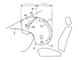
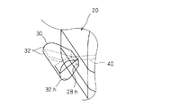
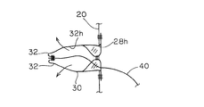
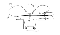
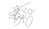
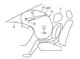
- FIG. 1 is a schematic perspective view showing an inflated form of the airbag device 10
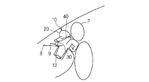
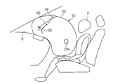
- FIG. 2 is a schematic side view showing an inflated form of the airbag device 10 attached to a dashboard.
- a partially transparent view is shown to show the internal structure of the airbag device 10.
- the airbag device 10 is a device that is incorporated in a dashboard in front of the passenger seat of the vehicle, deploys in front of the passenger in the passenger seat at the time of a vehicle collision, etc., receives the passenger in the passenger seat, and absorbs the impact.
- the airbag apparatus is not limited to the airbag apparatus for the passenger seat, but can be applied to an airbag for a driver's seat incorporated in the steering apparatus.
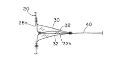
- the airbag device 10 includes an airbag body 20, an inflator 12, an exhaust state switching member 30, and a tether belt 40 as a connecting member.
- the airbag body 20 is formed in an inflatable bag shape, and has a gas supply port 26h and at least one opening 28h.
- the airbag main body 20 is formed into a bag shape by the following configuration, for example. That is, the substantially cylindrical base fabric portion 22 is formed by joining the both edge portions of the substantially strip-shaped cloth by sewing or the like. Also, a pair of side cloth portions 24 having a widened shape capable of closing the side openings of the base cloth portion 22 are prepared, and the side cloth portions are respectively provided on the peripheral edge portions of the both side openings of the base cloth portion 22 formed in a substantially cylindrical shape. 24 edges are joined together by sewing. Thereby, the bag-shaped airbag main body 20 is formed.
- the airbag main body 20 is formed in a shape inflating from the upper side of the inflator 12 toward the occupant side (the rear side of the vehicle, the right side in FIG. 1) and inflating downward at the occupant side portion in a side view.
- the shape and combination of the base fabric for forming the airbag body 20 in a bag shape are not limited to the above example.
- swelling form of the airbag main body 20 is not restricted to the said example.
- the gas supply port 26h is formed at a portion facing the dashboard in an inflated form, more specifically, at a lower portion of the airbag body 20 on the front side of the vehicle (the side away from the passenger, the left side in FIG. 1).
- the inflator 12 is attached to the gas supply port 26h.
- the gas generated in the inflator 12 at the time of a vehicle collision or the like is introduced into the airbag body 20 through the gas supply port 26h.
- the opening 28h is a gas discharge hole.
- the opening 28h is formed in a portion away from the occupant in the inflated form of the airbag body 20, more specifically, at one side of the airbag body 20 in front of the vehicle.
- the opening 28h is formed in a long hole shape extending along the front-rear direction of the airbag body 20 or slightly obliquely from the front-rear direction.
- the opening 28h is not limited to a long hole shape, and may be formed in a circular hole shape, a polygonal hole shape, or a slit shape.
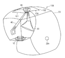
- a second vent hole 29h is formed in the airbag body 20 separately from the opening 28h.
- the second vent hole 29h is formed, for example, on one side or both sides of the airbag body 20 in an inflated form.
- the second vent hole 29h may be the side of the side facing the outside of the vehicle (that is, the door), or the vehicle interior. The side part facing inward may be sufficient.
- the second vent hole 29h is provided for the purpose of gradually discharging the internal air when the airbag body 20 receives an occupant in a normal posture in an inflated form. For this reason, the second vent hole 29h is provided in a portion that appears outside when the airbag main body 20 is inflated, for example, in a vehicle rear side portion (occupant side portion) in an expanded form of the airbag main body 20. Is preferred. Moreover, it is preferable that the gas discharge rate from the second vent hole 29h is such that the internal air can be gradually discharged so as to gradually receive the impact of the passenger.
- the second vent hole 29h is gas at an exhaust speed smaller than an exhaust speed (for example, an amount of gas discharged per unit time under a constant internal gas pressure condition) in an exhaust state of an exhaust state switching member 30 described later. It is preferable that it is set so that it can be discharged.
- the gas discharge speed from the second vent hole 29h is set by adjusting the size and the like.
- the various exhaust patterns can be set by combining the exhaust through the second vent hole 29h and the exhaust mode through the exhaust state switching member 30.
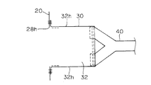
- the exhaust state switching member 30 is provided in the opening 28h, and is in an exhaust state in which the gas in the airbag body 20 can be exhausted before being drawn into the airbag body 20 (FIGS. 5 to 5). 7), when drawn into the airbag body 20, the exhaust state is switched to a non-exhaust state (see FIGS. 1 to 4) that suppresses the exhaust of gas in the airbag body 20. Yes. Then, the exhaust state switching member 30 changes the state between these two states in accordance with the pulling force by the tether belt 40 described later.
- the exhaust state switching member 30 has a pair of belt-like cloths 32.
- One end portions (base end portions) of the pair of belt-like cloths 32 are sewn so as to surround the peripheral edge portion of the opening 28 h in the airbag body 20.
- the exhaust state switching member 30 may be sewn to the airbag body 20 on the outer surface of the airbag body 20.
- the other end portions (tip portions) of the pair of belt-like cloths 32 are stitched together and joined substantially along the width direction.
- both side portions of the pair of belt-like cloths 32 are joined by stitching only their base end portions, and the other portions are in an open state where they are not stitched.
- the 1st vent hole 32h is comprised by the part enclosed by the non-sewing part among the both sides of a pair of strip
- the width dimension of the pair of belt-like cloths 32 is set larger than the width dimension of the opening 28h, and therefore the width dimension of the exhaust state switching member 30 is also set larger than the width dimension of the opening 28h. Yes.
- the exhaust state switching member 30 can pass through the opening 28h while being deformed so as to shrink in the width direction. Resistor is acting.
- the exhaust state switching member 30 is prevented from being inadvertently changed when, for example, a pull-in force by a tether belt 40, which will be described later, or an internal pressure exceeding a predetermined value is not applied to the airbag body 20.
- the exhaust state switching member 30 When the exhaust state switching member 30 is led out of the airbag body 20 together with the first vent hole 32h forming portion, the exhaust state switching member 30 is in an exhaust state in which the gas in the airbag body 20 can be exhausted through the first vent hole 32h. (See FIGS. 5, 6 and 7). On the other hand, when the exhaust state switching member 30 is introduced into the airbag main body 20 together with the first vent hole 32h forming portion, the exhaust state switching member 30 covers the opening 28h so as to block the gas exhaust in the airbag main body 20. (See FIGS. 1 to 4).
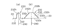
- the configuration of the exhaust state switching member 30 is not limited to the above example.
- the bottom side 232a that is the long side of the pair of substantially trapezoidal cloths 232 is sewn and attached to the opening 28h of the airbag body 20, and
- the upper sides 232b, which are the short sides of the trapezoidal cloth 232, are stitched together and joined.
- one end of the long tether belt 240 is connected to the joint portion of the upper side of the pair of substantially trapezoidal cloths 232.
- a pair of first vent holes 232 h are formed by the portions surrounded by the oblique sides 232 c of the pair of substantially trapezoidal cloths 232.
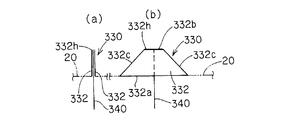
- the bottom side 332a that is the long side of the pair of substantially trapezoidal cloths 332 is sewn and attached to the opening 28h of the airbag body 20, and a pair of substantially Both oblique sides 332c of the trapezoidal cloth 332 are stitched together and joined.
- one end of a long tether belt 340 is connected to each upper side 332b of the pair of substantially trapezoidal cloths 332.
- a first vent hole 332h (refer to a thick line portion) is formed by a portion surrounded by the upper side 332b of the pair of substantially trapezoidal cloths 332.
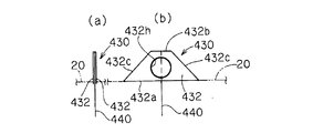
- the bottom side 432a which is the long side of the pair of substantially trapezoidal cloths 432 is sewn and attached to the opening 28h of the airbag body 20, and the pair of substantially trapezoidal cloths 432 Both oblique sides 432c and both upper sides 432b are sewn and joined. Then, one end of a long tether belt 440 is connected to each upper side of the pair of substantially trapezoidal cloths 432. Further, a hole is formed in one or both of the pair of substantially trapezoidal cloths 432, and this is used as a first vent hole 432h.
- the tether belt 40 is a member that connects the exhaust state switching member 30 and a part of the inner peripheral portion of the airbag body 20.
- the tether belt 40 receives the expansion force due to the gas supply from the inflator 12 and causes the exhaust state switching member 30 to move to the airbag main body 20. Pull it in to make it non-exhaust.
- the exhaust state switching member 30 is pulled by the tether belt 40. Is suppressed. As a result, the exhaust state switching member 30 is allowed to change to the exhaust state.
- the tether belt 40 is formed in an elongated band shape by a long member, here, cloth or the like.
- a connecting member a string-like member or the like may be used.
- the tether belt 40 is maintained in a slack state when the airbag body 20 is inflated, particularly when the airbag body 20 comes into contact with an occupant in a non-regular posture in the initial stage of inflation, and the airbag body 20 is in a regular posture in an inflated configuration.
- the tether belt 40 is arranged to be maintained in a pulled state.
- Normal posture means that the occupant seat is adjusted to the expected average position and posture of use, and the average skeleton, height and body occupant leans the torso against the backrest and the head axis is vertical.
- a posture that is like a posture As a normal posture, a state where an occupant wears a seat belt is assumed.
- An example of such a normal posture is FMVSS (Federal Motor Vehicle. Safety Standard) No. issued on August 29, 2011 and effective on December 27, 2011. Those defined in 208 “S7. Seat belt assembly requirements” and “S10. Method of placing test dummy” can be employed.
- the airbag main body 20 When the airbag main body 20 is inflated to receive the above-mentioned normal posture occupant (ie, inflated form), the occupant comes into contact with the rear portion (occupant side portion) of the airbag main body 20, and the airbag main body It sinks deeply into 20 gradually. For this reason, in the rear part of the airbag main body 20, the contact part S1 which the passenger
- the arrangement position of the exhaust state switching member 30 and the inner periphery of the airbag body 20 It is preferable that the connection position of the tether belt 40 with respect to the portion and the passage line of the tether belt 40 are provided in a portion of the inflated form of the airbag body 20 that avoids the contact portion S1.
- the disposition position of the exhaust state switching member 30, the connection position of the tether belt 40 with respect to the inner peripheral portion of the airbag body 20, and the tether belt 40 It is preferable that the passage line is provided at a portion of the inflated form of the airbag body 20 that avoids the deformed portion S2.
- the front half is a front half of the vehicle reference that is divided into two in the front-rear direction of the vehicle, assuming that the airbag body 20 is inflated from the dashboard 8 of the vehicle, and includes the boundary M of the two divisions.
- the position where the exhaust state switching member 30 is disposed, the connection position of the tether belt 40 with respect to the inner periphery of the airbag body 20, and the passage line of the tether belt 40 are defined as passengers whose airbag body 20 is in a normal posture. It is only necessary that the tether belt 40 be disposed in such a manner that the tether belt 40 is not loosened as much as possible.
- each part is disposed in the front part of the vehicle with respect to the deepest part when the occupant in the normal posture sinks deepest with respect to the inflated form of the airbag body 20, the dash
- the board 8 is disposed in the vehicle front side portion of the vehicle rear side portion (occupant side portion), or an inner side of the outer peripheral portion that is not visible to the passenger in the normal posture in the inflated form of the airbag body 20 It is only necessary that the air bag main body 20 is disposed in a portion that is in contact with the front window and in a portion that is disposed below the vicinity thereof in the inflated form of the airbag body 20.
- the passage line of the tether belt 40 is a line through which an intermediate portion of the tether belt 40 passes between connecting portions at both ends of the tether belt 40 in the inflated form of the airbag body 20.
- the straight line is a passing line of the tether belt 40.
- the bent line including the bent portion is the passing line of the tether belt 40.
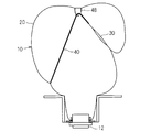
- the annular relay part 48 is provided in the inner peripheral part of the inflation form of the airbag body 20.
- the intermediate portion in the longitudinal direction of the tether belt 40 is supported so as to be movable along the longitudinal direction through the annular relay portion 48.
- the tether belt 40 is disposed so as to bend via the annular relay portion 48.
- the annular relay portion 48 is attached to the inner peripheral portion of the airbag body 20 within the restricted portion, so that the longitudinal intermediate portion of the tether belt 40 passes through the restricted portion. And bent at the annular relay portion 48.
- the center of the tether belt 40 is movably supported by the annular relay portion 48, but other portions, for example, a portion near one end of the tether belt is movably supported by the annular relay portion. Also good.
- the opening 28h is formed in one side of the front portion having a small vertical dimension in the inflated form of the airbag body 20, and the exhaust state switching member 30 is attached to the opening 28h. Accordingly, the exhaust state switching member 30 is provided on one side of the front portion of the airbag body 20 in an inflated form.
- one end of the tether belt 40 is connected to the exhaust state switching member 30.
- both end portions on the distal end side of the exhaust state switching member 30 are connected to the tether belt 40. That is, one end portion of the tether belt 40 is formed to have substantially the same width as the tip portion of the exhaust state switching member 30.
- the tip 52 of the tether belt 40 is formed in a shape that spreads in a Y shape. Then, both end portions extending in a substantially Y shape are sewn on both sides of the distal end portion of the exhaust state switching member 30.
- the tether belt 40 pulls the exhaust state switching member 30 into the airbag body 20 so as to pull both side portions on the distal end side of the exhaust state switching member 30.
- it is not essential that the tip portion of the tether belt 40 is formed in a Y-shaped shape as described above.
- the other end portion of the tether belt 40 is opposite to the other side portion of the front portion of the airbag body 20 in the inflated form, that is, the portion facing the exhaust state switching member 30 in the width direction of the airbag body 20. It is connected to.
- the other end of the tether belt 40 and the airbag body 20 are connected by sewing or the like.
- the annular relay portion 48 is a member formed of the same cloth as the airbag body 20, and is attached to the upper portion of the front portion of the airbag body 20 by sewing or the like so as to be formed in an annular shape. It has been.
- the location where the annular relay portion 48 is attached is a portion facing the inflator 12 or a portion on the rear side (occupant) side of the inflated form of the airbag body 20.
- the location where the annular relay part 48 is attached may be the front side (the side far from the occupant) of the airbag body 20 in the inflated form.
- the tether belt 40 can be disposed so as not to be directly exposed to the gas supplied from the inflator 12.
- it is not essential that the number of the annular relay portions is one, and a plurality of annular relay portions may be provided, and the tether belt may be disposed so as to be bent at each of the plurality of annular relay portions.
- the tether belt 40 is disposed in the front portion of the airbag body 20 in an inflated form so as to reach from the one side portion to the other side portion through the upper annular relay portion 48.
- the length of the tether belt 40 is set to a length dimension that satisfies the following conditions. That is, while the airbag main body 20 is inflating, the airbag main body 20 (particularly, the vicinity of the connection portion of the tether belt 40 and the portion via the annular relay portion 48) is the head or chest of an occupant in an irregular position.
- the length dimension of the tether belt 40 is It is longer than the sum of the distance connecting the opening 28 h of the bag body 20 and the annular relay part 48 and the distance connecting the annular relay part 48 and the connecting portion of the other end of the tether belt 40. Therefore, in this state, the tether belt 40 is loosened, and the exhaust state switching member 30 can be maintained or changed to the exhaust state.
- the airbag body 20 when the airbag body 20 is inflated to the assumed normal shape without being hindered by an occupant in a non-regular posture (hereinafter, the state in which the airbag is inflated to the greatest extent may be referred to as a deployed state 2),
- the sum is set to be larger than the length of the tether belt 40.
- the tether belt 40 receives an inflating force and is pulled between a part of the inner peripheral part of the airbag body 20 and the annular relay part 48 and between the opening 28h and the annular relay part 48 to be in an exhausted state.
- the switching member 30 is pulled into the airbag body 20 to switch to the non-exhaust state.
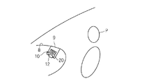
- the airbag device 10 is incorporated in the dashboard 8 of the vehicle as follows. That is, a lid portion 9 that is easily broken when the airbag body 20 is inflated is formed on the upward surface of the dashboard 8. A bracket or the like for attaching the airbag device 10 is attached to the inside of the lid portion 9 of the dashboard 8. The inflator 12 is attached to the bracket, and the airbag device 10 is attached to the inside of the upward surface of the dashboard 8 with the airbag body 20 folded. In a vehicle collision or the like, the gas generated in the inflator 12 is introduced into the airbag body 20 through the gas supply port 26h. Thereby, the airbag main body 20 is inflated, the lid portion 9 is opened, and the airbag 8 is inflated above the dashboard 8 and rearward of the vehicle (occupant side).
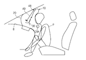
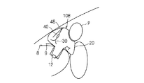
- the non-regular posture refers to one of postures that deviate from the normal posture and whose head is closer to the dashboard 8 side than the normal posture.
- the case where the head and the chest are positioned near the dashboard in front of the vehicle with the occupant P sitting on the occupant seat will be described as an irregular posture.
- the airbag main body 20 hits the head or chest of the occupant P at the initial stage when the airbag main body 20 is inflated.
- the airbag body 20 is prevented from expanding to the occupant side, the distance between the connecting portions on both ends of the tether belt 40 and the annular relay portion 48 is maintained relatively small, and a force that strongly pulls the tether belt 40 acts. It is hard to do.
- the tether belt 40 is in a slack state, and the exhaust state switching member 30 is in an exhaust state.
- the exhaust state switching member 30 may be in the exhaust state in the initial state, or the exhaust state switching member 30 is moved out of the airbag body 20 and switched to the exhaust state by the internal pressure of the airbag body 20. Also good.
- the gas in the airbag main body 20 passes through the exhaust state switching member 30 through the opening 28h and is discharged as quickly as possible from the first vent hole 32h, thereby suppressing rapid expansion and expansion of the airbag main body 20. Is done.
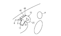
- the airbag body 20 is inflated toward the occupant side without being obstructed by the occupant P or the like.
- the airbag body 20 is inflated to some extent, the distance connecting the opening 28h of the airbag body 20 and the annular relay portion 48, and the connection between the annular relay portion 48 and the other end of the tether belt 40.
- the tether belt 40 is pulled.
- the exhaust state switching member 30 is pulled into the airbag body 20 by the pulling force of the tether belt 40 and switched to the non-exhaust state. For this reason, the airbag main body 20 is rapidly inflated in a state where the exhaust of the gas from the exhaust state switching member 30 is suppressed.
- the airbag body 20 receives the occupant P moving forward due to the impact of the vehicle collision, and absorbs the impact of the occupant P.
- the exhaust of gas through the exhaust state switching member 30 and the opening 28h is suppressed, but the gas is exhausted from the second vent hole 29h.
- the amount of gas discharged from the second vent hole 29h is set to such an extent that the impact of the passenger P can be gradually received as described above. For this reason, the impact of the occupant P is gradually received by the airbag body 20.
- the connecting portion of the exhaust state switching member 30 and the tether belt 40, the passage line, and the like are set to portions that do not deform when the occupant P is received in the inflated form of the airbag body 20.
- the tether belt 40 is maintained in the pulled state, and accordingly, the exhaust of gas through the exhaust state switching member 30 and the opening 28h is suppressed.
- FIG. 20 is a diagram assuming that the occupant P is in a normal posture but does not wear a seat belt. In this case, the occupant P sinks deeper into the airbag body 20.
- connection part and the passage line of the exhaust state switching member 30 and the tether belt 40 are portions that are not deformed even when the passenger P who is not wearing the seat belt is received in the inflated form of the airbag body 20, that is, the airbag body 20 It is preferable to set it in the more forward part of the expanded form. As a result, the tether belt 40 is maintained in a pulled state even while the occupant P who is not wearing the seat belt is being received, and therefore, gas discharge through the exhaust state switching member 30 and the opening 28h is suppressed.
- FIGS. 21 and 22 show an example in which an annular relay part 48C corresponding to the annular relay part 48 is provided at the rear part (occupant side part) of the airbag body 20 as a comparative example.
- the tether belt 40 is loosened at a relatively initial stage, and gas is discharged from the exhaust state switching member 30.
- FIGS. 21 and 22 it is necessary to relatively reduce the exhaust speed of the gas from the exhaust state switching member 30. Then, as a countermeasure against the occupant P in the non-regular posture, the gas exhaust speed becomes insufficient, and another countermeasure needs to be taken.
- the airbag apparatus 10 configured as described above, when the inflated airbag body 20 receives the occupant P in the normal posture, the occupant P contacts the contact portion S1, and thus the tether belt 40 is pulled. Maintained. Thereby, the exhaust state switching member 30 maintains the non-exhaust state. Thereby, sudden discharge of gas can be suppressed and the impact of the passenger
- the occupant P is in the irregular posture state, the occupant P abuts against the airbag body 20 at a portion avoiding the contact portion S1 in the initial stage of inflation of the airbag body 20.
- the loose state of the tether belt 40 is maintained, and the exhaust state switching member 30 maintains the exhaust state or is switched to the exhaust state.
- gas can be discharged from the exhaust state switching member 30 as rapidly as possible, and the airbag main body 20 can be prevented from hitting the occupant P with as much force as possible.
- gas exhaust from the exhaust state switching member 30 can be suppressed even while the occupant P sinks into the airbag body 20, and the impact of the occupant P can be more reliably ensured. You can take it gradually.
- the occupant P comes into contact with the inflated form of the airbag body 20 from the rear (seat side), even if the occupant P is provided in the front half of the inflated form of the airbag body 20, the impact of the occupant P is gradually and more reliably. Can take it.
- the drawing amount of the tether belt 40 is provided. Can be made larger.
- the pull-in amount of the tether belt 40 is only about the difference in distance between the two points that are the connection destinations at both ends of the tether belt 40 between the deployed state 1 and the deployed state 2.
- the tether belt 40 is disposed so as to be bent via the annular relay portion 48 by providing the annular relay portion 48, the amount of the tether belt 40 retracted is between the deployed state 1 and the deployed state 2.
- the difference between the sum of the distance between one connection destination of the tether belt 40 and the annular relay portion 48 and the distance between the other connection destination of the tether belt 40 and the annular relay portion 48 is obtained. For this reason, the pull-in amount of the tether belt 40 for switching between the exhaust state and the non-exhaust state of the exhaust state switching member 30 between the deployed state 1 and the deployed state 2 is increased.
- the difference between the exhaust state and the non-exhaust state (that is, the difference in the degree of exhaust) can be increased, and a more complete non-exhaust state or exhaust state can be easily set.
- annular relay part 48 exists.
- an exhaust state switching member 30 is provided on one side of the inflated form of the airbag body 20, an annular relay part 48 is provided on the upper or front part of the inflated form of the airbag body 20, and one end of the tether belt 40 is In addition to being connected to the exhaust state switching member 30, the tether belt 40 is connected to the inner peripheral portion of the other side portion of the airbag body 20 via the annular relay portion 48, so that the airbag body 20 is inflated.
- the exhaust state switching member 30 can be pulled in more completely by pulling the tether belt 40 more surely and switched to the non-exhaust state more reliably.
- the air bag body 20 is provided with the second vent hole 29h for exhausting gas at an exhaust speed smaller than the exhaust speed of the exhaust state switching member 30 in the exhaust state, the exhaust state switching member 30 is in the exhaust state.
- the airbag main body 20 is normally inflated and catches the occupant P in the normal posture, the gas is gradually discharged from the second vent hole 29h to gradually impact the occupant P. Can take it.
- a switching type exhaust mechanism as shown in FIGS. 21 and 22 may be incorporated.
- the second vent hole 29h may be omitted.
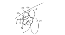
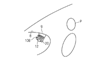
- FIG. 23 is a schematic perspective view showing a modification of the embodiment.
- the flap 100 is provided in the airbag body 20 in the above embodiment.
- the flap 100 is a flexible sheet-like member formed of cloth or the like, and is formed in a square shape here.
- the flap 100 may be a polygon other than a square, a circle, or the like.
- the base end portion 101 (here, one side edge portion) of the flap 100 is connected to the outer peripheral portion of the airbag body 20 by sewing or the like. Further, the distal end portion 102 of the flap 100 opposite to the base end portion 101 covers the airbag body 20 from the initial stage of inflation of the airbag body 20 toward the opposite side of the gas supply port 26h during the inflation. So as to extend.
- the base end portion 101 of the flap 100 is more specifically on the gas supply port 26 h side than the attachment position of the annular relay portion 48 in the airbag body 20 on the outer periphery of the airbag body 20 viewed from the side.
- the airbag main body 20 it connects with the vehicle front side rather than the attachment location of the cyclic
- tip part 102 of the flap 100 has the attachment location of the cyclic
- the flap 100 is provided so as to cover the attachment portion of the annular relay portion 48 from the front portion of the vehicle toward the rear thereof in the airbag main body 20 during or after inflation.
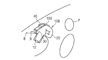
- the airbag body 20 when the airbag body 20 is inflating and the head or chest of an occupant in a non-regular posture is present at a position from the occupant seat from above or above the inflator 12, the airbag 50 is being inflated. Between 20 and the passenger. Thereby, it can suppress that a part of airbag main body 20, especially the peripheral part of the attachment location of the cyclic
- the airbag main body 20 tries to inflate from the dashboard 8 upward and toward the rear of the vehicle (occupant P side).
- the peripheral portion of the airbag body 20 where the annular relay portion 48 is provided is closer to the front of the vehicle than the head or chest of the occupant P. Can be located.
- the flap 100 covers the airbag body 20 in the middle of inflation and faces the occupant P at the occupant P side portion behind the vehicle rather than the peripheral portion where the annular relay portion 48 is provided. For this reason, the flap 100 is sandwiched between the airbag body 20 and the occupant P in the middle of inflation. Since the airbag body 20 starts inflating from the folded state, the airbag body 20 remains in a state where it is folded to some extent in the middle of the inflation.
- the flap 100 when the flap 100 is sandwiched between the airbag body 20 in the middle of inflation and the occupant P, the force to be inflated is received by the flap 100 and the sandwiched portion. The expansion force is difficult to act on. For this reason, the airbag main body 20 is restrained from expanding at the inner portion of the flap 100 and the lower portion of the airbag main body 20 and the tether belt 40 is hardly pulled. As a result, the tether belt 40 is loosened, and the exhaust state switching member 30 is in the exhaust state.
- the gas in the airbag body 20 passes through the exhaust state switching member 30 through the opening 28h and is exhausted to the outside through the first vent hole 32h. Expansion and expansion are suppressed.
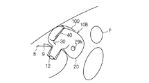
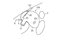
- the flap 100 When the occupant P is in the normal posture, as shown in FIGS. 27 to 30, the flap 100 is only covered over the airbag body 20 in the middle of inflation or in the inflated configuration. Do not touch. For this reason, it can expand
- FIG. 27 When the occupant P is in the normal posture, as shown in FIGS. 27 to 30, the flap 100 is only covered over the airbag body 20 in the middle of inflation or in the inflated configuration. Do not touch. For this reason, it can expand
- one of the connection destinations of the tether belt may be provided at a position from above the airbag body, and the flap may be provided so as to cover the connection portion.
- the flap 100 when the airbag body 20 is inflated for an occupant P in a non-regular posture, the flap 100 abuts on the occupant and is sandwiched between the occupant P and the airbag body 20.
- the partial inflation of the airbag main body 20 is suppressed inside the flap 100.
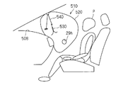
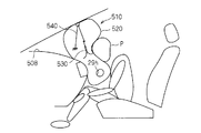
- the airbag apparatus 10 demonstrated in the example provided in the part which faces upwards among the dashboards 8, it corresponds to the airbag apparatus 10 as shown in FIG.31 and FIG.32.
- the airbag device 510 that performs the above may be provided in a portion of the dashboard 508 that faces the occupant P side.
- the position of the exhaust state switching member 530 corresponding to the exhaust state switching member 30 the connection location of the tether belt 540 corresponding to the tether belt 40, the passing line, etc. Is set in the same manner as in the above embodiment, and the same effect as in the above embodiment can be obtained.
- an airbag device may be provided in the middle between the installation position of the above embodiment and the installation positions of FIGS. 31 and 32, that is, a portion facing diagonally rearward of the dashboard.
Landscapes
- Engineering & Computer Science (AREA)
- Mechanical Engineering (AREA)
- Physics & Mathematics (AREA)
- Fluid Mechanics (AREA)
- Air Bags (AREA)
Priority Applications (1)
| Application Number | Priority Date | Filing Date | Title |
|---|---|---|---|
| US14/379,034 US9187058B2 (en) | 2012-02-16 | 2013-02-06 | Airbag device |
Applications Claiming Priority (2)
| Application Number | Priority Date | Filing Date | Title |
|---|---|---|---|
| JP2012-031668 | 2012-02-16 | ||
| JP2012031668A JP5892807B2 (ja) | 2012-02-16 | 2012-02-16 | エアバッグ装置 |
Publications (1)
| Publication Number | Publication Date |
|---|---|
| WO2013121950A1 true WO2013121950A1 (ja) | 2013-08-22 |
Family
ID=48984062
Family Applications (1)
| Application Number | Title | Priority Date | Filing Date |
|---|---|---|---|
| PCT/JP2013/052720 Ceased WO2013121950A1 (ja) | 2012-02-16 | 2013-02-06 | エアバッグ装置 |
Country Status (3)
| Country | Link |
|---|---|
| US (1) | US9187058B2 (enExample) |
| JP (1) | JP5892807B2 (enExample) |
| WO (1) | WO2013121950A1 (enExample) |
Families Citing this family (7)
| Publication number | Priority date | Publication date | Assignee | Title |
|---|---|---|---|---|
| JP6574554B2 (ja) * | 2014-06-26 | 2019-09-11 | 日本プラスト株式会社 | エアバッグ |
| US9199602B1 (en) * | 2014-07-23 | 2015-12-01 | Trw Vehicle Safety Systems Inc. | Passive air bag with slack creator |
| US9676364B2 (en) * | 2015-09-30 | 2017-06-13 | Autoliv Asp, Inc. | Airbag systems with passive venting control |
| US10099647B2 (en) * | 2016-09-21 | 2018-10-16 | Ford Global Technologies, Llc | Airbag assembly |
| US10214174B2 (en) * | 2017-01-30 | 2019-02-26 | Toyoda Gosei Co., Ltd. | Vehicle airbag apparatus |
| US11254273B2 (en) * | 2018-10-19 | 2022-02-22 | Toyota Motor Engineering & Manufacturing North America, Inc. | Venting of airbag for adjustment of cushioning surface position |
| US11518335B2 (en) * | 2019-07-02 | 2022-12-06 | Joyson Safety Systems Acquisition Llc | Driver side airbag module |
Citations (4)
| Publication number | Priority date | Publication date | Assignee | Title |
|---|---|---|---|---|
| JP2008201214A (ja) * | 2007-02-19 | 2008-09-04 | Takata Corp | エアバッグ及びエアバッグ装置 |
| JP2009143483A (ja) * | 2007-12-17 | 2009-07-02 | Takata Corp | 助手席用エアバッグ、助手席用エアバッグ装置及び自動車 |
| JP2009196596A (ja) * | 2008-02-25 | 2009-09-03 | Takata Corp | エアバッグ及びエアバッグ装置 |
| JP2009196551A (ja) * | 2008-02-22 | 2009-09-03 | Toyota Motor Corp | 車両用エアバッグ装置 |
Family Cites Families (16)
| Publication number | Priority date | Publication date | Assignee | Title |
|---|---|---|---|---|
| US7364192B2 (en) * | 2002-09-16 | 2008-04-29 | Trw Vehicle Safety Systems Inc. | Air bag module with locking member for locking the position of a vent member |
| US7347450B2 (en) * | 2004-10-06 | 2008-03-25 | Autoliv Asp, Inc. | Airbag cushion with cinch tube for reduced out-of-position effects |
| US7328915B2 (en) * | 2004-10-06 | 2008-02-12 | Autoliv Asp, Inc. | Airbag cushion with tether deactivated venting for reduced out-of-position effects |
| US7261319B2 (en) * | 2005-01-07 | 2007-08-28 | Autoliv Asp, Inc. | Airbag cushion with adaptive venting for reduced out-of-position effects |
| JP5045017B2 (ja) | 2005-08-24 | 2012-10-10 | タカタ株式会社 | エアバッグ及びエアバッグ装置 |
| DE602006001275D1 (de) | 2005-08-24 | 2008-07-03 | Takata Corp | Gassack und Gassackeinrichtung |
| JP2007099122A (ja) | 2005-10-05 | 2007-04-19 | Takata Corp | エアバッグ及びエアバッグ装置 |
| JP5053658B2 (ja) | 2007-02-23 | 2012-10-17 | 日本プラスト株式会社 | エアバッグ装置 |
| JP4992853B2 (ja) * | 2008-08-06 | 2012-08-08 | タカタ株式会社 | エアバッグ装置 |
| JP4666059B2 (ja) | 2008-11-12 | 2011-04-06 | トヨタ自動車株式会社 | 車両用エアバッグ装置 |
| US8590927B2 (en) * | 2010-04-19 | 2013-11-26 | Tk Holdings Inc. | Airbag module |
| US8678431B2 (en) * | 2010-10-27 | 2014-03-25 | Trw Vehicle Safety Systems | Air bag with tether and pulley arrangement |
| US8696022B2 (en) * | 2010-10-27 | 2014-04-15 | Trw Vehicle Safety Systems Inc. | Air bag with variable venting |
| US8684404B2 (en) * | 2010-10-27 | 2014-04-01 | Trw Vehicle Safety Systems Inc. | Air bag with variable venting |
| US8684407B2 (en) * | 2010-10-27 | 2014-04-01 | Trw Vehicle Safety Systems Inc. | Air bag with height adaptive tether |
| KR101438965B1 (ko) * | 2012-12-26 | 2014-09-11 | 현대자동차주식회사 | 차량의 에어백 장치 |
-
2012
- 2012-02-16 JP JP2012031668A patent/JP5892807B2/ja active Active
-
2013
- 2013-02-06 WO PCT/JP2013/052720 patent/WO2013121950A1/ja not_active Ceased
- 2013-02-06 US US14/379,034 patent/US9187058B2/en active Active
Patent Citations (4)
| Publication number | Priority date | Publication date | Assignee | Title |
|---|---|---|---|---|
| JP2008201214A (ja) * | 2007-02-19 | 2008-09-04 | Takata Corp | エアバッグ及びエアバッグ装置 |
| JP2009143483A (ja) * | 2007-12-17 | 2009-07-02 | Takata Corp | 助手席用エアバッグ、助手席用エアバッグ装置及び自動車 |
| JP2009196551A (ja) * | 2008-02-22 | 2009-09-03 | Toyota Motor Corp | 車両用エアバッグ装置 |
| JP2009196596A (ja) * | 2008-02-25 | 2009-09-03 | Takata Corp | エアバッグ及びエアバッグ装置 |
Also Published As
| Publication number | Publication date |
|---|---|
| US20150084318A1 (en) | 2015-03-26 |
| JP5892807B2 (ja) | 2016-03-23 |
| JP2013166495A (ja) | 2013-08-29 |
| US9187058B2 (en) | 2015-11-17 |
Similar Documents
| Publication | Publication Date | Title |
|---|---|---|
| JP6624308B2 (ja) | 乗員の頭部の回転速度を低下させるための前面エアバッグアセンブリ | |
| EP2496446B1 (en) | Vehicle with a low-mount inflatable knee airbag having serial chambers | |
| US7992897B2 (en) | Airbag device | |
| JP5892807B2 (ja) | エアバッグ装置 | |
| JP4434193B2 (ja) | 車両用サイドエアバッグ装置 | |
| CN114174128B (zh) | 安全气囊装置 | |
| US8517415B2 (en) | Airbag apparatus | |
| JP7138591B2 (ja) | エアバッグ装置 | |
| JP4193578B2 (ja) | 乗員脚部保護装置 | |
| EP3141437A1 (en) | Far side airbag device and vehicle seat | |
| WO2012091656A1 (en) | Curtain airbag for a vehicle | |
| JP2008184159A (ja) | 乗員保護装置 | |
| JP6939179B2 (ja) | エアバッグ及び乗員拘束装置 | |
| CN110869248A (zh) | 乘员保护装置 | |
| JP2015157602A (ja) | 乗員保護装置 | |
| CN114450199A (zh) | 安全气囊装置及车辆用座椅 | |
| KR20230016684A (ko) | 에어백 장치 | |
| WO2013038827A1 (ja) | 助手席用エアバッグ、助手席用エアバッグ装置及び車両 | |
| US11186249B2 (en) | Passenger airbag | |
| JP5792601B2 (ja) | エアバッグ装置 | |
| JP4781078B2 (ja) | エアバッグ装置 | |
| JP2024522999A (ja) | 展開支援ラッパーを備えた前面エアバッグシステム | |
| JP4781077B2 (ja) | エアバッグ装置 | |
| JP3539312B2 (ja) | 車両用乗員保護装置 | |
| JP2005313675A (ja) | エアバッグ装置 |
Legal Events
| Date | Code | Title | Description |
|---|---|---|---|
| 121 | Ep: the epo has been informed by wipo that ep was designated in this application |
Ref document number: 13748951 Country of ref document: EP Kind code of ref document: A1 |
|
| WWE | Wipo information: entry into national phase |
Ref document number: 14379034 Country of ref document: US |
|
| NENP | Non-entry into the national phase |
Ref country code: DE |
|
| 122 | Ep: pct application non-entry in european phase |
Ref document number: 13748951 Country of ref document: EP Kind code of ref document: A1 |