WO2013108548A1 - Dispositif générateur de microbulles - Google Patents
Dispositif générateur de microbulles Download PDFInfo
- Publication number
- WO2013108548A1 WO2013108548A1 PCT/JP2012/083283 JP2012083283W WO2013108548A1 WO 2013108548 A1 WO2013108548 A1 WO 2013108548A1 JP 2012083283 W JP2012083283 W JP 2012083283W WO 2013108548 A1 WO2013108548 A1 WO 2013108548A1
- Authority
- WO
- WIPO (PCT)
- Prior art keywords
- gas
- liquid
- forming body
- nozzle
- spiral
- Prior art date
Links
Images

Classifications
-
- B—PERFORMING OPERATIONS; TRANSPORTING
- B01—PHYSICAL OR CHEMICAL PROCESSES OR APPARATUS IN GENERAL
- B01F—MIXING, e.g. DISSOLVING, EMULSIFYING OR DISPERSING
- B01F23/00—Mixing according to the phases to be mixed, e.g. dispersing or emulsifying
- B01F23/20—Mixing gases with liquids
- B01F23/23—Mixing gases with liquids by introducing gases into liquid media, e.g. for producing aerated liquids
- B01F23/232—Mixing gases with liquids by introducing gases into liquid media, e.g. for producing aerated liquids using flow-mixing means for introducing the gases, e.g. baffles
- B01F23/2323—Mixing gases with liquids by introducing gases into liquid media, e.g. for producing aerated liquids using flow-mixing means for introducing the gases, e.g. baffles by circulating the flow in guiding constructions or conduits
-
- B—PERFORMING OPERATIONS; TRANSPORTING
- B01—PHYSICAL OR CHEMICAL PROCESSES OR APPARATUS IN GENERAL
- B01F—MIXING, e.g. DISSOLVING, EMULSIFYING OR DISPERSING
- B01F23/00—Mixing according to the phases to be mixed, e.g. dispersing or emulsifying
- B01F23/20—Mixing gases with liquids
- B01F23/23—Mixing gases with liquids by introducing gases into liquid media, e.g. for producing aerated liquids
- B01F23/237—Mixing gases with liquids by introducing gases into liquid media, e.g. for producing aerated liquids characterised by the physical or chemical properties of gases or vapours introduced in the liquid media
- B01F23/2373—Mixing gases with liquids by introducing gases into liquid media, e.g. for producing aerated liquids characterised by the physical or chemical properties of gases or vapours introduced in the liquid media for obtaining fine bubbles, i.e. bubbles with a size below 100 µm
-
- B—PERFORMING OPERATIONS; TRANSPORTING
- B01—PHYSICAL OR CHEMICAL PROCESSES OR APPARATUS IN GENERAL
- B01F—MIXING, e.g. DISSOLVING, EMULSIFYING OR DISPERSING
- B01F25/00—Flow mixers; Mixers for falling materials, e.g. solid particles
- B01F25/30—Injector mixers
- B01F25/31—Injector mixers in conduits or tubes through which the main component flows
- B01F25/312—Injector mixers in conduits or tubes through which the main component flows with Venturi elements; Details thereof
- B01F25/3124—Injector mixers in conduits or tubes through which the main component flows with Venturi elements; Details thereof characterised by the place of introduction of the main flow
- B01F25/31241—Injector mixers in conduits or tubes through which the main component flows with Venturi elements; Details thereof characterised by the place of introduction of the main flow the main flow being injected in the circumferential area of the venturi, creating an aspiration in the central part of the conduit
-
- B—PERFORMING OPERATIONS; TRANSPORTING
- B01—PHYSICAL OR CHEMICAL PROCESSES OR APPARATUS IN GENERAL
- B01F—MIXING, e.g. DISSOLVING, EMULSIFYING OR DISPERSING
- B01F25/00—Flow mixers; Mixers for falling materials, e.g. solid particles
- B01F25/30—Injector mixers
- B01F25/31—Injector mixers in conduits or tubes through which the main component flows
- B01F25/312—Injector mixers in conduits or tubes through which the main component flows with Venturi elements; Details thereof
- B01F25/3125—Injector mixers in conduits or tubes through which the main component flows with Venturi elements; Details thereof characteristics of the Venturi parts
- B01F25/31251—Throats
- B01F25/312512—Profiled, grooved, ribbed throat, or being provided with baffles
-
- B—PERFORMING OPERATIONS; TRANSPORTING
- B01—PHYSICAL OR CHEMICAL PROCESSES OR APPARATUS IN GENERAL
- B01F—MIXING, e.g. DISSOLVING, EMULSIFYING OR DISPERSING
- B01F25/00—Flow mixers; Mixers for falling materials, e.g. solid particles
- B01F2025/91—Direction of flow or arrangement of feed and discharge openings
- B01F2025/913—Vortex flow, i.e. flow spiraling in a tangential direction and moving in an axial direction
Definitions
- the present invention relates to a fine bubble generating device for generating fine bubbles in a liquid by performing gas-liquid mixing using a swirling flow.
- a gas-liquid two-phase high-speed swirling method is known as a method for generating microbubbles such as microbubbles in the liquid.
- the liquid is swung at high speed along the cylindrical surface in the nozzle to generate a negative pressure at the center of the nozzle (along the axis).
- gas is introduced into the nozzle by this negative pressure to form a gas-liquid two-phase swirl flow that swirls at high speed.
- This swirling flow is contracted along the axis and released from the nozzle outlet to shear the gas-liquid two-phase fluid and generate fine bubbles (see, for example, Patent Documents 1 and 2).
- high-pressure liquid is guided to the gas-liquid mixing space in the nozzle through the spiral flow path, thereby forming a spiral high-speed swirling flow along the cylindrical inner peripheral surface of the gas-liquid mixing space.
- the spiral flow path is formed by fitting a cylindrical portion provided with spiral blades on the outer periphery thereof to a cylinder provided in a nozzle body having an inner diameter substantially equal to the outer diameter of the blades.
- JP 2006-142251 A Japanese Patent No. 4376888
- Patent Documents 1 and 2 have a problem in durability.
- This invention makes it a subject to improve the durability with respect to the high pressure fluid of a spiral flow path in the microbubble generator using a gas-liquid two-phase high-speed swirling system.
- the swirling passage forming body of the present invention supplies a pressurized liquid through a spiral passage into a nozzle to generate a swirling flow in the nozzle, and introduces gas into the nozzle using negative pressure generated by the swirling flow.
- It is a swirl passage forming body that is attached to a microbubble generator that forms a liquid two-phase swirl flow and generates gas bubbles by shearing the gas-liquid two-phase fluid by ejecting the gas-liquid two-phase swirl flow from the nozzle outlet.
- the inlet part of the blade is raised. Thereby, a strong swirling flow can be generated by lowering the pressure loss of the supplied liquid and increasing the flow velocity of the ejected liquid.
- a plurality of blades are provided and the plurality of blades do not overlap in the central axis direction. Thereby, a spiral channel
- the plurality of blades are preferably composed of two blades arranged 180 ° apart, and each blade is formed over a half circumference of the outer peripheral surface.
- the main body, the blades, and the outer cylindrical portion are integrally formed by molding.
- the swirl passage forming body is made of polyphenylene sulfide (PPS) resin.
- the fine bubble generation device of the present invention is any one of the fine bubble generation devices using the spiral passage forming body, further comprising: a liquid supply unit attached to the nozzle; and a gas supply unit provided in the liquid supply unit.
- the spiral passage forming body is fitted into a cylindrical accommodating portion formed in the nozzle, and the accommodating portion is provided with a step portion for receiving the outer cylindrical portion of the spiral passage forming body.
- the liquid supply part is inserted into the nozzle and fixed to the nozzle, the tip of the liquid supply part inserted into the nozzle is in contact with the outer cylindrical part of the spiral path forming body, and the spiral path forming body is formed between the stepped part and the tip part. Held in between.
- a gas introduction pipe from the gas supply section is arranged along the liquid passage of the liquid supply section, and the gas introduction pipe is connected to the gas introduction hole of the spiral passage formation body.
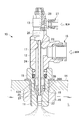
- FIG. 1 is a cross-sectional view showing a configuration of a fine bubble generating apparatus according to an embodiment of the present invention.
- the microbubble generator 10 includes a nozzle 11 that generates microbubbles such as microbubbles in a liquid, a liquid supply unit 12 that supplies liquid pressurized to the nozzle 11, and a gas supply unit that supplies gas to the nozzle 11. 13 is provided.
- the nozzle 11 is fixed to the wall surface 14 of the tank that stores the liquid L, for example, and the tip thereof is disposed in the liquid L.
- the nozzle 11 includes a shoulder portion 15, and the tip of the nozzle 11 is inserted into a hole formed in the wall surface 14, and a nut 16 is screwed to the tip of the nozzle 11.
- the nozzle 11 is fixed to the tank wall surface 14 by holding the wall surface 14 therebetween.
- the liquid supply unit 12 includes, for example, an L-shaped liquid passage 17, and the outer shape thereof also has an outer shape along the L-shape.
- a pipe joint portion 18 is provided at an open end extending sideways, and a pipe (not shown) connected to a pressure pump or the like is connected to the pipe joint portion 18. That is, the pressurized liquid is supplied from the pressurizing pump to the liquid passage 17.
- the other open end of the liquid passage 17 is connected to a rotationally symmetric space formed in the nozzle 11.
- a large-diameter cylindrical space (accommodating portion) 20 that accommodates a spiral passage forming body 19 to be described later is provided, and a reduced diameter portion 21 that is reduced in a conical shape is provided at the tip.
- a small-diameter cylindrical space (gas-liquid mixing unit) 22 that generates a gas-liquid two-phase swirl flow is provided at the tip of the reduced diameter unit 21.
- the gas-liquid mixing part 22 is opened to the outside of the nozzle after being reduced in diameter at the tip.
- a small hole 23 is formed on the side opposite to the opening of the liquid passage 17 connected to the nozzle 11 (the base portion bent in an L shape), and the gas introduction pipe 24 from the gas supply unit 13 is hermetically communicated.
- the gas introduction pipe 24 extending into the liquid passage 17 extends substantially along the center of the liquid passage 17, and the tip portion thereof extends into the gas introduction hole 25 of the spiral passage formation body 19 installed in the housing portion 20. Installed.
- the gas supply section 13 is formed with an L-shaped gas passage 26 through which gas is circulated, and a pipe joint 27 is provided at an open end extending sideways. That is, a desired gas is supplied to the gas passage 26 from a pipe (not shown) connected to the pipe joint 27. Further, a flow rate adjusting valve 28 such as a needle screw is provided in, for example, an L-shaped bent portion of the gas passage 26, and the flow rate of the gas supplied to the gas introduction pipe 24 is adjusted.
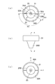
- FIGS. 2 (a) to 2 (c) are a top view, a side view, and a bottom view of the spiral passage forming body 19 of this embodiment
- FIG. 3 (a) is a cross-sectional view taken along line A-- in FIG. 2 (b).
- FIGS. 3B and 3C are cross-sectional views taken along the line A ′ in FIG. 2C, and are arrow views from the B direction and the C direction in FIG.
- the main body 29 of the spiral passage forming body 19 is composed of a cylindrical columnar portion 29A and a truncated cone portion 29B protruding in a truncated cone shape from the lower end of the cylindrical portion 29A.
- a pair of spiral blades 30A and 30B are provided on the outer peripheral surface of the portion 29A.
- a cylindrical outer cylindrical portion 31 is provided on the outer peripheral edge of the spiral blades 30A and 30B.
- the height of the outer cylindrical portion 31 is, for example, equal to the height of the columnar portion 29A, and the outer diameter of the bottom surface of the truncated cone portion 29B is equal to the outer diameter of the columnar portion 29A.
- the gas introduction hole 25 is formed in the center of the main body 29 along a cylindrical axis (conical axis).
- the spiral blades 30A and 30B start from a position separated from the central axis of the main body 29 by 180 °, and are respectively provided over a half circumference (180 °) along the outer peripheral surface of the cylindrical portion 29A. .
- the blades do not overlap in the axial direction like a double helix.
- the blades 30A and 30B forming the spiral passage are raised near the top surface to form the spiral passage inlet portions 32A and 32B (see particularly FIG. 3C).
- the spiral passage inlet portions 32A and 32B are provided in a range of an angle ⁇ 1 centering on the axis of the main body 29, and the remaining range of the angle ⁇ 2 is a blade 30A having a constant lead angle. , 30B.
- the angles ⁇ 1 and ⁇ 2 are set to about 30 ° and 150 °, for example, with a tolerance of ⁇ 10 °, and the lead angle of the main body portion (range of angle ⁇ 2) of the blades 30A and 30B is set to, for example, 5 ° to 10 °. Is done.
- the extreme end portions (upstream side) of the rising portions of the spiral passage inlet portions 32A and 32B are approximately 90 °.
- a step portion 20 ⁇ / b> A having a width substantially the same as the thickness of the outer cylindrical portion 31 is formed at the connection portion between the accommodating portion 20 and the reduced diameter portion 21 of the nozzle 11.
- the front end portion 12A of the liquid supply unit 12 has a cylindrical shape having substantially the same diameter and thickness as the outer cylindrical portion 31, and the liquid supply unit 12 is connected to the nozzle 20 after the helical passage forming body 19 is mounted on the storage unit 20. 11 is attached to the upper end portion of the outer cylindrical portion 31. Thereby, the position of the spiral passage forming body 19 is fixed in the accommodating portion 20.
- the tip of the conical portion 29B of the spiral passage forming body 19 is positioned at the entrance height of the gas-liquid mixing portion 22 at this time.
- the pressurized fluid supplied to the liquid passage 17 is guided from the inlet portion (32A, 32B) of the spiral passage forming body 19 to the reduced diameter portion 21 along the spiral blades (30A, 30B), and is directed downward in the circumferential direction. Is erupted.
- the liquid is guided spirally along the conical surface of the diameter-reduced portion 21 to the gas-liquid mixing portion 22, further increased in speed, and rotated at a high speed along the cylindrical inner peripheral surface of the gas-liquid mixing portion 22. It flows toward the opening of the part.
- the peripheral edge of the spiral blade provided in the spiral passage forming body used in the fine bubble generating device is reinforced by the cylindrical portion. Can give the blades sufficient strength.
- the spiral path forming body can be integrally formed by molding.
- the double spiral structure cannot be adopted as in the preceding example, and the length of the spiral passage is shortened. For this reason, the run-up distance of the spiral flow is shortened, and the efficiency of the swirl flow is reduced. It is conceivable to compensate for this by increasing the supplied fluid pressure, but increasing the pressure and increasing the flow velocity of the spiral passage increases the pressure loss at the inlet portion of the spiral passage.
- the spiral pitch is discontinuously changed at the entrance, but the pitch can be continuously increased toward the entrance in the entire spiral passage or in the entrance.
- the spiral passage forming body is made of polyphenylene sulfide (PPS) resin.
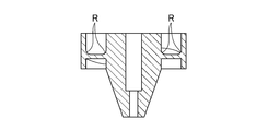
- FIG. 4 shows a modification of the spiral passage forming body.
- corners where the outer side wall 31 and the blades 30A and 30B and the cylindrical portion 29A are connected are provided with R (formed in a curved shape such as an arc), and are formed by these wall surfaces.
- R formed in a curved shape such as an arc
Abstract
Cette invention concerne un dispositif générateur de microbulles dans lequel un fluide sous pression est introduit dans un passage pour liquide (17) d'une unité d'alimentation en liquide (12). Le liquide est guidé et pulvérisé, vers une section de diamètre réduit (21), située en dessous du passage pour liquide (17) dans le sens circonférentiel d'une lame hélicoïdale, ladite lame hélicoïdale se trouvant du côté intérieur de la section cylindrique côté extérieur d'un corps formant passage hélicoïdal (19). Le liquide pulvérisé est guidé le long de la surface conique de la section à diamètre réduit (21) de forme hélicoïdale vers une section de mélange gaz/liquide (22) et accéléré, et un flux tourbillonnant à grande vitesse qui s'écoule en direction de l'extrémité de la buse est généré dans la section de mélange gaz/liquide (22). Une pression négative générée au centre de la section de mélange gaz/liquide (22) par le flux tourbillonnant à grande vitesse aspire le gaz dans la section de mélange gaz/liquide (22) à partir d'un tuyau d'entrée de gaz (24), et un fluide tourbillonnant biphasique gaz/liquide est généré. Le fluide tourbillonnant biphasique gaz/liquide est pulvérisé/libéré à partir de l'ouverture d'extrémité de la section de mélange gaz/liquide (22) qui a un diamètre réduit vers l'extérieur de la buse, cisaillant ainsi le fluide biphasique gaz/liquide et générant des microbulles.
Priority Applications (2)
| Application Number | Priority Date | Filing Date | Title |
|---|---|---|---|
| KR1020147007192A KR20140112469A (ko) | 2012-01-19 | 2012-12-21 | 미세 기포 발생 장치 |
| CN201280065910.7A CN104039432B (zh) | 2012-01-19 | 2012-12-21 | 微气泡发生装置 |
Applications Claiming Priority (2)
| Application Number | Priority Date | Filing Date | Title |
|---|---|---|---|
| JP2012009064A JP5801210B2 (ja) | 2012-01-19 | 2012-01-19 | 微細気泡発生装置 |
| JP2012-009064 | 2012-01-19 |
Publications (1)
| Publication Number | Publication Date |
|---|---|
| WO2013108548A1 true WO2013108548A1 (fr) | 2013-07-25 |
Family
ID=48798984
Family Applications (1)
| Application Number | Title | Priority Date | Filing Date |
|---|---|---|---|
| PCT/JP2012/083283 WO2013108548A1 (fr) | 2012-01-19 | 2012-12-21 | Dispositif générateur de microbulles |
Country Status (5)
| Country | Link |
|---|---|
| JP (1) | JP5801210B2 (fr) |
| KR (1) | KR20140112469A (fr) |
| CN (1) | CN104039432B (fr) |
| TW (1) | TWI579039B (fr) |
| WO (1) | WO2013108548A1 (fr) |
Cited By (1)
| Publication number | Priority date | Publication date | Assignee | Title |
|---|---|---|---|---|
| WO2022218636A1 (fr) * | 2021-04-15 | 2022-10-20 | Messer Se & Co. Kgaa | Dispositif et procédé de dispersion de gaz dans des liquides |
Families Citing this family (8)
| Publication number | Priority date | Publication date | Assignee | Title |
|---|---|---|---|---|
| KR20190042081A (ko) * | 2016-09-28 | 2019-04-23 | 쿼터스 파울루스 보타 | 나노 버블 발생기 및 나노 버블 발생 방법 |
| EP3530629A4 (fr) * | 2016-10-21 | 2019-09-25 | Tech Corporation Co. Ltd. | Procédé de traitement de surface pour agrégat de sable et procédé de production de béton prêt-à-l'emploi |
| JP6889594B2 (ja) * | 2017-04-13 | 2021-06-18 | 東芝ライフスタイル株式会社 | 食器洗浄機 |
| CN107261875B (zh) * | 2017-07-03 | 2020-06-12 | 贺生源健康生技股份有限公司 | 一种微细及超微细气泡产生模块及其应用装置 |
| TWI629247B (zh) * | 2017-08-22 | 2018-07-11 | 阮慶源 | Microbubble generator |
| CN109954475A (zh) * | 2017-12-25 | 2019-07-02 | 中核建中核燃料元件有限公司 | 一种干法制备uo2粉末工艺过程中的喷嘴 |
| KR102132815B1 (ko) * | 2018-09-19 | 2020-07-21 | 공성욱 | 미세 기포 발생 장치 |
| TWI768813B (zh) * | 2021-04-07 | 2022-06-21 | 蘇玟足 | 氣泡產生裝置 |
Citations (7)
| Publication number | Priority date | Publication date | Assignee | Title |
|---|---|---|---|---|
| US1367769A (en) * | 1919-08-11 | 1921-02-08 | Cooling Tower Company Inc | Spray-nozzle |
| JPH0184728U (fr) * | 1987-11-25 | 1989-06-06 | ||
| JPH07284642A (ja) * | 1994-04-19 | 1995-10-31 | Hisao Kojima | ミキシングエレメント及びその製造方法 |
| JP2007021343A (ja) * | 2005-07-14 | 2007-02-01 | Kansai Automation Kiki Kk | マイクロバブル発生装置 |
| JP2007211679A (ja) * | 2006-02-09 | 2007-08-23 | Mitsubishi Electric Corp | 円周流ポンプ |
| WO2007122731A1 (fr) * | 2006-04-24 | 2007-11-01 | Nitta Moore Company | Générateur de microbulles |
| WO2008056663A1 (fr) * | 2006-11-08 | 2008-05-15 | Nitta Moore Company | Appareil de génération de fines bulles |
Family Cites Families (12)
| Publication number | Priority date | Publication date | Assignee | Title |
|---|---|---|---|---|
| JPS59115424U (ja) * | 1983-01-20 | 1984-08-04 | 小嶋 久夫 | 流体混合加熱器 |
| US4522504A (en) * | 1983-12-08 | 1985-06-11 | Pyles Division | Linear in-line mixing system |
| JPS6287232A (ja) * | 1985-10-14 | 1987-04-21 | Hisao Kojima | 静止型混合具 |
| JPH04322731A (ja) * | 1991-03-12 | 1992-11-12 | Kimitoshi Mato | 気体溶解方法及び装置 |
| JP2004042027A (ja) * | 2002-05-22 | 2004-02-12 | Kao Corp | 混合用アタッチメント |
| WO2005103447A1 (fr) * | 2004-04-26 | 2005-11-03 | Axsia Serck Baker Limited | Separateurs de tete de puits ameliores |
| JP4545564B2 (ja) * | 2004-11-24 | 2010-09-15 | ニッタ・ムアー株式会社 | 微細気泡発生装置 |
| JP5269493B2 (ja) * | 2008-06-18 | 2013-08-21 | 佐藤工業株式会社 | マイクロバブル発生装置 |
| JP5028637B2 (ja) * | 2009-01-28 | 2012-09-19 | 中村物産有限会社 | 微細気泡発生装置 |
| JP2010234242A (ja) * | 2009-03-31 | 2010-10-21 | Mitsubishi Materials Corp | 微細気泡発生装置 |
| JP2010253396A (ja) * | 2009-04-24 | 2010-11-11 | Nitta Moore Co | マイクロバブル発生装置及びマイクロバブル発生方法 |
| JP5441746B2 (ja) * | 2010-02-05 | 2014-03-12 | 旭有機材工業株式会社 | 流体混合器および流体混合器を用いた装置 |
-
2012
- 2012-01-19 JP JP2012009064A patent/JP5801210B2/ja active Active
- 2012-12-21 WO PCT/JP2012/083283 patent/WO2013108548A1/fr active Application Filing
- 2012-12-21 KR KR1020147007192A patent/KR20140112469A/ko not_active Application Discontinuation
- 2012-12-21 CN CN201280065910.7A patent/CN104039432B/zh active Active
- 2012-12-27 TW TW101150436A patent/TWI579039B/zh active
Patent Citations (7)
| Publication number | Priority date | Publication date | Assignee | Title |
|---|---|---|---|---|
| US1367769A (en) * | 1919-08-11 | 1921-02-08 | Cooling Tower Company Inc | Spray-nozzle |
| JPH0184728U (fr) * | 1987-11-25 | 1989-06-06 | ||
| JPH07284642A (ja) * | 1994-04-19 | 1995-10-31 | Hisao Kojima | ミキシングエレメント及びその製造方法 |
| JP2007021343A (ja) * | 2005-07-14 | 2007-02-01 | Kansai Automation Kiki Kk | マイクロバブル発生装置 |
| JP2007211679A (ja) * | 2006-02-09 | 2007-08-23 | Mitsubishi Electric Corp | 円周流ポンプ |
| WO2007122731A1 (fr) * | 2006-04-24 | 2007-11-01 | Nitta Moore Company | Générateur de microbulles |
| WO2008056663A1 (fr) * | 2006-11-08 | 2008-05-15 | Nitta Moore Company | Appareil de génération de fines bulles |
Cited By (1)
| Publication number | Priority date | Publication date | Assignee | Title |
|---|---|---|---|---|
| WO2022218636A1 (fr) * | 2021-04-15 | 2022-10-20 | Messer Se & Co. Kgaa | Dispositif et procédé de dispersion de gaz dans des liquides |
Also Published As
| Publication number | Publication date |
|---|---|
| JP2013146683A (ja) | 2013-08-01 |
| TWI579039B (zh) | 2017-04-21 |
| JP5801210B2 (ja) | 2015-10-28 |
| CN104039432B (zh) | 2017-07-21 |
| KR20140112469A (ko) | 2014-09-23 |
| CN104039432A (zh) | 2014-09-10 |
| TW201345606A (zh) | 2013-11-16 |
Similar Documents
| Publication | Publication Date | Title |
|---|---|---|
| JP5801210B2 (ja) | 微細気泡発生装置 | |
| WO2017179222A1 (fr) | Dispositif de génération de microbulles | |
| US10245602B2 (en) | Atomizer nozzle | |
| CN106660842B (zh) | 微气泡喷嘴 | |
| CN108348933B (zh) | 喷嘴和混合流体流的方法 | |
| US20180326374A1 (en) | Microbubble generating device | |
| JP2014207893A (ja) | 噴霧器 | |
| JP5807783B2 (ja) | 微細気泡発生装置および旋回流形成体 | |
| JP6151555B2 (ja) | 流体吸引混合装置 | |
| JP2019166493A (ja) | 微細気泡発生ノズル | |
| RU2482925C1 (ru) | Центробежная вихревая форсунка кочетова | |
| JP5257586B2 (ja) | 旋回式微細気泡発生器 | |
| JP2012239953A (ja) | 旋回式微細気泡発生装置 | |
| RU2342597C1 (ru) | Акустическая форсунка для распыливания жидкостей | |
| RU145896U1 (ru) | Центробежно-струйная форсунка | |
| JP2012045537A (ja) | 噴射ノズル | |
| JP6841438B2 (ja) | 噴霧ノズル | |
| JP2013081880A (ja) | 気体溶解装置 | |
| CN109264810B (zh) | 一种自旋流水气同轴喷头及其使用方法 | |
| RU2631284C1 (ru) | Комбинированная форсунка | |
| JP2007237155A (ja) | 微細気泡発生器 | |
| RU2636888C1 (ru) | Комбинированная форсунка кочетова для распыливания жидкостей | |
| JP2017056401A (ja) | ノズル | |
| RU2622950C1 (ru) | Акустическая форсунка для распыливания жидкостей | |
| RU2622118C1 (ru) | Вихревая форсунка кочетова |
Legal Events
| Date | Code | Title | Description |
|---|---|---|---|
| 121 | Ep: the epo has been informed by wipo that ep was designated in this application |
Ref document number: 12866282 Country of ref document: EP Kind code of ref document: A1 |
|
| ENP | Entry into the national phase |
Ref document number: 20147007192 Country of ref document: KR Kind code of ref document: A |
|
| NENP | Non-entry into the national phase |
Ref country code: DE |
|
| 122 | Ep: pct application non-entry in european phase |
Ref document number: 12866282 Country of ref document: EP Kind code of ref document: A1 |