WO2013105236A1 - Rotor à aimant intégré - Google Patents
Rotor à aimant intégré Download PDFInfo
- Publication number
- WO2013105236A1 WO2013105236A1 PCT/JP2012/050402 JP2012050402W WO2013105236A1 WO 2013105236 A1 WO2013105236 A1 WO 2013105236A1 JP 2012050402 W JP2012050402 W JP 2012050402W WO 2013105236 A1 WO2013105236 A1 WO 2013105236A1
- Authority
- WO
- WIPO (PCT)
- Prior art keywords
- magnet
- magnetic pole
- embedded
- radius
- bridge
- Prior art date
Links
Images


Classifications
-
- H—ELECTRICITY
- H02—GENERATION; CONVERSION OR DISTRIBUTION OF ELECTRIC POWER
- H02K—DYNAMO-ELECTRIC MACHINES
- H02K1/00—Details of the magnetic circuit
- H02K1/06—Details of the magnetic circuit characterised by the shape, form or construction
- H02K1/22—Rotating parts of the magnetic circuit
- H02K1/27—Rotor cores with permanent magnets
- H02K1/2706—Inner rotors
- H02K1/272—Inner rotors the magnetisation axis of the magnets being perpendicular to the rotor axis
- H02K1/274—Inner rotors the magnetisation axis of the magnets being perpendicular to the rotor axis the rotor consisting of two or more circumferentially positioned magnets
- H02K1/2753—Inner rotors the magnetisation axis of the magnets being perpendicular to the rotor axis the rotor consisting of two or more circumferentially positioned magnets the rotor consisting of magnets or groups of magnets arranged with alternating polarity
- H02K1/276—Magnets embedded in the magnetic core, e.g. interior permanent magnets [IPM]
-
- H—ELECTRICITY
- H02—GENERATION; CONVERSION OR DISTRIBUTION OF ELECTRIC POWER
- H02K—DYNAMO-ELECTRIC MACHINES
- H02K2213/00—Specific aspects, not otherwise provided for and not covered by codes H02K2201/00 - H02K2211/00
- H02K2213/03—Machines characterised by numerical values, ranges, mathematical expressions or similar information
-
- H—ELECTRICITY
- H02—GENERATION; CONVERSION OR DISTRIBUTION OF ELECTRIC POWER
- H02K—DYNAMO-ELECTRIC MACHINES
- H02K29/00—Motors or generators having non-mechanical commutating devices, e.g. discharge tubes or semiconductor devices
- H02K29/03—Motors or generators having non-mechanical commutating devices, e.g. discharge tubes or semiconductor devices with a magnetic circuit specially adapted for avoiding torque ripples or self-starting problems
Definitions
- the present invention relates to a magnet embedded rotor in which a permanent magnet is embedded in a rotor core.
- a rotor core in which flat magnet permanent magnets are embedded at predetermined intervals in an annular manner on an outer edge, and adjacent to a magnetic pole part formed on the outer peripheral side of the magnet embedded hole.
- a magnet-embedded rotor having a small-diameter portion that is formed on the outer peripheral portion between the matching magnetic pole portions and has a smaller radius from the rotation center than the magnetic pole portion (see, for example, Patent Document 1). .
- a rotor core connecting portion (thin wall portion) for preventing magnet scattering is provided between the outer peripheral end of the magnet embedding hole and the outer peripheral end of the rotor, and a rectangular notch is formed in the rotor core connecting portion.
- the circumferential length of the notch portion is the outer circumference side end of the magnet embedding hole at the portion where the notch portion is located and the outer circumference of the other magnet embedding hole nearest to the magnet embedding hole.
- the outer peripheral surface of the rotor is a curved surface. Therefore, when chucking the outer peripheral surface and press-fitting a rotary shaft or the like, the chuck, the outer peripheral surface, Is point contact, and the chuck is liable to be displaced. Therefore, there is a problem that an excessive chucking force is applied to the thin portion between the magnet insertion hole and the outer peripheral surface of the rotor, and the thin portion is deformed.
- the rectangular cutout portion can be chucked.
- the magnet insertion hole and the cutout portion There is a problem that a chucking force is applied to the thin-walled portion between the two and the thin-walled portion is deformed similarly to the above.
- the present invention has been made in view of the above, and it is an object of the present invention to obtain a magnet embedded rotor in which the chuck position is difficult to shift and the thin portion between the magnet embedded hole and the outer peripheral surface is not deformed. Objective.
- the present invention provides a plurality of magnet embedding holes formed in a cylindrical shape by laminating steel plates, and arranged annularly at predetermined intervals on the outer edge portion, and the magnet A magnetic pole part formed on the outer peripheral side of the embedded hole, a rib part formed between adjacent magnet embedded holes and connected to the bridge parts on both sides of the magnetic pole part, and a connecting part between the bridge part and the rib part And a rotor core having a convex portion protruding outward and having a flat tip.
- the chuck and the tip of the convex portion are in surface contact with each other, so that the chuck position is difficult to shift. Since it protrudes outward from the connection part of the rib part, there is an effect that the compressive force of the chuck is transmitted from the convex part to the rib part and the thin bridge part is not deformed.
- FIG. 1 is a cross-sectional view showing a first embodiment of a magnet-embedded rotor according to the present invention.
- FIG. 2 is an enlarged view of part A in FIG.
- FIG. 3 is an enlarged view of the main part of the transverse section showing Embodiment 2 of the magnet-embedded rotor according to the present invention.
- FIG. 4 is an enlarged view of the main part of the transverse section showing Embodiment 3 of the magnet-embedded rotor according to the present invention.
- FIG. 1 is a cross-sectional view showing a first embodiment of a magnet-embedded rotor according to the present invention
- FIG. 2 is an enlarged view of a portion A in FIG.
- the rotor core 2 of the magnet-embedded rotor 91 is formed in a cylindrical shape by laminating a number of thin silicon steel plates (magnetic bodies), and is integrated by a rivet (not shown). ing.
- a shaft 4 is press-fitted and fixed in a shaft hole 2 a formed at the center of the rotor core 2.
- Magnet embedding holes that are arranged annularly at predetermined intervals on the outer edge of the rotor core 2 so that ten flat permanent magnets 3 form each side of a regular decagon centered on the rotation center O. Embedded in 2b. A magnetic pole portion 2 c is formed on the outer peripheral side of the magnet embedded hole 2 b of the rotor core 2.
- a rib portion 2d is formed between two adjacent magnet embedding holes 2b. Thin bridge portions 2e on both sides of the magnetic pole portion 2c are connected to the rib portion 2d. A radius Re from the rotation center O to the outer periphery of the bridge portion 2e is smaller than a radius Rc from the magnetic pole portion 2c to the outer periphery of the central portion.
- the outer periphery of the magnetic pole part 2c has a curved shape, and the shape between the adjacent magnetic pole parts 2c is recessed compared to the center of the magnetic pole part 2c. This is because by curving the magnetic pole portion 2c, the harmonic component of the magnetic flux interlinking with a stator winding (not shown) is reduced, and the induced voltage is brought close to a sine wave.
- the bridge portion 2e is preferably formed to have a radial width as narrow as possible (for example, a thickness of a silicon steel plate or less) within a range that does not hinder processing so that magnetic saturation is difficult and magnetic flux does not easily pass.
- the convex part 2f protrudes outward from the connection part of the bridge part 2e and the rib part.
- the tip of the convex portion 2f is a tip flat surface 2g orthogonal to a meridian S passing through the center of rotation O and the center of the rib portion 2d.
- a radius Rg from the rotation center O to the tip plane 2g is smaller than a radius Rc from the magnetic pole part 2c to the outer periphery of the central part.
- the tip flat surface 2g of the projecting portion 2f facing the rotation center O is chucked. Since the tip flat surface 2g is in surface contact with a chuck surface of a chuck (not shown), the rotor core 2 is not detached from the chuck even if a rotational force or the like acts on the rotor core 2.
- the circumferential width Hg of the tip flat surface 2g of the convex portion 2f is made larger than the width Hd of the rib portion 2d. This prevents the convex portion 2f from buckling before the rib portion 2d. Further, if the circumferential width Hg of the tip flat surface 2g of the convex portion 2f is small, the convex portion 2f is deformed by the compressive force of the chuck, and non-uniform stress such as torsional stress is generated in the rotor core 2. The generation of uneven stress is prevented by increasing the width Hg.
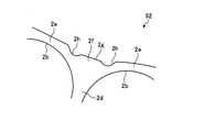
- FIG. FIG. 3 is an enlarged view of the main part of the transverse section showing Embodiment 2 of the magnet-embedded rotor according to the present invention.
- the embedded magnet rotor 92 of the second embodiment is provided with a semicircular recess 2h in the bridge portion 2e on both sides of the protrusion 2f.
- the magnet-embedded rotor 92 of the second embodiment is not different from the magnet-embedded rotor 91 of the first embodiment except that the recessed portion 2h is provided.
- FIG. FIG. 4 is an enlarged view of the essential part of the transverse section showing Embodiment 3 of the magnet-embedded rotor according to the present invention.
- the outer periphery of the rotor core 32 is a perfect circle. Accordingly, the radii from the rotation center O (see FIG. 1) to the outer peripheral portion of the magnetic pole portion 32c, the outer peripheral portion of the bridge portion 32e, and the tip flat surface 32g of the convex portion 32f are all the same.
- a semicircular concave portion 32h is formed in the bridge portion 32e on both sides of the convex portion 32f.
Abstract
La présente invention a trait à un rotor à aimant intégré qui est équipé d'un noyau de fer de rotor (2) qui est formé de manière à se présenter sous une forme cylindrique grâce à la stratification de plaques en acier. Le rotor à aimant intégré comprend une pluralité de trous de logement d'aimant (2b) qui sont disposés de façon annulaire à intervalles prédéterminés sur le bord extérieur, des pôles magnétiques (2c) qui sont formés du côté périphérique extérieur des trous de logement d'aimant (2b), et des nervures (2d) qui sont formées entre les trous de logement d'aimant (2b), adjacentes les unes par rapport aux autres et connectées à des ponts (2e) des deux côtés des pôles magnétiques (2c), et des protubérances (2f) qui font chacune saillie vers l'extérieur à partir d'une connexion entre le pont (2e) et la nervure (2d) et qui sont dotées d'une extrémité avant plate. La largeur dans la direction circonférentielle de la protubérance (2f) est supérieure à la largeur dans la direction circonférentielle de la nervure (2d), et le rayon depuis un centre de rotation (O) jusqu'à l'extrémité avant de la protubérance (2f) est inférieur au rayon depuis le centre de rotation jusqu'à la périphérie extérieure d'une partie centrale du pôle magnétique (2c).
Priority Applications (2)
| Application Number | Priority Date | Filing Date | Title |
|---|---|---|---|
| PCT/JP2012/050402 WO2013105236A1 (fr) | 2012-01-11 | 2012-01-11 | Rotor à aimant intégré |
| TW101124583A TWI495228B (zh) | 2012-01-11 | 2012-07-09 | 磁鐵埋設型轉子 |
Applications Claiming Priority (1)
| Application Number | Priority Date | Filing Date | Title |
|---|---|---|---|
| PCT/JP2012/050402 WO2013105236A1 (fr) | 2012-01-11 | 2012-01-11 | Rotor à aimant intégré |
Publications (1)
| Publication Number | Publication Date |
|---|---|
| WO2013105236A1 true WO2013105236A1 (fr) | 2013-07-18 |
Family
ID=48781209
Family Applications (1)
| Application Number | Title | Priority Date | Filing Date |
|---|---|---|---|
| PCT/JP2012/050402 WO2013105236A1 (fr) | 2012-01-11 | 2012-01-11 | Rotor à aimant intégré |
Country Status (2)
| Country | Link |
|---|---|
| TW (1) | TWI495228B (fr) |
| WO (1) | WO2013105236A1 (fr) |
Cited By (2)
| Publication number | Priority date | Publication date | Assignee | Title |
|---|---|---|---|---|
| WO2017038489A1 (fr) * | 2015-09-01 | 2017-03-09 | 三菱電機株式会社 | Rotor, machine électrique tournante, compresseur électrique, et dispositif de réfrigération/climatiseur |
| US20220190654A1 (en) * | 2020-12-10 | 2022-06-16 | Almott Group Ad | Brushless electrical machine with permanent magnet excitation |
Families Citing this family (1)
| Publication number | Priority date | Publication date | Assignee | Title |
|---|---|---|---|---|
| CN105610257B (zh) * | 2016-03-07 | 2019-11-29 | 广东美芝制冷设备有限公司 | 转子铁芯、转子、电机以及压缩机 |
Citations (9)
| Publication number | Priority date | Publication date | Assignee | Title |
|---|---|---|---|---|
| JP2002165394A (ja) * | 2000-09-13 | 2002-06-07 | Sanyo Denki Co Ltd | 永久磁石内蔵型同期モータ |
| JP2004072845A (ja) * | 2002-08-02 | 2004-03-04 | Aichi Elec Co | 永久磁石電動機 |
| JP2005354798A (ja) * | 2004-06-10 | 2005-12-22 | Fujitsu General Ltd | 電動機 |
| JP2007181346A (ja) * | 2005-12-28 | 2007-07-12 | Fanuc Ltd | 電動機及びそのロータコア並びに電動機を製造する方法 |
| WO2007125753A1 (fr) * | 2006-04-24 | 2007-11-08 | Fujitsu General Limited | Rotor a aimant encastre, moteur utilisant ce rotor, et compresseur utilisant ce moteur |
| JP2009118687A (ja) * | 2007-11-08 | 2009-05-28 | Nissan Motor Co Ltd | 永久磁石式回転機 |
| JP2009278860A (ja) * | 2009-06-26 | 2009-11-26 | Hitachi Ltd | 永久磁石回転電機及びそれを用いた電動車両 |
| JP2011062059A (ja) * | 2009-09-14 | 2011-03-24 | Toyota Industries Corp | 永久磁石埋設型回転電機 |
| JP2011114927A (ja) * | 2009-11-26 | 2011-06-09 | Mitsubishi Electric Corp | 回転子、磁石埋込型電動機、及び、電動圧縮機 |
-
2012
- 2012-01-11 WO PCT/JP2012/050402 patent/WO2013105236A1/fr active Application Filing
- 2012-07-09 TW TW101124583A patent/TWI495228B/zh active
Patent Citations (9)
| Publication number | Priority date | Publication date | Assignee | Title |
|---|---|---|---|---|
| JP2002165394A (ja) * | 2000-09-13 | 2002-06-07 | Sanyo Denki Co Ltd | 永久磁石内蔵型同期モータ |
| JP2004072845A (ja) * | 2002-08-02 | 2004-03-04 | Aichi Elec Co | 永久磁石電動機 |
| JP2005354798A (ja) * | 2004-06-10 | 2005-12-22 | Fujitsu General Ltd | 電動機 |
| JP2007181346A (ja) * | 2005-12-28 | 2007-07-12 | Fanuc Ltd | 電動機及びそのロータコア並びに電動機を製造する方法 |
| WO2007125753A1 (fr) * | 2006-04-24 | 2007-11-08 | Fujitsu General Limited | Rotor a aimant encastre, moteur utilisant ce rotor, et compresseur utilisant ce moteur |
| JP2009118687A (ja) * | 2007-11-08 | 2009-05-28 | Nissan Motor Co Ltd | 永久磁石式回転機 |
| JP2009278860A (ja) * | 2009-06-26 | 2009-11-26 | Hitachi Ltd | 永久磁石回転電機及びそれを用いた電動車両 |
| JP2011062059A (ja) * | 2009-09-14 | 2011-03-24 | Toyota Industries Corp | 永久磁石埋設型回転電機 |
| JP2011114927A (ja) * | 2009-11-26 | 2011-06-09 | Mitsubishi Electric Corp | 回転子、磁石埋込型電動機、及び、電動圧縮機 |
Cited By (5)
| Publication number | Priority date | Publication date | Assignee | Title |
|---|---|---|---|---|
| WO2017038489A1 (fr) * | 2015-09-01 | 2017-03-09 | 三菱電機株式会社 | Rotor, machine électrique tournante, compresseur électrique, et dispositif de réfrigération/climatiseur |
| JPWO2017038489A1 (ja) * | 2015-09-01 | 2018-01-18 | 三菱電機株式会社 | 回転子、回転電機、電動圧縮機および冷凍空調装置 |
| US10594176B2 (en) | 2015-09-01 | 2020-03-17 | Mitsubishi Electric Corporation | Rotor, rotating electric machine, electric compressor, and refrigeration/air-conditioning apparatus |
| US20220190654A1 (en) * | 2020-12-10 | 2022-06-16 | Almott Group Ad | Brushless electrical machine with permanent magnet excitation |
| US11804740B2 (en) * | 2020-12-10 | 2023-10-31 | Almott Group Ad | Brushless electrical machine with permanent magnet excitation |
Also Published As
| Publication number | Publication date |
|---|---|
| TW201330459A (zh) | 2013-07-16 |
| TWI495228B (zh) | 2015-08-01 |
Similar Documents
| Publication | Publication Date | Title |
|---|---|---|
| JP5321451B2 (ja) | 永久磁石埋設型電動機 | |
| US9130441B2 (en) | Brushless DC motor | |
| JP5353917B2 (ja) | 回転電機用回転子 | |
| JP4110146B2 (ja) | 磁性体、回転子、電動機 | |
| JP6274475B2 (ja) | 回転子、回転電機および回転子の製造方法 | |
| US11038388B2 (en) | Rotor of rotary electric machine | |
| KR100624381B1 (ko) | 영구자석 매립형 전동기의 회전자와 그 제조방법 | |
| WO2014091579A1 (fr) | Rotor pour moteur | |
| JP5298402B2 (ja) | モータのエンドプレート構造 | |
| CN105518976A (zh) | 永磁体式旋转电机的转子 | |
| US9570947B2 (en) | Electric rotating machine | |
| WO2017195498A1 (fr) | Rotor et machine électrique rotative | |
| WO2013105236A1 (fr) | Rotor à aimant intégré | |
| JP4291211B2 (ja) | 回転電機の回転子および回転電機 | |
| US11139705B2 (en) | Electric motor | |
| KR101867973B1 (ko) | 모터의 로터 및 이를 갖는 모터 | |
| JP2011172359A (ja) | 分割型回転子及び電動機 | |
| JP2018023232A (ja) | 回転電機および回転電機の製造方法 | |
| JPWO2013105236A1 (ja) | 磁石埋込型回転子 | |
| JP2015056911A (ja) | ロータ及びこのロータを備える回転電機 | |
| JP5879848B2 (ja) | 埋込磁石形回転電機のロータ | |
| JP2015082862A (ja) | 回転電機のロータコアとシャフトの締結構造 | |
| KR20190031763A (ko) | 모터 | |
| JP6337549B2 (ja) | 磁石埋込型ロータ | |
| JP7113906B2 (ja) | 回転電機 |
Legal Events
| Date | Code | Title | Description |
|---|---|---|---|
| ENP | Entry into the national phase |
Ref document number: 2012530021 Country of ref document: JP Kind code of ref document: A |
|
| 121 | Ep: the epo has been informed by wipo that ep was designated in this application |
Ref document number: 12865391 Country of ref document: EP Kind code of ref document: A1 |
|
| NENP | Non-entry into the national phase |
Ref country code: DE |
|
| 122 | Ep: pct application non-entry in european phase |
Ref document number: 12865391 Country of ref document: EP Kind code of ref document: A1 |