WO2013105236A1 - Embedded magnet rotor - Google Patents
Embedded magnet rotor Download PDFInfo
- Publication number
- WO2013105236A1 WO2013105236A1 PCT/JP2012/050402 JP2012050402W WO2013105236A1 WO 2013105236 A1 WO2013105236 A1 WO 2013105236A1 JP 2012050402 W JP2012050402 W JP 2012050402W WO 2013105236 A1 WO2013105236 A1 WO 2013105236A1
- Authority
- WO
- WIPO (PCT)
- Prior art keywords
- magnet
- magnetic pole
- embedded
- radius
- bridge
- Prior art date
Links
Images


Classifications
-
- H—ELECTRICITY
- H02—GENERATION; CONVERSION OR DISTRIBUTION OF ELECTRIC POWER
- H02K—DYNAMO-ELECTRIC MACHINES
- H02K1/00—Details of the magnetic circuit
- H02K1/06—Details of the magnetic circuit characterised by the shape, form or construction
- H02K1/22—Rotating parts of the magnetic circuit
- H02K1/27—Rotor cores with permanent magnets
- H02K1/2706—Inner rotors
- H02K1/272—Inner rotors the magnetisation axis of the magnets being perpendicular to the rotor axis
- H02K1/274—Inner rotors the magnetisation axis of the magnets being perpendicular to the rotor axis the rotor consisting of two or more circumferentially positioned magnets
- H02K1/2753—Inner rotors the magnetisation axis of the magnets being perpendicular to the rotor axis the rotor consisting of two or more circumferentially positioned magnets the rotor consisting of magnets or groups of magnets arranged with alternating polarity
- H02K1/276—Magnets embedded in the magnetic core, e.g. interior permanent magnets [IPM]
-
- H—ELECTRICITY
- H02—GENERATION; CONVERSION OR DISTRIBUTION OF ELECTRIC POWER
- H02K—DYNAMO-ELECTRIC MACHINES
- H02K2213/00—Specific aspects, not otherwise provided for and not covered by codes H02K2201/00 - H02K2211/00
- H02K2213/03—Machines characterised by numerical values, ranges, mathematical expressions or similar information
-
- H—ELECTRICITY
- H02—GENERATION; CONVERSION OR DISTRIBUTION OF ELECTRIC POWER
- H02K—DYNAMO-ELECTRIC MACHINES
- H02K29/00—Motors or generators having non-mechanical commutating devices, e.g. discharge tubes or semiconductor devices
- H02K29/03—Motors or generators having non-mechanical commutating devices, e.g. discharge tubes or semiconductor devices with a magnetic circuit specially adapted for avoiding torque ripples or self-starting problems
Definitions
- the present invention relates to a magnet embedded rotor in which a permanent magnet is embedded in a rotor core.
- a rotor core in which flat magnet permanent magnets are embedded at predetermined intervals in an annular manner on an outer edge, and adjacent to a magnetic pole part formed on the outer peripheral side of the magnet embedded hole.
- a magnet-embedded rotor having a small-diameter portion that is formed on the outer peripheral portion between the matching magnetic pole portions and has a smaller radius from the rotation center than the magnetic pole portion (see, for example, Patent Document 1). .
- a rotor core connecting portion (thin wall portion) for preventing magnet scattering is provided between the outer peripheral end of the magnet embedding hole and the outer peripheral end of the rotor, and a rectangular notch is formed in the rotor core connecting portion.
- the circumferential length of the notch portion is the outer circumference side end of the magnet embedding hole at the portion where the notch portion is located and the outer circumference of the other magnet embedding hole nearest to the magnet embedding hole.
- the outer peripheral surface of the rotor is a curved surface. Therefore, when chucking the outer peripheral surface and press-fitting a rotary shaft or the like, the chuck, the outer peripheral surface, Is point contact, and the chuck is liable to be displaced. Therefore, there is a problem that an excessive chucking force is applied to the thin portion between the magnet insertion hole and the outer peripheral surface of the rotor, and the thin portion is deformed.
- the rectangular cutout portion can be chucked.
- the magnet insertion hole and the cutout portion There is a problem that a chucking force is applied to the thin-walled portion between the two and the thin-walled portion is deformed similarly to the above.
- the present invention has been made in view of the above, and it is an object of the present invention to obtain a magnet embedded rotor in which the chuck position is difficult to shift and the thin portion between the magnet embedded hole and the outer peripheral surface is not deformed. Objective.
- the present invention provides a plurality of magnet embedding holes formed in a cylindrical shape by laminating steel plates, and arranged annularly at predetermined intervals on the outer edge portion, and the magnet A magnetic pole part formed on the outer peripheral side of the embedded hole, a rib part formed between adjacent magnet embedded holes and connected to the bridge parts on both sides of the magnetic pole part, and a connecting part between the bridge part and the rib part And a rotor core having a convex portion protruding outward and having a flat tip.
- the chuck and the tip of the convex portion are in surface contact with each other, so that the chuck position is difficult to shift. Since it protrudes outward from the connection part of the rib part, there is an effect that the compressive force of the chuck is transmitted from the convex part to the rib part and the thin bridge part is not deformed.
- FIG. 1 is a cross-sectional view showing a first embodiment of a magnet-embedded rotor according to the present invention.
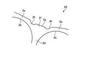
- FIG. 2 is an enlarged view of part A in FIG.
- FIG. 3 is an enlarged view of the main part of the transverse section showing Embodiment 2 of the magnet-embedded rotor according to the present invention.
- FIG. 4 is an enlarged view of the main part of the transverse section showing Embodiment 3 of the magnet-embedded rotor according to the present invention.
- FIG. 1 is a cross-sectional view showing a first embodiment of a magnet-embedded rotor according to the present invention
- FIG. 2 is an enlarged view of a portion A in FIG.
- the rotor core 2 of the magnet-embedded rotor 91 is formed in a cylindrical shape by laminating a number of thin silicon steel plates (magnetic bodies), and is integrated by a rivet (not shown). ing.
- a shaft 4 is press-fitted and fixed in a shaft hole 2 a formed at the center of the rotor core 2.
- Magnet embedding holes that are arranged annularly at predetermined intervals on the outer edge of the rotor core 2 so that ten flat permanent magnets 3 form each side of a regular decagon centered on the rotation center O. Embedded in 2b. A magnetic pole portion 2 c is formed on the outer peripheral side of the magnet embedded hole 2 b of the rotor core 2.
- a rib portion 2d is formed between two adjacent magnet embedding holes 2b. Thin bridge portions 2e on both sides of the magnetic pole portion 2c are connected to the rib portion 2d. A radius Re from the rotation center O to the outer periphery of the bridge portion 2e is smaller than a radius Rc from the magnetic pole portion 2c to the outer periphery of the central portion.
- the outer periphery of the magnetic pole part 2c has a curved shape, and the shape between the adjacent magnetic pole parts 2c is recessed compared to the center of the magnetic pole part 2c. This is because by curving the magnetic pole portion 2c, the harmonic component of the magnetic flux interlinking with a stator winding (not shown) is reduced, and the induced voltage is brought close to a sine wave.
- the bridge portion 2e is preferably formed to have a radial width as narrow as possible (for example, a thickness of a silicon steel plate or less) within a range that does not hinder processing so that magnetic saturation is difficult and magnetic flux does not easily pass.
- the convex part 2f protrudes outward from the connection part of the bridge part 2e and the rib part.
- the tip of the convex portion 2f is a tip flat surface 2g orthogonal to a meridian S passing through the center of rotation O and the center of the rib portion 2d.
- a radius Rg from the rotation center O to the tip plane 2g is smaller than a radius Rc from the magnetic pole part 2c to the outer periphery of the central part.
- the tip flat surface 2g of the projecting portion 2f facing the rotation center O is chucked. Since the tip flat surface 2g is in surface contact with a chuck surface of a chuck (not shown), the rotor core 2 is not detached from the chuck even if a rotational force or the like acts on the rotor core 2.
- the circumferential width Hg of the tip flat surface 2g of the convex portion 2f is made larger than the width Hd of the rib portion 2d. This prevents the convex portion 2f from buckling before the rib portion 2d. Further, if the circumferential width Hg of the tip flat surface 2g of the convex portion 2f is small, the convex portion 2f is deformed by the compressive force of the chuck, and non-uniform stress such as torsional stress is generated in the rotor core 2. The generation of uneven stress is prevented by increasing the width Hg.
- FIG. FIG. 3 is an enlarged view of the main part of the transverse section showing Embodiment 2 of the magnet-embedded rotor according to the present invention.
- the embedded magnet rotor 92 of the second embodiment is provided with a semicircular recess 2h in the bridge portion 2e on both sides of the protrusion 2f.
- the magnet-embedded rotor 92 of the second embodiment is not different from the magnet-embedded rotor 91 of the first embodiment except that the recessed portion 2h is provided.
- FIG. FIG. 4 is an enlarged view of the essential part of the transverse section showing Embodiment 3 of the magnet-embedded rotor according to the present invention.
- the outer periphery of the rotor core 32 is a perfect circle. Accordingly, the radii from the rotation center O (see FIG. 1) to the outer peripheral portion of the magnetic pole portion 32c, the outer peripheral portion of the bridge portion 32e, and the tip flat surface 32g of the convex portion 32f are all the same.
- a semicircular concave portion 32h is formed in the bridge portion 32e on both sides of the convex portion 32f.
Abstract
An embedded magnet rotor is provided with a rotor iron core (2) formed into a cylindrical shape by laminating steel plates, and comprising a plurality of magnet embedding holes (2b) annularly disposed at predetermined intervals at the outer edge, magnetic poles (2c) formed at the outer peripheral side of the magnet embedding holes (2b), and ribs (2d) formed between the magnet embedding holes (2b) adjacent to each other, and connected to bridges (2e) on both sides of the magnetic poles (2c), and protrusions (2f) each protrude outward from a connection between the bridge (2e) and the rib (2d) and having a flat leading end. The width in the circumferential direction of the protrusion (2f) is made larger than the width in the circumferential direction of the rib (2d), and a radius from a rotation center (O) to the leading end of the protrusion (2f) is smaller than a radius from the rotation center to the outer periphery of a central portion of the magnetic pole (2c).
Description
本発明は、回転子鉄心に永久磁石を埋め込んだ磁石埋込型回転子に関する。
The present invention relates to a magnet embedded rotor in which a permanent magnet is embedded in a rotor core.
従来、平板状の永久磁石が埋め込まれる磁石埋込孔を、外縁部に環状に所定間隔で配置した回転子鉄心であって、前記磁石埋込孔の外周側に形成された磁極部と、隣合う前記磁極部の間の外周部に形成され、前記磁極部よりも回転中心からの半径が小さい小径部と、を有する磁石埋込型回転子が開示されている(例えば、特許文献1参照)。
2. Description of the Related Art Conventionally, a rotor core in which flat magnet permanent magnets are embedded at predetermined intervals in an annular manner on an outer edge, and adjacent to a magnetic pole part formed on the outer peripheral side of the magnet embedded hole. There is disclosed a magnet-embedded rotor having a small-diameter portion that is formed on the outer peripheral portion between the matching magnetic pole portions and has a smaller radius from the rotation center than the magnetic pole portion (see, for example, Patent Document 1). .
また、1磁極につき略V字形状のように半径方向内側に向けて互いに次第に間隔の狭くなるように設けた2個の磁石埋込孔から成る磁石埋込孔対を複数対有する回転子において、前記磁石埋込孔の外周側端部と前記回転子外周端との間に磁石飛散防止用の回転子鉄心連結部(薄肉部)を設け、かつ該回転子鉄心連結部に矩形の切り欠き部を設け、前記切り欠き部の周方向長さは、該切り欠き部のある部位の磁石埋込孔の外周側端部と該磁石埋込孔に隣接する直近の他の磁石埋込孔の外周側端部との間の互いに遠い方の内壁同士を結ぶ距離より短くなっている磁石埋込型回転子が開示されている(例えば、特許文献2参照)。
Further, in a rotor having a plurality of pairs of magnet embedding holes composed of two magnet embedding holes provided so as to be gradually narrower from each other toward the inside in the radial direction as in a substantially V shape per magnetic pole, A rotor core connecting portion (thin wall portion) for preventing magnet scattering is provided between the outer peripheral end of the magnet embedding hole and the outer peripheral end of the rotor, and a rectangular notch is formed in the rotor core connecting portion. The circumferential length of the notch portion is the outer circumference side end of the magnet embedding hole at the portion where the notch portion is located and the outer circumference of the other magnet embedding hole nearest to the magnet embedding hole. There is disclosed a magnet-embedded rotor that is shorter than the distance between inner walls that are far from each other between the side ends (see, for example, Patent Document 2).
しかしながら、上記特許文献1に開示された従来の技術によれば、回転子の外周面が曲面になっているので、外周面をチャックして回転軸等を圧入するときに、チャックと外周面とが点接触となり、チャックの位置ずれが起こりやすい。そのため、磁石挿入孔と回転子の外周面との間の薄肉部に、過大なチャッキング力が加わり、薄肉部が変形してしまう、という問題があった。
However, according to the conventional technique disclosed in Patent Document 1, the outer peripheral surface of the rotor is a curved surface. Therefore, when chucking the outer peripheral surface and press-fitting a rotary shaft or the like, the chuck, the outer peripheral surface, Is point contact, and the chuck is liable to be displaced. Therefore, there is a problem that an excessive chucking force is applied to the thin portion between the magnet insertion hole and the outer peripheral surface of the rotor, and the thin portion is deformed.
また、上記特許文献2に開示された従来の技術によれば、矩形の切り欠き部をチャックすることができるが、切り欠き部のチャック位置が左右にずれると、磁石挿入孔と切り欠き部との間の薄肉部にチャッキング力が加わり、上記と同様に、薄肉部が変形してしまう、という問題がある。
Further, according to the conventional technique disclosed in Patent Document 2, the rectangular cutout portion can be chucked. However, when the chuck position of the cutout portion is shifted to the left and right, the magnet insertion hole and the cutout portion There is a problem that a chucking force is applied to the thin-walled portion between the two and the thin-walled portion is deformed similarly to the above.
本発明は、上記に鑑みてなされたものであって、チャック位置がずれ難く、磁石埋込孔と外周面との間の薄肉部が変形することのない磁石埋込型回転子を得ることを目的とする。
The present invention has been made in view of the above, and it is an object of the present invention to obtain a magnet embedded rotor in which the chuck position is difficult to shift and the thin portion between the magnet embedded hole and the outer peripheral surface is not deformed. Objective.
上述した課題を解決し、目的を達成するために、本発明は、鋼板を積層して円柱状に形成され、外縁部に環状に所定間隔で配置された複数の磁石埋込孔と、前記磁石埋込孔の外周側に形成された磁極部と、隣り合う前記磁石埋込孔間に形成され、前記磁極部の両側のブリッジ部と接続するリブ部と、前記ブリッジ部とリブ部の接続部から外方に突出し先端が平らな凸部と、を有する回転子鉄心を備えることを特徴とする。
In order to solve the above-described problems and achieve the object, the present invention provides a plurality of magnet embedding holes formed in a cylindrical shape by laminating steel plates, and arranged annularly at predetermined intervals on the outer edge portion, and the magnet A magnetic pole part formed on the outer peripheral side of the embedded hole, a rib part formed between adjacent magnet embedded holes and connected to the bridge parts on both sides of the magnetic pole part, and a connecting part between the bridge part and the rib part And a rotor core having a convex portion protruding outward and having a flat tip.
本発明にかかる磁石埋込型回転子は、先端が平らな凸部をチャックすれば、チャックと凸部の先端が面接触するので、チャック位置がずれ難く、また、凸部は、ブリッジ部とリブ部の接続部から外方に突出しているので、チャックの圧縮力が凸部からリブ部に伝わり、薄肉のブリッジ部が変形することはない、という効果を奏する。
In the magnet-embedded rotor according to the present invention, if the convex portion with a flat tip is chucked, the chuck and the tip of the convex portion are in surface contact with each other, so that the chuck position is difficult to shift. Since it protrudes outward from the connection part of the rib part, there is an effect that the compressive force of the chuck is transmitted from the convex part to the rib part and the thin bridge part is not deformed.
以下に、本発明にかかる磁石埋込型回転子の実施の形態を図面に基づいて詳細に説明する。なお、この実施の形態によりこの発明が限定されるものではない。
Hereinafter, an embodiment of an embedded magnet rotor according to the present invention will be described in detail with reference to the drawings. Note that the present invention is not limited to the embodiments.
実施の形態1.
図1は、本発明に係る磁石埋込型回転子の実施の形態1を示す横断面図であり、図2は、図1のA部拡大図である。 Embodiment 1 FIG.
FIG. 1 is a cross-sectional view showing a first embodiment of a magnet-embedded rotor according to the present invention, and FIG. 2 is an enlarged view of a portion A in FIG.
図1は、本発明に係る磁石埋込型回転子の実施の形態1を示す横断面図であり、図2は、図1のA部拡大図である。 Embodiment 1 FIG.
FIG. 1 is a cross-sectional view showing a first embodiment of a magnet-embedded rotor according to the present invention, and FIG. 2 is an enlarged view of a portion A in FIG.
図1及び図2に示すように、磁石埋込型回転子91の回転子鉄心2は、薄い珪素鋼板(磁性体)を多数積層して円柱状に形成され、図示しないリベット等により一体化されている。回転子鉄心2の中心に形成された軸孔2aには、シャフト4が圧入され固定される。
As shown in FIGS. 1 and 2, the rotor core 2 of the magnet-embedded rotor 91 is formed in a cylindrical shape by laminating a number of thin silicon steel plates (magnetic bodies), and is integrated by a rivet (not shown). ing. A shaft 4 is press-fitted and fixed in a shaft hole 2 a formed at the center of the rotor core 2.
10枚の平板状の永久磁石3が、回転中心Oを中心とする正10角形の各辺を成すように、回転子鉄心2の外縁部に、環状に所定間隔で配置された磁石埋込孔2bに埋め込まれる。回転子鉄心2の磁石埋込孔2bの外周側には、磁極部2cが形成されている。
Magnet embedding holes that are arranged annularly at predetermined intervals on the outer edge of the rotor core 2 so that ten flat permanent magnets 3 form each side of a regular decagon centered on the rotation center O. Embedded in 2b. A magnetic pole portion 2 c is formed on the outer peripheral side of the magnet embedded hole 2 b of the rotor core 2.
隣り合う2つの磁石埋込孔2b間には、リブ部2dが形成されている。磁極部2cの両側の薄肉のブリッジ部2eは、リブ部2dに接続している。回転中心Oからブリッジ部2eの外周までの半径Reは、磁極部2c中央部外周までの半径Rcより小さくされている。
A rib portion 2d is formed between two adjacent magnet embedding holes 2b. Thin bridge portions 2e on both sides of the magnetic pole portion 2c are connected to the rib portion 2d. A radius Re from the rotation center O to the outer periphery of the bridge portion 2e is smaller than a radius Rc from the magnetic pole portion 2c to the outer periphery of the central portion.
すなわち、磁極部2cの外周は湾曲形状となっていて、磁極部2c中央に比べ隣り合う磁極部2c間が凹んだ形状となっている。これは、磁極部2cを湾曲させることにより、図示しない固定子巻線に鎖交する磁束の高調波成分を低減し、誘起電圧を正弦波に近づけるためである。
That is, the outer periphery of the magnetic pole part 2c has a curved shape, and the shape between the adjacent magnetic pole parts 2c is recessed compared to the center of the magnetic pole part 2c. This is because by curving the magnetic pole portion 2c, the harmonic component of the magnetic flux interlinking with a stator winding (not shown) is reduced, and the induced voltage is brought close to a sine wave.
ブリッジ部2eは、磁気飽和して磁束が通過し難くなるように、加工に支障のない範囲で、可能な限り狭い径方向の幅(例えば、珪素鋼板の板厚以下)に形成するとよい。
The bridge portion 2e is preferably formed to have a radial width as narrow as possible (for example, a thickness of a silicon steel plate or less) within a range that does not hinder processing so that magnetic saturation is difficult and magnetic flux does not easily pass.
ブリッジ部2eとリブ部の接続部から外方に凸部2fが突出している。凸部2fの先端は、回転中心O及びリブ部2d中心を通る経線Sに直交する先端平面2gとなっている。回転中心Oから先端平面2gまでの半径Rgは、磁極部2c中央部外周までの半径Rcより小さくなっている。
The convex part 2f protrudes outward from the connection part of the bridge part 2e and the rib part. The tip of the convex portion 2f is a tip flat surface 2g orthogonal to a meridian S passing through the center of rotation O and the center of the rib portion 2d. A radius Rg from the rotation center O to the tip plane 2g is smaller than a radius Rc from the magnetic pole part 2c to the outer periphery of the central part.
磁石埋込型回転子91の製造工程の中で、回転子鉄心2をチャックするときは、回転中心Oを挟んで対向する凸部2fの先端平面2gをチャックするようにする。先端平面2gは、図示しないチャックのチャック面と面接触するので、回転子鉄心2に回転力等が作用しても、回転子鉄心2がチャックから外れることはない。
When the rotor core 2 is chucked during the manufacturing process of the magnet-embedded rotor 91, the tip flat surface 2g of the projecting portion 2f facing the rotation center O is chucked. Since the tip flat surface 2g is in surface contact with a chuck surface of a chuck (not shown), the rotor core 2 is not detached from the chuck even if a rotational force or the like acts on the rotor core 2.
また、凸部2fの先端平面2gをチャックすると、その圧縮力はリブ部2dに直接伝わるので、ブリッジ部2eに応力は発生せず、リブ部2dに曲げ応力が発生することもなく、ブリッジ部2eが変形することもない。また、万が一、チャックが凸部2fの中央からずれても、ブリッジ部2eに接触することはなく、ブリッジ部2eを変形させることもない。
Further, when the tip flat surface 2g of the convex portion 2f is chucked, the compressive force is directly transmitted to the rib portion 2d. Therefore, no stress is generated in the bridge portion 2e, and no bending stress is generated in the rib portion 2d. 2e is not deformed. Also, even if the chuck is displaced from the center of the convex portion 2f, the bridge portion 2e is not contacted and the bridge portion 2e is not deformed.
図2に示すように、凸部2fの先端平面2gの周方向の幅Hgを、リブ部2dの幅Hdより大きくしている。これにより、凸部2fがリブ部2dより先に座屈するのを防止している。また、凸部2fの先端平面2gの周方向の幅Hgが小さいと、チャックの圧縮力により凸部2fが変形し、回転子鉄心2に捻じり応力等の不均一な応力が発生するが、幅Hgを大きくして不均一な応力の発生を防止している。
As shown in FIG. 2, the circumferential width Hg of the tip flat surface 2g of the convex portion 2f is made larger than the width Hd of the rib portion 2d. This prevents the convex portion 2f from buckling before the rib portion 2d. Further, if the circumferential width Hg of the tip flat surface 2g of the convex portion 2f is small, the convex portion 2f is deformed by the compressive force of the chuck, and non-uniform stress such as torsional stress is generated in the rotor core 2. The generation of uneven stress is prevented by increasing the width Hg.
ただし、凸部2fの先端平面2gの周方向の幅Hgを大きくし過ぎると、固定子の巻線に鎖交する磁束の高調波成分が増加し、誘起電圧にも高調波成分が重畳するため、注意が必要である。固定子と凸部2fの先端平面2gとのギャップを、固定子と磁極部2cとののギャップの2倍程度にすれば、凸部2fにより磁束の高調波成分が増加することはない。
However, if the circumferential width Hg of the tip flat surface 2g of the convex portion 2f is excessively increased, the harmonic component of the magnetic flux interlinking with the stator winding increases, and the harmonic component is also superimposed on the induced voltage. ,Caution must be taken. If the gap between the stator and the tip flat surface 2g of the convex portion 2f is about twice the gap between the stator and the magnetic pole portion 2c, the harmonic component of the magnetic flux will not increase due to the convex portion 2f.
実施の形態2.
図3は、本発明に係る磁石埋込型回転子の実施の形態2を示す横断面要部拡大図である。図3に示すように、実施の形態2の磁石埋込型回転子92は、凸部2fの両側のブリッジ部2eに、半円状の凹部2hを設けている。実施の形態2の磁石埋込型回転子92は、凹部2hを設けたこと以外は、実施の形態1の磁石埋込型回転子91と異なるところはない。Embodiment 2. FIG.
FIG. 3 is an enlarged view of the main part of the transversesection showing Embodiment 2 of the magnet-embedded rotor according to the present invention. As shown in FIG. 3, the embedded magnet rotor 92 of the second embodiment is provided with a semicircular recess 2h in the bridge portion 2e on both sides of the protrusion 2f. The magnet-embedded rotor 92 of the second embodiment is not different from the magnet-embedded rotor 91 of the first embodiment except that the recessed portion 2h is provided.
図3は、本発明に係る磁石埋込型回転子の実施の形態2を示す横断面要部拡大図である。図3に示すように、実施の形態2の磁石埋込型回転子92は、凸部2fの両側のブリッジ部2eに、半円状の凹部2hを設けている。実施の形態2の磁石埋込型回転子92は、凹部2hを設けたこと以外は、実施の形態1の磁石埋込型回転子91と異なるところはない。
FIG. 3 is an enlarged view of the main part of the transverse
凸部2fの両側のブリッジ部2eに半円状の凹部2hを設けることにより、凸部2fにより発生する誘起電圧の高調波成分の重畳を防ぐことができる。凹部2hを半円状とすることにより、凸部2fに作用する圧縮力による応力集中を緩和することができる。
By providing the semicircular concave portions 2h on the bridge portions 2e on both sides of the convex portion 2f, it is possible to prevent superposition of harmonic components of the induced voltage generated by the convex portions 2f. By making the concave portion 2h semicircular, stress concentration due to compressive force acting on the convex portion 2f can be reduced.
実施の形態3.
図4は、本発明に係る磁石埋込型回転子の実施の形態3を示す横断面要部拡大図である。実施の形態3の磁石埋込型回転子93は、回転子鉄心32の外周部が真円となっている。従って、回転中心O(図1参照)から、磁極部32cの外周部、ブリッジ部32eの外周部及び凸部32fの先端平面32gまでの半径は、全て同一となっている。凸部32fを形成するために、凸部32fの両側のブリッジ部32eに半円状の凹部32hを形成している。Embodiment 3 FIG.
FIG. 4 is an enlarged view of the essential part of the transversesection showing Embodiment 3 of the magnet-embedded rotor according to the present invention. In the magnet embedded rotor 93 of the third embodiment, the outer periphery of the rotor core 32 is a perfect circle. Accordingly, the radii from the rotation center O (see FIG. 1) to the outer peripheral portion of the magnetic pole portion 32c, the outer peripheral portion of the bridge portion 32e, and the tip flat surface 32g of the convex portion 32f are all the same. In order to form the convex portion 32f, a semicircular concave portion 32h is formed in the bridge portion 32e on both sides of the convex portion 32f.
図4は、本発明に係る磁石埋込型回転子の実施の形態3を示す横断面要部拡大図である。実施の形態3の磁石埋込型回転子93は、回転子鉄心32の外周部が真円となっている。従って、回転中心O(図1参照)から、磁極部32cの外周部、ブリッジ部32eの外周部及び凸部32fの先端平面32gまでの半径は、全て同一となっている。凸部32fを形成するために、凸部32fの両側のブリッジ部32eに半円状の凹部32hを形成している。
FIG. 4 is an enlarged view of the essential part of the transverse
2 回転子鉄心
2a 軸孔
2b 磁石埋込孔
2c、32c 磁極部
2d リブ部
2e、32e ブリッジ部
2f、32f 凸部
2g、32g 先端平面
2h、32h 凹部
3 永久磁石
4 シャフト
91、92,93 磁石埋込型回転子
O 回転中心
S 経線 2Rotor core 2a Shaft hole 2b Magnet embedded hole 2c, 32c Magnetic pole part 2d Rib part 2e, 32e Bridge part 2f, 32f Protrusion part 2g, 32g Tip plane 2h, 32h Concavity 3 Permanent magnet 4 Shaft 91, 92, 93 Magnet Embedded rotor O Center of rotation S Meridian
2a 軸孔
2b 磁石埋込孔
2c、32c 磁極部
2d リブ部
2e、32e ブリッジ部
2f、32f 凸部
2g、32g 先端平面
2h、32h 凹部
3 永久磁石
4 シャフト
91、92,93 磁石埋込型回転子
O 回転中心
S 経線 2
Claims (6)
- 鋼板を積層して円柱状に形成され、
外縁部に環状に所定間隔で配置された複数の磁石埋込孔と、
前記磁石埋込孔の外周側に形成された磁極部と、
隣り合う前記磁石埋込孔間に形成され、前記磁極部の両側のブリッジ部と接続するリブ部と、
前記ブリッジ部とリブ部の接続部から外方に突出し先端が平らな凸部と、
を有する回転子鉄心を備えることを特徴とする磁石埋込型回転子。 It is formed in a cylindrical shape by laminating steel plates,
A plurality of magnet embedding holes arranged annularly at a predetermined interval on the outer edge, and
A magnetic pole portion formed on the outer peripheral side of the magnet embedding hole;
Rib portions formed between adjacent magnet embedding holes and connected to bridge portions on both sides of the magnetic pole portion;
A convex part that protrudes outward from the connecting part of the bridge part and the rib part and has a flat tip,
A rotor with an embedded magnet is provided. - 前記凸部の周方向幅を前記リブ部の周方向幅より大きくしたことを特徴とする請求項1に記載の磁石埋込型回転子。 2. The embedded magnet rotor according to claim 1, wherein a circumferential width of the convex portion is larger than a circumferential width of the rib portion.
- 回転中心から前記凸部の先端までの半径は、回転中心から前記磁極部の中央部の外周までの半径よりも小さいことを特徴とする請求項1に記載の磁石埋込型回転子。 The embedded magnet type rotor according to claim 1, wherein the radius from the rotation center to the tip of the convex portion is smaller than the radius from the rotation center to the outer periphery of the central portion of the magnetic pole portion.
- 前記凸部の両側のブリッジ部に、半円状の凹部が形成されていることを特徴とする請求項1に記載の磁石埋込型回転子。 2. The embedded magnet rotor according to claim 1, wherein a semicircular concave portion is formed in a bridge portion on both sides of the convex portion.
- 回転中心から前記凸部の先端までの半径は、回転中心から前記磁極部の中央部の外周までの半径と同一であることを特徴とする請求項4に記載の磁石埋込型回転子。 5. The embedded magnet rotor according to claim 4, wherein the radius from the rotation center to the tip of the convex portion is the same as the radius from the rotation center to the outer periphery of the central portion of the magnetic pole portion.
- 前記ブリッジ部の径方向の幅が、前記鋼板の板厚以下であることを特徴とする請求項1に記載の磁石埋込型回転子。 The embedded magnet type rotor according to claim 1, wherein a radial width of the bridge portion is equal to or less than a plate thickness of the steel plate.
Priority Applications (2)
| Application Number | Priority Date | Filing Date | Title |
|---|---|---|---|
| PCT/JP2012/050402 WO2013105236A1 (en) | 2012-01-11 | 2012-01-11 | Embedded magnet rotor |
| TW101124583A TWI495228B (en) | 2012-01-11 | 2012-07-09 | Magnet piece embedded type rotor |
Applications Claiming Priority (1)
| Application Number | Priority Date | Filing Date | Title |
|---|---|---|---|
| PCT/JP2012/050402 WO2013105236A1 (en) | 2012-01-11 | 2012-01-11 | Embedded magnet rotor |
Publications (1)
| Publication Number | Publication Date |
|---|---|
| WO2013105236A1 true WO2013105236A1 (en) | 2013-07-18 |
Family
ID=48781209
Family Applications (1)
| Application Number | Title | Priority Date | Filing Date |
|---|---|---|---|
| PCT/JP2012/050402 WO2013105236A1 (en) | 2012-01-11 | 2012-01-11 | Embedded magnet rotor |
Country Status (2)
| Country | Link |
|---|---|
| TW (1) | TWI495228B (en) |
| WO (1) | WO2013105236A1 (en) |
Cited By (2)
| Publication number | Priority date | Publication date | Assignee | Title |
|---|---|---|---|---|
| WO2017038489A1 (en) * | 2015-09-01 | 2017-03-09 | 三菱電機株式会社 | Rotor, rotating electric machine, electric compressor, and refrigeration/air-conditioning device |
| US20220190654A1 (en) * | 2020-12-10 | 2022-06-16 | Almott Group Ad | Brushless electrical machine with permanent magnet excitation |
Families Citing this family (1)
| Publication number | Priority date | Publication date | Assignee | Title |
|---|---|---|---|---|
| CN105610257B (en) * | 2016-03-07 | 2019-11-29 | 广东美芝制冷设备有限公司 | Rotor core, rotor, motor and compressor |
Citations (9)
| Publication number | Priority date | Publication date | Assignee | Title |
|---|---|---|---|---|
| JP2002165394A (en) * | 2000-09-13 | 2002-06-07 | Sanyo Denki Co Ltd | Synchronous motor with built-in permanent magnet |
| JP2004072845A (en) * | 2002-08-02 | 2004-03-04 | Aichi Elec Co | Permanent magnetic motor |
| JP2005354798A (en) * | 2004-06-10 | 2005-12-22 | Fujitsu General Ltd | Electric motor |
| JP2007181346A (en) * | 2005-12-28 | 2007-07-12 | Fanuc Ltd | Motor and rotor core thereof, and method for manufacturing electric motor |
| WO2007125753A1 (en) * | 2006-04-24 | 2007-11-08 | Fujitsu General Limited | Buried magnet rotor, motor using this rotor, and compressor using this motor |
| JP2009118687A (en) * | 2007-11-08 | 2009-05-28 | Nissan Motor Co Ltd | Permanent magnet type rotating machine |
| JP2009278860A (en) * | 2009-06-26 | 2009-11-26 | Hitachi Ltd | Permanent magnet rotating electric machine and electric vehicle using the same |
| JP2011062059A (en) * | 2009-09-14 | 2011-03-24 | Toyota Industries Corp | Permanent magnet embedded rotating electrical machine |
| JP2011114927A (en) * | 2009-11-26 | 2011-06-09 | Mitsubishi Electric Corp | Rotor, magnet embedded electric motor, and electric compressor |
-
2012
- 2012-01-11 WO PCT/JP2012/050402 patent/WO2013105236A1/en active Application Filing
- 2012-07-09 TW TW101124583A patent/TWI495228B/en active
Patent Citations (9)
| Publication number | Priority date | Publication date | Assignee | Title |
|---|---|---|---|---|
| JP2002165394A (en) * | 2000-09-13 | 2002-06-07 | Sanyo Denki Co Ltd | Synchronous motor with built-in permanent magnet |
| JP2004072845A (en) * | 2002-08-02 | 2004-03-04 | Aichi Elec Co | Permanent magnetic motor |
| JP2005354798A (en) * | 2004-06-10 | 2005-12-22 | Fujitsu General Ltd | Electric motor |
| JP2007181346A (en) * | 2005-12-28 | 2007-07-12 | Fanuc Ltd | Motor and rotor core thereof, and method for manufacturing electric motor |
| WO2007125753A1 (en) * | 2006-04-24 | 2007-11-08 | Fujitsu General Limited | Buried magnet rotor, motor using this rotor, and compressor using this motor |
| JP2009118687A (en) * | 2007-11-08 | 2009-05-28 | Nissan Motor Co Ltd | Permanent magnet type rotating machine |
| JP2009278860A (en) * | 2009-06-26 | 2009-11-26 | Hitachi Ltd | Permanent magnet rotating electric machine and electric vehicle using the same |
| JP2011062059A (en) * | 2009-09-14 | 2011-03-24 | Toyota Industries Corp | Permanent magnet embedded rotating electrical machine |
| JP2011114927A (en) * | 2009-11-26 | 2011-06-09 | Mitsubishi Electric Corp | Rotor, magnet embedded electric motor, and electric compressor |
Cited By (5)
| Publication number | Priority date | Publication date | Assignee | Title |
|---|---|---|---|---|
| WO2017038489A1 (en) * | 2015-09-01 | 2017-03-09 | 三菱電機株式会社 | Rotor, rotating electric machine, electric compressor, and refrigeration/air-conditioning device |
| JPWO2017038489A1 (en) * | 2015-09-01 | 2018-01-18 | 三菱電機株式会社 | Rotor, rotating electrical machine, electric compressor and refrigeration air conditioner |
| US10594176B2 (en) | 2015-09-01 | 2020-03-17 | Mitsubishi Electric Corporation | Rotor, rotating electric machine, electric compressor, and refrigeration/air-conditioning apparatus |
| US20220190654A1 (en) * | 2020-12-10 | 2022-06-16 | Almott Group Ad | Brushless electrical machine with permanent magnet excitation |
| US11804740B2 (en) * | 2020-12-10 | 2023-10-31 | Almott Group Ad | Brushless electrical machine with permanent magnet excitation |
Also Published As
| Publication number | Publication date |
|---|---|
| TW201330459A (en) | 2013-07-16 |
| TWI495228B (en) | 2015-08-01 |
Similar Documents
| Publication | Publication Date | Title |
|---|---|---|
| JP5321451B2 (en) | Permanent magnet embedded motor | |
| US9130441B2 (en) | Brushless DC motor | |
| JP4110146B2 (en) | Magnetic material, rotor, electric motor | |
| JP6274475B2 (en) | Rotor, rotating electric machine, and method of manufacturing rotor | |
| US11038388B2 (en) | Rotor of rotary electric machine | |
| JP2012165482A (en) | Rotor for rotary electric machine | |
| KR100624381B1 (en) | Rotor for interior permanent magnet synchronous motor and method for manufacturing the rotor | |
| WO2014091579A1 (en) | Rotor for motor | |
| JP5298402B2 (en) | Motor end plate structure | |
| CN105518976A (en) | Rotor of permanent magnet-type rotary electric machine | |
| US9570947B2 (en) | Electric rotating machine | |
| WO2017195498A1 (en) | Rotor and rotary electric machine | |
| WO2013105236A1 (en) | Embedded magnet rotor | |
| JP4291211B2 (en) | Rotating electric machine rotor and rotating electric machine | |
| US11139705B2 (en) | Electric motor | |
| JP2011172359A (en) | Split rotor and electric motor | |
| JP2018023232A (en) | Rotary electric machine and manufacturing method therefor | |
| KR101867973B1 (en) | Rotor of Motor and motor having the same | |
| JPWO2013105236A1 (en) | Embedded magnet rotor | |
| JP2015056911A (en) | Rotor and rotary electric machine having the same | |
| JP5879848B2 (en) | Rotor for interior magnet type rotary electric machine | |
| JP2015082862A (en) | Fastening structure for rotor core and shaft of rotary electric machine | |
| KR20190031763A (en) | Motor | |
| JP6337549B2 (en) | Embedded magnet rotor | |
| JP7113906B2 (en) | Rotating electric machine |
Legal Events
| Date | Code | Title | Description |
|---|---|---|---|
| ENP | Entry into the national phase |
Ref document number: 2012530021 Country of ref document: JP Kind code of ref document: A |
|
| 121 | Ep: the epo has been informed by wipo that ep was designated in this application |
Ref document number: 12865391 Country of ref document: EP Kind code of ref document: A1 |
|
| NENP | Non-entry into the national phase |
Ref country code: DE |
|
| 122 | Ep: pct application non-entry in european phase |
Ref document number: 12865391 Country of ref document: EP Kind code of ref document: A1 |