WO2013103017A1 - ボタン取付装置及びボタン取付方法 - Google Patents
ボタン取付装置及びボタン取付方法 Download PDFInfo
- Publication number
- WO2013103017A1 WO2013103017A1 PCT/JP2012/050195 JP2012050195W WO2013103017A1 WO 2013103017 A1 WO2013103017 A1 WO 2013103017A1 JP 2012050195 W JP2012050195 W JP 2012050195W WO 2013103017 A1 WO2013103017 A1 WO 2013103017A1
- Authority
- WO
- WIPO (PCT)
- Prior art keywords
- button
- intermediate material
- die
- fabric
- holding
- Prior art date
- Legal status (The legal status is an assumption and is not a legal conclusion. Google has not performed a legal analysis and makes no representation as to the accuracy of the status listed.)
- Ceased
Links
Images










Classifications
-
- A—HUMAN NECESSITIES
- A41—WEARING APPAREL
- A41H—APPLIANCES OR METHODS FOR MAKING CLOTHES, e.g. FOR DRESS-MAKING OR FOR TAILORING, NOT OTHERWISE PROVIDED FOR
- A41H37/00—Machines, appliances or methods for setting fastener-elements on garments
- A41H37/04—Setting snap fasteners
-
- A—HUMAN NECESSITIES
- A41—WEARING APPAREL
- A41H—APPLIANCES OR METHODS FOR MAKING CLOTHES, e.g. FOR DRESS-MAKING OR FOR TAILORING, NOT OTHERWISE PROVIDED FOR
- A41H37/00—Machines, appliances or methods for setting fastener-elements on garments
- A41H37/001—Methods
-
- A—HUMAN NECESSITIES
- A41—WEARING APPAREL
- A41H—APPLIANCES OR METHODS FOR MAKING CLOTHES, e.g. FOR DRESS-MAKING OR FOR TAILORING, NOT OTHERWISE PROVIDED FOR
- A41H37/00—Machines, appliances or methods for setting fastener-elements on garments
- A41H37/10—Setting buttons
-
- A—HUMAN NECESSITIES
- A44—HABERDASHERY; JEWELLERY
- A44B—BUTTONS, PINS, BUCKLES, SLIDE FASTENERS, OR THE LIKE
- A44B1/00—Buttons
- A44B1/18—Buttons adapted for special ways of fastening
- A44B1/44—Buttons adapted for special ways of fastening with deformable counterpiece
-
- Y—GENERAL TAGGING OF NEW TECHNOLOGICAL DEVELOPMENTS; GENERAL TAGGING OF CROSS-SECTIONAL TECHNOLOGIES SPANNING OVER SEVERAL SECTIONS OF THE IPC; TECHNICAL SUBJECTS COVERED BY FORMER USPC CROSS-REFERENCE ART COLLECTIONS [XRACs] AND DIGESTS
- Y10—TECHNICAL SUBJECTS COVERED BY FORMER USPC
- Y10T—TECHNICAL SUBJECTS COVERED BY FORMER US CLASSIFICATION
- Y10T24/00—Buckles, buttons, clasps, etc.
- Y10T24/36—Button with fastener
- Y10T24/3691—Eye shank type button
Definitions
- the present invention relates to a button attachment device and a button attachment method, and more specifically, when a button body is attached to a cloth such as clothes using a button attachment, between the button body and the cloth or between the button attachment and the cloth.
- the present invention relates to a button attachment device and a button attachment method that can attach a button body to a cloth with an intermediate material interposed therebetween.
- buttons body When attaching the button body to the dough, generally hold the button body on the upper die, place the button fixture on the lower die, and then lower the upper die toward the lower die. Then, after the button attachment post penetrates the cloth upward, and then passes through the opening for attaching the button body, the button body is fixed to the cloth by being crimped by the punch of the upper die. The cloth to which the button main body is attached is compressed between the button main body and the button attachment tool. However, if the cloth is thin, attachment failure may occur, for example, the attached button main body may be displaced or easily detached. In such a case, conventionally, an intermediate material also referred to as packing or the like is interposed between the button body and the fabric or between the button fixture and the fabric to compensate for the lack of fabric thickness.
- Japanese Patent Laid-Open No. 9-209209 discloses a technique in which an intermediate material (decorative member) having an outer diameter larger than that of the button body is interposed for the purpose of improving the design of clothes and the like irrespective of the thickness of the fabric. ing.
- an object of the present invention is to automatically supply the intermediate material during the operation of attaching the button body to the fabric using the button fixture, and to increase the efficiency of the operation of attaching the button body to the fabric together with the intermediate material.
- An object is to provide a button attaching device and a button attaching method.
- a button attachment device for attaching a button body to a cloth with a button attachment, wherein the first die for holding the button body and the second for holding the button attachment.
- a button mounting portion including a die, an intermediate material forming portion formed by cutting an intermediate material between the button main body and the fabric or between the button mounting tool and the fabric from a belt-shaped sheet material;
- a button attachment device including an intermediate material conveyance unit that conveys an intermediate material formed by a material formation unit to a button attachment unit and supplies the intermediate material to a first die or a second die.
- the intermediate material cut from the sheet material in the intermediate material forming portion holds the first die or the button mounting tool that holds the button main body (or just before the holding) in the button mounting portion (or After being automatically conveyed and supplied to the second die (immediately before holding) by the intermediate material conveying unit, the first die is moved relatively to the second die, so that the button body and the cloth or the button
- the button body can be attached to the fabric by interposing an intermediate material between the fixture and the fabric.
- Supply of the button body and the button fixture to the first die and the second die can be performed manually by an operator or automatically by an automatic supply device, and in either case, the intermediate material forming portion is formed.
- the intermediate material can be automatically supplied to the first die or the second die of the button mounting portion by the intermediate material conveyance unit.
- Sheet materials that is, intermediate materials include woven fabric, cloth, non-woven fabric, felt, leather, resin sheet and the like.
- a material of the sheet material that is, the intermediate material, a thermosetting resin, a thermoplastic resin, or the like can be preferably used, but is not limited thereto.
- the shape of the intermediate material is generally circular, but is not limited thereto, and may be, for example, an ellipse, a polygon, or a star.
- the size of the intermediate material may be smaller or larger than the size of the button body or the button fixture.
- the fabric includes clothes, woven fabrics such as bags, cloths, nonwoven fabrics, felts, leathers, resin sheets and the like.
- the button body includes, but is not limited to, a snap button made of resin or metal, a decorative button, an eyelet, and the like.
- the button fixture is a resin or metal part having a plate-like base and one or more posts, pins, etc. protruding from the base. After the posts and pins penetrate the fabric, the button body side It is crimped with.
- the mode in which the first die and the second die hold the button main body and the button attachment includes placing the button main body or the button attachment on the first die or the second die.
- the intermediate material forming section can continuously cut the intermediate material from the belt-like or tape-like sheet material with a cutting blade (cutter).
- the sheet material can be sent out from a state wound in a roll shape.
- the intermediate material conveying unit can receive the intermediate material from the intermediate material forming unit, move the intermediate material to the button attachment unit, and deliver it to the first die or the second die.
- an intermediate material holding portion capable of fitting the intermediate material into the first die or the second die is provided and temporarily fixed to the intermediate material holding portion.
- An adhesive may be applied in advance to one surface of the sheet material, and the intermediate material may be attached to the first die or the second die and temporarily fixed.
- the intermediate material in order to supply or transfer the intermediate material to the first die or the second die, the intermediate material is transferred to the button body or the button fixture held by the first die or the second die.
- the cutting of the intermediate material from the sheet material in the intermediate material forming portion may be performed by gas fusing by heat, laser cutting, or plasma cutting, as well as by a cutting blade such as a cutter.
- the intermediate material conveyance unit can include holding the intermediate material conveyed to the button attachment unit on a first die or a second die.
- the intermediate material formed by the intermediate material forming unit is conveyed to the first die or the second die by the intermediate material conveying unit and temporarily fixed.
- the intermediate material transport unit includes an intermediate material receiving unit that receives the intermediate material formed by the intermediate material forming unit, the intermediate material receiving unit at a first position corresponding to the intermediate material forming unit, and a button attachment unit. And a first moving mechanism for moving between the corresponding second positions.
- the first moving mechanism is a mechanism for moving the intermediate receiving portion between the first position and the second position, and an actuator such as a cylinder, a motor, a robot arm, or the like can be used.
- the said intermediate material conveyance part is an intermediate
- a second moving mechanism for moving between a first die or a delivery position proximate to the second die for delivery may be included.
- the second moving mechanism is a mechanism for displacing the intermediate material receiving portion between the initial position and the delivery position at the second position, and an actuator such as a cylinder, a motor, a robot arm, or the like can be used.
- the initial position relatively far from the first die or the second die means that the initial position is farther from the first die or the second die than the delivery position.
- the intermediate material forming unit includes a sheet supply unit in which the sheet material is wound in a roll shape, a driving roller for feeding the sheet material from the sheet supply unit by pulling the sheet material, and a sheet supply unit. And a cutting portion for separating the intermediate material from the sheet material provided between the driving roller and the driving roller.
- the drive roller rotates and pulls the sheet material, so that the sheet material is sent out from the sheet supply unit, and the intermediate material is punched from the sheet material by a cutting blade of the cutting unit between the sheet supply unit and the drive roller. It is. Therefore, the sheet material after the intermediate material is punched remains in a band shape.
- the first die has an intermediate material holding portion having an outer shape larger than the outer shape of the button body and capable of holding the intermediate material.
- the intermediate material since the intermediate material is larger than the button body, the intermediate material appears around the button body attached to the fabric. Therefore, design properties can be improved by appropriately selecting the color and shape of the intermediate material.
- the button body is held by the first die and the button fixture is held by the second die, and the process B is formed by cutting the intermediate material from the belt-shaped sheet material, The intermediate body is interposed between the button body and the cloth or between the button attachment and the cloth by automatically transferring and transferring the intermediate material to the first die or the second die.
- the button attachment method including the process D which attaches to fabric with a button attachment tool is provided.
- the step B and the step D can be performed simultaneously.
- the intermediate material can be automatically supplied and interposed between the button body and the cloth or between the button attachment and the cloth. . Therefore, the workability of button attachment is improved.
- FIG. 1 is a perspective explanatory view showing a state in which a button body, an intermediate material, a cloth, and a button fixture are arranged concentrically up and down.
- FIG. 2 is a cross-sectional explanatory view of FIG.
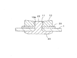
- FIG. 3 is an explanatory cross-sectional view of the button body attached to the cloth.
- FIG. 4 is a side view schematically showing a button mounting apparatus according to an embodiment of the present invention.
- FIG. 5 is a schematic front view of the button mounting device of FIG.
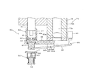
- FIG. 6 is an explanatory cross-sectional view schematically showing an enlarged main part of the button mounting device, and shows a state in which the intermediate material receiving part is in the first position.
- FIG. 1 is a perspective explanatory view showing a state in which a button body, an intermediate material, a cloth, and a button fixture are arranged concentrically up and down.
- FIG. 2 is a cross-sectional explanatory view of FIG.
- FIG. 3 is an
- FIG. 7 is an explanatory cross-sectional view showing a state in which the intermediate material receiving portion has moved from the state of FIG. 6 to the second position.
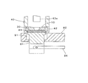
- FIG. 8 is an enlarged cross-sectional explanatory view showing the button attachment portion of FIG. 7, and the intermediate material receiving portion is in the initial position in the second position.
- FIG. 9 is an explanatory cross-sectional view showing, in an enlarged manner, a state in which the intermediate material receiving portion has moved to the delivery position in the second position.
- FIG. 10 is an explanatory cross-sectional view showing a state in which the intermediate material support portion has returned from the second position to the first position.
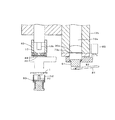
- FIG. 11 is an explanatory cross-sectional view showing a state in which the lowering of the first die at the button mounting portion and the lowering of the cutting blade at the intermediate material forming portion are simultaneously performed.
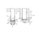
- FIG. 12 is an enlarged cross-sectional explanatory view showing a state where the button body is attached to the cloth by crimping the post of the button attachment.
- FIG. 13 is an enlarged cross-sectional explanatory view showing a state in which the intermediate material is cut out by the cutting blade and supplied onto the intermediate material receiving portion.
- FIG. 14 is an explanatory cross-sectional view showing a state in which the first die and the cutting blade have returned to the upper initial position after the state of FIG. 11.
- FIG. 12 is an enlarged cross-sectional explanatory view showing a state where the button body is attached to the cloth by crimping the post of the button attachment.
- FIG. 13 is an enlarged cross-sectional explanatory view showing a state in which the intermediate material is cut out by the cutting blade and supplied onto
- FIG. 15 is a cross-sectional explanatory view showing a state in which the button main body is attached to the cloth, showing an example in which the intermediate member is disposed between the button attachment tool and the cloth.
- FIG. 16 is a cross-sectional explanatory view showing another example of a set of a button body and a button fixture that can be attached by the button attachment device according to the present invention.
- FIG. 17 is a cross-sectional explanatory view showing still another example of a set of a button body and a button fixture that can be attached by the button attachment device according to the present invention.
- FIG. 18 is a cross-sectional explanatory view schematically showing a first die and a second die that hold the button body and the button fixture of FIG. 17, respectively.
- FIG. 19 is a cross-sectional explanatory view schematically showing another example of the first transport mechanism in the intermediate material transport section of the button mounting device.
- FIG. 20 is a cross-sectional explanatory view schematically illustrating an example of an intermediate material transport unit that does not need to lift the intermediate material at the second position.
- 21 is a cross-sectional view taken along line AA in FIG.
- FIG. 1 shows a button main body 10 that is attached to a cloth 1 such as clothes by a button attaching apparatus 100 (see FIG. 4 or the like) according to the present invention, a button attachment 20 that is used to attach the button main body 10 to the cloth 1,
- a button attaching apparatus 100 see FIG. 4 or the like
- FIG. 2 is a cross-sectional explanatory view of FIG. FIG.
- FIG. 3 is a cross-sectional explanatory view showing a state where the attachment of the button body 10 to the fabric 1 is completed.
- the button body 10 is used, for example, in pockets and decorations in jeans and the like.
- the button body 10 is a substantially disc-shaped metal or resin product, and vertically up and down (upper and lower are based on the paper surface of FIGS. 2 and 3). There is an opening 11 for attachment penetrating through.
- a post 22 (described later) of the button attachment 20 is passed through the cloth 1 and then swaged.
- the button body 10 has a top surface 12 with a gentle slope that decreases from the radially outer end to the inside opening 11 and a horizontal (refers to an arbitrary surface that is vertical or perpendicular to the button body axis). 13, an outer peripheral surface 14 that extends between the radially outer ends of the top surface 12 and the bottom surface 13, substantially parallel to the axis of the button body 11, and an opening 11 that extends between the radially inner ends of the top surface 12 and the bottom surface 13. And an inner peripheral surface 15 to be defined.
- the inner peripheral surface 15 is divided into an upper half portion 15a having a substantially constant diameter and a lower half portion 15b having a diameter reduced downward and slightly protruding inward in the radial direction.
- the button fixture 20 is a metal or resin product having a disk-shaped base 21 and a post 22 that protrudes concentrically with the base 21 from the center of the base 21 and has a sharp protruding end.
- the post 22 of the button fixture 20 penetrates the cloth 1 (and the intermediate material 30) upward when the button body 10 is attached to the cloth 1, and then passes through the opening 11 of the button body 10, and then a punch 43 described later. (See FIG. 6 etc.)
- the crimped post 22 (see FIG. 3) is locked by the lower half portion 15b of the inner peripheral surface 15 of the button body 10, thereby preventing the button body 10 from being pulled out from the opening 11.
- the intermediate material 30 is a circular resin sheet having flexibility.
- the intermediate material 30 is thinner than the fabric 1 and has a diameter slightly larger than the outer diameter of the button body 10. Therefore, the radially outer portion of the intermediate member 30 appears in a ring around the button body 10 attached to the fabric 1. Thereby, design nature can be improved by selecting the color, shape, etc. of intermediate material 30 suitably.
- the diameter of the intermediate member 30 may be equal to or less than the outer diameter of the button main body 10, and the shape of the button main body 10 is not limited to a circle but may be an ellipse, a polygon, a star, or the like. Further, the shape of the intermediate member 30 is not limited to a circle, and may be an ellipse, a polygon, a star, or the like. Further, the intermediate member 30 can play a role of supporting the reliable attachment of the button body 10 to the dough 1 by compensating for the dough thickness, particularly when the dough 1 is thin.
- FIG. 4 and 5 are a side view and a front view schematically showing the button mounting device 100 according to the embodiment of the present invention.
- FIG. 6 is an explanatory cross-sectional view schematically showing an enlarged main part of the button mounting device 100.
- the button attachment device 100 has a button attachment portion 60 including a first die 40 for holding the button main body 10 and a second die 50 for holding the button attachment 20 when the button main body 10 is attached to the cloth 1, and a long belt shape.
- the intermediate material forming portion 70 formed by cutting the intermediate material 30 from the sheet material 30a and the intermediate material 30 formed by the intermediate material forming portion 70 are held on the first die 40 holding the button body 10 or just before holding.
- an intermediate material conveying section 80 that conveys and holds the intermediate material.
- the first die 40 is disposed at the upper side, and the second die 50 is disposed at a concentric position with the lower first die 40.
- the first die 40 is disposed by the lifting unit (not shown) of the button attachment part 60 in a state where the cloth 1 is disposed between the first die 40 and the second die 50. 40 descends from the initial position of FIG. 6 (moves in a direction closer to the second die 50), and the second die 50 remains stationary. However, the second die 50 may move upward. In some cases, the second die 50 is disposed above and the first die 40 is disposed below, or the first and second dies 40 and 50 are disposed in the lateral direction.
- the first die 40 includes a cylindrical body 41, a button holding portion 42 incorporated near the lower end of the cylindrical body 41, a punch portion 43 that can move up and down inside the cylindrical body 41, and a cylinder under the button holding portion 42.
- An intermediate material holding portion 44 formed on the radially inner side of the lower end 41a of the body 41.
- the inner diameter of the cylindrical body 41 is slightly larger than the outer diameter of the button body 10.
- the button holding part 42 is opposed in one diametrical direction and has two holding members 42a capable of receiving the button main body 10 therebetween, and each of the button holding parts 42 slightly displaced outward from the initial position by receiving the button main body 10 therebetween. And a spring (not shown) that elastically biases the holding member 42a radially inward.
- Each holding member 42a has a protrusion 42b protruding slightly inward in the radial direction at the lower end thereof.
- the protrusion 42 b supports the bottom surface 13 of the button body 10.
- the upper surface of the protrusion 42b is inclined so as to be displaced outward in the radial direction against the bias of the spring when pressed downward from the button body 10.
- the lower surface of the protrusion 42b is flush with the bottom surface of the holding member 42a.
- Each holding member 42 a is a long arc-shaped member along the circumferential direction of the cylindrical body 41, and is disposed with respect to two circumferentially long through holes 42 c provided near the lower end of the cylindrical body 41.
- the cylindrical body 41 has a button introduction port (not shown) between the two through holes 42c, and the button body 10 supplied from an automatic supply device (not shown) is connected to the two holding members 42a from the button introduction port. It has come to accept in the meantime.
- the operator can manually hold the button body 10 from below with respect to the button holding portion 42. In this case, the button body 10 can be easily held by inclining the lower surface of the protrusion 42b of the holding member 42a.
- the lower end 41a below the through hole 42c of the cylindrical body 41 has a slightly larger inner diameter than the portion above the through hole 42c of the cylindrical body 41.
- the inner peripheral surface of the expanded lower end 41a and the lower surface of each holding member 42a define an intermediate material holding portion 44 that is concave upward.
- the diameter of the intermediate material holding portion 44 is set to be larger than the outer diameter of the button body 10 and slightly smaller than the diameter of the intermediate material 30. As a result, the intermediate material 30 having flexibility is fitted into the intermediate material holding portion 44 (see FIG. 9 and the like) and can be temporarily fixed and held.
- a button body in which an adhesive is applied in advance to the upper surface of the sheet material 30 a and held on the first die 40. 10 can be temporarily attached and held.
- the intermediate material 30 to which the adhesive is applied can be attached to the first die 40.
- the punch 43 can move up and down in the cylindrical body 41, and has a columnar punch base 43a having an outer diameter substantially equal to the inner diameter of the cylindrical body 41, and protrudes concentrically with the punch base 43a downward from the bottom surface of the punch base 43a. And a cylindrical punch body 43b having a smaller diameter than the punch base 43a.
- the outer shape is based on the diameter.
- the outer shape is the shape of the button. It becomes an outline.
- the intermediate material 30 is held by the intermediate material holding unit 44, but the outer shape thereof is preferably held over the entire region, but may be partially held. “Partial” means, for example, holding between two opposing points or holding at three points.
- the second die 50 surrounds the substantially cylindrical support 51 on which the button mounting member 20 is placed on the upper surface and the button mounting member 20 mounted on the support 51, and the cloth 1 is attached when the button body 10 is attached.
- the substantially cylindrical fabric support portion 52 for supporting the fabric support the coil spring 53 wound around the support body 51 for elastically supporting the fabric support portion 52, and the coil spring 53 fixed below the support body 51.
- a spring receiver 54 the support 51 has an upper end 51a with an increased outer diameter.
- the outer diameter of the upper end 51a is the same as or slightly larger than the outer diameter of the base 21 of the button mounting member 20.
- the dough support portion 52 includes a cylindrical support portion body 52a having an inner diameter substantially equal to the outer diameter of the upper end portion 51a of the support body 51, and a support that extends slightly downward after being stepped from the lower end of the support portion body 52a. And a base portion 52b.
- the support base 52 b is urged upward by the coil spring 53 and abuts against the lower surface of the upper end 51 a of the support 51 to be stationary.
- the upper end of the support portion main body 52 a is at the same height as the tip of the post 22 of the button mounting member 20 placed on the support 51.
- the button die 20 is supplied to the second die 50 on the support 51 from an automatic supply device (not shown). The operator may manually set the button attachment 20 on the support 51.
- the intermediate material forming unit 70 includes a sheet supply unit 71 in which a belt-shaped sheet material 30a is wound in a roll shape, and a pair of drive rollers 72 that feed the sheet material 30a from the sheet supply unit 71 by pulling the sheet material 30a. And a cutting unit 73 provided between the sheet supply unit 71 and the driving roller 72 for punching the intermediate material 30 in a circular shape from the sheet material 30a.
- the sheet material 30 a has a width that is slightly larger than the diameter of the intermediate material 30.
- the drive roller 72 is driven to rotate by a motor (not shown).
- the cutting portion 73 includes a cylindrical cutting blade 73a having a circular sharp edge at the lower end, and a cylindrical housing 73b that houses the cutting blade 73a and has a sheet passage 73c that allows the sheet material 30a to pass horizontally. .
- the cutting blade 72a can be moved up and down in the housing 73b by a cylinder or the like (not shown).
- the housing 73b has an inner diameter substantially equal to the outer diameter of the cutting blade 73a and is open downward.
- the sheet material 30a passes through the sheet path 73c from the front side to the back side (rear side) of FIG.
- the front-back direction in FIG. 6 is referred to as the “front-rear direction”.
- the seat passage 73c appears as a groove provided in the inner peripheral surface of the housing 73b in the cross section of FIG. 6 and the like, but penetrates the housing 73b in the front-rear direction.
- the housing 73b includes an upper housing main body 73ba and an annular portion 73bb whose upper surface is in contact with the bottom surface of the housing main body 73ba, and a recess that defines the sheet passage 73c is formed on the bottom surface of the housing main body 73ba.
- the sheet material 30a after the intermediate material 30 has been punched can be pulled by the drive roller 72 while remaining in a belt shape. Downstream of 72, the paper is taken up by a winding unit (not shown) or collected in a box, and then reused.
- the driving roller 72 may be a winding unit.
- the intermediate material conveying unit 80 includes a substantially cylindrical intermediate material receiving unit 81 that receives the intermediate material 30 separated from the sheet material 30a by the intermediate material forming unit 70 on the upper surface; A support member 82 that is long in the left-right direction and that is supported in the horizontal direction (perpendicular to the front-rear direction in the horizontal direction); an intermediate material receiving portion 81 is directly below the housing 73b of the intermediate material forming portion 70 The support member 82 is moved horizontally between the first position (see FIG. 6) coming to the second position (see FIG. 7) and the second position (see FIG. 7) where the intermediate material receiving portion 81 comes directly below the first die 40 of the button mounting portion 60.
- a horizontal cylinder 83 (see FIG.
- a left end portion is connected to a lower end portion of the intermediate material receiving portion 81, and a left-right intermediate portion is pivoted to an intermediate support portion 82e (see FIG. 7) integral with the support member 82.
- Movably linked when the support member 82 is in the second position, the left end of the operating rod 84 is lifted by lowering the right end of the operating rod 84 so that the intermediate member 30 on the intermediate member receiving portion 81 is moved.
- a vertical cylinder 85 for delivery to the intermediate material holding portion 44 of the first die 40.
- the intermediate material receiving portion 81 is concentric with the cutting blade 73a and the like at the first position, and concentric with the first die 40 at the second position.
- a support member 82 for horizontally moving the intermediate member 30 between the first and second positions, a horizontal cylinder 83, and the like constitute a first moving mechanism in the claims.
- the operating rod 84 for lifting the intermediate material 30 in the second position, the vertical cylinder 85, the intermediate material accommodating portion 91 described later of the support member 82, and the like constitute a second moving mechanism in the claims.
- the intermediate material receiving portion 81 has an upper end portion 81a whose outer diameter is slightly enlarged, and the intermediate material 30 is placed on the upper surface of the upper end portion 81a and conveyed.
- the outer diameter of the upper end portion 81 a is slightly smaller than the outer diameter of the intermediate material 30.
- a recess 81b that penetrates in the left-right direction and opens downward is formed at the lower end of the intermediate material receiving portion 81.
- the left end portion of the operating rod 84 is inserted into the concave portion 81b, and the shaft member 81c provided at the middle and the lower side of the concave portion 81b is passed through the left shaft hole 84a formed at the left end portion of the operating rod 84 to operate.
- the collar 84 is connected to the intermediate material receiving portion 81.
- the support member 82 has an opening 90 penetrating in the vertical direction for receiving and supporting the intermediate material receiving portion 81 at the left end portion.
- the opening 90 has an upper intermediate material accommodating portion 91 having a diameter slightly larger than the outer diameter of the intermediate material 30, and a diameter reduced in a step shape below the intermediate material accommodating portion 91, and an upper end portion of the intermediate material receiving portion 81. It is divided into a lower receiving portion supporting opening 92 having a diameter slightly larger than the outer diameter of a portion other than 81a (hereinafter referred to as “receiving portion main body 81d”).
- the intermediate material accommodating part 91 is prescribed
- the intermediate material accommodating portion 91 serves to reliably place the intermediate material 30 discharged from the housing 73b of the intermediate material forming portion 70 on the intermediate material receiving portion 81 when the intermediate material receiving portion 81 is in the first position. Fulfill. Further, when the intermediate material receiving portion 81 is in the second position, it serves as a guide when the upper end portion 81a of the intermediate material receiving portion 81 is moved upward as will be described later.
- the intermediate member receiving portion 81 is supported by the receiving portion main body 81 d protruding downward from the receiving portion supporting opening 92 and the upper end portion 81 a of the intermediate member receiving portion 81 being hooked on the bottom surface 91 b of the intermediate member receiving portion 91.
- An intermediate shaft member 82 f is provided in the intermediate support portion 82 e of the support member 82, and this intermediate shaft member 82 f is passed through an intermediate shaft hole 84 b formed in the intermediate portion in the left-right direction of the operating rod 84. Thereby, the operating rod 84 can be rotated around the intermediate shaft member 82f.
- the left end side of the operating rod 84 is inclined with respect to the horizontal so that it is lower than the right end side.
- the right end side is lowered and the left end side is raised. Almost horizontal.
- the first die 40 and the second die 50 are in the initial position, and the button body 10 and the button fixture 20 are supplied to the first die 40 and the second die 50 from the automatic supply device, respectively. Is held. In this state, the previous work of attaching the button main body 10 to the fabric 1 performed continuously is completed, and the first and second dies 40 and 50 are returned to the initial positions, and the button main body 10 for the next attachment is obtained.
- the button attachment 20 may be received.
- the cutting material 73 a is lowered with respect to the sheet material 30 a passing through the sheet passage 73 c to punch out the intermediate material 30, and this intermediate material 30 is formed on the support member 82 of the intermediate material conveying unit 80. It is mounted on the intermediate material receiving part 81 in the first position from the intermediate material accommodating part 91. The cutting blade 73a is raised and returned to the initial position.
- the intermediate material 30 is conveyed to the first die 40 as follows. First, by actuating the horizontal cylinder 83, as shown in FIG. 7, the support member 82 of the intermediate material conveying section 80 is moved horizontally to the left, and the intermediate material receiving section 81 is moved to the second position.
- FIG. 8 is an enlarged cross-sectional explanatory view showing the button mounting portion 60 of FIG.
- the vertical cylinder 85 When the vertical cylinder 85 is operated, the operating rod 84 rotates clockwise around the intermediate shaft member 82f, and the left end portion of the operating rod 84 rises from the initial position.
- the intermediate material receiving portion 81 is lifted through the intermediate material accommodating portion 91 of the support member 82 and is displaced to the upper and lower delivery position in the second position. In this delivery position, the intermediate material 30 on the intermediate material receiving portion 81 is fitted and held in the intermediate material holding portion 44 of the first die 40. Thereafter, the intermediate material receiving portion 81 is returned to the initial position of the second position, and is further returned to the first position as shown in FIG.
- the upper die 40 is lowered at the button attachment portion 60 to perform the attachment work of the button body 10 to the fabric 1, and at the same time, the cutting blade 73 a is lowered at the intermediate material forming portion 70.
- the next intermediate material 30 is cut out.
- the first die 40 holding the button main body 10 and the intermediate member 30 is lowered so that the post 22 of the button mounting tool 20 penetrates the fabric 1 and the intermediate member 30 and then the opening of the button main body 10. 11 protrudes above the button body 10.
- the protruding post 22 is crimped by the punch body 43b of the punch 43 of the first die 40 as shown in FIG.
- the button body 10 is fixed to the cloth 1 in a state where the intermediate material 30 is sandwiched between the button body 10 and the cloth 1.
- the punch main body 43 b pushes the button main body 10 downward during caulking, the holding of the button main body 10 by the holding member 42 a of the button holding portion 42 is released, and the intermediate material 30 is also discharged from the intermediate material holding portion 44. Is done.
- the cloth support portion 52 of the second die 50 is pushed downward by the cloth 1 during the attachment, and is displaced downward against the bias of the coil spring 53.
- FIG. 13 is an enlarged view showing a state in which the cutting blade 73 a is lowered in the intermediate material forming unit 70 and the intermediate material 30 is cut out from the sheet material 30 a and supplied onto the intermediate material receiving unit 81.
- the cutting blade 73 a protrudes downward from the lower end of the housing 73 b in the lowest state, and enters the intermediate material accommodating portion 91 of the support member 82.
- FIG. 14 shows the button attaching operation by the lowering of the first die 40 at the button attaching portion 60 and the formation of the intermediate member 30 by the lowering of the cutting blade 73a in the intermediate member forming portion 70 and the intermediate member receiving portion 81 shown in FIG.
- work to is shown.
- the button attachment portion 60 the place where the button body 10 is attached to the fabric 1 is shifted by an operator or a machine, and a new attachment location of the fabric 1 is disposed above the second die 50.
- first die 40 and the second die 50 do not release and hold the button body 10 and the button fixture 20 held before the attachment, but the button body 10 and the button attachment are almost simultaneously returned to the initial position.
- the tool 20 is automatically supplied to the first and second dies 40 and 50, respectively.
- the intermediate material forming part 70 the sheet material 30a moves and the next cutting location comes directly under the cutting blade 73a. Thereafter, the above-described operation is repeated, for example, the intermediate material receiving portion 81 moves from the first position to the second position and from the initial position of the second position to the delivery position.
- the intermediate material 30 is automatically formed by the intermediate material forming unit 70, and the intermediate material conveying unit 80 causes the button attachment portion to be formed.
- 60 can be automatically supplied and interposed between the button body 10 and the fabric 1 or between the button fixture 20 and the fabric 1. Therefore, the efficiency of the operation
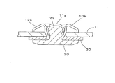
- FIG. 15 is a cross-sectional explanatory view showing a state in which the decorative button body 10 a is attached to the cloth 1 with the button attachment 20, and the intermediate member 30 is attached between the button attachment 20 and the cloth 1.
- the fabric 1, the button fixture 20, and the intermediate member 30 are substantially the same as those shown in FIG. 1 and the like, the same reference numerals are used in FIG.
- the button body 10a is formed by drawing a metal plate or the like, and defines a space for receiving and deforming the post 22 of the button fixture 20 penetrating the cloth 1 inside, and a hemispherical center protruding upward.
- the projection 11a includes a flange 12a that extends upward from the lower end of the central projection 11a and then extends radially outward. The lower end of the central convex portion 11a is slightly reduced radially inward to prevent the post 22 of the button attachment 20 after deformation from coming off.
- FIG. 16 is a cross-sectional explanatory view showing another example of a set of a button main body and a button attachment that can be attached by the button attachment device according to the present invention. Since the cloth 1 and the intermediate material 30 are substantially the same as those shown in FIG. 1 and the like, the same reference numerals are used in FIG.
- the button main body 10b shown in FIG. 16 is divided into a cylindrical body portion 10ba and a head portion 10bb whose outer diameter extends radially outward above the body portion 10ba.
- the head 10bb is put in and out of a button hole (not shown) such as clothes.
- the button body 10b includes a metal outer shell portion 11b and a resin core 11c.
- the outer shell portion 11b is formed on the bottom surface and peripheral side surface of the body portion 10ba and the lower surface and side portions of the head portion 10bb. It comprises an outer shell body portion 11ba that forms a shell, and an outer shell head portion 11bb that forms an outer shell on the upper surface and side portions of the head portion 10bb.
- the portion forming the side portion of the head portion 10bb in the outer shell head portion 11bb is overlapped and connected to the portion forming the side portion of the head portion 10bb in the outer shell body portion 11ba from the outside.
- the button fixture 20a has a base 21a and two pins 22a protruding from the base 21a.
- the base 21a includes a metal outer shell 21aa and a resin or metal core 21ab integrated with the pin 22a.
- An annular recess 11bc that is recessed upward is formed at the bottom of the outer shell body 11ba of the button fixture 20a so that the pin 22a can be easily penetrated.
- the intermediate material 30 is automatically supplied to the button main body 10b and the button attachment 20a as described above when being attached to the cloth 1, and interposed between the button main body 10b and the cloth 1 or between the button attachment 20a and the cloth 1. be able to.
- the button main body 10 (10a, 10b) and the button attachment 20 (20a) may be attached to the first die 40 and the second die 50 manually. In this case, in a state where the intermediate material 30 is held by the intermediate material conveyance unit 80, the process waits until the button body 10 and the button fixture 20 are attached to the first die 40 and the second die 50, and the attachment is completed.
- the operation of the intermediate material conveying unit 80 is performed by a switch.
- the operation of conveying the intermediate material 20 and holding it on the first die or the like, and the subsequent attachment of the button body 10 to the fabric 1 can be automatically performed.
- FIG. 17 is a cross-sectional explanatory view showing the button main body 10c and the button mounting tool 20b attached to the fabric 1 using the button mounting device 100, and the intermediate material 30 is interposed between the button main body 10c and the fabric 1. Has been placed. Since the fabric 1 and the intermediate material 30 are substantially the same as those shown in FIG. 1 and the like, the same reference numerals are used in FIG.
- the button body 10c is made of resin, and has a cylindrical body portion 10ca and a head portion 10cb whose outer diameter extends radially outward above the body portion 10ca.
- the head portion 10cb is a button hole (such as clothes). (Not shown).
- An inner hole 10cc extending upward from the bottom surface for receiving a post 22b, which will be described later, of the button attachment 20b is provided at the center of the trunk portion 10ca.
- the inner hole 10cc opens downward but does not penetrate upward.
- the button fixture 20b is also made of resin and has a disk-shaped base 21b and one post 22b protruding from the center of the base 21b.
- FIG. 18 is a cross-sectional explanatory view schematically showing the first die 40a and the second die 50 holding the button body 10c and the button fixture 20b, respectively.
- the first die 40a is substantially the same as the first die 40 described above except that it includes a columnar support member 40c in place of the punch 43, so that the cylindrical body 41, the button holding portion 42, and The same reference numbers are used for the intermediate material holding portions 44.
- the button main body 10 When the button main body 10 is attached to the fabric 1, the intermediate material 30 by the intermediate material conveyance unit 80 of the button attachment device 100 is held by the intermediate material holding portion 44 of the first die 40a, and then the first die 40a is lowered. As a result, the post 22b of the button fixture 20b penetrates through the fabric 1 and then the intermediate member 30, and then enters the inner hole 10cc of the button body 10c. At this time, the button body 10c is supported from above by the support member 40c, and the post 22b having a diameter slightly larger than the inner hole 10cc is deformed slightly from the annular groove 23b while being wedge-shaped with respect to the peripheral surface of the inner hole 10cc. Connect to In this way, the button body 10c and the intermediate member 30 are fixed to the fabric 1.
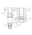
- FIG. 19 is a cross-sectional explanatory view schematically showing another example of the intermediate material conveying section 80 in the button mounting apparatus 100.
- the button mounting section 60 and the intermediate material forming section 70 are the same as those shown in FIG. Therefore, the same reference numerals are given and the description is omitted.
- the intermediate material transport unit 180 includes a disk-shaped intermediate material receiving unit 181 that receives the intermediate material 30 from the intermediate material forming unit 70 on its upper surface; a support member 182 that receives and supports the intermediate material receiving unit 181 in the opening 190; The intermediate material receiving portion 181 is supported between a first position where the intermediate material receiving portion 181 is located immediately below the housing 73b of the intermediate material forming portion 70 and a second position where the intermediate material receiving portion 181 is located immediately below the first die 40 of the button mounting portion 60.
- a motor 183 (see FIG.
- intermediate material 30 Is provided with a vertical cylinder 185 for delivering to the intermediate material holding portion 44 of the first die 40.
- the vertical cylinder 185 is disposed below the opening 190 of the support member 182.
- the support member 182 for horizontally moving the intermediate member 30 between the first and second positions, the motor 183, etc. constitute the first moving mechanism in the claims, and the intermediate member 30 is moved to the second position.
- the vertical cylinder 185 or the like for lifting constitutes the second moving mechanism in the claims.
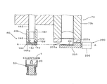
- FIG. 20 is a cross-sectional explanatory view schematically showing an example of the intermediate material transport unit 200 that does not need to lift the intermediate material 30 in the second position.
- 21 is a cross-sectional view taken along line AA in FIG.
- the intermediate material conveying unit 200 includes a rectangular intermediate material receiving member (intermediate material receiving unit) 201 that receives the intermediate material 30 from the intermediate material forming unit 70 on the upper surface 201a; and the intermediate material receiving member 201 is a housing of the intermediate material forming unit 70. Between the first position just below 73b and the second position where the intermediate material 30 on the intermediate material receiving member 201 is automatically delivered to the button holding portion 142 of the first die 40b described later of the button mounting portion 60. And a horizontal cylinder 202 for moving the intermediate member receiving member 201 horizontally.
- the upper surface 201a of the intermediate material receiving member 201 is provided with a stopper 201b that supports the right side portion of the periphery of the intermediate material 30 and prevents displacement of the intermediate material 30 on the upper surface 201a to the right side.
- the first die 40 b includes a cylindrical body 141, a button holding portion 142 provided at the lower end portion of the cylindrical body 141, a punch portion 143, and an intermediate material holding portion 144 provided under the cylindrical body 141.
- the button main body 10d shown in FIG. 20 is a male snap made of resin or metal, and has a disk-like base portion 11d, a cylindrical engagement protrusion 12d protruding from the base portion 11d, and a center of the base portion 11d.
- the button holding portion 142 of the first die 40b is configured to receive and elastically hold the engagement protrusion 12d of the button main body 10d at the lower end portion of the hollow shaft portion of the cylindrical body 141.
- the intermediate material holding portion 144 of the first die 40b is composed of a pair of front and rear holding plates 144a and 144a protruding downward from the lower end of the cylindrical body 141. The interval between the holding plates 144a and 144a is set slightly smaller than the diameter of the intermediate member 30.
- the intermediate material 30 is conveyed by the intermediate material receiving member 201 to the intermediate material holding portion 144 of the first die 40b at the second position, the intermediate material 30 is elastically sandwiched between the holding plates 144a and 144a. Held. At this time, the stopper 201b of the intermediate member receiving member 201 serves to push the intermediate member 30 between the left holding plates 144a and 144a. Next, an operation for attaching the button body 10d to the fabric 1 is performed.
Landscapes
- Engineering & Computer Science (AREA)
- Textile Engineering (AREA)
- Treatment Of Fiber Materials (AREA)
- Sewing Machines And Sewing (AREA)
- Perforating, Stamping-Out Or Severing By Means Other Than Cutting (AREA)
Description
10、10a、10b、10c、10d ボタン本体
20、20a、20b ボタン取付具
30 中間材
40、40a、40b 第1ダイ
42、142 ボタン保持部
43 パンチ
44、144 中間材保持部
50 第2ダイ
60 ボタン取付部
70 中間材形成部
71 シート供給部
72 駆動ローラ
73 切断部
73a 切断刃
80、180、200 中間材搬送部
81、181、201 中間材受け取り部
82、182 支持部材
83 水平シリンダ
84 作動杆
85、185 垂直シリンダ
90、190 開口部
91 中間材収容部
92 受け取り部支持開口
100 ボタン取付装置
Claims (8)
- ボタン本体(10、10a、10b、10c、10d)をボタン取付具(20、20a、20b)にて生地(1)に取り付けるためのボタン取付装置(100)であって、
ボタン本体(10、10a、10b、10c、10d)を保持させる第1ダイ(40、40a、40b)及びボタン取付具(20、20a、20b)を保持させる第2ダイ(50)を含むボタン取付部(60)と、
ボタン本体(10、10a、10b、10c、10d)と生地(1)との間又はボタン取付具(20、20a、20b)と生地(1)との間に介在させるための中間材(30)を、帯状のシート材(30a)から切断して形成する中間材形成部(70)と、
中間材形成部(70)で形成した中間材(30)をボタン取付部(60)に搬送して、第1ダイ(40、40a、40b)又は第2ダイ(50)に供給する中間材搬送部(80、180、200)とを備えたボタン取付装置。 - 前記中間材搬送部(80、180、200)は、ボタン取付部(60)に搬送した前記中間材(30)を、第1ダイ(40、40a、40b)又は第2ダイ(50)に保持させることを含む請求項1記載のボタン取付装置。
- 前記中間材搬送部(80、180、200)は、中間材形成部(70)で形成した中間材(30)を受け取る中間材受け取り部(81、181、201)と、中間材受け取り部(81、181、201)を、中間材形成部(70)に対応する第1位置と、ボタン取付部(60)に対応する第2位置との間に移動させるための第1移動機構(82、83;182、183;201、202)とを含む請求項1又は2記載のボタン取付装置。
- 前記中間材搬送部(80、180)は、前記第2位置において、前記中間材受け取り部(81、181)を、第1ダイ(40、40a)又は第2ダイ(50)から比較的離れた初期位置と、第1ダイ(40、40a)又は第2ダイ(50)に中間材(30)を受け渡すために第1ダイ(40、40a)又は第2ダイ(50)に近接した受け渡し位置との間に移動させるための第2移動機構(84、85、91;185)を含む請求項3記載のボタン取付装置。
- 前記中間材形成部(70)は、前記シート材(30a)がロール状に巻かれたシート供給部(71)と、シート材(30a)を引っ張ることにより、シート供給部(71)からシート材(30a)を送り出させる駆動ローラ(72)と、シート供給部(71)と駆動ローラ(72)との間に設けた、シート材(30a)から中間材(30)を切り離すための切断部(73)とを含む請求項1~4のいずれか1項記載のボタン取付装置。
- 前記第1ダイ(40、40a、40b)は、ボタン本体(10、10a、10b、10c、10d)の外形より大きい外形の、中間材(30)を保持可能な中間材保持部(44、144)を有する請求項1~5のいずれか1項記載のボタン取付装置。
- ボタン本体(10、10a、10b、10c、10d)を第1ダイ(40、40a、40b)に保持させると共に、ボタン取付具(20、20a、20b)を第2ダイ(50)に保持させる工程Aと、
帯状のシート材(30a)から中間材(30)を切断して形成する工程Bと、
前記中間材(30)を第1ダイ(40、40a、40b)又は第2ダイ(50)に自動的に搬送して受け渡す工程Cと、
ボタン本体(10、10a、10b、10c、10d)と生地(1)との間又はボタン取付具(20、20a、20b)と生地(1)との間に中間材(30)を介在させて、ボタン本体(10、10a、10b、10c、10d)を、ボタン取付具(20、20a、20b)にて生地(1)に取り付ける工程Dとを含むボタン取付方法。 - 前記工程Bと前記工程Dが同時に行われる請求項7記載のボタン取付方法。
Priority Applications (6)
| Application Number | Priority Date | Filing Date | Title |
|---|---|---|---|
| PCT/JP2012/050195 WO2013103017A1 (ja) | 2012-01-06 | 2012-01-06 | ボタン取付装置及びボタン取付方法 |
| US14/370,226 US9661887B2 (en) | 2012-01-06 | 2012-01-06 | Button mounting apparatus and button mounting method |
| CN201280052387.4A CN103917123B (zh) | 2012-01-06 | 2012-01-06 | 纽扣安装装置及纽扣安装方法 |
| MX2014008257A MX354010B (es) | 2012-01-06 | 2012-01-06 | Dispositivo de montaje de boton y metodo de montaje del boton. |
| JP2013552379A JP5816302B2 (ja) | 2012-01-06 | 2012-01-06 | ボタン取付装置及びボタン取付方法 |
| BR112014016760-5A BR112014016760B1 (pt) | 2012-01-06 | 2012-01-06 | aparelho para montagem de botões e método para montagem de botões |
Applications Claiming Priority (1)
| Application Number | Priority Date | Filing Date | Title |
|---|---|---|---|
| PCT/JP2012/050195 WO2013103017A1 (ja) | 2012-01-06 | 2012-01-06 | ボタン取付装置及びボタン取付方法 |
Publications (1)
| Publication Number | Publication Date |
|---|---|
| WO2013103017A1 true WO2013103017A1 (ja) | 2013-07-11 |
Family
ID=48745087
Family Applications (1)
| Application Number | Title | Priority Date | Filing Date |
|---|---|---|---|
| PCT/JP2012/050195 Ceased WO2013103017A1 (ja) | 2012-01-06 | 2012-01-06 | ボタン取付装置及びボタン取付方法 |
Country Status (6)
| Country | Link |
|---|---|
| US (1) | US9661887B2 (ja) |
| JP (1) | JP5816302B2 (ja) |
| CN (1) | CN103917123B (ja) |
| BR (1) | BR112014016760B1 (ja) |
| MX (1) | MX354010B (ja) |
| WO (1) | WO2013103017A1 (ja) |
Cited By (3)
| Publication number | Priority date | Publication date | Assignee | Title |
|---|---|---|---|---|
| CN105795567A (zh) * | 2016-05-05 | 2016-07-27 | 东莞市国昕缝纫设备有限公司 | 一种钉扣机 |
| CN112826165A (zh) * | 2021-03-02 | 2021-05-25 | 杭州天越服饰有限公司 | 一种气眼安装固定装置 |
| WO2022195876A1 (ja) * | 2021-03-19 | 2022-09-22 | Ykk株式会社 | ボタン取付装置 |
Families Citing this family (6)
| Publication number | Priority date | Publication date | Assignee | Title |
|---|---|---|---|---|
| CN102791155B (zh) * | 2009-12-25 | 2015-05-27 | Ykk株式会社 | 钮扣安装用上模 |
| KR101981869B1 (ko) * | 2014-12-01 | 2019-05-23 | 와이케이케이 가부시끼가이샤 | 암형 스냅 버튼의 상부 구조체, 암형 스냅 버튼 및 천에 대한 암형 스냅 버튼의 설치 방법 |
| EP3869988B1 (en) * | 2018-10-26 | 2022-11-30 | Paolini, Massimo | System for applying accessories on a support |
| CN110640030A (zh) * | 2019-11-13 | 2020-01-03 | 广东大舜科技有限公司 | 一种新型纽扣铆接机 |
| KR20230000531A (ko) | 2021-06-24 | 2023-01-03 | 삼성디스플레이 주식회사 | 표시 장치 |
| USD1062525S1 (en) * | 2021-12-24 | 2025-02-18 | Ykk Corporation | Snap button |
Citations (4)
| Publication number | Priority date | Publication date | Assignee | Title |
|---|---|---|---|---|
| JPS52129508U (ja) * | 1976-03-29 | 1977-10-01 | ||
| JPH09209209A (ja) * | 1996-01-26 | 1997-08-12 | Kiyoshi Takeda | スナップファスナー取付け機とリベット体支持装置 |
| JP2003019375A (ja) * | 2001-07-10 | 2003-01-21 | Juki Corp | ボタン付け用ミシン |
| JP2009183444A (ja) * | 2008-02-06 | 2009-08-20 | Morito Co Ltd | パッキン付止め具 |
Family Cites Families (6)
| Publication number | Priority date | Publication date | Assignee | Title |
|---|---|---|---|---|
| DE3519878A1 (de) * | 1985-06-03 | 1986-12-04 | Schaeffer Scovill Verbindungstechnik GmbH, 5600 Wuppertal | Maschine zum ansetzen von knoepfen, nieten oder dergleichen an kleidungsstuecke |
| DE3822519A1 (de) * | 1988-07-04 | 1990-01-11 | Prym Werke William | Vorrichtung zum winkelgerechten positionieren eines hart-kurzwaren-artikels, wie eines knopfes od. dgl., im werkzeug einer ansetzmaschine |
| DE4117767A1 (de) * | 1991-05-31 | 1992-12-03 | Schaeffer Gmbh | Maschine zum ansetzen von knoepfen, nieten oder dergleichen, vorzugsweise an bekleidungsstuecken |
| JP2575299B2 (ja) * | 1995-01-20 | 1997-01-22 | 株式会社久永製作所 | ホックにおけるキャップとバネのカシメ方法 |
| JP4323224B2 (ja) * | 2003-06-06 | 2009-09-02 | Ykk株式会社 | ボタン取付装置 |
| JP4221344B2 (ja) * | 2004-09-03 | 2009-02-12 | Ykk株式会社 | 止め具およびボタン |
-
2012
- 2012-01-06 CN CN201280052387.4A patent/CN103917123B/zh active Active
- 2012-01-06 WO PCT/JP2012/050195 patent/WO2013103017A1/ja not_active Ceased
- 2012-01-06 JP JP2013552379A patent/JP5816302B2/ja active Active
- 2012-01-06 BR BR112014016760-5A patent/BR112014016760B1/pt active IP Right Grant
- 2012-01-06 MX MX2014008257A patent/MX354010B/es active IP Right Grant
- 2012-01-06 US US14/370,226 patent/US9661887B2/en active Active
Patent Citations (4)
| Publication number | Priority date | Publication date | Assignee | Title |
|---|---|---|---|---|
| JPS52129508U (ja) * | 1976-03-29 | 1977-10-01 | ||
| JPH09209209A (ja) * | 1996-01-26 | 1997-08-12 | Kiyoshi Takeda | スナップファスナー取付け機とリベット体支持装置 |
| JP2003019375A (ja) * | 2001-07-10 | 2003-01-21 | Juki Corp | ボタン付け用ミシン |
| JP2009183444A (ja) * | 2008-02-06 | 2009-08-20 | Morito Co Ltd | パッキン付止め具 |
Cited By (5)
| Publication number | Priority date | Publication date | Assignee | Title |
|---|---|---|---|---|
| CN105795567A (zh) * | 2016-05-05 | 2016-07-27 | 东莞市国昕缝纫设备有限公司 | 一种钉扣机 |
| CN112826165A (zh) * | 2021-03-02 | 2021-05-25 | 杭州天越服饰有限公司 | 一种气眼安装固定装置 |
| CN112826165B (zh) * | 2021-03-02 | 2022-07-29 | 山东省科创服饰有限公司 | 一种气眼安装固定装置 |
| WO2022195876A1 (ja) * | 2021-03-19 | 2022-09-22 | Ykk株式会社 | ボタン取付装置 |
| CN116981374A (zh) * | 2021-03-19 | 2023-10-31 | Ykk株式会社 | 纽扣安装装置 |
Also Published As
| Publication number | Publication date |
|---|---|
| MX2014008257A (es) | 2014-09-25 |
| CN103917123B (zh) | 2016-08-31 |
| MX354010B (es) | 2018-02-08 |
| BR112014016760B1 (pt) | 2021-01-26 |
| BR112014016760A8 (pt) | 2017-07-04 |
| US9661887B2 (en) | 2017-05-30 |
| BR112014016760A2 (pt) | 2017-06-13 |
| CN103917123A (zh) | 2014-07-09 |
| US20150052666A1 (en) | 2015-02-26 |
| JPWO2013103017A1 (ja) | 2015-05-11 |
| JP5816302B2 (ja) | 2015-11-18 |
Similar Documents
| Publication | Publication Date | Title |
|---|---|---|
| JP5816302B2 (ja) | ボタン取付装置及びボタン取付方法 | |
| EP3584019B1 (en) | Stripping device for press mold | |
| US12525857B2 (en) | Laminated iron core, manufacturing method of laminated iron core, and progressive die machine | |
| KR101134611B1 (ko) | 압입기를 구비한 스냅링 자동조립체결장치 | |
| CA1302360C (en) | Apparatus and method for applying a fastener to sheet material | |
| US7631679B1 (en) | Combination hole puncher with cartridge of reinforcers | |
| US6905451B2 (en) | Rope handle forming machine and method | |
| JP5603165B2 (ja) | 環状部材の製造装置及び製造方法 | |
| JP6239952B2 (ja) | ボタン取付装置及びボタン取付方法 | |
| JP6976294B2 (ja) | Oリングマガジン及びoリング供給装置 | |
| JP5563063B2 (ja) | ハトメ取付装置及びハトメ取付方法 | |
| US6766677B1 (en) | Die curl assembly | |
| WO2025017941A1 (ja) | 順送り金型装置及び鉄心薄板の製造方法 | |
| CN215225168U (zh) | 鞋扣自动装扣机 | |
| JP6002988B2 (ja) | ラベラー | |
| KR20140131075A (ko) | 팸너트 공급장치 | |
| EP2404517A1 (en) | Fixing device of ornament and method for fixing ornament by fixing device | |
| US1240207A (en) | Punching and setting machine. | |
| WO2014097483A1 (ja) | ボタン類取付装置及びボタン類取付方法 | |
| WO2022195876A1 (ja) | ボタン取付装置 | |
| US1188423A (en) | Manufacture of eyelets or the like. | |
| JP2002192251A (ja) | 深絞り成形型 | |
| JP6528970B2 (ja) | ドアトリムの製造装置及びドアトリムの製造方法 | |
| US9656315B2 (en) | Producing composite fiber/metal workpieces | |
| JPS5860005A (ja) | 膜体のロ−プ孔補強金具取付装置 |
Legal Events
| Date | Code | Title | Description |
|---|---|---|---|
| 121 | Ep: the epo has been informed by wipo that ep was designated in this application |
Ref document number: 12864248 Country of ref document: EP Kind code of ref document: A1 |
|
| ENP | Entry into the national phase |
Ref document number: 2013552379 Country of ref document: JP Kind code of ref document: A |
|
| WWE | Wipo information: entry into national phase |
Ref document number: 2014/07839 Country of ref document: TR Ref document number: MX/A/2014/008257 Country of ref document: MX |
|
| NENP | Non-entry into the national phase |
Ref country code: DE |
|
| REG | Reference to national code |
Ref country code: BR Ref legal event code: B01A Ref document number: 112014016760 Country of ref document: BR |
|
| WWE | Wipo information: entry into national phase |
Ref document number: 14370226 Country of ref document: US |
|
| 122 | Ep: pct application non-entry in european phase |
Ref document number: 12864248 Country of ref document: EP Kind code of ref document: A1 |
|
| ENP | Entry into the national phase |
Ref document number: 112014016760 Country of ref document: BR Kind code of ref document: A2 Effective date: 20140707 |