WO2013099441A1 - 電気デバイス用負極活物質 - Google Patents
電気デバイス用負極活物質 Download PDFInfo
- Publication number
- WO2013099441A1 WO2013099441A1 PCT/JP2012/078602 JP2012078602W WO2013099441A1 WO 2013099441 A1 WO2013099441 A1 WO 2013099441A1 JP 2012078602 W JP2012078602 W JP 2012078602W WO 2013099441 A1 WO2013099441 A1 WO 2013099441A1
- Authority
- WO
- WIPO (PCT)
- Prior art keywords
- negative electrode
- active material
- electrode active
- alloy
- mass
- Prior art date
Links
Images


Classifications
-
- H—ELECTRICITY
- H01—ELECTRIC ELEMENTS
- H01M—PROCESSES OR MEANS, e.g. BATTERIES, FOR THE DIRECT CONVERSION OF CHEMICAL ENERGY INTO ELECTRICAL ENERGY
- H01M4/00—Electrodes
- H01M4/02—Electrodes composed of, or comprising, active material
- H01M4/36—Selection of substances as active materials, active masses, active liquids
- H01M4/38—Selection of substances as active materials, active masses, active liquids of elements or alloys
- H01M4/386—Silicon or alloys based on silicon
-
- C—CHEMISTRY; METALLURGY
- C22—METALLURGY; FERROUS OR NON-FERROUS ALLOYS; TREATMENT OF ALLOYS OR NON-FERROUS METALS
- C22C—ALLOYS
- C22C13/00—Alloys based on tin
-
- C—CHEMISTRY; METALLURGY
- C22—METALLURGY; FERROUS OR NON-FERROUS ALLOYS; TREATMENT OF ALLOYS OR NON-FERROUS METALS
- C22C—ALLOYS
- C22C30/00—Alloys containing less than 50% by weight of each constituent
- C22C30/04—Alloys containing less than 50% by weight of each constituent containing tin or lead
-
- C—CHEMISTRY; METALLURGY
- C23—COATING METALLIC MATERIAL; COATING MATERIAL WITH METALLIC MATERIAL; CHEMICAL SURFACE TREATMENT; DIFFUSION TREATMENT OF METALLIC MATERIAL; COATING BY VACUUM EVAPORATION, BY SPUTTERING, BY ION IMPLANTATION OR BY CHEMICAL VAPOUR DEPOSITION, IN GENERAL; INHIBITING CORROSION OF METALLIC MATERIAL OR INCRUSTATION IN GENERAL
- C23C—COATING METALLIC MATERIAL; COATING MATERIAL WITH METALLIC MATERIAL; SURFACE TREATMENT OF METALLIC MATERIAL BY DIFFUSION INTO THE SURFACE, BY CHEMICAL CONVERSION OR SUBSTITUTION; COATING BY VACUUM EVAPORATION, BY SPUTTERING, BY ION IMPLANTATION OR BY CHEMICAL VAPOUR DEPOSITION, IN GENERAL
- C23C14/00—Coating by vacuum evaporation, by sputtering or by ion implantation of the coating forming material
- C23C14/06—Coating by vacuum evaporation, by sputtering or by ion implantation of the coating forming material characterised by the coating material
- C23C14/14—Metallic material, boron or silicon
- C23C14/16—Metallic material, boron or silicon on metallic substrates or on substrates of boron or silicon
- C23C14/165—Metallic material, boron or silicon on metallic substrates or on substrates of boron or silicon by cathodic sputtering
-
- C—CHEMISTRY; METALLURGY
- C23—COATING METALLIC MATERIAL; COATING MATERIAL WITH METALLIC MATERIAL; CHEMICAL SURFACE TREATMENT; DIFFUSION TREATMENT OF METALLIC MATERIAL; COATING BY VACUUM EVAPORATION, BY SPUTTERING, BY ION IMPLANTATION OR BY CHEMICAL VAPOUR DEPOSITION, IN GENERAL; INHIBITING CORROSION OF METALLIC MATERIAL OR INCRUSTATION IN GENERAL
- C23C—COATING METALLIC MATERIAL; COATING MATERIAL WITH METALLIC MATERIAL; SURFACE TREATMENT OF METALLIC MATERIAL BY DIFFUSION INTO THE SURFACE, BY CHEMICAL CONVERSION OR SUBSTITUTION; COATING BY VACUUM EVAPORATION, BY SPUTTERING, BY ION IMPLANTATION OR BY CHEMICAL VAPOUR DEPOSITION, IN GENERAL
- C23C14/00—Coating by vacuum evaporation, by sputtering or by ion implantation of the coating forming material
- C23C14/22—Coating by vacuum evaporation, by sputtering or by ion implantation of the coating forming material characterised by the process of coating
- C23C14/34—Sputtering
- C23C14/35—Sputtering by application of a magnetic field, e.g. magnetron sputtering
-
- H—ELECTRICITY
- H01—ELECTRIC ELEMENTS
- H01M—PROCESSES OR MEANS, e.g. BATTERIES, FOR THE DIRECT CONVERSION OF CHEMICAL ENERGY INTO ELECTRICAL ENERGY
- H01M4/00—Electrodes
- H01M4/02—Electrodes composed of, or comprising, active material
- H01M4/13—Electrodes for accumulators with non-aqueous electrolyte, e.g. for lithium-accumulators; Processes of manufacture thereof
- H01M4/133—Electrodes based on carbonaceous material, e.g. graphite-intercalation compounds or CFx
-
- H—ELECTRICITY
- H01—ELECTRIC ELEMENTS
- H01M—PROCESSES OR MEANS, e.g. BATTERIES, FOR THE DIRECT CONVERSION OF CHEMICAL ENERGY INTO ELECTRICAL ENERGY
- H01M4/00—Electrodes
- H01M4/02—Electrodes composed of, or comprising, active material
- H01M4/13—Electrodes for accumulators with non-aqueous electrolyte, e.g. for lithium-accumulators; Processes of manufacture thereof
- H01M4/134—Electrodes based on metals, Si or alloys
-
- H—ELECTRICITY
- H01—ELECTRIC ELEMENTS
- H01M—PROCESSES OR MEANS, e.g. BATTERIES, FOR THE DIRECT CONVERSION OF CHEMICAL ENERGY INTO ELECTRICAL ENERGY
- H01M4/00—Electrodes
- H01M4/02—Electrodes composed of, or comprising, active material
- H01M4/36—Selection of substances as active materials, active masses, active liquids
- H01M4/38—Selection of substances as active materials, active masses, active liquids of elements or alloys
- H01M4/387—Tin or alloys based on tin
-
- H—ELECTRICITY
- H01—ELECTRIC ELEMENTS
- H01M—PROCESSES OR MEANS, e.g. BATTERIES, FOR THE DIRECT CONVERSION OF CHEMICAL ENERGY INTO ELECTRICAL ENERGY
- H01M2220/00—Batteries for particular applications
- H01M2220/20—Batteries in motive systems, e.g. vehicle, ship, plane
-
- H—ELECTRICITY
- H01—ELECTRIC ELEMENTS
- H01M—PROCESSES OR MEANS, e.g. BATTERIES, FOR THE DIRECT CONVERSION OF CHEMICAL ENERGY INTO ELECTRICAL ENERGY
- H01M4/00—Electrodes
- H01M4/02—Electrodes composed of, or comprising, active material
- H01M4/04—Processes of manufacture in general
- H01M4/0402—Methods of deposition of the material
- H01M4/0421—Methods of deposition of the material involving vapour deposition
- H01M4/0423—Physical vapour deposition
- H01M4/0426—Sputtering
-
- Y—GENERAL TAGGING OF NEW TECHNOLOGICAL DEVELOPMENTS; GENERAL TAGGING OF CROSS-SECTIONAL TECHNOLOGIES SPANNING OVER SEVERAL SECTIONS OF THE IPC; TECHNICAL SUBJECTS COVERED BY FORMER USPC CROSS-REFERENCE ART COLLECTIONS [XRACs] AND DIGESTS
- Y02—TECHNOLOGIES OR APPLICATIONS FOR MITIGATION OR ADAPTATION AGAINST CLIMATE CHANGE
- Y02E—REDUCTION OF GREENHOUSE GAS [GHG] EMISSIONS, RELATED TO ENERGY GENERATION, TRANSMISSION OR DISTRIBUTION
- Y02E60/00—Enabling technologies; Technologies with a potential or indirect contribution to GHG emissions mitigation
- Y02E60/10—Energy storage using batteries
Definitions
- the present invention relates to a negative electrode active material for an electric device such as a secondary battery or a capacitor, which is suitably used as a power source for driving a motor such as an electric vehicle (EV) or a hybrid electric vehicle (HEV). Furthermore, the present invention relates to a negative electrode, an electric device and a lithium ion secondary battery using the negative electrode active material.
- a negative electrode active material for an electric device such as a secondary battery or a capacitor, which is suitably used as a power source for driving a motor such as an electric vehicle (EV) or a hybrid electric vehicle (HEV).
- EV electric vehicle
- HEV hybrid electric vehicle
- the present invention relates to a negative electrode, an electric device and a lithium ion secondary battery using the negative electrode active material.
- the secondary battery used for driving the vehicle motor is particularly required to have a high capacity and excellent cycle characteristics. For this reason, lithium ion secondary batteries having high theoretical energy are attracting attention among various secondary batteries.
- Patent Document 1 discloses an electrode material and an electrode structure capable of obtaining a high-capacity battery with low resistance and high charge / discharge efficiency, and a secondary battery using these. Proposals have been made. That is, in Patent Document 1, alloy particles in a solid state mainly composed of silicon, in which microcrystals or amorphous materials composed of elements other than silicon are dispersed in microcrystalline silicon or amorphized silicon. An electrode material comprising particles is disclosed.
- An object of the present invention is to provide a negative electrode active material for an electric device which can suppress cycle transition of amorphous-crystal and improve cycle life and has a high capacity.
- a further object of the present invention is to provide a negative electrode, an electrical device, and a lithium ion secondary battery to which such a negative electrode active material is applied.
- the negative electrode active material for an electric device has a mass ratio of 35% ⁇ Si ⁇ 78%, 7% ⁇ Sn ⁇ 30%, 0% ⁇ Ti ⁇ 37%, and / or 35% ⁇ It has an alloy containing components in the region of Si ⁇ 52%, 30% ⁇ Sn ⁇ 51%, 0% ⁇ Ti ⁇ 35%, and the balance being inevitable impurities.
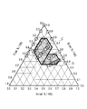
- FIG. 1 is a ternary composition diagram plotting the alloy components formed in the examples together with the composition range of the Si—Sn—Ti alloy constituting the negative electrode active material for an electric device according to the embodiment of the present invention. is there.
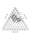
- FIG. 2 is a ternary composition diagram showing a preferred composition range of the Si—Sn—Ti alloy constituting the negative electrode active material of the present embodiment.
- FIG. 3 is a ternary composition diagram showing a more preferable composition range of the Si—Sn—Ti alloy constituting the negative electrode active material of the present embodiment.
- FIG. 4 is a ternary composition diagram showing a more preferable composition range of the Si—Sn—Ti alloy constituting the negative electrode active material of the present embodiment.
- FIG. 1 is a ternary composition diagram plotting the alloy components formed in the examples together with the composition range of the Si—Sn—Ti alloy constituting the negative electrode active material for an electric device according to the embodiment of the present invention. is there.
- FIG. 2 is a
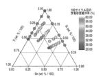
- FIG. 5 is a diagram showing the relationship between the initial discharge capacity of the batteries obtained in Examples and Comparative Examples and the alloy composition of the negative electrode active material.
- FIG. 6 is a graph showing the relationship between the discharge capacity retention ratio at the 50th cycle and the alloy composition of the negative electrode active material in the batteries obtained in the examples and comparative examples.
- FIG. 7 is a graph showing the relationship between the discharge capacity retention rate at the 100th cycle and the alloy composition of the negative electrode active material in the batteries obtained in the examples and comparative examples.
- FIG. 8 is a schematic cross-sectional view showing an example of a lithium ion secondary battery according to an embodiment of the present invention.
- the negative electrode active material for an electric device of the present embodiment the negative electrode for an electric device using the same, and the electric device will be described in detail.
- a negative electrode active material for an electric device, a negative electrode for an electric device, and an electric device will be described by taking a lithium ion secondary battery as an example of an electric device to which the negative electrode active material can be applied as an example.
- the dimensional ratios in the drawings are exaggerated for convenience of explanation, and may differ from actual ratios.
- the negative electrode active material for an electrical device of this embodiment contains an alloy containing any component in the first region indicated by symbol A and the second region indicated by symbol B in FIG. Have. And the said 1st area
- region is 35 mass% or more of silicon (Si) of 78 mass% or less, tin (Sn) of 7 mass% or more and 30 mass% or less, and titanium (Ti) of more than 0 and 37 mass% or less. It is an area to include.
- the second region is a region containing 35% by mass or more and 52% by mass or less of Si, 30% by mass or more and 51% by mass or less of Sn, and more than 0 and 35% by mass or less of Ti.
- “wt% / 100” in FIGS. 1 to 4 indicates that the mass% of each component is divided by 100.
- tin (Sn) is selected as the first additive element and titanium (Ti) is selected as the second additive element with respect to silicon (Si).
- the alloy absorbs lithium ions when the battery is charged and releases lithium ions when discharged.
- tin (Sn) as a first additive element that suppresses the amorphous-crystal phase transition and improves the cycle life
- a second additive element as the second additive element Contains titanium (Ti).
- the negative electrode active material of the Si (Si—Sn—Ti-based) alloy according to the present embodiment can exhibit high capacity and high cycle durability, and can also exhibit high charge / discharge efficiency in the initial stage. it can.
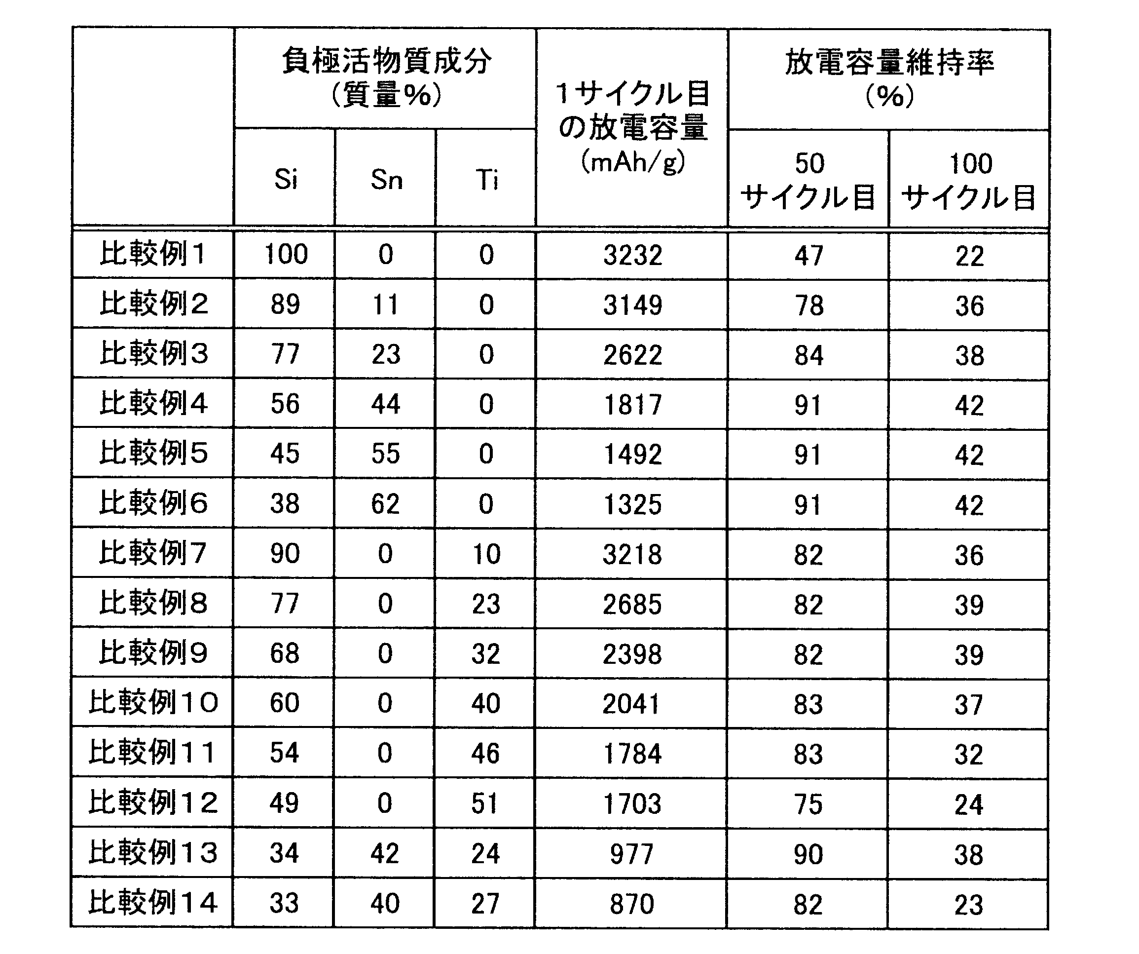
- the negative electrode active material of the present embodiment is characterized by comprising a Si—Sn—Ti alloy having the above composition range. And when content of each component of silicon, tin, and titanium deviates from the said range, initial discharge capacity exceeding 1000 mAh / g is not obtained, and also as shown in the below-mentioned Example, discharge capacity after 50 cycles The maintenance rate cannot exceed 90%.
- the titanium content is in the range of 7% by mass or more. That is, as indicated by the symbol C in FIG. 2, the first region includes 35 mass% or more and 78 mass% or less of silicon (Si), 7 mass% or more and 30 mass% or less of tin (Sn), or 7 mass% or more. A region containing 37 mass% or less of titanium (Ti) is preferable. 2, the second region includes 35 mass% or more and 52 mass% or less of Si, 30 mass% or more and 51 mass% or less of Sn, 7 mass% or more and 35 mass% or less of Ti. It is preferable that it is the area
- the first region includes 35 mass% to 68 mass% Si, 7 mass% to 30 mass% Sn. , And preferably a region containing 8 mass% or more and 37 mass% or less of Ti.
- the second region includes 39% by mass to 52% by mass of Si, 30% by mass to 51% by mass of Sn, and 7% by mass to 20% by mass of Ti. It is desirable that the region includes
- the negative electrode active material of the present embodiment includes an alloy containing the components in the region indicated by symbol G in FIG. 4 and the balance being inevitable impurities.
- symbol G is an area
- the negative electrode active material of this embodiment cannot contain impurities derived from raw materials and manufacturing methods in addition to the above three components.
- the content of such inevitable impurities is preferably less than 0.5% by mass, and more preferably less than 0.1% by mass.
- the alloy included in the negative electrode active material of the present embodiment has a mass ratio of 35% ⁇ Si ⁇ 78%, 7% ⁇ Sn ⁇ 30%, 0% ⁇ Ti ⁇ 37%, And / or 35% ⁇ Si ⁇ 52%, 30% ⁇ Sn ⁇ 51%, 0% ⁇ Ti ⁇ 35%, and the remainder is inevitable impurities.
- the alloy has a mass ratio of 35% ⁇ Si ⁇ 78%, 7% ⁇ Sn ⁇ 30%, 0% ⁇ Ti ⁇ 37%, and / or 35% ⁇ Si ⁇ 52%, It consists only of components in the region of 30% ⁇ Sn ⁇ 51%, 0% ⁇ Ti ⁇ 35%, and inevitable impurities.
- the method for producing the negative electrode active material of the present embodiment that is, the Si—Sn—Ti alloy having the above composition is not particularly limited, and can be produced using various conventionally known production methods. In short, since there is almost no difference in alloy state and characteristics depending on the production method, any conventionally known production method can be applied without any problem.
- an alloy in a thin film state can be given, for example.
- a method for producing such an alloy for example, a multi-source physical vapor deposition method (multi-source PVD method) such as a sputtering method, a resistance heating method, or a laser ablation method, or a multi-source chemical vapor deposition method such as a chemical vapor deposition method ( Multi-source CVD method).
- multi-source PVD method multi-source physical vapor deposition method
- a sputtering method such as a sputtering method, a resistance heating method, or a laser ablation method
- a multi-source chemical vapor deposition method such as a chemical vapor deposition method ( Multi-source CVD method).
- the negative electrode active material such as a binder and a conductive additive
- an alloy thin film as the negative electrode active material can be used as a negative electrode as it is. Therefore, it is excellent in the viewpoint that the high capacity
- an independently controlled ternary DC magnetron sputtering apparatus can be used as a multi-element DC magnetron sputtering apparatus.
- Si—Sn—Ti alloy thin films having various alloy compositions and thicknesses can be freely formed on the surface of the substrate (current collector).
- various targets can be obtained by changing the power of the DC power source by fixing the sputtering time by setting the target 1 to silicon (Si), the target 2 to tin (Sn), and the target 3 to titanium (Ti). Can be obtained.
- ternary alloy samples having various compositions can be obtained.
- the power of the DC power source to 185 W for Si, 0 to 120 W for Sn, and 0 to 150 W for Ti.
- the negative electrode active material layer of this embodiment can use the thin film of the Si—Sn—Ti alloy.
- the negative electrode active material layer can also be a layer containing particles of the Si—Sn—Ti alloy. That is, as another example of the negative electrode active material of the present embodiment, for example, an alloy in the form of particles can be cited.
- a mechanical alloy method can be used as a method for producing an alloy in the form of particles having such a composition.
- a method of solidifying by a rapid cooling roll method after arc plasma melting can be used.
- a slurry is prepared by adding a binder, a conductive additive, a viscosity adjusting solvent, etc. to the alloy particles, and applying this slurry to a current collector.
- a negative electrode can be formed. This manufacturing method is superior in terms of easy mass production as compared to the above-described manufacturing method of the alloy thin film and easy practical application as an actual battery electrode.
- the average particle diameter (D50) of the alloy is preferably in the range of 1 to 20 ⁇ m. However, it may be out of this range as long as the above-described effects can be expressed effectively.
- the negative electrode for an electric device includes a negative electrode active material containing the Si—Sn—Ti alloy.
- a typical lithium ion secondary battery as such an electric device includes a negative electrode in which a negative electrode active material layer containing the negative electrode active material is provided on a current collector surface.
- a positive electrode obtained by applying a positive electrode active material or the like to a positive electrode current collector and a negative electrode obtained by applying a negative electrode active material or the like to a negative electrode current collector are connected via an electrolyte layer. And it has the structure where the laminated body formed from a positive electrode, an electrolyte layer, and a negative electrode was accommodated in the battery case.
- the positive electrode In the lithium ion secondary battery, the positive electrode has a structure in which a positive electrode active material layer is formed on one side or both sides of a current collector (positive electrode current collector). And as a collector, electroconductive materials, such as aluminum foil, copper foil, nickel foil, and stainless steel foil, can be used. Moreover, a positive electrode active material layer contains a conductive support agent and a binder as needed with a positive electrode active material.
- the thickness of the current collector is not particularly limited, but generally it is preferably about 1 to 30 ⁇ m. Moreover, the compounding ratio of these positive electrode active materials, a conductive support agent, and a binder in a positive electrode active material layer is not specifically limited.
- the positive electrode active material one or more of positive electrode materials capable of occluding and releasing lithium are included, and a binder and a conductive aid may be included as necessary.
- a lithium-containing compound As the positive electrode material capable of inserting and extracting lithium, for example, a lithium-containing compound is preferable from the viewpoint of capacity and output characteristics.
- lithium-containing compounds include composite oxides containing lithium and transition metal elements, phosphate compounds containing lithium and transition metal elements, sulfate compounds containing lithium and transition metal elements, solid solution systems, 3 Examples thereof include an original system, a NiMn system, a NiCo system, and a spinel manganese system.
- the composite oxide containing lithium and a transition metal element include LiMn 2 O 4 , LiCoO 2 , LiNiO 2 , Li (NiMnCo) O 2 , Li (LiNiMnCo) O 2 , LiFePO 4, and these transition metals. Examples thereof include those partially substituted with other elements.
- the phosphate compound containing lithium and a transition metal element include LiFePO 4 and LiFeMnPO 4 .
- these phosphoric acid compounds those in which a part of the transition metal is substituted with another element may be used for the purpose of stabilizing the structure.
- Specific examples of the sulfuric acid compound containing lithium and a transition metal element include Li x Fe 2 (SO 4 ) 3 and the like.
- the solid solution system includes xLiMO 2 ⁇ (1-x) Li 2 NO 3 (0 ⁇ x ⁇ 1, M is one or more transition metals having an average oxidation state of 3+, and N is an average oxidation state of 4+), LiRO 2- LiMn 2 O 4 (R is a transition metal element such as Ni, Mn, Co, Fe, etc.).
- Examples of the ternary system include nickel / cobalt / manganese composite cathode materials.
- Examples of the spinel manganese system include LiMn 2 O 4 .
- As the NiMn system include LiNi 0.5 Mn 1.5 O 4 and the like.
- Examples of the NiCo system include Li (NiCo) O 2 .
- two or more positive electrode active materials may be used in combination.
- a lithium-transition metal composite oxide is used as the positive electrode active material from the viewpoint of capacity and output characteristics.
- the particle size of the positive electrode active material is not particularly limited. However, in general, the finer is desirable, and the average particle diameter of the positive electrode active material may be about 1 to 30 ⁇ m, and more preferably about 5 to 20 ⁇ m, in consideration of work efficiency and ease of handling. In addition, positive electrode active materials other than those described above may be used, and in the case where the optimum particle diameter is different for expressing the unique effect of each active material, the optimum particle diameters may be mixed and used. That is, it is not always necessary to make the particle sizes of all the active materials uniform.
- the above binder is added for the purpose of maintaining the electrode structure by binding the active materials to each other and the active material and the current collector.
- a binder examples include polyvinylidene fluoride (PVDF), polytetrafluoroethylene (PTFE), polyvinyl acetate, polyimide (PI), polyamide (PA), polyvinyl chloride (PVC), polymethyl acrylate (PMA), Thermoplastic resins such as polymethyl methacrylate (PMMA), polyether nitrile (PEN), polyethylene (PE), polypropylene (PP) and polyacrylonitrile (PAN); thermosetting resins such as epoxy resins, polyurethane resins and urea resins; A rubber-based material such as styrene butadiene rubber (SBR) can be used.
- PVDF polyvinylidene fluoride
- PTFE polytetrafluoroethylene
- PI polyimide
- PA polyamide
- PVC polyvinyl chloride
- PMA
- the conductive assistant means a conductive additive that is blended to improve the conductivity.
- the conductive auxiliary agent is not particularly limited, and a conventionally known one can be used.
- carbon materials such as carbon black such as acetylene black, graphite, and carbon fiber can be given.
- a conductive additive By containing a conductive additive, an electronic network inside the active material layer is effectively formed, which contributes to improving the output characteristics of the battery and improving reliability by improving the liquid retention of the electrolytic solution.
- the negative electrode has a structure in which a negative electrode active material layer is formed on one side or both sides of a current collector (negative electrode current collector) made of the conductive material, similarly to the positive electrode.
- the negative electrode active material layer according to this embodiment may be a thin film made of a Si—Sn—Ti alloy.
- the negative electrode active material layer may be formed of only a Si—Sn—Ti-based alloy, or may contain other negative electrode active materials described later.
- the negative electrode active material layer may be a layer containing Si—Sn—Ti alloy particles as a main component.
- you may make a negative electrode active material layer contain a conductive support agent and a binder as needed.
- the “main component” refers to a component having a content of 50% by mass or more in the negative electrode active material layer.
- a negative electrode active material made of a Si—Sn—Ti alloy having the above composition is used.
- the negative electrode active material made of such an alloy is contained as an essential component, there is no problem in using a conventionally known negative electrode active material capable of reversibly occluding and releasing lithium.
- negative electrode active materials include, for example, graphite (natural graphite, artificial graphite, etc.), which is highly crystalline carbon, low crystalline carbon (soft carbon, hard carbon), carbon black (Ketjen Black (registered trademark), acetylene) Black, channel black, lamp black, oil furnace black, thermal black, etc.), fullerenes, carbon nanotubes, carbon nanofibers, carbon nanohorns, carbon fibrils, and the like.
- a negative electrode active material Si, Ge, Sn, Pb, Al, In, Zn, H, Ca, Sr, Ba, Ru, Rh, Ir, Pd, Pt, Ag, Au, Cd, Hg, Ga
- examples thereof include simple elements such as Tl, C, N, Sb, Bi, O, S, Se, Te, and Cl that are alloyed with lithium, oxides and carbides containing these elements, and the like.
- oxides include silicon monoxide (SiO), SiOx (0 ⁇ x ⁇ 2), tin dioxide (SnO 2 ), SnO x (0 ⁇ x ⁇ 2), and SnSiO 3.
- examples of the negative electrode active material include metal materials such as lithium metal and lithium-transition metal composite oxides such as lithium-titanium composite oxide (lithium titanate: Li 4 Ti 5 O 12 ).
- metal materials such as lithium metal and lithium-transition metal composite oxides such as lithium-titanium composite oxide (lithium titanate: Li 4 Ti 5 O 12 ).
- lithium-titanium composite oxide lithium titanate: Li 4 Ti 5 O 12
- the conventionally well-known material used as a negative electrode active material for lithium ion secondary batteries can be used. These negative electrode active materials may be used alone or in combination of two or more.
- the thing similar to what can be contained in a positive electrode active material layer can be used for the conductive support agent and binder which can be contained in a negative electrode active material layer.
- a negative electrode in which a negative electrode active material layer is formed by applying a slurry containing a conductive auxiliary agent and a binder together with a negative electrode active material to the current collector surface.
- a negative electrode active material layer formed by directly forming a thin film of a negative electrode active material alloy on the current collector surface by a multi-element PVD method, a CVD method, or the like.
- a positive electrode active material layer can be formed on one surface of one current collector and a negative electrode active material layer can be formed on the other surface, and such an electrode is applied to a bipolar battery.
- the electrolyte layer is a layer containing a non-aqueous electrolyte.
- the nonaqueous electrolyte contained in the electrolyte layer functions as a lithium ion carrier that moves between the positive electrode and the negative electrode during charge and discharge.
- the thickness of the electrolyte layer is preferably as thin as possible from the viewpoint of reducing internal resistance. Therefore, the thickness of the electrolyte layer is usually about 1 to 100 ⁇ m, preferably 5 to 50 ⁇ m.
- the nonaqueous electrolyte is not particularly limited as long as it can exhibit such a function, and for example, a liquid electrolyte or a polymer electrolyte can be used.
- the liquid electrolyte has a form in which a lithium salt (electrolyte salt) is dissolved in an organic solvent.
- organic solvents ethylene carbonate (EC), propylene carbonate (PC), butylene carbonate (BC), vinylene carbonate (VC), dimethyl carbonate (DMC), diethyl carbonate (DEC), ethyl methyl carbonate (EMC), methyl Carbonates such as propyl carbonate (MPC) are exemplified.
- the lithium salt Li (CF 3 SO 2) 2 N, Li (C 2 F 5 SO 2) 2 N, LiPF 6, LiBF 4, LiAsF 6, LiTaF 6, LiClO 4, LiCF 3 SO 3 , etc.
- a compound that can be added to the active material layer of the electrode can be employed.
- polymer electrolytes are classified into a gel polymer electrolyte containing an electrolytic solution (gel electrolyte) and an intrinsic polymer electrolyte containing no electrolytic solution.
- the gel polymer electrolyte preferably has a structure in which the liquid electrolyte is injected into a matrix polymer (host polymer) made of an ion conductive polymer.
- a gel polymer electrolyte as the electrolyte layer, the fluidity of the electrolyte is lost, and it is excellent in that it is easy to block ion conduction between the layers.
- the ion conductive polymer used as the matrix polymer (host polymer) is not particularly limited.
- the ion conductive polymer polyethylene oxide (PEO), polypropylene oxide (PPO), polyvinylidene fluoride (PVDF), a copolymer of polyvinylidene fluoride and hexafluoropropylene (PVDF-HFP), polyethylene glycol (PEG) ), Polyacrylonitrile (PAN), polymethyl methacrylate (PMMA), and copolymers thereof.
- the ion conductive polymer may be the same as or different from the ion conductive polymer used as the electrolyte in the active material layer, but is preferably the same.
- the kind in particular of electrolyte solution is not restrict
- the intrinsic polymer electrolyte is formed by dissolving a lithium salt in the matrix polymer and does not contain an organic solvent. Therefore, by using an intrinsic polymer electrolyte as the electrolyte, there is no fear of liquid leakage from the battery, and the reliability of the battery is improved.
- the matrix polymer of the gel polymer electrolyte or the intrinsic polymer electrolyte can exhibit excellent mechanical strength by forming a crosslinked structure.
- thermal polymerization, ultraviolet polymerization, radiation polymerization, electron beam is applied to a polymerizable polymer (for example, PEO or PPO) for forming a polymer electrolyte, using an appropriate polymerization initiator.
- a polymerization process such as polymerization may be performed.
- the non-aqueous electrolyte contained in these electrolyte layers may be a single one or a mixture of two or more.
- a separator is used for the electrolyte layer.
- the separator include a microporous film made of polyolefin such as polyethylene or polypropylene.
- a lithium ion secondary battery has a battery element (electrode structure) in which a positive electrode and a negative electrode as described above are connected via an electrolyte layer. And it has the structure which accommodated this battery element in battery cases, such as a can and a laminate container (packaging body).
- Battery elements are roughly classified into a wound battery having a structure in which a positive electrode, an electrolyte layer, and a negative electrode are wound, and a stacked battery having a structure in which a positive electrode, an electrolyte layer, and a negative electrode are stacked. Has a stacked structure. Moreover, it may be called what is called a coin cell, a button battery, a laminate battery, etc. according to the shape and structure of a battery case.
- FIG. 8 is a schematic cross-sectional view showing an example of a lithium ion secondary battery according to an embodiment of the present invention.
- the lithium ion secondary battery 1 of this embodiment has a configuration in which a battery element 10 to which a positive electrode tab 21 and a negative electrode tab 22 are attached is enclosed in a package 30.
- the positive electrode tab 21 and the negative electrode tab 22 are led out in the opposite direction from the inside of the package 30 toward the outside.
- the positive electrode tab and the negative electrode tab may be led out in the same direction from the inside of the package toward the outside.
- such a positive electrode tab and a negative electrode tab can be attached to the positive electrode collector and negative electrode collector which are mentioned later by ultrasonic welding, resistance welding, etc., for example.
- the battery element 10 includes a positive electrode 11 in which a positive electrode active material layer 11b is formed on both main surfaces of the positive electrode current collector 11a, an electrolyte layer 13, and a negative electrode on both main surfaces of the negative electrode current collector 12a.
- a plurality of negative electrodes 12 each having an active material layer 12b are stacked.
- the positive electrode active material layer 11b formed on one main surface of the positive electrode current collector 11a in one positive electrode 11 and the negative electrode current collector 12a in the negative electrode 12 adjacent to the positive electrode 11 are formed on one main surface.
- the negative electrode active material layer 12 b thus formed is opposed to the electrolyte layer 13.
- the adjacent positive electrode active material layer 11b, the electrolyte layer 13, and the negative electrode active material layer 12b constitute one unit cell layer. Therefore, the lithium ion secondary battery 1 of the present embodiment has a configuration in which a plurality of single battery layers 14 are stacked and electrically connected in parallel.
- the negative electrode current collector 12 a located in the outermost layer of the battery element 10 has a negative electrode active material layer 12 b formed only on one side.
- the Si target, Sn target and Ti target as described above were used, the sputtering time was fixed at 10 minutes, and the power of the DC power source was changed within the above range.
- an amorphous alloy thin film was formed on the Ni substrate, and negative electrode samples provided with alloy thin films having various compositions were obtained.
- the DC power source 1 (Si target) was 185 W
- the DC power source 2 (Sn target) was 30 W
- the DC power source 3 (Ti target) was 150 W.
- the DC power source 1 (Si target) was 185 W
- the DC power source 2 (Sn target) was 22 W
- the DC power source 3 (Ti target) was 0 W.
- the DC power source 1 (Si target) was 185 W
- the DC power source 2 (Sn target) was 0 W
- the DC power source 3 (Ti target) was 30 W.
- the component compositions of these alloy thin films are shown in Tables 1 and 2 and FIG.
- the obtained alloy thin film was analyzed by the following analysis method and analyzer.
- a CR 2032 type coin cell was produced by injecting an electrolytic solution.
- the lithium foil lithium with a diameter of 15 mm and a thickness of 200 ⁇ m was used, and as a separator, Cellguard 2400 manufactured by Celgard was used.
- the electrolyte ethylene carbonate (EC) and diethyl carbonate (DEC) 1: in a mixed nonaqueous solvent were mixed at a volume ratio, and the concentration of LiPF 6 a (lithium hexafluorophosphate) 1M What was dissolved was used.
- FIG. 5 shows the relationship between the discharge capacity at the first cycle and the alloy composition.
- FIGS. 6 and 7 show the relationship between the discharge capacity retention ratio and the alloy composition at the 50th and 100th cycles, respectively.
- the discharge capacity indicates a value calculated per alloy weight.
- the battery of the example using the Si—Sn—Ti based alloy in which each component is in a specific range as the negative electrode active material has an initial capacity exceeding at least 1000 mAh / g. Furthermore, it was confirmed that the battery of the example showed a discharge capacity maintenance rate of 91% or more after 50 cycles and 43% or more after 100 cycles.
- the negative electrode active material for electric devices of the present invention uses a Si—Sn—Ti ternary alloy having the above composition. Therefore, by applying such a negative electrode active material to an electric device such as a lithium ion secondary battery, the cycle life can be improved and the capacity and cycle durability can be improved.
Abstract
Description
リチウムイオン二次電池において、正極は、集電体(正極集電体)の片面又は両面に、正極活物質層を形成した構造を備えている。そして、集電体としては、アルミニウム箔、銅箔、ニッケル箔、ステンレス箔などの導電性材料を用いることができる。また、正極活物質層は、正極活物質と共に必要に応じて導電助剤やバインダを含有する。
リチウムイオン二次電池において、負極は、正極と同様に、上記導電性材料から成る集電体(負極集電体)の片面又は両面に負極活物質層を形成した構造を備えている。そして、上述のように、本実施形態に係る負極活物質層は、Si-Sn-Ti系合金からなる薄膜であってもよい。この場合、負極活物質層は、Si-Sn-Ti系合金のみから形成されていてもよく、また後述する他の負極活物質が含有されていてもよい。
電解質層は非水電解質を含む層である。そして、電解質層に含まれる非水電解質は、充放電時に正極と負極との間を移動するリチウムイオンのキャリアとしての機能を有する。なお、電解質層の厚さは、内部抵抗を低減させる観点から薄ければ薄いほど好ましい。そのため、電解質層の厚さは通常1~100μm程度、好ましくは5~50μmの範囲とする。
リチウムイオン二次電池は、上述のような正極と負極とが電解質層を介して接続された電池素子(電極構造体)を有している。そして、かかる電池素子を缶体やラミネート容器(包装体)などの電池ケースに収容した構造を有している。なお、電池素子は正極、電解質層及び負極を巻回した構造を有する巻回型電池と、正極、電解質層及び負極を積層した構造を有する積層型電池に大別され、上述の双極型電池は積層型構造を有する。また、電池ケースの形状や構造に応じて、いわゆるコインセル、ボタン電池、ラミネート電池などと称されることもある。
スパッタ装置として、独立制御方式の三元DCマグネトロンスパッタ装置(大和機器工業株式会社製コンビナトリアルスパッタコーティング装置、ガン-サンプル間距離:約100mm)を用いた。そして、厚さ20μmのニッケル箔から成る基板(集電体)上に、下記の条件のもとで、各組成を有する負極活物質合金の薄膜をそれぞれ成膜することによって、40種の負極サンプルを得た。
Siターゲット:直径50.8mm、厚さ3mm(厚さ2mmの無酸素銅製バッキングプレート付)
Snターゲット:直径50.8mm、厚さ5mm
Tiターゲット:直径50.8mm、厚さ5mm
ベース圧力:~7×10⁻⁶
スパッタガス種:Ar(99.9999%以上)
スパッタガス導入量;10sccm
スパッタ圧力:30mTorr
DC電源:Si(185W)、Sn(0~40W)、Ti(0~150W)
プレスパッタ時間:1min.
スパッタ時間:10min.
基板温度:室温(25℃)
組成分析:SEM-EDX分析(日本電子株式会社製)、EPMA分析(日本電子株式会社製)
膜厚測定(スパッタレート算出のため):膜厚計(株式会社東京インスツルメンツ製)
膜状態分析:ラマン分光測定(ブルカー社)
上記により得られた各負極サンプルとリチウム箔から成る対極とをセパレータを介して対向させた後、電解液を注入することによってCR2032型コインセルをそれぞれ作製した。なお、リチウム箔としては、本城金属株式会社製、直径15mm、厚さ200μmのリチウムを使用し、セパレータとしては、セルガード社製セルガード2400を使用した。なお、電解液としては、エチレンカーボネート(EC)とジエチルカーボネート(DEC)を1:1の容積比で混合した混合非水溶媒中に、LiPF6(六フッ化リン酸リチウム)を1Mの濃度となるように溶解させたものを用いた。
上記により得られたそれぞれの電池に対して、充放電試験機を使用し、300K(27℃)の温度に設定された恒温槽中にて下記の充放電試験を実施した。すなわち、充電過程(評価対象である負極へのLi挿入過程)では、定電流・定電圧モードとして0.1mAにて2Vから10mVまで充電した。その後、放電過程(負極からのLi脱離過程)では、定電流モードとし、0.1mA、10mVから2Vまで放電した。以上の充放電サイクルを1サイクルとして、これを100回繰り返した。なお、充放電試験機は北斗電工株式会社製HJ0501SM8Aを使用し、恒温槽はエスペック株式会社製PFU-3Kを使用した。

10 電池素子
11 正極
12 負極
12a 負極集電体
12b 負極活物質層
13 電解質層
30 包装体
Claims (7)
- 質量比で、35%≦Si≦78%、7%≦Sn≦30%、0%<Ti≦37%の領域、及び/又は35%≦Si≦52%、30%≦Sn≦51%、0%<Ti≦35%の領域内の成分を含有し、残部が不可避不純物である合金を有することを特徴とする電気デバイス用負極活物質。
- 前記合金は、質量比で、35%≦Si≦78%、7%≦Sn≦30%、7%≦Ti≦37%の領域、及び/又は35%≦Si≦52%、30%≦Sn≦51%、7%≦Ti≦35%の領域内の成分を含有し、残部が不可避不純物であることを特徴とする請求項1に記載の電気デバイス用負極活物質。
- 前記合金は、質量比で、35%≦Si≦68%、7%≦Sn≦30%、18%≦Ti≦37%の領域、及び/又は39%≦Si≦52%、30%≦Sn≦51%、7%≦Ti≦20%の領域内の成分を含有し、残部が不可避不純物であることを特徴とする請求項1又は2に記載の電気デバイス用負極活物質。
- 前記合金は、質量比で、46%≦Si≦58%、7%≦Sn≦21%、24%≦Ti≦37%の領域内の成分を含有し、残部が不可避不純物であることを特徴とする請求項1乃至3のいずれか一項に記載の電気デバイス用負極活物質。
- 請求項1乃至4のいずれか一項に記載の負極活物質を含むことを特徴とする電気デバイス用負極。
- 請求項5に記載の電気デバイス用負極を備えることを特徴とする電気デバイス。
- リチウムイオン二次電池であることを特徴とする請求項6に記載の電気デバイス。
Priority Applications (4)
| Application Number | Priority Date | Filing Date | Title |
|---|---|---|---|
| KR1020147016819A KR101625313B1 (ko) | 2011-12-27 | 2012-11-05 | 전기 디바이스용 부극 활물질 |
| US14/368,167 US9325003B2 (en) | 2011-12-27 | 2012-11-05 | Negative electrode active material for electric device |
| EP12863783.2A EP2800176B1 (en) | 2011-12-27 | 2012-11-05 | Negative electrode active material for electrical device |
| CN201280064292.4A CN104170127B (zh) | 2011-12-27 | 2012-11-05 | 电气设备用负极活性物质 |
Applications Claiming Priority (2)
| Application Number | Priority Date | Filing Date | Title |
|---|---|---|---|
| JP2011284655A JP5904363B2 (ja) | 2011-12-27 | 2011-12-27 | 電気デバイス用負極活物質 |
| JP2011-284655 | 2011-12-27 |
Publications (1)
| Publication Number | Publication Date |
|---|---|
| WO2013099441A1 true WO2013099441A1 (ja) | 2013-07-04 |
Family
ID=48696941
Family Applications (1)
| Application Number | Title | Priority Date | Filing Date |
|---|---|---|---|
| PCT/JP2012/078602 WO2013099441A1 (ja) | 2011-12-27 | 2012-11-05 | 電気デバイス用負極活物質 |
Country Status (6)
| Country | Link |
|---|---|
| US (1) | US9325003B2 (ja) |
| EP (1) | EP2800176B1 (ja) |
| JP (1) | JP5904363B2 (ja) |
| KR (1) | KR101625313B1 (ja) |
| CN (1) | CN104170127B (ja) |
| WO (1) | WO2013099441A1 (ja) |
Cited By (13)
| Publication number | Priority date | Publication date | Assignee | Title |
|---|---|---|---|---|
| WO2014080890A1 (ja) * | 2012-11-22 | 2014-05-30 | 日産自動車株式会社 | 電気デバイス用負極、及びこれを用いた電気デバイス |
| WO2014080891A1 (ja) * | 2012-11-22 | 2014-05-30 | 日産自動車株式会社 | 電気デバイス用負極、及びこれを用いた電気デバイス |
| WO2014080888A1 (ja) * | 2012-11-22 | 2014-05-30 | 日産自動車株式会社 | 電気デバイス用負極、及びこれを用いた電気デバイス |
| WO2014080893A1 (ja) * | 2012-11-22 | 2014-05-30 | 日産自動車株式会社 | 電気デバイス用負極、及びこれを用いた電気デバイス |
| WO2016098208A1 (ja) * | 2014-12-17 | 2016-06-23 | 日産自動車株式会社 | 電気デバイス用負極活物質、およびこれを用いた電気デバイス |
| JP2017224538A (ja) * | 2016-06-16 | 2017-12-21 | 日産自動車株式会社 | 電気デバイス用負極活物質、およびこれを用いた電気デバイス |
| US20180013141A1 (en) * | 2014-12-17 | 2018-01-11 | Nissan Motor Co., Ltd. | Negative Electrode Active Material for Electric Device and Electric Device Using the Same |
| US10290855B2 (en) | 2012-11-22 | 2019-05-14 | Nissan Motor Co., Ltd. | Negative electrode for electrical device, and electrical device using the same |
| US10367198B2 (en) | 2011-05-25 | 2019-07-30 | Nissan Motor Co., Ltd. | Negative electrode active material for electric device |
| US10476101B2 (en) | 2014-01-24 | 2019-11-12 | Nissan Motor Co., Ltd. | Electrical device |
| US10516161B2 (en) * | 2014-12-17 | 2019-12-24 | Nissan Motor Co., Ltd. | Negative electrode active material for electric device and electric device using the same |
| US10535870B2 (en) | 2014-01-24 | 2020-01-14 | Nissan Motor Co., Ltd. | Electrical device |
| US10566608B2 (en) | 2012-11-22 | 2020-02-18 | Nissan Motor Co., Ltd. | Negative electrode for electric device and electric device using the same |
Families Citing this family (11)
| Publication number | Priority date | Publication date | Assignee | Title |
|---|---|---|---|---|
| CN105874642B (zh) * | 2013-12-27 | 2019-04-23 | 株式会社村田制作所 | 电池、电解质、电池组、电子设备、电动车辆、电力存储设备和电力系统 |
| US10505184B2 (en) * | 2014-12-17 | 2019-12-10 | Nissan Motor Co., Ltd. | Negative electrode active material for electric device and electric device using the same |
| JP6459479B2 (ja) * | 2014-12-17 | 2019-01-30 | 日産自動車株式会社 | 電気デバイス用負極、およびこれを用いた電気デバイス |
| WO2016098209A1 (ja) * | 2014-12-17 | 2016-06-23 | 日産自動車株式会社 | 電気デバイス用負極活物質、およびこれを用いた電気デバイス |
| EP3236519B1 (en) * | 2014-12-17 | 2018-11-28 | Nissan Motor Co., Ltd. | Electrical device |
| KR20180061348A (ko) * | 2015-11-10 | 2018-06-07 | 닛산 지도우샤 가부시키가이샤 | 전기 디바이스용 부극 활물질, 및 이것을 사용한 전기 디바이스 |
| MY196415A (en) * | 2016-06-16 | 2023-03-29 | Nissan Motor | Negative Electrode Active Material for Electrical Device and Electrical Device Using The Same |
| JP6760372B2 (ja) * | 2016-06-16 | 2020-09-23 | 日産自動車株式会社 | 電気デバイス用負極活物質、およびこれを用いた電気デバイス |
| WO2018096593A1 (ja) * | 2016-11-22 | 2018-05-31 | 日産自動車株式会社 | 電気デバイス用負極及びそれを用いた電気デバイス |
| JP7461705B2 (ja) * | 2020-03-18 | 2024-04-04 | 本田技研工業株式会社 | バイポーラ電極を用いた二次電池 |
| JP7461765B2 (ja) * | 2020-03-19 | 2024-04-04 | 本田技研工業株式会社 | バイポーラ電極を用いた二次電池 |
Citations (3)
| Publication number | Priority date | Publication date | Assignee | Title |
|---|---|---|---|---|
| JP2004311429A (ja) | 2003-03-26 | 2004-11-04 | Canon Inc | リチウム二次電池用の電極材料、該電極材料を有する電極構造体、及び該電極構造体を有する二次電池 |
| JP2007026926A (ja) * | 2005-07-19 | 2007-02-01 | Nec Corp | 二次電池用負極およびこれを用いた二次電池 |
| JP2007026805A (ja) * | 2005-07-14 | 2007-02-01 | Nec Corp | 二次電池用負極およびそれを用いた二次電池 |
Family Cites Families (6)
| Publication number | Priority date | Publication date | Assignee | Title |
|---|---|---|---|---|
| EP2302720B1 (en) | 2003-03-26 | 2012-06-27 | Canon Kabushiki Kaisha | Electrode material for lithium secondary battery and electrode structure including the same |
| CN1322611C (zh) * | 2003-03-26 | 2007-06-20 | 佳能株式会社 | 电极材料、具有该材料的构造体和具有该构造体的二次电池 |
| JP2004349016A (ja) * | 2003-05-20 | 2004-12-09 | Matsushita Electric Ind Co Ltd | 非水電解質二次電池の充放電方法 |
| JP3963466B2 (ja) * | 2003-05-22 | 2007-08-22 | 松下電器産業株式会社 | 非水電解質二次電池とその製造方法 |
| US9012073B2 (en) * | 2008-11-11 | 2015-04-21 | Envia Systems, Inc. | Composite compositions, negative electrodes with composite compositions and corresponding batteries |
| US20100288077A1 (en) * | 2009-05-14 | 2010-11-18 | 3M Innovative Properties Company | Method of making an alloy |
-
2011
- 2011-12-27 JP JP2011284655A patent/JP5904363B2/ja active Active
-
2012
- 2012-11-05 CN CN201280064292.4A patent/CN104170127B/zh active Active
- 2012-11-05 WO PCT/JP2012/078602 patent/WO2013099441A1/ja active Application Filing
- 2012-11-05 KR KR1020147016819A patent/KR101625313B1/ko active IP Right Grant
- 2012-11-05 US US14/368,167 patent/US9325003B2/en active Active
- 2012-11-05 EP EP12863783.2A patent/EP2800176B1/en active Active
Patent Citations (3)
| Publication number | Priority date | Publication date | Assignee | Title |
|---|---|---|---|---|
| JP2004311429A (ja) | 2003-03-26 | 2004-11-04 | Canon Inc | リチウム二次電池用の電極材料、該電極材料を有する電極構造体、及び該電極構造体を有する二次電池 |
| JP2007026805A (ja) * | 2005-07-14 | 2007-02-01 | Nec Corp | 二次電池用負極およびそれを用いた二次電池 |
| JP2007026926A (ja) * | 2005-07-19 | 2007-02-01 | Nec Corp | 二次電池用負極およびこれを用いた二次電池 |
Non-Patent Citations (1)
| Title |
|---|
| See also references of EP2800176A4 * |
Cited By (19)
| Publication number | Priority date | Publication date | Assignee | Title |
|---|---|---|---|---|
| US10367198B2 (en) | 2011-05-25 | 2019-07-30 | Nissan Motor Co., Ltd. | Negative electrode active material for electric device |
| JP6032288B2 (ja) * | 2012-11-22 | 2016-11-24 | 日産自動車株式会社 | 電気デバイス用負極、及びこれを用いた電気デバイス |
| WO2014080893A1 (ja) * | 2012-11-22 | 2014-05-30 | 日産自動車株式会社 | 電気デバイス用負極、及びこれを用いた電気デバイス |
| JPWO2014080891A1 (ja) * | 2012-11-22 | 2017-01-05 | 日産自動車株式会社 | 電気デバイス用負極、及びこれを用いた電気デバイス |
| JPWO2014080888A1 (ja) * | 2012-11-22 | 2017-01-05 | 日産自動車株式会社 | リチウムイオン二次電池用負極、及びこれを用いたリチウムイオン二次電池 |
| WO2014080891A1 (ja) * | 2012-11-22 | 2014-05-30 | 日産自動車株式会社 | 電気デバイス用負極、及びこれを用いた電気デバイス |
| JP6020591B2 (ja) * | 2012-11-22 | 2016-11-02 | 日産自動車株式会社 | リチウムイオン二次電池用負極、及びこれを用いたリチウムイオン二次電池 |
| JP6024760B2 (ja) * | 2012-11-22 | 2016-11-16 | 日産自動車株式会社 | リチウムイオン二次電池用負極、及びこれを用いたリチウムイオン二次電池 |
| WO2014080890A1 (ja) * | 2012-11-22 | 2014-05-30 | 日産自動車株式会社 | 電気デバイス用負極、及びこれを用いた電気デバイス |
| US10566608B2 (en) | 2012-11-22 | 2020-02-18 | Nissan Motor Co., Ltd. | Negative electrode for electric device and electric device using the same |
| WO2014080888A1 (ja) * | 2012-11-22 | 2014-05-30 | 日産自動車株式会社 | 電気デバイス用負極、及びこれを用いた電気デバイス |
| EP2924774A4 (en) * | 2012-11-22 | 2015-12-02 | Nissan Motor | NEGATIVE ELECTRODE FOR AN ELECTRICAL DEVICE AND ELECTRICAL DEVICE HAVING THE SAME |
| US10290855B2 (en) | 2012-11-22 | 2019-05-14 | Nissan Motor Co., Ltd. | Negative electrode for electrical device, and electrical device using the same |
| US10476101B2 (en) | 2014-01-24 | 2019-11-12 | Nissan Motor Co., Ltd. | Electrical device |
| US10535870B2 (en) | 2014-01-24 | 2020-01-14 | Nissan Motor Co., Ltd. | Electrical device |
| US20180013141A1 (en) * | 2014-12-17 | 2018-01-11 | Nissan Motor Co., Ltd. | Negative Electrode Active Material for Electric Device and Electric Device Using the Same |
| WO2016098208A1 (ja) * | 2014-12-17 | 2016-06-23 | 日産自動車株式会社 | 電気デバイス用負極活物質、およびこれを用いた電気デバイス |
| US10516161B2 (en) * | 2014-12-17 | 2019-12-24 | Nissan Motor Co., Ltd. | Negative electrode active material for electric device and electric device using the same |
| JP2017224538A (ja) * | 2016-06-16 | 2017-12-21 | 日産自動車株式会社 | 電気デバイス用負極活物質、およびこれを用いた電気デバイス |
Also Published As
| Publication number | Publication date |
|---|---|
| US9325003B2 (en) | 2016-04-26 |
| EP2800176A1 (en) | 2014-11-05 |
| CN104170127A (zh) | 2014-11-26 |
| US20140353546A1 (en) | 2014-12-04 |
| CN104170127B (zh) | 2017-02-22 |
| JP2013134905A (ja) | 2013-07-08 |
| EP2800176B1 (en) | 2018-05-02 |
| KR20140106584A (ko) | 2014-09-03 |
| JP5904363B2 (ja) | 2016-04-13 |
| KR101625313B1 (ko) | 2016-05-27 |
| EP2800176A4 (en) | 2015-11-11 |
Similar Documents
| Publication | Publication Date | Title |
|---|---|---|
| WO2013099441A1 (ja) | 電気デバイス用負極活物質 | |
| JP5768968B2 (ja) | リチウムイオン二次電池用負極活物質 | |
| JP5776931B2 (ja) | リチウムイオン二次電池用負極活物質 | |
| JP5751448B2 (ja) | リチウムイオン二次電池用負極活物質 | |
| JP5776888B2 (ja) | 電気デバイス用負極活物質 | |
| WO2012121241A1 (ja) | 電気デバイス用負極活物質、電気デバイス用負極及び電気デバイス | |
| JP5945903B2 (ja) | 電気デバイス用負極活物質 | |
| JP5904364B2 (ja) | 電気デバイス用負極活物質 | |
| JP5751449B2 (ja) | リチウムイオン二次電池用負極活物質 |
Legal Events
| Date | Code | Title | Description |
|---|---|---|---|
| 121 | Ep: the epo has been informed by wipo that ep was designated in this application |
Ref document number: 12863783 Country of ref document: EP Kind code of ref document: A1 |
|
| ENP | Entry into the national phase |
Ref document number: 20147016819 Country of ref document: KR Kind code of ref document: A |
|
| WWE | Wipo information: entry into national phase |
Ref document number: 14368167 Country of ref document: US |
|
| NENP | Non-entry into the national phase |
Ref country code: DE |
|
| WWE | Wipo information: entry into national phase |
Ref document number: 2012863783 Country of ref document: EP |