WO2012121241A1 - 電気デバイス用負極活物質、電気デバイス用負極及び電気デバイス - Google Patents
電気デバイス用負極活物質、電気デバイス用負極及び電気デバイス Download PDFInfo
- Publication number
- WO2012121241A1 WO2012121241A1 PCT/JP2012/055667 JP2012055667W WO2012121241A1 WO 2012121241 A1 WO2012121241 A1 WO 2012121241A1 JP 2012055667 W JP2012055667 W JP 2012055667W WO 2012121241 A1 WO2012121241 A1 WO 2012121241A1
- Authority
- WO
- WIPO (PCT)
- Prior art keywords
- mass
- negative electrode
- active material
- electrode active
- less
- Prior art date
Links
- 239000007773 negative electrode material Substances 0.000 title claims abstract description 79
- 239000000956 alloy Substances 0.000 claims abstract description 54
- 229910045601 alloy Inorganic materials 0.000 claims abstract description 53
- 239000010955 niobium Substances 0.000 claims abstract description 39
- 229910052782 aluminium Inorganic materials 0.000 claims abstract description 34
- XAGFODPZIPBFFR-UHFFFAOYSA-N aluminium Chemical compound [Al] XAGFODPZIPBFFR-UHFFFAOYSA-N 0.000 claims abstract description 28
- 229910052710 silicon Inorganic materials 0.000 claims abstract description 28
- 239000010703 silicon Substances 0.000 claims abstract description 25
- 229910052758 niobium Inorganic materials 0.000 claims abstract description 22
- GUCVJGMIXFAOAE-UHFFFAOYSA-N niobium atom Chemical compound [Nb] GUCVJGMIXFAOAE-UHFFFAOYSA-N 0.000 claims abstract description 18
- 239000012535 impurity Substances 0.000 claims abstract description 17
- HBBGRARXTFLTSG-UHFFFAOYSA-N Lithium ion Chemical compound [Li+] HBBGRARXTFLTSG-UHFFFAOYSA-N 0.000 claims description 51
- 229910001416 lithium ion Inorganic materials 0.000 claims description 51
- XUIMIQQOPSSXEZ-UHFFFAOYSA-N Silicon Chemical compound [Si] XUIMIQQOPSSXEZ-UHFFFAOYSA-N 0.000 abstract description 19
- 238000001755 magnetron sputter deposition Methods 0.000 abstract description 4
- 229920001296 polysiloxane Polymers 0.000 abstract 1
- 239000000463 material Substances 0.000 description 29
- -1 polypropylene Polymers 0.000 description 26
- 229910052744 lithium Inorganic materials 0.000 description 21
- OKTJSMMVPCPJKN-UHFFFAOYSA-N Carbon Chemical compound [C] OKTJSMMVPCPJKN-UHFFFAOYSA-N 0.000 description 20
- WHXSMMKQMYFTQS-UHFFFAOYSA-N Lithium Chemical compound [Li] WHXSMMKQMYFTQS-UHFFFAOYSA-N 0.000 description 19
- 239000002245 particle Substances 0.000 description 19
- 238000004544 sputter deposition Methods 0.000 description 19
- 239000011230 binding agent Substances 0.000 description 18
- 229920000642 polymer Polymers 0.000 description 18
- 239000003792 electrolyte Substances 0.000 description 17
- 238000004519 manufacturing process Methods 0.000 description 17
- 238000000034 method Methods 0.000 description 16
- 239000007774 positive electrode material Substances 0.000 description 16
- PXHVJJICTQNCMI-UHFFFAOYSA-N Nickel Chemical compound [Ni] PXHVJJICTQNCMI-UHFFFAOYSA-N 0.000 description 14
- 229910008422 Si—Al—Nb Inorganic materials 0.000 description 13
- 229910052723 transition metal Inorganic materials 0.000 description 13
- 229920001973 fluoroelastomer Polymers 0.000 description 12
- 229910052799 carbon Inorganic materials 0.000 description 11
- 239000002131 composite material Substances 0.000 description 11
- 238000011156 evaluation Methods 0.000 description 11
- 229910052751 metal Inorganic materials 0.000 description 11
- 239000002184 metal Substances 0.000 description 10
- 229920002239 polyacrylonitrile Polymers 0.000 description 10
- 239000002033 PVDF binder Substances 0.000 description 9
- 239000004743 Polypropylene Substances 0.000 description 9
- 229920001940 conductive polymer Polymers 0.000 description 9
- 239000011245 gel electrolyte Substances 0.000 description 9
- 239000000203 mixture Substances 0.000 description 9
- 229920001155 polypropylene Polymers 0.000 description 9
- 229920002981 polyvinylidene fluoride Polymers 0.000 description 9
- 229910052802 copper Inorganic materials 0.000 description 8
- 239000010949 copper Substances 0.000 description 8
- 239000002861 polymer material Substances 0.000 description 8
- 239000010409 thin film Substances 0.000 description 8
- RYGMFSIKBFXOCR-UHFFFAOYSA-N Copper Chemical compound [Cu] RYGMFSIKBFXOCR-UHFFFAOYSA-N 0.000 description 7
- 239000004698 Polyethylene Substances 0.000 description 7
- 239000011149 active material Substances 0.000 description 7
- 239000008151 electrolyte solution Substances 0.000 description 7
- 229910052759 nickel Inorganic materials 0.000 description 7
- 229920000573 polyethylene Polymers 0.000 description 7
- 239000005518 polymer electrolyte Substances 0.000 description 7
- 229920001343 polytetrafluoroethylene Polymers 0.000 description 7
- 239000004810 polytetrafluoroethylene Substances 0.000 description 7
- 230000008569 process Effects 0.000 description 7
- 239000004952 Polyamide Substances 0.000 description 6
- 239000000654 additive Substances 0.000 description 6
- 230000000996 additive effect Effects 0.000 description 6
- 238000004458 analytical method Methods 0.000 description 6
- 230000000052 comparative effect Effects 0.000 description 6
- 239000011231 conductive filler Substances 0.000 description 6
- 239000011267 electrode slurry Substances 0.000 description 6
- 239000011888 foil Substances 0.000 description 6
- 229920003229 poly(methyl methacrylate) Polymers 0.000 description 6
- 229920002647 polyamide Polymers 0.000 description 6
- 239000004926 polymethyl methacrylate Substances 0.000 description 6
- 239000007787 solid Substances 0.000 description 6
- XEEYBQQBJWHFJM-UHFFFAOYSA-N Iron Chemical compound [Fe] XEEYBQQBJWHFJM-UHFFFAOYSA-N 0.000 description 5
- 239000004642 Polyimide Substances 0.000 description 5
- 239000010408 film Substances 0.000 description 5
- 229910003002 lithium salt Inorganic materials 0.000 description 5
- 159000000002 lithium salts Chemical class 0.000 description 5
- 239000003960 organic solvent Substances 0.000 description 5
- 229920001721 polyimide Polymers 0.000 description 5
- 239000000758 substrate Substances 0.000 description 5
- 239000010936 titanium Substances 0.000 description 5
- CURLTUGMZLYLDI-UHFFFAOYSA-N Carbon dioxide Chemical compound O=C=O CURLTUGMZLYLDI-UHFFFAOYSA-N 0.000 description 4
- KMTRUDSVKNLOMY-UHFFFAOYSA-N Ethylene carbonate Chemical compound O=C1OCCO1 KMTRUDSVKNLOMY-UHFFFAOYSA-N 0.000 description 4
- RTAQQCXQSZGOHL-UHFFFAOYSA-N Titanium Chemical compound [Ti] RTAQQCXQSZGOHL-UHFFFAOYSA-N 0.000 description 4
- 239000012752 auxiliary agent Substances 0.000 description 4
- 239000003795 chemical substances by application Substances 0.000 description 4
- 229920001577 copolymer Polymers 0.000 description 4
- 230000014759 maintenance of location Effects 0.000 description 4
- 239000002905 metal composite material Substances 0.000 description 4
- VNWKTOKETHGBQD-UHFFFAOYSA-N methane Chemical compound C VNWKTOKETHGBQD-UHFFFAOYSA-N 0.000 description 4
- 229920000139 polyethylene terephthalate Polymers 0.000 description 4
- 239000005020 polyethylene terephthalate Substances 0.000 description 4
- 238000006116 polymerization reaction Methods 0.000 description 4
- 229920005989 resin Polymers 0.000 description 4
- 239000011347 resin Substances 0.000 description 4
- LIVNPJMFVYWSIS-UHFFFAOYSA-N silicon monoxide Chemical compound [Si-]#[O+] LIVNPJMFVYWSIS-UHFFFAOYSA-N 0.000 description 4
- 239000002904 solvent Substances 0.000 description 4
- 239000010935 stainless steel Substances 0.000 description 4
- 229910001220 stainless steel Inorganic materials 0.000 description 4
- 239000000126 substance Substances 0.000 description 4
- 229910052719 titanium Inorganic materials 0.000 description 4
- WEVYAHXRMPXWCK-UHFFFAOYSA-N Acetonitrile Chemical compound CC#N WEVYAHXRMPXWCK-UHFFFAOYSA-N 0.000 description 3
- OIFBSDVPJOWBCH-UHFFFAOYSA-N Diethyl carbonate Chemical compound CCOC(=O)OCC OIFBSDVPJOWBCH-UHFFFAOYSA-N 0.000 description 3
- ZMXDDKWLCZADIW-UHFFFAOYSA-N N,N-Dimethylformamide Chemical compound CN(C)C=O ZMXDDKWLCZADIW-UHFFFAOYSA-N 0.000 description 3
- 229920003171 Poly (ethylene oxide) Polymers 0.000 description 3
- 239000005062 Polybutadiene Substances 0.000 description 3
- MTAZNLWOLGHBHU-UHFFFAOYSA-N butadiene-styrene rubber Chemical compound C=CC=C.C=CC1=CC=CC=C1 MTAZNLWOLGHBHU-UHFFFAOYSA-N 0.000 description 3
- 238000005229 chemical vapour deposition Methods 0.000 description 3
- 239000002482 conductive additive Substances 0.000 description 3
- 238000010586 diagram Methods 0.000 description 3
- 230000000694 effects Effects 0.000 description 3
- 229920001971 elastomer Polymers 0.000 description 3
- 125000002573 ethenylidene group Chemical group [*]=C=C([H])[H] 0.000 description 3
- 229910052742 iron Inorganic materials 0.000 description 3
- 150000002825 nitriles Chemical class 0.000 description 3
- 229920002857 polybutadiene Polymers 0.000 description 3
- 229920001451 polypropylene glycol Polymers 0.000 description 3
- 239000004800 polyvinyl chloride Substances 0.000 description 3
- 239000005060 rubber Substances 0.000 description 3
- 229910002058 ternary alloy Inorganic materials 0.000 description 3
- 238000012360 testing method Methods 0.000 description 3
- YEJRWHAVMIAJKC-UHFFFAOYSA-N 4-Butyrolactone Chemical compound O=C1CCCO1 YEJRWHAVMIAJKC-UHFFFAOYSA-N 0.000 description 2
- XMWRBQBLMFGWIX-UHFFFAOYSA-N C60 fullerene Chemical class C12=C3C(C4=C56)=C7C8=C5C5=C9C%10=C6C6=C4C1=C1C4=C6C6=C%10C%10=C9C9=C%11C5=C8C5=C8C7=C3C3=C7C2=C1C1=C2C4=C6C4=C%10C6=C9C9=C%11C5=C5C8=C3C3=C7C1=C1C2=C4C6=C2C9=C5C3=C12 XMWRBQBLMFGWIX-UHFFFAOYSA-N 0.000 description 2
- 229920002134 Carboxymethyl cellulose Polymers 0.000 description 2
- XTHFKEDIFFGKHM-UHFFFAOYSA-N Dimethoxyethane Chemical compound COCCOC XTHFKEDIFFGKHM-UHFFFAOYSA-N 0.000 description 2
- VGGSQFUCUMXWEO-UHFFFAOYSA-N Ethene Chemical compound C=C VGGSQFUCUMXWEO-UHFFFAOYSA-N 0.000 description 2
- 239000005977 Ethylene Substances 0.000 description 2
- YCKRFDGAMUMZLT-UHFFFAOYSA-N Fluorine atom Chemical compound [F] YCKRFDGAMUMZLT-UHFFFAOYSA-N 0.000 description 2
- 229910015643 LiMn 2 O 4 Inorganic materials 0.000 description 2
- 229910013870 LiPF 6 Inorganic materials 0.000 description 2
- 229920002319 Poly(methyl acrylate) Polymers 0.000 description 2
- 239000004721 Polyphenylene oxide Substances 0.000 description 2
- 239000004793 Polystyrene Substances 0.000 description 2
- 229910000676 Si alloy Inorganic materials 0.000 description 2
- WYURNTSHIVDZCO-UHFFFAOYSA-N Tetrahydrofuran Chemical compound C1CCOC1 WYURNTSHIVDZCO-UHFFFAOYSA-N 0.000 description 2
- 239000006230 acetylene black Substances 0.000 description 2
- HSFWRNGVRCDJHI-UHFFFAOYSA-N alpha-acetylene Natural products C#C HSFWRNGVRCDJHI-UHFFFAOYSA-N 0.000 description 2
- 150000001408 amides Chemical class 0.000 description 2
- 229910052787 antimony Inorganic materials 0.000 description 2
- 230000005540 biological transmission Effects 0.000 description 2
- 239000003990 capacitor Substances 0.000 description 2
- 239000006229 carbon black Substances 0.000 description 2
- 229910002092 carbon dioxide Inorganic materials 0.000 description 2
- 239000001569 carbon dioxide Substances 0.000 description 2
- 239000002134 carbon nanofiber Substances 0.000 description 2
- 229910021393 carbon nanotube Inorganic materials 0.000 description 2
- 239000002041 carbon nanotube Substances 0.000 description 2
- 239000003575 carbonaceous material Substances 0.000 description 2
- 150000001875 compounds Chemical class 0.000 description 2
- 230000006835 compression Effects 0.000 description 2
- 238000007906 compression Methods 0.000 description 2
- 238000007599 discharging Methods 0.000 description 2
- HQQADJVZYDDRJT-UHFFFAOYSA-N ethene;prop-1-ene Chemical group C=C.CC=C HQQADJVZYDDRJT-UHFFFAOYSA-N 0.000 description 2
- 239000011737 fluorine Substances 0.000 description 2
- 229910052731 fluorine Inorganic materials 0.000 description 2
- 229910003472 fullerene Inorganic materials 0.000 description 2
- 229910002804 graphite Inorganic materials 0.000 description 2
- 239000010439 graphite Substances 0.000 description 2
- 238000010438 heat treatment Methods 0.000 description 2
- 229920001903 high density polyethylene Polymers 0.000 description 2
- 239000004700 high-density polyethylene Substances 0.000 description 2
- 230000006872 improvement Effects 0.000 description 2
- 229910052738 indium Inorganic materials 0.000 description 2
- 150000002500 ions Chemical class 0.000 description 2
- 239000003273 ketjen black Substances 0.000 description 2
- RSNHXDVSISOZOB-UHFFFAOYSA-N lithium nickel Chemical compound [Li].[Ni] RSNHXDVSISOZOB-UHFFFAOYSA-N 0.000 description 2
- 229920001684 low density polyethylene Polymers 0.000 description 2
- 239000004702 low-density polyethylene Substances 0.000 description 2
- 229910052748 manganese Inorganic materials 0.000 description 2
- 239000011572 manganese Substances 0.000 description 2
- 238000005259 measurement Methods 0.000 description 2
- 239000007769 metal material Substances 0.000 description 2
- 150000002739 metals Chemical class 0.000 description 2
- TZIHFWKZFHZASV-UHFFFAOYSA-N methyl formate Chemical compound COC=O TZIHFWKZFHZASV-UHFFFAOYSA-N 0.000 description 2
- 229910052757 nitrogen Inorganic materials 0.000 description 2
- 230000003647 oxidation Effects 0.000 description 2
- 238000007254 oxidation reaction Methods 0.000 description 2
- 230000002093 peripheral effect Effects 0.000 description 2
- 238000005240 physical vapour deposition Methods 0.000 description 2
- 229910052697 platinum Inorganic materials 0.000 description 2
- 229920002493 poly(chlorotrifluoroethylene) Polymers 0.000 description 2
- 239000005023 polychlorotrifluoroethylene (PCTFE) polymer Substances 0.000 description 2
- 229920000570 polyether Polymers 0.000 description 2
- 229920002635 polyurethane Polymers 0.000 description 2
- 239000004814 polyurethane Substances 0.000 description 2
- 229920002620 polyvinyl fluoride Polymers 0.000 description 2
- 238000002360 preparation method Methods 0.000 description 2
- RUOJZAUFBMNUDX-UHFFFAOYSA-N propylene carbonate Chemical compound CC1COC(=O)O1 RUOJZAUFBMNUDX-UHFFFAOYSA-N 0.000 description 2
- 230000009467 reduction Effects 0.000 description 2
- 239000002002 slurry Substances 0.000 description 2
- 239000006104 solid solution Substances 0.000 description 2
- 229920006132 styrene block copolymer Polymers 0.000 description 2
- 229920003048 styrene butadiene rubber Polymers 0.000 description 2
- BFKJFAAPBSQJPD-UHFFFAOYSA-N tetrafluoroethene Chemical group FC(F)=C(F)F BFKJFAAPBSQJPD-UHFFFAOYSA-N 0.000 description 2
- 229910052718 tin Inorganic materials 0.000 description 2
- XOLBLPGZBRYERU-UHFFFAOYSA-N tin dioxide Chemical compound O=[Sn]=O XOLBLPGZBRYERU-UHFFFAOYSA-N 0.000 description 2
- 150000003624 transition metals Chemical class 0.000 description 2
- 238000003466 welding Methods 0.000 description 2
- 229910052725 zinc Inorganic materials 0.000 description 2
- BQCIDUSAKPWEOX-UHFFFAOYSA-N 1,1-Difluoroethene Chemical compound FC(F)=C BQCIDUSAKPWEOX-UHFFFAOYSA-N 0.000 description 1
- OQMIRQSWHKCKNJ-UHFFFAOYSA-N 1,1-difluoroethene;1,1,2,3,3,3-hexafluoroprop-1-ene Chemical group FC(F)=C.FC(F)=C(F)C(F)(F)F OQMIRQSWHKCKNJ-UHFFFAOYSA-N 0.000 description 1
- RXACTIULCNJUNO-UHFFFAOYSA-N 1,1-difluoroethene;1,1,2,3,3-pentafluoroprop-1-ene Chemical group FC(F)=C.FC(F)C(F)=C(F)F RXACTIULCNJUNO-UHFFFAOYSA-N 0.000 description 1
- RYHBNJHYFVUHQT-UHFFFAOYSA-N 1,4-Dioxane Chemical compound C1COCCO1 RYHBNJHYFVUHQT-UHFFFAOYSA-N 0.000 description 1
- GDXHBFHOEYVPED-UHFFFAOYSA-N 1-(2-butoxyethoxy)butane Chemical compound CCCCOCCOCCCC GDXHBFHOEYVPED-UHFFFAOYSA-N 0.000 description 1
- COVXBJIKNGVTNV-UHFFFAOYSA-N 1-chloro-1,2,2-trifluoroethene;1,1-difluoroethene Chemical group FC(F)=C.FC(F)=C(F)Cl COVXBJIKNGVTNV-UHFFFAOYSA-N 0.000 description 1
- VSKJLJHPAFKHBX-UHFFFAOYSA-N 2-methylbuta-1,3-diene;styrene Chemical compound CC(=C)C=C.C=CC1=CC=CC=C1.C=CC1=CC=CC=C1 VSKJLJHPAFKHBX-UHFFFAOYSA-N 0.000 description 1
- JWUJQDFVADABEY-UHFFFAOYSA-N 2-methyltetrahydrofuran Chemical compound CC1CCCO1 JWUJQDFVADABEY-UHFFFAOYSA-N 0.000 description 1
- 229920000049 Carbon (fiber) Polymers 0.000 description 1
- 229910005749 Li(LiNiMnCo)O2 Inorganic materials 0.000 description 1
- 229910010238 LiAlCl 4 Inorganic materials 0.000 description 1
- 229910015015 LiAsF 6 Inorganic materials 0.000 description 1
- 229910013063 LiBF 4 Inorganic materials 0.000 description 1
- 229910013684 LiClO 4 Inorganic materials 0.000 description 1
- 229910012851 LiCoO 2 Inorganic materials 0.000 description 1
- 229910010707 LiFePO 4 Inorganic materials 0.000 description 1
- 229910002099 LiNi0.5Mn1.5O4 Inorganic materials 0.000 description 1
- 229910015030 LiNiCoO Inorganic materials 0.000 description 1
- 229910013290 LiNiO 2 Inorganic materials 0.000 description 1
- PWHULOQIROXLJO-UHFFFAOYSA-N Manganese Chemical compound [Mn] PWHULOQIROXLJO-UHFFFAOYSA-N 0.000 description 1
- RJUFJBKOKNCXHH-UHFFFAOYSA-N Methyl propionate Chemical class CCC(=O)OC RJUFJBKOKNCXHH-UHFFFAOYSA-N 0.000 description 1
- 239000004677 Nylon Substances 0.000 description 1
- 229910021182 PFU-3K Inorganic materials 0.000 description 1
- 229910019142 PO4 Inorganic materials 0.000 description 1
- 229920000265 Polyparaphenylene Polymers 0.000 description 1
- XBDQKXXYIPTUBI-UHFFFAOYSA-M Propionate Chemical compound CCC([O-])=O XBDQKXXYIPTUBI-UHFFFAOYSA-M 0.000 description 1
- 238000001069 Raman spectroscopy Methods 0.000 description 1
- VYPSYNLAJGMNEJ-UHFFFAOYSA-N Silicium dioxide Chemical compound O=[Si]=O VYPSYNLAJGMNEJ-UHFFFAOYSA-N 0.000 description 1
- 229910006404 SnO 2 Inorganic materials 0.000 description 1
- 229910005790 SnSiO Inorganic materials 0.000 description 1
- 239000002174 Styrene-butadiene Substances 0.000 description 1
- 102100021227 TGF-beta-activated kinase 1 and MAP3K7-binding protein 2 Human genes 0.000 description 1
- 101710178681 TGF-beta-activated kinase 1 and MAP3K7-binding protein 2 Proteins 0.000 description 1
- PFYQFCKUASLJLL-UHFFFAOYSA-N [Co].[Ni].[Li] Chemical compound [Co].[Ni].[Li] PFYQFCKUASLJLL-UHFFFAOYSA-N 0.000 description 1
- KLARSDUHONHPRF-UHFFFAOYSA-N [Li].[Mn] Chemical compound [Li].[Mn] KLARSDUHONHPRF-UHFFFAOYSA-N 0.000 description 1
- SOXUFMZTHZXOGC-UHFFFAOYSA-N [Li].[Mn].[Co].[Ni] Chemical compound [Li].[Mn].[Co].[Ni] SOXUFMZTHZXOGC-UHFFFAOYSA-N 0.000 description 1
- KXKVLQRXCPHEJC-UHFFFAOYSA-N acetic acid trimethyl ester Natural products COC(C)=O KXKVLQRXCPHEJC-UHFFFAOYSA-N 0.000 description 1
- 238000003915 air pollution Methods 0.000 description 1
- 229910002064 alloy oxide Inorganic materials 0.000 description 1
- 229910000808 amorphous metal alloy Inorganic materials 0.000 description 1
- 239000000010 aprotic solvent Substances 0.000 description 1
- 229910021383 artificial graphite Inorganic materials 0.000 description 1
- 229910052797 bismuth Inorganic materials 0.000 description 1
- 230000000903 blocking effect Effects 0.000 description 1
- 229910052793 cadmium Inorganic materials 0.000 description 1
- 229910052791 calcium Inorganic materials 0.000 description 1
- 238000004364 calculation method Methods 0.000 description 1
- 239000004917 carbon fiber Substances 0.000 description 1
- 239000001768 carboxy methyl cellulose Substances 0.000 description 1
- 235000010948 carboxy methyl cellulose Nutrition 0.000 description 1
- 239000008112 carboxymethyl-cellulose Substances 0.000 description 1
- 229920002678 cellulose Polymers 0.000 description 1
- 239000001913 cellulose Substances 0.000 description 1
- 150000005678 chain carbonates Chemical class 0.000 description 1
- 239000006231 channel black Substances 0.000 description 1
- 229910052801 chlorine Inorganic materials 0.000 description 1
- 229910052804 chromium Inorganic materials 0.000 description 1
- CKFRRHLHAJZIIN-UHFFFAOYSA-N cobalt lithium Chemical compound [Li].[Co] CKFRRHLHAJZIIN-UHFFFAOYSA-N 0.000 description 1
- 239000004020 conductor Substances 0.000 description 1
- 239000000470 constituent Substances 0.000 description 1
- 238000001816 cooling Methods 0.000 description 1
- 238000005260 corrosion Methods 0.000 description 1
- 230000007797 corrosion Effects 0.000 description 1
- 239000013078 crystal Substances 0.000 description 1
- 150000005676 cyclic carbonates Chemical class 0.000 description 1
- 230000001351 cycling effect Effects 0.000 description 1
- 230000007423 decrease Effects 0.000 description 1
- 230000003247 decreasing effect Effects 0.000 description 1
- 238000003795 desorption Methods 0.000 description 1
- IEJIGPNLZYLLBP-UHFFFAOYSA-N dimethyl carbonate Chemical compound COC(=O)OC IEJIGPNLZYLLBP-UHFFFAOYSA-N 0.000 description 1
- 238000010894 electron beam technology Methods 0.000 description 1
- 238000004453 electron probe microanalysis Methods 0.000 description 1
- 238000005516 engineering process Methods 0.000 description 1
- 239000003822 epoxy resin Substances 0.000 description 1
- 150000002170 ethers Chemical class 0.000 description 1
- JBTWLSYIZRCDFO-UHFFFAOYSA-N ethyl methyl carbonate Chemical compound CCOC(=O)OC JBTWLSYIZRCDFO-UHFFFAOYSA-N 0.000 description 1
- 229920001038 ethylene copolymer Polymers 0.000 description 1
- 229920000840 ethylene tetrafluoroethylene copolymer Polymers 0.000 description 1
- 239000005038 ethylene vinyl acetate Substances 0.000 description 1
- 125000002534 ethynyl group Chemical group [H]C#C* 0.000 description 1
- 238000002474 experimental method Methods 0.000 description 1
- 239000000446 fuel Substances 0.000 description 1
- 229910052732 germanium Inorganic materials 0.000 description 1
- 229910052737 gold Inorganic materials 0.000 description 1
- 229910021385 hard carbon Inorganic materials 0.000 description 1
- 229910052739 hydrogen Inorganic materials 0.000 description 1
- 238000011835 investigation Methods 0.000 description 1
- 229910052741 iridium Inorganic materials 0.000 description 1
- 229920003049 isoprene rubber Polymers 0.000 description 1
- 150000002596 lactones Chemical class 0.000 description 1
- 239000005001 laminate film Substances 0.000 description 1
- 239000006233 lamp black Substances 0.000 description 1
- 238000000608 laser ablation Methods 0.000 description 1
- 229910052745 lead Inorganic materials 0.000 description 1
- 239000007788 liquid Substances 0.000 description 1
- 101150004907 litaf gene Proteins 0.000 description 1
- SWAIALBIBWIKKQ-UHFFFAOYSA-N lithium titanium Chemical compound [Li].[Ti] SWAIALBIBWIKKQ-UHFFFAOYSA-N 0.000 description 1
- 239000011159 matrix material Substances 0.000 description 1
- 238000002844 melting Methods 0.000 description 1
- 230000008018 melting Effects 0.000 description 1
- 150000001247 metal acetylides Chemical class 0.000 description 1
- 229910044991 metal oxide Inorganic materials 0.000 description 1
- 150000004706 metal oxides Chemical class 0.000 description 1
- 238000012986 modification Methods 0.000 description 1
- 230000004048 modification Effects 0.000 description 1
- 239000002116 nanohorn Substances 0.000 description 1
- 229910021382 natural graphite Inorganic materials 0.000 description 1
- 239000011255 nonaqueous electrolyte Substances 0.000 description 1
- 239000004745 nonwoven fabric Substances 0.000 description 1
- 229920001778 nylon Polymers 0.000 description 1
- 229910052760 oxygen Inorganic materials 0.000 description 1
- 229910052763 palladium Inorganic materials 0.000 description 1
- 239000010452 phosphate Substances 0.000 description 1
- 150000003013 phosphoric acid derivatives Chemical class 0.000 description 1
- 229920003023 plastic Polymers 0.000 description 1
- 239000004033 plastic Substances 0.000 description 1
- 238000007747 plating Methods 0.000 description 1
- 229920001200 poly(ethylene-vinyl acetate) Polymers 0.000 description 1
- 229920000553 poly(phenylenevinylene) Polymers 0.000 description 1
- 229920001197 polyacetylene Polymers 0.000 description 1
- 229920006122 polyamide resin Polymers 0.000 description 1
- 229920002312 polyamide-imide Polymers 0.000 description 1
- 229920000767 polyaniline Polymers 0.000 description 1
- 229920000647 polyepoxide Polymers 0.000 description 1
- 239000003505 polymerization initiator Substances 0.000 description 1
- 229920000098 polyolefin Polymers 0.000 description 1
- 229920000128 polypyrrole Polymers 0.000 description 1
- 229920000123 polythiophene Polymers 0.000 description 1
- 229910052700 potassium Inorganic materials 0.000 description 1
- 239000000843 powder Substances 0.000 description 1
- 230000005855 radiation Effects 0.000 description 1
- 239000002994 raw material Substances 0.000 description 1
- 229910052703 rhodium Inorganic materials 0.000 description 1
- 150000003839 salts Chemical class 0.000 description 1
- 238000000550 scanning electron microscopy energy dispersive X-ray spectroscopy Methods 0.000 description 1
- 229910052711 selenium Inorganic materials 0.000 description 1
- HBMJWWWQQXIZIP-UHFFFAOYSA-N silicon carbide Chemical compound [Si+]#[C-] HBMJWWWQQXIZIP-UHFFFAOYSA-N 0.000 description 1
- 229910052814 silicon oxide Inorganic materials 0.000 description 1
- 229920002379 silicone rubber Polymers 0.000 description 1
- 239000004945 silicone rubber Substances 0.000 description 1
- 229910052709 silver Inorganic materials 0.000 description 1
- 238000005549 size reduction Methods 0.000 description 1
- 229910021384 soft carbon Inorganic materials 0.000 description 1
- 229910052596 spinel Inorganic materials 0.000 description 1
- 239000011029 spinel Substances 0.000 description 1
- 230000000087 stabilizing effect Effects 0.000 description 1
- 229910052712 strontium Inorganic materials 0.000 description 1
- 229910052717 sulfur Inorganic materials 0.000 description 1
- QAOWNCQODCNURD-UHFFFAOYSA-N sulfuric acid Substances OS(O)(=O)=O QAOWNCQODCNURD-UHFFFAOYSA-N 0.000 description 1
- 150000003467 sulfuric acid derivatives Chemical class 0.000 description 1
- 229910052714 tellurium Inorganic materials 0.000 description 1
- YLQBMQCUIZJEEH-UHFFFAOYSA-N tetrahydrofuran Natural products C=1C=COC=1 YLQBMQCUIZJEEH-UHFFFAOYSA-N 0.000 description 1
- 229910052716 thallium Inorganic materials 0.000 description 1
- 239000006234 thermal black Substances 0.000 description 1
- 238000012719 thermal polymerization Methods 0.000 description 1
- 229920001169 thermoplastic Polymers 0.000 description 1
- 229920002397 thermoplastic olefin Polymers 0.000 description 1
- 229910002070 thin film alloy Inorganic materials 0.000 description 1
- 230000007704 transition Effects 0.000 description 1
- 238000010792 warming Methods 0.000 description 1
- 239000013585 weight reducing agent Substances 0.000 description 1
Images


Classifications
-
- H—ELECTRICITY
- H01—ELECTRIC ELEMENTS
- H01M—PROCESSES OR MEANS, e.g. BATTERIES, FOR THE DIRECT CONVERSION OF CHEMICAL ENERGY INTO ELECTRICAL ENERGY
- H01M4/00—Electrodes
- H01M4/02—Electrodes composed of, or comprising, active material
- H01M4/36—Selection of substances as active materials, active masses, active liquids
- H01M4/38—Selection of substances as active materials, active masses, active liquids of elements or alloys
- H01M4/386—Silicon or alloys based on silicon
-
- H—ELECTRICITY
- H01—ELECTRIC ELEMENTS
- H01M—PROCESSES OR MEANS, e.g. BATTERIES, FOR THE DIRECT CONVERSION OF CHEMICAL ENERGY INTO ELECTRICAL ENERGY
- H01M4/00—Electrodes
- H01M4/02—Electrodes composed of, or comprising, active material
- H01M4/36—Selection of substances as active materials, active masses, active liquids
- H01M4/38—Selection of substances as active materials, active masses, active liquids of elements or alloys
-
- C—CHEMISTRY; METALLURGY
- C22—METALLURGY; FERROUS OR NON-FERROUS ALLOYS; TREATMENT OF ALLOYS OR NON-FERROUS METALS
- C22C—ALLOYS
- C22C28/00—Alloys based on a metal not provided for in groups C22C5/00 - C22C27/00
-
- C—CHEMISTRY; METALLURGY
- C22—METALLURGY; FERROUS OR NON-FERROUS ALLOYS; TREATMENT OF ALLOYS OR NON-FERROUS METALS
- C22C—ALLOYS
- C22C30/00—Alloys containing less than 50% by weight of each constituent
-
- H—ELECTRICITY
- H01—ELECTRIC ELEMENTS
- H01G—CAPACITORS; CAPACITORS, RECTIFIERS, DETECTORS, SWITCHING DEVICES, LIGHT-SENSITIVE OR TEMPERATURE-SENSITIVE DEVICES OF THE ELECTROLYTIC TYPE
- H01G4/00—Fixed capacitors; Processes of their manufacture
- H01G4/002—Details
- H01G4/005—Electrodes
- H01G4/008—Selection of materials
-
- H—ELECTRICITY
- H01—ELECTRIC ELEMENTS
- H01M—PROCESSES OR MEANS, e.g. BATTERIES, FOR THE DIRECT CONVERSION OF CHEMICAL ENERGY INTO ELECTRICAL ENERGY
- H01M10/00—Secondary cells; Manufacture thereof
- H01M10/05—Accumulators with non-aqueous electrolyte
- H01M10/052—Li-accumulators
- H01M10/0525—Rocking-chair batteries, i.e. batteries with lithium insertion or intercalation in both electrodes; Lithium-ion batteries
-
- H—ELECTRICITY
- H01—ELECTRIC ELEMENTS
- H01M—PROCESSES OR MEANS, e.g. BATTERIES, FOR THE DIRECT CONVERSION OF CHEMICAL ENERGY INTO ELECTRICAL ENERGY
- H01M4/00—Electrodes
- H01M4/02—Electrodes composed of, or comprising, active material
- H01M4/13—Electrodes for accumulators with non-aqueous electrolyte, e.g. for lithium-accumulators; Processes of manufacture thereof
-
- H—ELECTRICITY
- H01—ELECTRIC ELEMENTS
- H01M—PROCESSES OR MEANS, e.g. BATTERIES, FOR THE DIRECT CONVERSION OF CHEMICAL ENERGY INTO ELECTRICAL ENERGY
- H01M4/00—Electrodes
- H01M4/02—Electrodes composed of, or comprising, active material
- H01M4/36—Selection of substances as active materials, active masses, active liquids
- H01M4/38—Selection of substances as active materials, active masses, active liquids of elements or alloys
- H01M4/46—Alloys based on magnesium or aluminium
- H01M4/463—Aluminium based
-
- B—PERFORMING OPERATIONS; TRANSPORTING
- B22—CASTING; POWDER METALLURGY
- B22F—WORKING METALLIC POWDER; MANUFACTURE OF ARTICLES FROM METALLIC POWDER; MAKING METALLIC POWDER; APPARATUS OR DEVICES SPECIALLY ADAPTED FOR METALLIC POWDER
- B22F2998/00—Supplementary information concerning processes or compositions relating to powder metallurgy
-
- C—CHEMISTRY; METALLURGY
- C22—METALLURGY; FERROUS OR NON-FERROUS ALLOYS; TREATMENT OF ALLOYS OR NON-FERROUS METALS
- C22C—ALLOYS
- C22C21/00—Alloys based on aluminium
- C22C21/02—Alloys based on aluminium with silicon as the next major constituent
-
- H—ELECTRICITY
- H01—ELECTRIC ELEMENTS
- H01M—PROCESSES OR MEANS, e.g. BATTERIES, FOR THE DIRECT CONVERSION OF CHEMICAL ENERGY INTO ELECTRICAL ENERGY
- H01M10/00—Secondary cells; Manufacture thereof
- H01M10/05—Accumulators with non-aqueous electrolyte
- H01M10/052—Li-accumulators
-
- Y—GENERAL TAGGING OF NEW TECHNOLOGICAL DEVELOPMENTS; GENERAL TAGGING OF CROSS-SECTIONAL TECHNOLOGIES SPANNING OVER SEVERAL SECTIONS OF THE IPC; TECHNICAL SUBJECTS COVERED BY FORMER USPC CROSS-REFERENCE ART COLLECTIONS [XRACs] AND DIGESTS
- Y02—TECHNOLOGIES OR APPLICATIONS FOR MITIGATION OR ADAPTATION AGAINST CLIMATE CHANGE
- Y02E—REDUCTION OF GREENHOUSE GAS [GHG] EMISSIONS, RELATED TO ENERGY GENERATION, TRANSMISSION OR DISTRIBUTION
- Y02E60/00—Enabling technologies; Technologies with a potential or indirect contribution to GHG emissions mitigation
- Y02E60/10—Energy storage using batteries
-
- Y—GENERAL TAGGING OF NEW TECHNOLOGICAL DEVELOPMENTS; GENERAL TAGGING OF CROSS-SECTIONAL TECHNOLOGIES SPANNING OVER SEVERAL SECTIONS OF THE IPC; TECHNICAL SUBJECTS COVERED BY FORMER USPC CROSS-REFERENCE ART COLLECTIONS [XRACs] AND DIGESTS
- Y02—TECHNOLOGIES OR APPLICATIONS FOR MITIGATION OR ADAPTATION AGAINST CLIMATE CHANGE
- Y02T—CLIMATE CHANGE MITIGATION TECHNOLOGIES RELATED TO TRANSPORTATION
- Y02T10/00—Road transport of goods or passengers
- Y02T10/60—Other road transportation technologies with climate change mitigation effect
- Y02T10/70—Energy storage systems for electromobility, e.g. batteries
Definitions
- the present invention relates to a negative electrode active material for electric devices, a negative electrode for electric devices, and an electric device. More specifically, the electric device of the present invention is used as a driving power source or auxiliary power source for a motor in a vehicle such as an electric vehicle, a fuel cell vehicle, and a hybrid electric vehicle, for example, as a secondary battery or a capacitor.
- Lithium ion secondary batteries are generally formed by applying a positive electrode slurry containing a positive electrode active material on the surface of a current collector and a negative electrode slurry containing a negative electrode active material on the surface of the current collector. A negative electrode and an electrolyte layer located between them are provided. And a lithium ion secondary battery has the structure by which these positive electrodes, the negative electrode, and the electrolyte layer were accommodated in the battery case.
- Patent Document 1 a material described in Patent Document 1 has been proposed as a negative electrode material for a lithium secondary battery that exhibits excellent cycle characteristics while maintaining a high discharge capacity.
- the negative electrode material for a lithium secondary battery in Patent Document 1 is a material made of a composite powder having a predetermined particle size, which is composed of a plurality of types of metal components, a carbon component made of a fine carbon material, and the like.
- the negative electrode material for a lithium secondary battery described in Patent Document 1 has a problem that the discharge capacity and the cycle characteristics are not sufficient.
- the present invention has been made in view of such problems of the conventional technology. And the objective is to provide the negative electrode active material for electric devices which can exhibit the outstanding cycling characteristics, maintaining the high discharge capacity, the negative electrode for electric devices using the same, and an electric device.
- the negative electrode active material for an electric device includes more than 27 mass% and less than 100 mass% silicon, more than 0 mass% and less than 73 mass% aluminum, and more than 0 mass% and less than 58 mass% niobium. It has an alloy that contains and the balance is inevitable impurities.
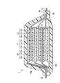
- FIG. 1 is a schematic cross-sectional view showing an example of a lithium ion secondary battery according to an embodiment of the present invention.
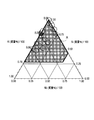
- FIG. 2 is a plot of each example in the composition diagram of the Si—Al—Nb ternary alloy, 0.27 ⁇ Si (mass% / 100) ⁇ 1.00, 0.00 ⁇ Al (mass% / 100) ⁇ 0.73, 0.00 ⁇ Nb (mass% / 100) ⁇ 0.58.
- FIG. 1 is a schematic cross-sectional view showing an example of a lithium ion secondary battery according to an embodiment of the present invention.
- FIG. 2 is a plot of each example in the composition diagram of the Si—Al—Nb ternary alloy, 0.27 ⁇ Si (mass% / 100) ⁇ 1.00, 0.00 ⁇ Al (mass% / 100) ⁇ 0.73, 0.00 ⁇ Nb (mass% / 100) ⁇ 0.58.
- FIG. 1 is a schematic cross-sectional view
- FIG. 3 is a plot of each example in the composition diagram of the Si—Al—Nb ternary alloy, 0.47 ⁇ Si (mass% / 100) ⁇ 0.95, 0.02 ⁇ Al (mass% / 100) ⁇ 0.48, 0.01 ⁇ Nb (mass% / 100) ⁇ 0.23.
- FIG. 1 is a plot of each example in the composition diagram of the Si—Al—Nb ternary alloy, 0.47 ⁇ Si (mass% / 100) ⁇ 0.95, 0.02 ⁇ Al (mass% / 100) ⁇ 0.48, 0.01 ⁇ Nb (mass% / 100) ⁇ 0.23.
- the negative electrode active material for electric devices of the present invention the negative electrode for electric devices using the same, and the electric device will be described in detail.
- a negative electrode active material for an electric device, a negative electrode for an electric device, and an electric device will be described by taking a lithium ion secondary battery as an example of an electric device to which the negative electrode active material can be applied as an example.
- the dimensional ratios in the drawings are exaggerated for convenience of explanation, and may differ from actual ratios.
- the negative electrode active material of the present embodiment includes more than 27 mass% and less than 100 mass% silicon (Si), more than 0 mass% and less than 73 mass% aluminum (Al), and more than 0 mass% and less than 58 mass% niobium ( Nb) and the balance is an inevitable impurity alloy.
- This numerical range corresponds to the range indicated by the symbol A in FIG.
- a lithium ion secondary battery can exhibit excellent cycle characteristics while maintaining a high discharge capacity as compared with a carbon-based negative electrode active material having a charge / discharge capacity of about 300 mAh / g.
- a lithium ion secondary battery It is suitably used for a negative electrode.
- it can be suitably used as a lithium-ion secondary battery for vehicle drive power or auxiliary power.
- the present invention can be sufficiently applied to lithium ion secondary batteries for portable devices such as mobile phones.
- the alloy absorbs lithium ions when the battery is charged and releases lithium ions when discharged.
- the negative electrode active material contains aluminum (Al) as a first additive element that suppresses amorphous-crystal phase transition and improves cycle life when alloyed with lithium by charging. Further, it contains niobium (Nb) as a second additive element that makes it difficult to reduce the capacitance as an electrode even if the concentration of the first additive element is increased.
- the negative electrode active material of the Si (Si—Al—Nb-based) alloy according to this embodiment can exhibit high capacity, high cycle durability, and high charge / discharge efficiency in the initial stage. Can do.
- the negative electrode active material made of a Si—Al—Nb-based alloy a sufficient initial capacity may not be obtained when the silicon content is 27% by mass or less, and conversely, when the silicon content is 100% by mass. Can obtain only the same cycle characteristics as in the case of conventional pure silicon.
- the cycle characteristics are equivalent to pure silicon when the content is 0% by mass, and conversely, when the content is 73% by mass or more, the silicon content is relatively decreased, the initial capacity is There is a tendency to deteriorate compared with existing negative electrode active materials.
- the cycle characteristics are equivalent to that of pure silicon, and conversely, when the content is 58% by mass or more, the silicon content decreases, so the initial capacity is the existing negative electrode. There is a tendency to get worse compared to the active material.
- the alloy has an Si content of more than 47% by mass and less than 95% by mass, an Al content of more than 2% by mass and less than 48% by mass, and Nb content. It is preferable that the amount is more than 1% by mass and less than 23% by mass and the balance is inevitable impurities. That is, this numerical range corresponds to the range indicated by the symbol B in FIG.
- the alloy has an Si content of more than 61% by mass and less than 84% by mass, an Al content of more than 2% by mass and less than 25% by mass, and Nb content.
- the amount is preferably more than 2% by mass and less than 23% by mass, and the balance is inevitable impurities. This numerical range corresponds to the range indicated by the symbol C in FIG.
- the Si content is more than 47% by mass and less than 56% by mass
- the Al content is more than 33% by mass and less than 48% by mass
- the Nb content is more than 1% by mass and less than 16% by mass
- the inevitable impurities may vary depending on the raw materials and the production method, but the content thereof is preferably less than 0.5% by mass, for example, and more preferably less than 0.1% by mass.
- the alloy contained in the negative electrode active material of the present embodiment is, as described above, more than 27 mass% and less than 100 mass% silicon, more than 0 mass% and less than 73 mass% aluminum, and more than 0 mass% and more than 58 mass%. % Of niobium and the balance is inevitable impurities. Therefore, in other words, the alloy consists of more than 27% by mass of silicon and less than 100% by mass of silicon, more than 0% by mass of less than 73% by mass of aluminum, more than 0% by mass of less than 58% by mass of niobium, and inevitable impurities. Is.
- an alloy in a thin film state can be cited.
- a method for producing such an alloy for example, a multi-source physical vapor deposition method (multi-source PVD method) such as a sputtering method, a resistance heating method, or a laser ablation method, or a multi-source chemical vapor deposition method such as a chemical vapor deposition method ( Multi-source CVD method).
- multi-source PVD method multi-source physical vapor deposition method
- a sputtering method such as a sputtering method, a resistance heating method, or a laser ablation method
- a multi-source chemical vapor deposition method such as a chemical vapor deposition method ( Multi-source CVD method).
- the negative electrode active material such as a binder and a conductive additive. Therefore, it is excellent in the viewpoint that the high capacity
- an independently controlled ternary DC magnetron sputtering apparatus can be used as a multi-element DC magnetron sputtering apparatus.
- a thin film of a silicon alloy containing a predetermined amount of Si, Al, and Nb with various alloy compositions and thicknesses can be freely formed on the surface of the substrate serving as a current collector.
- various alloys can be obtained by setting the target 1 to silicon (Si), the target 2 to aluminum (Al), the target 3 to niobium (Nb), fixing the sputtering time, and changing the power of the DC power source. it can.
- various alloys can be obtained by changing the power of the DC power source to 185 W for silicon (Si), 30 to 120 W for aluminum (Al), 60 to 120 W for niobium (Nb), and the like.
- the power of the DC power source to 185 W for silicon (Si), 30 to 120 W for aluminum (Al), 60 to 120 W for niobium (Nb), and the like.
- the sputtering conditions differ for each sputtering apparatus, it is desirable to appropriately grasp a suitable range through preliminary experiments for each sputtering apparatus.
- the Si—Al—Nb alloy thin film can be used for the negative electrode active material layer of the present embodiment.
- the negative electrode active material layer can also be a layer containing particles of the Si—Al—Nb alloy. That is, as another example of the negative electrode active material for a lithium ion secondary battery according to the present embodiment, for example, an alloy in a particle form can be cited.
- Examples of a method for producing such a particle-shaped alloy include a mechanical alloy method and an arc plasma melting method. Particles obtained by such a production method can be prepared by adding a binder, a conductive aid, a viscosity adjusting solvent, etc. to prepare a slurry, and applying this slurry to a current collector to form a negative electrode.
- This production method is superior to the above-described method for producing an alloy thin film in that it is easy to mass-produce and is practically used as an actual battery electrode.
- the manufacturing method of the negative electrode active material for a lithium ion secondary battery is not limited to these, and various conventionally known manufacturing methods can be applied. That is, since there is almost no difference in the alloy state and characteristics depending on the manufacturing method, various manufacturing methods can be applied.
- FIG. 1 is a schematic cross-sectional view showing an example of a lithium ion secondary battery according to an embodiment of the present invention.
- the lithium ion secondary battery 1 of this embodiment has a configuration in which a battery element 10 to which a positive electrode tab 21 and a negative electrode tab 22 are attached is enclosed in an exterior body 30.
- the positive electrode tab 21 and the negative electrode tab 22 are led out in the opposite direction from the inside of the exterior body 30 to the outside.
- the positive electrode tab and the negative electrode tab may be led out in the same direction from the inside of the exterior body toward the outside.
- such a positive electrode tab and a negative electrode tab can be attached to the positive electrode collector and negative electrode collector which are mentioned later by ultrasonic welding, resistance welding, etc., for example.
- the positive electrode tab 21 and the negative electrode tab 22 are made of materials such as aluminum, copper, titanium, nickel, stainless steel (SUS), and alloys thereof. However, the material is not limited to these, and a conventionally known material used as a tab for a lithium ion secondary battery can be used.
- the positive electrode tab and the negative electrode tab may be made of the same material or different materials. Further, as in the present embodiment, a separately prepared tab may be connected to a positive electrode current collector and a negative electrode current collector described later, and each positive electrode current collector and each negative electrode current collector described later are extended. A tab may be formed. Although not shown, the positive electrode tab 21 and the negative electrode tab 22 taken out from the outer package 30 are preferably covered with a heat-shrinkable heat-shrinkable tube or the like. Thereby, the possibility that the positive electrode tab 21 and the negative electrode tab 22 may contact a peripheral device, wiring, or the like to cause an electric leakage, thereby affecting products (for example, automobile parts, particularly electronic devices) is reduced.
- a current collector plate may be used for the purpose of taking out the current outside the battery.
- the current collector plate is electrically connected to the current collector and leads, and is taken out of the laminate sheet as the exterior body 30.
- the material which comprises a current collector plate is not specifically limited, The well-known highly electroconductive material conventionally used as a current collector plate for lithium ion secondary batteries can be used.
- As a constituent material of the current collector plate for example, metal materials such as aluminum, copper, titanium, nickel, stainless steel (SUS), and alloys thereof are preferable, and aluminum and aluminum are more preferable from the viewpoint of light weight, corrosion resistance, and high conductivity. Copper or the like is preferable.
- the same material may be used for a positive electrode current collecting plate and a negative electrode current collecting plate, and a different material may be used.
- the exterior body 30 is preferably formed of a film-shaped exterior material from the viewpoint of size reduction and weight reduction.
- the conventionally well-known material used for the exterior body for lithium ion secondary batteries can be used. That is, a metal can case can also be applied.
- a polymer-metal composite laminate sheet having excellent thermal conductivity is used from the viewpoint that it has high output and excellent cooling performance and can be suitably used for batteries for large equipment of electric vehicles and hybrid electric vehicles.
- an exterior body formed of an exterior material such as a laminate film having a three-layer structure in which PP, aluminum, and nylon are laminated in this order can be applied.
- the battery element 10 includes both a positive electrode 11 having a positive electrode active material layer 11b formed on both main surfaces of the positive electrode current collector 11a, an electrolyte layer 13, and a negative electrode current collector 12a.
- a plurality of negative electrodes 12 each having a negative electrode active material layer 12b formed on the main surface are stacked.
- the formed negative electrode active material layer 12 b faces through the electrolyte layer 13.
- a plurality of positive electrodes, electrolyte layers, and negative electrodes are laminated in this order.
- the adjacent positive electrode active material layer 11b, the electrolyte layer 13, and the negative electrode active material layer 12b constitute one unit cell layer. Therefore, the lithium ion secondary battery 1 of the present embodiment has a configuration in which a plurality of single battery layers 14 are stacked and electrically connected in parallel.
- the negative electrode current collector 12 a located in the outermost layer of the battery element 10 has a negative electrode active material layer 12 b formed only on one side.
- an insulating layer may be provided on the outer periphery of the unit cell layer in order to insulate between the adjacent positive electrode current collector and negative electrode current collector.
- Such an insulating layer is preferably formed on the outer periphery of the unit cell layer by a material that holds the electrolyte contained in the electrolyte layer and prevents the electrolyte from leaking.
- general-purpose plastics such as polypropylene (PP), polyethylene (PE), polyurethane (PUR), polyamide resin (PA), polytetrafluoroethylene (PTFE), polyvinylidene fluoride (PVdF), polystyrene (PS), etc.
- thermoplastic olefin rubber can be used. Silicone rubber can also be used.
- the positive electrode current collector 11a and the negative electrode current collector 12a are made of a conductive material.
- the size of the current collector can be determined according to the intended use of the battery. For example, if it is used for a large battery that requires a high energy density, a current collector having a large area is used. There is no particular limitation on the thickness of the current collector.
- the thickness of the current collector is usually about 1 to 100 ⁇ m.
- the shape of the current collector is not particularly limited. In the battery element 10 shown in FIG. 1, in addition to the current collector foil, a mesh shape (expanded grid or the like) can be used.
- a mesh shape expansion grid or the like
- a metal or a resin in which a conductive filler is added to a conductive polymer material or a non-conductive polymer material can be employed.
- the metal include aluminum, nickel, iron, stainless steel, titanium, and copper.
- covered on the metal surface may be sufficient.
- aluminum, stainless steel, copper, and nickel are preferable from the viewpoints of electronic conductivity, battery operating potential, and adhesion of the negative electrode active material by sputtering to the current collector.
- the conductive polymer material examples include polyaniline, polypyrrole, polythiophene, polyacetylene, polyparaphenylene, polyphenylene vinylene, polyacrylonitrile, and polyoxadiazole. Since such a conductive polymer material has sufficient conductivity without adding a conductive filler, it is advantageous in terms of facilitating the manufacturing process or reducing the weight of the current collector.
- Non-conductive polymer materials include, for example, polyethylene (PE; high density polyethylene (HDPE), low density polyethylene (LDPE), etc.), polypropylene (PP), polyethylene terephthalate (PET), polyether nitrile (PEN), polyimide (PI), polyamideimide (PAI), polyamide (PA), polytetrafluoroethylene (PTFE), styrene-butadiene rubber (SBR), polyacrylonitrile (PAN), polymethyl acrylate (PMA), polymethyl methacrylate (PMMA) , Polyvinyl chloride (PVC), polyvinylidene fluoride (PVdF), polystyrene (PS), and the like.
- PE polyethylene
- HDPE high density polyethylene
- LDPE low density polyethylene
- PP polypropylene
- PET polyethylene terephthalate
- PEN polyether nitrile
- PI polyimide
- PAI polyamideimide
- PA polyamide
- PTFE polyt
- a conductive filler can be added to the conductive polymer material or the non-conductive polymer material as necessary.
- a conductive filler is essential to impart conductivity to the resin.
- the conductive filler can be used without particular limitation as long as it is a substance having conductivity.
- a metal, conductive carbon, etc. are mentioned as a material excellent in electroconductivity, electric potential resistance, or lithium ion interruption
- the metal is not particularly limited, but includes at least one metal selected from the group consisting of Ni, Ti, Al, Cu, Pt, Fe, Cr, Sn, Zn, In, Sb, and K, or these metals.
- the conductive carbon is not particularly limited, but preferably acetylene black, Vulcan (registered trademark), black pearl (registered trademark), carbon nanofiber, ketjen black (registered trademark), carbon nanotube, carbon nanohorn, carbon It contains at least one selected from the group consisting of nanoballoons and fullerenes.
- the amount of the conductive filler added is not particularly limited as long as it is an amount capable of imparting sufficient conductivity to the current collector, and is generally about 5 to 35% by mass of the entire current collector.
- the material is not limited to these, and a conventionally known material used as a current collector for a lithium ion secondary battery can be used.
- the negative electrode active material according to this embodiment contains a Si—Al—Nb alloy having the above-described composition as an essential component.
- the negative electrode active material layer 12b according to this embodiment may be a thin film made of the Si—Al—Nb alloy.
- the negative electrode active material layer 12b may be formed of only the Si—Al—Nb alloy, or may contain other negative electrode active materials described later.
- the negative electrode active material layer 12b may be a layer containing particles of the Si—Al—Nb alloy as a main component.
- the negative electrode active material layer 12b may contain a conductive additive or a binder.
- the “main component” refers to a component having a content of 50% by mass or more in the negative electrode active material layer 12b.
- a negative electrode active material made of a Si—Al—Nb alloy having the above composition is used.
- the negative electrode active material made of such an alloy is contained as an essential component, there is no problem in using a conventionally known negative electrode active material capable of reversibly occluding and releasing lithium.
- negative electrode active materials include, for example, graphite (natural graphite, artificial graphite, etc.) which is highly crystalline carbon, low crystalline carbon (soft carbon, hard carbon), carbon black (Ketjen Black (registered trademark), acetylene) Black, channel black, lamp black, oil furnace black, thermal black, etc.), fullerenes, carbon nanotubes, carbon nanofibers, carbon nanohorns, carbon fibrils, and the like.
- a negative electrode active material Si, Ge, Sn, Pb, Al, In, Zn, H, Ca, Sr, Ba, Ru, Rh, Ir, Pd, Pt, Ag, Au, Cd, Hg, Ga
- examples thereof include simple elements such as Tl, C, N, Sb, Bi, O, S, Se, Te, and Cl that are alloyed with lithium, oxides and carbides containing these elements, and the like.
- oxides include silicon monoxide (SiO), SiOx (0 ⁇ x ⁇ 2), tin dioxide (SnO 2 ), SnO x (0 ⁇ x ⁇ 2), SnSiO 3 and the like.
- the carbide include silicon carbide (SiC).
- examples of the negative electrode active material include metal materials such as lithium metal and lithium-transition metal composite oxides such as lithium-titanium composite oxide (lithium titanate: Li 4 Ti 5 O 12 ).
- metal materials such as lithium metal and lithium-transition metal composite oxides such as lithium-titanium composite oxide (lithium titanate: Li 4 Ti 5 O 12 ).
- lithium-titanium composite oxide lithium titanate: Li 4 Ti 5 O 12
- the conventionally well-known material used as a negative electrode active material for lithium ion secondary batteries can be used. These negative electrode active materials may be used alone or in combination of two or more.
- the binder is not particularly limited, and examples thereof include the following materials.
- polyethylene PE
- polypropylene PP
- PET polyethylene terephthalate
- PEN polyether nitrile
- PAN polyacrylonitrile
- PA polyamide
- CMC carboxymethyl cellulose
- PVC polyvinyl chloride
- SBR styrene / butadiene rubber
- isoprene rubber butadiene rubber
- ethylene / propylene rubber ethylene / propylene / diene copolymer
- styrene / butadiene / styrene block copolymer examples thereof include thermoplastic polymers such as a polymer and a hydrogenated product thereof, a styrene / isoprene / styrene block copolymer and a hydrogenated product thereof.
- PVDF Polyvinylidene fluoride
- PTFE polytetrafluoroethylene
- FEP tetrafluoroethylene / hexafluoropropylene copolymer
- PFA tetrafluoroethylene / perfluoroalkyl vinyl ether copolymer
- fluorine resins such as ethylene copolymer (ETFE), polychlorotrifluoroethylene (PCTFE), ethylene / chlorotrifluoroethylene copolymer (ECTFE), and polyvinyl fluoride (PVF).
- VDF-HFP-based fluorubber vinylidene fluoride-hexafluoropropylene-based fluororubber
- VDF-HFP-TFE-based fluororubber vinylidene fluoride- Pentafluoropropylene-based fluororubber
- VDF-PFP-based fluorubber vinylidene fluoride-pentafluoropropylene-tetrafluoroethylene-based fluororubber
- VDF-PFP-TFE-based fluorubber vinylidene fluoride-perfluoromethylvinylether-tetra Fluoroethylene-based fluororubber
- VDF-PFMVE-TFE-based fluorubber vinylidene fluoride-chlorotrifluoroethylene-based fluororubber
- polyvinylidene fluoride, polyimide, styrene / butadiene rubber, carboxymethyl cellulose, polypropylene, polytetrafluoroethylene, polyacrylonitrile, and polyamide are more preferable. Since these suitable binders are excellent in heat resistance, have a very wide potential window, and are stable at both the positive electrode potential and the negative electrode potential, they can be used for the negative electrode active material layer and the positive electrode active material layer.
- the material is not limited to these, and a known material conventionally used as a binder for a lithium ion secondary battery can be used. These binders may be used alone or in combination of two or more.
- the amount of the binder contained in the negative electrode active material layer 12b is not particularly limited as long as it is an amount capable of binding the negative electrode active material.
- the amount of the binder is preferably 0.5 to 15% by mass, more preferably 1 to 10% by mass with respect to the negative electrode active material layer.
- the conductive auxiliary agent is blended in order to improve the conductivity of the negative electrode active material layer.
- a conductive support agent carbon materials, such as carbon black, such as acetylene black, a graphite, and a vapor growth carbon fiber, can be mentioned, for example. If the negative electrode active material layer contains a conductive additive, an electronic network inside the negative electrode active material layer is effectively formed, which can contribute to improvement of the output characteristics of the battery.
- the conductive auxiliary agent is not limited to these, and a conventionally known material used as a conductive auxiliary agent for a lithium ion secondary battery can be used. These conductive assistants may be used alone or in combination of two or more.
- the conductive binder having the functions of the conductive assistant and the binder may be used instead of the conductive assistant and the binder, or may be used in combination with one or both of the conductive assistant and the binder.
- the conductive binder for example, commercially available TAB-2 manufactured by Hosen Co., Ltd. can be used.
- the positive electrode active material layer 11b includes any one or more of positive electrode materials capable of inserting and extracting lithium as a positive electrode active material, and includes a binder and a conductive auxiliary agent as necessary. May be. In addition, what was demonstrated above can be used for a binder and a conductive support agent.
- a lithium-containing compound is preferable from the viewpoint of capacity and output characteristics.
- lithium-containing compounds include composite oxides containing lithium and transition metal elements, phosphate compounds containing lithium and transition metal elements, sulfate compounds containing lithium and transition metal elements, and lithium and transition metals. Examples include solid solutions containing elements. From the viewpoint of obtaining higher capacity and output characteristics, lithium-transition metal composite oxides are particularly preferable.
- the composite oxide containing lithium and a transition metal element include lithium cobalt composite oxide (LiCoO 2 ), lithium nickel composite oxide (LiNiO 2 ), lithium nickel cobalt composite oxide (LiNiCoO 2 ), and lithium nickel.
- the phosphate compound containing lithium and a transition metal element include a lithium iron phosphate compound (LiFePO 4 ) and a lithium iron manganese phosphate compound (LiFeMnPO 4 ).
- LiFePO 4 lithium iron phosphate compound
- LiFeMnPO 4 lithium iron manganese phosphate compound
- a part of the transition metal may be substituted with another element.
- sulfuric acid compound containing lithium and a transition metal element include Li x Fe 2 (SO 4 ) 3 and the like.
- Solid solution containing lithium and a transition metal element examples include xLiM I O 2.
- a positive electrode active material other than those described above may be used.
- lithium metal may be used.
- each positive electrode active material layer 11b and negative electrode active material layer 12b active material layer on one side of the current collector
- the thickness of each active material layer is usually about 1 to 500 ⁇ m, preferably 2 to 100 ⁇ m, taking into consideration the intended use of the battery (emphasis on output, energy, etc.) and ion conductivity.
- the optimum particle size when the optimum particle size is different for expressing the unique effect of each active material, the optimum particle size may be mixed and used for expressing each unique effect. Therefore, it is not necessary to make the particle sizes of all the active materials uniform.
- the average particle size of the alloy is approximately the same as the average particle size of the negative electrode active material included in the existing negative electrode active material layer Well, not particularly limited. From the viewpoint of higher output, it is preferably in the range of 1 to 20 ⁇ m.
- the “particle diameter” refers to the outline of active material particles (observation surface) observed using an observation means such as a scanning electron microscope (SEM) or a transmission electron microscope (TEM). It means the maximum distance among any two points.
- the value of “average particle size” is the average value of the particle size of particles observed in several to several tens of fields using an observation means such as a scanning electron microscope (SEM) or a transmission electron microscope (TEM). The calculated value shall be adopted.
- the particle diameters and average particle diameters of other components can be defined in the same manner.
- the particle diameter is not limited to such a range, and may be outside this range as long as the effects of the present embodiment can be expressed effectively.
- electrolyte layer 13 As electrolyte layer 13, what formed the layer structure using the electrolyte solution hold
- the electrolyte solution is preferably one used in, for example, a lithium ion secondary battery, and specifically has a configuration in which a supporting salt (lithium salt) is dissolved in an organic solvent.
- a supporting salt lithium salt
- the lithium salt LiPF 6, LiBF 4, LiClO 4, LiAsF 6, LiTaF 6, LiAlCl 4, Li 2 B 10 Cl 10 inorganic acid anion salts such as, LiCF 3 SO 3, Li ( CF 3 SO 2 ) 2 N, at least one lithium salt selected from organic acid anion salts such as Li (C 2 F 5 SO 2 ) 2 N, and the like.
- organic solvent examples include cyclic carbonates such as propylene carbonate (PC) and ethylene carbonate (EC); chain carbonates such as dimethyl carbonate (DMC), methyl ethyl carbonate (EMC), and diethyl carbonate (DEC).
- cyclic carbonates such as propylene carbonate (PC) and ethylene carbonate (EC)
- chain carbonates such as dimethyl carbonate (DMC), methyl ethyl carbonate (EMC), and diethyl carbonate (DEC).
- Ethers such as tetrahydrofuran, 2-methyltetrahydrofuran, 1,4-dioxane, 1,2-dimethoxyethane, 1,2-dibutoxyethane; lactones such as ⁇ -butyrolactone; nitriles such as acetonitrile; methyl propionate Esters such as amides; Amides such as dimethylformamide; One using at least one selected from methyl acetate and methyl formate, or a mixture using an organic solvent such as an aprotic solvent can be used. .
- the microporous film which consists of polyolefin, such as polyethylene and a polypropylene, a porous flat plate, and also a nonwoven fabric can be mentioned, for example.
- polymer gel electrolyte examples include those containing a polymer constituting the polymer gel electrolyte and an electrolytic solution in a conventionally known ratio. From the viewpoint of ionic conductivity and the like, the polymer content in the polymer gel electrolyte is preferably about several mass% to 98 mass%, for example.
- the polymer gel electrolyte is obtained by adding the above-described electrolytic solution normally used in a lithium ion secondary battery to a solid polymer electrolyte having ion conductivity.
- the present invention is not limited to this, and includes a structure in which a similar electrolyte solution is held in a polymer skeleton having no lithium ion conductivity.
- PVdF polyvinylidene fluoride
- PVC polyvinyl chloride
- PAN polyacrylonitrile
- PMMA polymethyl methacrylate
- the solid polymer electrolyte examples include a structure in which the lithium salt is dissolved in polyethylene oxide (PEO), polypropylene oxide (PPO), and the like, and does not contain an organic solvent. Therefore, when the electrolyte layer is composed of a solid polymer electrolyte, there is no fear of liquid leakage from the battery, and the battery reliability can be improved.
- PEO polyethylene oxide
- PPO polypropylene oxide
- the thickness of the electrolyte layer is preferably thinner from the viewpoint of reducing internal resistance.
- the thickness of the electrolyte layer is usually 1 to 100 ⁇ m, preferably 5 to 50 ⁇ m.
- the matrix polymer of the polymer gel electrolyte or the solid polymer electrolyte can express excellent mechanical strength by forming a crosslinked structure.
- thermal polymerization, ultraviolet polymerization, radiation polymerization, electron beam polymerization, etc. are performed on a polymerizable polymer (for example, PEO or PPO) for forming a polymer electrolyte using an appropriate polymerization initiator.
- a polymerization treatment may be performed.
- a positive electrode is produced. For example, when using a granular positive electrode active material, a positive electrode active material and a conductive support agent, a binder, and a viscosity adjusting solvent are mixed as needed to produce a positive electrode slurry. Next, this positive electrode slurry is applied to a positive electrode current collector, dried, and compression molded to form a positive electrode active material layer.
- a negative electrode For example, when using a granular negative electrode active material, a negative electrode active material and a conductive support agent, a binder, and a viscosity adjusting solvent are mixed as needed, and a negative electrode slurry is produced. Thereafter, this negative electrode slurry is applied to a negative electrode current collector, dried and compression molded to form a negative electrode active material layer.
- the positive electrode tab is attached to the positive electrode
- the negative electrode tab is attached to the negative electrode
- the positive electrode, the separator, and the negative electrode are laminated.
- the laminated product is sandwiched between polymer-metal composite laminate sheets, and the outer peripheral edge except for one side is heat-sealed to form a bag-like outer package.
- a non-aqueous electrolyte containing a lithium salt such as lithium hexafluorophosphate and an organic solvent such as ethylene carbonate is prepared and injected into the interior through the opening of the exterior body, and the opening of the exterior body is thermally melted. Wear and enclose. Thereby, a laminate-type lithium ion secondary battery is completed.
- Sputtering conditions (1) Base pressure: up to 7 ⁇ 10 ⁇ 6 Pa (2) Sputtering gas type: Ar (99.9999% or more) (3) Sputter gas introduction amount: 10 sccm (4) Sputtering pressure: 30 mTorr (5) DC power supply: Si (185 W), Al (30 to 120 W), Nb (60 to 120 W) (6) Pre-sputtering time: 1 min (7) Sputtering time: 10 min (8) Substrate heating: Room temperature (25 ° C)
- Substrate to be a current collector Ni foil (thickness: 20 ⁇ m)
- Sputtered film thickness: Si was always 100 nm, and the amount of additive elements (Al, Nb) was appropriately changed for each sputtering power. Specifically, the DC power supply was changed for each sputtering power so that the additive element concentration increased with increasing additive element (Al, Nb) concentration.
- the composition ratio (mass%) of the alloy was as shown in Table 1. That is, Si target, Al target, and Nb target were used, the sputtering time was fixed, and the power of the DC power source was changed within the above range. Thus, an amorphous alloy thin film was formed on the Ni substrate, and various alloy samples were obtained as evaluation electrodes.
- Example 5 the DC power source 1 (Si target) was 185 W, the DC power source 2 (Al target) was 60 W, and the DC power source 3 (Nb target) was 90 W.
- the DC power source 1 (Si target) was 185 W
- the DC power source 2 (Al target) was 72 W
- the DC power source 3 (Nb target) was 0 W.
- the DC power source 1 (Si target) was 185 W
- the DC power source 2 (Al target) was 0 W
- the DC power source 3 (Nb target) was 55 W.
- an evaluation cell (CR 2032 type coin cell) was created by combining the evaluation electrode with a Li foil (counter electrode), a separator, and an electrolytic solution.
- a Li foil counter electrode
- a separator separator
- electrolytic solution A part of the specification of each example is shown in Table 1.
- discharge capacity retention rate after 50 cycles (%) means the ratio of the discharge capacity at the 50th cycle to the discharge capacity at the first cycle ((discharge capacity at the 50th cycle) / (first cycle). Discharge capacity) ⁇ 100).
- discharge capacity retention rate after 100 cycles (%) is the ratio of the discharge capacity at the 100th cycle to the discharge capacity at the first cycle ((discharge capacity at the 100th cycle) / (first cycle). Discharge capacity) ⁇ 100).
- the charge / discharge capacity was calculated based on the weight of the alloy. The obtained results are also shown in Table 1.
- the silicon content is more than 27% by mass and less than 100% by mass
- the aluminum content is more than 0% by mass and less than 73% by mass
- the niobium content is more than 0% by mass 58%.
- An alloy having less than mass% and the balance being inevitable impurities is shown. From Table 1, the lithium ion secondary battery using this alloy exhibits excellent cycle characteristics while maintaining a high discharge capacity as compared with a carbon-based negative electrode active material having a charge / discharge capacity of about 300 mAh / g. I understand that.
- the range of the symbol B in FIG. 3 is that the silicon content is more than 47 mass% and less than 95 mass%, the aluminum content is more than 2 mass% and less than 48 mass%, and the niobium content is 1 mass.
- the range of symbol B corresponds to the first to eleventh embodiments. From Table 1, it can be seen that a lithium ion secondary battery using this alloy is particularly excellent in discharge capacity retention after 50 cycles.
- the range of the symbol C in FIG. 4 is that the silicon content is more than 61% by mass and less than 84% by mass, the aluminum content is more than 2% by mass and less than 25% by mass, and the niobium content is 2% by mass.
- the range indicated by the symbol C in FIG. 4 corresponds to the second to sixth embodiments.
- the range of D in FIG. 4 is that the silicon content is more than 47 mass% and less than 56 mass%, the aluminum content is more than 33 mass% and less than 48 mass%, and the niobium content is 1 mass.
- An alloy whose content is more than% and less than 16% by mass and the balance is an inevitable impurity. 4 corresponds to the eighth to eleventh embodiments. From Table 1. In particular, it can be seen that the lithium ion secondary battery using the alloy in the range of C and D has an excellent discharge capacity retention rate after 100 cycles.
- the lithium ion secondary battery is exemplified as the electric device.
- the present invention is not limited to this, and can be applied to other types of secondary batteries and further to primary batteries. . Further, it can be applied not only to a battery but also to a capacitor.
- the negative electrode for an electric device and the electric device of the present invention are not particularly limited as long as they include a predetermined alloy as a negative electrode active material.
- a battery element in a bipolar battery generally includes a bipolar electrode in which a negative electrode active material layer is formed on one surface of a current collector and a positive electrode active material layer is formed on the other surface, an electrolyte layer, A plurality of layers.
- a silicon alloy containing a predetermined amount of Si, Al, and Nb was used as the negative electrode active material for an electrical device. Therefore, it is possible to provide a negative electrode active material for an electric device such as a lithium ion secondary battery that can exhibit excellent cycle characteristics while maintaining a high discharge capacity, and a negative electrode for an electric device and an electric device using the same.
Landscapes
- Chemical & Material Sciences (AREA)
- Engineering & Computer Science (AREA)
- Chemical Kinetics & Catalysis (AREA)
- Electrochemistry (AREA)
- General Chemical & Material Sciences (AREA)
- Materials Engineering (AREA)
- Organic Chemistry (AREA)
- Mechanical Engineering (AREA)
- Metallurgy (AREA)
- Power Engineering (AREA)
- Manufacturing & Machinery (AREA)
- Microelectronics & Electronic Packaging (AREA)
- Battery Electrode And Active Subsutance (AREA)
- Electric Double-Layer Capacitors Or The Like (AREA)
- Secondary Cells (AREA)
Abstract
本発明の電気デバイス用負極活物質は、27質量%超100質量%未満のケイ素と、0質量%超73質量%未満のアルミニウムと、0質量%超58質量%未満のニオブとを含有し、残部が不可避不純物である合金を有する。当該負極活物質は、例えば、ケイ素、アルミニウム及びニオブをターゲットとして、多元DCマグネトロンスパッタ装置を用いることにより得ることができる。そして、当該負極活物質を適用した電気デバイスは、高い放電容量を維持しつつ、優れたサイクル特性を発揮し得る。
Description
本発明は、電気デバイス用負極活物質、電気デバイス用負極及び電気デバイスに関する。更に詳細には、本発明の電気デバイスは、例えば、二次電池やキャパシタ等として電気自動車、燃料電池自動車及びハイブリッド電気自動車等の車両におけるモータ等の駆動用電源や補助電源に用いられる。
近年、大気汚染や地球温暖化に対処するため、二酸化炭素排出量の低減が切に望まれている。そして、自動車業界では、電気自動車(EV)やハイブリッド電気自動車(HEV)の導入による二酸化炭素排出量の低減に期待が集まっている。そのため、これらの実用化の鍵となるモータ駆動用二次電池などの電気デバイスの開発が盛んに行われている。
モータ駆動用二次電池としては、高い理論エネルギーを有するリチウムイオン二次電池が注目を集めており、現在急速に開発が進められている。リチウムイオン二次電池は、一般に、正極活物質を含む正極スラリを集電体の表面に塗布して形成した正極と、負極活物質を含む負極スラリを集電体の表面に塗布して形成した負極と、これらの間に位置する電解質層とを備える。そして、リチウムイオン二次電池は、これら正極、負極及び電解質層が電池ケースに収納された構成を有する。
そして、リチウムイオン二次電池の容量特性、出力特性などの向上のためには、各活物質の選定が極めて重要となる。
従来、高い放電容量を維持しつつ、優れたサイクル特性を発揮するリチウム二次電池用負極材料として、特許文献1に記載の材料が提案されている。特許文献1のリチウム二次電池用負極材料は、複数種の金属成分や、微細炭素材料からなる炭素成分などで構成され、所定の粒径を有する複合粉末からなる材料である。
しかしながら、本発明者らの検討した結果、特許文献1に記載のリチウム二次電池用負極材料は、放電容量及びサイクル特性が十分なものとなっていないという問題点があった。
本発明は、このような従来技術の有する課題に鑑みてなされたものである。そして、その目的は、高い放電容量を維持しつつ、優れたサイクル特性を発揮し得る電気デバイス用負極活物質、これを用いた電気デバイス用負極及び電気デバイスを提供することにある。
本発明の態様に係る電気デバイス用負極活物質は、27質量%超100質量%未満のケイ素と、0質量%超73質量%未満のアルミニウムと、0質量%超58質量%未満のニオブとを含有し、残部が不可避不純物である合金を有する。
以下、本発明の電気デバイス用負極活物質、これを用いた電気デバイス用負極及び電気デバイスについて詳細に説明する。なお、説明の便宜上、上記負極活物質が適用され得る電気デバイスの一例であるリチウムイオン二次電池を例に挙げて、電気デバイス用負極活物質、電気デバイス用負極及び電気デバイスを説明する。また、図面の寸法比率は説明の都合上誇張されており、実際の比率とは異なる場合がある。
[リチウムイオン二次電池用負極活物質]
本発明の実施形態に係るリチウムイオン二次電池用負極活物質について詳細に説明する。
本発明の実施形態に係るリチウムイオン二次電池用負極活物質について詳細に説明する。
本実施形態の負極活物質は、27質量%超100質量%未満のケイ素(Si)と、0質量%超73質量%未満のアルミニウム(Al)と、0質量%超58質量%未満のニオブ(Nb)とを含有し、残部が不可避不純物である合金を有するものである。なお、この数値範囲は、図2の符号Aで示す範囲に相当する。
このような負極活物質は、充放電容量が約300mAh/gである炭素系の負極活物質に比べ、高い放電容量を維持しつつ、優れたサイクル特性を発揮し得るため、リチウムイオン二次電池用負極に好適に用いられる。その結果、車両の駆動電源用や補助電源用のリチウムイオン二次電池として好適に利用できる。このほかにも、携帯電話などの携帯機器向けのリチウムイオン二次電池にも十分に適用可能である。
より詳細に説明すると、上記負極活物質がリチウムイオン二次電池の負極に用いられる場合、上記合金は、電池の充電の際にリチウムイオンを吸収し、放電の際にリチウムイオンを放出する。そして、上記負極活物質は、充電によってリチウムと合金化する際に、アモルファス-結晶の相転移を抑制してサイクル寿命を向上させる第1添加元素としてのアルミニウム(Al)を含有する。さらに、この第1添加元素の濃度が増加しても電極としての容量を減少し難くする第2添加元素としてのニオブ(Nb)を含有する。これによって、本実施形態に係るSi(Si-Al-Nb系)合金の負極活物質は、高容量で、高サイクル耐久性を発揮することができ、さらに初期において高い充放電効率を発揮することができる。
なお、Si-Al-Nb系合金から成る上記負極活物質において、ケイ素含有量が27質量%以下の場合には十分な初期容量が得られない可能性があり、逆に100質量%の場合には従来の純ケイ素の場合と同じのサイクル特性しか得られない。また、アルミニウム含有量については、0質量%の場合にはサイクル特性が純ケイ素と同等になり、逆に73質量%以上の場合にはケイ素の含有量が相対的に低下するため、初期容量が既存の負極活物質と比べて悪化する傾向がある。一方、ニオブ含有量については、0質量%の場合にはサイクル特性が純ケイ素と同等になり、逆に58質量%以上の場合にはケイ素の含有量が低下するため、初期容量が既存の負極活物質と比べて悪化する傾向がある。
そして、より優れたサイクル特性を発揮し得るという観点から、前記合金は、Siの含有量が47質量%超95質量%未満、Alの含有量が2質量%超48質量%未満、Nbの含有量が1質量%超23質量%未満であり、残部が不可避不純物であることが好ましい。つまり、なお、この数値範囲は、図3の符号Bで示す範囲に相当する。
また、更に優れたサイクル特性を発揮し得るという観点から、前記合金は、Siの含有量が61質量%超84質量%未満、Alの含有量が2質量%超25質量%未満、Nbの含有量が2質量%超23質量%未満であり、残部が不可避不純物であることが好ましい。なお、この数値範囲は、図4の符号Cで示す範囲に相当する。
さらに、前記合金は、Siの含有量が47質量%超56質量%未満、Alの含有量が33質量%超48質量%未満、Nbの含有量が1質量%超16質量%未満であり、残部が不可避不純物である場合も、更に優れたサイクル特性を発揮し得るという観点から好ましい。なお、この数値範囲は、図4の符号Dで示す範囲に相当する。
なお、不可避不純物は、原料や製造方法により異なることがあるが、その含有量は、例えば0.5質量%未満であることが好ましく、0.1質量%未満であることがより好ましい。
ここで、本実施形態の負極活物質に含まれる合金は、上述のように27質量%超100質量%未満のケイ素と、0質量%超73質量%未満のアルミニウムと、0質量%超58質量%未満のニオブとを含有し、残部が不可避不純物である。そのため、言い換えれば、上記合金は、27質量%超100質量%未満のケイ素と、0質量%超73質量%未満のアルミニウムと、0質量%超58質量%未満のニオブと、不可避不純物のみからなるものである。
次に、上述した本実施形態のリチウムイオン二次電池用負極活物質の製造方法について説明する。
本実施形態のリチウムイオン二次電池用負極活物質の一例として、例えば、薄膜状態の合金を挙げることができる。このような合金の製造方法としては、例えば、スパッタ法、抵抗加熱法、レーザーアブレーション法などの多元物理気相蒸着法(多元PVD法)や、化学気相成長法のような多元化学蒸着法(多元CVD法)などを挙げることができる。これらの製造方法では、集電体となる基板上に合金薄膜を直接成膜して負極とすることができる。そのため、工程の簡略化及び簡素化を図ることができるという観点において優れている。更には、バインダや導電助剤などの負極活物質(合金)以外の成分を用いる必要がない。そのため、車両用途の実用化レベルを満足し得る高容量及び高エネルギー密度化を図ることができるという観点において優れている。
上記薄膜状態の合金の製造方法としては、例えば、多元DCマグネトロンスパッタ装置として、独立制御の三元DCマグネトロンスパッタ装置を用いることができる。これを用いると、集電体となる基板の表面に種々の合金組成及び厚さでSi、Al及びNbを所定量含んだケイ素合金の薄膜を自在に形成することができる。例えば、ターゲット1をケイ素(Si)、ターゲット2をアルミニウム(Al)、ターゲット3をニオブ(Nb)とし、スパッタ時間を固定し、DC電源のパワーをそれぞれ変化させることにより種々の合金を得ることができる。また、例えば、DC電源のパワーをケイ素(Si)では185W、アルミニウム(Al)では30から120W、ニオブ(Nb)では60から120Wなどのようにそれぞれ変化させることにより種々の合金を得ることができる。但し、スパッタ条件は、スパッタ装置ごとに異なるため、スパッタ装置ごとに予備実験などを通じて適宜好適な範囲を把握しておくことが望ましい。
ここで、上述のように、本実施形態の負極活物質層は、上記Si-Al-Nb系合金の薄膜を使用することができる。しかし、負極活物質層は、上記Si-Al-Nb系合金の粒子を含有する層とすることもできる。つまり、本実施形態のリチウムイオン二次電池用負極活物質の他の一例として、例えば、粒子形態の合金を挙げることもできる。
このような粒子形態の合金の製造方法としては、例えばメカニカルアロイ法やアークプラズマ溶融法などを挙げることができる。このような製造方法で得られた粒子は、バインダや導電助剤、粘度調整溶剤などを加えてスラリを調製し、このスラリを集電体に塗布して負極を形成することができる。この製造方法は、上述の合金薄膜の製造方法に比べて、大量生産し易く、実際の電池用電極として実用化し易いという観点において優れている。
リチウムイオン二次電池用負極活物質の製造方法としては、これらに限定されるものではなく、従来公知の各種の製造方法を適用することができる。つまり、製造方法による合金状態及び特性の違いはほとんどないので、各種の製造方法を適用することができる。
次に、本発明の実施形態に係るリチウムイオン二次電池用負極及びリチウムイオン二次電池について図面を参照しながら詳細に説明する。
[リチウムイオン二次電池の構成]
図1は、本発明の実施形態に係るリチウムイオン二次電池の一例を示す概略断面図である。図1に示すように、本実施形態のリチウムイオン二次電池1は、正極タブ21及び負極タブ22が取り付けられた電池要素10が外装体30の内部に封入された構成を有している。そして、本実施形態においては、正極タブ21及び負極タブ22が、外装体30の内部から外部に向かって、反対方向に導出されている。なお、図示しないが、正極タブ及び負極タブが、外装体の内部から外部に向かって、同一方向に導出されていてもよい。また、このような正極タブ及び負極タブは、例えば超音波溶接や抵抗溶接などにより後述する正極集電体及び負極集電体に取り付けることができる。
図1は、本発明の実施形態に係るリチウムイオン二次電池の一例を示す概略断面図である。図1に示すように、本実施形態のリチウムイオン二次電池1は、正極タブ21及び負極タブ22が取り付けられた電池要素10が外装体30の内部に封入された構成を有している。そして、本実施形態においては、正極タブ21及び負極タブ22が、外装体30の内部から外部に向かって、反対方向に導出されている。なお、図示しないが、正極タブ及び負極タブが、外装体の内部から外部に向かって、同一方向に導出されていてもよい。また、このような正極タブ及び負極タブは、例えば超音波溶接や抵抗溶接などにより後述する正極集電体及び負極集電体に取り付けることができる。
[正極タブ及び負極タブ]
正極タブ21及び負極タブ22は、例えば、アルミニウムや銅、チタン、ニッケル、ステンレス鋼(SUS)、これらの合金などの材料により構成されている。しかしながら、これらに限定されるものではなく、リチウムイオン二次電池用のタブとして用いられている従来公知の材料を用いることができる。
正極タブ21及び負極タブ22は、例えば、アルミニウムや銅、チタン、ニッケル、ステンレス鋼(SUS)、これらの合金などの材料により構成されている。しかしながら、これらに限定されるものではなく、リチウムイオン二次電池用のタブとして用いられている従来公知の材料を用いることができる。
なお、正極タブ及び負極タブは、同一材料のものを用いてもよく、異なる材料のものを用いてもよい。また、本実施形態のように、別途準備したタブを後述する正極集電体及び負極集電体に接続してもよいし、後述する各正極集電体及び各負極集電体をそれぞれ延長することによってタブを形成してもよい。なお、図示しないが、外装体30から取り出された部分の正極タブ21及び負極タブ22は、耐熱絶縁性の熱収縮チューブなどにより被覆することが好ましい。これにより、正極タブ21及び負極タブ22が周辺機器や配線などに接触して漏電することにより、製品(例えば、自動車部品、特に電子機器等)に影響を与えるおそれが低減される。
また、電池外部に電流を取り出す目的で、集電板を用いてもよい。集電板は集電体やリードに電気的に接続され、外装体30であるラミネートシートの外部に取り出される。集電板を構成する材料は、特に限定されるものではなく、リチウムイオン二次電池用の集電板として従来用いられている公知の高導電性材料を用いることができる。集電板の構成材料としては、例えば、アルミニウム、銅、チタン、ニッケル、ステンレス鋼(SUS)、これらの合金等の金属材料が好ましく、より好ましくは軽量、耐食性及び高導電性の観点からアルミニウム及び銅などが好ましい。なお、正極集電板と負極集電板は、同一の材料が用いられてもよいし、異なる材料が用いられてもよい。
[外装体]
外装体30は、例えば、小型化、軽量化の観点から、フィルム状の外装材で形成されたものであることが好ましい。ただ、これに限定されるものではなく、リチウムイオン二次電池用の外装体に用いられている従来公知の材料を用いることができる。即ち、金属缶ケースを適用することもできる。
外装体30は、例えば、小型化、軽量化の観点から、フィルム状の外装材で形成されたものであることが好ましい。ただ、これに限定されるものではなく、リチウムイオン二次電池用の外装体に用いられている従来公知の材料を用いることができる。即ち、金属缶ケースを適用することもできる。
なお、高出力化や冷却性能に優れ、電気自動車、ハイブリッド電気自動車の大型機器用電池に好適に利用することができるという観点から、例えば、熱伝導性に優れた高分子-金属複合ラミネートシートを使用することができる。より具体的には、PP、アルミニウム、ナイロンをこの順に積層して成る3層構造のラミネートフィルム等の外装材で形成された外装体を適用することができる。
[電池要素]
図1に示すように、電池要素10は、正極集電体11aの両方の主面上に正極活物質層11bが形成された正極11と、電解質層13と、負極集電体12aの両方の主面上に負極活物質層12bが形成された負極12とを複数積層した構成を有している。
図1に示すように、電池要素10は、正極集電体11aの両方の主面上に正極活物質層11bが形成された正極11と、電解質層13と、負極集電体12aの両方の主面上に負極活物質層12bが形成された負極12とを複数積層した構成を有している。
このとき、一の正極11における正極集電体11aの片方の主面上に形成された正極活物質層11bと前記正極11に隣接する負極12における負極集電体12aの片方の主面上に形成された負極活物質層12bとが電解質層13を介して対向する。このようにして、正極、電解質層及び負極が、この順に複数積層されている。これにより、隣接する正極活物質層11b、電解質層13及び負極活物質層12bは、1つの単電池層14を構成する。従って、本実施形態のリチウムイオン二次電池1は、単電池層14が複数積層されることにより、電気的に並列接続された構成を有するものとなる。なお、電池要素10の最外層に位置する負極集電体12aには、片面のみに負極活物質層12bが形成されている。
また、単電池層の外周には、隣接する正極集電体や負極集電体の間を絶縁するために、図示しない絶縁層が設けられていてもよい。このような絶縁層は、電解質層などに含まれる電解質を保持し電解質の液漏れを防止する材料により、単電池層の外周に形成されることが好ましい。具体的には、ポリプロピレン(PP)、ポリエチレン(PE)、ポリウレタン(PUR)、ポリアミド系樹脂(PA)、ポリテトラフルオロエチレン(PTFE)、ポリフッ化ビニリデン(PVdF)、ポリスチレン(PS)などの汎用プラスチックや熱可塑オレフィンゴムなどを使用することができる。また、シリコーンゴムを使用することもできる。
[正極集電体及び負極集電体]
正極集電体11a及び負極集電体12aは、導電性材料から構成される。集電体の大きさは、電池の使用用途に応じて決定することができる。例えば、高エネルギー密度が要求される大型の電池に用いられるのであれば、面積の大きな集電体が用いられる。集電体の厚さについても特に制限はない。集電体の厚さは、通常は1~100μm程度である。集電体の形状についても特に制限されない。図1に示す電池要素10では、集電箔のほか、網目形状(エキスパンドグリッド等)等を用いることができる。なお、スパッタ法等により、負極活物質たる薄膜合金を負極集電体12a上に直接形成する場合には、集電箔を用いるのが望ましい。
正極集電体11a及び負極集電体12aは、導電性材料から構成される。集電体の大きさは、電池の使用用途に応じて決定することができる。例えば、高エネルギー密度が要求される大型の電池に用いられるのであれば、面積の大きな集電体が用いられる。集電体の厚さについても特に制限はない。集電体の厚さは、通常は1~100μm程度である。集電体の形状についても特に制限されない。図1に示す電池要素10では、集電箔のほか、網目形状(エキスパンドグリッド等)等を用いることができる。なお、スパッタ法等により、負極活物質たる薄膜合金を負極集電体12a上に直接形成する場合には、集電箔を用いるのが望ましい。
集電体を構成する材料に特に制限はない。例えば、金属や、導電性高分子材料又は非導電性高分子材料に導電性フィラーが添加された樹脂を採用することができる。具体的には、金属としては、アルミニウム、ニッケル、鉄、ステンレス、チタン及び銅などが挙げられる。これらのほか、ニッケルとアルミニウムとのクラッド材、銅とアルミニウムとのクラッド材、又はこれらの金属の組み合わせのめっき材などを用いることが好ましい。また、金属表面にアルミニウムが被覆されてなる箔であってもよい。中でも、電子伝導性や電池作動電位、集電体へのスパッタリングによる負極活物質の密着性等の観点からは、アルミニウム、ステンレス、銅及びニッケルが好ましい。
また、導電性高分子材料としては、例えば、ポリアニリン、ポリピロール、ポリチオフェン、ポリアセチレン、ポリパラフェニレン、ポリフェニレンビニレン、ポリアクリロニトリル、ポリオキサジアゾールなどが挙げられる。このような導電性高分子材料は、導電性フィラーを添加しなくても十分な導電性を有するため、製造工程の容易化又は集電体の軽量化の点において有利である。
非導電性高分子材料としては、例えば、ポリエチレン(PE;高密度ポリエチレン(HDPE)、低密度ポリエチレン(LDPE)など)、ポリプロピレン(PP)、ポリエチレンテレフタレート(PET)、ポリエーテルニトリル(PEN)、ポリイミド(PI)、ポリアミドイミド(PAI)、ポリアミド(PA)、ポリテトラフルオロエチレン(PTFE)、スチレン-ブタジエンゴム(SBR)、ポリアクリロニトリル(PAN)、ポリメチルアクリレート(PMA)、ポリメチルメタクリレート(PMMA)、ポリ塩化ビニル(PVC)、ポリフッ化ビニリデン(PVdF)、ポリスチレン(PS)などが挙げられる。このような非導電性高分子材料は、優れた耐電位性又は耐溶媒性を有する。
上記の導電性高分子材料又は非導電性高分子材料には、必要に応じて導電性フィラーを添加することができる。特に、集電体の基材となる樹脂が非導電性高分子のみからなる場合は、樹脂に導電性を付与するために導電性フィラーが必須となる。導電性フィラーは、導電性を有する物質であれば特に制限なく用いることができる。例えば、導電性、耐電位性又はリチウムイオン遮断性に優れた材料として、金属、導電性カーボンなどが挙げられる。金属としては、特に制限はないが、Ni、Ti、Al、Cu、Pt、Fe、Cr、Sn、Zn、In、Sb及びKからなる群から選ばれる少なくとも1種の金属若しくはこれらの金属を含む合金又は金属酸化物を含むことが好ましい。また、導電性カーボンとしては特に制限はないが、好ましくはアセチレンブラック、バルカン(登録商標)、ブラックパール(登録商標)、カーボンナノファイバー、ケッチェンブラック(登録商標)、カーボンナノチューブ、カーボンナノホーン、カーボンナノバルーン及びフラーレンからなる群より選ばれる少なくとも1種を含むものである。導電性フィラーの添加量は、集電体に十分な導電性を付与できる量であれば特に制限はなく、一般的には集電体全体の5~35質量%程度である。
しかしながら、これらに限定されるものではなく、リチウムイオン二次電池用の集電体として用いられている従来公知の材料を用いることができる。
[負極活物質層]
本実施形態に係る負極活物質は、上記した組成を備えたSi-Al-Nb系合金を必須成分として含有している。そして、上述のように、本実施形態に係る負極活物質層12bは、前記Si-Al-Nb系合金からなる薄膜であってもよい。この場合、負極活物質層12bは、前記Si-Al-Nb系合金のみから形成されていてもよく、また後述する他の負極活物質が含有されていてもよい。
本実施形態に係る負極活物質は、上記した組成を備えたSi-Al-Nb系合金を必須成分として含有している。そして、上述のように、本実施形態に係る負極活物質層12bは、前記Si-Al-Nb系合金からなる薄膜であってもよい。この場合、負極活物質層12bは、前記Si-Al-Nb系合金のみから形成されていてもよく、また後述する他の負極活物質が含有されていてもよい。
また、上述のように、負極活物質層12bは、上記Si-Al-Nb系合金の粒子を主成分として含有する層であってもよい。この場合には、必要に応じて、負極活物質層12bに、導電助剤やバインダを含有させてもよい。なお、本明細書において、「主成分」とは負極活物質層12b中の含有量が50質量%以上の成分のことをいう。
本実施形態に係る電気デバイスであるリチウムイオン二次電池では、上記組成を備えたSi-Al-Nb系合金から成る負極活物質が用いられる。ただ、このような合金から成る負極活物質が必須成分として含有されてさえいれば、リチウムを可逆的に吸蔵及び放出できる従来公知の負極活物質を併用することに支障はない。他の負極活物質としては、例えば、高結晶性カーボンであるグラファイト(天然グラファイト、人造グラファイト等)、低結晶性カーボン(ソフトカーボン、ハードカーボン)、カーボンブラック(ケッチェンブラック(登録商標)、アセチレンブラック、チャンネルブラック、ランプブラック、オイルファーネスブラック、サーマルブラック等)、フラーレン、カーボンナノチューブ、カーボンナノファイバー、カーボンナノホーン、カーボンフィブリルなどの炭素材料を挙げることができる。また、負極活物質としては、Si、Ge、Sn、Pb、Al、In、Zn、H、Ca、Sr、Ba、Ru、Rh、Ir、Pd、Pt、Ag、Au、Cd、Hg、Ga、Tl、C、N、Sb、Bi、O、S、Se、Te、Cl等のリチウムと合金化する元素の単体、これらの元素を含む酸化物及び炭化物等を挙げることもできる。このような酸化物としては、一酸化ケイ素(SiO)、SiOx(0<x<2)、二酸化スズ(SnO2)、SnOx(0<x<2)、SnSiO3などを挙げることができ、炭化物としては、炭化ケイ素(SiC)などを挙げることができる。さらに、負極活物質としては、リチウム金属等の金属材料、リチウム-チタン複合酸化物(チタン酸リチウム:Li4Ti5O12)等のリチウム-遷移金属複合酸化物を挙げることもできる。しかしながら、これらに限定されるものではなく、リチウムイオン二次電池用の負極活物質として用いられている従来公知の材料を用いることができる。これらの負極活物質は、1種のみを単独で用いてもよく、2種以上を併用してもよい。
バインダとしては、特に限定されるものではないが、例えば、以下の材料が挙げられる。例えば、ポリエチレン(PE)、ポリプロピレン(PP)、ポリエチレンテレフタレート(PET)、ポリエーテルニトリル(PEN)、ポリアクリロニトリル(PAN)、ポリイミド(PI)、ポリアミド(PA)、セルロース、カルボキシメチルセルロース(CMC)、エチレン-酢酸ビニル共重合体、ポリ塩化ビニル(PVC)、スチレン・ブタジエンゴム(SBR)、イソプレンゴム、ブタジエンゴム、エチレン・プロピレンゴム、エチレン・プロピレン・ジエン共重合体、スチレン・ブタジエン・スチレンブロック共重合体及びその水素添加物、スチレン・イソプレン・スチレンブロック共重合体及びその水素添加物などの熱可塑性高分子が挙げられる。また、ポリフッ化ビニリデン(PVDF)、ポリテトラフルオロエチレン(PTFE)、テトラフルオロエチレン・ヘキサフルオロプロピレン共重合体(FEP)、テトラフルオロエチレン・パーフルオロアルキルビニルエーテル共重合体(PFA)、エチレン・テトラフルオロエチレン共重合体(ETFE)、ポリクロロトリフルオロエチレン(PCTFE)、エチレン・クロロトリフルオロエチレン共重合体(ECTFE)、ポリフッ化ビニル(PVF)等のフッ素樹脂が挙げられる。さらに、ビニリデンフルオライド-ヘキサフルオロプロピレン系フッ素ゴム(VDF-HFP系フッ素ゴム)、ビニリデンフルオライド-ヘキサフルオロプロピレン-テトラフルオロエチレン系フッ素ゴム(VDF-HFP-TFE系フッ素ゴム)、ビニリデンフルオライド-ペンタフルオロプロピレン系フッ素ゴム(VDF-PFP系フッ素ゴム)、ビニリデンフルオライド-ペンタフルオロプロピレン-テトラフルオロエチレン系フッ素ゴム(VDF-PFP-TFE系フッ素ゴム)、ビニリデンフルオライド-パーフルオロメチルビニルエーテル-テトラフルオロエチレン系フッ素ゴム(VDF-PFMVE-TFE系フッ素ゴム)、ビニリデンフルオライド-クロロトリフルオロエチレン系フッ素ゴム(VDF-CTFE系フッ素ゴム)等のビニリデンフルオライド系フッ素ゴムや、エポキシ樹脂等も挙げられる。中でも、ポリフッ化ビニリデン、ポリイミド、スチレン・ブタジエンゴム、カルボキシメチルセルロース、ポリプロピレン、ポリテトラフルオロエチレン、ポリアクリロニトリル、ポリアミドであることがより好ましい。これらの好適なバインダは、耐熱性に優れ、さらに電位窓が非常に広く、正極電位及び負極電位の双方に安定であるため、負極活物質層及び正極活物質層に使用が可能である。しかしながら、これらに限定されるものではなく、リチウムイオン二次電池用のバインダとして従来用いられている公知の材料を用いることができる。これらのバインダは、1種のみを単独で用いてもよく、2種以上を併用してもよい。
負極活物質層12bに含まれるバインダ量は、負極活物質を結着することができる量であれば特に限定されるものではない。ただ、バインダ量は、好ましくは負極活物質層に対して0.5~15質量%であり、より好ましくは1~10質量%である。
導電助剤とは、負極活物質層の導電性を向上させるために配合されるものである。導電助剤としては、例えば、アセチレンブラック等のカーボンブラック、グラファイト、気相成長炭素繊維などの炭素材料を挙げることができる。負極活物質層が導電助剤を含むと負極活物質層の内部における電子ネットワークが効果的に形成され、電池の出力特性の向上に寄与し得る。しかしながら、導電助剤はこれらに限定されるものではなく、リチウムイオン二次電池用の導電助剤として用いられている従来公知の材料を用いることができる。これらの導電助剤は、1種のみを単独で用いてもよく、2種以上を併用してもよい。
また、上記導電助剤とバインダの機能を併せ持つ導電性結着剤をこれら導電助剤とバインダに代えて用いてもよいし、又はこれら導電助剤とバインダの一方若しくは双方と併用してもよい。導電性結着剤としては、例えば、既に市販の宝泉株式会社製TAB-2を用いることができる。
[正極活物質層]
正極活物質層11bは、正極活物質として、リチウムを吸蔵及び放出することが可能な正極材料のいずれか1種又は2種以上を含んでおり、必要に応じてバインダや導電助剤を含んでいてもよい。なお、バインダや導電助剤は上記で説明したものを用いることができる。
正極活物質層11bは、正極活物質として、リチウムを吸蔵及び放出することが可能な正極材料のいずれか1種又は2種以上を含んでおり、必要に応じてバインダや導電助剤を含んでいてもよい。なお、バインダや導電助剤は上記で説明したものを用いることができる。
リチウムを吸蔵及び放出することが可能な正極材料としては、例えば容量、出力特性の観点からリチウム含有化合物が好ましい。このようなリチウム含有化合物としては、例えばリチウムと遷移金属元素とを含む複合酸化物や、リチウムと遷移金属元素とを含むリン酸化合物、リチウムと遷移金属元素とを含む硫酸化合物、リチウムと遷移金属元素と含む固溶体が挙げられる。より高い容量、出力特性を得る観点からは、特にリチウム-遷移金属複合酸化物が好ましい。
リチウムと遷移金属元素とを含む複合酸化物の具体例としては、リチウムコバルト複合酸化物(LiCoO2)、リチウムニッケル複合酸化物(LiNiO2)、リチウムニッケルコバルト複合酸化物(LiNiCoO2)、リチウムニッケルマンガン複合酸化物(LiNi0.5Mn1.5O4)、リチウムニッケルマンガンコバルト複合酸化物(Li(NiMnCo)O2、Li(LiNiMnCo)O2)、スピネル型構造を有するリチウムマンガン複合酸化物(LiMn2O4)などが挙げられる。また、リチウムと遷移金属元素とを含むリン酸化合物の具体例としては、リチウム鉄リン酸化合物(LiFePO4)やリチウム鉄マンガンリン酸化合物(LiFeMnPO4)などが挙げられる。なお、これらの複合酸化物において、構造を安定化させる等の目的から、遷移金属の一部を他の元素で置換したものなどを挙げることもできる。リチウムと遷移金属元素とを含む硫酸化合物の具体例としては、LixFe2(SO4)3等を挙げることができる。
リチウムと遷移金属元素と含む固溶体の具体例としては、xLiMIO2・(1-x)Li2MIIO3(0<x<1、MIは平均酸化状態が3+、MIIは平均酸化状態が4+である1種類以上の遷移金属元素)、LiMIIIO2-LiMn2O4(MIIIはNi、Mn、Co、Fe等の遷移金属元素)などが挙げられる。なお、上記以外の正極活物質を用いてもよく、例えばリチウム金属を用いることもできる。
また、各正極活物質層11b及び負極活物質層12b(集電体片面の活物質層)の厚さについても特に限定されるものではなく、電池についての従来公知の知見を適宜参照することができる。一例を挙げると、各活物質層の厚さは、電池の使用目的(出力重視、エネルギー重視など)、イオン伝導性を考慮し、通常1~500μm程度、好ましくは2~100μmである。
更に、活物質それぞれ固有の効果を発現する上で、最適な粒径が異なる場合には、それぞれの固有の効果を発現する上で最適な粒径同士を混合して用いればよい。そのため、全ての活物質の粒径を均一化させる必要はない。
例えば、負極活物質として粒子形態の上記Si-Al-Nb系合金を用いる場合、合金の平均粒子径は、既存の負極活物質層に含まれる負極活物質の平均粒子径と同程度であればよく、特に制限されない。高出力化の観点からは、好ましくは1~20μmの範囲であればよい。なお、本明細中において、「粒子径」とは、走査型電子顕微鏡(SEM)や透過型電子顕微鏡(TEM)などの観察手段を用いて観察される活物質粒子(観察面)の輪郭線上の任意の2点間の距離のうち、最大の距離を意味する。「平均粒子径」の値としては、走査型電子顕微鏡(SEM)や透過型電子顕微鏡(TEM)などの観察手段を用い、数~数十視野中に観察される粒子の粒子径の平均値として算出される値を採用するものとする。他の構成成分の粒子径や平均粒子径も同様に定義することができる。
ただし、粒子径はこのような範囲に何ら制限されるものではなく、本実施形態の作用効果を有効に発現できるものであれば、この範囲を外れていてもよい。
[電解質層]
電解質層13としては、例えば、後述するセパレータに保持させた電解液や高分子ゲル電解質、固体高分子電解質を用いて層構造を形成したものを挙げることができる。更には、電解質層13としては、高分子ゲル電解質や固体高分子電解質を用いて積層構造を形成したものなどを挙げることができる。
電解質層13としては、例えば、後述するセパレータに保持させた電解液や高分子ゲル電解質、固体高分子電解質を用いて層構造を形成したものを挙げることができる。更には、電解質層13としては、高分子ゲル電解質や固体高分子電解質を用いて積層構造を形成したものなどを挙げることができる。
電解液としては、例えば、リチウムイオン二次電池で用いられるものであることが好ましく、具体的には、有機溶媒に支持塩(リチウム塩)が溶解した構成を有する。リチウム塩としては、例えば、LiPF6、LiBF4、LiClO4、LiAsF6、LiTaF6、LiAlCl4、Li2B10Cl10等の無機酸陰イオン塩、LiCF3SO3、Li(CF3SO2)2N、Li(C2F5SO2)2N等の有機酸陰イオン塩の中から選ばれる、少なくとも1種類のリチウム塩等を挙げることができる。また、有機溶媒としては、例えば、プロピレンカーボネート(PC)、エチレンカーボネート(EC)等の環状カーボネート類;ジメチルカーボネート(DMC)、メチルエチルカーボネート(EMC)、ジエチルカーボネート(DEC)等の鎖状カーボネート類;テトラヒドロフラン、2-メチルテトラヒドロフラン、1,4-ジオキサン、1,2-ジメトキシエタン、1,2-ジブトキシエタン等のエーテル類;γ-ブチロラクトン等のラクトン類;アセトニトリル等のニトリル類;プロピオン酸メチル等のエステル類;ジメチルホルムアミド等のアミド類;酢酸メチル、蟻酸メチルの中から選ばれる少なくともから1種類又は2種以上を混合した、非プロトン性溶媒等の有機溶媒を用いたものなどが使用できる。なお、セパレータとしては、例えば、ポリエチレンやポリプロピレン等のポリオレフィンからなる微多孔膜や多孔質の平板、更には不織布を挙げることができる。
高分子ゲル電解質としては、高分子ゲル電解質を構成するポリマーと電解液を従来公知の比率で含有したものを挙げることができる。イオン伝導度などの観点から、高分子ゲル電解質におけるポリマーの含有量は、例えば、数質量%~98質量%程度とするのが望ましい。
上述のように、高分子ゲル電解質は、イオン伝導性を有する固体高分子電解質に、通常リチウムイオン二次電池で用いられる上記電解液を含有させたものである。しかしながら、これに限定されるものではなく、リチウムイオン伝導性を持たない高分子の骨格中に、同様の電解液を保持させたものも含まれる。
高分子ゲル電解質に用いられるリチウムイオン伝導性を持たない高分子としては、例えば、ポリフッ化ビニリデン(PVdF)、ポリ塩化ビニル(PVC)、ポリアクリロニトリル(PAN)、ポリメチルメタクリレート(PMMA)などが使用できる。ただし、これらに限られるわけではない。なお、PAN及びPMMAなどは、どちらかと言うとイオン伝導性が殆どない部類に入るものであるため、上記イオン伝導性を有する高分子とすることもできる。ただ、ここでは、PAN及びPMMAなどは高分子ゲル電解質に用いられるリチウムイオン伝導性を持たない高分子として例示した。
固体高分子電解質は、例えばポリエチレンオキシド(PEO)、ポリプロピレンオキシド(PPO)などに上記リチウム塩が溶解して成る構成を有し、有機溶媒を含まないものを挙げることができる。したがって、電解質層が固体高分子電解質から構成される場合には電池からの液漏れの心配がなく、電池の信頼性が向上させることができる。
電解質層の厚さは、内部抵抗を低減させるという観点からは薄い方が好ましい。電解質層の厚さは、通常1~100μmであり、好ましくは5~50μmである。
なお、高分子ゲル電解質や固体高分子電解質のマトリックスポリマーは、架橋構造を形成することによって、優れた機械的強度を発現させることができる。架橋構造を形成させるには、適当な重合開始剤を用いて、高分子電解質形成用の重合性ポリマー(例えば、PEOやPPO)に対して熱重合、紫外線重合、放射線重合、電子線重合等の重合処理を施せばよい。
次に、上述した本実施形態のリチウムイオン二次電池の製造方法の一例について説明する。まず、正極を作製する。例えば粒状の正極活物質を用いる場合には、正極活物質と必要に応じて導電助剤、バインダ及び粘度調整溶剤とを混合し、正極スラリを作製する。次いで、この正極スラリを正極集電体に塗布し、乾燥させ、圧縮成型して正極活物質層を形成する。
また、負極を作製する。例えば粒状の負極活物質を用いる場合には、負極活物質と必要に応じて導電助剤、バインダ及び粘度調整溶剤とを混合し、負極スラリを作製する。この後、この負極スラリを負極集電体に塗布し、乾燥させ、圧縮成型して負極活物質層を形成する。
次いで、正極に正極タブを取り付けるとともに、負極に負極タブを取り付けた後、正極、セパレータ及び負極を積層する。更に、積層したものを高分子-金属複合ラミネートシートで挟み、一辺を除く外周縁部を熱融着して袋状の外装体とする。
この後、六フッ化リン酸リチウムなどのリチウム塩と、エチレンカーボネートなどの有機溶媒を含む非水電解質を準備し、外装体の開口部から内部に注入して、外装体の開口部を熱融着し封入する。これにより、ラミネート型のリチウムイオン二次電池が完成する。
以下、本発明を実施例及び比較例により更に詳細に説明するが、本発明はこれら実施例に限定されるものではない。
[実施例1~実施例11及び比較例1~比較例10の電池の作成]
<リチウムイオン二次電池用負極の作製>
スパッタ装置として、独立制御の三元DCマグネトロンスパッタ装置(大和機器工業株式会社製コンビナトリアルスパッタコーティング装置、ガン-サンプル間距離:約100mm)を用いた。そして、下記に示すスパッタ条件、ターゲット仕様、電極サンプル仕様にて、各例のリチウムイオン二次電池用負極を作製した。
<リチウムイオン二次電池用負極の作製>
スパッタ装置として、独立制御の三元DCマグネトロンスパッタ装置(大和機器工業株式会社製コンビナトリアルスパッタコーティング装置、ガン-サンプル間距離:約100mm)を用いた。そして、下記に示すスパッタ条件、ターゲット仕様、電極サンプル仕様にて、各例のリチウムイオン二次電池用負極を作製した。
(スパッタ条件)
(1)ベース圧力:~7×10⁻⁶Pa
(2)スパッタガス種:Ar(99.9999%以上)
(3)スパッタガス導入量:10sccm
(4)スパッタ圧力:30mTorr
(5)DC電源:Si(185W)、Al(30~120W)、Nb(60~120W)
(6)プレスパッタ時間:1min
(7)スパッタ時間:10min
(8)基板加熱:室温(25℃)
(1)ベース圧力:~7×10⁻⁶Pa
(2)スパッタガス種:Ar(99.9999%以上)
(3)スパッタガス導入量:10sccm
(4)スパッタ圧力:30mTorr
(5)DC電源:Si(185W)、Al(30~120W)、Nb(60~120W)
(6)プレスパッタ時間:1min
(7)スパッタ時間:10min
(8)基板加熱:室温(25℃)
(ターゲット仕様)
(1)Siターゲット(株式会社高純度化学研究所製、純度:4N、直径:2インチ、厚さ:3mm)+無酸素銅バッキングプレート(厚さ:2mm)
(2)Alターゲット(株式会社高純度化学研究所製、純度:5N、直径:2インチ、厚さ:5mm)
(3)Nbターゲット(株式会社高純度化学研究所製、純度:3N、直径:2インチ、厚さ:5mm
(1)Siターゲット(株式会社高純度化学研究所製、純度:4N、直径:2インチ、厚さ:3mm)+無酸素銅バッキングプレート(厚さ:2mm)
(2)Alターゲット(株式会社高純度化学研究所製、純度:5N、直径:2インチ、厚さ:5mm)
(3)Nbターゲット(株式会社高純度化学研究所製、純度:3N、直径:2インチ、厚さ:5mm
(電極サンプル仕様)
(1)集電体となる基板:Ni箔(厚さ:20μm)
(2)スパッタ膜厚:Siは常に100nmで、添加元素(Al、Nb)の分はスパッタパワーごとに適宜変化させた。具体的には、添加元素(Al、Nb)濃度の増加に伴い添加元素濃度の分が厚くなるように、スパッタパワーごとにDC電源をそれぞれ変化させて行った。
(3)合金の組成比(質量%)は、表1によるものとした。すなわち、Siターゲット、Alターゲット及びNbターゲットを使用し、スパッタ時間は固定し、DC電源のパワーを上記の範囲でそれぞれ変化させた。これにより、Ni基板上にアモルファス状態の合金薄膜を成膜し、評価用電極として種々の合金サンプルを得た。
(1)集電体となる基板:Ni箔(厚さ:20μm)
(2)スパッタ膜厚:Siは常に100nmで、添加元素(Al、Nb)の分はスパッタパワーごとに適宜変化させた。具体的には、添加元素(Al、Nb)濃度の増加に伴い添加元素濃度の分が厚くなるように、スパッタパワーごとにDC電源をそれぞれ変化させて行った。
(3)合金の組成比(質量%)は、表1によるものとした。すなわち、Siターゲット、Alターゲット及びNbターゲットを使用し、スパッタ時間は固定し、DC電源のパワーを上記の範囲でそれぞれ変化させた。これにより、Ni基板上にアモルファス状態の合金薄膜を成膜し、評価用電極として種々の合金サンプルを得た。
ここで、サンプル作製の例を示せば、実施例5では、DC電源1(Siターゲット)を185W、DC電源2(Alターゲット)を60W、DC電源3(Nbターゲット)を90Wとした。また、比較例3では、DC電源1(Siターゲット)を185W、DC電源2(Alターゲット)を72W、DC電源3(Nbターゲット)を0Wとした。さらに、比較例9では、DC電源1(Siターゲット)を185W、DC電源2(Alターゲット)を0W、DC電源3(Nbターゲット)を55Wとした。
(電極サンプルの分析)
得られた合金サンプルの分析は、下記の分析法及び分析装置を用いて行った。
(1)組成分析:SEM-EDX分析(日本電子株式会社製)、EPMA分析(日本電子株式会社製)
(2)膜厚測定(スパッタレート算出のため):膜厚計(株式会社東京インスツルメンツ製)
(3)膜状態分析:ラマン分光測定(ブルカー社製)
得られた合金サンプルの分析は、下記の分析法及び分析装置を用いて行った。
(1)組成分析:SEM-EDX分析(日本電子株式会社製)、EPMA分析(日本電子株式会社製)
(2)膜厚測定(スパッタレート算出のため):膜厚計(株式会社東京インスツルメンツ製)
(3)膜状態分析:ラマン分光測定(ブルカー社製)
<評価用リチウムイオン二次電池(CR2032型コインセル)の作製>
(1)対極(正極):Li箔(直径15mm、厚さ200μm、本城金属株式会社製)
(2)コインセル:IEC60086に規定されたCR2032型
(3)セパレータ:セルガード2400(セルガード社製)
(4)電解液:1M LiPF6/EC+DEC(1:1(体積比))
(5)評価用電極(負極):上記作製した合金サンプル(実施例1~実施例10、比較例1~比較例11)。
(1)対極(正極):Li箔(直径15mm、厚さ200μm、本城金属株式会社製)
(2)コインセル:IEC60086に規定されたCR2032型
(3)セパレータ:セルガード2400(セルガード社製)
(4)電解液:1M LiPF6/EC+DEC(1:1(体積比))
(5)評価用電極(負極):上記作製した合金サンプル(実施例1~実施例10、比較例1~比較例11)。
すなわち、評価用電極をLi箔(対極)、セパレータ及び電解液と組み合わせることによって、評価用セル(CR2032型コインセル)を作成した。各例の仕様の一部を表1に示す。

[性能評価]
評価用セルは、下記充放電試験条件の下、下記充放電試験機を使用して、下記評価温度に設定された恒温槽中にて充電及び放電を行った。充電過程、つまり評価用電極へのLi挿入過程では、定電流・定電圧モードとし、0.1mAにて2Vから10mVまで充電した。その後、放電過程、つまり評価用電極からのLi脱離過程では、定電流モードとし、0.1mA、10mVから2Vまで放電した。以上の充放電サイクルを1サイクルとして、同じ充放電条件にて、初期サイクル(1サイクル)~50サイクル、更には100サイクルまで充放電試験を行った。なお、表1における「50サイクル後の放電容量維持率(%)」とは、1サイクル目の放電容量に対する50サイクル目の放電容量の割合((50サイクル目の放電容量)/(1サイクル目の放電容量)×100)を示す。また、表1における「100サイクル後の放電容量維持率(%)」とは、1サイクル目の放電容量に対する100サイクル目の放電容量の割合((100サイクル目の放電容量)/(1サイクル目の放電容量)×100)を示す。あと、充放電容量は、合金重量当りで算出した。得られた結果を表1に併記する。
評価用セルは、下記充放電試験条件の下、下記充放電試験機を使用して、下記評価温度に設定された恒温槽中にて充電及び放電を行った。充電過程、つまり評価用電極へのLi挿入過程では、定電流・定電圧モードとし、0.1mAにて2Vから10mVまで充電した。その後、放電過程、つまり評価用電極からのLi脱離過程では、定電流モードとし、0.1mA、10mVから2Vまで放電した。以上の充放電サイクルを1サイクルとして、同じ充放電条件にて、初期サイクル(1サイクル)~50サイクル、更には100サイクルまで充放電試験を行った。なお、表1における「50サイクル後の放電容量維持率(%)」とは、1サイクル目の放電容量に対する50サイクル目の放電容量の割合((50サイクル目の放電容量)/(1サイクル目の放電容量)×100)を示す。また、表1における「100サイクル後の放電容量維持率(%)」とは、1サイクル目の放電容量に対する100サイクル目の放電容量の割合((100サイクル目の放電容量)/(1サイクル目の放電容量)×100)を示す。あと、充放電容量は、合金重量当りで算出した。得られた結果を表1に併記する。
(充放電試験条件)
(1)充放電試験機:HJ0501SM8A(北斗電工株式会社製)
(2)充放電条件
[充電過程]0.1mA、2V→10mV(定電流・定電圧モード)
[放電過程]0.1mA、10mV→2V(定電流モード)
(3)恒温槽:PFU-3K(エスペック株式会社製)
(4)評価温度:300K(27℃)
(1)充放電試験機:HJ0501SM8A(北斗電工株式会社製)
(2)充放電条件
[充電過程]0.1mA、2V→10mV(定電流・定電圧モード)
[放電過程]0.1mA、10mV→2V(定電流モード)
(3)恒温槽:PFU-3K(エスペック株式会社製)
(4)評価温度:300K(27℃)
図2の符号Aの範囲は、ケイ素の含有量が27質量%超100質量%未満であり、アルミニウムの含有量0質量%超73質量%未満であり、ニオブの含有量が0質量%超58質量%未満であり、残部が不可避不純物である合金を示す。表1より、この合金を使用したリチウムイオン二次電池は、充放電容量が約300mAh/gである炭素系の負極活物質に比べて、高い放電容量を維持しつつ、優れたサイクル特性を示すことが分かる。
そして、図3の符号Bの範囲は、ケイ素の含有量が47質量%超95質量%未満であり、アルミニウムの含有量が2質量%超48質量%未満であり、ニオブの含有量が1質量%超23質量%未満であり、残部が不可避不純物である合金を示す。そして、この符号Bの範囲は、実施例1~実施例11に相当する。表1より、特にこの合金を使用したリチウムイオン二次電池は、50サイクル後における放電容量維持率が優れていることが分かる。
更に、図4の符号Cの範囲は、ケイ素の含有量が61質量%超84質量%未満であり、アルミニウムの含有量が2質量%超25質量%未満であり、ニオブの含有量が2質量%超23質量%未満であり、残部が不可避不純物である合金を示す。そして、図4の符号Cの範囲は、実施例2~実施例6に相当する。
また、図4の符号Dの範囲は、ケイ素の含有量が47質量%超56質量%未満であり、アルミニウムの含有量が33質量%超48質量%未満であり、ニオブの含有量が1質量%超16質量%未満であり、残部が不可避不純物である合金を示す。そして、図4の符号Dの範囲は、実施例8~実施例11に相当する。表1より。特にこの符号C及び符号Dの範囲の合金を使用したリチウムイオン二次電池は、100サイクル後における放電容量維持率も優れていることが分かる。
日本国特許出願特願2011-48813号(出願日:2011年3月7日)及び特願2011-116891号(出願日:2011年5月25日)の全内容は、ここに引用される。
以上、実施例に沿って本発明の内容を説明したが、本発明はこれらの記載に限定されるものではなく、種々の変形及び改良が可能であることは、当業者には自明である。
即ち、上記実施形態及び実施例においては、電気デバイスとして、リチウムイオン二次電池を例示したが、これに限定されるものではなく、他のタイプの二次電池、更には一次電池にも適用できる。また、電池だけではなく、キャパシタにも適用することができる。つまり、本発明の電気デバイス用負極や電気デバイスは、負極活物質として所定の合金を含むものであればよく、他の構成要件に関しては特に限定されるものではない。
また、本発明は、上述したラミネート型電池だけでなく、ボタン型電池や缶型電池などにも適用することができる。さらに、本発明は、上述した積層型(扁平型)電池だけでなく、巻回型(円筒型)電池などにも適用することができる。そして、本発明は、リチウムイオン二次電池内の電気的な接続状態で見た場合、上述した内部並列接続タイプの電池だけでなく、双極型電池のような内部直列接続タイプの電池などにも適用することができる。なお、双極型電池における電池要素は、一般的に、集電体の一方の表面に負極活物質層が形成され、他方の表面に正極活物質層が形成された双極型電極と、電解質層とを複数積層した構成を有している。
本発明によれば、電気デバイス用負極活物質として、所定量のSiとAlとNbとを含むケイ素合金を用いた。そのため、高い放電容量を維持しつつ、優れたサイクル特性を発揮し得るリチウムイオン二次電池等の電気デバイス用負極活物質、これを用いた電気デバイス用負極及び電気デバイスを提供することができる。
1 リチウムイオン二次電池
10 電池要素
11 正極
12 負極
12a 負極集電体
12b 負極活物質層
13 電解質層
30 外装体
10 電池要素
11 正極
12 負極
12a 負極集電体
12b 負極活物質層
13 電解質層
30 外装体
Claims (7)
- 27質量%超100質量%未満のケイ素と、0質量%超73質量%未満のアルミニウムと、0質量%超58質量%未満のニオブとを含有し、残部が不可避不純物である合金を有することを特徴とする電気デバイス用負極活物質。
- 前記合金が、47質量%超95質量%未満のケイ素と、2質量%超48質量%未満のアルミニウムと、1質量%超23質量%未満のニオブとを含有し、残部が不可避不純物であることを特徴とする請求項1に記載の電気デバイス用負極活物質。
- 前記合金が、61質量%超84質量%未満のケイ素と、2質量%超25質量%未満のアルミニウムと、2質量%超23質量%未満のニオブとを含有し、残部が不可避不純物であることを特徴とする請求項1又は2に記載の電気デバイス用負極活物質。
- 前記合金が、47質量%超56質量%未満のケイ素と、33質量%超48質量%未満のアルミニウムと、1質量%超16質量%未満のニオブとを含有し、残部が不可避不純物であることを特徴とする請求項1又は2に記載の電気デバイス用負極活物質。
- 請求項1乃至4のいずれか1項に記載の負極活物質を含むことを特徴とする電気デバイス用負極。
- 請求項5に記載の電気デバイス用負極を備えることを特徴とする電気デバイス。
- リチウムイオン二次電池であることを特徴とする請求項6に記載の電気デバイス。
Priority Applications (4)
| Application Number | Priority Date | Filing Date | Title |
|---|---|---|---|
| KR1020137026093A KR101475646B1 (ko) | 2011-03-07 | 2012-03-06 | 전기 디바이스용 부극 활물질, 전기 디바이스용 부극 및 전기 디바이스 |
| CN201280010760.XA CN103403927B (zh) | 2011-03-07 | 2012-03-06 | 锂离子二次电池用负极活性物质、锂离子二次电池用负极以及锂离子二次电池 |
| US14/003,167 US9362557B2 (en) | 2011-03-07 | 2012-03-06 | Negative electrode active material for electric device, negative electrode for electric device and electric device |
| EP12754984.8A EP2685530B1 (en) | 2011-03-07 | 2012-03-06 | Negative electrode active material for electrical device, and electrical device |
Applications Claiming Priority (4)
| Application Number | Priority Date | Filing Date | Title |
|---|---|---|---|
| JP2011048813 | 2011-03-07 | ||
| JP2011-048813 | 2011-03-07 | ||
| JP2011-116891 | 2011-05-25 | ||
| JP2011116891A JP5768967B2 (ja) | 2011-03-07 | 2011-05-25 | リチウムイオン二次電池用負極活物質、リチウムイオン二次電池用負極及びリチウムイオン二次電池 |
Publications (1)
| Publication Number | Publication Date |
|---|---|
| WO2012121241A1 true WO2012121241A1 (ja) | 2012-09-13 |
Family
ID=46798199
Family Applications (1)
| Application Number | Title | Priority Date | Filing Date |
|---|---|---|---|
| PCT/JP2012/055667 WO2012121241A1 (ja) | 2011-03-07 | 2012-03-06 | 電気デバイス用負極活物質、電気デバイス用負極及び電気デバイス |
Country Status (7)
| Country | Link |
|---|---|
| US (1) | US9362557B2 (ja) |
| EP (1) | EP2685530B1 (ja) |
| JP (1) | JP5768967B2 (ja) |
| KR (1) | KR101475646B1 (ja) |
| CN (1) | CN103403927B (ja) |
| TW (1) | TWI504051B (ja) |
| WO (1) | WO2012121241A1 (ja) |
Families Citing this family (17)
| Publication number | Priority date | Publication date | Assignee | Title |
|---|---|---|---|---|
| PL3327048T3 (pl) * | 2012-10-26 | 2019-07-31 | Fujifilm Wako Pure Chemical Corporation | Zastosowanie usieciowanego poli(kwasu akrylowego) w środku wiążącym do ogniwa litowego |
| JP2016027529A (ja) * | 2012-11-22 | 2016-02-18 | 日産自動車株式会社 | 電気デバイス用負極、及びこれを用いた電気デバイス |
| JP2016027526A (ja) * | 2012-11-22 | 2016-02-18 | 日産自動車株式会社 | 電気デバイス用負極、及びこれを用いた電気デバイス |
| JP2016027528A (ja) * | 2012-11-22 | 2016-02-18 | 日産自動車株式会社 | 電気デバイス用負極、及びこれを用いた電気デバイス |
| JP2016027527A (ja) * | 2012-11-22 | 2016-02-18 | 日産自動車株式会社 | 電気デバイス用負極、及びこれを用いた電気デバイス |
| CN106104862B (zh) | 2014-03-13 | 2020-04-28 | 株式会社半导体能源研究所 | 电极、蓄电装置、电子设备、以及电极的制造方法 |
| WO2016074069A1 (en) * | 2014-11-12 | 2016-05-19 | Intec Energy Storage Corp. | Electrical energy storage device with non-aqueous electrolyte |
| KR101950121B1 (ko) | 2014-12-02 | 2019-02-19 | 가부시끼가이샤 도시바 | 부극 활물질, 비수전해질 전지, 전지 팩 및 차 |
| KR101987611B1 (ko) * | 2015-01-30 | 2019-06-10 | 가부시끼가이샤 도시바 | 조전지 및 전지 팩 |
| JP6058836B2 (ja) | 2015-01-30 | 2017-01-11 | 株式会社東芝 | 活物質、非水電解質電池、電池パック、組電池、及び車両 |
| JP6067902B2 (ja) | 2015-03-13 | 2017-01-25 | 株式会社東芝 | 活物質、非水電解質電池、電池パック、組電池、及び自動車 |
| CN116053451A (zh) | 2016-07-05 | 2023-05-02 | 株式会社半导体能源研究所 | 锂离子二次电池 |
| DE202017007622U1 (de) | 2016-10-12 | 2023-09-13 | Semiconductor Energy Laboratory Co., Ltd. | Positivelektrodenaktivmaterialteilchen |
| CN111682188A (zh) | 2017-05-12 | 2020-09-18 | 株式会社半导体能源研究所 | 正极活性物质粒子 |
| CN111900358A (zh) | 2017-05-19 | 2020-11-06 | 株式会社半导体能源研究所 | 正极活性物质以及二次电池 |
| CN110337744A (zh) | 2017-06-26 | 2019-10-15 | 株式会社半导体能源研究所 | 正极活性物质的制造方法及二次电池 |
| CN113053677B (zh) * | 2019-12-26 | 2023-12-01 | 佳能株式会社 | 电源单元和包括电源单元的放射线摄像装置 |
Citations (3)
| Publication number | Priority date | Publication date | Assignee | Title |
|---|---|---|---|---|
| JP2009032644A (ja) * | 2007-06-26 | 2009-02-12 | Daido Steel Co Ltd | リチウム二次電池用負極活物質およびリチウム二次電池 |
| JP2009517850A (ja) * | 2005-12-01 | 2009-04-30 | スリーエム イノベイティブ プロパティズ カンパニー | ケイ素含有量が高いアモルファス合金に基づく電極組成物 |
| JP4406789B2 (ja) | 2003-11-20 | 2010-02-03 | 福田金属箔粉工業株式会社 | リチウム二次電池用負極材料及びその製造方法 |
Family Cites Families (5)
| Publication number | Priority date | Publication date | Assignee | Title |
|---|---|---|---|---|
| JP3403449B2 (ja) * | 1993-05-13 | 2003-05-06 | 松下電器産業株式会社 | 非水電解質二次電池 |
| CN1419303A (zh) * | 2001-09-28 | 2003-05-21 | 株式会社东芝 | 非水电解质电池用负极材料及其制造方法、负极及电池 |
| US20030134198A1 (en) * | 2001-09-28 | 2003-07-17 | Kabushiki Kaisha Toshiba | Negative electrode material, negative electrode, nonaqueous electrolyte battery and method of manufacturing a negative electrode material |
| JP4464173B2 (ja) * | 2003-03-26 | 2010-05-19 | キヤノン株式会社 | リチウム二次電池用の電極材料、該電極材料を有する電極構造体、及び該電極構造体を有する二次電池 |
| JP5621753B2 (ja) | 2011-11-15 | 2014-11-12 | 信越化学工業株式会社 | リチウムイオン電池用負極材 |
-
2011
- 2011-05-25 JP JP2011116891A patent/JP5768967B2/ja active Active
-
2012
- 2012-03-06 WO PCT/JP2012/055667 patent/WO2012121241A1/ja active Application Filing
- 2012-03-06 CN CN201280010760.XA patent/CN103403927B/zh active Active
- 2012-03-06 EP EP12754984.8A patent/EP2685530B1/en active Active
- 2012-03-06 KR KR1020137026093A patent/KR101475646B1/ko active IP Right Grant
- 2012-03-06 US US14/003,167 patent/US9362557B2/en active Active
- 2012-03-07 TW TW101107658A patent/TWI504051B/zh not_active IP Right Cessation
Patent Citations (3)
| Publication number | Priority date | Publication date | Assignee | Title |
|---|---|---|---|---|
| JP4406789B2 (ja) | 2003-11-20 | 2010-02-03 | 福田金属箔粉工業株式会社 | リチウム二次電池用負極材料及びその製造方法 |
| JP2009517850A (ja) * | 2005-12-01 | 2009-04-30 | スリーエム イノベイティブ プロパティズ カンパニー | ケイ素含有量が高いアモルファス合金に基づく電極組成物 |
| JP2009032644A (ja) * | 2007-06-26 | 2009-02-12 | Daido Steel Co Ltd | リチウム二次電池用負極活物質およびリチウム二次電池 |
Non-Patent Citations (1)
| Title |
|---|
| See also references of EP2685530A4 |
Also Published As
| Publication number | Publication date |
|---|---|
| EP2685530B1 (en) | 2016-05-18 |
| CN103403927B (zh) | 2015-09-16 |
| KR20130130859A (ko) | 2013-12-02 |
| TW201238127A (en) | 2012-09-16 |
| KR101475646B1 (ko) | 2014-12-22 |
| US20140001401A1 (en) | 2014-01-02 |
| US9362557B2 (en) | 2016-06-07 |
| CN103403927A (zh) | 2013-11-20 |
| JP5768967B2 (ja) | 2015-08-26 |
| JP2012199213A (ja) | 2012-10-18 |
| TWI504051B (zh) | 2015-10-11 |
| EP2685530A1 (en) | 2014-01-15 |
| EP2685530A4 (en) | 2014-08-06 |
Similar Documents
| Publication | Publication Date | Title |
|---|---|---|
| JP5768967B2 (ja) | リチウムイオン二次電池用負極活物質、リチウムイオン二次電池用負極及びリチウムイオン二次電池 | |
| JP6040996B2 (ja) | リチウムイオン二次電池用負極、及びこれを用いたリチウムイオン二次電池 | |
| KR101604176B1 (ko) | 전기 디바이스용 부극 활물질 | |
| WO2013099441A1 (ja) | 電気デバイス用負極活物質 | |
| TWI466369B (zh) | Negative active materials for electrical installations, negative electrodes for electrical installations and electrical installations | |
| WO2014080888A1 (ja) | 電気デバイス用負極、及びこれを用いた電気デバイス | |
| KR101660100B1 (ko) | 전기 디바이스용 부극 활물질 | |
| WO2012160858A1 (ja) | 電気デバイス用負極活物質 | |
| JP6040995B2 (ja) | リチウムイオン二次電池用負極、及びこれを用いたリチウムイオン二次電池 | |
| JP6098719B2 (ja) | 電気デバイス用負極活物質、およびこれを用いた電気デバイス | |
| WO2013099440A1 (ja) | 電気デバイス用負極活物質、電気デバイス用負極及び電気デバイス | |
| WO2013088846A1 (ja) | 電気デバイス用負極活物質 | |
| TW201222952A (en) | Si alloy-containing negative electrode active material for electrical devices | |
| JP6040997B2 (ja) | リチウムイオン二次電池用負極、及びこれを用いたリチウムイオン二次電池 | |
| WO2012160854A1 (ja) | 電気デバイス用負極活物質 | |
| JP6040994B2 (ja) | リチウムイオン二次電池用負極、及びこれを用いたリチウムイオン二次電池 | |
| JP6232764B2 (ja) | 電気デバイス用負極、およびこれを用いた電気デバイス | |
| WO2014199783A1 (ja) | 電気デバイス用負極活物質、およびこれを用いた電気デバイス |
Legal Events
| Date | Code | Title | Description |
|---|---|---|---|
| 121 | Ep: the epo has been informed by wipo that ep was designated in this application |
Ref document number: 12754984 Country of ref document: EP Kind code of ref document: A1 |
|
| WWE | Wipo information: entry into national phase |
Ref document number: 14003167 Country of ref document: US |
|
| NENP | Non-entry into the national phase |
Ref country code: DE |
|
| ENP | Entry into the national phase |
Ref document number: 20137026093 Country of ref document: KR Kind code of ref document: A |