WO2013094563A1 - 樹脂組成物およびその製造方法 - Google Patents
樹脂組成物およびその製造方法 Download PDFInfo
- Publication number
- WO2013094563A1 WO2013094563A1 PCT/JP2012/082676 JP2012082676W WO2013094563A1 WO 2013094563 A1 WO2013094563 A1 WO 2013094563A1 JP 2012082676 W JP2012082676 W JP 2012082676W WO 2013094563 A1 WO2013094563 A1 WO 2013094563A1
- Authority
- WO
- WIPO (PCT)
- Prior art keywords
- resin
- resin composition
- composition according
- cellulose
- ray diffraction
- Prior art date
- Legal status (The legal status is an assumption and is not a legal conclusion. Google has not performed a legal analysis and makes no representation as to the accuracy of the status listed.)
- Ceased
Links
Images







Classifications
-
- C—CHEMISTRY; METALLURGY
- C08—ORGANIC MACROMOLECULAR COMPOUNDS; THEIR PREPARATION OR CHEMICAL WORKING-UP; COMPOSITIONS BASED THEREON
- C08L—COMPOSITIONS OF MACROMOLECULAR COMPOUNDS
- C08L79/00—Compositions of macromolecular compounds obtained by reactions forming in the main chain of the macromolecule a linkage containing nitrogen with or without oxygen or carbon only, not provided for in groups C08L61/00 - C08L77/00
- C08L79/02—Polyamines
-
- C—CHEMISTRY; METALLURGY
- C08—ORGANIC MACROMOLECULAR COMPOUNDS; THEIR PREPARATION OR CHEMICAL WORKING-UP; COMPOSITIONS BASED THEREON
- C08L—COMPOSITIONS OF MACROMOLECULAR COMPOUNDS
- C08L71/00—Compositions of polyethers obtained by reactions forming an ether link in the main chain; Compositions of derivatives of such polymers
-
- B—PERFORMING OPERATIONS; TRANSPORTING
- B05—SPRAYING OR ATOMISING IN GENERAL; APPLYING FLUENT MATERIALS TO SURFACES, IN GENERAL
- B05D—PROCESSES FOR APPLYING FLUENT MATERIALS TO SURFACES, IN GENERAL
- B05D1/00—Processes for applying liquids or other fluent materials
- B05D1/002—Processes for applying liquids or other fluent materials the substrate being rotated
- B05D1/005—Spin coating
-
- B—PERFORMING OPERATIONS; TRANSPORTING
- B82—NANOTECHNOLOGY
- B82Y—SPECIFIC USES OR APPLICATIONS OF NANOSTRUCTURES; MEASUREMENT OR ANALYSIS OF NANOSTRUCTURES; MANUFACTURE OR TREATMENT OF NANOSTRUCTURES
- B82Y30/00—Nanotechnology for materials or surface science, e.g. nanocomposites
-
- C—CHEMISTRY; METALLURGY
- C08—ORGANIC MACROMOLECULAR COMPOUNDS; THEIR PREPARATION OR CHEMICAL WORKING-UP; COMPOSITIONS BASED THEREON
- C08B—POLYSACCHARIDES; DERIVATIVES THEREOF
- C08B15/00—Preparation of other cellulose derivatives or modified cellulose, e.g. complexes
- C08B15/02—Oxycellulose; Hydrocellulose; Cellulosehydrate, e.g. microcrystalline cellulose
-
- C—CHEMISTRY; METALLURGY
- C08—ORGANIC MACROMOLECULAR COMPOUNDS; THEIR PREPARATION OR CHEMICAL WORKING-UP; COMPOSITIONS BASED THEREON
- C08G—MACROMOLECULAR COMPOUNDS OBTAINED OTHERWISE THAN BY REACTIONS ONLY INVOLVING UNSATURATED CARBON-TO-CARBON BONDS
- C08G73/00—Macromolecular compounds obtained by reactions forming a linkage containing nitrogen with or without oxygen or carbon in the main chain of the macromolecule, not provided for in groups C08G12/00 - C08G71/00
- C08G73/02—Polyamines
- C08G73/0206—Polyalkylene(poly)amines
-
- C—CHEMISTRY; METALLURGY
- C08—ORGANIC MACROMOLECULAR COMPOUNDS; THEIR PREPARATION OR CHEMICAL WORKING-UP; COMPOSITIONS BASED THEREON
- C08J—WORKING-UP; GENERAL PROCESSES OF COMPOUNDING; AFTER-TREATMENT NOT COVERED BY SUBCLASSES C08B, C08C, C08F, C08G or C08H
- C08J5/00—Manufacture of articles or shaped materials containing macromolecular substances
- C08J5/005—Reinforced macromolecular compounds with nanosized materials, e.g. nanoparticles, nanofibres, nanotubes, nanowires, nanorods or nanolayered materials
-
- C—CHEMISTRY; METALLURGY
- C08—ORGANIC MACROMOLECULAR COMPOUNDS; THEIR PREPARATION OR CHEMICAL WORKING-UP; COMPOSITIONS BASED THEREON
- C08J—WORKING-UP; GENERAL PROCESSES OF COMPOUNDING; AFTER-TREATMENT NOT COVERED BY SUBCLASSES C08B, C08C, C08F, C08G or C08H
- C08J5/00—Manufacture of articles or shaped materials containing macromolecular substances
- C08J5/04—Reinforcing macromolecular compounds with loose or coherent fibrous material
- C08J5/045—Reinforcing macromolecular compounds with loose or coherent fibrous material with vegetable or animal fibrous material
-
- C—CHEMISTRY; METALLURGY
- C08—ORGANIC MACROMOLECULAR COMPOUNDS; THEIR PREPARATION OR CHEMICAL WORKING-UP; COMPOSITIONS BASED THEREON
- C08J—WORKING-UP; GENERAL PROCESSES OF COMPOUNDING; AFTER-TREATMENT NOT COVERED BY SUBCLASSES C08B, C08C, C08F, C08G or C08H
- C08J5/00—Manufacture of articles or shaped materials containing macromolecular substances
- C08J5/18—Manufacture of films or sheets
-
- C—CHEMISTRY; METALLURGY
- C08—ORGANIC MACROMOLECULAR COMPOUNDS; THEIR PREPARATION OR CHEMICAL WORKING-UP; COMPOSITIONS BASED THEREON
- C08K—Use of inorganic or non-macromolecular organic substances as compounding ingredients
- C08K7/00—Use of ingredients characterised by shape
- C08K7/02—Fibres or whiskers
-
- C—CHEMISTRY; METALLURGY
- C08—ORGANIC MACROMOLECULAR COMPOUNDS; THEIR PREPARATION OR CHEMICAL WORKING-UP; COMPOSITIONS BASED THEREON
- C08L—COMPOSITIONS OF MACROMOLECULAR COMPOUNDS
- C08L101/00—Compositions of unspecified macromolecular compounds
- C08L101/12—Compositions of unspecified macromolecular compounds characterised by physical features, e.g. anisotropy, viscosity or electrical conductivity
- C08L101/14—Compositions of unspecified macromolecular compounds characterised by physical features, e.g. anisotropy, viscosity or electrical conductivity the macromolecular compounds being water soluble or water swellable, e.g. aqueous gels
-
- C—CHEMISTRY; METALLURGY
- C08—ORGANIC MACROMOLECULAR COMPOUNDS; THEIR PREPARATION OR CHEMICAL WORKING-UP; COMPOSITIONS BASED THEREON
- C08L—COMPOSITIONS OF MACROMOLECULAR COMPOUNDS
- C08L23/00—Compositions of homopolymers or copolymers of unsaturated aliphatic hydrocarbons having only one carbon-to-carbon double bond; Compositions of derivatives of such polymers
- C08L23/02—Compositions of homopolymers or copolymers of unsaturated aliphatic hydrocarbons having only one carbon-to-carbon double bond; Compositions of derivatives of such polymers not modified by chemical after-treatment
- C08L23/04—Homopolymers or copolymers of ethene
-
- C—CHEMISTRY; METALLURGY
- C08—ORGANIC MACROMOLECULAR COMPOUNDS; THEIR PREPARATION OR CHEMICAL WORKING-UP; COMPOSITIONS BASED THEREON
- C08J—WORKING-UP; GENERAL PROCESSES OF COMPOUNDING; AFTER-TREATMENT NOT COVERED BY SUBCLASSES C08B, C08C, C08F, C08G or C08H
- C08J2323/00—Characterised by the use of homopolymers or copolymers of unsaturated aliphatic hydrocarbons having only one carbon-to-carbon double bond; Derivatives of such polymers
- C08J2323/02—Characterised by the use of homopolymers or copolymers of unsaturated aliphatic hydrocarbons having only one carbon-to-carbon double bond; Derivatives of such polymers not modified by chemical after treatment
-
- C—CHEMISTRY; METALLURGY
- C08—ORGANIC MACROMOLECULAR COMPOUNDS; THEIR PREPARATION OR CHEMICAL WORKING-UP; COMPOSITIONS BASED THEREON
- C08K—Use of inorganic or non-macromolecular organic substances as compounding ingredients
- C08K2201/00—Specific properties of additives
- C08K2201/011—Nanostructured additives
-
- C—CHEMISTRY; METALLURGY
- C08—ORGANIC MACROMOLECULAR COMPOUNDS; THEIR PREPARATION OR CHEMICAL WORKING-UP; COMPOSITIONS BASED THEREON
- C08L—COMPOSITIONS OF MACROMOLECULAR COMPOUNDS
- C08L2205/00—Polymer mixtures characterised by other features
- C08L2205/14—Polymer mixtures characterised by other features containing polymeric additives characterised by shape
- C08L2205/16—Fibres; Fibrils
Definitions
- the present invention relates to a resin composition containing a hydrophilic resin or polyolefin resin and nanofibers, a thin film comprising the resin composition, and a method for producing the same.
- This application is filed in Japan in Japanese Patent Application No. 2011-276568 filed on December 19, 2011, Japanese Patent Application No. 2012-0775520 filed on March 29, 2012, and filed on February 10, 2012. Claiming priority based on Japanese Patent Application No. 2012-026811 and Japanese Patent Application No. 2012-078683 filed on Mar. 30, 2012, the contents of which are incorporated herein by reference.
- Non-Patent Document 1 the resin crystallinity increases and the gas barrier property also increases. This is because the gas passes through the amorphous part in the resin, so that the gas passage distance increases as the crystallinity increases. Further, when the resin crystal is oriented, the gas passage distance is longer than that in the non-oriented state, and the gas barrier property is increased accordingly (Non-Patent Document 1).
- Patent Documents 1 and 2 There are many reports that mention that the mechanical strength has been increased by filling the resin with nanofibers, and that the orientation of the nanofibers itself is referred to (Patent Documents 1 and 2). However, the orientation of the resin crystal is not confirmed by filling the resin with nanofibers. Furthermore, in the resin, the orientation of the resin crystal has never been examined using X-ray diffraction.
- the resin is in the form of a thin film, it is said that the resin is naturally oriented, but the degree is not sufficient.
- the purpose of the present invention is to obtain a resin composition in which the nanofiber is filled in the resin and the resin crystals are oriented to increase the mechanical strength and further improve the gas barrier property.
- the present invention includes the following.
- a resin composition comprising a resin and nanofibers,
- the resin is a hydrophilic resin or polyolefin;
- An X-ray diffraction image derived from a crystal component of the resin has an intensity distribution in a circumferential direction when the resin composition is measured by X-ray diffraction.
- the nanofiber is a cellulose nanofiber.
- the resin composition as described in (4) above, wherein the cellulose nanofibers have an average fiber diameter of 4 to 1000 nm.
- the cellulose nanofiber is obtained by reacting natural cellulose with an N-oxyl compound as an oxidation catalyst in a water solvent and a cooxidant.
- the resin is the hydrophilic resin, and the hydrophilic resin is at least selected from the group consisting of a polyalkylene glycol resin, polyvinyl alcohol, polyethylene oxide, polyethyleneimine, derivatives thereof, and copolymers thereof.
- the resin is the polyolefin resin, and the polyolefin resin is high density polyethylene, low density polyethylene, linear low density polyethylene, high molecular weight polyethylene, ultrahigh molecular weight polyethylene, isotactic polypropylene, syndiotactic polypropylene, polybutene.
- a thin film comprising the resin composition according to any one of (1) to (11).
- the thin film according to (12), wherein the thickness of the thin film is 300 nm or less.
- a resin composition with improved mechanical strength and improved gas barrier properties can be obtained by filling nanofibers in a hydrophilic resin or polyolefin resin and orienting resin crystals.
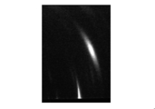
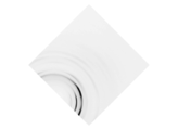
- FIG. 3 is a diagram showing an X-ray diffraction image of Example 1.
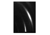
- FIG. 6 is a diagram showing an X-ray diffraction image of Example 2.
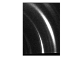
- FIG. 6 shows an X-ray diffraction image of Example 3.
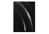
- FIG. 6 shows an X-ray diffraction image of Example 4.
- FIG. The figure which shows the X-ray-diffraction image of the comparative example 2.
- FIG. 6 shows an X-ray diffraction image of Example 5.
- FIG. 6 shows an X-ray diffraction image of Example 6.
- FIG. 10 shows an X-ray diffraction image of Example 8.
- FIG. 10 shows an X-ray diffraction image of Example 9.
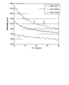
- FIG. 11 shows an X-ray diffraction image of Example 10. The figure which shows the scintillation counter measurement result in Example 9, the comparative example 5, and the measurement wavelength of 1.54 mm of the comparative example 6.
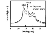
- FIG. FIG. 10 shows an X-ray diffraction profile of Example 11.
- a first aspect of the present invention is a resin composition containing nanofibers in a hydrophilic resin or a polyolefin resin, and is derived from a crystalline component of the resin when the resin composition is measured by X-ray diffraction.
- the X-ray diffraction image is characterized by having an intensity distribution in the circumferential direction.
- “when the resin composition is measured by X-ray diffraction, the X-ray diffraction image derived from the crystal component of the resin has an intensity distribution in the circumferential direction” means that the film is formed by forming the resin composition into a film.
- the degree of orientation ⁇ calculated by the following formula (I) is larger than 0.34 and satisfies the following formula (II). means.
- ⁇ represents the degree of orientation
- H represents the half width in the circumferential direction.
- the half width is the maximum value (peak value) of the diffraction intensity in the azimuth-diffraction intensity profile of (120) plane ((040) plane in isotactic polypropylene). The minimum width between the azimuth angles which is half of the angle is shown.
- H has a plurality of peaks in the azimuth angle range of 0 degrees or more and 180 degrees or less
- H is the sum of the half widths of all peaks.
- the orientation degree ⁇ is 1, it means complete orientation, and when it is 0, it means no orientation.
- the relationship between the degree of orientation ⁇ and the thickness of a film obtained by forming a resin composition preferably satisfies the following formula.
- ⁇ represents the degree of orientation
- X represents the film thickness (nm).
- Cellulose nanofibers are preferred as the nanofibers used in the present invention.
- the cellulose nanofiber include purified pulp obtained from conifers and broadleaf trees, cellulose obtained from cotton linters and cotton lint, cellulose obtained from seaweeds such as valonia and falcon, cellulose obtained from sea squirts, cellulose produced by bacteria, etc.
- Regenerated cellulose obtained by refining natural cellulose is preferably used.
- the average fiber diameter of the cellulose nanofiber is preferably 4 to 1000 nm. If it is smaller than 4 nm, it tends to be difficult to produce nanofibers. On the other hand, in the case of 1000 nm or less, the dispersibility of the resin becomes good and the gas barrier property tends to be improved.
- the analysis of the average fiber diameter is performed as follows. A dispersion of a fibrous filler having a solid content of 0.05 wt% to 0.1 wt% is prepared, and the dispersion is cast or spin-coated on a carbon film-coated grid to obtain a TEM (transmission electron microscope). Use a sample for observation. Moreover, when the fiber of a big fiber diameter is included, you may observe the SEM (scanning electron microscope) image of the surface cast or spin-coated on glass. Observation with an electron microscope image is performed at a magnification of 5000 times, 10000 times, or 50000 times depending on the size of the constituent fibers.
- a sample and observation conditions (magnification, etc.) are set so that at least 20 fibers intersect the axis.
- two random axes are drawn vertically and horizontally per image, and the fiber diameter of the fiber intersecting with the axis is visually read.
- the average fiber diameter (number average fiber diameter) is calculated from the fiber diameter data thus obtained.
- the method for obtaining the cellulose nanofiber is not particularly limited, and a known chemical treatment method or mechanical treatment method can be used.
- a medium stirring mill treatment device for example, a vibration mill treatment device, a high-pressure homogenizer treatment device, and an ultrahigh-pressure homogenizer
- the cellulose nanofiber uses natural cellulose as a raw material, uses an N-oxyl compound as an oxidation catalyst in water, oxidizes the natural cellulose by acting a co-oxidant, It is preferable that it is obtained through an oxidation reaction step for obtaining a reaction product fiber in which at least a part of the hydroxyl group is oxidized. Furthermore, after the oxidation reaction step, it is obtained through a purification step for obtaining a reactant fiber impregnated with water by removing impurities and a dispersion step for dispersing the reactant fiber impregnated with water in a solvent. (Details are disclosed in JP 2010-270315 A).
- the amount of aldehyde group and carboxyl group (mmol / g) of cellulose relative to the weight of cellulose fiber is evaluated by the following method.
- 60 ml of a 0.5 to 1 wt% slurry was prepared from a cellulose sample that had been precisely weighed in dry weight, adjusted to pH 2.5 with 0.1 M hydrochloric acid aqueous solution, and 0.05 M sodium hydroxide aqueous solution was then added dropwise. To measure the electrical conductivity. The measurement is continued until the pH is about 11.
- the amount of functional group 1 is determined from the amount (V) of sodium hydroxide consumed in the neutralization step of the weak acid whose electrical conductivity changes slowly.
- the functional group amount 1 indicates the amount of carboxyl groups.
- the cellulose sample is oxidized for another 48 hours at room temperature in a 2% sodium chlorite aqueous solution adjusted to pH 4 to 5 with acetic acid, and the functional group amount 2 is measured again by the above method.
- a hydrophilic resin or a polyolefin resin is used as the resin.
- a hydrophilic resin is not particularly limited, but is selected from the group consisting of polyalkylene glycol resins, polyvinyl alcohol, polyethylene oxide, polyethyleneimine, derivatives thereof and copolymers thereof.
- a resin is desirable.
- the hydrophilic resin is preferably the polyalkylene glycol resin.
- polyalkylene glycol resin polymethyl glycol, polyethylene glycol, polypropyl glycol, polybutene glycol, polypentene glycol, or the like can be used. Among these, at least one selected from the group consisting of polyethylene glycol and polypropylene glycol is preferable, and polyethylene glycol is more preferable.
- the polyolefin resin used in the present invention is not particularly limited.
- high density polyethylene HDPE
- low density polyethylene LDPE
- linear low density polyethylene LLDPE
- high molecular weight polyethylene HMW-PE
- UHMW-PE ultra high molecular weight polyethylene
- iPP isotactic polypropylene
- sPP syndiotactic polypropylene
- polybutene derivatives thereof and copolymers thereof.
- the weight fraction of cellulose nanofibers is 0.5% by weight or more and less than 50.0% by weight, further 0.5% by weight or more and 25.0% by weight or less, based on the total weight of the resin composition in the present invention. It is preferable to blend cellulose nanofibers so that When the weight fraction of the cellulose nanofiber is not less than the lower limit, the orientation of the resin is improved, and when it is not more than the upper limit, the crystallization of the resin tends to be improved.
- the resin composition of the present invention can be obtained by mixing each component by any method.
- the method of mixing resin and a fibrous filler (cellulose nanofiber) as it is is mentioned. If necessary, it may be heated and mixed.
- a resin composition having excellent fibrous filler dispersibility can be obtained by using a method in which a fibrous filler dispersion solution is obtained using a solvent, the dispersion solution and the resin are stirred and mixed to obtain a uniform dispersion, and then the solvent is removed. Is preferable.
- a uniform resin composition can be obtained by impregnating a resin into a sheet obtained by freeze-drying a fibrous filler dispersion obtained by dispersing in a solvent.
- the solvent to be used it is preferable to use a solvent capable of maintaining the dispersibility of the fibrous filler.
- the solvent include, but are not limited to, methyl alcohol, ethyl alcohol, isopropyl alcohol, ethylene glycol, propylene glycol, diethylene glycol, dioxane, acetone, methyl ethyl ketone, methyl cellosolve, tetrahydrofuran, pentaerythritol, dimethyl sulfoxide, dimethylformamide, N -Methyl-2-pyrrolidone and the like.
- water may be used as a solvent.
- the said solvent can also be used individually or in mixture of 2 or more types. It is also possible to gradually change the polarizability of the original dispersion medium to the polarity of the target dispersion medium and disperse the fibrous filler in a dispersion medium having a different polarity.
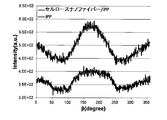
- the X-ray diffraction image derived from the crystal component of the resin has an intensity distribution in the circumferential direction ( ⁇ ), Appears in an arc, semicircle, or circle. This indicates that the resin of the resin composition of the present invention is oriented.
- the X-ray diffraction measurement is performed based on, for example, a transmission method or a grazing incidence X-ray diffraction method (which may be expressed as an oblique incidence X-ray diffraction method, a grazing incidence X-ray diffraction method, or a thin film X-ray diffraction method).
- the grazing incidence X-ray diffraction method is a method in which X-rays are incident on the sample surface at a low angle near the critical angle and diffraction from the sample is detected.
- the critical angle referred to here is an angle at which incident X-rays cause total reflection, specifically, an angle in the vicinity of 0 degrees.
- the measurement conditions are shown below.
- An X-ray diffractometer is used for the measurement.
- the X-ray diffractometer is not particularly limited, and examples thereof include NANO Viewer (Rigaku Corporation) and SPring-8 (High Intensity Optical Science Research Center) BL03XU and BL19B2.
- the measurement conditions with NANO Viewer are a wavelength of 1.54 mm and a camera length of 85.8 mm.
- PILATUS is used for the two-dimensional detector.
- the measurement conditions for SPring-8 are a wavelength of 1 mm, 1.24 mm, or 1.54 mm, an incident angle of 0.15 °, and a camera length of 63.6 mm.
- a scintillation counter is used for the zero-dimensional detector, and a flat panel display, imaging plate, IICCD, PILATUS, and PILATUS with a large-diameter solar slit are used for the two-dimensional detector.
- the X-ray diffraction image draws a semicircle or circle having no intensity distribution in the circumferential direction ( ⁇ ), it means that the crystal component of the resin is in a non-oriented state.
- the X-ray diffraction image draws a spot shape, an arc shape, a semicircle shape, or a circle shape having an intensity distribution in the circumferential direction ( ⁇ )
- the sample is placed so that the film surface is in the vertical direction, and X-rays are incident from the sample cross-sectional direction, if diffraction appears only in the vertical direction, the diffraction surface is positioned parallel to the sample surface. When diffraction appears only in the left-right direction, the diffraction surface is positioned perpendicular to the sample surface.
- the orientation degree ⁇ calculated using the above formula (I) is adopted.
- the degree of orientation ⁇ is preferably greater than 0.34 and satisfies the formula (II).
- the degree of orientation ⁇ is within the above range, the crystallization of the resin component in the resin composition can be improved, and the orientation of the crystal component of the resin can be improved, and the resin composition obtained thereby The gas bath barrier properties are significantly improved.
- the second aspect of the present invention is a thin film obtained by forming the resin composition of the first aspect, and the description of the same configuration as the first aspect will be omitted as appropriate.
- the thin film of this aspect has an intensity distribution in the circumferential direction ( ⁇ ) when the X-ray diffraction image derived from the crystal component of the resin has an X-ray diffraction measurement. Appears in the form of dots, arcs, semicircles, or circles.
- the degree of orientation ⁇ calculated by the formula (I) is preferably greater than 0.34 and satisfies the formula (II).
- the thickness of the thin film is preferably 300 nm or less, more preferably 20 to 300 nm. When the thickness is within the range, the orientation of the resin tends to be further improved.
- the film thickness can be measured by a micrometer or an ellipsometer, and specifically, measured using an n & k analyzer 1500 (n & k Technology, Inco.). A value having a fitting result of 99.5% or more is adopted as the measurement value, and the average value of the measurement values obtained at five different points is calculated as the film thickness.
- Examples of the method for obtaining a thin film from the resin composition of the first aspect include spin coating, casting, LB film generation, dipping method, and hot pressing method.
- the spin coat method is preferable from the viewpoints of film thickness control and film thickness uniformity.
- a thin film can be formed by spin coating the resin composition on a substrate such as a silicon wafer with a spin coater.
- the rotation speed and time of the spin coater are appropriately selected according to the solvent (dispersion medium) used.
- the solvent is aqueous (hydrophilic)
- it is preferable that the rotation speed is 300 to 800 rpm and the rotation time is about 5 to 20 minutes.
- the hydrophilic treatment of the substrate is preferably a surface oxidation treatment, and examples thereof include plasma irradiation, corona discharge, acid / alkali immersion, and radiation irradiation treatment.
- reaction product fiber impregnated with water having a solid content of 2% by weight was obtained.
- reaction product fiber dispersion was treated 20 times at a pressure of 20 MPa using a high pressure homogenizer (manufactured by Noro Sovia, 15MR-8TA type) to obtain a transparent cellulose nanofiber-dispersed aqueous solution.
- This dispersion was spin-coated on a hydrophilic silicon wafer substrate (spin coater, manufactured by Mikasa, product number 1H-360S), negatively stained with 2% uranyl acetate, and observed by TEM.
- the maximum fiber diameter was 10 nm and the number average fiber diameter was 6 nm. Further, it was shown from a wide-angle X-ray diffraction image of transparent film-like cellulose obtained by drying that it was composed of cellulose having a cellulose I-type crystal structure.
- Example 1 The cellulose nanofiber-dispersed aqueous solution having a solid content concentration of 0.2% obtained in Production Example 1 and polyethylene glycol (manufactured by Wako Pure Chemical Industries, Ltd., average molecular weight 500000) were mixed and stirred at room temperature for 30 minutes.
- the obtained mixed solution was spin-coated on a silicon wafer to form a film, heated in an oven at 100 ° C. for 30 minutes in order to relieve the stress due to spin coating, and cooled at room temperature in the air, thereby A thin film having a fiber content of 1 wt% and a thickness of 50 nm was obtained.
- thin film A represents the thin film obtained in this example
- thin film B represents a thin film different from thin film A only in that it does not contain cellulose nanofibers.
- Example 2 The cellulose nanofiber-dispersed aqueous solution having a solid content concentration of 0.2% obtained in Production Example 1 and polyethylene glycol (manufactured by Wako Pure Chemical Industries, Ltd., average molecular weight 500000) were mixed and stirred at room temperature for 30 minutes.
- the obtained mixed solution was spin-coated on a silicon wafer to form a film, heated in an oven at 100 ° C. for 30 minutes in order to relieve the stress due to spin coating, and cooled at room temperature in the air, thereby A thin film having a fiber content of 1 wt% and a thickness of 85 nm was obtained.
- the X-ray diffraction image of the polyethylene glycol crystal (120) plane observed by grazing incidence X-ray diffraction of the obtained thin film has an intensity distribution in the circumferential direction, and the degree of orientation is 0.74. II) was satisfied.
- the contribution calculated in the same manner as in Example 1 was 3%.
- Example 3 The cellulose nanofiber-dispersed aqueous solution having a solid content concentration of 0.2% obtained in Production Example 1 and polyethylene glycol (manufactured by Wako Pure Chemical Industries, Ltd., average molecular weight 500000) were mixed and stirred at room temperature for 30 minutes.
- the obtained mixed solution was spin-coated on a silicon wafer to form a film, heated in an oven at 100 ° C. for 30 minutes in order to relieve the stress due to spin coating, and cooled at room temperature in the air, thereby A thin film having a fiber content of 1 wt% and a thickness of 233 nm was obtained.
- the X-ray diffraction image of the polyethylene glycol crystal (120) plane observed by grazing incidence X-ray diffraction of the obtained thin film has an intensity distribution in the circumferential direction, and the degree of orientation is 0.63. II) was satisfied.
- the contribution calculated in the same manner as in Example 1 was 5%.
- Example 4 The cellulose nanofiber-dispersed aqueous solution having a solid content concentration of 0.2% obtained in Production Example 1 and polyethylene glycol (manufactured by Wako Pure Chemical Industries, Ltd., average molecular weight 500000) were mixed and stirred at room temperature for 30 minutes. The obtained mixed solution was spin-coated on a silicon wafer to form a film, heated in an oven at 100 ° C. for 30 minutes in order to relieve the stress due to spin coating, and cooled at room temperature in the air, thereby A thin film having a fiber content of 10 wt% and a thickness of 49 nm was obtained.
- Example 5 The cellulose nanofiber-dispersed aqueous solution having a solid content concentration of 0.2% obtained in Production Example 1 and polyethylene glycol (manufactured by Wako Pure Chemical Industries, Ltd., average molecular weight 500000) were mixed and stirred at room temperature for 30 minutes.
- the obtained mixed solution was spin-coated on a silicon wafer to form a film, heated in an oven at 100 ° C. for 30 minutes in order to relieve the stress due to spin coating, and cooled at room temperature in the air, thereby A thin film having a fiber content of 5 wt% and a thickness of 50 nm was obtained.
- Example 6 The cellulose nanofiber-dispersed aqueous solution having a solid content concentration of 0.2% obtained in Production Example 1 and polyethylene glycol (manufactured by Wako Pure Chemical Industries, Ltd., average molecular weight 500000) were mixed and stirred at room temperature for 30 minutes.
- the obtained mixed solution was spin-coated on a silicon wafer to form a film, heated in an oven at 100 ° C. for 30 minutes in order to relieve the stress due to spin coating, and cooled at room temperature in the air, thereby A thin film having a fiber content of 25 wt% and a thickness of 39 nm was obtained.
- Example 7 The cellulose nanofiber-dispersed aqueous solution having a solid content concentration of 0.2% obtained in Production Example 1 and polyethylene glycol (manufactured by Wako Pure Chemical Industries, Ltd., average molecular weight 500000) were mixed and stirred at room temperature for 30 minutes.
- the obtained mixed solution is poured into a petri dish that has been subjected to mold release treatment, moisture is evaporated in an oven at a temperature of 50 ° C., and further dried in a vacuum oven at 120 ° C., and the content of cellulose nanofibers is 25 wt% and the thickness is 43 ⁇ m. A good film.
- the X-ray diffraction image of the polyethylene glycol crystal (120) plane observed from the obtained film cross-sectional direction has an intensity distribution in the circumferential direction and an orientation degree of 0.933, which satisfies the formula (II). there were.
- Example 8 The cellulose nanofiber-dispersed aqueous solution having a solid content concentration of 0.2% obtained in Production Example 1 and polyethylene glycol (manufactured by Wako Pure Chemical Industries, Ltd., average molecular weight 500000) were mixed and stirred at room temperature for 30 minutes.
- the obtained mixed solution is poured into a petri dish that has been subjected to mold release treatment, water is evaporated in an oven at a temperature of 50 ° C., and further dried in a vacuum oven at 120 ° C., and the content of cellulose nanofiber is 10 wt% and the thickness is 78 ⁇ m. A good film.
- the X-ray diffraction image of the polyethylene glycol crystal (120) plane observed from the cross-sectional direction of the obtained film has an intensity distribution in the circumferential direction and an orientation degree of 0.932, which satisfies the above formula (II) Met.
- Example 9 The cellulose nanofiber-dispersed aqueous solution having a solid content concentration of 0.2% obtained in Production Example 1 and polyethylene glycol (manufactured by Wako Pure Chemical Industries, Ltd., average molecular weight 500000) were mixed and stirred at room temperature for 30 minutes.
- the obtained mixed solution is poured into a petri dish that has been subjected to mold release treatment, moisture is evaporated in an oven at a temperature of 50 ° C., and further dried in a vacuum oven at 120 ° C., and the content of cellulose nanofibers is 5 wt% and the thickness is 61 ⁇ m. A good film.
- the obtained X-ray diffraction image of the polyethylene glycol crystal (120) plane observed from the cross-sectional direction of the film has an intensity distribution in the circumferential direction and an orientation degree of 0.906, which satisfies the above formula (II) Met.
- Example 10 The cellulose nanofiber-dispersed aqueous solution having a solid content concentration of 0.2% obtained in Production Example 1 and polyethylene glycol (manufactured by Wako Pure Chemical Industries, Ltd., average molecular weight 500000) were mixed and stirred at room temperature for 30 minutes.
- the obtained mixed solution is poured into a petri dish that has been subjected to mold release treatment, moisture is evaporated in an oven at a temperature of 50 ° C., and further dried in a vacuum oven at 120 ° C., and the content of cellulose nanofibers is 2 wt% and the thickness is 160 ⁇ m. A good film.
- the obtained X-ray diffraction image of the polyethylene glycol crystal (120) plane observed from the cross-sectional direction of the film has an intensity distribution in the circumferential direction and an orientation degree of 0.906, which satisfies the above formula (II) Met.
- FIG. 5 shows the measurement results of the films obtained in Example 1, Example 5, Comparative Example 1 and Comparative Example 2 with a scintillation counter at a measurement wavelength of 1.54 mm.
- FIG. 14 shows the measurement results with a scintillation counter of the films obtained in Example 9, Comparative Example 5 and Comparative Example 6 at a measurement wavelength of 1.54 mm. According to these results, peaks derived from PEG crystals were not observed from 50 wt% or more of CSNF (cellulose nanofiber), indicating that polyethylene glycol was in an amorphous state.
- CSNF cellulose nanofiber
- Test Example 1 About the film obtained in Example 8, Example 9, and Comparative Example 7, in accordance with JIS K7126 B, using an oxygen permeability measuring device (OX-TRAN 2 / 21ML manufactured by MOCON), the temperature was 25 ° C., The oxygen transmission rate was measured under constant temperature and humidity conditions with a humidity of 65%. The average value of the measurement values obtained at 10 different points within the measurement part (diameter 2.5 cm) was calculated as the film thickness. A value calculated by the following formula was used as an evaluation value of gas barrier properties (see Table 3 below).
- the film obtained in Comparative Example 7 exceeded the detection limit (344 cc / m 2 / day) and was inferior in gas barrier properties. On the other hand, the films obtained in Examples 8 and 9 were remarkably excellent in gas barrier properties.
- Example 11 A xylene solution of isotactic polypropylene (J106G, manufactured by Prime Polymer Co., Ltd.) was dropped on the freeze-dried cellulose nanofiber sheet obtained in Production Example 2, and after defoaming and resin impregnation under reduced pressure, 130 ° C. The solvent was removed on a hot plate. The film obtained by the glass plate with the release PET film stretched inside was sandwiched, a weight was placed from above, and heated at 180 ° C. for 30 minutes to melt the isotactic polypropylene. Then, the cellulose nanofiber composite film was obtained by heating at 120 degreeC for 3 hours. The cellulose nanofiber content of the obtained film was 21.1 wt%, and the film thickness was 182 ⁇ m. Moreover, the X-ray diffraction image of the isotactic polypropylene crystal (040) plane observed from the cross-sectional direction of the obtained film has an intensity distribution in the circumferential direction, and the degree of orientation is 0.46. ).
- Example 11 From the results of Example 11 and Comparative Example 8, the degree of orientation of the isotactic polypropylene resin was observed to be improved by 27% by adding cellulose nanofibers, thereby increasing the mechanical strength and improving the gas barrier property. It was.
- a resin composition having improved mechanical strength and improved gas barrier properties is provided.
- the said resin composition can be used conveniently for an optical film and a packaging material.
Landscapes
- Chemical & Material Sciences (AREA)
- Chemical Kinetics & Catalysis (AREA)
- Medicinal Chemistry (AREA)
- Polymers & Plastics (AREA)
- Organic Chemistry (AREA)
- Health & Medical Sciences (AREA)
- Engineering & Computer Science (AREA)
- Materials Engineering (AREA)
- Manufacturing & Machinery (AREA)
- Nanotechnology (AREA)
- Biochemistry (AREA)
- Life Sciences & Earth Sciences (AREA)
- Physics & Mathematics (AREA)
- Composite Materials (AREA)
- Condensed Matter Physics & Semiconductors (AREA)
- General Physics & Mathematics (AREA)
- Crystallography & Structural Chemistry (AREA)
- Dispersion Chemistry (AREA)
- Compositions Of Macromolecular Compounds (AREA)
- Manufacture Of Macromolecular Shaped Articles (AREA)
- Paints Or Removers (AREA)
Abstract
親水性樹脂またはポリオレフィン樹脂中にナノファイバーを含有することを特徴とする樹脂組成物であって、前記ナノファイバーがセルロースナノファイバーであり、その平均繊維径は4~1000nmである。該樹脂組成物のX線回折像が強度分布を有し、これは樹脂結晶が配向していることを示している。
Description
本発明は親水性樹脂またはポリオレフィン樹脂と、ナノファイバーとを含む樹脂組成物、当該樹脂組成物からなる薄膜、およびその製造方法に関する。
本願は、日本国において、2011年12月19日に出願された特願2011-276568号、2012年3月29日に出願された特願2012-075520号、2012年2月10日に出願された特願2012-026811号、及び2012年3月30日に出願された特願2012-078683号に基づき優先権を主張し、その内容をここに援用する。
本願は、日本国において、2011年12月19日に出願された特願2011-276568号、2012年3月29日に出願された特願2012-075520号、2012年2月10日に出願された特願2012-026811号、及び2012年3月30日に出願された特願2012-078683号に基づき優先権を主張し、その内容をここに援用する。
一般的に樹脂の結晶化度が大きくなると共にガスバリア性も大きくなる。ガスは樹脂中の非晶部を通過するため、結晶化度が大きくなるとガスの通過距離が長くなるためである。さらに、樹脂結晶が配向した場合、無配向状態と比較してガスの通過距離が長くなり、それに伴いガスバリア性も大きくなる(非特許文献1)。
樹脂中にナノファイバーを充てんすることで力学強度を高められたという報告やナノファイバー自体の配向性について言及している報告は多数ある(特許文献1、2)。
しかしながら、樹脂にナノファイバーを充てんすることで樹脂結晶の配向を確認することはされていない。さらに、当該樹脂において、X線回折を用いて樹脂結晶の配向を調べられたことはない。
しかしながら、樹脂にナノファイバーを充てんすることで樹脂結晶の配向を確認することはされていない。さらに、当該樹脂において、X線回折を用いて樹脂結晶の配向を調べられたことはない。
特に樹脂が薄膜状である場合には、樹脂が自然に配向するとされているが、その程度は十分ではない。
「ガスバリア性・保香性包装材料の新展開」東レリサーチセンター編、出版、p.9(1999年刊)
樹脂にナノファイバーを充填し、樹脂結晶を配向させることで、力学強度を高め、さらにガスバリア性を改善した樹脂組成物を得ることを目的とする。
本発明は、以下のものを包含する。
(1)樹脂と、ナノファイバーとを含む樹脂組成物であって、
前記樹脂が、親水性樹脂またはポリオレフィン系であり、
前記樹脂組成物をX線回折測定した際に、前記樹脂の結晶成分に由来するX線回折像が、円周方向に強度分布を有することを特徴とする樹脂組成物。
(2) 前記樹脂組成物中の前記ナノファイバーの充てん率が0.5wt%以上50wt%未満である前記(1)項に記載の樹脂組成物。
(3) 前記樹脂組成物中の前記ナノファイバーの充てん率が0.5wt%以上25wt%以下である前記(2)項に記載の樹脂組成物。
(1)樹脂と、ナノファイバーとを含む樹脂組成物であって、
前記樹脂が、親水性樹脂またはポリオレフィン系であり、
前記樹脂組成物をX線回折測定した際に、前記樹脂の結晶成分に由来するX線回折像が、円周方向に強度分布を有することを特徴とする樹脂組成物。
(2) 前記樹脂組成物中の前記ナノファイバーの充てん率が0.5wt%以上50wt%未満である前記(1)項に記載の樹脂組成物。
(3) 前記樹脂組成物中の前記ナノファイバーの充てん率が0.5wt%以上25wt%以下である前記(2)項に記載の樹脂組成物。
(4) 前記ナノファイバーがセルロースナノファイバーである前記(1)ないし(3)項のいずれか1項に記載の樹脂組成物。
(5) 前記セルロースナノファイバーの平均繊維径が4~1000nmである前記(4)項記載の樹脂組成物。
(6) 前記セルロースナノファイバーがセルロース化学処理及び/又は機械的処理により平均繊維径を4~1000nmまで微細化した繊維である前記(5)項に記載の樹脂組成物。
(7) 前記セルロースナノファイバーの分子中に有する水酸基の少なくとも一部が酸化されている前記(4)ないし(6)項のいずれか1項に記載の樹脂組成物。
(8) 前記セルロースナノファイバーが、天然セルロースを、水溶媒中においてN-オキシル化合物を酸化触媒とし、共酸化剤を作用させることにより得られたものである前記(4)ないし(7)項のいずれか1項に記載の樹脂組成物。
(5) 前記セルロースナノファイバーの平均繊維径が4~1000nmである前記(4)項記載の樹脂組成物。
(6) 前記セルロースナノファイバーがセルロース化学処理及び/又は機械的処理により平均繊維径を4~1000nmまで微細化した繊維である前記(5)項に記載の樹脂組成物。
(7) 前記セルロースナノファイバーの分子中に有する水酸基の少なくとも一部が酸化されている前記(4)ないし(6)項のいずれか1項に記載の樹脂組成物。
(8) 前記セルロースナノファイバーが、天然セルロースを、水溶媒中においてN-オキシル化合物を酸化触媒とし、共酸化剤を作用させることにより得られたものである前記(4)ないし(7)項のいずれか1項に記載の樹脂組成物。
(9) 前記樹脂が前記親水性樹脂であり、前記親水性樹脂が、ポリアルキレングリコール樹脂、ポリビニルアルコール、ポリエチレンオキシド、ポリエチレンイミン、それらの誘導体およびそれらの共重合体からなる群より選択される少なくとも1種である前記(1)ないし(8)項のいずれか1項に記載の樹脂組成物。
(10) 前記親水性樹脂が前記ポリアルキレングリコール樹脂であり、前記ポリアルキレングリコール樹脂が、ポリエチレングリコール及びポリプロピレングリコールからなる群から選択される少なくとも一つである前記(9)項に記載の樹脂組成物。
(11) 前記樹脂が前記ポリオレフィン樹脂であり、前記ポリオレフィン樹脂が、高密度ポリエチレン、低密度ポリエチレン、線形低密度ポリエチレン、高分子量ポリエチレン、超高分子量ポリエチレン、アイソタクチックポリプロピレン、シンジオタクチックポリプロピレン、ポリブテン、および、それらの誘導体およびそれらの共重合体からなる群より選択されるポリオレフィン樹脂である前記(1)ないし(8)項のいずれか1項に記載の樹脂組成物。
(10) 前記親水性樹脂が前記ポリアルキレングリコール樹脂であり、前記ポリアルキレングリコール樹脂が、ポリエチレングリコール及びポリプロピレングリコールからなる群から選択される少なくとも一つである前記(9)項に記載の樹脂組成物。
(11) 前記樹脂が前記ポリオレフィン樹脂であり、前記ポリオレフィン樹脂が、高密度ポリエチレン、低密度ポリエチレン、線形低密度ポリエチレン、高分子量ポリエチレン、超高分子量ポリエチレン、アイソタクチックポリプロピレン、シンジオタクチックポリプロピレン、ポリブテン、および、それらの誘導体およびそれらの共重合体からなる群より選択されるポリオレフィン樹脂である前記(1)ないし(8)項のいずれか1項に記載の樹脂組成物。
(12) 前記(1)ないし(11)項のいずれか1項に記載の樹脂組成物からなる薄膜。
(13) 前記薄膜の膜厚が、300nm以下である前記(12)項に記載の薄膜。
(14) 前記(1)ないし(11)項のいずれか1項に記載の樹脂組成物をスピンコートすることによりフィルムを作製する工程を含む、前記(12)または(13)項に記載の薄膜の作製方法。
(13) 前記薄膜の膜厚が、300nm以下である前記(12)項に記載の薄膜。
(14) 前記(1)ないし(11)項のいずれか1項に記載の樹脂組成物をスピンコートすることによりフィルムを作製する工程を含む、前記(12)または(13)項に記載の薄膜の作製方法。
親水性樹脂またはポリオレフィン樹脂にナノファイバーを充填し、樹脂結晶を配向させることで、力学強度を高め、さらにガスバリア性を改善した樹脂組成物を得ることができる。
本発明の第一の態様は、親水性樹脂またはポリオレフィン樹脂中にナノファイバーを含有した樹脂組成物であって、前記樹脂組成物をX線回折測定した際に、前記樹脂の結晶成分に由来するX線回折像が、円周方向に強度分布を有することを特徴としている。ここで、「樹脂組成物をX線回折測定した際に、樹脂の結晶成分に由来するX線回折像が、円周方向に強度分布を有する」とは、樹脂組成物の膜化により、膜断面方向から観察すると樹脂の結晶成分が配向することを意味し、好ましくは、下記式(I)により算出される配向度πが0.34より大きく、かつ、下記式(II)を満たすことを意味する。

式(I)中、πは配向度、Hは円周方向での半価幅を示す。半価幅は、例えば、前記樹脂がポリアルキレングリコールの場合は(120)面(アイソタクチックポリプロピレンでは(040)面)の方位角-回析強度プロファイルにおける回折強度が、極大値(ピーク値)の半分となる方位角間の最小幅を示す。Hは、方位角0度以上180度以下の範囲でピークが複数存在する場合、全てのピークの半価幅を足したものとする。配向度πは1のときに完全配向、0のときに無配向状態を意味する。
前記配向度πは、樹脂組成物を成膜して得た膜の厚みとの関係が、下記式を満たすことが好ましい。
π>1.5958X-0.18 (II)
式(II)中、πは配向度を示し、Xは膜厚(nm)を示す。
本発明で用いるナノファイバーとして、セルロースナノファイバーが好ましい。当該セルロースナノファイバーとしては、針葉樹や広葉樹から得られる精製パルプ、コットンリンターやコットンリントより得られるセルロース、バロニアやシオグサなどの海草より得られるセルロース、ホヤより得られるセルロース、バクテリアの生産するセルロースなどの天然セルロースを微細化した再生セルロースが好適に使用される。
前記セルロースナノファイバーの平均繊維径は、4~1000nmであることが好ましい。4nmより小さい場合は、ナノファイバーの作製が困難となる傾向にある。一方、1000nm以下の場合は、樹脂の分散性が良好となり、ガスバリア性が向上する傾向にある。
前記平均繊維径の解析は次のようにして行う。固形分率で0.05重量%~0.1重量%の繊維状フィラーの分散体を調製し、該分散体を、カーボン膜被覆グリッド上にキャストまたはスピンコートしてTEM(透過型電子顕微鏡)観察用試料とする。また、大きな繊維径の繊維を含む場合には、ガラス上へキャストまたはスピンコートした表面のSEM(走査型電子顕微鏡)像を観察してもよい。構成する繊維の大きさに応じて5000倍、10000倍あるいは50000倍のいずれかの倍率で電子顕微鏡画像による観察を行う。此の際に、得られた画像内に縦横任意の画像幅の軸を想定した場合に少なくとも軸に対し、20本以上の繊維が軸と交差するような試料および観察条件(倍率等)とする。この条件を満足する観察画像に対し、1枚の画像当たり縦横2本ずつの無作為な軸を引き、軸に交錯する繊維の繊維径を目視で読み取っていく。こうして最低3枚の重なっていない表面部分の画像を電子顕微鏡で撮影し、各々2つの軸に交錯する繊維の繊維径の値を読み取る(したがって、最低20本×2×3=120本の繊維径の情報が得られる)。こうして得られた繊維径のデータにより平均繊維径(数平均繊維径)を算出する。
前記セルロースナノファイバーを得る方法としては特に限定されず公知の化学処理方法または機械的処理方法を使用することが出来、例えば媒体撹拌ミル処理装置、振動ミル処理装置、高圧ホモジナイザー処理装置、超高圧ホモジナイザー処置装置などの繊維をバラバラにする機能を有する装置を用いて繰り返し処理する方法、または、エレクトロスピニング法、スチームジェット法、APEX(登録商標)技術(Polymer Group.Inc)法などを採用することが出来る。
エネルギー効率などの観点から、特開2008-1728号公報に示す化学的に処理する方法で微細繊維を作製することが最も好ましい。具体的には、前記セルロースナノファイバーは、天然セルロースを原料とし、水中においてN-オキシル化合物を酸化触媒とし、共酸化剤を作用させることにより該天然セルロースを酸化して、セルロースナノファイバーの分子中に有する水酸基の少なくとも一部が酸化されている反応物繊維を得る酸化反応工程を経て得たものであることが好ましい。更には、前記酸化反応工程後に、不純物を除去して水を含浸させた反応物繊維を得る精製工程および水を含浸させた反応物繊維を溶媒に分散させる分散工程を経て得たものであることが好ましい(詳細は特開2010-270315)。
エネルギー効率などの観点から、特開2008-1728号公報に示す化学的に処理する方法で微細繊維を作製することが最も好ましい。具体的には、前記セルロースナノファイバーは、天然セルロースを原料とし、水中においてN-オキシル化合物を酸化触媒とし、共酸化剤を作用させることにより該天然セルロースを酸化して、セルロースナノファイバーの分子中に有する水酸基の少なくとも一部が酸化されている反応物繊維を得る酸化反応工程を経て得たものであることが好ましい。更には、前記酸化反応工程後に、不純物を除去して水を含浸させた反応物繊維を得る精製工程および水を含浸させた反応物繊維を溶媒に分散させる分散工程を経て得たものであることが好ましい(詳細は特開2010-270315)。
セルロース繊維の重量に対するセルロースのアルデヒド基およびカルボキシル基の量(mmol/g)は、以下の手法により評価する。
乾燥重量を精秤したセルロース試料から0.5~1重量%スラリーを60ml調製し、0.1Mの塩酸水溶液によってpHを約2.5とした後、0.05Mの水酸化ナトリウム水溶液を滴下して電気伝導度測定を行う。測定はpHが約11になるまで続ける。電気伝導度の変化が緩やかな弱酸の中和段階において消費された水酸化ナトリウム量(V)から、下式を用いて官能基量1を決定する。該官能基量1がカルボキシル基の量を示す。
官能基量(mmol/g)=V(ml)×0.05/セルロースの質量(g)
次に、セルロース試料を、酢酸でpHを4~5に調整した2%亜塩素酸ナトリウム水溶液中でさらに48時間常温で酸化し、上記手法によって再び官能基量2を測定する。この酸化によって追加された官能基量(=官能基量2-官能基量1)を算出し、アルデヒド基量とする。
次に樹脂について述べる。
本発明において樹脂は親水性樹脂又はポリオレフィン樹脂を用いる。
セルロースナノファイバーと混ぜて樹脂組成物を調製させる際に、セルロースナノファイバーと相溶性の高い溶媒を用いる観点から、前記樹脂として親水性樹脂を用いることが好ましい。
本発明に用いる親水性樹脂としては、特に限定するものではないが、ポリアルキレングリコール樹脂、ポリビニルアルコール、ポリエチレンオキシド、ポリエチレンイミン、それらの誘導体およびそれらの共重合体からなる群より選択される親水性樹脂であることが望ましい。
本発明において樹脂は親水性樹脂又はポリオレフィン樹脂を用いる。
セルロースナノファイバーと混ぜて樹脂組成物を調製させる際に、セルロースナノファイバーと相溶性の高い溶媒を用いる観点から、前記樹脂として親水性樹脂を用いることが好ましい。
本発明に用いる親水性樹脂としては、特に限定するものではないが、ポリアルキレングリコール樹脂、ポリビニルアルコール、ポリエチレンオキシド、ポリエチレンイミン、それらの誘導体およびそれらの共重合体からなる群より選択される親水性樹脂であることが望ましい。
前記親水性樹脂は、前記ポリアルキレングリコール樹脂であることが好ましい。当該ポリアルキレングリコール樹脂としては、ポリメチルグリコール、ポリエチレングリコール、ポリプロピルグリコール、ポリブテングリコール、ポリペンテングリコール等を用いることができる。これらの中でも、ポリエチレングリコール及びポリプロピレングリコールからなる群から選択される少なくとも一つであることが好ましく、ポリエチレングリコールであることがより好ましい。
本発明に用いるポリオレフィン樹脂としては、特に限定するものではないが、例えば、高密度ポリエチレン(HDPE)、低密度ポリエチレン(LDPE)、線形低密度ポリエチレン(LLDPE)、高分子量ポリエチレン(HMW-PE)、超高分子量ポリエチレン(UHMW-PE)、アイソタクチックポリプロピレン(iPP)、シンジオタクチックポリプロピレン(sPP)、ポリブテン、それらの誘導体およびそれらの共重合体からなる群より選択されるポリオレフィン樹脂であることが好ましい。これらの中でも、線形低密度ポリエチレン及びアイソタクチックポリプロピレンからなる群から選択される少なくとも一つを用いることがより好ましく、アイソタクチックポリプロピレンを用いることがより更に好ましい。
本発明における樹脂組成物においては、ナノファイバー量が多くなるほど樹脂の配向性が上がるが、樹脂の結晶化に劣る傾向にある。一方、ナノファイバー量が少ないと、配向効果に劣る傾向にある。
また、樹脂を薄膜化させることにより樹脂を配向させることが可能であるが、薄膜化だけでは十分な特性を得ることができない。
従って、本発明における樹脂組成物の全重量に対して、セルロースナノファイバーの重量分率が0.5重量%以上50.0重量%未満、さらには0.5重量%以上25.0重量%以下となるように、セルロースナノファイバーを配合することが好ましい。上記セルロースナノファイバーの重量分率が前記下限値以上である場合に、樹脂の配向性が向上し、上限値以下である場合に、樹脂の結晶化が向上する傾向にある。
また、樹脂を薄膜化させることにより樹脂を配向させることが可能であるが、薄膜化だけでは十分な特性を得ることができない。
従って、本発明における樹脂組成物の全重量に対して、セルロースナノファイバーの重量分率が0.5重量%以上50.0重量%未満、さらには0.5重量%以上25.0重量%以下となるように、セルロースナノファイバーを配合することが好ましい。上記セルロースナノファイバーの重量分率が前記下限値以上である場合に、樹脂の配向性が向上し、上限値以下である場合に、樹脂の結晶化が向上する傾向にある。
本発明の樹脂組成物は任意の方法により各成分を混合することにより得ることができる。例えば樹脂と繊維状フィラー(セルロースナノファイバー)をそのまま混合する方法が挙げられる。必要に応じて過熱して混合してよい。しかしながら溶剤を用いて繊維状フィラーの分散溶液にし、当該分散溶液と樹脂とを撹拌混合して均一分散液を得、後に脱溶媒する方法を用いると、繊維状フィラー分散性に優れた樹脂組成物を得ることができるため、好ましい。あるいは、溶剤に分散させて得た繊維状フィラーの分散溶液を凍結乾燥させたシートに樹脂を含浸することでも均一な樹脂組成物を得ることができる。
用いる溶剤としては繊維状フィラーの分散性を維持できる溶剤を用いることが好ましい。溶剤としては特に限定されないが例えば、メチルアルコール、エチルアルコール、イソプロピルアルコール、エチレングリコール、プロピレングリコール、ジエチレングリコール、ジオキサン、アセトン、メチルエチルケトン、メチルセルソルブ、テトラヒドロフラン、ペンタエリスリトール、ジメチルスルホキサイド、ジメチルホルムアミド、N-メチル-2-ピロリドンなどが挙げられる。前記樹脂として親水性樹脂を用いる場合は、溶剤として水を用いても良い。前記溶剤は、単独若しくは2種類以上を混合して用いることもできる。また、元の分散媒の分極率を目的の分散媒の極性へと徐々に変化させ、繊維状フィラーを異なる極性の分散媒に分散することも可能である。
本発明の樹脂組成物は、成膜後、X線回折測定した際に、前記樹脂の結晶成分に由来するX線回折像が、円周方向(Φ)に強度分布を有し、点状、円弧状、半円状、または円状に出現する。このことは、本発明の樹脂組成物の樹脂が配向していることを示している。
前記X線回折測定は、たとえば、透過法やすれすれ入射X線回折法(斜入射X線回折法、微小角入射X線回折法、薄膜X線回折法と表現する場合もある)に基づき実施される。すれすれ入射X線回折法とは、試料表面に対して臨界角付近の低角度でX線を入射し、試料からの回折を検出する手法である。ここで言う臨界角とは、入射X線が全反射を生じる角度であって、具体的には0度近傍の角度である。
以下に測定条件を示す。
測定にはX線回折装置が使用される。当該X線回折装置としては、特に限定するものではないが、例えば、NANO Viewer(株式会社リガク)やSPring-8(財団法人 高輝度光科学研究センター) BL03XUおよびBL19B2等が挙げられる。NANO Viewerでの測定条件は波長1.54Å、カメラ長85.8mmとする。二次元検出器にはPILATUSを使用する。SPring-8での測定条件は波長1Å、1.24Å、または1.54Å、入射角0.15°、カメラ長63.6mmとする。ゼロ次元検出器にはシンチレーションカウンターを使用し、二次元検出器にはフラットパネルディスプレイ、イメージングプレート、IICCD、PILATUS、大口径ソーラースリット付きのPILATUSを使用する。
測定にはX線回折装置が使用される。当該X線回折装置としては、特に限定するものではないが、例えば、NANO Viewer(株式会社リガク)やSPring-8(財団法人 高輝度光科学研究センター) BL03XUおよびBL19B2等が挙げられる。NANO Viewerでの測定条件は波長1.54Å、カメラ長85.8mmとする。二次元検出器にはPILATUSを使用する。SPring-8での測定条件は波長1Å、1.24Å、または1.54Å、入射角0.15°、カメラ長63.6mmとする。ゼロ次元検出器にはシンチレーションカウンターを使用し、二次元検出器にはフラットパネルディスプレイ、イメージングプレート、IICCD、PILATUS、大口径ソーラースリット付きのPILATUSを使用する。
X線回折像が円周方向(Φ)に強度分布のない半円状もしくは円状を描いている場合、前記樹脂の結晶成分が無配向状態であることを意味している。一方、X線回折像が円周方向(Φ)に強度分布のあるスポット状、円弧状、半円状、円状を描く場合、前記樹脂の結晶成分が配向していることを意味している(図18参照)。更に、試料を膜表面が上下方向になるように配置し、試料断面方向からX線を入射した場合、上下方向のみに回折が現れた場合、その回折面は試料表面と平行に位置しており、左右方向のみに回折が現れた場合、その回折面は試料表面と垂直に位置している。
配向評価として、前記式(I)を用いて算出される配向度πが採用される。前記配向度πは、0.34より大きく、かつ、前記式(II)を満たすものであることが好ましい。前記配向度πが前記範囲内であることにより、樹脂組成物中の樹脂成分の結晶化を向上し、かつ、当該樹脂の結晶成分の配向性を高めることができ、これにより得られる樹脂組成物のガスバスパリア性が顕著に向上する。
本発明の第二の態様は、前記第一の態様の樹脂組成物を成膜して得られた薄膜であり、第一の態様と同様の構成等について、その説明を適宜省略する。当該態様の薄膜は、第一の態様で記載の通り、X線回折測定した際には、前記樹脂の結晶成分に由来するX線回折像が、円周方向(Φ)に強度分布を有し、点状、円弧状、半円状、または円状に出現する。また、前記式(I)で算出される配向度πは、0.34より大きく、かつ、前記式(II)を満たすものであることが好ましい。
当該薄膜の膜厚は、好ましくは300nm以下、より好ましくは20~300nmである。当該膜厚範囲内である場合、樹脂の配向性がより高められる傾向にある。
前記膜厚は、マイクロメーターやエリプソメーターにより測定することができ、具体的には、n&k analyzer1500(n&k Tecknology,Inco.)を用いて測定される。測定値としてフィッティング結果が99.5%以上の値が採用され、異なる箇所5点で得られた測定値の平均値が膜厚として算出される。
前記膜厚は、マイクロメーターやエリプソメーターにより測定することができ、具体的には、n&k analyzer1500(n&k Tecknology,Inco.)を用いて測定される。測定値としてフィッティング結果が99.5%以上の値が採用され、異なる箇所5点で得られた測定値の平均値が膜厚として算出される。
前記第一の態様の樹脂組成物から薄膜を得る方法としては、例えばスピンコート、キャスト、LB膜生成、ディッピング法、熱プレス法等が挙げられる。
これらの中で、スピンコート法が、膜厚の制御、膜厚の均一性の観点から好ましい。当該スピンコート法としては、例えば、前記樹脂組成物を、シリコンウエハ等の基材に対してスピンコーターによりスピンコートすることにより薄膜を形成することができる。スピンコーターの回転数および時間は、使用する溶剤(分散媒)等に応じて適宜選択される。例えば、溶剤が水系(親水性)の場合には、回転数が300~800rpm、回転時間が5~20分間程度であることが好ましい。
前記スピンコートによる応力緩和のために、薄膜形成後、オーブンにて、樹脂の融点から10~50℃程度高い温度で30~60分間程度加熱することが好ましい。
これらの中で、スピンコート法が、膜厚の制御、膜厚の均一性の観点から好ましい。当該スピンコート法としては、例えば、前記樹脂組成物を、シリコンウエハ等の基材に対してスピンコーターによりスピンコートすることにより薄膜を形成することができる。スピンコーターの回転数および時間は、使用する溶剤(分散媒)等に応じて適宜選択される。例えば、溶剤が水系(親水性)の場合には、回転数が300~800rpm、回転時間が5~20分間程度であることが好ましい。
前記スピンコートによる応力緩和のために、薄膜形成後、オーブンにて、樹脂の融点から10~50℃程度高い温度で30~60分間程度加熱することが好ましい。
前記溶剤が水系の場合には、前記基材を親水性処理し、溶剤の展開を容易にすることが好ましい。前記基材の親水処理は、表面酸化処理が好ましく、例えば、プラズマ照射、コロナ放電、酸・アルカリ浸漬、放射線照射処理などが挙げられる。
本発明を実施例に基づいて詳細に説明するが、本発明の技術範囲はこれらの実施例に限定されるものではない。
(作製例1)
乾燥重量で2g相当分の未乾燥のパルプ(主に1000nmを超える繊維径の繊維から成る)、0.025gのTEMPO(2,2,6,6-テトラメチル-1-ピペリジン-N-オキシル)および0.25gの臭化ナトリウムを水150mlに分散させた後、13重量%次亜塩素酸ナトリウム水溶液を、1gのパルプに対して次亜塩素酸ナトリウムの量が2.5mmolとなるように次亜塩素酸ナトリウムを加えて反応を開始した。反応中は0.5Mの水酸化ナトリウム水溶液を滴下してpHを10.5に保った。pHに変化が見られなくなった時点で反応終了と見なし、0.5Mの塩酸水溶液でpH7に中和し反応物をガラスフィルターにてろ過した後、十分な量の水による水洗、ろ過を6回繰り返し、固形分量2重量%の水を含浸させた反応物繊維を得た。
乾燥重量で2g相当分の未乾燥のパルプ(主に1000nmを超える繊維径の繊維から成る)、0.025gのTEMPO(2,2,6,6-テトラメチル-1-ピペリジン-N-オキシル)および0.25gの臭化ナトリウムを水150mlに分散させた後、13重量%次亜塩素酸ナトリウム水溶液を、1gのパルプに対して次亜塩素酸ナトリウムの量が2.5mmolとなるように次亜塩素酸ナトリウムを加えて反応を開始した。反応中は0.5Mの水酸化ナトリウム水溶液を滴下してpHを10.5に保った。pHに変化が見られなくなった時点で反応終了と見なし、0.5Mの塩酸水溶液でpH7に中和し反応物をガラスフィルターにてろ過した後、十分な量の水による水洗、ろ過を6回繰り返し、固形分量2重量%の水を含浸させた反応物繊維を得た。
次に、該反応物繊維に水を加え0.2重量%とした。この該反応物繊維分散液を高圧ホモジナイザー(ノロ・ソビア製、15MR―8TA型)を用いて圧力20Mpaで20回処理し、透明なセルロースナノファイバー-分散水溶液を得た。
この分散体を親水処理済みのシリコンウエハ基材上でスピンコート後(スピンコート装置、ミカサ製、品番1H-360S)、2%ウラニルアセテートでネガティブ染色しTEM観察した。最大繊維径が10nmかつ、数平均繊維径が6nmであった。また、乾燥させて得られた透明な膜状のセルロースの広角X線回折像から、セルロースI型結晶構造を有するセルロースから成ることが示された。また同じ膜状セルロースのATR(Attenuated Total Reflectance)スペクトルのパターンからカルボニル基の存在が確認され、上述した方法により評価したセルロース中のアルデヒド基の量およびカルボキシル基の量はそれぞれ0.31mol/g、および1.7mmol/gであった。なお、前記分散体を親水処理済みのカーボン膜被覆グリッド上にキャストして成膜した場合においても、同一の結果が得られた。
(実施例1)
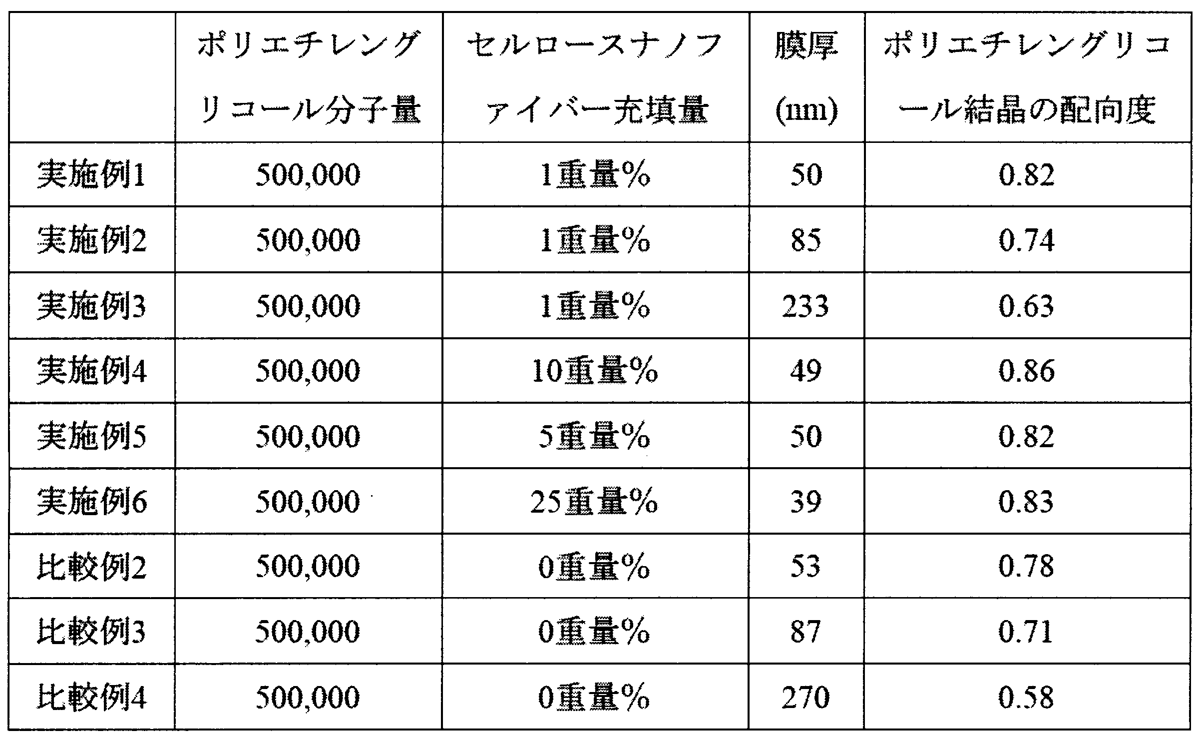
作製例1で得られた固形分濃度0.2%のセルロースナノファイバー分散水溶液とポリエチレングリコール(和光純薬工業製、平均分子量500000)とを混合し、室温で30分間撹拌した。得られた混合溶液をシリコンウエハ上にスピンコートすることにより成膜し、スピンコートによる応力を緩和するために100℃のオーブンにて30分加熱し、空気中室温で冷却することにより、セルロースナノファイバーの含有量が1wt%で厚み50nmの薄膜を得た。得られた薄膜をすれすれ入射X線回折法により観察したポリエチレングリコール結晶(120)面のX線回折像は、円周方向に強度分布を有し、配向度は0.82であり、前記式(II)を満たすものであった。
下記式に基づき算出したセルロースナノファイバーの樹脂配向への寄与率は4%であった。
作製例1で得られた固形分濃度0.2%のセルロースナノファイバー分散水溶液とポリエチレングリコール(和光純薬工業製、平均分子量500000)とを混合し、室温で30分間撹拌した。得られた混合溶液をシリコンウエハ上にスピンコートすることにより成膜し、スピンコートによる応力を緩和するために100℃のオーブンにて30分加熱し、空気中室温で冷却することにより、セルロースナノファイバーの含有量が1wt%で厚み50nmの薄膜を得た。得られた薄膜をすれすれ入射X線回折法により観察したポリエチレングリコール結晶(120)面のX線回折像は、円周方向に強度分布を有し、配向度は0.82であり、前記式(II)を満たすものであった。
下記式に基づき算出したセルロースナノファイバーの樹脂配向への寄与率は4%であった。

前記式中、薄膜Aは、本実施例にて得られた薄膜を示し、薄膜Bは、セルロースナノファイバーを含まない点でのみ薄膜Aと相違する薄膜を示す。
(実施例2)
作製例1で得られた固形分濃度0.2%のセルロースナノファイバー分散水溶液とポリエチレングリコール(和光純薬工業製、平均分子量500000)とを混合し、室温で30分間撹拌した。得られた混合溶液をシリコンウエハ上にスピンコートすることにより成膜し、スピンコートによる応力を緩和するために100℃のオーブンにて30分加熱し、空気中室温で冷却することにより、セルロースナノファイバーの含有量が1wt%で厚み85nmの薄膜を得た。得られた薄膜をすれすれ入射X線回折法により観察したポリエチレングリコール結晶(120)面のX線回折像は、円周方向に強度分布を有し、配向度は0.74であり、前記式(II)を満たすものであった。
実施例1と同様に算出した寄与率は3%であった。
作製例1で得られた固形分濃度0.2%のセルロースナノファイバー分散水溶液とポリエチレングリコール(和光純薬工業製、平均分子量500000)とを混合し、室温で30分間撹拌した。得られた混合溶液をシリコンウエハ上にスピンコートすることにより成膜し、スピンコートによる応力を緩和するために100℃のオーブンにて30分加熱し、空気中室温で冷却することにより、セルロースナノファイバーの含有量が1wt%で厚み85nmの薄膜を得た。得られた薄膜をすれすれ入射X線回折法により観察したポリエチレングリコール結晶(120)面のX線回折像は、円周方向に強度分布を有し、配向度は0.74であり、前記式(II)を満たすものであった。
実施例1と同様に算出した寄与率は3%であった。
(実施例3)
作製例1で得られた固形分濃度0.2%のセルロースナノファイバー分散水溶液とポリエチレングリコール(和光純薬工業製、平均分子量500000)とを混合し、室温で30分間撹拌した。得られた混合溶液をシリコンウエハ上にスピンコートすることにより成膜し、スピンコートによる応力を緩和するために100℃のオーブンにて30分加熱し、空気中室温で冷却することにより、セルロースナノファイバーの含有量が1wt%で厚み233nmの薄膜を得た。得られた薄膜をすれすれ入射X線回折法により観察したポリエチレングリコール結晶(120)面のX線回折像は、円周方向に強度分布を有し、配向度は0.63であり、前記式(II)を満たすものであった。
実施例1と同様に算出した寄与率は5%であった。
作製例1で得られた固形分濃度0.2%のセルロースナノファイバー分散水溶液とポリエチレングリコール(和光純薬工業製、平均分子量500000)とを混合し、室温で30分間撹拌した。得られた混合溶液をシリコンウエハ上にスピンコートすることにより成膜し、スピンコートによる応力を緩和するために100℃のオーブンにて30分加熱し、空気中室温で冷却することにより、セルロースナノファイバーの含有量が1wt%で厚み233nmの薄膜を得た。得られた薄膜をすれすれ入射X線回折法により観察したポリエチレングリコール結晶(120)面のX線回折像は、円周方向に強度分布を有し、配向度は0.63であり、前記式(II)を満たすものであった。
実施例1と同様に算出した寄与率は5%であった。
(実施例4)
作製例1で得られた固形分濃度0.2%のセルロースナノファイバー分散水溶液とポリエチレングリコール(和光純薬工業製、平均分子量500000)とを混合し、室温で30分間撹拌した。得られた混合溶液をシリコンウエハ上にスピンコートすることにより成膜し、スピンコートによる応力を緩和するために100℃のオーブンにて30分加熱し、空気中室温で冷却することにより、セルロースナノファイバーの含有量が10wt%で厚み49nmの薄膜を得た。得られた薄膜をすれすれ入射X線回折法により観察したポリエチレングリコール結晶(120)面のX線回折像は、円周方向に強度分布を有し、配向度は0.86であり、前記式(II)を満たすものであった。
実施例1と同様に算出した寄与率は9%であった。
作製例1で得られた固形分濃度0.2%のセルロースナノファイバー分散水溶液とポリエチレングリコール(和光純薬工業製、平均分子量500000)とを混合し、室温で30分間撹拌した。得られた混合溶液をシリコンウエハ上にスピンコートすることにより成膜し、スピンコートによる応力を緩和するために100℃のオーブンにて30分加熱し、空気中室温で冷却することにより、セルロースナノファイバーの含有量が10wt%で厚み49nmの薄膜を得た。得られた薄膜をすれすれ入射X線回折法により観察したポリエチレングリコール結晶(120)面のX線回折像は、円周方向に強度分布を有し、配向度は0.86であり、前記式(II)を満たすものであった。
実施例1と同様に算出した寄与率は9%であった。
(実施例5)
作製例1で得られた固形分濃度0.2%のセルロースナノファイバー分散水溶液とポリエチレングリコール(和光純薬工業製、平均分子量500000)とを混合し、室温で30分間撹拌した。得られた混合溶液をシリコンウエハ上にスピンコートすることにより成膜し、スピンコートによる応力を緩和するために100℃のオーブンにて30分加熱し、空気中室温で冷却することにより、セルロースナノファイバーの含有量が5wt%で厚み50nmの薄膜を得た。得られた薄膜をすれすれ入射X線回折法により観察したポリエチレングリコール結晶(120)面のX線回折像は、円周方向に強度分布を有し、配向度は0.82であり、前記式(II)を満たすものであった。
実施例1と同様に算出した寄与率は4%であった。
作製例1で得られた固形分濃度0.2%のセルロースナノファイバー分散水溶液とポリエチレングリコール(和光純薬工業製、平均分子量500000)とを混合し、室温で30分間撹拌した。得られた混合溶液をシリコンウエハ上にスピンコートすることにより成膜し、スピンコートによる応力を緩和するために100℃のオーブンにて30分加熱し、空気中室温で冷却することにより、セルロースナノファイバーの含有量が5wt%で厚み50nmの薄膜を得た。得られた薄膜をすれすれ入射X線回折法により観察したポリエチレングリコール結晶(120)面のX線回折像は、円周方向に強度分布を有し、配向度は0.82であり、前記式(II)を満たすものであった。
実施例1と同様に算出した寄与率は4%であった。
(実施例6)
作製例1で得られた固形分濃度0.2%のセルロースナノファイバー分散水溶液とポリエチレングリコール(和光純薬工業製、平均分子量500000)とを混合し、室温で30分間撹拌した。得られた混合溶液をシリコンウエハ上にスピンコートすることにより成膜し、スピンコートによる応力を緩和するために100℃のオーブンにて30分加熱し、空気中室温で冷却することにより、セルロースナノファイバーの含有量が25wt%で厚み39nmの薄膜を得た。得られた薄膜をすれすれ入射X線回折法により観察したポリエチレングリコール結晶(120)面のX線回折像は、円周方向に強度分布を有し、配向度は0.83であり、前記式(II)を満たすものであった。
実施例1と同様に算出した寄与率は1%であった。
作製例1で得られた固形分濃度0.2%のセルロースナノファイバー分散水溶液とポリエチレングリコール(和光純薬工業製、平均分子量500000)とを混合し、室温で30分間撹拌した。得られた混合溶液をシリコンウエハ上にスピンコートすることにより成膜し、スピンコートによる応力を緩和するために100℃のオーブンにて30分加熱し、空気中室温で冷却することにより、セルロースナノファイバーの含有量が25wt%で厚み39nmの薄膜を得た。得られた薄膜をすれすれ入射X線回折法により観察したポリエチレングリコール結晶(120)面のX線回折像は、円周方向に強度分布を有し、配向度は0.83であり、前記式(II)を満たすものであった。
実施例1と同様に算出した寄与率は1%であった。
(比較例1)
作製例1で得られた固形分濃度0.2%のセルロースナノファイバー分散水溶液とポリエチレングリコール(和光純薬工業製、平均分子量500000)とを混合し、室温で30分間撹拌した。得られた混合溶液をシリコンウエハ上にスピンコートすることにより成膜し、スピンコートによる応力を緩和するために100℃のオーブンにて30分加熱し、空気中室温で冷却することにより、セルロースナノファイバーの含有量が50wt%で厚み90nmの薄膜を得た。得られた薄膜のポリエチレングリコール結晶由来のX線回折像は観察されず、非晶状態であったため、配向度は算出できなかった。
作製例1で得られた固形分濃度0.2%のセルロースナノファイバー分散水溶液とポリエチレングリコール(和光純薬工業製、平均分子量500000)とを混合し、室温で30分間撹拌した。得られた混合溶液をシリコンウエハ上にスピンコートすることにより成膜し、スピンコートによる応力を緩和するために100℃のオーブンにて30分加熱し、空気中室温で冷却することにより、セルロースナノファイバーの含有量が50wt%で厚み90nmの薄膜を得た。得られた薄膜のポリエチレングリコール結晶由来のX線回折像は観察されず、非晶状態であったため、配向度は算出できなかった。
(比較例2)
ポリエチレングリコール(和光純薬工業製、平均分子量500000)水溶液をシリコンウエハ上にスピンコートすることにより成膜し、スピンコートによる応力を緩和するために100℃のオーブンにて30分加熱し、空気中室温で冷却することにより、厚み53nmの薄膜を得た。得られた薄膜をすれすれ入射X線回折法によりポリエチレングリコール結晶(120)面のX線回折像は観察され、配向度は0.78であったが、前記式(II)を満たさなかった。
ポリエチレングリコール(和光純薬工業製、平均分子量500000)水溶液をシリコンウエハ上にスピンコートすることにより成膜し、スピンコートによる応力を緩和するために100℃のオーブンにて30分加熱し、空気中室温で冷却することにより、厚み53nmの薄膜を得た。得られた薄膜をすれすれ入射X線回折法によりポリエチレングリコール結晶(120)面のX線回折像は観察され、配向度は0.78であったが、前記式(II)を満たさなかった。
(比較例3)
ポリエチレングリコール(和光純薬工業製、平均分子量500000)水溶液をシリコンウエハ上にスピンコートすることにより成膜し、スピンコートによる応力を緩和するために100℃のオーブンにて30分加熱し、空気中室温で冷却することにより、厚み87nmの薄膜を得た。得られた薄膜をすれすれ入射X線回折法によりポリエチレングリコール結晶(120)面のX線回折像は観察され、配向度は0.71であったが、前記式(II)を満たさなかった。
ポリエチレングリコール(和光純薬工業製、平均分子量500000)水溶液をシリコンウエハ上にスピンコートすることにより成膜し、スピンコートによる応力を緩和するために100℃のオーブンにて30分加熱し、空気中室温で冷却することにより、厚み87nmの薄膜を得た。得られた薄膜をすれすれ入射X線回折法によりポリエチレングリコール結晶(120)面のX線回折像は観察され、配向度は0.71であったが、前記式(II)を満たさなかった。
(比較例4)
ポリエチレングリコール(和光純薬工業製、平均分子量500000)水溶液をシリコンウエハ上にスピンコートすることにより成膜し、スピンコートによる応力を緩和するために100℃のオーブンにて30分加熱し、空気中室温で冷却することにより、厚み270nmの薄膜を得た。得られた薄膜をすれすれ入射X線回折法によりポリエチレングリコール結晶(120)面のX線回折像は観察され、配向度は0.58であったが、前記式(II)を満たさなかった。
ポリエチレングリコール(和光純薬工業製、平均分子量500000)水溶液をシリコンウエハ上にスピンコートすることにより成膜し、スピンコートによる応力を緩和するために100℃のオーブンにて30分加熱し、空気中室温で冷却することにより、厚み270nmの薄膜を得た。得られた薄膜をすれすれ入射X線回折法によりポリエチレングリコール結晶(120)面のX線回折像は観察され、配向度は0.58であったが、前記式(II)を満たさなかった。
(実施例7)
作製例1で得られた固形分濃度0.2%のセルロースナノファイバー分散水溶液とポリエチレングリコール(和光純薬工業製、平均分子量500000)とを混合し、室温で30分間撹拌した。得られた混合溶液を離型処理したシャーレに注ぎ、温度50℃のオーブンで水分を蒸発させ、さらに120℃の真空オーブン中で乾燥し、セルロースナノファイバーの含有量が25wt%で厚み43μmの透明なフィルムを得た。得られたフィルム断面方向から観察したポリエチレングリコール結晶(120)面のX線回折像は、円周方向に強度分布を有し、配向度は0.933であり、式(II)を満たすものであった。
作製例1で得られた固形分濃度0.2%のセルロースナノファイバー分散水溶液とポリエチレングリコール(和光純薬工業製、平均分子量500000)とを混合し、室温で30分間撹拌した。得られた混合溶液を離型処理したシャーレに注ぎ、温度50℃のオーブンで水分を蒸発させ、さらに120℃の真空オーブン中で乾燥し、セルロースナノファイバーの含有量が25wt%で厚み43μmの透明なフィルムを得た。得られたフィルム断面方向から観察したポリエチレングリコール結晶(120)面のX線回折像は、円周方向に強度分布を有し、配向度は0.933であり、式(II)を満たすものであった。
(実施例8)
作製例1で得られた固形分濃度0.2%のセルロースナノファイバー分散水溶液とポリエチレングリコール(和光純薬工業製、平均分子量500000)とを混合し、室温で30分間撹拌した。得られた混合溶液を離型処理したシャーレに注ぎ、温度50℃のオーブンで水分を蒸発させ、さらに120℃の真空オーブン中で乾燥し、セルロースナノファイバーの含有量が10wt%で厚み78μmの透明なフィルムを得た。得られたフィルム断面方向から観察したポリエチレングリコール結晶(120)面のX線回折像は、円周方向に強度分布を有し、配向度は0.932であり、前記式(II)を満たすものであった。
作製例1で得られた固形分濃度0.2%のセルロースナノファイバー分散水溶液とポリエチレングリコール(和光純薬工業製、平均分子量500000)とを混合し、室温で30分間撹拌した。得られた混合溶液を離型処理したシャーレに注ぎ、温度50℃のオーブンで水分を蒸発させ、さらに120℃の真空オーブン中で乾燥し、セルロースナノファイバーの含有量が10wt%で厚み78μmの透明なフィルムを得た。得られたフィルム断面方向から観察したポリエチレングリコール結晶(120)面のX線回折像は、円周方向に強度分布を有し、配向度は0.932であり、前記式(II)を満たすものであった。
(実施例9)
作製例1で得られた固形分濃度0.2%のセルロースナノファイバー分散水溶液とポリエチレングリコール(和光純薬工業製、平均分子量500000)とを混合し、室温で30分間撹拌した。得られた混合溶液を離型処理したシャーレに注ぎ、温度50℃のオーブンで水分を蒸発させ、さらに120℃の真空オーブン中で乾燥し、セルロースナノファイバーの含有量が5wt%で厚み61μmの透明なフィルムを得た。得られたフィルム断面方向から観察したポリエチレングリコール結晶(120)面のX線回折像は、円周方向に強度分布を有し、配向度は0.906であり、前記式(II)を満たすものであった。
作製例1で得られた固形分濃度0.2%のセルロースナノファイバー分散水溶液とポリエチレングリコール(和光純薬工業製、平均分子量500000)とを混合し、室温で30分間撹拌した。得られた混合溶液を離型処理したシャーレに注ぎ、温度50℃のオーブンで水分を蒸発させ、さらに120℃の真空オーブン中で乾燥し、セルロースナノファイバーの含有量が5wt%で厚み61μmの透明なフィルムを得た。得られたフィルム断面方向から観察したポリエチレングリコール結晶(120)面のX線回折像は、円周方向に強度分布を有し、配向度は0.906であり、前記式(II)を満たすものであった。
(実施例10)
作製例1で得られた固形分濃度0.2%のセルロースナノファイバー分散水溶液とポリエチレングリコール(和光純薬工業製、平均分子量500000)とを混合し、室温で30分間撹拌した。得られた混合溶液を離型処理したシャーレに注ぎ、温度50℃のオーブンで水分を蒸発させ、さらに120℃の真空オーブン中で乾燥し、セルロースナノファイバーの含有量が2wt%で厚み160μmの透明なフィルムを得た。得られたフィルム断面方向から観察したポリエチレングリコール結晶(120)面のX線回折像は、円周方向に強度分布を有し、配向度は0.906であり、前記式(II)を満たすものであった。
作製例1で得られた固形分濃度0.2%のセルロースナノファイバー分散水溶液とポリエチレングリコール(和光純薬工業製、平均分子量500000)とを混合し、室温で30分間撹拌した。得られた混合溶液を離型処理したシャーレに注ぎ、温度50℃のオーブンで水分を蒸発させ、さらに120℃の真空オーブン中で乾燥し、セルロースナノファイバーの含有量が2wt%で厚み160μmの透明なフィルムを得た。得られたフィルム断面方向から観察したポリエチレングリコール結晶(120)面のX線回折像は、円周方向に強度分布を有し、配向度は0.906であり、前記式(II)を満たすものであった。
(比較例5)
作製例1で得られた固形分濃度0.2%のセルロースナノファイバー分散水溶液とポリエチレングリコール(和光純薬工業製、平均分子量500,000)とを混合し、室温で30分間撹拌した。得られた混合溶液を離型処理したシャーレに注ぎ、温度50℃のオーブンで水分を蒸発させ、さらに120℃の真空オーブン中で乾燥し、セルロースナノファイバーの含有量が75wt%で厚み43μmの透明なフィルムを得た。得られたフィルムのポリエチレングリコール結晶由来のX線回折像は観察されず、非晶状態であったため、配向度は算出できなかった。
作製例1で得られた固形分濃度0.2%のセルロースナノファイバー分散水溶液とポリエチレングリコール(和光純薬工業製、平均分子量500,000)とを混合し、室温で30分間撹拌した。得られた混合溶液を離型処理したシャーレに注ぎ、温度50℃のオーブンで水分を蒸発させ、さらに120℃の真空オーブン中で乾燥し、セルロースナノファイバーの含有量が75wt%で厚み43μmの透明なフィルムを得た。得られたフィルムのポリエチレングリコール結晶由来のX線回折像は観察されず、非晶状態であったため、配向度は算出できなかった。
(比較例6)
作製例1で得られた固形分濃度0.2%のセルロースナノファイバー分散水溶液とポリエチレングリコール(和光純薬工業製、平均分子量500,000)とを混合し、室温で30分間撹拌した。得られた混合溶液を離型処理したシャーレに注ぎ、温度50℃のオーブンで水分を蒸発させ、さらに120℃の真空オーブン中で乾燥し、セルロースナノファイバーの含有量が50wt%で厚み43μmの透明なフィルムを得た。得られたフィルムのポリエチレングリコール結晶由来のX線回折像は観察されず、非晶状態であったため、配向度は算出できなかった。
作製例1で得られた固形分濃度0.2%のセルロースナノファイバー分散水溶液とポリエチレングリコール(和光純薬工業製、平均分子量500,000)とを混合し、室温で30分間撹拌した。得られた混合溶液を離型処理したシャーレに注ぎ、温度50℃のオーブンで水分を蒸発させ、さらに120℃の真空オーブン中で乾燥し、セルロースナノファイバーの含有量が50wt%で厚み43μmの透明なフィルムを得た。得られたフィルムのポリエチレングリコール結晶由来のX線回折像は観察されず、非晶状態であったため、配向度は算出できなかった。
(比較例7)
ポリエチレングリコール(和光純薬工業製、平均分子量500000)水溶液を離型処理したシャーレに注ぎ、温度50℃のオーブンで水分を蒸発させ、さらに120℃の真空オーブン中で乾燥し、厚み50μmの透明なフィルムを得た。得られたフィルム断面方向から観察したポリエチレングリコール結晶(120)面のX線回折像は、円周方向に強度分布を有さず、配向度は0であった。
ポリエチレングリコール(和光純薬工業製、平均分子量500000)水溶液を離型処理したシャーレに注ぎ、温度50℃のオーブンで水分を蒸発させ、さらに120℃の真空オーブン中で乾燥し、厚み50μmの透明なフィルムを得た。得られたフィルム断面方向から観察したポリエチレングリコール結晶(120)面のX線回折像は、円周方向に強度分布を有さず、配向度は0であった。
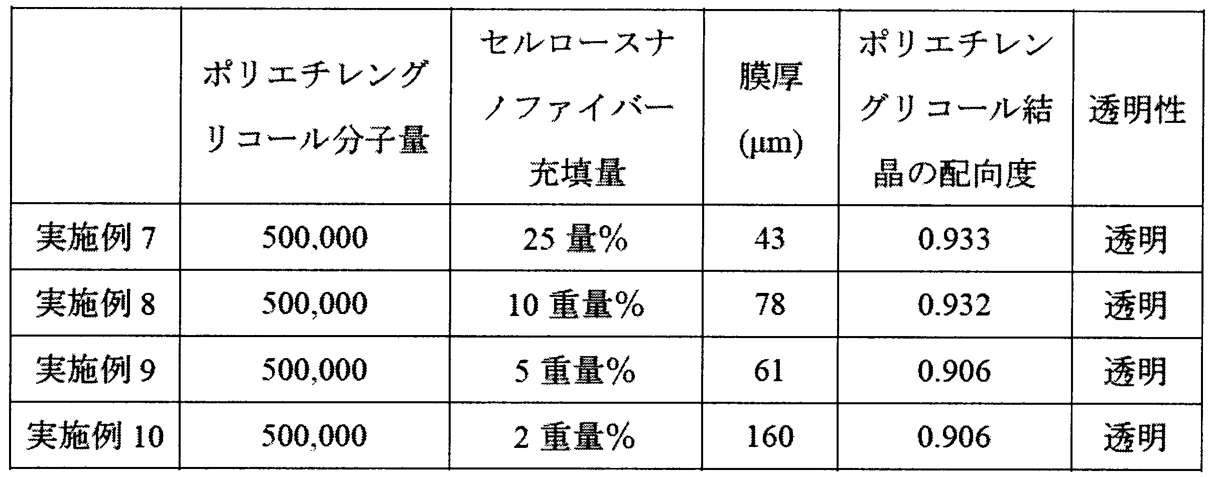
図5は、実施例1、実施例5、比較例1、および比較例2で得た膜の測定波長1.54Åにおけるシンチレーションカウンターでの測定結果を示す。同様に、図14は、実施例9、比較例5、および比較例6で得た膜の測定波長1.54Åにおけるシンチレーションカウンターでの測定結果を示す。これらの結果によれば、CSNF(セルロースナノファイバー)50wt%以上からはPEG結晶由来のピークが観察されず、ポリエチレングリコールが非晶状態であったことを示している。
(試験例1)
実施例8、実施例9、および比較例7で得たフィルムについて、JIS K7126 Bに準拠し、酸素透過率測定装置(MOCON社製 OXーTRAN 2/21ML)を使用して、温度25℃、湿度65%とした恒温恒湿条件下にて、酸素透過率を測定した。膜厚として測定部(直径2.5cm)以内の異なる箇所10点で得られた測定値の平均値を算出した。ガスバリア性の評価値として下記式により算出された値を用いた(下記表3参照)。
実施例8、実施例9、および比較例7で得たフィルムについて、JIS K7126 Bに準拠し、酸素透過率測定装置(MOCON社製 OXーTRAN 2/21ML)を使用して、温度25℃、湿度65%とした恒温恒湿条件下にて、酸素透過率を測定した。膜厚として測定部(直径2.5cm)以内の異なる箇所10点で得られた測定値の平均値を算出した。ガスバリア性の評価値として下記式により算出された値を用いた(下記表3参照)。


比較例7で得たフィルムは、検出限界(344cc/m2/day)超であり、ガスバリア性に劣るものであった。一方、実施例8および9で得たフィルムは、顕著にガスバリア性に優れたものであった。
(作製例2)
作製例1と同様にして得たセルロースナノファイバー分散水溶液を乾燥させて透明なセルロースナノファイバーシートを得た。このセルロースナノファイバーシートに水を加え10分静置することで、セルロースナノファイバーシートを膨潤させた。余分な水を除去し、50vol%エタノール水溶液を加えて10分静置した。同様の操作を70、80、90、100vol%エタノール水溶液を用いて行った。余分な100vol%エタノールを除去し、ブタノールを加えて15分静置する操作を4回繰り返すことでエタノールからブタノールに置換した。少しブタノールが容器に残る程度まで余分なブタノールを除去し、冷凍庫で2時間静置した。その後、凍結乾燥機(東京理化器械株式会社製 FDU-1200)にて凍結乾燥セルロースナノファイバーシートを得た。
作製例1と同様にして得たセルロースナノファイバー分散水溶液を乾燥させて透明なセルロースナノファイバーシートを得た。このセルロースナノファイバーシートに水を加え10分静置することで、セルロースナノファイバーシートを膨潤させた。余分な水を除去し、50vol%エタノール水溶液を加えて10分静置した。同様の操作を70、80、90、100vol%エタノール水溶液を用いて行った。余分な100vol%エタノールを除去し、ブタノールを加えて15分静置する操作を4回繰り返すことでエタノールからブタノールに置換した。少しブタノールが容器に残る程度まで余分なブタノールを除去し、冷凍庫で2時間静置した。その後、凍結乾燥機(東京理化器械株式会社製 FDU-1200)にて凍結乾燥セルロースナノファイバーシートを得た。
(実施例11)
作製例2で得られたセルロースナノファイバー凍結乾燥シートにアイソタクチックポリプロピレン(株式会社プライムポリマー製 J106G)のキシレン溶液を滴下し、減圧下にて脱泡および樹脂の含浸を行った後、130℃のホットプレート上で溶剤を除去した。離型PETフィルムを内側に張ったガラス板で得られたフィルムを挟み、上から重しを載せて、180℃で30分加熱することで、アイソタクチックポリプロピレンを融解させた。その後、120℃で3時間加熱することによりセルロースナノファイバー複合フィルムを得た。得られたフィルムのセルロースナノファイバーの含有量は21.1wt%、フィルムの厚みは182μmであった。また、得られたフィルムの断面方向から観察したアイソタクチックポリプロピレン結晶(040)面のX線回折像は円周方向に強度分布を有し、配向度は0.46であり、前記式(II)を満たすものであった。
作製例2で得られたセルロースナノファイバー凍結乾燥シートにアイソタクチックポリプロピレン(株式会社プライムポリマー製 J106G)のキシレン溶液を滴下し、減圧下にて脱泡および樹脂の含浸を行った後、130℃のホットプレート上で溶剤を除去した。離型PETフィルムを内側に張ったガラス板で得られたフィルムを挟み、上から重しを載せて、180℃で30分加熱することで、アイソタクチックポリプロピレンを融解させた。その後、120℃で3時間加熱することによりセルロースナノファイバー複合フィルムを得た。得られたフィルムのセルロースナノファイバーの含有量は21.1wt%、フィルムの厚みは182μmであった。また、得られたフィルムの断面方向から観察したアイソタクチックポリプロピレン結晶(040)面のX線回折像は円周方向に強度分布を有し、配向度は0.46であり、前記式(II)を満たすものであった。
(比較例8)
アイソタクチックポリプロピレン(株式会社プライムポリマー製 J106G)のキシレン溶液をガラスシャーレ上に入れ、130℃のホットプレート上で溶剤を除去した。離型PETフィルムを内側に張ったガラス板とスペーサーの間に得られたフィルムを置き、上から重しを載せて、180℃で30分加熱することで、アイソタクチックポリプロピレンを融解させた。その後、120℃で3時間加熱することによりアイソタクチックポリプロピレンフィルムを得た。得られたフィルムの厚みは153μmであった。また、得られたフィルムの断面方向からアイソタクチックポリプロピレン結晶(040)面のX線回折像が得られたが、樹脂の配向度は0.34であった。
アイソタクチックポリプロピレン(株式会社プライムポリマー製 J106G)のキシレン溶液をガラスシャーレ上に入れ、130℃のホットプレート上で溶剤を除去した。離型PETフィルムを内側に張ったガラス板とスペーサーの間に得られたフィルムを置き、上から重しを載せて、180℃で30分加熱することで、アイソタクチックポリプロピレンを融解させた。その後、120℃で3時間加熱することによりアイソタクチックポリプロピレンフィルムを得た。得られたフィルムの厚みは153μmであった。また、得られたフィルムの断面方向からアイソタクチックポリプロピレン結晶(040)面のX線回折像が得られたが、樹脂の配向度は0.34であった。
実施例11と比較例8の結果より、アイソタクチックポリプロピレン樹脂の配向度は、セルロースナノファイバーを加えることによって、27%の向上が観察され、これにより、力学強度が増し、ガスバリア性が向上された。
親水性樹脂またはポリオレフィン樹脂にナノファイバーを充填し、樹脂結晶を配向させることで、力学強度を高め、さらにガスバリア性を改善した樹脂組成物が提供される。当該樹脂組成物は、光学フィルム、包装材に好適に使用することができる。
Claims (14)
- 樹脂と、ナノファイバーとを含む樹脂組成物であって、
前記樹脂が、親水性樹脂またはポリオレフィン系であり、
前記樹脂組成物をX線回折測定した際に、前記樹脂の結晶成分に由来するX線回折像が、円周方向に強度分布を有することを特徴とする樹脂組成物。 - 前記樹脂組成物中の前記ナノファイバーの充てん率が0.5wt%以上50wt%未満である請求項1に記載の樹脂組成物。
- 前記樹脂組成物中の前記ナノファイバーの充てん率が0.5wt%以上25wt%以下である請求項2に記載の樹脂組成物。
- 前記ナノファイバーがセルロースナノファイバーである請求項1ないし3のいずれか1項に記載の樹脂組成物。
- 前記セルロースナノファイバーの平均繊維径が4~1000nmである請求項4記載の樹脂組成物。
- 前記セルロースナノファイバーがセルロース化学処理及び/又は機械的処理により平均繊維径を4~1000nmまで微細化した繊維である請求項5に記載の樹脂組成物。
- 前記セルロースナノファイバーの分子中に有する水酸基の少なくとも一部が酸化されている請求項4ないし6のいずれか1項に記載の樹脂組成物。
- 前記セルロースナノファイバーが、天然セルロースを、水溶媒中においてN-オキシル化合物を酸化触媒とし、共酸化剤を作用させることにより得られたものである請求項4ないし7のいずれか1項に記載の樹脂組成物。
- 前記樹脂が前記親水性樹脂であり、前記親水性樹脂が、ポリアルキレングリコール樹脂、ポリビニルアルコール、ポリエチレンオキシド、ポリエチレンイミン、それらの誘導体およびそれらの共重合体からなる群より選択される少なくとも1種である請求項1ないし8のいずれか1項に記載の樹脂組成物。
- 前記親水性樹脂が前記ポリアルキレングリコール樹脂であり、前記ポリアルキレングリコール樹脂が、ポリエチレングリコール及びポリプロピレングリコールからなる群から選択される少なくとも一つである請求項9に記載の樹脂組成物。
- 前記樹脂が前記ポリオレフィン樹脂であり、前記ポリオレフィン樹脂が、高密度ポリエチレン、低密度ポリエチレン、線形低密度ポリエチレン、高分子量ポリエチレン、超高分子量ポリエチレン、アイソタクチックポリプロピレン、シンジオタクチックポリプロピレン、ポリブテン、および、それらの誘導体およびそれらの共重合体からなる群より選択されるポリオレフィン樹脂である請求項1ないし8のいずれか1項に記載の樹脂組成物。
- 請求項1ないし11のいずれか1項に記載の樹脂組成物からなる薄膜。
- 前記薄膜の膜厚が、300nm以下である請求項12記載の薄膜。
- 請求項1ないし11いずれか1項に記載の樹脂組成物をスピンコートすることによりフィルムを作製する工程を含む、請求項12または13に記載の薄膜の作製方法。
Priority Applications (1)
| Application Number | Priority Date | Filing Date | Title |
|---|---|---|---|
| US14/366,065 US20140315009A1 (en) | 2011-12-19 | 2012-12-17 | Resin composition and method for producing same |
Applications Claiming Priority (8)
| Application Number | Priority Date | Filing Date | Title |
|---|---|---|---|
| JP2011276568 | 2011-12-19 | ||
| JP2011-276568 | 2011-12-19 | ||
| JP2012-026811 | 2012-02-10 | ||
| JP2012026811 | 2012-02-10 | ||
| JP2012-075520 | 2012-03-29 | ||
| JP2012075520 | 2012-03-29 | ||
| JP2012-078683 | 2012-03-30 | ||
| JP2012078683 | 2012-03-30 |
Publications (1)
| Publication Number | Publication Date |
|---|---|
| WO2013094563A1 true WO2013094563A1 (ja) | 2013-06-27 |
Family
ID=48668453
Family Applications (1)
| Application Number | Title | Priority Date | Filing Date |
|---|---|---|---|
| PCT/JP2012/082676 Ceased WO2013094563A1 (ja) | 2011-12-19 | 2012-12-17 | 樹脂組成物およびその製造方法 |
Country Status (3)
| Country | Link |
|---|---|
| US (1) | US20140315009A1 (ja) |
| JP (1) | JP2013227487A (ja) |
| WO (1) | WO2013094563A1 (ja) |
Cited By (3)
| Publication number | Priority date | Publication date | Assignee | Title |
|---|---|---|---|---|
| JP2017082387A (ja) * | 2013-06-03 | 2017-05-18 | 王子ホールディングス株式会社 | 微細繊維含有シートの製造方法 |
| CN107075189A (zh) * | 2014-10-20 | 2017-08-18 | 出光狮王塑料株式会社 | 聚烯烃树脂组成物 |
| JPWO2020196799A1 (ja) * | 2019-03-27 | 2020-10-01 |
Families Citing this family (4)
| Publication number | Priority date | Publication date | Assignee | Title |
|---|---|---|---|---|
| JP6570103B2 (ja) * | 2014-11-13 | 2019-09-04 | 中越パルプ工業株式会社 | 複合樹脂組成物及び複合樹脂組成物の製造方法。 |
| JP6226096B1 (ja) * | 2017-02-27 | 2017-11-08 | スターライト工業株式会社 | ガスバリア層形成用樹脂組成物 |
| JP7016235B2 (ja) * | 2017-10-12 | 2022-02-04 | スターライト工業株式会社 | ガスバリア層形成用樹脂組成物 |
| JP7087361B2 (ja) * | 2017-11-30 | 2022-06-21 | 凸版印刷株式会社 | 樹脂成形体及び樹脂成形体形成用組成物からなるコーティング剤 |
Citations (8)
| Publication number | Priority date | Publication date | Assignee | Title |
|---|---|---|---|---|
| JP2008001728A (ja) * | 2006-06-20 | 2008-01-10 | Asahi Kasei Corp | 微細セルロース繊維 |
| JP2009029927A (ja) * | 2007-07-26 | 2009-02-12 | Toyota Boshoku Corp | 熱可塑性樹脂組成物の製造方法及び成形体の製造方法 |
| JP2010242063A (ja) * | 2009-03-17 | 2010-10-28 | Kuraray Co Ltd | セルロースナノファイバー複合ポリビニルアルコール系重合体組成物 |
| JP2010270315A (ja) * | 2009-04-24 | 2010-12-02 | Sumitomo Bakelite Co Ltd | 複合体組成物 |
| JP2011105799A (ja) * | 2009-11-13 | 2011-06-02 | Konica Minolta Holdings Inc | 繊維複合材料、光学フィルム、光学フィルムの製造方法及びそれを用いた偏光板、液晶表示装置 |
| JP2011148914A (ja) * | 2010-01-22 | 2011-08-04 | Konica Minolta Holdings Inc | 繊維複合材料、光学フィルム、光学フィルムの製造方法、それを用いた偏光板および液晶表示装置 |
| JP2011184816A (ja) * | 2010-03-05 | 2011-09-22 | Olympus Corp | セルロースナノファイバーとその製造方法、複合樹脂組成物、成形体 |
| JP2012201767A (ja) * | 2011-03-24 | 2012-10-22 | Nissan Motor Co Ltd | 樹脂組成物 |
Family Cites Families (12)
| Publication number | Priority date | Publication date | Assignee | Title |
|---|---|---|---|---|
| JPH09278532A (ja) * | 1996-04-09 | 1997-10-28 | Showa Denko Kk | セラミックス生成剤およびセラミックスの製造方法 |
| JP2008266606A (ja) * | 2007-03-26 | 2008-11-06 | Techno Polymer Co Ltd | 耐アルコール性成形材料及び成形品 |
| JP4845129B2 (ja) * | 2007-03-28 | 2011-12-28 | 国立大学法人京都大学 | フレキシブル基板およびその製造方法 |
| WO2009025900A2 (en) * | 2007-05-26 | 2009-02-26 | Stonybrook Water Purification | High flux fluid separation membranes comprising a cellulose or cellulose derivative layer |
| US20100018641A1 (en) * | 2007-06-08 | 2010-01-28 | Kimberly-Clark Worldwide, Inc. | Methods of Applying Skin Wellness Agents to a Nonwoven Web Through Electrospinning Nanofibers |
| WO2009039438A2 (en) * | 2007-09-21 | 2009-03-26 | Boston Scientific Scimed, Inc. | Medical devices having nanofiber-textured surfaces |
| JP2010116477A (ja) * | 2008-11-13 | 2010-05-27 | Sumitomo Bakelite Co Ltd | 複合体組成物 |
| JP5295943B2 (ja) * | 2008-12-26 | 2013-09-18 | 花王株式会社 | ナノファイバシート |
| EP2371892A4 (en) * | 2008-12-26 | 2013-07-31 | Kao Corp | GAS BARRIER MATERIAL, GAS BARRIER MOLDING ITEM AND METHOD FOR PRODUCING THE GAS BARRIER MOLDING ARTICLE |
| US9371616B2 (en) * | 2009-01-05 | 2016-06-21 | Konica Minolta Holdings, Inc. | Laminate and production method thereof |
| JP2011068709A (ja) * | 2009-09-24 | 2011-04-07 | Konica Minolta Opto Inc | 光学フィルム、それを用いた透明ガスバリアフィルム、および光学フィルムの製造方法 |
| WO2011040547A1 (ja) * | 2009-09-30 | 2011-04-07 | 日本製紙株式会社 | 紙製バリア材料 |
-
2012
- 2012-12-17 WO PCT/JP2012/082676 patent/WO2013094563A1/ja not_active Ceased
- 2012-12-17 US US14/366,065 patent/US20140315009A1/en not_active Abandoned
- 2012-12-18 JP JP2012276239A patent/JP2013227487A/ja active Pending
Patent Citations (8)
| Publication number | Priority date | Publication date | Assignee | Title |
|---|---|---|---|---|
| JP2008001728A (ja) * | 2006-06-20 | 2008-01-10 | Asahi Kasei Corp | 微細セルロース繊維 |
| JP2009029927A (ja) * | 2007-07-26 | 2009-02-12 | Toyota Boshoku Corp | 熱可塑性樹脂組成物の製造方法及び成形体の製造方法 |
| JP2010242063A (ja) * | 2009-03-17 | 2010-10-28 | Kuraray Co Ltd | セルロースナノファイバー複合ポリビニルアルコール系重合体組成物 |
| JP2010270315A (ja) * | 2009-04-24 | 2010-12-02 | Sumitomo Bakelite Co Ltd | 複合体組成物 |
| JP2011105799A (ja) * | 2009-11-13 | 2011-06-02 | Konica Minolta Holdings Inc | 繊維複合材料、光学フィルム、光学フィルムの製造方法及びそれを用いた偏光板、液晶表示装置 |
| JP2011148914A (ja) * | 2010-01-22 | 2011-08-04 | Konica Minolta Holdings Inc | 繊維複合材料、光学フィルム、光学フィルムの製造方法、それを用いた偏光板および液晶表示装置 |
| JP2011184816A (ja) * | 2010-03-05 | 2011-09-22 | Olympus Corp | セルロースナノファイバーとその製造方法、複合樹脂組成物、成形体 |
| JP2012201767A (ja) * | 2011-03-24 | 2012-10-22 | Nissan Motor Co Ltd | 樹脂組成物 |
Cited By (10)
| Publication number | Priority date | Publication date | Assignee | Title |
|---|---|---|---|---|
| JP2017082387A (ja) * | 2013-06-03 | 2017-05-18 | 王子ホールディングス株式会社 | 微細繊維含有シートの製造方法 |
| US10697118B2 (en) | 2013-06-03 | 2020-06-30 | Oji Holdings Corporation | Method for producing sheet containing fine fibers |
| US11542659B2 (en) | 2013-06-03 | 2023-01-03 | Oji Holdings Corporation | Method for producing sheet containing fine fibers |
| CN107075189A (zh) * | 2014-10-20 | 2017-08-18 | 出光狮王塑料株式会社 | 聚烯烃树脂组成物 |
| US20170313858A1 (en) * | 2014-10-20 | 2017-11-02 | Chuetsu Pulp & Paper Co., Ltd | Polyolefin resin composition |
| CN107075189B (zh) * | 2014-10-20 | 2019-12-17 | 出光狮王塑料株式会社 | 聚烯烃树脂组成物 |
| JPWO2020196799A1 (ja) * | 2019-03-27 | 2020-10-01 | ||
| WO2020196799A1 (ja) * | 2019-03-27 | 2020-10-01 | 古河電気工業株式会社 | セルロース繊維強化ポリプロピレン樹脂成形体及びその製造方法 |
| JP7470674B2 (ja) | 2019-03-27 | 2024-04-18 | 古河電気工業株式会社 | セルロース繊維強化ポリプロピレン樹脂成形体及びその製造方法 |
| US12195614B2 (en) | 2019-03-27 | 2025-01-14 | Furukawa Electric Co., Ltd. | Cellulose fiber-reinforced polypropylene resin formed body and method for producing the same |
Also Published As
| Publication number | Publication date |
|---|---|
| US20140315009A1 (en) | 2014-10-23 |
| JP2013227487A (ja) | 2013-11-07 |
Similar Documents
| Publication | Publication Date | Title |
|---|---|---|
| JP2013227487A (ja) | 樹脂組成物およびその製造方法 | |
| Kwon et al. | Cellulose nanocrystal-coated TEMPO-oxidized cellulose nanofiber films for high performance all-cellulose nanocomposites | |
| Chowdhury et al. | Cellulose nanocrystal (CNC) coatings with controlled anisotropy as high-performance gas barrier films | |
| Thiangtham et al. | Fabrication of biocomposite membrane with microcrystalline cellulose (MCC) extracted from sugarcane bagasse by phase inversion method | |
| Yu et al. | Contribution of hemicellulose to cellulose nanofiber-based nanocomposite films with enhanced strength, flexibility and UV-blocking properties | |
| RU2672648C2 (ru) | Барьерные для кислорода и водяного пара пленки с низкой чувствительностью к влаге, изготовленные из самосшивающейся фибриллированной целлюлозы | |
| Aulin et al. | High strength, flexible and transparent nanofibrillated cellulose–nanoclay biohybrid films with tunable oxygen and water vapor permeability | |
| Bardet et al. | Substitution of nanoclay in high gas barrier films of cellulose nanofibrils with cellulose nanocrystals and thermal treatment | |
| Luo et al. | Facile fabrication of chitosan active film with xylan via direct immersion | |
| Huang et al. | Ultra-low gas permeability and efficient reinforcement of cellulose nanocomposite films by well-aligned graphene oxide nanosheets | |
| Sharma et al. | Thermally enhanced high performance cellulose nano fibril barrier membranes | |
| Qing et al. | Self-assembled optically transparent cellulose nanofibril films: effect of nanofibril morphology and drying procedure | |
| Yu et al. | Reinforcement of biodegradable poly (3-hydroxybutyrate-co-3-hydroxyvalerate) with cellulose nanocrystal/silver nanohybrids as bifunctional nanofillers | |
| JP5319806B2 (ja) | ガスバリア用材料の製造方法 | |
| Eldin et al. | Development of cross linked chitosan/alginate polyelectrolyte proton exchanger membranes for fuel cell applications | |
| Zhang et al. | Enhanced thermal conductivity of cellulose nanofibril/aluminum nitride hybrid films by surface modification of aluminum nitride | |
| Wahyuningsih et al. | Utilization of cellulose from pineapple leaf fibers as nanofiller in polyvinyl alcohol-based film | |
| Wang et al. | Engineering novel polyelectrolyte complex membranes with improved mechanical properties and separation performance | |
| Yang et al. | Effects of preparation approaches on optical properties of self-assembled cellulose nanopapers | |
| Rafieian et al. | Fabrication and characterization of carboxylated cellulose nanocrystals reinforced glutenin nanocomposite | |
| Haque et al. | Biodegradable cotton gin trash/poly (vinyl alcohol) composite plastic: Effect of particle size on physicochemical properties | |
| Azizi et al. | Preparation and properties of poly (vinyl alcohol)/chitosan blend bio-nanocomposites reinforced by cellulose nanocrystals | |
| Zhu et al. | Fabrication and evaluation of melamine-formaldehyde resin crosslinked PVA composite coating membranes with enhanced oxygen barrier properties for food packaging | |
| Ru et al. | Morphological and property characteristics of surface-quaternized nanofibrillated cellulose derived from bamboo pulp | |
| JP2010270315A (ja) | 複合体組成物 |
Legal Events
| Date | Code | Title | Description |
|---|---|---|---|
| 121 | Ep: the epo has been informed by wipo that ep was designated in this application |
Ref document number: 12859609 Country of ref document: EP Kind code of ref document: A1 |
|
| WWE | Wipo information: entry into national phase |
Ref document number: 14366065 Country of ref document: US |
|
| NENP | Non-entry into the national phase |
Ref country code: DE |
|
| 122 | Ep: pct application non-entry in european phase |
Ref document number: 12859609 Country of ref document: EP Kind code of ref document: A1 |