WO2013093991A1 - Dispositif de refroidissement - Google Patents
Dispositif de refroidissement Download PDFInfo
- Publication number
- WO2013093991A1 WO2013093991A1 PCT/JP2011/079351 JP2011079351W WO2013093991A1 WO 2013093991 A1 WO2013093991 A1 WO 2013093991A1 JP 2011079351 W JP2011079351 W JP 2011079351W WO 2013093991 A1 WO2013093991 A1 WO 2013093991A1
- Authority
- WO
- WIPO (PCT)
- Prior art keywords
- refrigerant
- cooling
- heat exchanger
- pressure
- valve
- Prior art date
Links
- 238000001816 cooling Methods 0.000 title claims abstract description 323
- 239000003507 refrigerant Substances 0.000 claims abstract description 615
- 238000004378 air conditioning Methods 0.000 claims abstract description 25
- 230000001105 regulatory effect Effects 0.000 claims description 79
- 239000007788 liquid Substances 0.000 claims description 48
- 230000003247 decreasing effect Effects 0.000 claims description 28
- 239000003638 chemical reducing agent Substances 0.000 claims description 12
- 238000000926 separation method Methods 0.000 claims description 2
- 239000003570 air Substances 0.000 description 44
- 238000005057 refrigeration Methods 0.000 description 31
- 230000006835 compression Effects 0.000 description 28
- 238000007906 compression Methods 0.000 description 28
- 238000001514 detection method Methods 0.000 description 24
- 239000012071 phase Substances 0.000 description 23
- 239000007789 gas Substances 0.000 description 16
- 239000007791 liquid phase Substances 0.000 description 15
- 230000001276 controlling effect Effects 0.000 description 14
- 238000010586 diagram Methods 0.000 description 14
- 230000008859 change Effects 0.000 description 12
- 230000006870 function Effects 0.000 description 11
- 230000020169 heat generation Effects 0.000 description 10
- 229920006395 saturated elastomer Polymers 0.000 description 9
- 238000000034 method Methods 0.000 description 8
- 238000011144 upstream manufacturing Methods 0.000 description 7
- 230000007423 decrease Effects 0.000 description 6
- 238000010438 heat treatment Methods 0.000 description 5
- 230000008016 vaporization Effects 0.000 description 5
- 239000011555 saturated liquid Substances 0.000 description 4
- 239000013526 supercooled liquid Substances 0.000 description 4
- 238000009834 vaporization Methods 0.000 description 4
- 238000013459 approach Methods 0.000 description 3
- 238000001704 evaporation Methods 0.000 description 3
- 230000008020 evaporation Effects 0.000 description 3
- 230000002093 peripheral effect Effects 0.000 description 3
- 230000004044 response Effects 0.000 description 3
- 238000009423 ventilation Methods 0.000 description 3
- QGZKDVFQNNGYKY-UHFFFAOYSA-N Ammonia Chemical compound N QGZKDVFQNNGYKY-UHFFFAOYSA-N 0.000 description 2
- CURLTUGMZLYLDI-UHFFFAOYSA-N Carbon dioxide Chemical compound O=C=O CURLTUGMZLYLDI-UHFFFAOYSA-N 0.000 description 2
- ATUOYWHBWRKTHZ-UHFFFAOYSA-N Propane Chemical compound CCC ATUOYWHBWRKTHZ-UHFFFAOYSA-N 0.000 description 2
- 239000003990 capacitor Substances 0.000 description 2
- 238000009833 condensation Methods 0.000 description 2
- 230000005494 condensation Effects 0.000 description 2
- 239000002826 coolant Substances 0.000 description 2
- NNPPMTNAJDCUHE-UHFFFAOYSA-N isobutane Chemical compound CC(C)C NNPPMTNAJDCUHE-UHFFFAOYSA-N 0.000 description 2
- 239000003595 mist Substances 0.000 description 2
- 230000008569 process Effects 0.000 description 2
- 238000003860 storage Methods 0.000 description 2
- XLYOFNOQVPJJNP-UHFFFAOYSA-N water Substances O XLYOFNOQVPJJNP-UHFFFAOYSA-N 0.000 description 2
- HBBGRARXTFLTSG-UHFFFAOYSA-N Lithium ion Chemical compound [Li+] HBBGRARXTFLTSG-UHFFFAOYSA-N 0.000 description 1
- 239000012080 ambient air Substances 0.000 description 1
- 229910021529 ammonia Inorganic materials 0.000 description 1
- 229910002092 carbon dioxide Inorganic materials 0.000 description 1
- 239000001569 carbon dioxide Substances 0.000 description 1
- 238000002485 combustion reaction Methods 0.000 description 1
- 238000007599 discharging Methods 0.000 description 1
- 238000009826 distribution Methods 0.000 description 1
- 230000007613 environmental effect Effects 0.000 description 1
- 239000000446 fuel Substances 0.000 description 1
- 229930195733 hydrocarbon Natural products 0.000 description 1
- 150000002430 hydrocarbons Chemical class 0.000 description 1
- 238000002347 injection Methods 0.000 description 1
- 239000007924 injection Substances 0.000 description 1
- 239000001282 iso-butane Substances 0.000 description 1
- 229910001416 lithium ion Inorganic materials 0.000 description 1
- 238000004519 manufacturing process Methods 0.000 description 1
- 229910052987 metal hydride Inorganic materials 0.000 description 1
- 239000000203 mixture Substances 0.000 description 1
- 238000012986 modification Methods 0.000 description 1
- 230000004048 modification Effects 0.000 description 1
- 229910052759 nickel Inorganic materials 0.000 description 1
- PXHVJJICTQNCMI-UHFFFAOYSA-N nickel Substances [Ni] PXHVJJICTQNCMI-UHFFFAOYSA-N 0.000 description 1
- -1 nickel metal hydride Chemical class 0.000 description 1
- 238000013021 overheating Methods 0.000 description 1
- 239000001294 propane Substances 0.000 description 1
- 230000002040 relaxant effect Effects 0.000 description 1
- 238000012546 transfer Methods 0.000 description 1
- 239000002918 waste heat Substances 0.000 description 1
Images


Classifications
-
- F—MECHANICAL ENGINEERING; LIGHTING; HEATING; WEAPONS; BLASTING
- F25—REFRIGERATION OR COOLING; COMBINED HEATING AND REFRIGERATION SYSTEMS; HEAT PUMP SYSTEMS; MANUFACTURE OR STORAGE OF ICE; LIQUEFACTION SOLIDIFICATION OF GASES
- F25B—REFRIGERATION MACHINES, PLANTS OR SYSTEMS; COMBINED HEATING AND REFRIGERATION SYSTEMS; HEAT PUMP SYSTEMS
- F25B41/00—Fluid-circulation arrangements
- F25B41/20—Disposition of valves, e.g. of on-off valves or flow control valves
-
- B—PERFORMING OPERATIONS; TRANSPORTING
- B60—VEHICLES IN GENERAL
- B60H—ARRANGEMENTS OF HEATING, COOLING, VENTILATING OR OTHER AIR-TREATING DEVICES SPECIALLY ADAPTED FOR PASSENGER OR GOODS SPACES OF VEHICLES
- B60H1/00—Heating, cooling or ventilating [HVAC] devices
- B60H1/00271—HVAC devices specially adapted for particular vehicle parts or components and being connected to the vehicle HVAC unit
-
- B—PERFORMING OPERATIONS; TRANSPORTING
- B60—VEHICLES IN GENERAL
- B60H—ARRANGEMENTS OF HEATING, COOLING, VENTILATING OR OTHER AIR-TREATING DEVICES SPECIALLY ADAPTED FOR PASSENGER OR GOODS SPACES OF VEHICLES
- B60H1/00—Heating, cooling or ventilating [HVAC] devices
- B60H1/32—Cooling devices
- B60H1/3204—Cooling devices using compression
- B60H1/323—Cooling devices using compression characterised by comprising auxiliary or multiple systems, e.g. plurality of evaporators, or by involving auxiliary cooling devices
-
- F—MECHANICAL ENGINEERING; LIGHTING; HEATING; WEAPONS; BLASTING
- F25—REFRIGERATION OR COOLING; COMBINED HEATING AND REFRIGERATION SYSTEMS; HEAT PUMP SYSTEMS; MANUFACTURE OR STORAGE OF ICE; LIQUEFACTION SOLIDIFICATION OF GASES
- F25B—REFRIGERATION MACHINES, PLANTS OR SYSTEMS; COMBINED HEATING AND REFRIGERATION SYSTEMS; HEAT PUMP SYSTEMS
- F25B31/00—Compressor arrangements
- F25B31/006—Cooling of compressor or motor
-
- F—MECHANICAL ENGINEERING; LIGHTING; HEATING; WEAPONS; BLASTING
- F25—REFRIGERATION OR COOLING; COMBINED HEATING AND REFRIGERATION SYSTEMS; HEAT PUMP SYSTEMS; MANUFACTURE OR STORAGE OF ICE; LIQUEFACTION SOLIDIFICATION OF GASES
- F25B—REFRIGERATION MACHINES, PLANTS OR SYSTEMS; COMBINED HEATING AND REFRIGERATION SYSTEMS; HEAT PUMP SYSTEMS
- F25B41/00—Fluid-circulation arrangements
- F25B41/30—Expansion means; Dispositions thereof
- F25B41/31—Expansion valves
- F25B41/34—Expansion valves with the valve member being actuated by electric means, e.g. by piezoelectric actuators
-
- F—MECHANICAL ENGINEERING; LIGHTING; HEATING; WEAPONS; BLASTING
- F25—REFRIGERATION OR COOLING; COMBINED HEATING AND REFRIGERATION SYSTEMS; HEAT PUMP SYSTEMS; MANUFACTURE OR STORAGE OF ICE; LIQUEFACTION SOLIDIFICATION OF GASES
- F25B—REFRIGERATION MACHINES, PLANTS OR SYSTEMS; COMBINED HEATING AND REFRIGERATION SYSTEMS; HEAT PUMP SYSTEMS
- F25B49/00—Arrangement or mounting of control or safety devices
- F25B49/02—Arrangement or mounting of control or safety devices for compression type machines, plants or systems
-
- B—PERFORMING OPERATIONS; TRANSPORTING
- B60—VEHICLES IN GENERAL
- B60H—ARRANGEMENTS OF HEATING, COOLING, VENTILATING OR OTHER AIR-TREATING DEVICES SPECIALLY ADAPTED FOR PASSENGER OR GOODS SPACES OF VEHICLES
- B60H1/00—Heating, cooling or ventilating [HVAC] devices
- B60H1/00271—HVAC devices specially adapted for particular vehicle parts or components and being connected to the vehicle HVAC unit
- B60H2001/00307—Component temperature regulation using a liquid flow
-
- B—PERFORMING OPERATIONS; TRANSPORTING
- B60—VEHICLES IN GENERAL
- B60H—ARRANGEMENTS OF HEATING, COOLING, VENTILATING OR OTHER AIR-TREATING DEVICES SPECIALLY ADAPTED FOR PASSENGER OR GOODS SPACES OF VEHICLES
- B60H1/00—Heating, cooling or ventilating [HVAC] devices
- B60H1/32—Cooling devices
- B60H2001/3269—Cooling devices output of a control signal
- B60H2001/3285—Cooling devices output of a control signal related to an expansion unit
-
- F—MECHANICAL ENGINEERING; LIGHTING; HEATING; WEAPONS; BLASTING
- F25—REFRIGERATION OR COOLING; COMBINED HEATING AND REFRIGERATION SYSTEMS; HEAT PUMP SYSTEMS; MANUFACTURE OR STORAGE OF ICE; LIQUEFACTION SOLIDIFICATION OF GASES
- F25B—REFRIGERATION MACHINES, PLANTS OR SYSTEMS; COMBINED HEATING AND REFRIGERATION SYSTEMS; HEAT PUMP SYSTEMS
- F25B5/00—Compression machines, plants or systems, with several evaporator circuits, e.g. for varying refrigerating capacity
- F25B5/02—Compression machines, plants or systems, with several evaporator circuits, e.g. for varying refrigerating capacity arranged in parallel
-
- Y—GENERAL TAGGING OF NEW TECHNOLOGICAL DEVELOPMENTS; GENERAL TAGGING OF CROSS-SECTIONAL TECHNOLOGIES SPANNING OVER SEVERAL SECTIONS OF THE IPC; TECHNICAL SUBJECTS COVERED BY FORMER USPC CROSS-REFERENCE ART COLLECTIONS [XRACs] AND DIGESTS
- Y02—TECHNOLOGIES OR APPLICATIONS FOR MITIGATION OR ADAPTATION AGAINST CLIMATE CHANGE
- Y02B—CLIMATE CHANGE MITIGATION TECHNOLOGIES RELATED TO BUILDINGS, e.g. HOUSING, HOUSE APPLIANCES OR RELATED END-USER APPLICATIONS
- Y02B30/00—Energy efficient heating, ventilation or air conditioning [HVAC]
- Y02B30/70—Efficient control or regulation technologies, e.g. for control of refrigerant flow, motor or heating
Definitions
- the present invention has been made in view of the above-mentioned problems, and a main object thereof is to provide a cooling device that can improve the uniformity of the cooling capacity of the heat generation source by the refrigerant.
- the opening degree of the first pressure regulating valve is adjusted according to the temperature of the refrigerant between the pressure reducer and the first pressure regulating valve.
- the opening of the second pressure regulating valve is adjusted according to the temperature of the refrigerant between the pressure reducer and the second pressure regulating valve.
- the decompressor includes a first flow control valve that adjusts a flow rate of the refrigerant flowing into the second heat exchanger, and a second flow rate control valve that adjusts the flow rate of the refrigerant flowing into the cooling unit. Including.
- the first flow control valve increases the valve opening when the degree of superheat of the refrigerant on the outlet side of the second heat exchanger is higher than a set value, and increases the valve opening degree on the outlet side of the second heat exchanger.
- the valve opening is decreased, and the second flow rate control valve increases the valve opening when the degree of superheat of the refrigerant on the outlet side of the cooling unit is higher than the set value, thereby cooling
- the valve opening is decreased.
- the vapor compression refrigeration cycle 10 includes a compressor 12, a heat exchanger 14 as a first heat exchanger, an expansion valve 16 as an example of a decompressor, a heat exchanger 18 as a second heat exchanger, including.
- the compressor 12 operates with a motor or engine mounted on the vehicle as a power source, and compresses the refrigerant gas in an adiabatic manner to form an overheated refrigerant gas.
- the compressor 12 sucks and compresses the refrigerant flowing from the heat exchanger 18 when the vapor compression refrigeration cycle 10 is operated, and discharges a high-temperature and high-pressure gas-phase refrigerant into the refrigerant passage 21.
- the compressor 12 circulates the refrigerant in the vapor compression refrigeration cycle 10 by discharging the refrigerant into the refrigerant passage 21.
- the expansion valve 16 expands by injecting a high-pressure liquid refrigerant flowing through the refrigerant passage 25 from a small hole, and changes the low-temperature / low-pressure mist refrigerant.
- the expansion valve 16 depressurizes the refrigerant liquid condensed by the heat exchanger 14 to obtain wet vapor in a gas-liquid mixed state.
- the decompressor for decompressing the refrigerant liquid is not limited to the expansion valve 16 that is throttled and expanded, and may be a capillary tube or a control valve capable of controlling the opening degree.
- An accumulator 60 is disposed on the refrigerant path between the heat exchanger 18 and the compressor 12.
- the accumulator 60 separates the refrigerant flowing out from the heat exchanger 18 into a gas phase refrigerant and a liquid phase refrigerant.
- a refrigerant liquid that is a liquid phase refrigerant and a refrigerant vapor that is a gas phase refrigerant can be stored inside the accumulator 60.
- a refrigerant passage 26 and a refrigerant passage 27 are connected to the accumulator 60.
- the end of the refrigerant passage 27 connected to the gas phase side of the accumulator 60 forms an outlet for the gas phase refrigerant from the accumulator 60.
- refrigerant liquid accumulates on the lower side and refrigerant vapor accumulates on the upper side.
- An end portion of the refrigerant passage 27 for leading the refrigerant vapor from the accumulator 60 is connected to a ceiling portion of the accumulator 60. Only the refrigerant vapor is sent out of the accumulator 60 from the ceiling side of the accumulator 60 via the refrigerant passage 27. Thereby, the accumulator 60 can reliably separate the gas-phase refrigerant and the liquid-phase refrigerant.
- the refrigerant passage 25 is provided with a temperature detection unit 52 that detects the temperature of the refrigerant that flows out of the heat exchanger 18 and flows through the refrigerant passage 25. Based on the temperature of the refrigerant detected by the temperature detector 52, the opening degree of the pressure regulating valve 19 is controlled. Specifically, when the temperature of the refrigerant flowing through the refrigerant passage 25 is higher than the target value, the opening degree of the pressure adjustment valve 19 is increased, and when the temperature of the refrigerant flowing through the refrigerant passage 25 is lower than the target value, the pressure adjustment is performed. The opening degree of the valve 19 is decreased.
- the refrigerant that has flowed out of the heat exchanger 14 is supplied to the receiver 62 through the refrigerant passage 22.
- the refrigerant flowing into the receiver 62 from the refrigerant passage 22 is separated into a gas phase and a liquid phase inside the receiver 62.
- the receiver 62 separates the refrigerant into a liquid refrigerant liquid and a gaseous refrigerant vapor. And store temporarily.
- the gas-liquid separated refrigerant liquid flows out of the receiver 62 via the refrigerant passage 23.
- the end of the refrigerant passage 23 connected to the liquid phase side of the receiver 62 forms an outlet for the liquid phase refrigerant from the receiver 62.
- the refrigerant liquid accumulates on the lower side and the refrigerant vapor accumulates on the upper side.
- An end portion of the refrigerant passage 23 for leading the refrigerant liquid from the receiver 62 is connected to the bottom portion of the receiver 62. Only the refrigerant liquid is sent out of the receiver 62 from the bottom side of the receiver 62 via the refrigerant passage 23. Thereby, the receiver 62 can reliably separate the gas-phase refrigerant and the liquid-phase refrigerant.
- Cooling units 30 and 40 connected in parallel with the heat exchanger 18 are provided on the path of the refrigerant flowing from the expansion valve 16 toward the accumulator 60.
- the cooling device 1 includes a refrigerant path connected in parallel with the heat exchanger 18, and the cooling units 30 and 40 are provided on the refrigerant path.
- the heat exchanger 18 is provided in one of a plurality of passages connected in parallel in the path of the refrigerant flowing between the expansion valve 16 and the accumulator 60, and the other one of the plurality of paths is cooled.
- the part 30 is provided, and the cooling part 40 is provided in yet another one of the plurality of passages.
- the refrigerant passages 34 and 44 are branched from the refrigerant passage 24 between the expansion valve 16 and the heat exchanger 18.
- the refrigerant passage 34 communicates the refrigerant passage 24 and the cooling unit 30.
- the refrigerant flows from the refrigerant passage 24 to the cooling unit 30 via the refrigerant passage 34.
- the refrigerant passage 44 communicates the refrigerant passage 24 and the cooling unit 40.
- the refrigerant flows from the refrigerant passage 24 to the cooling unit 40 via the refrigerant passage 44.
- the cooling unit 30 includes HV (Hybrid Vehicle) devices 31 and 33 that are electric devices mounted on an electric vehicle, and a cooling passage 32 that is a pipe through which a refrigerant flows.
- the cooling unit 40 includes HV devices 41 and 43 that are electric devices mounted on an electric vehicle, and a cooling passage 42 that is a pipe through which a refrigerant flows.
- the HV devices 31, 33, 41, and 43 are examples of heat generation sources that generate heat when power is transferred.
- the HV devices 31, 33, 41, 43 include, for example, an inverter for converting DC power to AC power, a motor generator that is a rotating electrical machine, a battery that is a power storage device, a boost converter that boosts the voltage of the battery, and a battery. Including at least one of a DC / DC converter and the like for stepping down the voltage.
- the battery is a secondary battery such as a lithium ion battery or a nickel metal hydride battery.
- a capacitor may be used instead of the battery.
- the HV device 31 and the HV device 33 may be inverters
- the HV device 41 may be a battery
- the HV device 43 may be a capacitor.
- the refrigerant liquid flowing out from the receiver 62 flows toward the cooling unit 30 via the refrigerant passage 34 and flows toward the cooling unit 40 via the refrigerant passage 44.
- the refrigerant that reaches the cooling units 30 and 40 and flows through the cooling passages 32 and 42 cools the refrigerant by taking heat from each of the HV devices 31, 33, 41, and 43 as heat generation sources.
- the cooling units 30 and 40 cool the HV devices 31, 33, 41, and 43 using the liquid-phase refrigerant separated in the receiver 62.
- the refrigerant flowing in the cooling passage 32 and the HV devices 31 and 33 exchange heat
- the refrigerant flowing in the cooling passage 42 and the HV devices 41 and 43 exchange heat, so that the HV The devices 31, 33, 41, and 43 are cooled and the refrigerant is heated.
- the cooling units 30 and 40 are provided so as to have a structure capable of exchanging heat between the HV devices 31, 33, 41 and 43 and the refrigerant in the cooling passages 32 and 42.
- the cooling units 30 and 40 include, for example, cooling passages 32 and 42 formed so that the outer peripheral surfaces of the cooling passages 32 and 42 are in direct contact with the housings of the HV devices 31, 33, 41, and 43. 42.
- the cooling passages 32 and 42 have portions adjacent to the housings of the HV devices 31, 33, 41, and 43. In this portion, heat exchange can be performed between the refrigerant flowing through the cooling passages 32 and 42 and the HV devices 31, 33, 41, and 43.
- the HV devices 31, 33, 41, and 43 are directly connected to the outer peripheral surfaces of the cooling passages 32 and 42 that form part of the refrigerant path from the expansion valve 16 to the accumulator 60 of the vapor compression refrigeration cycle 10, Is done. Since the HV devices 31, 33, 41, 43 are disposed outside the cooling passages 32, 42, the HV devices 31, 33, 41, 43 interfere with the flow of the refrigerant flowing through the cooling passages 32, 42. There is no. Therefore, since the pressure loss of the vapor compression refrigeration cycle 10 does not increase, the HV equipment 31, 33, 41, 43 can be cooled without increasing the power of the compressor 12.
- the cooling units 30 and 40 may include any known heat pipes disposed between the HV devices 31, 33, 41 and 43 and the cooling passages 32 and 42.
- the HV devices 31, 33, 41, 43 are connected to the outer peripheral surfaces of the cooling passages 32, 42 via heat pipes, and pass from the HV devices 31, 33, 41, 43 to the cooling passages 32, 42 via the heat pipes. Then, it is cooled by transferring heat.
- the HV equipment 31, 33, 41, 43 as the heat pipe heating section and the cooling passages 32, 42 as the heat pipe cooling section, between the cooling passages 32, 42 and the HV equipment 31, 33, 41, 43. Therefore, the cooling efficiency of the HV equipment 31, 33, 41, 43 can be improved.
- a wick-type heat pipe can be used.
- the cooling passages 32 and 42 need not be arranged in a complicated manner in order to bring the cooling passages 32 and 42 into contact with the HV devices 31, 33, 41 and 43. As a result, the degree of freedom of arrangement of the HV devices 31, 33, 41, 43 can be improved.
- the refrigerant heated by exchanging heat with the HV devices 31 and 33 by cooling the HV devices 31 and 33 in the cooling unit 30 returns to the refrigerant passage 26 via the refrigerant passages 35 and 36.
- the refrigerant path connected in parallel to the refrigerant path flowing via the heat exchanger 18 is connected to the refrigerant passage 34 upstream of the cooling unit 30 (the side close to the expansion valve 16) and the cooling unit 30.
- the cooling passage 32 included, and refrigerant passages 35 and 36 on the downstream side (the side closer to the accumulator 60) than the cooling unit 30 are included.
- Refrigerant passages 34 and 35 are connected to the cooling unit 30.
- One end of the cooling passage 32 is connected to the refrigerant passage 34.
- the other end of the cooling passage 32 is connected to the refrigerant passage 35.
- the refrigerant passage 34 is a passage through which the refrigerant passage 24 and the cooling unit 30 are communicated and the refrigerant cooled by the expansion valve 16 is circulated to the cooling unit 30.
- the refrigerant liquid flows from the refrigerant passage 24 to the cooling unit 30 via the refrigerant passage 34.
- the refrigerant passages 35 and 36 are passages that allow the cooling unit 30 and the refrigerant passage 26 to communicate with each other and allow the refrigerant to flow from the cooling unit 30 to the refrigerant passage 26.
- the refrigerant that has passed through the cooling unit 30 returns to the refrigerant passage 26 via the refrigerant passages 35 and 36, and reaches the accumulator 60 via the refrigerant passage 26.
- the opening degree of the pressure regulating valve 39 When the opening degree of the pressure regulating valve 39 is increased, the pressure loss of the refrigerant passing through the pressure regulating valve 39 becomes relatively small, and the pressure difference between the refrigerant flowing through the refrigerant passage 35 and the refrigerant flowing through the refrigerant passage 36 becomes small. Therefore, the pressure of the refrigerant flowing through the cooling unit 30 approaches the pressure of the refrigerant sucked into the compressor 12.
- the opening degree of the pressure regulating valve 39 When the opening degree of the pressure regulating valve 39 is large, the pressure of the refrigerant flowing through the cooling unit 30 is relatively low.
- the refrigerant passage 35 is provided with a temperature detection unit 53 that detects the temperature of the refrigerant that flows out of the cooling unit 30 and flows through the refrigerant passage 35. Based on the temperature of the refrigerant detected by the temperature detecting unit 53, the opening degree of the pressure regulating valve 39 is controlled. Specifically, when the temperature of the refrigerant flowing through the refrigerant passage 35 is higher than the target value, the opening degree of the pressure adjustment valve 39 is increased, and when the temperature of the refrigerant flowing through the refrigerant passage 35 is lower than the target value, the pressure adjustment is performed. The opening degree of the valve 39 is decreased.
- the refrigerant passage 44 is a passage through which the refrigerant passage 24 and the cooling unit 40 are communicated and the refrigerant cooled by the expansion valve 16 is circulated to the cooling unit 40.
- the refrigerant liquid flows from the refrigerant passage 24 to the cooling unit 40 via the refrigerant passage 44.
- the refrigerant passages 45 and 46 are passages that allow the cooling unit 40 and the refrigerant passage 26 to communicate with each other and allow the refrigerant to flow from the cooling unit 40 to the refrigerant passage 26.
- the refrigerant that has passed through the cooling unit 40 returns to the refrigerant passage 26 through the refrigerant passages 45 and 46, and reaches the accumulator 60 through the refrigerant passage 26.
- a pressure regulating valve 49 is provided between the cooling unit 40 and the refrigerant passage 26.
- the refrigerant passage 45 forms a refrigerant path between the cooling unit 40 and the pressure adjustment valve 49.
- the refrigerant passage 46 forms a refrigerant path between the pressure adjustment valve 49 and the refrigerant passage 46.
- the pressure adjustment valve 49 is a valve different from the above-described expansion valve 16 and pressure adjustment valve 19 provided on the downstream side of the cooling unit 40.
- the pressure adjustment valve 49 functions as a second pressure adjustment valve that adjusts the pressure of the refrigerant flowing through the cooling unit 40.
- the opening degree of the pressure regulating valve 49 When the opening degree of the pressure regulating valve 49 is increased, the pressure loss of the refrigerant passing through the pressure regulating valve 49 becomes relatively small, and the pressure difference between the refrigerant flowing through the refrigerant passage 45 and the refrigerant flowing through the refrigerant passage 46 becomes small. Therefore, the pressure of the refrigerant flowing through the cooling unit 40 approaches the pressure of the refrigerant sucked into the compressor 12.
- the opening degree of the pressure regulating valve 49 When the opening degree of the pressure regulating valve 49 is large, the pressure of the refrigerant flowing through the cooling unit 40 is relatively low.
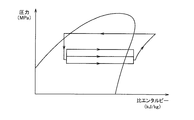
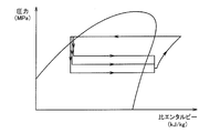
- FIG. 2 is a Mollier diagram showing the state of the refrigerant in the vapor compression refrigeration cycle 10.
- the horizontal axis in FIG. 2 indicates the specific enthalpy of the refrigerant, and the vertical axis indicates the absolute pressure of the refrigerant.
- the unit of specific enthalpy is kJ / kg, and the unit of absolute pressure is MPa.
- the curves in the figure are the saturated vapor line and saturated liquid line of the refrigerant.
- the refrigerant is sucked into the compressor 12 via the accumulator 60.
- the compressor 12 compresses the gas-phase refrigerant flowing from the accumulator 60.
- a receiver 62 is provided on the downstream side of the heat exchanger 14, and a refrigerant liquid in a supercooled liquid state is stored inside the receiver 62.
- the receiver 62 functions as a liquid reservoir that temporarily stores a refrigerant liquid that is a liquid refrigerant.
- a predetermined amount of refrigerant liquid is stored in the receiver 62, and the receiver 62 has a liquid storage function, so that it becomes a buffer against load fluctuation and absorbs load fluctuation. Therefore, since the flow rate of the refrigerant flowing to the cooling units 30 and 40 can be maintained even when the load changes, the cooling performance of the HV devices 31, 33, 41, and 43 can be stabilized.
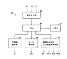
- the compressor control unit 85 receives the control command transmitted from the ECU 81, and transmits a signal C ⁇ b> 1 that instructs the start, stop, or rotation speed of the compressor 12 to the compressor 12.
- the motor control unit 86 receives the control command transmitted from the ECU 81, and transmits a signal M 1 for instructing the rotation speed of the motor 74 to the motor 74.
- the expansion valve and pressure regulating valve control unit 87 receives the control command transmitted from the ECU 81, transmits a signal RV1 for commanding the opening degree of the pressure regulating valve 19 to the pressure regulating valve 19, and sets the opening degree of the pressure regulating valve 39.
- a command signal RV 2 is transmitted to the pressure regulating valve 39, and a signal RV 3 that commands the opening degree of the pressure regulating valve 49 is transmitted to the pressure regulating valve 49.
- the pressure regulating valves 19, 39, and 49 are electric expansion valves that change the opening according to signals RV 1, RV 2, and RV 3 transmitted from the control unit 80.
- the expansion valve and pressure regulating valve control unit 87 also receives a control command transmitted from the ECU 81 and transmits a signal EV1 for commanding the opening degree of the expansion valve 16 to the expansion valve.
- the expansion valve 16 changes the opening according to the signal EV1 transmitted from the control unit 80.
- step (S20) it is determined whether or not the temperature of the refrigerant flowing through the cooling unit 30 exceeds the target temperature value. If it is determined in step (S20) that the temperature of the refrigerant exceeds the target value, then in step (S30), the opening of the pressure regulating valve 39 is increased. As the opening degree of the pressure regulating valve 39 is adjusted, the temperature of the refrigerant decreases in step (S40).
- the target value of the refrigerant temperature may be set as a specific value as a target value, or a specific temperature range having upper and lower limit values may be set as the target value.
- the refrigerant that cools the HV devices 31 and 33 in the cooling unit 30 flows into the cooling unit 30 in a gas-liquid two-phase state and is heated by heat exchange with the HV devices 31 and 33.
- the dryness increases, becoming dry saturated steam, and further becoming superheated steam.
- Most of the refrigerant flowing through the cooling passage 32 of the cooling unit 30 is in the state of wet vapor in a gas-liquid two-phase state.
- the temperature is low when the refrigerant pressure is low, and the temperature is high when the refrigerant pressure is high. That is, by increasing or decreasing the pressure of the gas-liquid two-phase refrigerant, the refrigerant temperature can be arbitrarily increased or decreased.
- step (S120) it is determined whether or not the degree of superheat of the refrigerant at the outlet of the cooling unit 30 exceeds the target value of the degree of superheat. If it is determined in step (S120) that the degree of superheat of the refrigerant exceeds the target value, then the opening degree of the control valve 37 is increased in step (S130). As the opening degree of the control valve 37 is adjusted, the flow rate of the refrigerant increases in step (S140).
- the target value of the superheat degree can be set so that, for example, the temperature difference between superheated steam and saturated steam under the same pressure is 3 to 5 ° C.
- the target value of superheat degree may set a specific superheat degree as a target value, and may set the range of the specific superheat degree which has an upper-lower limit value as a target value.
- the cooling device 1 that cools an electric device mounted on a vehicle has been described using the HV devices 31, 33, 41, and 43 as an example.
- the electric device is not limited to the exemplified electric device such as an inverter and a motor generator as long as it is an electric device that generates heat at least by operation, and may be any electric device.
- the target temperature range for cooling is a temperature range suitable as a temperature environment for operating the electrical equipment.
Landscapes
- Engineering & Computer Science (AREA)
- Physics & Mathematics (AREA)
- Mechanical Engineering (AREA)
- Thermal Sciences (AREA)
- General Engineering & Computer Science (AREA)
- Air-Conditioning For Vehicles (AREA)
Abstract
L'invention concerne un dispositif de refroidissement dans lequel il est possible d'améliorer l'invariabilité de la performance de refroidissement de sources de génération de chaleur au moyen d'un fluide frigorigène. Ce dispositif de refroidissement (1) permettant de refroidir un instrument (31, 33) de véhicule hybride comporte : un compresseur (12) qui comprime un fluide frigorigène ; un échangeur de chaleur (14) qui échange de la chaleur entre le fluide frigorigène et l'air extérieur ; une vanne de détente (16) qui décomprime le fluide frigorigène ; un échangeur de chaleur (18) qui échange de la chaleur entre le fluide frigorigène et l'air de conditionnement d'air ; une partie de refroidissement (30) qui est raccordée en parallèle à l'échangeur de chaleur (18) et qui refroidit l'instrument (31, 33) du véhicule hybride au moyen du fluide frigorigène ; une vanne de détente (19) qui est mise en œuvre du côté aval de l'échangeur de chaleur (18) et qui ajuste la pression du fluide frigorigène s'écoulant dans l'échangeur de chaleur (18) ; et une vanne de détente (39) qui est mise en œuvre du côté aval de la partie de refroidissement (30) et qui ajuste la pression du fluide frigorigène s'écoulant dans la partie de refroidissement (30). Le degré d'ouverture de la vanne de détente (19) est ajusté en fonction de la température du fluide frigorigène entre la vanne de détente (16) et la vanne de détente (19). Le degré d'ouverture de la vanne de détente (39) est ajusté en fonction de la température du fluide frigorigène entre la vanne de détente (16) et la vanne de détente (39).
Priority Applications (5)
| Application Number | Priority Date | Filing Date | Title |
|---|---|---|---|
| EP11878299.4A EP2796810A4 (fr) | 2011-12-19 | 2011-12-19 | Dispositif de refroidissement |
| US14/363,094 US20140326010A1 (en) | 2011-12-19 | 2011-12-19 | Cooling device |
| CN201180075616.XA CN103998874B (zh) | 2011-12-19 | 2011-12-19 | 冷却装置 |
| PCT/JP2011/079351 WO2013093991A1 (fr) | 2011-12-19 | 2011-12-19 | Dispositif de refroidissement |
| JP2013549970A JP5786957B2 (ja) | 2011-12-19 | 2011-12-19 | 冷却装置 |
Applications Claiming Priority (1)
| Application Number | Priority Date | Filing Date | Title |
|---|---|---|---|
| PCT/JP2011/079351 WO2013093991A1 (fr) | 2011-12-19 | 2011-12-19 | Dispositif de refroidissement |
Publications (1)
| Publication Number | Publication Date |
|---|---|
| WO2013093991A1 true WO2013093991A1 (fr) | 2013-06-27 |
Family
ID=48667922
Family Applications (1)
| Application Number | Title | Priority Date | Filing Date |
|---|---|---|---|
| PCT/JP2011/079351 WO2013093991A1 (fr) | 2011-12-19 | 2011-12-19 | Dispositif de refroidissement |
Country Status (5)
| Country | Link |
|---|---|
| US (1) | US20140326010A1 (fr) |
| EP (1) | EP2796810A4 (fr) |
| JP (1) | JP5786957B2 (fr) |
| CN (1) | CN103998874B (fr) |
| WO (1) | WO2013093991A1 (fr) |
Cited By (11)
| Publication number | Priority date | Publication date | Assignee | Title |
|---|---|---|---|---|
| WO2015105845A1 (fr) * | 2014-01-08 | 2015-07-16 | Carrier Corporation | Commande adaptative de système de réfrigération de transport à compartiments multiples |
| DE102014206770A1 (de) * | 2014-04-08 | 2015-10-08 | MAHLE Behr GmbH & Co. KG | Batteriekühleinrichtung und zugehöriges Betriebsverfahren |
| WO2017006775A1 (fr) * | 2015-07-08 | 2017-01-12 | 株式会社デンソー | Système de réfrigération et système de réfrigération embarqué dans un véhicule |
| CN107284193A (zh) * | 2016-03-31 | 2017-10-24 | 杭州三花研究院有限公司 | 空调系统、该空调系统的控制系统及控制方法 |
| JP2019129087A (ja) * | 2018-01-25 | 2019-08-01 | 株式会社デンソー | 電池冷却用冷凍サイクル装置 |
| JP2019219133A (ja) * | 2018-06-22 | 2019-12-26 | 株式会社デンソー | 冷凍サイクル装置 |
| JP2020507733A (ja) * | 2017-02-13 | 2020-03-12 | シーメンス アクチエンゲゼルシヤフトSiemens Aktiengesellschaft | ヒートポンプ設備の運転方法、ヒートポンプ設備、発電所、およびヒートポンプ設備を有する発電所 |
| WO2020166270A1 (fr) * | 2019-02-11 | 2020-08-20 | 株式会社デンソー | Dispositif à cycle frigorifique |
| JP2022501252A (ja) * | 2018-09-26 | 2022-01-06 | ヴァレオ システム テルミク | 車両用の冷媒回路 |
| FR3114051A1 (fr) * | 2020-09-15 | 2022-03-18 | Valeo Systemes Thermiques | Dispositif de gestion thermique de batteries d’un véhicule électrique ou hybride |
| WO2022201575A1 (fr) * | 2021-03-22 | 2022-09-29 | 株式会社アドテックス | Dispositif de génération de champ magnétique |
Families Citing this family (39)
| Publication number | Priority date | Publication date | Assignee | Title |
|---|---|---|---|---|
| DE102011053894A1 (de) * | 2010-11-23 | 2012-05-24 | Visteon Global Technologies, Inc. | Kälteanlage mit Kältemittelverdampferanordnung und Verfahren zur parallelen Luft- und Batteriekontaktkühlung |
| JP5798402B2 (ja) * | 2011-08-01 | 2015-10-21 | トヨタ自動車株式会社 | 冷却装置 |
| JP5370560B2 (ja) * | 2011-09-30 | 2013-12-18 | ダイキン工業株式会社 | 冷媒サイクルシステム |
| US9939185B2 (en) * | 2013-05-03 | 2018-04-10 | Parker-Hannifin Corporation | Indoor and outdoor ambient condition driven system |
| US10745136B2 (en) | 2013-08-29 | 2020-08-18 | Hamilton Sunstrand Corporation | Environmental control system including a compressing device |
| JP6171826B2 (ja) * | 2013-10-16 | 2017-08-02 | 富士通株式会社 | 電子装置、電子装置の制御方法及び電子装置の制御プログラム |
| JP6319018B2 (ja) * | 2014-09-25 | 2018-05-09 | マツダ株式会社 | エンジンの冷却システム |
| US10549860B2 (en) * | 2014-11-25 | 2020-02-04 | Hamilton Sundstrand Corporation | Environmental control system utilizing cabin air to drive a power turbine of an air cycle machine |
| US11466904B2 (en) | 2014-11-25 | 2022-10-11 | Hamilton Sundstrand Corporation | Environmental control system utilizing cabin air to drive a power turbine of an air cycle machine and utilizing multiple mix points for recirculation air in accordance with pressure mode |
| EP3032194A1 (fr) * | 2014-12-12 | 2016-06-15 | Danfoss A/S | Procédé pour commander une alimentation de réfrigérant vers un évaporateur comprenant le calcul d'une température de référence |
| CN104792053A (zh) * | 2015-04-28 | 2015-07-22 | 唐玉敏 | 一种双通道多级蒸发器热利用系统 |
| DE102015212550A1 (de) * | 2015-07-06 | 2017-01-12 | Bayerische Motoren Werke Aktiengesellschaft | Kältekreis, Verfahren zur Klimatisierung eines Fahrzeugs und Fahrzeug |
| DE102015216933A1 (de) | 2015-09-03 | 2017-03-09 | BSH Hausgeräte GmbH | Kältegerät mit mehreren Lagerkammern |
| JP6361703B2 (ja) * | 2015-09-04 | 2018-07-25 | 株式会社デンソー | 車両用熱管理装置 |
| CN107228450B (zh) * | 2016-03-23 | 2020-04-28 | 浙江三花汽车零部件有限公司 | 空调系统、该空调系统的控制系统及控制方法 |
| FR3051546A1 (fr) * | 2016-05-19 | 2017-11-24 | Valeo Systemes Thermiques | Circuit de fluide refrigerant agence pour controler thermiquement une source d'energie |
| CN109716051B (zh) * | 2016-10-06 | 2020-06-12 | 株式会社电装 | 设备温度调节装置 |
| CN106440443B (zh) * | 2016-11-25 | 2022-04-12 | 广州华凌制冷设备有限公司 | 一种适用高温制冷的空调系统及控制方法 |
| CN108116183B (zh) * | 2016-11-28 | 2024-03-12 | 杭州三花研究院有限公司 | 一种热管理系统的控制方法 |
| EP3604974A4 (fr) * | 2017-03-27 | 2020-04-22 | Daikin Industries, Ltd. | Échangeur de chaleur et dispositif frigorifique |
| DE102017120164A1 (de) * | 2017-09-01 | 2019-03-07 | Benteler Automobiltechnik Gmbh | Thermomanagementsystem für ein Elektrokraftfahrzeug |
| KR102253932B1 (ko) | 2017-10-06 | 2021-05-20 | 히타치 존슨 컨트롤즈 쿠쵸 가부시키가이샤 | 공기 조화기 |
| CN110398043B (zh) * | 2018-04-25 | 2022-06-14 | 三花控股集团有限公司 | 热管理系统及其控制方法 |
| DE102018209769B4 (de) * | 2018-06-18 | 2022-05-19 | Audi Ag | Verfahren zum Betreiben einer einen Kältemittelkreislauf aufweisenden Kälteanlage eines Fahrzeugs |
| DE102019201427B4 (de) | 2019-02-05 | 2022-01-13 | Audi Ag | Verfahren zum Betreiben eines Kältemittelkreislaufs einer Kälteanlage eines Fahrzeugs |
| DE102019201428A1 (de) * | 2019-02-05 | 2020-08-06 | Audi Ag | Verfahren zum Betreiben einer einen Kältemittelkreislauf aufweisenden Kälteanlage eines Fahrzeugs |
| DE102019203292B4 (de) * | 2019-03-12 | 2021-04-22 | Audi Ag | Verfahren zum Betreiben einer Kälteanlage für ein Fahrzeug mit einem eine Wärmepumpenfunktion aufweisenden Kältemittelkreislauf |
| DE102019113505A1 (de) * | 2019-05-21 | 2020-11-26 | Dr. Ing. H.C. F. Porsche Aktiengesellschaft | Kältekreislauf und Verfahren zur Kühlung von Kraftfahrzeugaggregaten |
| US11267318B2 (en) * | 2019-11-26 | 2022-03-08 | Ford Global Technologies, Llc | Vapor injection heat pump system and controls |
| EP3862201A1 (fr) * | 2020-02-06 | 2021-08-11 | Belenos Clean Power Holding AG | Dispositif de récuperation et de régulation d' énergie thermique d'un véhicule électrique à génerateur électrochimique avec un système hvac |
| JP7185120B2 (ja) * | 2020-03-26 | 2022-12-07 | 株式会社鷺宮製作所 | 冷却装置 |
| FR3110878B1 (fr) * | 2020-05-27 | 2022-06-24 | Valeo Systemes Thermiques | Procédé de contrôle d’un système de conditionnement thermique pour véhicule automobile |
| CN113587479A (zh) * | 2020-06-28 | 2021-11-02 | 李华玉 | 第二类单工质联合循环 |
| CN113587480A (zh) * | 2020-06-28 | 2021-11-02 | 李华玉 | 第二类单工质联合循环 |
| WO2022007375A1 (fr) * | 2020-07-10 | 2022-01-13 | 李华玉 | Cycle combiné de milieu de travail unique de second type |
| CN112556259B (zh) * | 2020-12-14 | 2021-11-30 | 珠海格力电器股份有限公司 | 一种压力调节控制方法、装置及空调器 |
| FR3117955B1 (fr) * | 2020-12-18 | 2023-06-02 | Renault Sas | Système de refroidissement et système de gestion thermique pour un véhicule automobile. |
| CN113891641B (zh) * | 2021-12-08 | 2022-03-22 | 山东理工职业学院 | 用于船舶电子设备的液冷系统及其调节方法 |
| EP4361526A1 (fr) * | 2022-10-28 | 2024-05-01 | Carrier Corporation | Système de réfrigération |
Citations (10)
| Publication number | Priority date | Publication date | Assignee | Title |
|---|---|---|---|---|
| JPS62253511A (ja) * | 1986-04-25 | 1987-11-05 | Toyo Radiator Kk | 自動車用冷房装置 |
| JPH03113247A (ja) * | 1989-09-27 | 1991-05-14 | Hitachi Ltd | マルチ冷凍サイクル |
| JPH04251164A (ja) * | 1991-01-08 | 1992-09-07 | Toshiba Corp | 冷凍サイクル装置 |
| JPH09290622A (ja) | 1996-04-24 | 1997-11-11 | Denso Corp | 車両用空調装置 |
| JPH1123081A (ja) | 1997-07-01 | 1999-01-26 | Denso Corp | 発熱機器の冷却器を有する空調装置 |
| JP2001309506A (ja) | 2000-04-25 | 2001-11-02 | Denso Corp | 車両走行モ−タ駆動用インバータ回路装置及びその冷却方法 |
| JP2003222420A (ja) * | 2002-01-30 | 2003-08-08 | Ingersoll Rand Kk | 冷凍機 |
| JP2005082066A (ja) | 2003-09-10 | 2005-03-31 | Toyota Motor Corp | 冷却システム |
| JP2007069733A (ja) | 2005-09-07 | 2007-03-22 | Valeo Thermal Systems Japan Corp | 車両用空調装置を利用した発熱体冷却システム |
| JP2009236330A (ja) * | 2008-03-25 | 2009-10-15 | Calsonic Kansei Corp | 冷却システム |
Family Cites Families (18)
| Publication number | Priority date | Publication date | Assignee | Title |
|---|---|---|---|---|
| US2924079A (en) * | 1958-06-09 | 1960-02-09 | Sporlan Valve Company Inc | Reversible cycle refrigeration system |
| US3242688A (en) * | 1963-08-29 | 1966-03-29 | Jackes Evans Mfg Company | Control means and refrigeration system therefor |
| JPH02126052A (ja) * | 1988-11-02 | 1990-05-15 | Nissin Kogyo Kk | ヘアーピンコイル型蒸発器における冷媒供給量の制御装置 |
| JPH07120091A (ja) * | 1993-10-26 | 1995-05-12 | Toshiba Ave Corp | 空気調和機 |
| FR2713320B1 (fr) * | 1993-12-02 | 1996-02-02 | Mc International | Procédé de commande et de dégivrage en continu d'un échangeur frigorifique et installation équipée d'un tel échangeur. |
| KR100274257B1 (ko) * | 1998-04-06 | 2001-03-02 | 윤종용 | 냉매량 조절을 위한 바이패스 부를 가지는 멀티 에어컨 |
| AU2712301A (en) * | 2000-06-07 | 2001-12-17 | Samsung Electronics Co., Ltd. | Control system of degree of superheat of air conditioner and control method thereof |
| US6804972B2 (en) * | 2001-12-10 | 2004-10-19 | Carrier Corporation | Direct drive multi-temperature special evaporators |
| EP1510763B1 (fr) * | 2002-05-31 | 2012-02-01 | JFE Engineering Corporation | Dispositif de production de bouillie d'hydrate |
| JP2004198002A (ja) * | 2002-12-17 | 2004-07-15 | Denso Corp | 蒸気圧縮式冷凍機 |
| US20040118144A1 (en) * | 2002-12-20 | 2004-06-24 | Hsu John S. | Hermetic inverter/converter chamber with multiple pressure and cooling zones |
| US20060090505A1 (en) * | 2004-10-28 | 2006-05-04 | Carrier Corporation | Refrigerant cycle with tandem compressors for multi-level cooling |
| US20060130494A1 (en) * | 2004-12-20 | 2006-06-22 | Serge Dube | Defrost refrigeration system |
| US7797957B2 (en) * | 2006-04-12 | 2010-09-21 | Hussmann Corporation | Methods and apparatus for linearized temperature control of commercial refrigeration systems |
| ES2689315T3 (es) * | 2006-05-26 | 2018-11-13 | Carrier Corporation | Control de sobrecalentamiento para sistemas de HVAC&R |
| US7757505B2 (en) * | 2006-11-02 | 2010-07-20 | Hussmann Corporation | Predictive capacity systems and methods for commercial refrigeration |
| US7992398B2 (en) * | 2008-07-16 | 2011-08-09 | Honeywell International Inc. | Refrigeration control system |
| US20130025304A1 (en) * | 2011-07-27 | 2013-01-31 | Dorman Dennis R | Loading and unloading of compressors in a cooling system |
-
2011
- 2011-12-19 WO PCT/JP2011/079351 patent/WO2013093991A1/fr active Application Filing
- 2011-12-19 JP JP2013549970A patent/JP5786957B2/ja active Active
- 2011-12-19 CN CN201180075616.XA patent/CN103998874B/zh not_active Expired - Fee Related
- 2011-12-19 US US14/363,094 patent/US20140326010A1/en not_active Abandoned
- 2011-12-19 EP EP11878299.4A patent/EP2796810A4/fr not_active Withdrawn
Patent Citations (10)
| Publication number | Priority date | Publication date | Assignee | Title |
|---|---|---|---|---|
| JPS62253511A (ja) * | 1986-04-25 | 1987-11-05 | Toyo Radiator Kk | 自動車用冷房装置 |
| JPH03113247A (ja) * | 1989-09-27 | 1991-05-14 | Hitachi Ltd | マルチ冷凍サイクル |
| JPH04251164A (ja) * | 1991-01-08 | 1992-09-07 | Toshiba Corp | 冷凍サイクル装置 |
| JPH09290622A (ja) | 1996-04-24 | 1997-11-11 | Denso Corp | 車両用空調装置 |
| JPH1123081A (ja) | 1997-07-01 | 1999-01-26 | Denso Corp | 発熱機器の冷却器を有する空調装置 |
| JP2001309506A (ja) | 2000-04-25 | 2001-11-02 | Denso Corp | 車両走行モ−タ駆動用インバータ回路装置及びその冷却方法 |
| JP2003222420A (ja) * | 2002-01-30 | 2003-08-08 | Ingersoll Rand Kk | 冷凍機 |
| JP2005082066A (ja) | 2003-09-10 | 2005-03-31 | Toyota Motor Corp | 冷却システム |
| JP2007069733A (ja) | 2005-09-07 | 2007-03-22 | Valeo Thermal Systems Japan Corp | 車両用空調装置を利用した発熱体冷却システム |
| JP2009236330A (ja) * | 2008-03-25 | 2009-10-15 | Calsonic Kansei Corp | 冷却システム |
Non-Patent Citations (1)
| Title |
|---|
| See also references of EP2796810A4 |
Cited By (26)
| Publication number | Priority date | Publication date | Assignee | Title |
|---|---|---|---|---|
| US10337767B2 (en) | 2014-01-08 | 2019-07-02 | Carrier Corporation | Adaptive control of multi-compartment transport refrigeration system |
| WO2015105845A1 (fr) * | 2014-01-08 | 2015-07-16 | Carrier Corporation | Commande adaptative de système de réfrigération de transport à compartiments multiples |
| DE102014206770A1 (de) * | 2014-04-08 | 2015-10-08 | MAHLE Behr GmbH & Co. KG | Batteriekühleinrichtung und zugehöriges Betriebsverfahren |
| US20150283874A1 (en) * | 2014-04-08 | 2015-10-08 | MAHLE Behr GmbH & Co. KG | Battery cooling device and associated operating method |
| US10562366B2 (en) | 2014-04-08 | 2020-02-18 | MAHLE Behr GmbH & Co. KG | Battery cooling device and associated operating method |
| WO2017006775A1 (fr) * | 2015-07-08 | 2017-01-12 | 株式会社デンソー | Système de réfrigération et système de réfrigération embarqué dans un véhicule |
| US10414244B2 (en) | 2015-07-08 | 2019-09-17 | Denso Corporation | Refrigeration system, and in-vehicle refrigeration system |
| JP2019510190A (ja) * | 2016-03-31 | 2019-04-11 | 杭州三花研究院有限公司Hangzhou Sanhua Research Institute Co.,Ltd. | 空調システムならびに空調システム用の制御システムおよび制御方法 |
| KR102192470B1 (ko) * | 2016-03-31 | 2020-12-17 | 항저우 산후아 리서치 인스티튜트 컴퍼니 리미티드 | 공기 조화 시스템, 그리고 공기 조화 시스템에 대한 제어 시스템 및 제어 방법 |
| US11231213B2 (en) | 2016-03-31 | 2022-01-25 | Hangzhou Sanhua Research Institute Co., Ltd. | Air conditioning system, control system, and control method for air conditioning system expansion valve |
| KR20180123152A (ko) * | 2016-03-31 | 2018-11-14 | 항저우 산후아 리서치 인스티튜트 컴퍼니 리미티드 | 공기 조화 시스템, 그리고 공기 조화 시스템에 대한 제어 시스템 및 제어 방법 |
| CN107284193A (zh) * | 2016-03-31 | 2017-10-24 | 杭州三花研究院有限公司 | 空调系统、该空调系统的控制系统及控制方法 |
| JP2020507733A (ja) * | 2017-02-13 | 2020-03-12 | シーメンス アクチエンゲゼルシヤフトSiemens Aktiengesellschaft | ヒートポンプ設備の運転方法、ヒートポンプ設備、発電所、およびヒートポンプ設備を有する発電所 |
| US11509007B2 (en) | 2018-01-25 | 2022-11-22 | Denso Corporation | Refrigeration cycle device for cooling battery |
| JP2019129087A (ja) * | 2018-01-25 | 2019-08-01 | 株式会社デンソー | 電池冷却用冷凍サイクル装置 |
| WO2019146240A1 (fr) * | 2018-01-25 | 2019-08-01 | 株式会社デンソー | Dispositif à cycle de réfrigération pour le refroidissement de batteries |
| JP2019219133A (ja) * | 2018-06-22 | 2019-12-26 | 株式会社デンソー | 冷凍サイクル装置 |
| JP7028079B2 (ja) | 2018-06-22 | 2022-03-02 | 株式会社デンソー | 冷凍サイクル装置 |
| JP7198916B2 (ja) | 2018-09-26 | 2023-01-04 | ヴァレオ システム テルミク | 車両用の冷媒回路 |
| JP2022501252A (ja) * | 2018-09-26 | 2022-01-06 | ヴァレオ システム テルミク | 車両用の冷媒回路 |
| JP2020128857A (ja) * | 2019-02-11 | 2020-08-27 | 株式会社デンソー | 冷凍サイクル装置 |
| WO2020166270A1 (fr) * | 2019-02-11 | 2020-08-20 | 株式会社デンソー | Dispositif à cycle frigorifique |
| JP7275621B2 (ja) | 2019-02-11 | 2023-05-18 | 株式会社デンソー | 冷凍サイクル装置 |
| WO2022058215A1 (fr) * | 2020-09-15 | 2022-03-24 | Valeo Systemes Thermiques | Dispositif de gestion thermique de batteries d'un véhicule électrique ou hybride |
| FR3114051A1 (fr) * | 2020-09-15 | 2022-03-18 | Valeo Systemes Thermiques | Dispositif de gestion thermique de batteries d’un véhicule électrique ou hybride |
| WO2022201575A1 (fr) * | 2021-03-22 | 2022-09-29 | 株式会社アドテックス | Dispositif de génération de champ magnétique |
Also Published As
| Publication number | Publication date |
|---|---|
| EP2796810A1 (fr) | 2014-10-29 |
| JP5786957B2 (ja) | 2015-09-30 |
| US20140326010A1 (en) | 2014-11-06 |
| JPWO2013093991A1 (ja) | 2015-04-27 |
| CN103998874A (zh) | 2014-08-20 |
| EP2796810A4 (fr) | 2016-03-16 |
| CN103998874B (zh) | 2016-07-06 |
Similar Documents
| Publication | Publication Date | Title |
|---|---|---|
| JP5786957B2 (ja) | 冷却装置 | |
| JP5655954B2 (ja) | 冷却装置および冷却装置の制御方法 | |
| JP5989328B2 (ja) | 熱交換装置 | |
| EP2678175B1 (fr) | Système de refroidissement de véhicule | |
| EP2709864B1 (fr) | Système de refroidissement | |
| EP2694303B1 (fr) | Appareil de refroidissement | |
| WO2012105047A1 (fr) | Dispositif de refroidissement | |
| US9631544B2 (en) | Cooling system and vehicle that includes cooling system | |
| EP2755834B1 (fr) | Appareil d'échange de chaleur et son procédé de commande | |
| WO2013051114A1 (fr) | Procédé de commande pour appareil de refroidissement | |
| JP5837369B2 (ja) | 冷却装置の制御装置および制御方法 | |
| US20150027162A1 (en) | Cooling system | |
| JP2012245857A (ja) | 冷却装置、冷却装置の制御方法および制御装置 | |
| JP5320419B2 (ja) | 冷却装置 | |
| JP2014184795A (ja) | 温度調節装置の制御方法 | |
| JP5618011B2 (ja) | 冷却装置の制御方法 | |
| JP5917966B2 (ja) | 冷却装置およびそれを備える車両 | |
| JP2014081127A (ja) | 冷却装置およびその制御方法 | |
| JP2014088996A (ja) | 冷却装置 |
Legal Events
| Date | Code | Title | Description |
|---|---|---|---|
| 121 | Ep: the epo has been informed by wipo that ep was designated in this application |
Ref document number: 11878299 Country of ref document: EP Kind code of ref document: A1 |
|
| ENP | Entry into the national phase |
Ref document number: 2013549970 Country of ref document: JP Kind code of ref document: A |
|
| WWE | Wipo information: entry into national phase |
Ref document number: 2011878299 Country of ref document: EP |
|
| NENP | Non-entry into the national phase |
Ref country code: DE |