WO2013093991A1 - Cooling device - Google Patents
Cooling device Download PDFInfo
- Publication number
- WO2013093991A1 WO2013093991A1 PCT/JP2011/079351 JP2011079351W WO2013093991A1 WO 2013093991 A1 WO2013093991 A1 WO 2013093991A1 JP 2011079351 W JP2011079351 W JP 2011079351W WO 2013093991 A1 WO2013093991 A1 WO 2013093991A1
- Authority
- WO
- WIPO (PCT)
- Prior art keywords
- refrigerant
- cooling
- heat exchanger
- pressure
- valve
- Prior art date
Links
- 238000001816 cooling Methods 0.000 title claims abstract description 323
- 239000003507 refrigerant Substances 0.000 claims abstract description 615
- 238000004378 air conditioning Methods 0.000 claims abstract description 25
- 230000001105 regulatory effect Effects 0.000 claims description 79
- 239000007788 liquid Substances 0.000 claims description 48
- 230000003247 decreasing effect Effects 0.000 claims description 28
- 239000003638 chemical reducing agent Substances 0.000 claims description 12
- 238000000926 separation method Methods 0.000 claims description 2
- 239000003570 air Substances 0.000 description 44
- 238000005057 refrigeration Methods 0.000 description 31
- 230000006835 compression Effects 0.000 description 28
- 238000007906 compression Methods 0.000 description 28
- 238000001514 detection method Methods 0.000 description 24
- 239000012071 phase Substances 0.000 description 23
- 239000007789 gas Substances 0.000 description 16
- 239000007791 liquid phase Substances 0.000 description 15
- 230000001276 controlling effect Effects 0.000 description 14
- 238000010586 diagram Methods 0.000 description 14
- 230000008859 change Effects 0.000 description 12
- 230000006870 function Effects 0.000 description 11
- 230000020169 heat generation Effects 0.000 description 10
- 229920006395 saturated elastomer Polymers 0.000 description 9
- 238000000034 method Methods 0.000 description 8
- 238000011144 upstream manufacturing Methods 0.000 description 7
- 230000007423 decrease Effects 0.000 description 6
- 238000010438 heat treatment Methods 0.000 description 5
- 230000008016 vaporization Effects 0.000 description 5
- 239000011555 saturated liquid Substances 0.000 description 4
- 239000013526 supercooled liquid Substances 0.000 description 4
- 238000009834 vaporization Methods 0.000 description 4
- 238000013459 approach Methods 0.000 description 3
- 238000001704 evaporation Methods 0.000 description 3
- 230000008020 evaporation Effects 0.000 description 3
- 230000002093 peripheral effect Effects 0.000 description 3
- 230000004044 response Effects 0.000 description 3
- 238000009423 ventilation Methods 0.000 description 3
- QGZKDVFQNNGYKY-UHFFFAOYSA-N Ammonia Chemical compound N QGZKDVFQNNGYKY-UHFFFAOYSA-N 0.000 description 2
- CURLTUGMZLYLDI-UHFFFAOYSA-N Carbon dioxide Chemical compound O=C=O CURLTUGMZLYLDI-UHFFFAOYSA-N 0.000 description 2
- ATUOYWHBWRKTHZ-UHFFFAOYSA-N Propane Chemical compound CCC ATUOYWHBWRKTHZ-UHFFFAOYSA-N 0.000 description 2
- 239000003990 capacitor Substances 0.000 description 2
- 238000009833 condensation Methods 0.000 description 2
- 230000005494 condensation Effects 0.000 description 2
- 239000002826 coolant Substances 0.000 description 2
- NNPPMTNAJDCUHE-UHFFFAOYSA-N isobutane Chemical compound CC(C)C NNPPMTNAJDCUHE-UHFFFAOYSA-N 0.000 description 2
- 239000003595 mist Substances 0.000 description 2
- 230000008569 process Effects 0.000 description 2
- 238000003860 storage Methods 0.000 description 2
- XLYOFNOQVPJJNP-UHFFFAOYSA-N water Substances O XLYOFNOQVPJJNP-UHFFFAOYSA-N 0.000 description 2
- HBBGRARXTFLTSG-UHFFFAOYSA-N Lithium ion Chemical compound [Li+] HBBGRARXTFLTSG-UHFFFAOYSA-N 0.000 description 1
- 239000012080 ambient air Substances 0.000 description 1
- 229910021529 ammonia Inorganic materials 0.000 description 1
- 229910002092 carbon dioxide Inorganic materials 0.000 description 1
- 239000001569 carbon dioxide Substances 0.000 description 1
- 238000002485 combustion reaction Methods 0.000 description 1
- 238000007599 discharging Methods 0.000 description 1
- 238000009826 distribution Methods 0.000 description 1
- 230000007613 environmental effect Effects 0.000 description 1
- 239000000446 fuel Substances 0.000 description 1
- 229930195733 hydrocarbon Natural products 0.000 description 1
- 150000002430 hydrocarbons Chemical class 0.000 description 1
- 238000002347 injection Methods 0.000 description 1
- 239000007924 injection Substances 0.000 description 1
- 239000001282 iso-butane Substances 0.000 description 1
- 229910001416 lithium ion Inorganic materials 0.000 description 1
- 238000004519 manufacturing process Methods 0.000 description 1
- 229910052987 metal hydride Inorganic materials 0.000 description 1
- 239000000203 mixture Substances 0.000 description 1
- 238000012986 modification Methods 0.000 description 1
- 230000004048 modification Effects 0.000 description 1
- 229910052759 nickel Inorganic materials 0.000 description 1
- PXHVJJICTQNCMI-UHFFFAOYSA-N nickel Substances [Ni] PXHVJJICTQNCMI-UHFFFAOYSA-N 0.000 description 1
- -1 nickel metal hydride Chemical class 0.000 description 1
- 238000013021 overheating Methods 0.000 description 1
- 239000001294 propane Substances 0.000 description 1
- 230000002040 relaxant effect Effects 0.000 description 1
- 238000012546 transfer Methods 0.000 description 1
- 239000002918 waste heat Substances 0.000 description 1
Images


Classifications
-
- F—MECHANICAL ENGINEERING; LIGHTING; HEATING; WEAPONS; BLASTING
- F25—REFRIGERATION OR COOLING; COMBINED HEATING AND REFRIGERATION SYSTEMS; HEAT PUMP SYSTEMS; MANUFACTURE OR STORAGE OF ICE; LIQUEFACTION SOLIDIFICATION OF GASES
- F25B—REFRIGERATION MACHINES, PLANTS OR SYSTEMS; COMBINED HEATING AND REFRIGERATION SYSTEMS; HEAT PUMP SYSTEMS
- F25B41/00—Fluid-circulation arrangements
- F25B41/20—Disposition of valves, e.g. of on-off valves or flow control valves
-
- B—PERFORMING OPERATIONS; TRANSPORTING
- B60—VEHICLES IN GENERAL
- B60H—ARRANGEMENTS OF HEATING, COOLING, VENTILATING OR OTHER AIR-TREATING DEVICES SPECIALLY ADAPTED FOR PASSENGER OR GOODS SPACES OF VEHICLES
- B60H1/00—Heating, cooling or ventilating [HVAC] devices
- B60H1/00271—HVAC devices specially adapted for particular vehicle parts or components and being connected to the vehicle HVAC unit
-
- B—PERFORMING OPERATIONS; TRANSPORTING
- B60—VEHICLES IN GENERAL
- B60H—ARRANGEMENTS OF HEATING, COOLING, VENTILATING OR OTHER AIR-TREATING DEVICES SPECIALLY ADAPTED FOR PASSENGER OR GOODS SPACES OF VEHICLES
- B60H1/00—Heating, cooling or ventilating [HVAC] devices
- B60H1/32—Cooling devices
- B60H1/3204—Cooling devices using compression
- B60H1/323—Cooling devices using compression characterised by comprising auxiliary or multiple systems, e.g. plurality of evaporators, or by involving auxiliary cooling devices
-
- F—MECHANICAL ENGINEERING; LIGHTING; HEATING; WEAPONS; BLASTING
- F25—REFRIGERATION OR COOLING; COMBINED HEATING AND REFRIGERATION SYSTEMS; HEAT PUMP SYSTEMS; MANUFACTURE OR STORAGE OF ICE; LIQUEFACTION SOLIDIFICATION OF GASES
- F25B—REFRIGERATION MACHINES, PLANTS OR SYSTEMS; COMBINED HEATING AND REFRIGERATION SYSTEMS; HEAT PUMP SYSTEMS
- F25B31/00—Compressor arrangements
- F25B31/006—Cooling of compressor or motor
-
- F—MECHANICAL ENGINEERING; LIGHTING; HEATING; WEAPONS; BLASTING
- F25—REFRIGERATION OR COOLING; COMBINED HEATING AND REFRIGERATION SYSTEMS; HEAT PUMP SYSTEMS; MANUFACTURE OR STORAGE OF ICE; LIQUEFACTION SOLIDIFICATION OF GASES
- F25B—REFRIGERATION MACHINES, PLANTS OR SYSTEMS; COMBINED HEATING AND REFRIGERATION SYSTEMS; HEAT PUMP SYSTEMS
- F25B41/00—Fluid-circulation arrangements
- F25B41/30—Expansion means; Dispositions thereof
- F25B41/31—Expansion valves
- F25B41/34—Expansion valves with the valve member being actuated by electric means, e.g. by piezoelectric actuators
-
- F—MECHANICAL ENGINEERING; LIGHTING; HEATING; WEAPONS; BLASTING
- F25—REFRIGERATION OR COOLING; COMBINED HEATING AND REFRIGERATION SYSTEMS; HEAT PUMP SYSTEMS; MANUFACTURE OR STORAGE OF ICE; LIQUEFACTION SOLIDIFICATION OF GASES
- F25B—REFRIGERATION MACHINES, PLANTS OR SYSTEMS; COMBINED HEATING AND REFRIGERATION SYSTEMS; HEAT PUMP SYSTEMS
- F25B49/00—Arrangement or mounting of control or safety devices
- F25B49/02—Arrangement or mounting of control or safety devices for compression type machines, plants or systems
-
- B—PERFORMING OPERATIONS; TRANSPORTING
- B60—VEHICLES IN GENERAL
- B60H—ARRANGEMENTS OF HEATING, COOLING, VENTILATING OR OTHER AIR-TREATING DEVICES SPECIALLY ADAPTED FOR PASSENGER OR GOODS SPACES OF VEHICLES
- B60H1/00—Heating, cooling or ventilating [HVAC] devices
- B60H1/00271—HVAC devices specially adapted for particular vehicle parts or components and being connected to the vehicle HVAC unit
- B60H2001/00307—Component temperature regulation using a liquid flow
-
- B—PERFORMING OPERATIONS; TRANSPORTING
- B60—VEHICLES IN GENERAL
- B60H—ARRANGEMENTS OF HEATING, COOLING, VENTILATING OR OTHER AIR-TREATING DEVICES SPECIALLY ADAPTED FOR PASSENGER OR GOODS SPACES OF VEHICLES
- B60H1/00—Heating, cooling or ventilating [HVAC] devices
- B60H1/32—Cooling devices
- B60H2001/3269—Cooling devices output of a control signal
- B60H2001/3285—Cooling devices output of a control signal related to an expansion unit
-
- F—MECHANICAL ENGINEERING; LIGHTING; HEATING; WEAPONS; BLASTING
- F25—REFRIGERATION OR COOLING; COMBINED HEATING AND REFRIGERATION SYSTEMS; HEAT PUMP SYSTEMS; MANUFACTURE OR STORAGE OF ICE; LIQUEFACTION SOLIDIFICATION OF GASES
- F25B—REFRIGERATION MACHINES, PLANTS OR SYSTEMS; COMBINED HEATING AND REFRIGERATION SYSTEMS; HEAT PUMP SYSTEMS
- F25B5/00—Compression machines, plants or systems, with several evaporator circuits, e.g. for varying refrigerating capacity
- F25B5/02—Compression machines, plants or systems, with several evaporator circuits, e.g. for varying refrigerating capacity arranged in parallel
-
- Y—GENERAL TAGGING OF NEW TECHNOLOGICAL DEVELOPMENTS; GENERAL TAGGING OF CROSS-SECTIONAL TECHNOLOGIES SPANNING OVER SEVERAL SECTIONS OF THE IPC; TECHNICAL SUBJECTS COVERED BY FORMER USPC CROSS-REFERENCE ART COLLECTIONS [XRACs] AND DIGESTS
- Y02—TECHNOLOGIES OR APPLICATIONS FOR MITIGATION OR ADAPTATION AGAINST CLIMATE CHANGE
- Y02B—CLIMATE CHANGE MITIGATION TECHNOLOGIES RELATED TO BUILDINGS, e.g. HOUSING, HOUSE APPLIANCES OR RELATED END-USER APPLICATIONS
- Y02B30/00—Energy efficient heating, ventilation or air conditioning [HVAC]
- Y02B30/70—Efficient control or regulation technologies, e.g. for control of refrigerant flow, motor or heating
Definitions
- the present invention has been made in view of the above-mentioned problems, and a main object thereof is to provide a cooling device that can improve the uniformity of the cooling capacity of the heat generation source by the refrigerant.
- the opening degree of the first pressure regulating valve is adjusted according to the temperature of the refrigerant between the pressure reducer and the first pressure regulating valve.
- the opening of the second pressure regulating valve is adjusted according to the temperature of the refrigerant between the pressure reducer and the second pressure regulating valve.
- the decompressor includes a first flow control valve that adjusts a flow rate of the refrigerant flowing into the second heat exchanger, and a second flow rate control valve that adjusts the flow rate of the refrigerant flowing into the cooling unit. Including.
- the first flow control valve increases the valve opening when the degree of superheat of the refrigerant on the outlet side of the second heat exchanger is higher than a set value, and increases the valve opening degree on the outlet side of the second heat exchanger.
- the valve opening is decreased, and the second flow rate control valve increases the valve opening when the degree of superheat of the refrigerant on the outlet side of the cooling unit is higher than the set value, thereby cooling
- the valve opening is decreased.
- the vapor compression refrigeration cycle 10 includes a compressor 12, a heat exchanger 14 as a first heat exchanger, an expansion valve 16 as an example of a decompressor, a heat exchanger 18 as a second heat exchanger, including.
- the compressor 12 operates with a motor or engine mounted on the vehicle as a power source, and compresses the refrigerant gas in an adiabatic manner to form an overheated refrigerant gas.
- the compressor 12 sucks and compresses the refrigerant flowing from the heat exchanger 18 when the vapor compression refrigeration cycle 10 is operated, and discharges a high-temperature and high-pressure gas-phase refrigerant into the refrigerant passage 21.
- the compressor 12 circulates the refrigerant in the vapor compression refrigeration cycle 10 by discharging the refrigerant into the refrigerant passage 21.
- the expansion valve 16 expands by injecting a high-pressure liquid refrigerant flowing through the refrigerant passage 25 from a small hole, and changes the low-temperature / low-pressure mist refrigerant.
- the expansion valve 16 depressurizes the refrigerant liquid condensed by the heat exchanger 14 to obtain wet vapor in a gas-liquid mixed state.
- the decompressor for decompressing the refrigerant liquid is not limited to the expansion valve 16 that is throttled and expanded, and may be a capillary tube or a control valve capable of controlling the opening degree.
- An accumulator 60 is disposed on the refrigerant path between the heat exchanger 18 and the compressor 12.
- the accumulator 60 separates the refrigerant flowing out from the heat exchanger 18 into a gas phase refrigerant and a liquid phase refrigerant.
- a refrigerant liquid that is a liquid phase refrigerant and a refrigerant vapor that is a gas phase refrigerant can be stored inside the accumulator 60.
- a refrigerant passage 26 and a refrigerant passage 27 are connected to the accumulator 60.
- the end of the refrigerant passage 27 connected to the gas phase side of the accumulator 60 forms an outlet for the gas phase refrigerant from the accumulator 60.
- refrigerant liquid accumulates on the lower side and refrigerant vapor accumulates on the upper side.
- An end portion of the refrigerant passage 27 for leading the refrigerant vapor from the accumulator 60 is connected to a ceiling portion of the accumulator 60. Only the refrigerant vapor is sent out of the accumulator 60 from the ceiling side of the accumulator 60 via the refrigerant passage 27. Thereby, the accumulator 60 can reliably separate the gas-phase refrigerant and the liquid-phase refrigerant.
- the refrigerant passage 25 is provided with a temperature detection unit 52 that detects the temperature of the refrigerant that flows out of the heat exchanger 18 and flows through the refrigerant passage 25. Based on the temperature of the refrigerant detected by the temperature detector 52, the opening degree of the pressure regulating valve 19 is controlled. Specifically, when the temperature of the refrigerant flowing through the refrigerant passage 25 is higher than the target value, the opening degree of the pressure adjustment valve 19 is increased, and when the temperature of the refrigerant flowing through the refrigerant passage 25 is lower than the target value, the pressure adjustment is performed. The opening degree of the valve 19 is decreased.
- the refrigerant that has flowed out of the heat exchanger 14 is supplied to the receiver 62 through the refrigerant passage 22.
- the refrigerant flowing into the receiver 62 from the refrigerant passage 22 is separated into a gas phase and a liquid phase inside the receiver 62.
- the receiver 62 separates the refrigerant into a liquid refrigerant liquid and a gaseous refrigerant vapor. And store temporarily.
- the gas-liquid separated refrigerant liquid flows out of the receiver 62 via the refrigerant passage 23.
- the end of the refrigerant passage 23 connected to the liquid phase side of the receiver 62 forms an outlet for the liquid phase refrigerant from the receiver 62.
- the refrigerant liquid accumulates on the lower side and the refrigerant vapor accumulates on the upper side.
- An end portion of the refrigerant passage 23 for leading the refrigerant liquid from the receiver 62 is connected to the bottom portion of the receiver 62. Only the refrigerant liquid is sent out of the receiver 62 from the bottom side of the receiver 62 via the refrigerant passage 23. Thereby, the receiver 62 can reliably separate the gas-phase refrigerant and the liquid-phase refrigerant.
- Cooling units 30 and 40 connected in parallel with the heat exchanger 18 are provided on the path of the refrigerant flowing from the expansion valve 16 toward the accumulator 60.
- the cooling device 1 includes a refrigerant path connected in parallel with the heat exchanger 18, and the cooling units 30 and 40 are provided on the refrigerant path.
- the heat exchanger 18 is provided in one of a plurality of passages connected in parallel in the path of the refrigerant flowing between the expansion valve 16 and the accumulator 60, and the other one of the plurality of paths is cooled.
- the part 30 is provided, and the cooling part 40 is provided in yet another one of the plurality of passages.
- the refrigerant passages 34 and 44 are branched from the refrigerant passage 24 between the expansion valve 16 and the heat exchanger 18.
- the refrigerant passage 34 communicates the refrigerant passage 24 and the cooling unit 30.
- the refrigerant flows from the refrigerant passage 24 to the cooling unit 30 via the refrigerant passage 34.
- the refrigerant passage 44 communicates the refrigerant passage 24 and the cooling unit 40.
- the refrigerant flows from the refrigerant passage 24 to the cooling unit 40 via the refrigerant passage 44.
- the cooling unit 30 includes HV (Hybrid Vehicle) devices 31 and 33 that are electric devices mounted on an electric vehicle, and a cooling passage 32 that is a pipe through which a refrigerant flows.
- the cooling unit 40 includes HV devices 41 and 43 that are electric devices mounted on an electric vehicle, and a cooling passage 42 that is a pipe through which a refrigerant flows.
- the HV devices 31, 33, 41, and 43 are examples of heat generation sources that generate heat when power is transferred.
- the HV devices 31, 33, 41, 43 include, for example, an inverter for converting DC power to AC power, a motor generator that is a rotating electrical machine, a battery that is a power storage device, a boost converter that boosts the voltage of the battery, and a battery. Including at least one of a DC / DC converter and the like for stepping down the voltage.
- the battery is a secondary battery such as a lithium ion battery or a nickel metal hydride battery.
- a capacitor may be used instead of the battery.
- the HV device 31 and the HV device 33 may be inverters
- the HV device 41 may be a battery
- the HV device 43 may be a capacitor.
- the refrigerant liquid flowing out from the receiver 62 flows toward the cooling unit 30 via the refrigerant passage 34 and flows toward the cooling unit 40 via the refrigerant passage 44.
- the refrigerant that reaches the cooling units 30 and 40 and flows through the cooling passages 32 and 42 cools the refrigerant by taking heat from each of the HV devices 31, 33, 41, and 43 as heat generation sources.
- the cooling units 30 and 40 cool the HV devices 31, 33, 41, and 43 using the liquid-phase refrigerant separated in the receiver 62.
- the refrigerant flowing in the cooling passage 32 and the HV devices 31 and 33 exchange heat
- the refrigerant flowing in the cooling passage 42 and the HV devices 41 and 43 exchange heat, so that the HV The devices 31, 33, 41, and 43 are cooled and the refrigerant is heated.
- the cooling units 30 and 40 are provided so as to have a structure capable of exchanging heat between the HV devices 31, 33, 41 and 43 and the refrigerant in the cooling passages 32 and 42.
- the cooling units 30 and 40 include, for example, cooling passages 32 and 42 formed so that the outer peripheral surfaces of the cooling passages 32 and 42 are in direct contact with the housings of the HV devices 31, 33, 41, and 43. 42.
- the cooling passages 32 and 42 have portions adjacent to the housings of the HV devices 31, 33, 41, and 43. In this portion, heat exchange can be performed between the refrigerant flowing through the cooling passages 32 and 42 and the HV devices 31, 33, 41, and 43.
- the HV devices 31, 33, 41, and 43 are directly connected to the outer peripheral surfaces of the cooling passages 32 and 42 that form part of the refrigerant path from the expansion valve 16 to the accumulator 60 of the vapor compression refrigeration cycle 10, Is done. Since the HV devices 31, 33, 41, 43 are disposed outside the cooling passages 32, 42, the HV devices 31, 33, 41, 43 interfere with the flow of the refrigerant flowing through the cooling passages 32, 42. There is no. Therefore, since the pressure loss of the vapor compression refrigeration cycle 10 does not increase, the HV equipment 31, 33, 41, 43 can be cooled without increasing the power of the compressor 12.
- the cooling units 30 and 40 may include any known heat pipes disposed between the HV devices 31, 33, 41 and 43 and the cooling passages 32 and 42.
- the HV devices 31, 33, 41, 43 are connected to the outer peripheral surfaces of the cooling passages 32, 42 via heat pipes, and pass from the HV devices 31, 33, 41, 43 to the cooling passages 32, 42 via the heat pipes. Then, it is cooled by transferring heat.
- the HV equipment 31, 33, 41, 43 as the heat pipe heating section and the cooling passages 32, 42 as the heat pipe cooling section, between the cooling passages 32, 42 and the HV equipment 31, 33, 41, 43. Therefore, the cooling efficiency of the HV equipment 31, 33, 41, 43 can be improved.
- a wick-type heat pipe can be used.
- the cooling passages 32 and 42 need not be arranged in a complicated manner in order to bring the cooling passages 32 and 42 into contact with the HV devices 31, 33, 41 and 43. As a result, the degree of freedom of arrangement of the HV devices 31, 33, 41, 43 can be improved.
- the refrigerant heated by exchanging heat with the HV devices 31 and 33 by cooling the HV devices 31 and 33 in the cooling unit 30 returns to the refrigerant passage 26 via the refrigerant passages 35 and 36.
- the refrigerant path connected in parallel to the refrigerant path flowing via the heat exchanger 18 is connected to the refrigerant passage 34 upstream of the cooling unit 30 (the side close to the expansion valve 16) and the cooling unit 30.
- the cooling passage 32 included, and refrigerant passages 35 and 36 on the downstream side (the side closer to the accumulator 60) than the cooling unit 30 are included.
- Refrigerant passages 34 and 35 are connected to the cooling unit 30.
- One end of the cooling passage 32 is connected to the refrigerant passage 34.
- the other end of the cooling passage 32 is connected to the refrigerant passage 35.
- the refrigerant passage 34 is a passage through which the refrigerant passage 24 and the cooling unit 30 are communicated and the refrigerant cooled by the expansion valve 16 is circulated to the cooling unit 30.
- the refrigerant liquid flows from the refrigerant passage 24 to the cooling unit 30 via the refrigerant passage 34.
- the refrigerant passages 35 and 36 are passages that allow the cooling unit 30 and the refrigerant passage 26 to communicate with each other and allow the refrigerant to flow from the cooling unit 30 to the refrigerant passage 26.
- the refrigerant that has passed through the cooling unit 30 returns to the refrigerant passage 26 via the refrigerant passages 35 and 36, and reaches the accumulator 60 via the refrigerant passage 26.
- the opening degree of the pressure regulating valve 39 When the opening degree of the pressure regulating valve 39 is increased, the pressure loss of the refrigerant passing through the pressure regulating valve 39 becomes relatively small, and the pressure difference between the refrigerant flowing through the refrigerant passage 35 and the refrigerant flowing through the refrigerant passage 36 becomes small. Therefore, the pressure of the refrigerant flowing through the cooling unit 30 approaches the pressure of the refrigerant sucked into the compressor 12.
- the opening degree of the pressure regulating valve 39 When the opening degree of the pressure regulating valve 39 is large, the pressure of the refrigerant flowing through the cooling unit 30 is relatively low.
- the refrigerant passage 35 is provided with a temperature detection unit 53 that detects the temperature of the refrigerant that flows out of the cooling unit 30 and flows through the refrigerant passage 35. Based on the temperature of the refrigerant detected by the temperature detecting unit 53, the opening degree of the pressure regulating valve 39 is controlled. Specifically, when the temperature of the refrigerant flowing through the refrigerant passage 35 is higher than the target value, the opening degree of the pressure adjustment valve 39 is increased, and when the temperature of the refrigerant flowing through the refrigerant passage 35 is lower than the target value, the pressure adjustment is performed. The opening degree of the valve 39 is decreased.
- the refrigerant passage 44 is a passage through which the refrigerant passage 24 and the cooling unit 40 are communicated and the refrigerant cooled by the expansion valve 16 is circulated to the cooling unit 40.
- the refrigerant liquid flows from the refrigerant passage 24 to the cooling unit 40 via the refrigerant passage 44.
- the refrigerant passages 45 and 46 are passages that allow the cooling unit 40 and the refrigerant passage 26 to communicate with each other and allow the refrigerant to flow from the cooling unit 40 to the refrigerant passage 26.
- the refrigerant that has passed through the cooling unit 40 returns to the refrigerant passage 26 through the refrigerant passages 45 and 46, and reaches the accumulator 60 through the refrigerant passage 26.
- a pressure regulating valve 49 is provided between the cooling unit 40 and the refrigerant passage 26.
- the refrigerant passage 45 forms a refrigerant path between the cooling unit 40 and the pressure adjustment valve 49.
- the refrigerant passage 46 forms a refrigerant path between the pressure adjustment valve 49 and the refrigerant passage 46.
- the pressure adjustment valve 49 is a valve different from the above-described expansion valve 16 and pressure adjustment valve 19 provided on the downstream side of the cooling unit 40.
- the pressure adjustment valve 49 functions as a second pressure adjustment valve that adjusts the pressure of the refrigerant flowing through the cooling unit 40.
- the opening degree of the pressure regulating valve 49 When the opening degree of the pressure regulating valve 49 is increased, the pressure loss of the refrigerant passing through the pressure regulating valve 49 becomes relatively small, and the pressure difference between the refrigerant flowing through the refrigerant passage 45 and the refrigerant flowing through the refrigerant passage 46 becomes small. Therefore, the pressure of the refrigerant flowing through the cooling unit 40 approaches the pressure of the refrigerant sucked into the compressor 12.
- the opening degree of the pressure regulating valve 49 When the opening degree of the pressure regulating valve 49 is large, the pressure of the refrigerant flowing through the cooling unit 40 is relatively low.
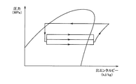
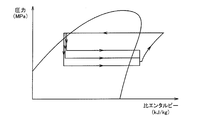
- FIG. 2 is a Mollier diagram showing the state of the refrigerant in the vapor compression refrigeration cycle 10.
- the horizontal axis in FIG. 2 indicates the specific enthalpy of the refrigerant, and the vertical axis indicates the absolute pressure of the refrigerant.
- the unit of specific enthalpy is kJ / kg, and the unit of absolute pressure is MPa.
- the curves in the figure are the saturated vapor line and saturated liquid line of the refrigerant.
- the refrigerant is sucked into the compressor 12 via the accumulator 60.
- the compressor 12 compresses the gas-phase refrigerant flowing from the accumulator 60.
- a receiver 62 is provided on the downstream side of the heat exchanger 14, and a refrigerant liquid in a supercooled liquid state is stored inside the receiver 62.
- the receiver 62 functions as a liquid reservoir that temporarily stores a refrigerant liquid that is a liquid refrigerant.
- a predetermined amount of refrigerant liquid is stored in the receiver 62, and the receiver 62 has a liquid storage function, so that it becomes a buffer against load fluctuation and absorbs load fluctuation. Therefore, since the flow rate of the refrigerant flowing to the cooling units 30 and 40 can be maintained even when the load changes, the cooling performance of the HV devices 31, 33, 41, and 43 can be stabilized.
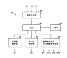
- the compressor control unit 85 receives the control command transmitted from the ECU 81, and transmits a signal C ⁇ b> 1 that instructs the start, stop, or rotation speed of the compressor 12 to the compressor 12.
- the motor control unit 86 receives the control command transmitted from the ECU 81, and transmits a signal M 1 for instructing the rotation speed of the motor 74 to the motor 74.
- the expansion valve and pressure regulating valve control unit 87 receives the control command transmitted from the ECU 81, transmits a signal RV1 for commanding the opening degree of the pressure regulating valve 19 to the pressure regulating valve 19, and sets the opening degree of the pressure regulating valve 39.
- a command signal RV 2 is transmitted to the pressure regulating valve 39, and a signal RV 3 that commands the opening degree of the pressure regulating valve 49 is transmitted to the pressure regulating valve 49.
- the pressure regulating valves 19, 39, and 49 are electric expansion valves that change the opening according to signals RV 1, RV 2, and RV 3 transmitted from the control unit 80.
- the expansion valve and pressure regulating valve control unit 87 also receives a control command transmitted from the ECU 81 and transmits a signal EV1 for commanding the opening degree of the expansion valve 16 to the expansion valve.
- the expansion valve 16 changes the opening according to the signal EV1 transmitted from the control unit 80.
- step (S20) it is determined whether or not the temperature of the refrigerant flowing through the cooling unit 30 exceeds the target temperature value. If it is determined in step (S20) that the temperature of the refrigerant exceeds the target value, then in step (S30), the opening of the pressure regulating valve 39 is increased. As the opening degree of the pressure regulating valve 39 is adjusted, the temperature of the refrigerant decreases in step (S40).
- the target value of the refrigerant temperature may be set as a specific value as a target value, or a specific temperature range having upper and lower limit values may be set as the target value.
- the refrigerant that cools the HV devices 31 and 33 in the cooling unit 30 flows into the cooling unit 30 in a gas-liquid two-phase state and is heated by heat exchange with the HV devices 31 and 33.
- the dryness increases, becoming dry saturated steam, and further becoming superheated steam.
- Most of the refrigerant flowing through the cooling passage 32 of the cooling unit 30 is in the state of wet vapor in a gas-liquid two-phase state.
- the temperature is low when the refrigerant pressure is low, and the temperature is high when the refrigerant pressure is high. That is, by increasing or decreasing the pressure of the gas-liquid two-phase refrigerant, the refrigerant temperature can be arbitrarily increased or decreased.
- step (S120) it is determined whether or not the degree of superheat of the refrigerant at the outlet of the cooling unit 30 exceeds the target value of the degree of superheat. If it is determined in step (S120) that the degree of superheat of the refrigerant exceeds the target value, then the opening degree of the control valve 37 is increased in step (S130). As the opening degree of the control valve 37 is adjusted, the flow rate of the refrigerant increases in step (S140).
- the target value of the superheat degree can be set so that, for example, the temperature difference between superheated steam and saturated steam under the same pressure is 3 to 5 ° C.
- the target value of superheat degree may set a specific superheat degree as a target value, and may set the range of the specific superheat degree which has an upper-lower limit value as a target value.
- the cooling device 1 that cools an electric device mounted on a vehicle has been described using the HV devices 31, 33, 41, and 43 as an example.
- the electric device is not limited to the exemplified electric device such as an inverter and a motor generator as long as it is an electric device that generates heat at least by operation, and may be any electric device.
- the target temperature range for cooling is a temperature range suitable as a temperature environment for operating the electrical equipment.
Landscapes
- Engineering & Computer Science (AREA)
- Physics & Mathematics (AREA)
- Mechanical Engineering (AREA)
- Thermal Sciences (AREA)
- General Engineering & Computer Science (AREA)
- Air-Conditioning For Vehicles (AREA)
Abstract
Provided is a cooling device in which it is possible to improve constancy in the performance of cooling heat-generating sources with a refrigerant. This cooling device (1) for cooling an HV instrument (31, 33) comprises: a compressor (12) that compresses a refrigerant; a heat exchanger (14) that exchanges heat between the refrigerant and outside air; an expansion valve (16) that decompresses the refrigerant; a heat exchanger (18) that exchanges heat between the refrigerant and air-conditioning air; a cooling part (30) that is connected in parallel to the heat exchanger (18) and that cools the HV instrument (31, 33) with the refrigerant; an expansion valve (19) that is provided on the downstream side of the heat exchanger (18) and that adjusts the pressure of the refrigerant flowing through the heat exchanger (18); and an expansion valve (39) that is provided on the downstream side of the cooling part (30) and that adjusts the pressure of the refrigerant flowing through the cooling part (30). The degree of opening of the expansion valve (19) is adjusted according to the temperature of the refrigerant between the expansion valve (16) and the expansion valve (19). The degree of opening of the expansion valve (39) is adjusted according to the temperature of the refrigerant between the expansion valve (16) and the expansion valve (39).
Description
本発明は、冷却装置に関し、特に、蒸気圧縮式冷凍サイクルを利用して発熱源を冷却する冷却装置に関する。
The present invention relates to a cooling device, and more particularly to a cooling device that cools a heat source using a vapor compression refrigeration cycle.
近年、環境問題対策の一つとして、モータの駆動力により走行するハイブリッド車、燃料電池車、電気自動車などが注目されている。このような車両において、モータ、ジェネレータ、インバータ、コンバータおよびバッテリなどの電気機器は、電力の授受によって発熱する。そのため、これらの電気機器を冷却する必要がある。そこで、車両用空調装置として使用される蒸気圧縮式冷凍サイクルを利用して、発熱体を冷却する技術が提案されている。
In recent years, attention has been focused on hybrid vehicles, fuel cell vehicles, electric vehicles, and the like that travel by the driving force of a motor as one of countermeasures for environmental problems. In such a vehicle, electric devices such as a motor, a generator, an inverter, a converter, and a battery generate heat when power is transferred. Therefore, it is necessary to cool these electric devices. In view of this, a technique for cooling a heating element using a vapor compression refrigeration cycle used as a vehicle air conditioner has been proposed.
たとえば特開2007-69733号公報(特許文献1)には、膨張弁から圧縮機へ至る冷媒通路に、空調用の空気と熱交換する熱交換器と、発熱体と熱交換する熱交換器と、を並列に配置し、空調装置用の冷媒を利用して発熱体を冷却するシステムが開示されている。
For example, Japanese Patent Laid-Open No. 2007-69733 (Patent Document 1) discloses a heat exchanger that exchanges heat with air for air conditioning, a heat exchanger that exchanges heat with a heating element, in a refrigerant passage from an expansion valve to a compressor. , Are arranged in parallel, and a system for cooling a heating element using a refrigerant for an air conditioner is disclosed.
特開平9-290622号公報(特許文献2)には、車両搭載の発熱部分からの廃熱を回収して、ガスインジェクション用の冷媒に吸熱させることにより、低外気温時における暖房能力を、消費電力の増大を抑制しつつ、効果的に向上する技術が開示されている。特開平11-23081号公報(特許文献3)には、冷凍サイクルの中間圧力の冷媒が発熱機器を冷却するように構成された冷却器と、この冷却器の上流側および下流側にそれぞれ配置され、外部信号により弁開度が制御可能な電気膨張弁を設け、中間圧力の冷媒で発熱機器の冷却を行なう装置が開示されている。
Japanese Patent Application Laid-Open No. 9-290622 (Patent Document 2) collects waste heat from a heat generating part mounted on a vehicle and absorbs heat in a refrigerant for gas injection, thereby consuming the heating capacity at a low outside temperature. A technique for effectively improving while suppressing an increase in electric power is disclosed. Japanese Patent Application Laid-Open No. 11-23081 (Patent Document 3) discloses a cooler configured such that an intermediate-pressure refrigerant in a refrigeration cycle cools a heat generating device, and an upstream side and a downstream side of the cooler. An apparatus is disclosed in which an electric expansion valve whose valve opening degree can be controlled by an external signal is provided, and a heat generating device is cooled with an intermediate-pressure refrigerant.
特開2001-309506号公報(特許文献4)には、車両走行モータを駆動制御するインバータ回路部の冷却部材に車両空調用冷凍サイクル装置の冷媒を還流させ、空調空気流の冷却が不要な場合に車両空調用冷凍サイクル装置のエバポレータによる空調空気流の冷却を抑止する、冷却システムが開示されている。特開2005-82066号公報(特許文献5)には、蒸発器に冷媒が滞留している場合に、圧縮機を作動させ蒸発器に滞留していた冷媒を回収した後に、車両のHV機器を始動させてポンプの運転を開始する、冷却システムが開示されている。
In Japanese Patent Laid-Open No. 2001-309506 (Patent Document 4), the refrigerant of the refrigeration cycle device for vehicle air conditioning is recirculated to the cooling member of the inverter circuit unit that drives and controls the vehicle running motor, and cooling of the air-conditioning air flow is unnecessary. Discloses a cooling system that suppresses cooling of an air-conditioned air flow by an evaporator of a vehicle air-conditioning refrigeration cycle apparatus. Japanese Patent Laid-Open No. 2005-82066 (Patent Document 5) discloses that when refrigerant stays in the evaporator, the compressor is operated to recover the refrigerant staying in the evaporator, and then the HV device of the vehicle is A cooling system is disclosed that is started to start operation of the pump.
車両用空調装置として使用される蒸気圧縮式冷凍サイクルでは、凝縮器において、車両の走行風としてまたはファンによる通風によって供給される外気と熱交換することにより、冷媒が冷却される。凝縮器に供給される外気の量が車両の走行状態によって変動することにより、凝縮器で冷却された後の冷媒の温度もまた変動する。加えて、冷却対象の発熱源の発熱量も車両の走行状態によって大きく変動する。そのため、冷媒による発熱源の冷却能力を一定に保つのは困難であった。
In the vapor compression refrigeration cycle used as a vehicle air conditioner, the refrigerant is cooled in the condenser by exchanging heat with the outside air supplied as the vehicle running air or by ventilation with a fan. As the amount of outside air supplied to the condenser varies depending on the running state of the vehicle, the temperature of the refrigerant after being cooled by the condenser also varies. In addition, the amount of heat generated by the heat source to be cooled varies greatly depending on the running state of the vehicle. For this reason, it has been difficult to keep the cooling capacity of the heat source by the refrigerant constant.
本発明は上記の課題に鑑みてなされたものであり、その主たる目的は、冷媒による発熱源の冷却能力の一定性を向上できる、冷却装置を提供することである。
The present invention has been made in view of the above-mentioned problems, and a main object thereof is to provide a cooling device that can improve the uniformity of the cooling capacity of the heat generation source by the refrigerant.
本発明に係る冷却装置は、発熱源を冷却する冷却装置であって、冷媒を圧縮する圧縮機と、冷媒と外気との間で熱交換する第一熱交換器と、冷媒を減圧する減圧器と、冷媒と空調用空気との間で熱交換する第二熱交換器と、第二熱交換器に並列に接続され、冷媒を用いて発熱源を冷却する冷却部と、第二熱交換器の下流側に設けられ、第二熱交換器を流れる冷媒の圧力を調節する第一圧力調整弁と、冷却部の下流側に設けられ、冷却部を流れる冷媒の圧力を調節する第二圧力調整弁と、を備える。第一圧力調整弁は、減圧器と第一圧力調整弁との間の冷媒の温度に従って開度を調整される。第二圧力調整弁は、減圧器と第二圧力調整弁との間の冷媒の温度に従って開度を調整される。
A cooling device according to the present invention is a cooling device that cools a heat generation source, a compressor that compresses a refrigerant, a first heat exchanger that exchanges heat between the refrigerant and outside air, and a decompressor that decompresses the refrigerant. A second heat exchanger that exchanges heat between the refrigerant and the air for air conditioning, a cooling unit that is connected in parallel to the second heat exchanger and that cools the heat source using the refrigerant, and a second heat exchanger A first pressure adjusting valve that adjusts the pressure of the refrigerant flowing through the second heat exchanger, and a second pressure adjustment that adjusts the pressure of the refrigerant flowing through the cooling section, downstream of the cooling section. And a valve. The opening degree of the first pressure regulating valve is adjusted according to the temperature of the refrigerant between the pressure reducer and the first pressure regulating valve. The opening of the second pressure regulating valve is adjusted according to the temperature of the refrigerant between the pressure reducer and the second pressure regulating valve.
上記冷却装置において好ましくは、第一圧力調整弁は、減圧器と第一圧力調整弁との間の冷媒の温度が設定値よりも高いとき弁開度を増大し、減圧器と第一圧力調整弁との間の冷媒の温度が設定値よりも低いとき弁開度を減少し、第二圧力調整弁は、減圧器と第二圧力調整弁との間の冷媒の温度が設定値よりも高いとき弁開度を増大し、減圧器と第二圧力調整弁との間の冷媒の温度が設定値よりも低いとき弁開度を減少する。
Preferably, in the above cooling device, the first pressure regulating valve increases the valve opening when the temperature of the refrigerant between the decompressor and the first pressure regulating valve is higher than a set value, and the decompressor and the first pressure regulating valve When the temperature of the refrigerant between the valves is lower than the set value, the valve opening is decreased, and the temperature of the refrigerant between the pressure reducer and the second pressure adjusting valve is higher than the set value in the second pressure regulating valve When the valve opening is increased, the valve opening is decreased when the temperature of the refrigerant between the pressure reducer and the second pressure regulating valve is lower than the set value.
上記冷却装置において好ましくは、圧縮機に吸入される冷媒を気液分離する気液分離器を備える。
Preferably, the cooling device includes a gas-liquid separator that gas-liquid separates the refrigerant sucked into the compressor.
上記冷却装置において好ましくは、減圧器は、第二熱交換器へ流入する冷媒の流量を調節する第一流量制御弁と、冷却部へ流入する冷媒の流量を調節する第二流量制御弁とを含む。
Preferably, in the cooling device, the decompressor includes a first flow control valve that adjusts a flow rate of the refrigerant flowing into the second heat exchanger, and a second flow rate control valve that adjusts the flow rate of the refrigerant flowing into the cooling unit. Including.
上記冷却装置において好ましくは、第一流量制御弁は、第二熱交換器の出口側の冷媒の過熱度に従って開度を調整され、第二流量制御弁は、冷却部の出口側の冷媒の過熱度に従って開度を調整される。
Preferably, in the cooling device, the opening degree of the first flow rate control valve is adjusted according to the degree of superheat of the refrigerant on the outlet side of the second heat exchanger, and the second flow rate control valve is configured to overheat the refrigerant on the outlet side of the cooling unit. The opening is adjusted according to the degree.
上記冷却装置において好ましくは、第一流量制御弁は、第二熱交換器の出口側の冷媒の過熱度が設定値よりも高いとき弁開度を増大し、第二熱交換器の出口側の冷媒の過熱度が設定値よりも低いとき弁開度を減少し、第二流量制御弁は、冷却部の出口側の冷媒の過熱度が設定値よりも高いとき弁開度を増大し、冷却部の出口側の冷媒の過熱度が設定値よりも低いとき弁開度を減少する。
Preferably, in the cooling device, the first flow control valve increases the valve opening when the degree of superheat of the refrigerant on the outlet side of the second heat exchanger is higher than a set value, and increases the valve opening degree on the outlet side of the second heat exchanger. When the degree of superheat of the refrigerant is lower than the set value, the valve opening is decreased, and the second flow rate control valve increases the valve opening when the degree of superheat of the refrigerant on the outlet side of the cooling unit is higher than the set value, thereby cooling When the degree of superheat of the refrigerant on the outlet side of the section is lower than the set value, the valve opening is decreased.
本発明の冷却装置によると、冷媒による発熱源の冷却能力の一定性を向上することができる。
According to the cooling device of the present invention, it is possible to improve the uniformity of the cooling capacity of the heat generation source by the refrigerant.
以下、図面に基づいてこの発明の実施の形態を説明する。なお、以下の図面において、同一または相当する部分には同一の参照番号を付し、その説明は繰返さない。
Hereinafter, embodiments of the present invention will be described with reference to the drawings. In the following drawings, the same or corresponding parts are denoted by the same reference numerals, and description thereof will not be repeated.
(実施の形態1)
図1は、実施の形態1の冷却装置1の構成を示す模式図である。本実施の形態に係る冷却装置1は、内燃機関であるエンジンと、電動機である駆動ユニットと、を動力源とするハイブリッド車両に適用され、ハイブリッド車両に搭載される電気機器の冷却に用いられる。なお、本発明の冷却装置1は、エンジンと電動機とを動力源とするハイブリッド車両のみならず、電動機のみを動力源とする車両(本明細書では、両者を包含して電気自動車という)にも適用可能である。 (Embodiment 1)
FIG. 1 is a schematic diagram illustrating a configuration of acooling device 1 according to the first embodiment. The cooling device 1 according to the present embodiment is applied to a hybrid vehicle that uses an engine that is an internal combustion engine and a drive unit that is an electric motor as power sources, and is used to cool an electric device mounted on the hybrid vehicle. Note that the cooling device 1 of the present invention is not limited to a hybrid vehicle that uses an engine and an electric motor as power sources, but also to a vehicle that uses only an electric motor as a power source (in this specification, both are referred to as an electric vehicle). Applicable.
図1は、実施の形態1の冷却装置1の構成を示す模式図である。本実施の形態に係る冷却装置1は、内燃機関であるエンジンと、電動機である駆動ユニットと、を動力源とするハイブリッド車両に適用され、ハイブリッド車両に搭載される電気機器の冷却に用いられる。なお、本発明の冷却装置1は、エンジンと電動機とを動力源とするハイブリッド車両のみならず、電動機のみを動力源とする車両(本明細書では、両者を包含して電気自動車という)にも適用可能である。 (Embodiment 1)
FIG. 1 is a schematic diagram illustrating a configuration of a
図1に示すように、冷却装置1は、蒸気圧縮式冷凍サイクル10を備える。蒸気圧縮式冷凍サイクル10は、たとえば、車両の車内の冷房を行なうために、車両に搭載される。蒸気圧縮式冷凍サイクル10を用いた冷房は、たとえば、冷房を行なうためのスイッチがオンされた場合、または、自動的に車両の室内の温度を設定温度になるように調整する自動制御モードが選択されており、かつ、車室内の温度が設定温度よりも高い場合に行なわれる。
As shown in FIG. 1, the cooling device 1 includes a vapor compression refrigeration cycle 10. The vapor compression refrigeration cycle 10 is mounted on a vehicle, for example, to cool the inside of the vehicle. The cooling using the vapor compression refrigeration cycle 10 is selected, for example, when the switch for performing the cooling is turned on or the automatic control mode for automatically adjusting the temperature of the vehicle interior to the set temperature is selected. This is performed when the temperature in the passenger compartment is higher than the set temperature.
蒸気圧縮式冷凍サイクル10は、圧縮機12と、第一熱交換器としての熱交換器14と、減圧器の一例としての膨張弁16と、第二熱交換器としての熱交換器18と、を含む。
The vapor compression refrigeration cycle 10 includes a compressor 12, a heat exchanger 14 as a first heat exchanger, an expansion valve 16 as an example of a decompressor, a heat exchanger 18 as a second heat exchanger, including.
圧縮機12は、車両に搭載されたモータまたはエンジンを動力源として作動し、冷媒ガスを断熱的に圧縮して過熱状態冷媒ガスとする。圧縮機12は、蒸気圧縮式冷凍サイクル10の作動時に熱交換器18から流通する冷媒を吸入圧縮して、冷媒通路21に高温高圧の気相冷媒を吐出する。圧縮機12は、冷媒通路21に冷媒を吐出することで、蒸気圧縮式冷凍サイクル10に冷媒を循環させる。
The compressor 12 operates with a motor or engine mounted on the vehicle as a power source, and compresses the refrigerant gas in an adiabatic manner to form an overheated refrigerant gas. The compressor 12 sucks and compresses the refrigerant flowing from the heat exchanger 18 when the vapor compression refrigeration cycle 10 is operated, and discharges a high-temperature and high-pressure gas-phase refrigerant into the refrigerant passage 21. The compressor 12 circulates the refrigerant in the vapor compression refrigeration cycle 10 by discharging the refrigerant into the refrigerant passage 21.
熱交換器14は、圧縮機12において圧縮された過熱状態冷媒ガスを、外部媒体へ等圧的に放熱させて冷媒液とする。圧縮機12から吐出された高圧の気相冷媒は、熱交換器14において周囲に放熱し冷却されることによって、凝縮(液化)する。熱交換器14は、冷媒を流通するチューブと、チューブ内を流通する冷媒と熱交換器14の周囲の空気との間で熱交換するためのフィンと、を含む。
The heat exchanger 14 dissipates the superheated refrigerant gas compressed in the compressor 12 isothermally to an external medium to obtain a refrigerant liquid. The high-pressure gas-phase refrigerant discharged from the compressor 12 is condensed (liquefied) by releasing heat to the surroundings and cooling in the heat exchanger 14. The heat exchanger 14 includes a tube through which the refrigerant flows, and fins for exchanging heat between the refrigerant flowing through the tube and the air around the heat exchanger 14.
熱交換器14は、冷却風と冷媒との間で、熱交換を行なう。冷却風は、車両の走行によって発生する自然の通風によって熱交換器14に供給されてもよい。または冷却風は、コンデンサファン72もしくはエンジン冷却用のラジエータファンなどの、外気供給用ファンからの強制通風によって熱交換器14に供給されてもよい。熱交換器14における外気との熱交換によって、冷媒の温度は低下し冷媒は液化する。
The heat exchanger 14 performs heat exchange between the cooling air and the refrigerant. The cooling air may be supplied to the heat exchanger 14 by natural ventilation generated by traveling of the vehicle. Alternatively, the cooling air may be supplied to the heat exchanger 14 by forced ventilation from an external air supply fan such as the condenser fan 72 or a radiator fan for cooling the engine. By the heat exchange with the outside air in the heat exchanger 14, the temperature of the refrigerant is lowered and the refrigerant is liquefied.
膨張弁16は、冷媒通路25を流通する高圧の液相冷媒を小さな孔から噴射させることにより膨張させて、低温・低圧の霧状冷媒に変化させる。膨張弁16は、熱交換器14によって凝縮された冷媒液を減圧して、気液混合状態の湿り蒸気とする。なお、冷媒液を減圧するための減圧器は、絞り膨張する膨張弁16に限られず、毛細管または開度制御可能な制御弁であってもよい。
The expansion valve 16 expands by injecting a high-pressure liquid refrigerant flowing through the refrigerant passage 25 from a small hole, and changes the low-temperature / low-pressure mist refrigerant. The expansion valve 16 depressurizes the refrigerant liquid condensed by the heat exchanger 14 to obtain wet vapor in a gas-liquid mixed state. Note that the decompressor for decompressing the refrigerant liquid is not limited to the expansion valve 16 that is throttled and expanded, and may be a capillary tube or a control valve capable of controlling the opening degree.
熱交換器18は、冷媒と空調用空気との間で熱交換して、空調用空気の温度を調節する。熱交換器18は、その内部を流通する霧状冷媒が気化することによって、熱交換器18に接触するように導入された周囲の空気の熱を吸収する。図示しない空調用ファンが駆動することにより、熱交換器18に空調用空気が供給される。空調用空気は、外気であってもよく、車両の室内の空気であってもよい。
The heat exchanger 18 exchanges heat between the refrigerant and the air-conditioning air to adjust the temperature of the air-conditioning air. The heat exchanger 18 absorbs heat of ambient air introduced so as to come into contact with the heat exchanger 18 by vaporizing the mist refrigerant flowing through the heat exchanger 18. Air conditioning air is supplied to the heat exchanger 18 by driving an air conditioning fan (not shown). The air for air conditioning may be outside air or air in the vehicle interior.
冷房運転時には、熱交換器18は、膨張弁16によって減圧された冷媒を用いて、冷媒の湿り蒸気が蒸発して冷媒ガスとなる際の気化熱を、車両の室内へ流通する空調用空気から吸収して、車両の室内の冷房を行なう。熱が熱交換器18に吸収されることによって温度が低下した空調用空気が車両の室内に再び戻されることによって、車両の室内の冷房が行なわれる。熱交換器18において空調用空気が冷却され、熱交換器18において冷媒は空調用空気からの熱伝達を受けて周囲から吸熱し加熱される。
During the cooling operation, the heat exchanger 18 uses the refrigerant depressurized by the expansion valve 16, and the heat of vaporization when the vapor of the refrigerant evaporates to become refrigerant gas from the air-conditioning air flowing into the vehicle interior. Absorbs and cools the interior of the vehicle. The air-conditioning air whose temperature has been reduced by the heat being absorbed by the heat exchanger 18 is returned again to the vehicle interior, thereby cooling the vehicle interior. In the heat exchanger 18, the air for air conditioning is cooled, and in the heat exchanger 18, the refrigerant receives heat transfer from the air for air conditioning and absorbs heat from the surroundings to be heated.
熱交換器18は、冷媒を流通するチューブと、チューブ内を流通する冷媒と熱交換器18の周囲の空気との間で熱交換するためのフィンと、を含む。チューブ内には、湿り蒸気状態の冷媒が流入する。冷媒は、チューブ内を流通する際に、フィンを経由して車両の室内の空気の熱を蒸発潜熱として吸収することによって蒸発し、さらに顕熱によって過熱蒸気になる。気化した冷媒は、圧縮機12へ吸入される。圧縮機12は、熱交換器18から流通する過熱蒸気状態の冷媒を圧縮する。
The heat exchanger 18 includes a tube through which the refrigerant flows, and fins for exchanging heat between the refrigerant flowing through the tube and the air around the heat exchanger 18. A wet steam refrigerant flows into the tube. When the refrigerant circulates in the tube, it evaporates by absorbing the heat of the air in the vehicle interior as latent heat of evaporation via the fins, and further becomes superheated steam by sensible heat. The vaporized refrigerant is sucked into the compressor 12. The compressor 12 compresses the superheated steam refrigerant flowing from the heat exchanger 18.
蒸気圧縮式冷凍サイクル10はまた、圧縮機12と熱交換器14とを連通する冷媒通路21と、熱交換器14と膨張弁16とを連通する冷媒通路22,23と、膨張弁16と熱交換器18とを連通する冷媒通路24と、熱交換器18と圧縮機12とを連通する冷媒通路25,26,27と、を含む。
The vapor compression refrigeration cycle 10 also includes a refrigerant passage 21 that communicates the compressor 12 and the heat exchanger 14, refrigerant passages 22 and 23 that communicate the heat exchanger 14 and the expansion valve 16, the expansion valve 16 and the heat. A refrigerant passage 24 that communicates with the exchanger 18 and refrigerant passages 25, 26, and 27 that communicate between the heat exchanger 18 and the compressor 12 are included.
冷媒通路21は、冷媒を圧縮機12から熱交換器14に流通させるための通路である。冷媒は、冷媒通路21を経由して、圧縮機12と熱交換器14との間を、圧縮機12の出口から熱交換器14の入口へ向かって流れる。冷媒通路22,23は、冷媒を熱交換器14から膨張弁16に流通させるための通路である。冷媒は、冷媒通路22,23を経由して、熱交換器14と膨張弁16との間を、熱交換器14の出口から膨張弁16の入口へ向かって流れる。
The refrigerant passage 21 is a passage for circulating the refrigerant from the compressor 12 to the heat exchanger 14. The refrigerant flows between the compressor 12 and the heat exchanger 14 from the outlet of the compressor 12 toward the inlet of the heat exchanger 14 via the refrigerant passage 21. The refrigerant passages 22 and 23 are passages for circulating the refrigerant from the heat exchanger 14 to the expansion valve 16. The refrigerant flows between the heat exchanger 14 and the expansion valve 16 from the outlet of the heat exchanger 14 toward the inlet of the expansion valve 16 via the refrigerant passages 22 and 23.
冷媒通路24は、冷媒を膨張弁16から熱交換器18に流通させるための通路である。冷媒は、冷媒通路24を経由して、膨張弁16と熱交換器18との間を、膨張弁16の出口から熱交換器18の入口へ向かって流れる。冷媒通路25~27は、冷媒を熱交換器18から圧縮機12に流通させるための通路である。冷媒は、冷媒通路25~27を経由して、熱交換器18と圧縮機12との間を、熱交換器18の出口から圧縮機12の入口へ向かって流れる。
The refrigerant passage 24 is a passage for circulating the refrigerant from the expansion valve 16 to the heat exchanger 18. The refrigerant flows between the expansion valve 16 and the heat exchanger 18 from the outlet of the expansion valve 16 toward the inlet of the heat exchanger 18 via the refrigerant passage 24. The refrigerant passages 25 to 27 are passages for circulating the refrigerant from the heat exchanger 18 to the compressor 12. The refrigerant flows between the heat exchanger 18 and the compressor 12 from the outlet of the heat exchanger 18 toward the inlet of the compressor 12 via the refrigerant passages 25 to 27.
蒸気圧縮式冷凍サイクル10は、圧縮機12、熱交換器14、膨張弁16および熱交換器18が、冷媒通路21~27によって連結されて構成される。なお、蒸気圧縮式冷凍サイクル10の冷媒としては、たとえば二酸化炭素、プロパンやイソブタンなどの炭化水素、アンモニア、フロン類または水などを用いることができる。
The vapor compression refrigeration cycle 10 includes a compressor 12, a heat exchanger 14, an expansion valve 16, and a heat exchanger 18 connected by refrigerant passages 21 to 27. As the refrigerant of the vapor compression refrigeration cycle 10, for example, carbon dioxide, hydrocarbons such as propane and isobutane, ammonia, chlorofluorocarbons or water can be used.
熱交換器18と圧縮機12との間の冷媒の経路上には、アキュムレータ60が配置されている。アキュムレータ60は、熱交換器18から流出する冷媒を気相冷媒と液相冷媒とに分離する。アキュムレータ60の内部には、液相冷媒である冷媒液と、気相冷媒である冷媒蒸気と、が蓄蔵可能である。アキュムレータ60には、冷媒通路26と、冷媒通路27とが連結されている。
An accumulator 60 is disposed on the refrigerant path between the heat exchanger 18 and the compressor 12. The accumulator 60 separates the refrigerant flowing out from the heat exchanger 18 into a gas phase refrigerant and a liquid phase refrigerant. Inside the accumulator 60, a refrigerant liquid that is a liquid phase refrigerant and a refrigerant vapor that is a gas phase refrigerant can be stored. A refrigerant passage 26 and a refrigerant passage 27 are connected to the accumulator 60.
熱交換器18から流出した冷媒は、冷媒通路25,26を通ってアキュムレータ60へ供給される。冷媒通路26からアキュムレータ60へ流入する冷媒は、アキュムレータ60の内部において気相と液相とに分離される。熱交換器18または後述する冷却部30,40で全ての冷媒が蒸発せず、アキュムレータ60へ流入する冷媒が気液二相状態である場合、アキュムレータ60は、冷媒を液体状の冷媒液とガス状の冷媒蒸気とに分離して、一時的に蓄える。気液分離された冷媒蒸気は、冷媒通路27を経由して、アキュムレータ60の外部へ流出し、圧縮機12へ吸入される。
The refrigerant that has flowed out of the heat exchanger 18 is supplied to the accumulator 60 through the refrigerant passages 25 and 26. The refrigerant flowing into the accumulator 60 from the refrigerant passage 26 is separated into a gas phase and a liquid phase inside the accumulator 60. When all the refrigerant does not evaporate in the heat exchanger 18 or the cooling units 30 and 40 described later and the refrigerant flowing into the accumulator 60 is in a gas-liquid two-phase state, the accumulator 60 converts the refrigerant into a liquid refrigerant liquid and a gas. The refrigerant vapor is separated and temporarily stored. The gas-liquid separated refrigerant vapor flows out of the accumulator 60 through the refrigerant passage 27 and is sucked into the compressor 12.
アキュムレータ60の気相側に連結された冷媒通路27の端部は、アキュムレータ60からの気相冷媒の流出口を形成する。アキュムレータ60の内部では、冷媒液が下側、冷媒蒸気が上側に溜まる。アキュムレータ60から冷媒蒸気を導出する冷媒通路27の端部は、アキュムレータ60の天井部に連結されている。冷媒通路27を経由して、アキュムレータ60の天井側から冷媒蒸気のみがアキュムレータ60の外部へ送り出される。これにより、アキュムレータ60は、気相冷媒と液相冷媒とを確実に分離できる。
The end of the refrigerant passage 27 connected to the gas phase side of the accumulator 60 forms an outlet for the gas phase refrigerant from the accumulator 60. Inside the accumulator 60, refrigerant liquid accumulates on the lower side and refrigerant vapor accumulates on the upper side. An end portion of the refrigerant passage 27 for leading the refrigerant vapor from the accumulator 60 is connected to a ceiling portion of the accumulator 60. Only the refrigerant vapor is sent out of the accumulator 60 from the ceiling side of the accumulator 60 via the refrigerant passage 27. Thereby, the accumulator 60 can reliably separate the gas-phase refrigerant and the liquid-phase refrigerant.
熱交換器18とアキュムレータ60との間には、圧力調整弁19が設けられている。冷媒通路25は、熱交換器18と圧力調整弁19との間の冷媒の経路を形成する。冷媒通路26は、圧力調整弁19とアキュムレータ60との間の冷媒の経路を形成する。圧力調整弁19は、熱交換器18の下流側に設けられた、上述した減圧器としての膨張弁16とは異なる弁である。圧力調整弁19は、熱交換器18を流れる冷媒の圧力を調節する第一圧力調整弁としての機能を有する。
A pressure regulating valve 19 is provided between the heat exchanger 18 and the accumulator 60. The refrigerant passage 25 forms a refrigerant path between the heat exchanger 18 and the pressure regulating valve 19. The refrigerant passage 26 forms a refrigerant path between the pressure regulating valve 19 and the accumulator 60. The pressure regulating valve 19 is a valve that is provided on the downstream side of the heat exchanger 18 and is different from the expansion valve 16 as a pressure reducer described above. The pressure regulating valve 19 has a function as a first pressure regulating valve that regulates the pressure of the refrigerant flowing through the heat exchanger 18.
圧力調整弁19の開度を増大すると、圧力調整弁19を通過する冷媒の圧力損失が相対的に小さくなり、冷媒通路25を流れる冷媒と冷媒通路26を流れる冷媒との圧力差が小さくなる。そのため、熱交換器18を流れる冷媒の圧力は、圧縮機12に吸入される冷媒の圧力に近づく。圧力調整弁19の開度が大きいとき、熱交換器18を流れる冷媒の圧力は相対的に低くなる。圧力調整弁19の開度を調整し、圧力調整弁19の開度が増大するように圧力調整弁19を制御することにより、熱交換器18を流れる冷媒の圧力を下げることができる。
When the opening of the pressure regulating valve 19 is increased, the pressure loss of the refrigerant passing through the pressure regulating valve 19 becomes relatively small, and the pressure difference between the refrigerant flowing through the refrigerant passage 25 and the refrigerant flowing through the refrigerant passage 26 becomes small. Therefore, the pressure of the refrigerant flowing through the heat exchanger 18 approaches the pressure of the refrigerant sucked into the compressor 12. When the opening of the pressure regulating valve 19 is large, the pressure of the refrigerant flowing through the heat exchanger 18 is relatively low. By adjusting the opening of the pressure adjusting valve 19 and controlling the pressure adjusting valve 19 so that the opening of the pressure adjusting valve 19 increases, the pressure of the refrigerant flowing through the heat exchanger 18 can be lowered.
圧力調整弁19の開度を減少すると、圧力調整弁19を通過する冷媒の圧力損失が相対的に大きくなり、冷媒通路25を流れる冷媒と冷媒通路26を流れる冷媒との圧力差が大きくなる。そのため、熱交換器18を流れる冷媒の圧力は、圧縮機12に吸入される冷媒の圧力から離れる。圧力調整弁19の開度が小さいとき、熱交換器18を流れる冷媒の圧力は相対的に高くなる。圧力調整弁19の開度を調整し、圧力調整弁19の開度が減少するように圧力調整弁19を制御することにより、熱交換器18を流れる冷媒の圧力を高めることができる。
When the opening degree of the pressure regulating valve 19 is decreased, the pressure loss of the refrigerant passing through the pressure regulating valve 19 becomes relatively large, and the pressure difference between the refrigerant flowing through the refrigerant passage 25 and the refrigerant flowing through the refrigerant passage 26 increases. Therefore, the pressure of the refrigerant flowing through the heat exchanger 18 is separated from the pressure of the refrigerant sucked into the compressor 12. When the opening of the pressure regulating valve 19 is small, the pressure of the refrigerant flowing through the heat exchanger 18 becomes relatively high. The pressure of the refrigerant flowing through the heat exchanger 18 can be increased by adjusting the opening of the pressure adjusting valve 19 and controlling the pressure adjusting valve 19 so that the opening of the pressure adjusting valve 19 decreases.
冷媒通路25には、熱交換器18から流出して冷媒通路25を流れる冷媒の温度を検出する、温度検出部52が設けられている。温度検出部52によって検出された冷媒の温度に基づいて、圧力調整弁19は、その開度を制御される。具体的には、冷媒通路25を流れる冷媒の温度が目標値よりも高いとき、圧力調整弁19の開度を増大し、冷媒通路25を流れる冷媒の温度が目標値よりも低いとき、圧力調整弁19の開度を減少する。
The refrigerant passage 25 is provided with a temperature detection unit 52 that detects the temperature of the refrigerant that flows out of the heat exchanger 18 and flows through the refrigerant passage 25. Based on the temperature of the refrigerant detected by the temperature detector 52, the opening degree of the pressure regulating valve 19 is controlled. Specifically, when the temperature of the refrigerant flowing through the refrigerant passage 25 is higher than the target value, the opening degree of the pressure adjustment valve 19 is increased, and when the temperature of the refrigerant flowing through the refrigerant passage 25 is lower than the target value, the pressure adjustment is performed. The opening degree of the valve 19 is decreased.
蒸気圧縮式冷凍サイクル10はまた、熱交換器14と膨張弁16との間の冷媒の経路上に配置されたレシーバ62を含む。レシーバ62は、熱交換器14から流出する冷媒を気相冷媒と液相冷媒とに分離する。レシーバ62の内部には、液相冷媒である冷媒液と、気相冷媒である冷媒蒸気と、が蓄蔵可能である。レシーバ62には、冷媒通路22と、冷媒通路23とが連結されている。
The vapor compression refrigeration cycle 10 also includes a receiver 62 disposed on the refrigerant path between the heat exchanger 14 and the expansion valve 16. The receiver 62 separates the refrigerant flowing out of the heat exchanger 14 into a gas phase refrigerant and a liquid phase refrigerant. Inside the receiver 62, a refrigerant liquid that is a liquid phase refrigerant and a refrigerant vapor that is a gas phase refrigerant can be stored. The refrigerant passage 22 and the refrigerant passage 23 are connected to the receiver 62.
熱交換器14から流出した冷媒は、冷媒通路22を通ってレシーバ62へ供給される。冷媒通路22からレシーバ62へ流入する冷媒は、レシーバ62の内部において気相と液相とに分離される。熱交換器14で全ての冷媒が凝縮せず、レシーバ62へ流入する冷媒が気液二相状態である場合、レシーバ62は、冷媒を液体状の冷媒液とガス状の冷媒蒸気とに分離して、一時的に蓄える。気液分離された冷媒液は、冷媒通路23を経由して、レシーバ62の外部へ流出する。
The refrigerant that has flowed out of the heat exchanger 14 is supplied to the receiver 62 through the refrigerant passage 22. The refrigerant flowing into the receiver 62 from the refrigerant passage 22 is separated into a gas phase and a liquid phase inside the receiver 62. When not all the refrigerant is condensed in the heat exchanger 14 and the refrigerant flowing into the receiver 62 is in a gas-liquid two-phase state, the receiver 62 separates the refrigerant into a liquid refrigerant liquid and a gaseous refrigerant vapor. And store temporarily. The gas-liquid separated refrigerant liquid flows out of the receiver 62 via the refrigerant passage 23.
レシーバ62の液相側に連結された冷媒通路23の端部は、レシーバ62からの液相冷媒の流出口を形成する。レシーバ62の内部では、冷媒液が下側、冷媒蒸気が上側に溜まる。レシーバ62から冷媒液を導出する冷媒通路23の端部は、レシーバ62の底部に連結されている。冷媒通路23を経由して、レシーバ62の底側から冷媒液のみがレシーバ62の外部へ送り出される。これにより、レシーバ62は、気相冷媒と液相冷媒とを確実に分離できる。
The end of the refrigerant passage 23 connected to the liquid phase side of the receiver 62 forms an outlet for the liquid phase refrigerant from the receiver 62. Inside the receiver 62, the refrigerant liquid accumulates on the lower side and the refrigerant vapor accumulates on the upper side. An end portion of the refrigerant passage 23 for leading the refrigerant liquid from the receiver 62 is connected to the bottom portion of the receiver 62. Only the refrigerant liquid is sent out of the receiver 62 from the bottom side of the receiver 62 via the refrigerant passage 23. Thereby, the receiver 62 can reliably separate the gas-phase refrigerant and the liquid-phase refrigerant.
膨張弁16からアキュムレータ60へ向けて流れる冷媒の経路上には、熱交換器18と並列に接続された、冷却部30,40が設けられている。冷却装置1は、熱交換器18と並列に接続された冷媒の経路を備え、冷却部30,40は、当該冷媒の経路上に設けられている。膨張弁16とアキュムレータ60との間を流れる冷媒の経路において並列に接続された複数の通路のうちの一つに熱交換器18が設けられ、当該複数の経路のうちの他の一つに冷却部30が設けられ、当該複数の通路のうちのさらに他の一つに冷却部40が設けられている。
Cooling units 30 and 40 connected in parallel with the heat exchanger 18 are provided on the path of the refrigerant flowing from the expansion valve 16 toward the accumulator 60. The cooling device 1 includes a refrigerant path connected in parallel with the heat exchanger 18, and the cooling units 30 and 40 are provided on the refrigerant path. The heat exchanger 18 is provided in one of a plurality of passages connected in parallel in the path of the refrigerant flowing between the expansion valve 16 and the accumulator 60, and the other one of the plurality of paths is cooled. The part 30 is provided, and the cooling part 40 is provided in yet another one of the plurality of passages.
膨張弁16と熱交換器18との間の冷媒通路24から、冷媒通路34,44が分岐している。冷媒通路34は、冷媒通路24と冷却部30とを連通する。冷媒は、冷媒通路24から、冷媒通路34を経由して、冷却部30へ流れる。冷媒通路44は、冷媒通路24と冷却部40とを連通する。冷媒は、冷媒通路24から、冷媒通路44を経由して、冷却部40へ流れる。
The refrigerant passages 34 and 44 are branched from the refrigerant passage 24 between the expansion valve 16 and the heat exchanger 18. The refrigerant passage 34 communicates the refrigerant passage 24 and the cooling unit 30. The refrigerant flows from the refrigerant passage 24 to the cooling unit 30 via the refrigerant passage 34. The refrigerant passage 44 communicates the refrigerant passage 24 and the cooling unit 40. The refrigerant flows from the refrigerant passage 24 to the cooling unit 40 via the refrigerant passage 44.
冷却部30は、電気自動車に搭載される電気機器であるHV(Hybrid Vehicle)機器31,33と、冷媒が流通する配管である冷却通路32とを含む。冷却部40は、電気自動車に搭載される電気機器であるHV機器41,43と、冷媒が流通する配管である冷却通路42とを含む。HV機器31,33,41,43は、電力の授受によって発熱する発熱源の一例である。
The cooling unit 30 includes HV (Hybrid Vehicle) devices 31 and 33 that are electric devices mounted on an electric vehicle, and a cooling passage 32 that is a pipe through which a refrigerant flows. The cooling unit 40 includes HV devices 41 and 43 that are electric devices mounted on an electric vehicle, and a cooling passage 42 that is a pipe through which a refrigerant flows. The HV devices 31, 33, 41, and 43 are examples of heat generation sources that generate heat when power is transferred.
HV機器31,33,41,43は、たとえば、直流電力を交流電力に変換するためのインバータ、回転電機であるモータジェネレータ、蓄電装置であるバッテリ、バッテリの電圧を昇圧させるための昇圧コンバータ、バッテリの電圧を降圧するためのDC/DCコンバータなどの、少なくともいずれか一つを含む。バッテリは、リチウムイオン電池あるいはニッケル水素電池等の二次電池である。バッテリに代えてキャパシタが用いられてもよい。たとえば、HV機器31およびHV機器33はインバータであり、HV機器41はバッテリであり、HV機器43はキャパシタであってもよい。
The HV devices 31, 33, 41, 43 include, for example, an inverter for converting DC power to AC power, a motor generator that is a rotating electrical machine, a battery that is a power storage device, a boost converter that boosts the voltage of the battery, and a battery. Including at least one of a DC / DC converter and the like for stepping down the voltage. The battery is a secondary battery such as a lithium ion battery or a nickel metal hydride battery. A capacitor may be used instead of the battery. For example, the HV device 31 and the HV device 33 may be inverters, the HV device 41 may be a battery, and the HV device 43 may be a capacitor.
レシーバ62から流出した冷媒液は、冷媒通路34を経由して冷却部30へ向かって流れ、冷媒通路44を経由して冷却部40へ向かって流れる。冷却部30,40へ到達し、冷却通路32,42を経由して流れる冷媒は、発熱源としてのHV機器31,33,41,43の各々から熱を奪って冷却させる。冷却部30,40は、レシーバ62において分離された液相の冷媒を用いて、HV機器31,33,41,43を冷却する。冷却部30,40において、冷却通路32内を流通する冷媒とHV機器31,33とが熱交換し、冷却通路42内を流通する冷媒とHV機器41,43とが熱交換することにより、HV機器31,33,41,43は冷却され、冷媒は加熱される。
The refrigerant liquid flowing out from the receiver 62 flows toward the cooling unit 30 via the refrigerant passage 34 and flows toward the cooling unit 40 via the refrigerant passage 44. The refrigerant that reaches the cooling units 30 and 40 and flows through the cooling passages 32 and 42 cools the refrigerant by taking heat from each of the HV devices 31, 33, 41, and 43 as heat generation sources. The cooling units 30 and 40 cool the HV devices 31, 33, 41, and 43 using the liquid-phase refrigerant separated in the receiver 62. In the cooling units 30 and 40, the refrigerant flowing in the cooling passage 32 and the HV devices 31 and 33 exchange heat, and the refrigerant flowing in the cooling passage 42 and the HV devices 41 and 43 exchange heat, so that the HV The devices 31, 33, 41, and 43 are cooled and the refrigerant is heated.
冷却部30,40は、冷却通路32,42においてHV機器31,33,41,43と冷媒との間で熱交換が可能な構造を有するように設けられる。本実施の形態においては、冷却部30,40は、たとえば、HV機器31,33,41,43の筐体に冷却通路32,42の外周面が直接接触するように形成された冷却通路32,42を有する。冷却通路32,42は、HV機器31,33,41,43の筐体と隣接する部分を有する。当該部分において、冷却通路32,42を流通する冷媒と、HV機器31,33,41,43との間で、熱交換が可能となる。
The cooling units 30 and 40 are provided so as to have a structure capable of exchanging heat between the HV devices 31, 33, 41 and 43 and the refrigerant in the cooling passages 32 and 42. In the present embodiment, the cooling units 30 and 40 include, for example, cooling passages 32 and 42 formed so that the outer peripheral surfaces of the cooling passages 32 and 42 are in direct contact with the housings of the HV devices 31, 33, 41, and 43. 42. The cooling passages 32 and 42 have portions adjacent to the housings of the HV devices 31, 33, 41, and 43. In this portion, heat exchange can be performed between the refrigerant flowing through the cooling passages 32 and 42 and the HV devices 31, 33, 41, and 43.
HV機器31,33,41,43は、蒸気圧縮式冷凍サイクル10の膨張弁16からアキュムレータ60に至る冷媒の経路の一部を形成する冷却通路32,42の外周面に直接接続されて、冷却される。冷却通路32,42の外部にHV機器31,33,41,43が配置されるので、冷却通路32,42の内部を流通する冷媒の流れにHV機器31,33,41,43が干渉することはない。そのため、蒸気圧縮式冷凍サイクル10の圧力損失は増大しないので、圧縮機12の動力を増大させることなく、HV機器31,33,41,43を冷却することができる。
The HV devices 31, 33, 41, and 43 are directly connected to the outer peripheral surfaces of the cooling passages 32 and 42 that form part of the refrigerant path from the expansion valve 16 to the accumulator 60 of the vapor compression refrigeration cycle 10, Is done. Since the HV devices 31, 33, 41, 43 are disposed outside the cooling passages 32, 42, the HV devices 31, 33, 41, 43 interfere with the flow of the refrigerant flowing through the cooling passages 32, 42. There is no. Therefore, since the pressure loss of the vapor compression refrigeration cycle 10 does not increase, the HV equipment 31, 33, 41, 43 can be cooled without increasing the power of the compressor 12.
代替的には、冷却部30,40は、HV機器31,33,41,43と冷却通路32,42との間に介在して配置された任意の公知のヒートパイプを備えてもよい。この場合HV機器31,33,41,43は、冷却通路32,42の外周面にヒートパイプを介して接続され、HV機器31,33,41,43から冷却通路32,42へヒートパイプを経由して熱伝達することにより、冷却される。HV機器31,33,41,43をヒートパイプの加熱部とし冷却通路32,42をヒートパイプの冷却部とすることで、冷却通路32,42とHV機器31,33,41,43との間の熱伝達効率が高められるので、HV機器31,33,41,43の冷却効率を向上できる。たとえばウィック式のヒートパイプを使用することができる。
Alternatively, the cooling units 30 and 40 may include any known heat pipes disposed between the HV devices 31, 33, 41 and 43 and the cooling passages 32 and 42. In this case, the HV devices 31, 33, 41, 43 are connected to the outer peripheral surfaces of the cooling passages 32, 42 via heat pipes, and pass from the HV devices 31, 33, 41, 43 to the cooling passages 32, 42 via the heat pipes. Then, it is cooled by transferring heat. By using the HV equipment 31, 33, 41, 43 as the heat pipe heating section and the cooling passages 32, 42 as the heat pipe cooling section, between the cooling passages 32, 42 and the HV equipment 31, 33, 41, 43. Therefore, the cooling efficiency of the HV equipment 31, 33, 41, 43 can be improved. For example, a wick-type heat pipe can be used.
ヒートパイプによってHV機器31,33,41,43から冷却通路32,42へ確実に熱伝達することができるので、HV機器31,33,41,43と冷却通路32,42との間に距離があってもよく、HV機器31,33,41,43に冷却通路32,42を接触させるために冷却通路32,42を複雑に配置する必要がない。その結果、HV機器31,33,41,43の配置の自由度を向上することができる。
Since heat can be reliably transferred from the HV equipment 31, 33, 41, 43 to the cooling passages 32, 42 by the heat pipe, there is a distance between the HV equipment 31, 33, 41, 43 and the cooling passages 32, 42. The cooling passages 32 and 42 need not be arranged in a complicated manner in order to bring the cooling passages 32 and 42 into contact with the HV devices 31, 33, 41 and 43. As a result, the degree of freedom of arrangement of the HV devices 31, 33, 41, 43 can be improved.
冷却部30においてHV機器31,33を冷却することによりHV機器31,33と熱交換して加熱された冷媒は、冷媒通路35,36を経由して、冷媒通路26へ戻る。熱交換器18を経由して流れる冷媒の経路に対し並列に接続された冷媒の経路は、冷却部30よりも上流側(膨張弁16に近接する側)の冷媒通路34と、冷却部30に含まれる冷却通路32と、冷却部30よりも下流側(アキュムレータ60に近接する側)の冷媒通路35,36と、を含む。冷却部30には、冷媒通路34,35が接続されている。冷却通路32の一方の端部は、冷媒通路34に接続される。冷却通路32の他方の端部は、冷媒通路35に接続される。
The refrigerant heated by exchanging heat with the HV devices 31 and 33 by cooling the HV devices 31 and 33 in the cooling unit 30 returns to the refrigerant passage 26 via the refrigerant passages 35 and 36. The refrigerant path connected in parallel to the refrigerant path flowing via the heat exchanger 18 is connected to the refrigerant passage 34 upstream of the cooling unit 30 (the side close to the expansion valve 16) and the cooling unit 30. The cooling passage 32 included, and refrigerant passages 35 and 36 on the downstream side (the side closer to the accumulator 60) than the cooling unit 30 are included. Refrigerant passages 34 and 35 are connected to the cooling unit 30. One end of the cooling passage 32 is connected to the refrigerant passage 34. The other end of the cooling passage 32 is connected to the refrigerant passage 35.
冷媒通路34は、冷媒通路24と冷却部30とを連通し、膨張弁16で冷却された冷媒を冷却部30に流通させるための通路である。冷媒通路34を経由して、冷媒通路24から冷却部30へ冷媒液が流れる。冷媒通路35,36は、冷却部30と冷媒通路26とを連通し、冷却部30から冷媒通路26に冷媒を流通させるための通路である。冷却部30を通過した冷媒は、冷媒通路35,36を経由して、冷媒通路26へ戻り、冷媒通路26を経由してアキュムレータ60へ至る。
The refrigerant passage 34 is a passage through which the refrigerant passage 24 and the cooling unit 30 are communicated and the refrigerant cooled by the expansion valve 16 is circulated to the cooling unit 30. The refrigerant liquid flows from the refrigerant passage 24 to the cooling unit 30 via the refrigerant passage 34. The refrigerant passages 35 and 36 are passages that allow the cooling unit 30 and the refrigerant passage 26 to communicate with each other and allow the refrigerant to flow from the cooling unit 30 to the refrigerant passage 26. The refrigerant that has passed through the cooling unit 30 returns to the refrigerant passage 26 via the refrigerant passages 35 and 36, and reaches the accumulator 60 via the refrigerant passage 26.
冷却部30と冷媒通路26との間には、圧力調整弁39が設けられている。冷媒通路35は、冷却部30と圧力調整弁39との間の冷媒の経路を形成する。冷媒通路36は、圧力調整弁39と冷媒通路26との間の冷媒の経路を形成する。圧力調整弁39は、冷却部30の下流側に設けられた、上述した膨張弁16および圧力調整弁19とは異なる弁である。圧力調整弁39は、冷却部30を流れる冷媒の圧力を調節する第二圧力調整弁としての機能を有する。
A pressure regulating valve 39 is provided between the cooling unit 30 and the refrigerant passage 26. The refrigerant passage 35 forms a refrigerant path between the cooling unit 30 and the pressure regulating valve 39. The refrigerant passage 36 forms a refrigerant path between the pressure regulating valve 39 and the refrigerant passage 26. The pressure adjustment valve 39 is a valve different from the expansion valve 16 and the pressure adjustment valve 19 described above provided on the downstream side of the cooling unit 30. The pressure adjustment valve 39 has a function as a second pressure adjustment valve that adjusts the pressure of the refrigerant flowing through the cooling unit 30.
圧力調整弁39の開度を増大すると、圧力調整弁39を通過する冷媒の圧力損失が相対的に小さくなり、冷媒通路35を流れる冷媒と冷媒通路36を流れる冷媒との圧力差が小さくなる。そのため、冷却部30を流れる冷媒の圧力は、圧縮機12に吸入される冷媒の圧力に近づく。圧力調整弁39の開度が大きいとき、冷却部30を流れる冷媒の圧力は相対的に低くなる。圧力調整弁39の開度を調整し、圧力調整弁39の開度が増大するように圧力調整弁39を制御することにより、冷却部30を流れる冷媒の圧力を下げることができる。
When the opening degree of the pressure regulating valve 39 is increased, the pressure loss of the refrigerant passing through the pressure regulating valve 39 becomes relatively small, and the pressure difference between the refrigerant flowing through the refrigerant passage 35 and the refrigerant flowing through the refrigerant passage 36 becomes small. Therefore, the pressure of the refrigerant flowing through the cooling unit 30 approaches the pressure of the refrigerant sucked into the compressor 12. When the opening degree of the pressure regulating valve 39 is large, the pressure of the refrigerant flowing through the cooling unit 30 is relatively low. By adjusting the opening of the pressure adjustment valve 39 and controlling the pressure adjustment valve 39 so that the opening of the pressure adjustment valve 39 increases, the pressure of the refrigerant flowing through the cooling unit 30 can be reduced.
圧力調整弁39の開度を減少すると、圧力調整弁39を通過する冷媒の圧力損失が相対的に大きくなり、冷媒通路35を流れる冷媒と冷媒通路36を流れる冷媒との圧力差が大きくなる。そのため、冷却部30を流れる冷媒の圧力は、圧縮機12に吸入される冷媒の圧力から離れる。圧力調整弁39の開度が小さいとき、冷却部30を流れる冷媒の圧力は相対的に高くなる。圧力調整弁39の開度を調整し、圧力調整弁39の開度が減少するように圧力調整弁39を制御することにより、冷却部30を流れる冷媒の圧力を高めることができる。
When the opening degree of the pressure regulating valve 39 is decreased, the pressure loss of the refrigerant passing through the pressure regulating valve 39 is relatively increased, and the pressure difference between the refrigerant flowing through the refrigerant passage 35 and the refrigerant flowing through the refrigerant passage 36 is increased. Therefore, the pressure of the refrigerant flowing through the cooling unit 30 is separated from the pressure of the refrigerant sucked into the compressor 12. When the opening degree of the pressure regulating valve 39 is small, the pressure of the refrigerant flowing through the cooling unit 30 is relatively high. The pressure of the refrigerant flowing through the cooling unit 30 can be increased by adjusting the opening of the pressure adjustment valve 39 and controlling the pressure adjustment valve 39 so that the opening of the pressure adjustment valve 39 decreases.
冷媒通路35には、冷却部30から流出して冷媒通路35を流れる冷媒の温度を検出する、温度検出部53が設けられている。温度検出部53によって検出された冷媒の温度に基づいて、圧力調整弁39は、その開度を制御される。具体的には、冷媒通路35を流れる冷媒の温度が目標値よりも高いとき、圧力調整弁39の開度を増大し、冷媒通路35を流れる冷媒の温度が目標値よりも低いとき、圧力調整弁39の開度を減少する。
The refrigerant passage 35 is provided with a temperature detection unit 53 that detects the temperature of the refrigerant that flows out of the cooling unit 30 and flows through the refrigerant passage 35. Based on the temperature of the refrigerant detected by the temperature detecting unit 53, the opening degree of the pressure regulating valve 39 is controlled. Specifically, when the temperature of the refrigerant flowing through the refrigerant passage 35 is higher than the target value, the opening degree of the pressure adjustment valve 39 is increased, and when the temperature of the refrigerant flowing through the refrigerant passage 35 is lower than the target value, the pressure adjustment is performed. The opening degree of the valve 39 is decreased.
冷却部40においてHV機器41,43を冷却することによりHV機器41,43と熱交換して加熱された冷媒は、冷媒通路45,46を経由して、冷媒通路26へ戻る。熱交換器18を経由して流れる冷媒の経路に対し並列に接続された冷媒の経路は、冷却部40よりも上流側(膨張弁16に近接する側)の冷媒通路44と、冷却部40に含まれる冷却通路42と、冷却部40よりも下流側(アキュムレータ60に近接する側)の冷媒通路45,46と、を含む。冷却部40には、冷媒通路44,45が接続されている。冷却通路42の一方の端部は、冷媒通路44に接続される。冷却通路42の他方の端部は、冷媒通路45に接続される。
The refrigerant heated by exchanging heat with the HV devices 41 and 43 by cooling the HV devices 41 and 43 in the cooling unit 40 returns to the refrigerant passage 26 via the refrigerant passages 45 and 46. The refrigerant path connected in parallel with the refrigerant path flowing via the heat exchanger 18 is connected to the refrigerant passage 44 upstream of the cooling unit 40 (the side close to the expansion valve 16) and the cooling unit 40. The cooling passage 42 included, and refrigerant passages 45 and 46 on the downstream side (the side closer to the accumulator 60) than the cooling unit 40 are included. Refrigerant passages 44 and 45 are connected to the cooling unit 40. One end of the cooling passage 42 is connected to the refrigerant passage 44. The other end of the cooling passage 42 is connected to the refrigerant passage 45.
冷媒通路44は、冷媒通路24と冷却部40とを連通し、膨張弁16で冷却された冷媒を冷却部40に流通させるための通路である。冷媒通路44を経由して、冷媒通路24から冷却部40へ冷媒液が流れる。冷媒通路45,46は、冷却部40と冷媒通路26とを連通し、冷却部40から冷媒通路26に冷媒を流通させるための通路である。冷却部40を通過した冷媒は、冷媒通路45,46を経由して、冷媒通路26へ戻り、冷媒通路26を経由してアキュムレータ60へ至る。
The refrigerant passage 44 is a passage through which the refrigerant passage 24 and the cooling unit 40 are communicated and the refrigerant cooled by the expansion valve 16 is circulated to the cooling unit 40. The refrigerant liquid flows from the refrigerant passage 24 to the cooling unit 40 via the refrigerant passage 44. The refrigerant passages 45 and 46 are passages that allow the cooling unit 40 and the refrigerant passage 26 to communicate with each other and allow the refrigerant to flow from the cooling unit 40 to the refrigerant passage 26. The refrigerant that has passed through the cooling unit 40 returns to the refrigerant passage 26 through the refrigerant passages 45 and 46, and reaches the accumulator 60 through the refrigerant passage 26.
冷却部40と冷媒通路26との間には、圧力調整弁49が設けられている。冷媒通路45は、冷却部40と圧力調整弁49との間の冷媒の経路を形成する。冷媒通路46は、圧力調整弁49と冷媒通路46との間の冷媒の経路を形成する。圧力調整弁49は、冷却部40の下流側に設けられた、上述した膨張弁16および圧力調整弁19とは異なる弁である。圧力調整弁49は、冷却部40を流れる冷媒の圧力を調節する第二圧力調整弁としての機能を有する。
A pressure regulating valve 49 is provided between the cooling unit 40 and the refrigerant passage 26. The refrigerant passage 45 forms a refrigerant path between the cooling unit 40 and the pressure adjustment valve 49. The refrigerant passage 46 forms a refrigerant path between the pressure adjustment valve 49 and the refrigerant passage 46. The pressure adjustment valve 49 is a valve different from the above-described expansion valve 16 and pressure adjustment valve 19 provided on the downstream side of the cooling unit 40. The pressure adjustment valve 49 functions as a second pressure adjustment valve that adjusts the pressure of the refrigerant flowing through the cooling unit 40.
圧力調整弁49の開度を増大すると、圧力調整弁49を通過する冷媒の圧力損失が相対的に小さくなり、冷媒通路45を流れる冷媒と冷媒通路46を流れる冷媒との圧力差が小さくなる。そのため、冷却部40を流れる冷媒の圧力は、圧縮機12に吸入される冷媒の圧力に近づく。圧力調整弁49の開度が大きいとき、冷却部40を流れる冷媒の圧力は相対的に低くなる。圧力調整弁49の開度を調整し、圧力調整弁49の開度が増大するように圧力調整弁49を制御することにより、冷却部40を流れる冷媒の圧力を下げることができる。
When the opening degree of the pressure regulating valve 49 is increased, the pressure loss of the refrigerant passing through the pressure regulating valve 49 becomes relatively small, and the pressure difference between the refrigerant flowing through the refrigerant passage 45 and the refrigerant flowing through the refrigerant passage 46 becomes small. Therefore, the pressure of the refrigerant flowing through the cooling unit 40 approaches the pressure of the refrigerant sucked into the compressor 12. When the opening degree of the pressure regulating valve 49 is large, the pressure of the refrigerant flowing through the cooling unit 40 is relatively low. By adjusting the opening of the pressure adjustment valve 49 and controlling the pressure adjustment valve 49 so that the opening of the pressure adjustment valve 49 increases, the pressure of the refrigerant flowing through the cooling unit 40 can be reduced.
圧力調整弁49の開度を減少すると、圧力調整弁49を通過する冷媒の圧力損失が相対的に大きくなり、冷媒通路45を流れる冷媒と冷媒通路46を流れる冷媒との圧力差が大きくなる。そのため、冷却部40を流れる冷媒の圧力は、圧縮機12に吸入される冷媒の圧力から離れる。圧力調整弁49の開度が小さいとき、冷却部40を流れる冷媒の圧力は相対的に高くなる。圧力調整弁49の開度を調整し、圧力調整弁49の開度が減少するように圧力調整弁49を制御することにより、冷却部40を流れる冷媒の圧力を高めることができる。
When the opening degree of the pressure regulating valve 49 is decreased, the pressure loss of the refrigerant passing through the pressure regulating valve 49 is relatively increased, and the pressure difference between the refrigerant flowing through the refrigerant passage 45 and the refrigerant flowing through the refrigerant passage 46 is increased. Therefore, the pressure of the refrigerant flowing through the cooling unit 40 is separated from the pressure of the refrigerant sucked into the compressor 12. When the opening degree of the pressure regulating valve 49 is small, the pressure of the refrigerant flowing through the cooling unit 40 is relatively high. By adjusting the opening of the pressure adjustment valve 49 and controlling the pressure adjustment valve 49 so that the opening of the pressure adjustment valve 49 decreases, the pressure of the refrigerant flowing through the cooling unit 40 can be increased.
冷媒通路45には、冷却部40から流出して冷媒通路45を流れる冷媒の温度を検出する、温度検出部54が設けられている。温度検出部54によって検出された冷媒の温度に基づいて、圧力調整弁49は、その開度を制御される。具体的には、冷媒通路45を流れる冷媒の温度が目標値よりも高いとき、圧力調整弁49の開度を増大し、冷媒通路45を流れる冷媒の温度が目標値よりも低いとき、圧力調整弁49の開度を減少する。
The refrigerant passage 45 is provided with a temperature detection unit 54 that detects the temperature of the refrigerant that flows out of the cooling unit 40 and flows through the refrigerant passage 45. Based on the temperature of the refrigerant detected by the temperature detector 54, the opening degree of the pressure regulating valve 49 is controlled. Specifically, when the temperature of the refrigerant flowing through the refrigerant passage 45 is higher than the target value, the opening degree of the pressure adjustment valve 49 is increased, and when the temperature of the refrigerant flowing through the refrigerant passage 45 is lower than the target value, the pressure adjustment is performed. The opening degree of the valve 49 is decreased.
図2は、蒸気圧縮式冷凍サイクル10の冷媒の状態を示すモリエル線図である。図2中の横軸は、冷媒の比エンタルピーを示し、縦軸は、冷媒の絶対圧力を示す。比エンタルピーの単位はkJ/kgであり、絶対圧力の単位はMPaである。図中の曲線は、冷媒の飽和蒸気線および飽和液線である。
FIG. 2 is a Mollier diagram showing the state of the refrigerant in the vapor compression refrigeration cycle 10. The horizontal axis in FIG. 2 indicates the specific enthalpy of the refrigerant, and the vertical axis indicates the absolute pressure of the refrigerant. The unit of specific enthalpy is kJ / kg, and the unit of absolute pressure is MPa. The curves in the figure are the saturated vapor line and saturated liquid line of the refrigerant.
図2中には、圧縮機12と熱交換器14と膨張弁16と熱交換器18とが冷媒通路21~27によって順次接続された冷媒循環流路を通って、蒸気圧縮式冷凍サイクル10内を循環する冷媒の熱力学状態が示される。図2中にはまた、熱交換器18に対し並列に接続された冷却部30を流れ、冷却部30においてHV機器31,33を冷却する冷媒の熱力学状態が示される。図2中にはさらに、熱交換器18に対し並列に接続された冷却部40を流れ、冷却部40においてHV機器41,43を冷却する冷媒の熱力学状態が示される。
In FIG. 2, the compressor 12, the heat exchanger 14, the expansion valve 16, and the heat exchanger 18 pass through the refrigerant circulation passage in which the refrigerant passages 21 to 27 are sequentially connected to each other in the vapor compression refrigeration cycle 10. The thermodynamic state of the refrigerant circulating through is shown. FIG. 2 also shows the thermodynamic state of the refrigerant that flows through the cooling unit 30 connected in parallel to the heat exchanger 18 and cools the HV devices 31 and 33 in the cooling unit 30. FIG. 2 further shows the thermodynamic state of the refrigerant that flows through the cooling unit 40 connected in parallel to the heat exchanger 18 and cools the HV devices 41 and 43 in the cooling unit 40.
図2に示すように、圧縮機12に吸入された過熱蒸気状態の冷媒は、圧縮機12において等比エントロピー線に沿って断熱圧縮される。圧縮するに従って冷媒の圧力と温度とが上昇し、高温高圧の過熱度の大きい過熱蒸気になって、冷媒は熱交換器14へと流れる。圧縮機12から吐出された気相冷媒は、熱交換器14において周囲に放熱し冷却されることによって、凝縮(液化)する。熱交換器14における外気との熱交換によって、冷媒の温度は低下し冷媒は液化する。熱交換器14へ入った高圧の冷媒蒸気は、熱交換器14において等圧のまま過熱蒸気から乾き飽和蒸気になり、凝縮潜熱を放出し徐々に液化して気液混合状態の湿り蒸気になり、冷媒の全部が凝縮すると飽和液になり、さらに顕熱を放出して過冷却された過冷却液になる。
As shown in FIG. 2, the superheated vapor refrigerant sucked into the compressor 12 is adiabatically compressed along the isentropic line in the compressor 12. As the compressor is compressed, the pressure and temperature of the refrigerant rise to become high-temperature and high-pressure superheated steam with a high degree of superheat, and the refrigerant flows to the heat exchanger 14. The gas-phase refrigerant discharged from the compressor 12 is condensed (liquefied) by releasing heat to the surroundings in the heat exchanger 14 and being cooled. By the heat exchange with the outside air in the heat exchanger 14, the temperature of the refrigerant is lowered and the refrigerant is liquefied. The high-pressure refrigerant vapor that has entered the heat exchanger 14 changes from superheated steam to saturated vapor with constant pressure in the heat exchanger 14, releases condensation latent heat, gradually liquefies, and becomes wet vapor in a gas-liquid mixed state. When all of the refrigerant condenses, it becomes a saturated liquid, and further becomes a supercooled liquid that is supercooled by releasing sensible heat.
その後冷媒は、冷媒通路22,23を経由して膨張弁16に流入する。膨張弁16において、過冷却液状態の冷媒は絞り膨張され、比エンタルピーは変化せず温度と圧力とが低下して、低温低圧の気液混合状態の湿り蒸気となる。
Thereafter, the refrigerant flows into the expansion valve 16 via the refrigerant passages 22 and 23. In the expansion valve 16, the refrigerant in the supercooled liquid state is expanded and expanded, the specific enthalpy does not change, the temperature and pressure decrease, and the mixture becomes wet steam in a low-temperature and low-pressure gas-liquid mixed state.
膨張弁16から出た湿り蒸気状態の冷媒は、冷媒通路24を経由して熱交換器18へ流入する。熱交換器18のチューブ内には、湿り蒸気状態の冷媒が流入する。冷媒は、熱交換器18のチューブ内を流通する際に、フィンを経由して空調用空気の熱を蒸発潜熱として吸収することによって、等圧のまま蒸発する。全ての冷媒が乾き飽和蒸気になると、さらに顕熱によって冷媒蒸気は温度上昇して、過熱蒸気となる。
The wet steam refrigerant from the expansion valve 16 flows into the heat exchanger 18 via the refrigerant passage 24. A wet steam refrigerant flows into the tube of the heat exchanger 18. When the refrigerant flows through the tube of the heat exchanger 18, it absorbs the heat of the air-conditioning air as a latent heat of evaporation via the fins, and evaporates at a constant pressure. When all the refrigerant is dry and becomes saturated vapor, the refrigerant vapor further rises in temperature by sensible heat and becomes superheated vapor.
膨張弁16から出た湿り蒸気状態の冷媒はまた、冷媒通路34を経由して冷却部30の冷却通路32へ流れ、HV機器31,33を冷却する。冷却部30において、HV機器31,33は、冷媒に熱を放出することで冷却される。HV機器31,33との熱交換により、冷媒はHV機器31,33の熱を蒸発潜熱として吸収加熱され、等圧のまま蒸発して冷媒の乾き度が増大する。全ての冷媒が乾き飽和蒸気になると、さらに顕熱によって冷媒蒸気は温度上昇して、過熱蒸気となる。
The refrigerant in the wet vapor state from the expansion valve 16 also flows to the cooling passage 32 of the cooling unit 30 via the refrigerant passage 34 to cool the HV devices 31 and 33. In the cooling unit 30, the HV devices 31 and 33 are cooled by releasing heat to the refrigerant. By heat exchange with the HV devices 31 and 33, the refrigerant is absorbed and heated by using the heat of the HV devices 31 and 33 as latent heat of vaporization, evaporates while maintaining the equal pressure, and the dryness of the refrigerant increases. When all the refrigerant is dry and becomes saturated vapor, the refrigerant vapor further rises in temperature by sensible heat and becomes superheated vapor.
膨張弁16から出た湿り蒸気状態の冷媒はまた、冷媒通路44を経由して冷却部40の冷却通路42へ流れ、HV機器41,43を冷却する。冷却部40において、HV機器41,43は、冷媒に熱を放出することで冷却される。HV機器41,43との熱交換により、冷媒はHV機器41,43の熱を蒸発潜熱として吸収加熱され、等圧のまま蒸発して冷媒の乾き度が増大する。全ての冷媒が乾き飽和蒸気になると、さらに顕熱によって冷媒蒸気は温度上昇して、過熱蒸気となる。
The refrigerant in the wet vapor state that has come out of the expansion valve 16 also flows to the cooling passage 42 of the cooling unit 40 via the refrigerant passage 44 to cool the HV devices 41 and 43. In the cooling unit 40, the HV devices 41 and 43 are cooled by releasing heat to the refrigerant. By heat exchange with the HV devices 41 and 43, the refrigerant is absorbed and heated by using the heat of the HV devices 41 and 43 as latent heat of vaporization, evaporates while maintaining an equal pressure, and the dryness of the refrigerant increases. When all the refrigerant is dry and becomes saturated vapor, the refrigerant vapor further rises in temperature by sensible heat and becomes superheated vapor.
その後冷媒は、アキュムレータ60を経由して圧縮機12に吸入される。圧縮機12は、アキュムレータ60から流通する気相冷媒を圧縮する。
Thereafter, the refrigerant is sucked into the compressor 12 via the accumulator 60. The compressor 12 compresses the gas-phase refrigerant flowing from the accumulator 60.
冷媒はこのようなサイクルに従って、圧縮、凝縮、絞り膨張、蒸発の状態変化を連続的に繰り返す。なお、上述した蒸気圧縮式冷凍サイクルの説明では、理論冷凍サイクルについて説明しているが、実際の蒸気圧縮式冷凍サイクル10では、圧縮機12における損失、冷媒の圧力損失および熱損失を考慮する必要があるのは勿論である。
The refrigerant continuously repeats compression, condensation, throttle expansion, and evaporation state changes according to such a cycle. In the above description of the vapor compression refrigeration cycle, the theoretical refrigeration cycle is described. However, in the actual vapor compression refrigeration cycle 10, it is necessary to consider the loss in the compressor 12, the pressure loss of the refrigerant, and the heat loss. Of course there is.
蒸気圧縮式冷凍サイクル10の運転中に、冷媒は、蒸発器として作用する熱交換器18において蒸発する際に気化熱を車両の空調用空気から吸収して、車室内の冷房を行なう。加えて、膨張弁16で絞り膨張された低温低圧の冷媒が冷却部30,40へ流通し、冷媒とHV機器31,33,41,43との熱交換によってHV機器31,33,41,43を冷却する。冷却装置1は、車両に搭載された発熱源であるHV機器31,33,41,43を、車両の室内の空調用の蒸気圧縮式冷凍サイクル10を利用して、冷却する。なお、HV機器31,33,41,43を冷却するために必要とされる温度は、少なくともHV機器31,33,41,43の温度範囲として目標となる温度範囲の上限値よりも低い温度であることが望ましい。
During the operation of the vapor compression refrigeration cycle 10, the refrigerant absorbs heat of vaporization from the air-conditioning air of the vehicle when it evaporates in the heat exchanger 18 acting as an evaporator, thereby cooling the passenger compartment. In addition, the low-temperature and low-pressure refrigerant squeezed and expanded by the expansion valve 16 flows to the cooling units 30 and 40, and heat exchange between the refrigerant and the HV devices 31, 33, 41, 43 causes the HV devices 31, 33, 41, 43. Cool down. The cooling device 1 cools the HV devices 31, 33, 41, and 43, which are heat sources mounted on the vehicle, using the vapor compression refrigeration cycle 10 for air conditioning in the vehicle interior. The temperature required for cooling the HV devices 31, 33, 41, 43 is a temperature lower than the upper limit value of the target temperature range as the temperature range of the HV devices 31, 33, 41, 43. It is desirable to be.
熱交換器18において空調用空気を冷却するために設けられた蒸気圧縮式冷凍サイクル10を利用して、HV機器31,33,41,43の冷却が行なわれるので、HV機器31,33,41,43の冷却のために、専用の水循環ポンプまたは冷却ファンなどの機器を設ける必要はない。そのため、HV機器31,33,41,43の冷却装置1のために必要な構成を低減でき、装置構成を単純にできるので、冷却装置1の製造コストを低減することができる。加えて、HV機器31,33,41,43の冷却のためにポンプや冷却ファンなどの動力源を運転する必要がなく、動力源を運転するための消費動力を必要としない。したがって、HV機器31,33,41,43の冷却のための消費動力を低減することができる。
Since the HV equipment 31, 33, 41, 43 is cooled by using the vapor compression refrigeration cycle 10 provided for cooling the air-conditioning air in the heat exchanger 18, the HV equipment 31, 33, 41 is used. , 43 need not be provided with a device such as a dedicated water circulation pump or a cooling fan. Therefore, the configuration required for the cooling device 1 of the HV equipment 31, 33, 41, 43 can be reduced, and the device configuration can be simplified, so that the manufacturing cost of the cooling device 1 can be reduced. In addition, there is no need to operate a power source such as a pump or a cooling fan for cooling the HV equipment 31, 33, 41, 43, and no power consumption is required to operate the power source. Therefore, power consumption for cooling the HV devices 31, 33, 41, 43 can be reduced.
膨張弁16からアキュムレータ60へ向かう冷媒が流れる経路として、熱交換器18を経由する経路と、冷却部30を経由してHV機器31,33を冷却する経路と、冷却部40を経由してHV機器41,43を冷却する経路と、が並列に設けられる。膨張弁16の出口の低温低圧の冷媒は、熱交換器18、冷却部30および冷却部40に分配される。膨張弁16で絞り膨張された冷媒は、熱交換器18において空調用空気を冷却する冷媒と、冷却部30においてHV機器31,33を冷却する冷媒と、冷却部40においてHV機器41,43を冷却する冷媒と、に分けられる。
As a path for the refrigerant to flow from the expansion valve 16 to the accumulator 60, a path through the heat exchanger 18, a path for cooling the HV devices 31 and 33 through the cooling unit 30, and an HV through the cooling unit 40. A path for cooling the devices 41 and 43 is provided in parallel. The low-temperature and low-pressure refrigerant at the outlet of the expansion valve 16 is distributed to the heat exchanger 18, the cooling unit 30, and the cooling unit 40. The refrigerant expanded and contracted by the expansion valve 16 is used to cool the air-conditioning air in the heat exchanger 18, the refrigerant that cools the HV devices 31 and 33 in the cooling unit 30, and the HV devices 41 and 43 in the cooling unit 40. And the refrigerant to be cooled.
熱交換器18を流れる冷媒の圧力は、圧力調整弁19の開度によって制御される。冷却部30を流れる冷媒の圧力は、圧力調整弁39の開度によって制御される。冷却部40を流れる冷媒の圧力は、圧力調整弁49の開度によって制御される。圧力調整弁19,39,49の開度を最適に制御することにより、並列に設けられた冷媒経路の各々を流れる冷媒の圧力を最適に制御することができる。図2には、熱交換器18および冷却部30,40を流れる冷媒の圧力がそれぞれ異なり、膨張弁16で絞り膨張された湿り蒸気状態の冷媒が並列に設けられた3つの経路に分配され、これら3つの経路を通過した冷媒が再度合流して圧縮機12へ流入することが、図示されている。
The pressure of the refrigerant flowing through the heat exchanger 18 is controlled by the opening degree of the pressure regulating valve 19. The pressure of the refrigerant flowing through the cooling unit 30 is controlled by the opening degree of the pressure adjustment valve 39. The pressure of the refrigerant flowing through the cooling unit 40 is controlled by the opening degree of the pressure adjustment valve 49. By optimally controlling the opening degree of the pressure regulating valves 19, 39, 49, the pressure of the refrigerant flowing through each of the refrigerant paths provided in parallel can be optimally controlled. In FIG. 2, the pressures of the refrigerant flowing through the heat exchanger 18 and the cooling units 30 and 40 are different from each other, and the wet vapor refrigerant squeezed and expanded by the expansion valve 16 is distributed to three paths provided in parallel. It is shown that the refrigerant that has passed through these three paths merges again and flows into the compressor 12.
熱交換器14の下流側には、レシーバ62が設けられ、レシーバ62の内部には、過冷却液状態の冷媒液が貯留されている。レシーバ62は、その内部に液状の冷媒である冷媒液を一時的に貯留する蓄液器として機能する。レシーバ62内に所定量の冷媒液が溜められ、レシーバ62が液だめ機能を有することにより、負荷変動に対するバッファとなり負荷変動を吸収できる。そのため、負荷変動時にも冷却部30,40へ流れる冷媒の流量を維持できるので、HV機器31,33,41,43の冷却性能を安定させることができる。
A receiver 62 is provided on the downstream side of the heat exchanger 14, and a refrigerant liquid in a supercooled liquid state is stored inside the receiver 62. The receiver 62 functions as a liquid reservoir that temporarily stores a refrigerant liquid that is a liquid refrigerant. A predetermined amount of refrigerant liquid is stored in the receiver 62, and the receiver 62 has a liquid storage function, so that it becomes a buffer against load fluctuation and absorbs load fluctuation. Therefore, since the flow rate of the refrigerant flowing to the cooling units 30 and 40 can be maintained even when the load changes, the cooling performance of the HV devices 31, 33, 41, and 43 can be stabilized.
圧縮機12の上流側には、アキュムレータ60が設けられる。アキュムレータ60に流入する冷媒が過熱蒸気でなく気液二相状態である場合、アキュムレータ60は、冷媒を気相と液相とに分離する気液分離器として機能する。気液分離された冷媒蒸気のみがアキュムレータ60から流出することにより、圧縮機12に吸入される冷媒は気体の状態になる。そのため、圧縮機12に液相の冷媒が流入して圧縮機12の故障などの不具合が発生することを、確実に回避することができる。
An accumulator 60 is provided on the upstream side of the compressor 12. When the refrigerant flowing into the accumulator 60 is not superheated steam but is in a gas-liquid two-phase state, the accumulator 60 functions as a gas-liquid separator that separates the refrigerant into a gas phase and a liquid phase. Only the refrigerant vapor that has undergone gas-liquid separation flows out of the accumulator 60, so that the refrigerant sucked into the compressor 12 is in a gaseous state. Therefore, it is possible to reliably avoid the occurrence of problems such as failure of the compressor 12 due to the liquid-phase refrigerant flowing into the compressor 12.
以下、実施の形態1の冷却装置1の制御の詳細について説明する。図3は、制御部80の構成の詳細を示すブロック図である。図3に示す制御部80は、冷却装置1の制御を実行するECU(Electric Control Unit)81を備える。ECU81は、温度入力部82から、冷媒の温度を示す信号を受ける。温度入力部82には、温度検出部52で検出された冷媒通路25を流れる冷媒の温度を示す信号T1と、温度検出部53で検出された冷媒通路35を流れる冷媒の温度を示す信号T2と、温度検出部54で検出された冷媒通路45を流れる冷媒の温度を示す信号T3と、が入力される。
Hereinafter, details of the control of the cooling device 1 of the first embodiment will be described. FIG. 3 is a block diagram showing details of the configuration of the control unit 80. The control unit 80 illustrated in FIG. 3 includes an ECU (Electric Control Unit) 81 that performs control of the cooling device 1. The ECU 81 receives a signal indicating the temperature of the refrigerant from the temperature input unit 82. The temperature input unit 82 includes a signal T1 indicating the temperature of the refrigerant flowing through the refrigerant passage 25 detected by the temperature detection unit 52, and a signal T2 indicating the temperature of the refrigerant flowing through the refrigerant passage 35 detected by the temperature detection unit 53. The signal T3 indicating the temperature of the refrigerant flowing through the refrigerant passage 45 detected by the temperature detector 54 is input.
制御部80はまた、圧縮機12の起動停止および回転数を制御する圧縮機制御部85と、コンデンサファン72を回転駆動するためのモータ74の回転数を制御するモータ制御部86と、膨張弁16および圧力調整弁19,39,49の開度を制御する膨張弁および圧力調整弁制御部87と、を備える。制御部80はまた、RAM(Random Access Memory)やROM(Read Only Memory)などのメモリ84を有する。メモリ84に記憶された制御プログラムに従ってECU81が各種の処理を実行することにより、冷却装置1が制御される。
The control unit 80 also includes a compressor control unit 85 that controls the start / stop of the compressor 12 and the rotational speed, a motor control unit 86 that controls the rotational speed of the motor 74 for rotationally driving the condenser fan 72, and an expansion valve. 16 and an expansion valve and pressure control valve controller 87 for controlling the opening degree of the pressure control valves 19, 39, and 49. The control unit 80 also includes a memory 84 such as a RAM (Random Access Memory) and a ROM (Read Only Memory). The cooling device 1 is controlled by the ECU 81 executing various processes according to the control program stored in the memory 84.
圧縮機制御部85は、ECU81から伝送された制御命令を受け取り、圧縮機12の起動、停止または回転数を指令する信号C1を圧縮機12へ伝送する。モータ制御部86は、ECU81から伝送された制御命令を受け取り、モータ74の回転数を指令する信号M1をモータ74へ伝送する。膨張弁および圧力調整弁制御部87は、ECU81から伝送された制御命令を受け取り、圧力調整弁19の開度を指令する信号RV1を圧力調整弁19へ伝送し、圧力調整弁39の開度を指令する信号RV2を圧力調整弁39へ伝送し、圧力調整弁49の開度を指令する信号RV3を圧力調整弁49へ伝送する。圧力調整弁19,39,49は、電動膨張弁であり、制御部80から伝送される信号RV1,RV2,RV3に従って、開度を変更する。膨張弁および圧力調整弁制御部87はまた、ECU81から伝送された制御命令を受け取り、膨張弁16の開度を指令する信号EV1を膨張弁へ伝送する。膨張弁16は、制御部80から伝送される信号EV1に従って、開度を変更する。
The compressor control unit 85 receives the control command transmitted from the ECU 81, and transmits a signal C <b> 1 that instructs the start, stop, or rotation speed of the compressor 12 to the compressor 12. The motor control unit 86 receives the control command transmitted from the ECU 81, and transmits a signal M 1 for instructing the rotation speed of the motor 74 to the motor 74. The expansion valve and pressure regulating valve control unit 87 receives the control command transmitted from the ECU 81, transmits a signal RV1 for commanding the opening degree of the pressure regulating valve 19 to the pressure regulating valve 19, and sets the opening degree of the pressure regulating valve 39. A command signal RV 2 is transmitted to the pressure regulating valve 39, and a signal RV 3 that commands the opening degree of the pressure regulating valve 49 is transmitted to the pressure regulating valve 49. The pressure regulating valves 19, 39, and 49 are electric expansion valves that change the opening according to signals RV 1, RV 2, and RV 3 transmitted from the control unit 80. The expansion valve and pressure regulating valve control unit 87 also receives a control command transmitted from the ECU 81 and transmits a signal EV1 for commanding the opening degree of the expansion valve 16 to the expansion valve. The expansion valve 16 changes the opening according to the signal EV1 transmitted from the control unit 80.
ECU81は、温度入力部82に入力された各温度と、メモリ84に記憶された冷媒の温度の目標値とを比較する。この比較結果に従って、ECU81は、圧力調整弁19,39,49の開度を制御する。ECU81は、圧力調整弁19,39,49の開度を調節する弁開度調節部としての機能を有する。
The ECU 81 compares each temperature input to the temperature input unit 82 with the target value of the refrigerant temperature stored in the memory 84. In accordance with this comparison result, the ECU 81 controls the opening degree of the pressure regulating valves 19, 39, 49. The ECU 81 has a function as a valve opening degree adjusting unit that adjusts the opening degree of the pressure regulating valves 19, 39, and 49.
モータ74は、コンデンサファン72に連結されており、コンデンサファン72を回転駆動する。モータ74の回転数を変更すると、熱交換器14における冷媒と外気との間の熱交換量が制御される。モータ74の回転数を増加しコンデンサファン72の回転速度を大きくすると、熱交換器14へ供給される空気の流量が増加し、熱交換器14における冷媒と外気との熱交換量が増加するので、熱交換器14の冷媒冷却能力が向上する。モータ74の回転数を減少しコンデンサファン72の回転速度を小さくすると、熱交換器14へ供給される空気の流量が減少し、熱交換器14における冷媒と外気との熱交換量が減少するので、熱交換器14の冷媒冷却能力が減少する。
The motor 74 is connected to the condenser fan 72 and rotates the condenser fan 72. When the number of rotations of the motor 74 is changed, the amount of heat exchange between the refrigerant and the outside air in the heat exchanger 14 is controlled. When the rotation speed of the motor 74 is increased and the rotation speed of the condenser fan 72 is increased, the flow rate of air supplied to the heat exchanger 14 is increased, and the amount of heat exchange between the refrigerant and the outside air in the heat exchanger 14 is increased. The refrigerant cooling capacity of the heat exchanger 14 is improved. If the rotational speed of the motor 74 is reduced and the rotational speed of the condenser fan 72 is reduced, the flow rate of air supplied to the heat exchanger 14 is reduced, and the amount of heat exchange between the refrigerant and the outside air in the heat exchanger 14 is reduced. The refrigerant cooling capacity of the heat exchanger 14 is reduced.
圧縮機12の回転数と、熱交換器14へ冷却風を供給するためのコンデンサファン72を駆動するモータ74の回転数とは、レシーバ62内に冷媒液が常に貯留され冷却部30,40に常時液状の冷媒が供給され得るように、適切に制御される。
The number of revolutions of the compressor 12 and the number of revolutions of the motor 74 that drives the condenser fan 72 for supplying cooling air to the heat exchanger 14 are determined so that the refrigerant liquid is always stored in the receiver 62 and is supplied to the cooling units 30 and 40. It is appropriately controlled so that a liquid refrigerant can be supplied at all times.
図4は、冷却装置1の制御方法の一例を示すフローチャートである。図4には、冷却装置1の圧力調整弁19,39,49の開度調整によって熱交換器18および冷却部30,40を流れる冷媒の温度を最適に制御するときの、制御フローの一例が示されている。以下の説明では、冷却部30を流れる冷媒の温度制御のために圧力調整弁39の開度を変更する例について説明するが、他の圧力調整弁19,49の制御も以下に示す例と同様に行なわれる。
FIG. 4 is a flowchart showing an example of a method for controlling the cooling device 1. FIG. 4 shows an example of a control flow when the temperature of the refrigerant flowing through the heat exchanger 18 and the cooling units 30 and 40 is optimally controlled by adjusting the opening degree of the pressure regulating valves 19, 39 and 49 of the cooling device 1. It is shown. In the following description, an example in which the opening degree of the pressure adjustment valve 39 is changed for temperature control of the refrigerant flowing through the cooling unit 30 will be described, but the control of the other pressure adjustment valves 19 and 49 is the same as the example shown below. To be done.
図4に示すように、まずステップ(S10)において、冷却部30を流れる冷媒温度を読み込む。具体的には、冷却部30でHV機器31,33と熱交換した後の、冷媒通路35を流れる冷媒の温度を、温度検出部53を用いて検出する。温度検出部53で検出された温度を示す信号T2が、温度検出部53から温度入力部82へ伝送され、ECU81へ入力されることにより、冷媒温度を読み込む。
As shown in FIG. 4, first, in step (S10), the temperature of the refrigerant flowing through the cooling unit 30 is read. Specifically, the temperature detection unit 53 detects the temperature of the refrigerant flowing through the refrigerant passage 35 after heat exchange with the HV devices 31 and 33 in the cooling unit 30. A signal T2 indicating the temperature detected by the temperature detection unit 53 is transmitted from the temperature detection unit 53 to the temperature input unit 82 and input to the ECU 81, thereby reading the refrigerant temperature.
次にステップ(S20)において、冷却部30を流れる冷媒温度が、目標とする温度の値を上回っているかどうかが判断される。ステップ(S20)で冷媒の温度が目標値を上回っていると判断された場合、次にステップ(S30)において圧力調整弁39の開度が増大される。この圧力調整弁39の開度調整に伴い、ステップ(S40)において冷媒の温度が低下する。なお、冷媒温度の目標値は、ある特定の温度を目標値として設定してもよく、上下限値を有する特定の温度範囲を目標値として設定してもよい。
Next, in step (S20), it is determined whether or not the temperature of the refrigerant flowing through the cooling unit 30 exceeds the target temperature value. If it is determined in step (S20) that the temperature of the refrigerant exceeds the target value, then in step (S30), the opening of the pressure regulating valve 39 is increased. As the opening degree of the pressure regulating valve 39 is adjusted, the temperature of the refrigerant decreases in step (S40). Note that the target value of the refrigerant temperature may be set as a specific value as a target value, or a specific temperature range having upper and lower limit values may be set as the target value.
図5は、冷媒の等温線を記載したモリエル線図である。図5中の横軸は、冷媒の比エンタルピーを示し、縦軸は、冷媒の絶対圧力を示す。比エンタルピーの単位はkJ/kgであり、絶対圧力の単位はMPaである。図中の曲線は、冷媒の飽和蒸気線および飽和液線である。図中の点線は、冷媒の等温線を示す。図中下側の等温線が、相対的に温度の低い冷媒の等温線を示し、図中上側の等温線が、相対的に温度の高い冷媒の等温線を示す。
FIG. 5 is a Mollier diagram showing the isotherm of the refrigerant. The horizontal axis in FIG. 5 indicates the specific enthalpy of the refrigerant, and the vertical axis indicates the absolute pressure of the refrigerant. The unit of specific enthalpy is kJ / kg, and the unit of absolute pressure is MPa. The curves in the figure are the saturated vapor line and saturated liquid line of the refrigerant. The dotted line in the figure shows the isotherm of the refrigerant. The lower isotherm in the figure shows the isotherm of the refrigerant having a relatively low temperature, and the upper isotherm in the figure shows the isotherm of the refrigerant having a relatively high temperature.
図2を参照して説明した通り、冷却部30においてHV機器31,33を冷却する冷媒は、気液二相状態で冷却部30へ流入し、HV機器31,33との熱交換により加熱されるに従って乾き度が増大し、乾き飽和蒸気となり、さらに過熱蒸気となる。冷却部30の冷却通路32を流れる冷媒の大部分は、気液二相状態の湿り蒸気の状態である。気液二相状態では、図5に示すように、冷媒の圧力が低いと温度も低く、冷媒の圧力が高いと温度も高い。つまり、気液二相状態の冷媒の圧力を増減させることにより、冷媒の温度を任意に上昇させまたは低下させることができることになる。
As described with reference to FIG. 2, the refrigerant that cools the HV devices 31 and 33 in the cooling unit 30 flows into the cooling unit 30 in a gas-liquid two-phase state and is heated by heat exchange with the HV devices 31 and 33. As a result, the dryness increases, becoming dry saturated steam, and further becoming superheated steam. Most of the refrigerant flowing through the cooling passage 32 of the cooling unit 30 is in the state of wet vapor in a gas-liquid two-phase state. In the gas-liquid two-phase state, as shown in FIG. 5, the temperature is low when the refrigerant pressure is low, and the temperature is high when the refrigerant pressure is high. That is, by increasing or decreasing the pressure of the gas-liquid two-phase refrigerant, the refrigerant temperature can be arbitrarily increased or decreased.
そこで、冷媒の温度が目標値を上回る場合には、圧力調整弁39の開度を増大させ、冷却部30を流れる冷媒の圧力を低下させれば、冷却部30を流れる冷媒の温度を低下させることができる。冷媒の温度が高い原因は、HV機器31,33の発熱量が大きい場合など、冷却部30で冷媒が過剰に加熱されたためであり、このとき、HV機器31,33の冷却は不十分であると考えられる。したがって、冷却部30を流れる冷媒の温度を低下させ、冷却部30におけるHV機器31,33の冷却能力を増大させることにより、適切にHV機器31,33を冷却でき、HV機器31,33の過熱を回避することができる。
Therefore, if the temperature of the refrigerant exceeds the target value, the opening of the pressure regulating valve 39 is increased, and the pressure of the refrigerant flowing through the cooling unit 30 is decreased, thereby reducing the temperature of the refrigerant flowing through the cooling unit 30. be able to. The reason why the temperature of the refrigerant is high is that the refrigerant is excessively heated in the cooling unit 30 such as when the heat generation amount of the HV devices 31 and 33 is large. At this time, the cooling of the HV devices 31 and 33 is insufficient. it is conceivable that. Therefore, by reducing the temperature of the refrigerant flowing through the cooling unit 30 and increasing the cooling capacity of the HV devices 31 and 33 in the cooling unit 30, the HV devices 31 and 33 can be appropriately cooled, and the HV devices 31 and 33 are overheated. Can be avoided.
図4に戻って、ステップ(S20)で冷媒の温度が目標値以下であると判断された場合、次にステップ(S50)において、冷却部30を流れる冷媒温度が目標とする温度の値を下回っているかどうかが判断される。ステップ(S50)で冷媒の温度が目標値を下回っていると判断された場合、次にステップ(S60)において圧力調整弁39の開度が減少される。この圧力調整弁39の開度調整に伴い、ステップ(S70)において冷媒の温度が上昇する。
Returning to FIG. 4, if it is determined in step (S20) that the refrigerant temperature is equal to or lower than the target value, then in step (S50), the refrigerant temperature flowing through the cooling unit 30 falls below the target temperature value. It is judged whether or not. If it is determined in step (S50) that the refrigerant temperature is lower than the target value, then in step (S60), the opening of the pressure regulating valve 39 is decreased. With the opening degree adjustment of the pressure regulating valve 39, the temperature of the refrigerant rises in step (S70).
図5を参照して、冷媒の温度が目標値を下回る場合には、圧力調整弁39の開度を減少させ、冷却部30を流れる冷媒の圧力を上昇させれば、冷却部30を流れる冷媒の温度を上昇させることができる。冷媒の温度が低い原因は、HV機器31,33の発熱量が小さい場合など、冷却部30への冷媒の供給が過剰であるためであり、このとき、HV機器31,33は過剰に冷却されていると考えられる。したがって、冷却部30を流れる冷媒の温度を上昇させ、冷却部30におけるHV機器31,33の冷却能力を減少させることにより、適切にHV機器31,33を冷却することができる。
Referring to FIG. 5, when the temperature of the refrigerant is lower than the target value, the refrigerant flowing through the cooling unit 30 is reduced by decreasing the opening of the pressure regulating valve 39 and increasing the pressure of the refrigerant flowing through the cooling unit 30. The temperature can be increased. The reason for the low temperature of the refrigerant is that the supply of refrigerant to the cooling unit 30 is excessive, such as when the amount of heat generated by the HV devices 31 and 33 is small. At this time, the HV devices 31 and 33 are excessively cooled. It is thought that. Therefore, by raising the temperature of the refrigerant flowing through the cooling unit 30 and reducing the cooling capacity of the HV devices 31 and 33 in the cooling unit 30, the HV devices 31 and 33 can be appropriately cooled.
図4に戻って、ステップ(S50)で冷媒の温度が目標値以上であると判断された場合、すなわち、冷却部30を流れる冷媒温度が目標とする温度であると判断された場合、次にステップ(S80)において、圧力調整弁39の開度は維持される。図4に示すステップ(S40)(S70)または(S80)の後に、制御フローはリターンされ、再度ステップ(S10)の冷媒温度の読み込みに戻る。
Returning to FIG. 4, when it is determined in step (S <b> 50) that the refrigerant temperature is equal to or higher than the target value, that is, when it is determined that the refrigerant temperature flowing through the cooling unit 30 is the target temperature, In step (S80), the opening degree of the pressure regulating valve 39 is maintained. After step (S40), (S70), or (S80) shown in FIG. 4, the control flow is returned to return to the reading of the refrigerant temperature in step (S10) again.
以上説明したように、本実施の形態の冷却装置1では、熱交換器18の下流側に圧力調整弁19を、冷却部30の下流側に圧力調整弁39を、冷却部40の下流側に圧力調整弁49をそれぞれ設け、圧力調整弁19,39,49の開度を調整することによって、熱交換器18および冷却部30,40を流れる冷媒の温度を制御することができる。圧力調整弁19の開度調整によって、熱交換器18を流れる冷媒の圧力を増減させ、冷媒の圧力変化に対応して冷媒の温度が制御される。圧力調整弁39の開度調整によって、冷却部30を流れる冷媒の圧力を増減させ、冷媒の圧力変化に対応して冷媒の温度が制御される。圧力調整弁49の開度調整によって、冷却部40を流れる冷媒の圧力を増減させ、冷媒の圧力変化に対応して冷媒の温度が制御される。
As described above, in the cooling device 1 according to the present embodiment, the pressure regulating valve 19 is disposed downstream of the heat exchanger 18, the pressure regulating valve 39 is disposed downstream of the cooling unit 30, and the cooling unit 40 is disposed downstream. The temperature of the refrigerant flowing through the heat exchanger 18 and the cooling units 30 and 40 can be controlled by providing the pressure adjusting valve 49 and adjusting the opening degree of the pressure adjusting valves 19, 39 and 49. By adjusting the opening of the pressure adjusting valve 19, the pressure of the refrigerant flowing through the heat exchanger 18 is increased or decreased, and the temperature of the refrigerant is controlled in response to a change in the pressure of the refrigerant. By adjusting the opening of the pressure adjustment valve 39, the pressure of the refrigerant flowing through the cooling unit 30 is increased or decreased, and the temperature of the refrigerant is controlled in response to the change in the refrigerant pressure. By adjusting the opening of the pressure adjustment valve 49, the pressure of the refrigerant flowing through the cooling unit 40 is increased or decreased, and the temperature of the refrigerant is controlled in response to the change in the refrigerant pressure.
圧力調整弁19,39,49の開度を最適に制御することにより、並列に設けられた冷媒経路の各々を流れる冷媒の温度を最適に制御できる。そのため、熱交換器14での冷媒の冷却状態の変動、熱交換器18で空調用空気を冷却する冷房運転の必要量の変動、または、HV機器31,33,41,43の発熱量の変動などに対応して、熱交換器18および冷却部30,40の各々に最適な状態の冷媒を提供できる。よって、HV機器31,33,41,43を冷却する能力をより均一化することができ、冷媒による発熱源の冷却能力の一定性を向上することができる。
By optimally controlling the opening degree of the pressure regulating valves 19, 39, 49, it is possible to optimally control the temperature of the refrigerant flowing through each of the refrigerant paths provided in parallel. Therefore, a change in the cooling state of the refrigerant in the heat exchanger 14, a change in the required amount of the cooling operation for cooling the air-conditioning air in the heat exchanger 18, or a change in the heat generation amount of the HV devices 31, 33, 41, 43. The refrigerant in the optimum state can be provided to each of the heat exchanger 18 and the cooling units 30 and 40. Therefore, the ability to cool the HV equipment 31, 33, 41, 43 can be made more uniform, and the uniformity of the cooling ability of the heat source by the refrigerant can be improved.
熱交換器18および冷却部30,40内を流れる冷媒温度などの冷媒の状態を制御することにより、熱交換器18および冷却部30,40の冷却能力および冷却効率を大幅に向上でき、HV機器31,33,41,43の熱規格を緩和して安価な冷却装置1を提供することができる。
By controlling the state of the refrigerant such as the temperature of the refrigerant flowing in the heat exchanger 18 and the cooling units 30 and 40, the cooling capacity and the cooling efficiency of the heat exchanger 18 and the cooling units 30 and 40 can be greatly improved, and the HV equipment. The inexpensive cooling device 1 can be provided by relaxing the thermal standards of 31, 33, 41, and 43.
(実施の形態2)
図6は、実施の形態2の冷却装置1の構成を示す模式図である。実施の形態2の冷却装置1は、熱交換器14で凝縮された冷媒を絞り膨張する膨張弁16が三つの制御弁17,37,47を含む点、および、アキュムレータ60が省略されている点で、図1に示す実施の形態1の冷却装置1と異なっている。レシーバ62から流出する液冷媒の経路が三つに分岐する分岐点よりも下流側に、制御弁17,37,47が設けられている。制御弁17は、熱交換器18の入口側の冷媒通路24に設けられている。制御弁37は、冷却部30の入口側の冷媒通路34に設けられている。制御弁47は、冷却部40の入口側の冷媒通路44に設けられている。 (Embodiment 2)
FIG. 6 is a schematic diagram illustrating a configuration of thecooling device 1 according to the second embodiment. In the cooling device 1 according to the second embodiment, the expansion valve 16 that squeezes and expands the refrigerant condensed in the heat exchanger 14 includes the three control valves 17, 37, and 47, and the point that the accumulator 60 is omitted. Thus, it is different from the cooling device 1 of the first embodiment shown in FIG. Control valves 17, 37, and 47 are provided downstream of the branch point where the path of the liquid refrigerant flowing out from the receiver 62 branches in three. The control valve 17 is provided in the refrigerant passage 24 on the inlet side of the heat exchanger 18. The control valve 37 is provided in the refrigerant passage 34 on the inlet side of the cooling unit 30. The control valve 47 is provided in the refrigerant passage 44 on the inlet side of the cooling unit 40.
図6は、実施の形態2の冷却装置1の構成を示す模式図である。実施の形態2の冷却装置1は、熱交換器14で凝縮された冷媒を絞り膨張する膨張弁16が三つの制御弁17,37,47を含む点、および、アキュムレータ60が省略されている点で、図1に示す実施の形態1の冷却装置1と異なっている。レシーバ62から流出する液冷媒の経路が三つに分岐する分岐点よりも下流側に、制御弁17,37,47が設けられている。制御弁17は、熱交換器18の入口側の冷媒通路24に設けられている。制御弁37は、冷却部30の入口側の冷媒通路34に設けられている。制御弁47は、冷却部40の入口側の冷媒通路44に設けられている。 (Embodiment 2)
FIG. 6 is a schematic diagram illustrating a configuration of the
冷媒通路25には、熱交換器18から流出して冷媒通路25を流れる冷媒の過熱度を検出する、過熱度検出部57が設けられている。過熱度検出部57によって検出された冷媒の過熱度に基づいて、制御弁17は、その開度を制御される。具体的には、冷媒通路25を流れる冷媒の過熱度が目標値よりも高いとき、制御弁17の開度を増大し、冷媒通路25を流れる冷媒の過熱度が目標値よりも低いとき、制御弁17の開度を減少する。制御弁17は、熱交換器18へ流入する冷媒の流量を調節する第一流量制御弁としての機能を有する。
The refrigerant passage 25 is provided with a superheat degree detection unit 57 that detects the degree of superheat of the refrigerant that flows out of the heat exchanger 18 and flows through the refrigerant passage 25. The opening degree of the control valve 17 is controlled based on the degree of superheat of the refrigerant detected by the degree of superheat detection unit 57. Specifically, when the degree of superheat of the refrigerant flowing through the refrigerant passage 25 is higher than the target value, the opening degree of the control valve 17 is increased, and when the degree of superheat of the refrigerant flowing through the refrigerant passage 25 is lower than the target value, the control is performed. The opening degree of the valve 17 is decreased. The control valve 17 has a function as a first flow rate control valve that adjusts the flow rate of the refrigerant flowing into the heat exchanger 18.
冷媒通路35には、冷却部30から流出して冷媒通路35を流れる冷媒の過熱度を検出する、過熱度検出部58が設けられている。過熱度検出部58によって検出された冷媒の過熱度に基づいて、制御弁37は、その開度を制御される。具体的には、冷媒通路35を流れる冷媒の過熱度が目標値よりも高いとき、制御弁37の開度を増大し、冷媒通路35を流れる冷媒の過熱度が目標値よりも低いとき、制御弁37の開度を減少する。制御弁37は、冷却部30へ流入する冷媒の流量を調節する第二流量制御弁としての機能を有する。
The refrigerant passage 35 is provided with a superheat degree detection unit 58 that detects the degree of superheat of the refrigerant flowing out of the cooling unit 30 and flowing through the refrigerant passage 35. Based on the degree of superheat of the refrigerant detected by the degree of superheat detection unit 58, the opening degree of the control valve 37 is controlled. Specifically, when the degree of superheat of the refrigerant flowing through the refrigerant passage 35 is higher than the target value, the opening degree of the control valve 37 is increased, and when the degree of superheat of the refrigerant flowing through the refrigerant passage 35 is lower than the target value, the control is performed. The opening degree of the valve 37 is decreased. The control valve 37 has a function as a second flow rate control valve that adjusts the flow rate of the refrigerant flowing into the cooling unit 30.
冷媒通路45には、冷却部40から流出して冷媒通路45を流れる冷媒の過熱度を検出する、過熱度検出部59が設けられている。過熱度検出部59によって検出された冷媒の過熱度に基づいて、制御弁47は、その開度を制御される。具体的には、冷媒通路45を流れる冷媒の過熱度が目標値よりも高いとき、制御弁47の開度を増大し、冷媒通路45を流れる冷媒の過熱度が目標値よりも低いとき、制御弁47の開度を減少する。制御弁47は、冷却部40へ流入する冷媒の流量を調節する第二流量制御弁としての機能を有する。
The refrigerant passage 45 is provided with a superheat degree detection unit 59 that detects the degree of superheat of the refrigerant flowing out of the cooling unit 40 and flowing through the refrigerant passage 45. The opening degree of the control valve 47 is controlled based on the superheat degree of the refrigerant detected by the superheat degree detection unit 59. Specifically, when the degree of superheat of the refrigerant flowing through the refrigerant passage 45 is higher than the target value, the opening degree of the control valve 47 is increased, and when the degree of superheat of the refrigerant flowing through the refrigerant passage 45 is lower than the target value, the control is performed. The opening degree of the valve 47 is decreased. The control valve 47 has a function as a second flow rate control valve that adjusts the flow rate of the refrigerant flowing into the cooling unit 40.
図7は、実施の形態2の蒸気圧縮式冷凍サイクル10の冷媒の状態を示すモリエル線図である。図7中の横軸は、冷媒の比エンタルピーを示し、縦軸は、冷媒の絶対圧力を示す。比エンタルピーの単位はkJ/kgであり、絶対圧力の単位はMPaである。図中の曲線は、冷媒の飽和蒸気線および飽和液線である。
FIG. 7 is a Mollier diagram showing the state of the refrigerant in the vapor compression refrigeration cycle 10 of the second embodiment. The horizontal axis in FIG. 7 indicates the specific enthalpy of the refrigerant, and the vertical axis indicates the absolute pressure of the refrigerant. The unit of specific enthalpy is kJ / kg, and the unit of absolute pressure is MPa. The curves in the figure are the saturated vapor line and saturated liquid line of the refrigerant.
図7に示すように、熱交換器14で凝縮された過冷却液状態の冷媒は、制御弁17,37,47の各々によって所定の圧力にまで絞り膨張される。熱交換器18における空調用空気の冷却、および冷却部30,40におけるHV機器31,33,41,43の冷却に適した圧力および温度を有するように、制御弁17,37,47によって冷媒の圧力と温度とが調整される。
As shown in FIG. 7, the refrigerant in the supercooled liquid state condensed in the heat exchanger 14 is squeezed and expanded to a predetermined pressure by each of the control valves 17, 37, and 47. Control valves 17, 37, and 47 control the refrigerant so that it has pressure and temperature suitable for cooling the air-conditioning air in the heat exchanger 18 and cooling the HV devices 31, 33, 41, and 43 in the cooling units 30 and 40. Pressure and temperature are adjusted.
制御弁17は、熱交換器18で必要とされる冷房能力を有する冷媒を熱交換器18に供給できるように、冷媒を減圧する。制御弁37は、HV機器31,33の冷却に必要とされる冷却能力を有する冷媒を冷却部30に供給できるように、冷媒を減圧する。制御弁47は、HV機器41,43の冷却に必要とされる冷却能力を有する冷媒を冷却部40に供給できるように、冷媒を減圧する。
The control valve 17 depressurizes the refrigerant so that the refrigerant having the cooling capacity required by the heat exchanger 18 can be supplied to the heat exchanger 18. The control valve 37 decompresses the refrigerant so that the refrigerant having the cooling capacity required for cooling the HV devices 31 and 33 can be supplied to the cooling unit 30. The control valve 47 decompresses the refrigerant so that the refrigerant having the cooling capacity required for cooling the HV devices 41 and 43 can be supplied to the cooling unit 40.
図8は、実施の形態2の制御部80の構成の詳細を示すブロック図である。図3に示す実施の形態1の制御部80の構成に加えて、実施の形態2の制御部80は、冷媒の過熱度を示す信号を受ける過熱度入力部83と、制御弁17,37,47の開度を制御する制御弁制御部88とを備える。実施の形態2の制御部80はまた、実施の形態1の膨張弁および圧力調整弁制御部87に替えて、圧力調整弁19,39,49を制御する圧力調整弁制御部87を備える。
FIG. 8 is a block diagram showing details of the configuration of the control unit 80 of the second embodiment. In addition to the configuration of the control unit 80 of the first embodiment shown in FIG. 3, the control unit 80 of the second embodiment includes a superheat degree input unit 83 that receives a signal indicating the superheat degree of the refrigerant, and control valves 17, 37, And a control valve control unit 88 for controlling the opening degree of 47. The control unit 80 according to the second embodiment also includes a pressure adjustment valve control unit 87 that controls the pressure adjustment valves 19, 39, and 49 instead of the expansion valve and pressure adjustment valve control unit 87 according to the first embodiment.
過熱度入力部83には、過熱度検出部57で検出された冷媒通路25を流れる冷媒の過熱度を示す信号SH1と、過熱度検出部58で検出された冷媒通路35を流れる冷媒の過熱度を示す信号SH2と、過熱度検出部59で検出された冷媒通路45を流れる冷媒の過熱度を示す信号SH3と、が入力される。
The superheat degree input unit 83 includes a signal SH1 indicating the degree of superheat of the refrigerant flowing through the refrigerant passage 25 detected by the superheat degree detector 57, and the degree of superheat of the refrigerant flowing through the refrigerant passage 35 detected by the superheat degree detector 58. And a signal SH3 indicating the degree of superheat of the refrigerant flowing through the refrigerant passage 45 detected by the superheat degree detection unit 59.
制御弁制御部88は、ECU81から伝送された制御命令を受け取り、制御弁17の開度を指令する信号CV1を制御弁17へ伝送し、制御弁37の開度を指令する信号CV2を制御弁37へ伝送し、制御弁47の開度を指令する信号CV3を制御弁47へ伝送する。制御弁17,37,47は、電動弁であり、制御部80から伝送される信号CV1,CV2,CV3に従って、開度を変更する。
The control valve control unit 88 receives a control command transmitted from the ECU 81, transmits a signal CV1 for instructing the opening degree of the control valve 17 to the control valve 17, and a signal CV2 for instructing the opening degree of the control valve 37. 37, and a signal CV3 for commanding the opening degree of the control valve 47 is transmitted to the control valve 47. The control valves 17, 37, and 47 are motor-operated valves that change the opening according to signals CV 1, CV 2, and CV 3 transmitted from the control unit 80.
ECU81は、過熱度入力部83に入力された各過熱度と、メモリ84に記憶された冷媒の過熱度の目標値とを比較する。この比較結果に従って、ECU81は、制御弁17,37,47の開度を制御する。ECU81は、制御弁17,37,47の開度を調節する制御弁開度調節部としての機能を有する。
The ECU 81 compares each superheat degree input to the superheat degree input unit 83 with the target value of the superheat degree of the refrigerant stored in the memory 84. In accordance with this comparison result, the ECU 81 controls the opening degree of the control valves 17, 37 and 47. The ECU 81 has a function as a control valve opening degree adjusting unit that adjusts the opening degree of the control valves 17, 37, 47.
図9は、実施の形態2の冷却装置1の制御方法の一例を示すフローチャートである。図9には、冷却装置1の制御弁17,37,47の開度調整によって熱交換器18および冷却部30,40から流出する冷媒の過熱度を最適に制御するときの、制御フローの一例が示されている。以下の説明では、冷却部30から流出する冷媒の過熱度を制御するために制御弁37の開度を変更する例について説明するが、他の制御弁17,47の制御も以下に示す例と同様に行なわれる。
FIG. 9 is a flowchart illustrating an example of a control method of the cooling device 1 according to the second embodiment. FIG. 9 shows an example of a control flow when the degree of superheat of the refrigerant flowing out of the heat exchanger 18 and the cooling units 30 and 40 is optimally controlled by adjusting the opening of the control valves 17, 37 and 47 of the cooling device 1. It is shown. In the following description, an example in which the opening degree of the control valve 37 is changed in order to control the degree of superheat of the refrigerant flowing out from the cooling unit 30 will be described. The same is done.
図9に示すように、まずステップ(S110)において、冷却部30出口を流れる冷媒の過熱度を読み込む。具体的には、冷却部30でHV機器31,33と熱交換した後の、冷却部30の出口側の冷媒通路35を流れる冷媒の過熱度を、過熱度検出部58を用いて検出する。過熱度検出部58で検出された温度を示す信号SH2が、過熱度検出部58から過熱度入力部83へ伝送され、ECU81へ入力されることにより、冷媒の過熱度を読み込む。
As shown in FIG. 9, first, in step (S110), the degree of superheat of the refrigerant flowing through the outlet of the cooling unit 30 is read. Specifically, the degree of superheat of the refrigerant flowing through the refrigerant passage 35 on the outlet side of the cooling unit 30 after exchanging heat with the HV devices 31 and 33 in the cooling unit 30 is detected using the superheat degree detection unit 58. A signal SH2 indicating the temperature detected by the superheat degree detection unit 58 is transmitted from the superheat degree detection unit 58 to the superheat degree input unit 83 and input to the ECU 81, thereby reading the superheat degree of the refrigerant.
次にステップ(S120)において、冷却部30出口の冷媒の過熱度が、目標とする過熱度の値を上回っているかどうかが判断される。ステップ(S120)で冷媒の過熱度が目標値を上回っていると判断された場合、次にステップ(S130)において制御弁37の開度が増大される。この制御弁37の開度調整に伴い、ステップ(S140)において冷媒の流量が増大する。過熱度の目標値は、たとえば、同一圧力下における過熱蒸気と飽和蒸気との温度差が3~5℃であるように、設定することができる。なお、過熱度の目標値は、ある特定の過熱度を目標値として設定してもよく、上下限値を有する特定の過熱度の範囲を目標値として設定してもよい。
Next, in step (S120), it is determined whether or not the degree of superheat of the refrigerant at the outlet of the cooling unit 30 exceeds the target value of the degree of superheat. If it is determined in step (S120) that the degree of superheat of the refrigerant exceeds the target value, then the opening degree of the control valve 37 is increased in step (S130). As the opening degree of the control valve 37 is adjusted, the flow rate of the refrigerant increases in step (S140). The target value of the superheat degree can be set so that, for example, the temperature difference between superheated steam and saturated steam under the same pressure is 3 to 5 ° C. In addition, the target value of superheat degree may set a specific superheat degree as a target value, and may set the range of the specific superheat degree which has an upper-lower limit value as a target value.
冷媒の過熱度が高い原因は、HV機器31,33の発熱量が大きい場合など、冷却部30で冷媒が過剰に加熱されたためであり、このとき、HV機器31,33の冷却は不十分であると考えられる。したがって、制御弁37の開度を大きくして冷却部30を流れる冷媒の流量を増大させ、冷却部30におけるHV機器31,33の冷却能力を増大させることにより、適切にHV機器31,33を冷却でき、HV機器31,33の過熱を回避することができる。
The reason why the degree of superheat of the refrigerant is high is that the refrigerant is excessively heated in the cooling unit 30 when the amount of heat generated by the HV devices 31 and 33 is large. At this time, the cooling of the HV devices 31 and 33 is insufficient. It is believed that there is. Therefore, by increasing the opening degree of the control valve 37 to increase the flow rate of the refrigerant flowing through the cooling unit 30 and increasing the cooling capacity of the HV devices 31 and 33 in the cooling unit 30, the HV devices 31 and 33 are appropriately connected. Cooling can be performed, and overheating of the HV devices 31 and 33 can be avoided.
ステップ(S120)で冷媒の過熱度が目標値以下であると判断された場合、次にステップ(S150)において、冷却部30出口の冷媒の過熱度が目標とする値を下回っているかどうかが判断される。ステップ(S150)で冷媒の過熱度が目標値を下回っていると判断された場合、次にステップ(S160)において制御弁37の開度が減少される。この制御弁37の開度調整に伴い、ステップ(S170)において冷媒の流量が減少する。
If it is determined in step (S120) that the superheat degree of the refrigerant is equal to or less than the target value, then in step (S150), it is determined whether the superheat degree of the refrigerant at the outlet of the cooling unit 30 is below the target value. Is done. If it is determined in step (S150) that the degree of superheat of the refrigerant is below the target value, the opening of the control valve 37 is then decreased in step (S160). As the opening degree of the control valve 37 is adjusted, the flow rate of the refrigerant decreases in step (S170).
冷媒の過熱度が低い原因は、HV機器31,33の発熱量が小さい場合など、冷却部30への冷媒の供給が過剰であるためであり、このとき、HV機器31,33は過剰に冷却されていると考えられる。したがって、制御弁37の開度を小さくして冷却部30を流れる冷媒の流量を減少させ、冷却部30におけるHV機器31,33の冷却能力を減少させることにより、適切にHV機器31,33を冷却することができる。
The reason why the degree of superheat of the refrigerant is low is that the supply of refrigerant to the cooling unit 30 is excessive, such as when the amount of heat generated by the HV devices 31 and 33 is small. At this time, the HV devices 31 and 33 are excessively cooled. It is thought that. Therefore, by reducing the opening of the control valve 37 to reduce the flow rate of the refrigerant flowing through the cooling unit 30 and reducing the cooling capacity of the HV devices 31 and 33 in the cooling unit 30, the HV devices 31 and 33 are appropriately connected. Can be cooled.
ステップ(S150)で冷媒の過熱度が目標値以上であると判断された場合、すなわち、冷却部30出口の冷媒の過熱度が目標値であると判断された場合、次にステップ(S180)において、制御弁37の開度は維持される。図9に示すステップ(S140)(S170)または(S180)の後に、制御フローはリターンされ、再度ステップ(S110)の過熱度の読み込みに戻る。
If it is determined in step (S150) that the superheat degree of the refrigerant is equal to or higher than the target value, that is, if it is determined that the superheat degree of the refrigerant at the outlet of the cooling unit 30 is the target value, then in step (S180) The opening degree of the control valve 37 is maintained. After step (S140), (S170) or (S180) shown in FIG. 9, the control flow is returned, and the process returns to the reading of the degree of superheat in step (S110) again.
以上説明した実施の形態2の冷却装置1では、熱交換器18の上流側に制御弁17を、冷却部30の上流側に制御弁37を、冷却部40の上流側に制御弁47をそれぞれ設け、制御弁17,37,47の開度を調整することによって、熱交換器18および冷却部30,40を通過した後の冷媒の過熱度を制御することができる。制御弁17の開度調整によって、熱交換器18を流れる冷媒の流量を増減させ、冷媒の流量に対応して冷媒による空調用空気の冷却能力が制御される。制御弁37の開度調整によって、冷却部30を流れる冷媒の流量を増減させ、冷媒の流量に対応して冷媒によるHV機器31,33の冷却能力が制御される。制御弁47の開度調整によって、冷却部40を流れる冷媒の流量を増減させ、冷媒の流量に対応して冷媒によるHV機器41,43の冷却能力が制御される。
In the cooling device 1 of the second embodiment described above, the control valve 17 is upstream of the heat exchanger 18, the control valve 37 is upstream of the cooling unit 30, and the control valve 47 is upstream of the cooling unit 40. The degree of superheat of the refrigerant after passing through the heat exchanger 18 and the cooling units 30 and 40 can be controlled by providing and adjusting the opening degree of the control valves 17, 37 and 47. By adjusting the opening degree of the control valve 17, the flow rate of the refrigerant flowing through the heat exchanger 18 is increased or decreased, and the cooling capacity of the air-conditioning air by the refrigerant is controlled in accordance with the flow rate of the refrigerant. By adjusting the opening degree of the control valve 37, the flow rate of the refrigerant flowing through the cooling unit 30 is increased or decreased, and the cooling capacity of the HV devices 31 and 33 by the refrigerant is controlled in accordance with the flow rate of the refrigerant. By adjusting the opening degree of the control valve 47, the flow rate of the refrigerant flowing through the cooling unit 40 is increased or decreased, and the cooling capacity of the HV devices 41 and 43 by the refrigerant is controlled in accordance with the flow rate of the refrigerant.
制御弁17,37,47の開度を最適に制御することにより、並列に設けられた冷媒経路の各々を流れる冷媒の過熱度を最適に制御できる。そのため、熱交換器14での冷媒の冷却状態の変動、熱交換器18で空調用空気を冷却する冷房運転の必要量の変動、または、HV機器31,33,41,43の発熱量の変動などに対応して、熱交換器18および冷却部30,40の各々に最適な量の冷媒を提供できる。たとえば、HV機器41,43の発熱量が相対的に小さく、HV機器31,33の発熱量が相対的に大きい場合には、冷却部40へ供給される冷媒の流量を小さくし、冷却部30へ供給される冷媒の流量を大きくするように、制御弁37,47の開度を調整すればよい。
By optimally controlling the opening degree of the control valves 17, 37, 47, it is possible to optimally control the degree of superheat of the refrigerant flowing through each of the refrigerant paths provided in parallel. Therefore, a change in the cooling state of the refrigerant in the heat exchanger 14, a change in the required amount of the cooling operation for cooling the air-conditioning air in the heat exchanger 18, or a change in the heat generation amount of the HV devices 31, 33, 41, 43. Etc., the optimal amount of refrigerant can be provided to each of the heat exchanger 18 and the cooling units 30 and 40. For example, when the heat generation amount of the HV devices 41 and 43 is relatively small and the heat generation amount of the HV devices 31 and 33 is relatively large, the flow rate of the refrigerant supplied to the cooling unit 40 is decreased, and the cooling unit 30 The opening degree of the control valves 37 and 47 may be adjusted so that the flow rate of the refrigerant supplied to
各系統に必要最小限の冷媒を流すことにより、熱交換器18および冷却部30,40で液冷媒が滞留することを抑制でき、並列に設けられた複数の冷媒経路への冷媒配分を最適化することができる。熱交換器18および冷却部30,40で全ての冷媒が蒸発するように冷媒流量を調整することで、液状態の冷媒が圧縮機12へ流れ圧縮機12が故障することを確実に防止できる。熱交換器18および冷却部30,40の出口において液相の冷媒が残存せず全ての冷媒が過熱蒸気の状態にあるように制御できるので、気相冷媒と液相冷媒とを気液分離するためのアキュムレータ60を省略でき、冷却装置1のコストを低減することができる。
By flowing the minimum necessary amount of refrigerant through each system, liquid refrigerant can be prevented from staying in the heat exchanger 18 and the cooling units 30 and 40, and refrigerant distribution to a plurality of refrigerant paths provided in parallel is optimized. can do. By adjusting the flow rate of the refrigerant so that all the refrigerant evaporates in the heat exchanger 18 and the cooling units 30 and 40, it is possible to reliably prevent the refrigerant in the liquid state from flowing into the compressor 12 and causing the compressor 12 to fail. Since the liquid-phase refrigerant does not remain at the outlets of the heat exchanger 18 and the cooling units 30 and 40 and all the refrigerant is in a superheated steam state, the gas-phase refrigerant and the liquid-phase refrigerant are separated into gas and liquid. Therefore, the accumulator 60 can be omitted, and the cost of the cooling device 1 can be reduced.
なお、これまでの実施の形態においては、温度検出部52,53,54がそれぞれ熱交換器18、冷却部30および冷却部40の出口側の冷媒の温度を検出するように設けられる例について説明した。温度検出部52,53,54の位置はこの例に限られるものではなく、膨張弁16と圧力調整弁19,39,49との間の冷媒の温度を検出できれば、任意の位置の冷媒の温度を計測するように配置されてもよい。たとえば、温度検出部52が熱交換器18を通過する冷媒の温度を検出し、温度検出部53がHV機器31とHV機器33との間の冷却通路32を流れる冷媒の温度を検出し、温度検出部54が冷却部40の入口側の冷媒通路44を流れる冷媒の温度を検出してもよい。
In the embodiments described so far, examples in which the temperature detection units 52, 53, and 54 are provided so as to detect the temperature of the refrigerant on the outlet side of the heat exchanger 18, the cooling unit 30, and the cooling unit 40 will be described. did. The positions of the temperature detectors 52, 53, and 54 are not limited to this example, and the temperature of the refrigerant at an arbitrary position can be detected as long as the temperature of the refrigerant between the expansion valve 16 and the pressure regulating valves 19, 39, and 49 can be detected. It may be arranged to measure. For example, the temperature detection unit 52 detects the temperature of the refrigerant passing through the heat exchanger 18, and the temperature detection unit 53 detects the temperature of the refrigerant flowing through the cooling passage 32 between the HV device 31 and the HV device 33. The detection unit 54 may detect the temperature of the refrigerant flowing through the refrigerant passage 44 on the inlet side of the cooling unit 40.
また、冷却部30,40は、発熱源としてそれぞれ二つのHV機器31,33およびHV機器41,43を含んでいたが、各々の冷却部は一つまたは複数の任意の個数の発熱源を含んでいてもよい。また二つの冷却部30,40が並列に接続される構成に限られず、一つの冷却部が熱交換器18と並列に接続されてもよく、三つ以上の冷却部が熱交換器18と並列に接続されてもよい。
The cooling units 30 and 40 include two HV devices 31 and 33 and HV devices 41 and 43, respectively, as heat sources, but each cooling unit includes one or a plurality of arbitrary number of heat sources. You may go out. The two cooling units 30 and 40 are not limited to be connected in parallel, and one cooling unit may be connected in parallel with the heat exchanger 18, and three or more cooling units are in parallel with the heat exchanger 18. May be connected.
また、これまでの実施の形態においては、HV機器31,33,41,43を例として車両に搭載された電気機器を冷却する冷却装置1について説明した。電気機器としては、少なくとも作動によって熱を発生させる電気機器であれば、インバータ、モータジェネレータなどの例示された電気機器に限定されるものではなく、任意の電気機器であってもよい。冷却の対象となる電気機器が複数個ある場合においては、複数の電気機器は、冷却の目標となる温度範囲が共通していることが望ましい。冷却の目標となる温度範囲は、電気機器を作動させる温度環境として適切な温度範囲である。
Further, in the above-described embodiments, the cooling device 1 that cools an electric device mounted on a vehicle has been described using the HV devices 31, 33, 41, and 43 as an example. The electric device is not limited to the exemplified electric device such as an inverter and a motor generator as long as it is an electric device that generates heat at least by operation, and may be any electric device. When there are a plurality of electrical devices to be cooled, it is desirable that the plurality of electrical devices have a common temperature range to be cooled. The target temperature range for cooling is a temperature range suitable as a temperature environment for operating the electrical equipment.
さらに、本発明の冷却装置1により冷却される発熱源は、車両に搭載された電気機器に限られず、熱を発生する任意の機器、または任意の機器の発熱する一部分であってもよい。
Furthermore, the heat source cooled by the cooling device 1 of the present invention is not limited to an electric device mounted on a vehicle, and may be an arbitrary device that generates heat, or a part that generates heat from an arbitrary device.
以上のように本発明の実施の形態について説明を行なったが、今回開示された実施の形態はすべての点で例示であって、制限的なものではないと考えられるべきである。この発明の範囲は上記した説明ではなくて請求の範囲によって示され、請求の範囲と均等の意味、および範囲内でのすべての変更が含まれることが意図される。
As described above, the embodiment of the present invention has been described. However, it should be considered that the embodiment disclosed this time is illustrative and not restrictive in all respects. The scope of the present invention is defined by the terms of the claims, rather than the description above, and is intended to include any modifications within the scope and meaning equivalent to the terms of the claims.
本発明の冷却装置は、モータジェネレータおよびインバータなどの電気機器を搭載する電気自動車などの車両における、車内の冷房を行なうための蒸気圧縮式冷凍サイクルを使用した電気機器の冷却に、特に有利に適用され得る。
INDUSTRIAL APPLICABILITY The cooling device of the present invention is particularly advantageously applied to cooling of electrical equipment using a vapor compression refrigeration cycle for cooling the interior of a vehicle such as an electric vehicle equipped with electrical equipment such as a motor generator and an inverter. Can be done.
1 冷却装置、10 蒸気圧縮式冷凍サイクル、12 圧縮機、14,18 熱交換器、16 膨張弁、17,37,47 制御弁、19,39,49 圧力調整弁、21,22,23,24,25,26,27,34,35,36,44,45,46 冷媒通路、30,40 冷却部、31,33,41,43 HV機器、32,42 冷却通路、52,53,54 温度検出部、57,58,59 過熱度検出部、60 アキュムレータ、62 レシーバ、80 制御部、82 温度入力部、83 過熱度入力部、87 膨張弁および圧力調整弁制御部、88 制御弁制御部。
1 cooling device, 10 vapor compression refrigeration cycle, 12 compressor, 14, 18 heat exchanger, 16 expansion valve, 17, 37, 47 control valve, 19, 39, 49 pressure regulating valve, 21, 22, 23, 24 25, 26, 27, 34, 35, 36, 44, 45, 46 Refrigerant passage, 30, 40 Cooling section, 31, 33, 41, 43 HV equipment, 32, 42 Cooling passage, 52, 53, 54 Temperature detection Part, 57, 58, 59 superheat degree detection part, 60 accumulator, 62 receiver, 80 control part, 82 temperature input part, 83 superheat degree input part, 87 expansion valve and pressure regulating valve control part, 88 control valve control part.
Claims (6)
- 発熱源(31)を冷却する冷却装置(1)であって、
冷媒を圧縮する圧縮機(12)と、
前記冷媒と外気との間で熱交換する第一熱交換器(14)と、
前記冷媒を減圧する減圧器(16)と、
前記冷媒と空調用空気との間で熱交換する第二熱交換器(18)と、
前記第二熱交換器(18)に並列に接続され、前記冷媒を用いて前記発熱源(31)を冷却する冷却部(30)と、
前記第二熱交換器(18)の下流側に設けられ、前記第二熱交換器(18)を流れる前記冷媒の圧力を調節する第一圧力調整弁(19)と、
前記冷却部(30)の下流側に設けられ、前記冷却部(30)を流れる前記冷媒の圧力を調節する第二圧力調整弁(39)と、を備え、
前記第一圧力調整弁(19)は、前記減圧器(16)と前記第一圧力調整弁(19)との間の前記冷媒の温度に従って開度を調整され、
前記第二圧力調整弁(39)は、前記減圧器(16)と前記第二圧力調整弁(39)との間の前記冷媒の温度に従って開度を調整される、冷却装置(1)。 A cooling device (1) for cooling the heat source (31),
A compressor (12) for compressing the refrigerant;
A first heat exchanger (14) for exchanging heat between the refrigerant and outside air;
A decompressor (16) for decompressing the refrigerant;
A second heat exchanger (18) for exchanging heat between the refrigerant and air-conditioning air;
A cooling unit (30) connected in parallel to the second heat exchanger (18) and cooling the heat source (31) using the refrigerant;
A first pressure regulating valve (19) provided on the downstream side of the second heat exchanger (18) for adjusting the pressure of the refrigerant flowing through the second heat exchanger (18);
A second pressure regulating valve (39) that is provided on the downstream side of the cooling unit (30) and adjusts the pressure of the refrigerant flowing through the cooling unit (30),
The first pressure regulating valve (19) is adjusted in opening according to the temperature of the refrigerant between the pressure reducer (16) and the first pressure regulating valve (19),
The second pressure regulating valve (39) is a cooling device (1) whose opening degree is adjusted according to the temperature of the refrigerant between the pressure reducer (16) and the second pressure regulating valve (39). - 前記第一圧力調整弁(19)は、前記減圧器(16)と前記第一圧力調整弁(19)との間の前記冷媒の温度が設定値よりも高いとき弁開度を増大し、前記減圧器(16)と前記第一圧力調整弁(19)との間の前記冷媒の温度が設定値よりも低いとき弁開度を減少し、
前記第二圧力調整弁(39)は、前記減圧器(16)と前記第二圧力調整弁(39)との間の前記冷媒の温度が設定値よりも高いとき弁開度を増大し、前記減圧器(16)と前記第二圧力調整弁(39)との間の前記冷媒の温度が設定値よりも低いとき弁開度を減少する、請求項1に記載の冷却装置(1)。 The first pressure regulating valve (19) increases a valve opening when the temperature of the refrigerant between the pressure reducer (16) and the first pressure regulating valve (19) is higher than a set value, When the temperature of the refrigerant between the pressure reducer (16) and the first pressure regulating valve (19) is lower than a set value, the valve opening is decreased,
The second pressure regulating valve (39) increases the valve opening when the temperature of the refrigerant between the pressure reducer (16) and the second pressure regulating valve (39) is higher than a set value, The cooling device (1) according to claim 1, wherein the valve opening is reduced when the temperature of the refrigerant between the pressure reducer (16) and the second pressure regulating valve (39) is lower than a set value. - 前記圧縮機(12)に吸入される冷媒を気液分離する気液分離器(60)を備える、請求項1または請求項2に記載の冷却装置(1)。 The cooling device (1) according to claim 1 or 2, comprising a gas-liquid separator (60) for gas-liquid separation of the refrigerant sucked into the compressor (12).
- 前記減圧器(16)は、前記第二熱交換器(18)へ流入する前記冷媒の流量を調節する第一流量制御弁(17)と、前記冷却部(30)へ流入する前記冷媒の流量を調節する第二流量制御弁(37)とを含む、請求項1または請求項2に記載の冷却装置(1)。 The pressure reducer (16) includes a first flow rate control valve (17) for adjusting a flow rate of the refrigerant flowing into the second heat exchanger (18), and a flow rate of the refrigerant flowing into the cooling unit (30). The cooling device (1) according to claim 1 or 2, comprising a second flow control valve (37) for adjusting the flow rate.
- 前記第一流量制御弁(17)は、前記第二熱交換器(18)の出口側の前記冷媒の過熱度に従って開度を調整され、
前記第二流量制御弁(37)は、前記冷却部(30)の出口側の前記冷媒の過熱度に従って開度を調整される、請求項4に記載の冷却装置(1)。 The opening of the first flow control valve (17) is adjusted according to the degree of superheat of the refrigerant on the outlet side of the second heat exchanger (18),
The cooling device (1) according to claim 4, wherein the opening of the second flow rate control valve (37) is adjusted according to the degree of superheat of the refrigerant on the outlet side of the cooling unit (30). - 前記第一流量制御弁(17)は、前記第二熱交換器(18)の出口側の前記冷媒の過熱度が設定値よりも高いとき弁開度を増大し、前記第二熱交換器(18)の出口側の前記冷媒の過熱度が設定値よりも低いとき弁開度を減少し、
前記第二流量制御弁(37)は、前記冷却部(30)の出口側の前記冷媒の過熱度が設定値よりも高いとき弁開度を増大し、前記冷却部(30)の出口側の前記冷媒の過熱度が設定値よりも低いとき弁開度を減少する、請求項5に記載の冷却装置(1)。 The first flow rate control valve (17) increases the valve opening when the degree of superheat of the refrigerant on the outlet side of the second heat exchanger (18) is higher than a set value, and the second heat exchanger ( When the degree of superheat of the refrigerant on the outlet side of 18) is lower than a set value, the valve opening is decreased,
The second flow rate control valve (37) increases the valve opening when the degree of superheat of the refrigerant on the outlet side of the cooling unit (30) is higher than a set value, and increases the valve opening on the outlet side of the cooling unit (30). The cooling device (1) according to claim 5, wherein the valve opening is reduced when the degree of superheat of the refrigerant is lower than a set value.
Priority Applications (5)
| Application Number | Priority Date | Filing Date | Title |
|---|---|---|---|
| EP11878299.4A EP2796810A4 (en) | 2011-12-19 | 2011-12-19 | Cooling device |
| CN201180075616.XA CN103998874B (en) | 2011-12-19 | 2011-12-19 | Chiller |
| JP2013549970A JP5786957B2 (en) | 2011-12-19 | 2011-12-19 | Cooling system |
| PCT/JP2011/079351 WO2013093991A1 (en) | 2011-12-19 | 2011-12-19 | Cooling device |
| US14/363,094 US20140326010A1 (en) | 2011-12-19 | 2011-12-19 | Cooling device |
Applications Claiming Priority (1)
| Application Number | Priority Date | Filing Date | Title |
|---|---|---|---|
| PCT/JP2011/079351 WO2013093991A1 (en) | 2011-12-19 | 2011-12-19 | Cooling device |
Publications (1)
| Publication Number | Publication Date |
|---|---|
| WO2013093991A1 true WO2013093991A1 (en) | 2013-06-27 |
Family
ID=48667922
Family Applications (1)
| Application Number | Title | Priority Date | Filing Date |
|---|---|---|---|
| PCT/JP2011/079351 WO2013093991A1 (en) | 2011-12-19 | 2011-12-19 | Cooling device |
Country Status (5)
| Country | Link |
|---|---|
| US (1) | US20140326010A1 (en) |
| EP (1) | EP2796810A4 (en) |
| JP (1) | JP5786957B2 (en) |
| CN (1) | CN103998874B (en) |
| WO (1) | WO2013093991A1 (en) |
Cited By (11)
| Publication number | Priority date | Publication date | Assignee | Title |
|---|---|---|---|---|
| WO2015105845A1 (en) * | 2014-01-08 | 2015-07-16 | Carrier Corporation | Adaptive control of multi-compartment transport refrigeration system |
| US20150283874A1 (en) * | 2014-04-08 | 2015-10-08 | MAHLE Behr GmbH & Co. KG | Battery cooling device and associated operating method |
| WO2017006775A1 (en) * | 2015-07-08 | 2017-01-12 | 株式会社デンソー | Refrigeration system, and in-vehicle refrigeration system |
| CN107284193A (en) * | 2016-03-31 | 2017-10-24 | 杭州三花研究院有限公司 | Air-conditioning system, the control system of the air-conditioning system and control method |
| JP2019129087A (en) * | 2018-01-25 | 2019-08-01 | 株式会社デンソー | Refrigeration cycle device for battery cooling |
| JP2019219133A (en) * | 2018-06-22 | 2019-12-26 | 株式会社デンソー | Refrigeration cycle device |
| JP2020507733A (en) * | 2017-02-13 | 2020-03-12 | シーメンス アクチエンゲゼルシヤフトSiemens Aktiengesellschaft | Operation method of heat pump facility, heat pump facility, power plant, and power plant having heat pump facility |
| WO2020166270A1 (en) * | 2019-02-11 | 2020-08-20 | 株式会社デンソー | Refrigeration cycle device |
| JP2022501252A (en) * | 2018-09-26 | 2022-01-06 | ヴァレオ システム テルミク | Refrigerant circuit for vehicles |
| FR3114051A1 (en) * | 2020-09-15 | 2022-03-18 | Valeo Systemes Thermiques | Thermal management device for batteries of an electric or hybrid vehicle |
| WO2022201575A1 (en) * | 2021-03-22 | 2022-09-29 | 株式会社アドテックス | Magnetic field generating device |
Families Citing this family (38)
| Publication number | Priority date | Publication date | Assignee | Title |
|---|---|---|---|---|
| DE102011053894A1 (en) * | 2010-11-23 | 2012-05-24 | Visteon Global Technologies, Inc. | Refrigeration system with refrigerant evaporator arrangement and method for parallel air and battery contact cooling |
| JP5798402B2 (en) * | 2011-08-01 | 2015-10-21 | トヨタ自動車株式会社 | Cooling system |
| JP5370560B2 (en) * | 2011-09-30 | 2013-12-18 | ダイキン工業株式会社 | Refrigerant cycle system |
| US9939185B2 (en) * | 2013-05-03 | 2018-04-10 | Parker-Hannifin Corporation | Indoor and outdoor ambient condition driven system |
| US10745136B2 (en) | 2013-08-29 | 2020-08-18 | Hamilton Sunstrand Corporation | Environmental control system including a compressing device |
| JP6171826B2 (en) * | 2013-10-16 | 2017-08-02 | 富士通株式会社 | Electronic device, electronic device control method, and electronic device control program |
| JP6319018B2 (en) * | 2014-09-25 | 2018-05-09 | マツダ株式会社 | Engine cooling system |
| US11466904B2 (en) | 2014-11-25 | 2022-10-11 | Hamilton Sundstrand Corporation | Environmental control system utilizing cabin air to drive a power turbine of an air cycle machine and utilizing multiple mix points for recirculation air in accordance with pressure mode |
| US10549860B2 (en) * | 2014-11-25 | 2020-02-04 | Hamilton Sundstrand Corporation | Environmental control system utilizing cabin air to drive a power turbine of an air cycle machine |
| EP3032194A1 (en) * | 2014-12-12 | 2016-06-15 | Danfoss A/S | A method for controlling a supply of refrigerant to an evaporator including calculating a reference temperature |
| CN104792053A (en) * | 2015-04-28 | 2015-07-22 | 唐玉敏 | Double-channel multi-stage evaporator heat utilization system |
| DE102015212550A1 (en) * | 2015-07-06 | 2017-01-12 | Bayerische Motoren Werke Aktiengesellschaft | Refrigeration circuit, method for air conditioning of a vehicle and vehicle |
| DE102015216933A1 (en) | 2015-09-03 | 2017-03-09 | BSH Hausgeräte GmbH | Refrigerating appliance with several storage chambers |
| JP6361703B2 (en) * | 2015-09-04 | 2018-07-25 | 株式会社デンソー | Vehicle thermal management device |
| CN107228450B (en) * | 2016-03-23 | 2020-04-28 | 浙江三花汽车零部件有限公司 | Air conditioning system, and control system and control method thereof |
| FR3051546A1 (en) * | 2016-05-19 | 2017-11-24 | Valeo Systemes Thermiques | AGENCY REFRIGERANT FLUID CIRCUIT FOR THERMALLY CONTROLLING AN ENERGY SOURCE |
| CN109716051B (en) * | 2016-10-06 | 2020-06-12 | 株式会社电装 | Equipment temperature adjusting device |
| CN106440443B (en) * | 2016-11-25 | 2022-04-12 | 广州华凌制冷设备有限公司 | Air conditioning system suitable for high-temperature refrigeration and control method |
| CN108116183B (en) * | 2016-11-28 | 2024-03-12 | 杭州三花研究院有限公司 | Control method of thermal management system |
| EP3604974A4 (en) * | 2017-03-27 | 2020-04-22 | Daikin Industries, Ltd. | Heat exchanger and refrigeration device |
| DE102017120164A1 (en) * | 2017-09-01 | 2019-03-07 | Benteler Automobiltechnik Gmbh | Thermal management system for an electric motor vehicle |
| EP3693678A4 (en) | 2017-10-06 | 2021-04-28 | Hitachi-Johnson Controls Air Conditioning, Inc. | Air conditioner |
| CN110398043B (en) * | 2018-04-25 | 2022-06-14 | 三花控股集团有限公司 | Thermal management system and control method thereof |
| DE102018209769B4 (en) * | 2018-06-18 | 2022-05-19 | Audi Ag | Method for operating a refrigeration system of a vehicle having a refrigerant circuit |
| DE102019201428A1 (en) * | 2019-02-05 | 2020-08-06 | Audi Ag | Method for operating a refrigeration system of a vehicle having a refrigerant circuit |
| DE102019201427B4 (en) | 2019-02-05 | 2022-01-13 | Audi Ag | Method for operating a refrigerant circuit of a refrigeration system of a vehicle |
| DE102019203292B4 (en) * | 2019-03-12 | 2021-04-22 | Audi Ag | Method for operating a refrigeration system for a vehicle with a refrigerant circuit having a heat pump function |
| DE102019113505A1 (en) * | 2019-05-21 | 2020-11-26 | Dr. Ing. H.C. F. Porsche Aktiengesellschaft | Refrigeration cycle and method for cooling motor vehicle assemblies |
| US11267318B2 (en) * | 2019-11-26 | 2022-03-08 | Ford Global Technologies, Llc | Vapor injection heat pump system and controls |
| EP3862201A1 (en) * | 2020-02-06 | 2021-08-11 | Belenos Clean Power Holding AG | Device for recovering and regulating thermal energy of an electric vehicle with electrochemical generator with an hvac system |
| JP7185120B2 (en) * | 2020-03-26 | 2022-12-07 | 株式会社鷺宮製作所 | Cooling system |
| FR3110878B1 (en) * | 2020-05-27 | 2022-06-24 | Valeo Systemes Thermiques | Method for controlling a thermal conditioning system for a motor vehicle |
| CN113587480A (en) * | 2020-06-28 | 2021-11-02 | 李华玉 | Combined cycle of single working medium of the second kind |
| CN113587479A (en) * | 2020-06-28 | 2021-11-02 | 李华玉 | Combined cycle of single working medium of the second kind |
| CN113638783A (en) * | 2020-07-10 | 2021-11-12 | 李华玉 | Combined cycle of single working medium of the second kind |
| CN112556259B (en) * | 2020-12-14 | 2021-11-30 | 珠海格力电器股份有限公司 | Pressure regulation control method and device and air conditioner |
| FR3117955B1 (en) * | 2020-12-18 | 2023-06-02 | Renault Sas | Cooling system and thermal management system for a motor vehicle. |
| CN113891641B (en) * | 2021-12-08 | 2022-03-22 | 山东理工职业学院 | Liquid cooling system for ship electronic equipment and adjusting method thereof |
Citations (10)
| Publication number | Priority date | Publication date | Assignee | Title |
|---|---|---|---|---|
| JPS62253511A (en) * | 1986-04-25 | 1987-11-05 | Toyo Radiator Kk | Automobile cooling device |
| JPH03113247A (en) * | 1989-09-27 | 1991-05-14 | Hitachi Ltd | Multi-refrigeration cycle |
| JPH04251164A (en) * | 1991-01-08 | 1992-09-07 | Toshiba Corp | Freezing cycle device |
| JPH09290622A (en) | 1996-04-24 | 1997-11-11 | Denso Corp | Vehicular air conditioner |
| JPH1123081A (en) | 1997-07-01 | 1999-01-26 | Denso Corp | Air conditioner having cooler for heat generating instrument |
| JP2001309506A (en) | 2000-04-25 | 2001-11-02 | Denso Corp | Inverter circuit device for driving vehicle traveling motor and cooling method thereof |
| JP2003222420A (en) * | 2002-01-30 | 2003-08-08 | Ingersoll Rand Kk | Refrigerating machine |
| JP2005082066A (en) | 2003-09-10 | 2005-03-31 | Toyota Motor Corp | Cooling system |
| JP2007069733A (en) | 2005-09-07 | 2007-03-22 | Valeo Thermal Systems Japan Corp | Heating element cooling system using air conditioner for vehicle |
| JP2009236330A (en) * | 2008-03-25 | 2009-10-15 | Calsonic Kansei Corp | Cooling system |
Family Cites Families (18)
| Publication number | Priority date | Publication date | Assignee | Title |
|---|---|---|---|---|
| US2924079A (en) * | 1958-06-09 | 1960-02-09 | Sporlan Valve Company Inc | Reversible cycle refrigeration system |
| US3242688A (en) * | 1963-08-29 | 1966-03-29 | Jackes Evans Mfg Company | Control means and refrigeration system therefor |
| JPH02126052A (en) * | 1988-11-02 | 1990-05-15 | Nissin Kogyo Kk | Method and device of controlling refrigerant feed amount for hair pin coil type vaporizer |
| JPH07120091A (en) * | 1993-10-26 | 1995-05-12 | Toshiba Ave Corp | Air conditioner |
| FR2713320B1 (en) * | 1993-12-02 | 1996-02-02 | Mc International | Process for continuous control and defrosting of a refrigeration exchanger and installation equipped with such an exchanger. |
| KR100274257B1 (en) * | 1998-04-06 | 2001-03-02 | 윤종용 | Multi-split air conditioner having bypass unit for controlling amount of refrigerant |
| EP1287298B1 (en) * | 2000-06-07 | 2006-11-15 | Samsung Electronics Co., Ltd. | Control system of degree of superheat of air conditioner and control method thereof |
| US6804972B2 (en) * | 2001-12-10 | 2004-10-19 | Carrier Corporation | Direct drive multi-temperature special evaporators |
| EP1510763B1 (en) * | 2002-05-31 | 2012-02-01 | JFE Engineering Corporation | Apparatus for producing hydrate slurry |
| JP2004198002A (en) * | 2002-12-17 | 2004-07-15 | Denso Corp | Vapor compression type refrigerator |
| US20040118144A1 (en) * | 2002-12-20 | 2004-06-24 | Hsu John S. | Hermetic inverter/converter chamber with multiple pressure and cooling zones |
| US20060090505A1 (en) * | 2004-10-28 | 2006-05-04 | Carrier Corporation | Refrigerant cycle with tandem compressors for multi-level cooling |
| US20060130494A1 (en) * | 2004-12-20 | 2006-06-22 | Serge Dube | Defrost refrigeration system |
| US7797957B2 (en) * | 2006-04-12 | 2010-09-21 | Hussmann Corporation | Methods and apparatus for linearized temperature control of commercial refrigeration systems |
| US9995516B2 (en) * | 2006-05-26 | 2018-06-12 | Carrier Corporation | Superheat control for HVACandR systems |
| US7757505B2 (en) * | 2006-11-02 | 2010-07-20 | Hussmann Corporation | Predictive capacity systems and methods for commercial refrigeration |
| US7992398B2 (en) * | 2008-07-16 | 2011-08-09 | Honeywell International Inc. | Refrigeration control system |
| US20130025304A1 (en) * | 2011-07-27 | 2013-01-31 | Dorman Dennis R | Loading and unloading of compressors in a cooling system |
-
2011
- 2011-12-19 JP JP2013549970A patent/JP5786957B2/en active Active
- 2011-12-19 EP EP11878299.4A patent/EP2796810A4/en not_active Withdrawn
- 2011-12-19 US US14/363,094 patent/US20140326010A1/en not_active Abandoned
- 2011-12-19 CN CN201180075616.XA patent/CN103998874B/en not_active Expired - Fee Related
- 2011-12-19 WO PCT/JP2011/079351 patent/WO2013093991A1/en active Application Filing
Patent Citations (10)
| Publication number | Priority date | Publication date | Assignee | Title |
|---|---|---|---|---|
| JPS62253511A (en) * | 1986-04-25 | 1987-11-05 | Toyo Radiator Kk | Automobile cooling device |
| JPH03113247A (en) * | 1989-09-27 | 1991-05-14 | Hitachi Ltd | Multi-refrigeration cycle |
| JPH04251164A (en) * | 1991-01-08 | 1992-09-07 | Toshiba Corp | Freezing cycle device |
| JPH09290622A (en) | 1996-04-24 | 1997-11-11 | Denso Corp | Vehicular air conditioner |
| JPH1123081A (en) | 1997-07-01 | 1999-01-26 | Denso Corp | Air conditioner having cooler for heat generating instrument |
| JP2001309506A (en) | 2000-04-25 | 2001-11-02 | Denso Corp | Inverter circuit device for driving vehicle traveling motor and cooling method thereof |
| JP2003222420A (en) * | 2002-01-30 | 2003-08-08 | Ingersoll Rand Kk | Refrigerating machine |
| JP2005082066A (en) | 2003-09-10 | 2005-03-31 | Toyota Motor Corp | Cooling system |
| JP2007069733A (en) | 2005-09-07 | 2007-03-22 | Valeo Thermal Systems Japan Corp | Heating element cooling system using air conditioner for vehicle |
| JP2009236330A (en) * | 2008-03-25 | 2009-10-15 | Calsonic Kansei Corp | Cooling system |
Non-Patent Citations (1)
| Title |
|---|
| See also references of EP2796810A4 |
Cited By (26)
| Publication number | Priority date | Publication date | Assignee | Title |
|---|---|---|---|---|
| US10337767B2 (en) | 2014-01-08 | 2019-07-02 | Carrier Corporation | Adaptive control of multi-compartment transport refrigeration system |
| WO2015105845A1 (en) * | 2014-01-08 | 2015-07-16 | Carrier Corporation | Adaptive control of multi-compartment transport refrigeration system |
| US20150283874A1 (en) * | 2014-04-08 | 2015-10-08 | MAHLE Behr GmbH & Co. KG | Battery cooling device and associated operating method |
| DE102014206770A1 (en) * | 2014-04-08 | 2015-10-08 | MAHLE Behr GmbH & Co. KG | Battery cooling device and associated operating method |
| US10562366B2 (en) | 2014-04-08 | 2020-02-18 | MAHLE Behr GmbH & Co. KG | Battery cooling device and associated operating method |
| WO2017006775A1 (en) * | 2015-07-08 | 2017-01-12 | 株式会社デンソー | Refrigeration system, and in-vehicle refrigeration system |
| US10414244B2 (en) | 2015-07-08 | 2019-09-17 | Denso Corporation | Refrigeration system, and in-vehicle refrigeration system |
| JP2019510190A (en) * | 2016-03-31 | 2019-04-11 | 杭州三花研究院有限公司Hangzhou Sanhua Research Institute Co.,Ltd. | Air conditioning system and control system and control method for air conditioning system |
| KR102192470B1 (en) * | 2016-03-31 | 2020-12-17 | 항저우 산후아 리서치 인스티튜트 컴퍼니 리미티드 | Air conditioning systems, and control systems and control methods for air conditioning systems |
| US11231213B2 (en) | 2016-03-31 | 2022-01-25 | Hangzhou Sanhua Research Institute Co., Ltd. | Air conditioning system, control system, and control method for air conditioning system expansion valve |
| KR20180123152A (en) * | 2016-03-31 | 2018-11-14 | 항저우 산후아 리서치 인스티튜트 컴퍼니 리미티드 | Air conditioning system, and control system and control method for air conditioning system |
| CN107284193A (en) * | 2016-03-31 | 2017-10-24 | 杭州三花研究院有限公司 | Air-conditioning system, the control system of the air-conditioning system and control method |
| JP2020507733A (en) * | 2017-02-13 | 2020-03-12 | シーメンス アクチエンゲゼルシヤフトSiemens Aktiengesellschaft | Operation method of heat pump facility, heat pump facility, power plant, and power plant having heat pump facility |
| US11509007B2 (en) | 2018-01-25 | 2022-11-22 | Denso Corporation | Refrigeration cycle device for cooling battery |
| JP2019129087A (en) * | 2018-01-25 | 2019-08-01 | 株式会社デンソー | Refrigeration cycle device for battery cooling |
| WO2019146240A1 (en) * | 2018-01-25 | 2019-08-01 | 株式会社デンソー | Refrigeration cycle device for battery cooling |
| JP2019219133A (en) * | 2018-06-22 | 2019-12-26 | 株式会社デンソー | Refrigeration cycle device |
| JP7028079B2 (en) | 2018-06-22 | 2022-03-02 | 株式会社デンソー | Refrigeration cycle device |
| JP7198916B2 (en) | 2018-09-26 | 2023-01-04 | ヴァレオ システム テルミク | Refrigerant circuit for vehicle |
| JP2022501252A (en) * | 2018-09-26 | 2022-01-06 | ヴァレオ システム テルミク | Refrigerant circuit for vehicles |
| JP2020128857A (en) * | 2019-02-11 | 2020-08-27 | 株式会社デンソー | Refrigeration cycle device |
| WO2020166270A1 (en) * | 2019-02-11 | 2020-08-20 | 株式会社デンソー | Refrigeration cycle device |
| JP7275621B2 (en) | 2019-02-11 | 2023-05-18 | 株式会社デンソー | refrigeration cycle equipment |
| WO2022058215A1 (en) * | 2020-09-15 | 2022-03-24 | Valeo Systemes Thermiques | Thermal management device for the batteries of an electric or hybrid vehicle |
| FR3114051A1 (en) * | 2020-09-15 | 2022-03-18 | Valeo Systemes Thermiques | Thermal management device for batteries of an electric or hybrid vehicle |
| WO2022201575A1 (en) * | 2021-03-22 | 2022-09-29 | 株式会社アドテックス | Magnetic field generating device |
Also Published As
| Publication number | Publication date |
|---|---|
| US20140326010A1 (en) | 2014-11-06 |
| EP2796810A4 (en) | 2016-03-16 |
| JP5786957B2 (en) | 2015-09-30 |
| EP2796810A1 (en) | 2014-10-29 |
| CN103998874B (en) | 2016-07-06 |
| JPWO2013093991A1 (en) | 2015-04-27 |
| CN103998874A (en) | 2014-08-20 |
Similar Documents
| Publication | Publication Date | Title |
|---|---|---|
| JP5786957B2 (en) | Cooling system | |
| JP5655954B2 (en) | COOLING DEVICE AND COOLING DEVICE CONTROL METHOD | |
| JP5989328B2 (en) | Heat exchanger | |
| EP2678175B1 (en) | Vehicle cooling system | |
| EP2694303B1 (en) | Cooling apparatus | |
| EP2709864B1 (en) | Cooling system | |
| WO2012105047A1 (en) | Cooling device | |
| US9631544B2 (en) | Cooling system and vehicle that includes cooling system | |
| EP2755834B1 (en) | Heat exchange apparatus and method for controlling heat exchange apparatus | |
| WO2013051114A1 (en) | Control method for cooling apparatus | |
| JP5837369B2 (en) | Control device and control method for cooling device | |
| US20150027162A1 (en) | Cooling system | |
| JP2012245857A (en) | Cooling apparatus, and method and device for controlling the same | |
| JP5320419B2 (en) | Cooling system | |
| JP2014184795A (en) | Control method of temperature regulator | |
| JP5618011B2 (en) | Control method of cooling device | |
| JP5917966B2 (en) | Cooling device and vehicle including the same | |
| JP2014081127A (en) | Cooling apparatus and control method for the same | |
| JP2014088996A (en) | Cooling apparatus |
Legal Events
| Date | Code | Title | Description |
|---|---|---|---|
| 121 | Ep: the epo has been informed by wipo that ep was designated in this application |
Ref document number: 11878299 Country of ref document: EP Kind code of ref document: A1 |
|
| ENP | Entry into the national phase |
Ref document number: 2013549970 Country of ref document: JP Kind code of ref document: A |
|
| WWE | Wipo information: entry into national phase |
Ref document number: 2011878299 Country of ref document: EP |
|
| NENP | Non-entry into the national phase |
Ref country code: DE |