WO2013084637A1 - トルクコンバータのロックアップ装置 - Google Patents
トルクコンバータのロックアップ装置 Download PDFInfo
- Publication number
- WO2013084637A1 WO2013084637A1 PCT/JP2012/078646 JP2012078646W WO2013084637A1 WO 2013084637 A1 WO2013084637 A1 WO 2013084637A1 JP 2012078646 W JP2012078646 W JP 2012078646W WO 2013084637 A1 WO2013084637 A1 WO 2013084637A1
- Authority
- WO
- WIPO (PCT)
- Prior art keywords
- lockup
- clutch
- front cover
- oil chamber
- turbine
- Prior art date
- Legal status (The legal status is an assumption and is not a legal conclusion. Google has not performed a legal analysis and makes no representation as to the accuracy of the status listed.)
- Ceased
Links
Images






Classifications
-
- F—MECHANICAL ENGINEERING; LIGHTING; HEATING; WEAPONS; BLASTING
- F16—ENGINEERING ELEMENTS AND UNITS; GENERAL MEASURES FOR PRODUCING AND MAINTAINING EFFECTIVE FUNCTIONING OF MACHINES OR INSTALLATIONS; THERMAL INSULATION IN GENERAL
- F16D—COUPLINGS FOR TRANSMITTING ROTATION; CLUTCHES; BRAKES
- F16D47/00—Systems of clutches, or clutches and couplings, comprising devices of types grouped under at least two of the following sets of groups: F16D1/00 - F16D9/00, F16D11/00 - F16D23/00, F16D25/00 - F16D29/00, F16D31/00 - F16D39/00, F16D41/00 - F16D45/00
- F16D47/06—Systems of clutches, or clutches and couplings, comprising devices of types grouped under at least two of the following sets of groups: F16D1/00 - F16D9/00, F16D11/00 - F16D23/00, F16D25/00 - F16D29/00, F16D31/00 - F16D39/00, F16D41/00 - F16D45/00 of which at least one is a clutch with a fluid or a semifluid as power-transmitting means
-
- F—MECHANICAL ENGINEERING; LIGHTING; HEATING; WEAPONS; BLASTING
- F16—ENGINEERING ELEMENTS AND UNITS; GENERAL MEASURES FOR PRODUCING AND MAINTAINING EFFECTIVE FUNCTIONING OF MACHINES OR INSTALLATIONS; THERMAL INSULATION IN GENERAL
- F16D—COUPLINGS FOR TRANSMITTING ROTATION; CLUTCHES; BRAKES
- F16D33/00—Rotary fluid couplings or clutches of the hydrokinetic type
- F16D33/18—Details
-
- F—MECHANICAL ENGINEERING; LIGHTING; HEATING; WEAPONS; BLASTING
- F16—ENGINEERING ELEMENTS AND UNITS; GENERAL MEASURES FOR PRODUCING AND MAINTAINING EFFECTIVE FUNCTIONING OF MACHINES OR INSTALLATIONS; THERMAL INSULATION IN GENERAL
- F16H—GEARING
- F16H45/00—Combinations of fluid gearings for conveying rotary motion with couplings or clutches
- F16H45/02—Combinations of fluid gearings for conveying rotary motion with couplings or clutches with mechanical clutches for bridging a fluid gearing of the hydrokinetic type
-
- F—MECHANICAL ENGINEERING; LIGHTING; HEATING; WEAPONS; BLASTING
- F16—ENGINEERING ELEMENTS AND UNITS; GENERAL MEASURES FOR PRODUCING AND MAINTAINING EFFECTIVE FUNCTIONING OF MACHINES OR INSTALLATIONS; THERMAL INSULATION IN GENERAL
- F16H—GEARING
- F16H45/00—Combinations of fluid gearings for conveying rotary motion with couplings or clutches
- F16H45/02—Combinations of fluid gearings for conveying rotary motion with couplings or clutches with mechanical clutches for bridging a fluid gearing of the hydrokinetic type
- F16H2045/021—Combinations of fluid gearings for conveying rotary motion with couplings or clutches with mechanical clutches for bridging a fluid gearing of the hydrokinetic type three chamber system, i.e. comprising a separated, closed chamber specially adapted for actuating a lock-up clutch
-
- F—MECHANICAL ENGINEERING; LIGHTING; HEATING; WEAPONS; BLASTING
- F16—ENGINEERING ELEMENTS AND UNITS; GENERAL MEASURES FOR PRODUCING AND MAINTAINING EFFECTIVE FUNCTIONING OF MACHINES OR INSTALLATIONS; THERMAL INSULATION IN GENERAL
- F16H—GEARING
- F16H45/00—Combinations of fluid gearings for conveying rotary motion with couplings or clutches
- F16H45/02—Combinations of fluid gearings for conveying rotary motion with couplings or clutches with mechanical clutches for bridging a fluid gearing of the hydrokinetic type
- F16H2045/0221—Combinations of fluid gearings for conveying rotary motion with couplings or clutches with mechanical clutches for bridging a fluid gearing of the hydrokinetic type with damping means
-
- F—MECHANICAL ENGINEERING; LIGHTING; HEATING; WEAPONS; BLASTING
- F16—ENGINEERING ELEMENTS AND UNITS; GENERAL MEASURES FOR PRODUCING AND MAINTAINING EFFECTIVE FUNCTIONING OF MACHINES OR INSTALLATIONS; THERMAL INSULATION IN GENERAL
- F16H—GEARING
- F16H45/00—Combinations of fluid gearings for conveying rotary motion with couplings or clutches
- F16H45/02—Combinations of fluid gearings for conveying rotary motion with couplings or clutches with mechanical clutches for bridging a fluid gearing of the hydrokinetic type
- F16H2045/0221—Combinations of fluid gearings for conveying rotary motion with couplings or clutches with mechanical clutches for bridging a fluid gearing of the hydrokinetic type with damping means
- F16H2045/0226—Combinations of fluid gearings for conveying rotary motion with couplings or clutches with mechanical clutches for bridging a fluid gearing of the hydrokinetic type with damping means comprising two or more vibration dampers
- F16H2045/0231—Combinations of fluid gearings for conveying rotary motion with couplings or clutches with mechanical clutches for bridging a fluid gearing of the hydrokinetic type with damping means comprising two or more vibration dampers arranged in series
-
- F—MECHANICAL ENGINEERING; LIGHTING; HEATING; WEAPONS; BLASTING
- F16—ENGINEERING ELEMENTS AND UNITS; GENERAL MEASURES FOR PRODUCING AND MAINTAINING EFFECTIVE FUNCTIONING OF MACHINES OR INSTALLATIONS; THERMAL INSULATION IN GENERAL
- F16H—GEARING
- F16H45/00—Combinations of fluid gearings for conveying rotary motion with couplings or clutches
- F16H45/02—Combinations of fluid gearings for conveying rotary motion with couplings or clutches with mechanical clutches for bridging a fluid gearing of the hydrokinetic type
- F16H2045/0273—Combinations of fluid gearings for conveying rotary motion with couplings or clutches with mechanical clutches for bridging a fluid gearing of the hydrokinetic type characterised by the type of the friction surface of the lock-up clutch
- F16H2045/0278—Combinations of fluid gearings for conveying rotary motion with couplings or clutches with mechanical clutches for bridging a fluid gearing of the hydrokinetic type characterised by the type of the friction surface of the lock-up clutch comprising only two co-acting friction surfaces
-
- F—MECHANICAL ENGINEERING; LIGHTING; HEATING; WEAPONS; BLASTING
- F16—ENGINEERING ELEMENTS AND UNITS; GENERAL MEASURES FOR PRODUCING AND MAINTAINING EFFECTIVE FUNCTIONING OF MACHINES OR INSTALLATIONS; THERMAL INSULATION IN GENERAL
- F16H—GEARING
- F16H45/00—Combinations of fluid gearings for conveying rotary motion with couplings or clutches
- F16H45/02—Combinations of fluid gearings for conveying rotary motion with couplings or clutches with mechanical clutches for bridging a fluid gearing of the hydrokinetic type
- F16H2045/0273—Combinations of fluid gearings for conveying rotary motion with couplings or clutches with mechanical clutches for bridging a fluid gearing of the hydrokinetic type characterised by the type of the friction surface of the lock-up clutch
- F16H2045/0284—Multiple disk type lock-up clutch
Definitions
- the present invention relates to a lockup device, and more particularly to a torque converter lockup device for transmitting torque from a front cover to a member on the transmission side via a turbine of the torque converter.
- the torque converter is often provided with a lock-up device for transmitting torque directly from the front cover to the turbine.
- the lockup device includes a piston that can be frictionally connected to the front cover, a drive plate fixed to the piston, a plurality of torsion springs supported by the drive plate, and a plurality of torsion springs in a rotational direction to the piston and the drive plate. And a driven plate that is elastically coupled. The driven plate is fixed to the turbine.
- Patent Document 1 a so-called multi-plate lockup device using a plurality of clutch plates has been proposed in order to increase the clutch capacity of the lockup device.
- the lock-up device disclosed in Patent Document 1 includes a clutch portion disposed between a front cover and a turbine, a power transmission plate connected to an output member of the clutch portion, a power transmission plate, and a turbine.
- the clutch part has a plurality of clutch plates, and a piston disposed between the front cover and the plurality of clutch plates.
- a lockup oil chamber is formed between the front cover and the piston, and a plurality of clutch plates and a back plate for supporting these are arranged between the piston and the turbine.
- An object of the present invention is to reduce the axial size of a multi-plate lockup device by devising the arrangement of pistons and oil chambers.
- a torque converter lockup device is a device for transmitting torque from a front cover to a member on a transmission side via a turbine of the torque converter, and includes a clutch portion, a damper mechanism, It is equipped with.
- a clutch part is arrange
- the damper mechanism transmits torque from the clutch portion to the turbine and absorbs and attenuates torsional vibration.
- the clutch unit is disposed between the front cover and the turbine and is connected to the front cover, a clutch output member that outputs torque to the damper mechanism, and the clutch input member and the clutch output member.
- the lockup oil chamber plate is provided between the front cover and the turbine inner periphery so as not to move in the axial direction with respect to the front cover, and constitutes a lockup oil chamber.
- the piston is provided between the front cover and the lockup oil chamber plate so as to be freely movable in the axial direction.
- a lockup oil chamber is formed between the piston and the lockup oil chamber plate and is supplied to the lockup oil chamber. The hydraulic fluid is moved to the front cover side and presses the plurality of clutch plates.
- a lockup oil chamber is formed between the front cover and the turbine, and the piston moves from the turbine side to the front cover side to enter the lockup state.
- Directional dimensions can be shortened.
- the lock-up device for a torque converter is the lock-up device for the first side, wherein the turbine has a cylindrical portion connected to a transmission-side member at the inner peripheral end.
- the clutch portion has an annular boss.
- the annular boss extends from the inner peripheral portion of the lockup oil chamber plate to the front cover side and is fixed to the front cover, and the piston slides in the axial direction on the outer peripheral surface.
- the annular boss has a cylindrical portion of the turbine inserted into the inner peripheral portion, and an oil passage for supplying hydraulic oil to the lockup oil chamber is formed.
- the lockup device for a torque converter according to the third aspect of the present invention is the lockup device of the second aspect, wherein the annular boss is formed as a separate member from the lockup oil chamber plate, It is fixed to the outer peripheral surface of the annular boss.
- the annular boss is formed by extending the inner peripheral end of the lockup oil chamber plate toward the front cover. ing.
- the lock-up device for a torque converter according to the fifth aspect of the present invention is the lock-up device according to any one of the second to fourth aspects, wherein the clutch portion is axial with respect to the front cover between the front cover and the piston. It further has a disk-like lockup release oil chamber plate which is provided immovably and constitutes a lockup release oil chamber.
- the lock-up device for a torque converter according to the sixth aspect of the present invention is the same as the lock-up device according to the fifth aspect.
- the lockup device for a torque converter according to the seventh aspect of the present invention is the lockup device according to the fifth or sixth aspect, wherein the annular boss has an oil passage for supplying hydraulic oil to the lockup release oil chamber. Is formed.
- a lockup device for a torque converter is the lockup device according to any one of the first to seventh aspects, wherein the clutch input member is formed in a disc shape and the inner peripheral end portion is a turbine. Extends to the side.
- the clutch output member is disposed radially outward of the clutch input member, is formed in a disc shape, and has an inner peripheral end extending toward the front cover.
- the plurality of clutch plates include a disc-shaped first clutch plate whose inner peripheral end engages with the inner peripheral end of the clutch input member so as to be axially movable and relatively non-rotatable, and the outer peripheral end is a clutch output.
- a disc-shaped second clutch plate that is axially movable and relatively non-rotatable at the inner peripheral end of the member, and the piston and the lockup oil chamber plate are radially inward of the clutch output member. Is arranged.
- the axial dimension of the clutch portion can be particularly shortened.
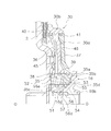
- FIG. 1 is a partial cross-sectional view of a torque converter including a lockup device according to an embodiment of the present invention.
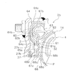
- the figure which shows the lockup apparatus of the torque converter shown by FIG. The figure which expands and shows the piston of the lockup apparatus shown by FIG. 2, and the structure which supports it.
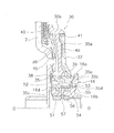
- the figure which expands and shows the damper mechanism of the lockup apparatus shown by FIG. The figure for demonstrating the flow of the hydraulic fluid at the time of lockup cancellation
- FIG. 1 is a longitudinal sectional view of a torque converter 1 in which an embodiment of the present invention is adopted.
- the torque converter 1 is a device for transmitting torque from a crankshaft of an engine to an input shaft of a transmission.
- An engine (not shown) is arranged on the left side of FIG. 1, and a transmission (not shown) is arranged on the right side of FIG. OO shown in FIG. 1 is a rotating shaft of the torque converter 1.
- the torque converter 1 mainly includes a front cover 2, a torque converter body including three types of impellers (impeller 3, turbine 4, and stator 5), and a lockup device 6.
- the front cover 2 is a disk-shaped member, and a center boss 8 is fixed to the inner peripheral end by welding.
- the center boss 8 is a cylindrical member extending in the axial direction, and is inserted into a center hole of a crankshaft (not shown).
- the front cover 2 is connected to the crankshaft of the engine via a flexible plate. That is, a plurality of bolts 9 are fixed at equal intervals in the circumferential direction on the outer peripheral side and the engine side surface of the front cover 2, and the outer peripheral portion of the flexible plate is moved to the front by the nuts screwed into the bolts 9. It is fixed to the cover 2.
- An outer peripheral cylindrical portion 2 a extending toward the axial transmission side is formed on the outer peripheral portion of the front cover 2.
- An impeller 3 is fixed to the tip of the outer peripheral cylindrical portion 2a by welding. As a result, the front cover 2 and the impeller 3 form a fluid chamber that is filled with hydraulic oil.
- the impeller 3 mainly includes an impeller shell 10 and a plurality of impeller blades 11 fixed inside thereof. And the front-end
- the turbine 4 is disposed to face the impeller 3 in the axial direction in the fluid chamber.
- the turbine 4 mainly includes a turbine shell 14, a plurality of turbine blades 15 fixed inside the turbine shell 14, and a turbine hub 16 fixed to the inner peripheral end of the turbine shell 14.
- the turbine shell 14 and the turbine hub 16 are fixed by a plurality of rivets 17.
- the turbine hub 16 includes a disc-shaped flange portion 16a to which an inner peripheral end portion of the turbine shell 14 is fixed, a cylindrical portion 16b formed to extend from the inner peripheral portion of the flange portion 16a to the front cover 2 side, have.
- the turbine shell 14 is fixed by the rivet 17 at the outer peripheral end of the flange portion 16a as described above.
- a spline hole 16c is formed in the inner peripheral portion of the cylindrical portion 16b and meshes with a spline shaft formed at the tip of the input shaft 18 of the transmission.
- a thrust washer 19 is disposed between the front end of the cylindrical portion 16 b of the turbine hub 16 and the front cover 2.
- a plurality of radial grooves penetrating from the inner periphery to the outer periphery are formed on the surface of the thrust washer 19 on the turbine hub 16 side. This groove functions as a lubricating groove and an oil passage.
- the stator 5 is a mechanism for rectifying the flow of hydraulic oil that is disposed between the inner periphery of the impeller 3 and the inner periphery of the turbine 4 and returns from the turbine 4 to the impeller 3.
- the stator 5 is integrally formed by casting with resin, aluminum alloy or the like.
- the stator 5 mainly includes an annular stator shell 20 and a plurality of stator blades 21 provided on the outer peripheral surface of the stator shell 20.
- the stator shell 20 is connected to a fixed shaft 23 via a one-way clutch 22.
- An annular recess 20a is formed on the surface of the stator shell 20 on the front cover 2 side at a position facing the rivet 17.
- the recess 20a is formed to avoid interference with the head of the rivet 17.
- the flange part 16a of the turbine hub 16 and the stator shell 20 can be brought close to the axial direction, and the axial dimension can be shortened.
- a plurality of recesses 20b that are recessed toward the impeller 3 are formed in part of the recesses 20a. Thereby, weight reduction is achieved.
- thrust bearings are disposed between the stator shell 20 and the impeller shell 10 and between the stator shell 20 and the flange portion 16a of the turbine hub 16, respectively.
- the lockup device 6 is disposed between the front cover 2 and the turbine 4 and directly transmits power from the front cover 2 to the turbine 4.
- the lockup device 6 includes a clutch portion 24 disposed between the front cover 2 and the turbine 4, and a damper mechanism 25 that transmits torque from the clutch portion 24 to the turbine.
- the clutch portion 24 is a hydraulically operated multi-plate type having a plurality of clutch plates, and transmits torque from the front cover 2 to the damper mechanism 25 or transmits torque between the front cover 2 and the damper mechanism 25. Cut off. As shown in an enlarged view in FIG. 2, the clutch portion 24 includes a clutch input member 26, a clutch output member 27, a first clutch plate 28 and a second clutch plate 29, and a piston 30. .
- the clutch input member 26 is an annular plate member and is fixed to the front cover 2.
- the inner peripheral end portion of the clutch input member 26 is bent toward the turbine 4, and a plurality of grooves are formed at predetermined intervals in the circumferential direction in the bent portion.
- the clutch output member 27 is disposed radially outward of the clutch input member 26.
- the clutch output member 27 is formed in an annular shape, a disc portion 27a formed in a disc shape, and a cylindrical portion 27b formed extending from the inner peripheral end of the disc portion 27a to the front cover 2 side. And have.
- the disc part 27 a is fixed to a power transmission plate (described later) constituting the damper mechanism 25 by a rivet 32.
- a plurality of grooves extending in the axial direction are formed in the cylindrical portion 27b at predetermined intervals in the circumferential direction.
- the first clutch plate 28 is formed in a disc shape, and a plurality of teeth that engage with a plurality of grooves of the bent portion of the clutch input member 26 are formed on the inner peripheral end of the first clutch plate 28. . With such a configuration, the first clutch plate 28 is movable in the axial direction with respect to the clutch input member 26 and is not relatively rotatable.
- the second clutch plate 29 is adjacent to the first clutch plate 28 and is disposed between the first clutch plate 28 and the clutch input member 26.
- the second clutch plate 29 is formed in a disc shape, and a plurality of teeth that engage with the plurality of grooves of the cylindrical portion 27 b of the clutch output member 27 are formed on the outer peripheral end of the second clutch plate 29. ing. With such a configuration, the second clutch plate 29 is movable in the axial direction with respect to the clutch output member 27 and is not relatively rotatable. An annular friction member is fixed to both surfaces of the second clutch plate 29.
- the piston 30 is disposed radially inward of the clutch output member 27 between the front cover 2 and the inner peripheral portion of the turbine 4.
- the piston 30 is formed in an annular shape, and includes a disk-shaped pressure receiving portion 30a and a pressing portion 30b formed on the outer peripheral portion of the pressure receiving portion 30a.
- the pressure receiving part 30a moves in the axial direction by the hydraulic pressure acting on the surface on the front cover 2 side and the surface on the turbine 4 side.
- the pressing part 30b extends to the front cover 2 side and the turbine 4 side with the pressure receiving part 30a as a boundary.
- the pressing portion 30 b moves to the turbine front cover 2 side and presses the first clutch plate 28 and the second clutch plate 29 with the clutch input member 26.
- the piston 30 is supported by a piston support mechanism 34 so as to be movable in the axial direction.
- the piston support mechanism 34 includes a support boss 35 and first and second disc-shaped flanges 36 and 37, respectively.
- the first flange 36 is a plate member constituting a lockup release oil chamber.
- the second flange 37 is a plate member that constitutes a lockup oil chamber.
- the supporting boss 35 is formed in an annular shape, and the cylindrical portion 16b of the turbine hub 16 is inserted therein. Further, the inner peripheral portion of the surface of the support boss 35 on the front cover 2 side is fixed to the front cover 2 by welding. A first seal member 38 and a second seal member 39 are provided on the outer peripheral surface of the support boss 35. The inner peripheral surface of the piston 30 is slidably in contact with the second seal member 39. Further, on the outer peripheral surface of the supporting boss 35, a small diameter portion 35a having a smaller diameter than other portions is formed on the turbine 4 side.
- the small diameter portion 35a protrudes further to the turbine side than the side surface of the supporting boss 35 on the turbine 4 side, and a protruding portion 35b is formed (in the figure, the protruding portion 35b is shown to be bent outward). )
- the first flange 36 is disposed on the front cover 2 side of the pressure receiving portion 30a of the piston 30, and is fixed to the front cover 2 by caulking a protrusion formed on the front cover 2. Note that a gap is provided between the first flange 36 and the front cover 2 for allowing the hydraulic oil to circulate, except for a portion that fixes both.
- a third seal member 40 is provided on the outer peripheral surface of the first flange 36, and the third seal member 40 is in contact with the inner peripheral surface of the pressing portion 30 b of the piston 30. Further, the inner peripheral surface of the first flange 36 is in contact with a first seal member 38 provided on the outer peripheral surface of the support boss 35.
- the second flange 37 is disposed on the turbine 4 side of the pressure receiving portion 30a of the piston 30.
- a fourth seal member 41 is provided on the outer peripheral surface of the second flange 37, and the fourth seal member 41 is in contact with the inner peripheral surface of the pressing portion 30 b of the piston 30.
- the inner peripheral surface of the second flange 37 is press-fitted into the small-diameter portion 35a of the supporting boss 35, and is fixed by caulking by bending the protruding portion 35b outward by rolling.
- a lockup releasing oil chamber 45 is formed between the pressure receiving portion 30a and the first flange 36, as shown in FIG.
- a lockup oil chamber 46 is formed between the pressure receiving portion 30 a and the second flange 37.
- a plurality of first oil passages 51 penetrating in the radial direction are formed in the cylindrical portion 16 b of the turbine hub 16.
- the supporting boss 35 is formed with a plurality of second oil passages 52, a plurality of third oil passages 53, and a plurality of fourth oil passages 54.
- the second oil passage 52 is formed through the support boss 35 in the radial direction, and communicates the inner peripheral side of the support boss 35 with the lockup release oil chamber 45.
- the third oil passage 53 is formed through the support boss 35 in the radial direction, and communicates the inner peripheral surface of the support boss 35 with the lockup oil chamber 46.
- the fourth oil passage 54 is formed so as to penetrate the support boss 35 in the axial direction, and communicates the space on the turbine 4 side of the support boss 35 with the space on the front cover 2 side.
- An annular groove 16d is formed on the inner peripheral surface of the tubular portion 16b of the turbine hub 16, and an annular recess 16e is formed on the outer periphery of the distal end of the tubular portion 16b.
- the opening on the inner peripheral side of the first oil passage 51 is located on the bottom surface of the groove 16d.
- the opening on the inner peripheral side of the second oil passage 52 is formed at a position facing the recess 16e.
- An annular groove 35 c is formed on the inner peripheral surface of the support boss 35.
- the opening on the inner peripheral side of the third oil passage 53 is located on the bottom surface of the groove 35c.
- an annular recess 35d that is recessed toward the front cover 2 is formed at the inner peripheral end.
- the recess 35d functions as an oil reservoir.
- the opening on the turbine 4 side is located in the recess 35d, and the opening on the front cover 2 side is located in the space between the front cover 2 and the end face of the supporting boss 35.
- a plurality of through holes 55 penetrating in the axial direction are formed at the inner peripheral end of the flange portion 16 a of the turbine hub 16. The plurality of through holes 55 are opposed to the recesses 35 d of the support boss 35.
- a collar 56 is press-fitted into the inner peripheral portion of the cylindrical portion 16 b of the turbine hub 16.
- the collar 56 is formed with a plurality of through holes 57 penetrating in the radial direction, and an annular groove 56 a is formed on the inner peripheral surface of the collar 56.
- the opening on the outer peripheral side of the through hole 57 of the collar 56 faces the groove 16 d formed on the inner surface of the tubular portion 16 b of the turbine hub 16.
- the damper mechanism 25 includes a power transmission plate 61 to which the clutch output member 27 is fixed, an output plate 62 that is fixed to the turbine shell 14, a plurality of torsion springs 63, an intermediate member 64, And a regulating plate 65.
- FIG. 4 shows only the damper mechanism 25 of the lockup device 6 and the configuration related thereto extracted.
- the power transmission plate 61 is formed in an annular shape, the disc portion 61a, the engaging portion 61b formed on the outer peripheral end of the disc portion 61a, and the inner peripheral end of the disc portion 61a on the front cover 2 side.
- the clutch output member 27 is fixed to the disc portion 61a by the rivet 32.
- the engaging portion 61 b is engaged with the circumferential end surface of the torsion spring 63.
- the output plate 62 engages with both ends in the circumferential direction of one set (two in this embodiment) of torsion springs 63 acting in series. As a result, torque input from the power transmission plate 61 is transmitted to the output plate 62 via the torsion spring 63 and further transmitted to the turbine 4.
- the intermediate member 64 is a member for causing one set (two) of torsion springs among a plurality of torsion springs 63 to act in series.
- the intermediate member 64 has an annular shape and a cross section formed in an inverted L shape.
- the intermediate member 64 is disposed on the outer peripheral side of the clutch input member 27, and includes an inner peripheral end portion 64a, a lateral support portion 64b, and an outer support portion 64c.
- the inner peripheral end portion 64 a extends to the inner peripheral side along the disc portion 61 a of the power transmission plate 61.
- the inner peripheral surface of the inner peripheral end portion 64a can come into contact with the outer peripheral surface of the clutch output member 27, whereby the intermediate member 64 is positioned in the radial direction. Further, the surface on the turbine 4 side of the inner peripheral end portion 64 a can abut on the disc portion 61 a of the power transmission plate 61. Thereby, the movement of the intermediate member 64 toward the turbine 4 is restricted.
- the lateral support portion 64b extends from the inner peripheral end portion 64a to the outer peripheral side, and supports the side portion of the torsion spring 63 on the front cover 2 side.
- a claw (not shown) for supporting the end surface of the set of torsion springs 63 extends from the lateral support portion 64b to the turbine 4 side.
- the outer support portion 64 c extends from the outer peripheral end of the lateral support portion 64 b to the turbine 4 side and supports the outer peripheral portion of the torsion spring 63.
- the regulation plate 65 is formed of a plate having a thickness smaller than that of the intermediate member 64.
- the restricting plate 65 is formed in an annular shape, and includes a fixed portion 65a and an axial restricting portion 65b.
- the fixing portion 65 a is formed in a disc shape, and is fixed to the clutch output member 27 and the power transmission plate 61 by the rivet 32.
- the axial direction restricting portion 65b is formed to extend from the fixed portion 65a to the outer periphery, and can contact the surface of the lateral support portion 64b of the intermediate member 64 on the front cover 2 side. Thereby, the movement of the intermediate member 64 toward the front cover 2 is restricted.
- the intermediate member 64 is positioned in the radial direction by the outer peripheral surface of the clutch output member 27.
- the intermediate member 64 is positioned in the axial direction by the power transmission plate 61 and the restriction plate 65.
- a power transmission plate support member 68 is provided on the inner peripheral side of the power transmission plate 61.
- the power transmission plate support member 68 is formed in an annular shape, and includes a fixed portion 68a, an axial first restricting portion 68b, a radial restricting portion 68c, and an axial second restricting portion 68d.
- the power transmission plate support member 68 is disposed on the outer peripheral side of the innermost peripheral portion (position indicated by P in FIG. 4) of the outlet portion of the hydraulic oil of the turbine 4.
- the fixed portion 68 a is fixed to the turbine shell 14 on the outer peripheral side from the pressure receiving portion 30 a of the piston 30.
- the first axial restricting portion 68b is formed by extending a part of the fixed portion 68a to the outer peripheral side.
- the first axial restricting portion 68 b can contact the surface of the disc portion 61 a of the power transmission plate 61 on the turbine 4 side.
- the radial direction restricting portion 68c is formed by bending a portion of the fixed portion 68a where the first axial restricting portion 68b is not formed to the front cover 2 side.
- the radial direction restricting portion 68 c can contact the inner peripheral surface of the inner peripheral cylindrical portion 61 c of the power transmission plate 61.
- the axial second restricting portion 68d is a protrusion that is formed on the distal end of the radial restricting portion 68c so as to protrude outward.
- the axial second restricting portion 68d can contact the tip of the inner peripheral cylindrical portion 61c.
- the power transmission plate 61 and the clutch output member 27 are positioned in the radial direction and the axial direction by the power transmission plate support member 68.
- the second oil chamber 46 is connected to the drain, and as shown in FIG. 5, the front end of the turbine hub 16 and the front cover 2 are connected from a control valve (not shown). Hydraulic oil is supplied between the two. This hydraulic oil passes through a groove formed in the thrust washer 19 and a recess 16e formed in the outer periphery of the tip end portion of the turbine hub 16, and further through the second oil passage 52 of the supporting boss 35 for releasing the lockup. It is supplied to the oil chamber 45. As a result, the piston 30 moves toward the turbine 4, and the pressing portion 30 b of the piston 30 is separated from the first clutch plate 28 and the second clutch plate 29.
- oil for operating the torque converter is supplied from between the input shaft 18 and the fixed shaft 23 of the transmission. As shown in FIG. 6, the hydraulic oil is guided between the support boss 35 and the front cover 2 through the through hole 55 and the fourth oil passage 54 of the turbine hub 4.
- the hydraulic oil supplied between the supporting boss 35 and the front cover 2 is guided to the outer peripheral side through a gap formed between the front cover 2 and the first flange 36, and further, the first clutch plate 28.
- the second cover plate 29 and the piston 30 are respectively guided to the outer peripheral end of the front cover 2.
- the torque converter body is supplied. Further, the hydraulic oil in the torque converter body flows through a control valve (not shown) through an oil passage between the stator shell 20 and the impeller shell 10.
- the torque from the front cover 2 is transmitted from the impeller 2 to the turbine 4 via the hydraulic oil, and further transmitted to the input shaft 18 of the transmission.
- the lockup release oil chamber 45 is connected to the drain, and as shown in FIG.
- the hydraulic oil is supplied to the inner peripheral portion of 56.
- the hydraulic oil is supplied to the lockup oil chamber 46 through the through hole 57 of the collar 56, the first oil passage 51, and the third oil passage 53.
- the piston 30 moves to the front cover 2 side, and the first clutch plate 28 and the second clutch plate 29 are pressed against each other.
- the power transmission plate 61 is positioned in the radial direction and the axial direction by the power transmission plate support member 68. Further, the intermediate member 64 is positioned by the clutch output member 27 to restrict the movement in the radial direction, and is positioned by the restriction member 65 and the power transmission plate 61 to restrict the movement in the axial direction.
- the power transmission plate 61 can be positioned in the radial direction and the axial direction by one power transmission plate support member 68, and the configuration is simplified.
- the piston 30 is moved by supplying hydraulic oil to the lockup release oil chamber 45 and the lockup oil chamber 46 to switch between the lockup state and the lockup release state. For this reason, the responsiveness at the time of switching becomes favorable. Moreover, the drag torque at the time of unlocking can be suppressed.
- both hydraulic chambers 45 are caused by centrifugal force when no hydraulic oil is supplied to any of the oil chambers. , 46 have the same hydraulic pressure. Therefore, the piston 30 can be kept in the neutral position.
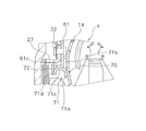
- FIG. 8 shows another embodiment of the power transmission plate support member.
- the power transmission plate support member 70 includes a first plate 71 and a second plate 72.
- the first plate 71 is formed in an annular shape, and includes a fixing portion 71a, an axial first restriction portion 71b, a radial direction restriction portion 71c, and a second plate support portion 71d.
- the second plate support portion 71d is formed by bending the radial direction restricting portion 71c to the inner peripheral side.
- the second plate 72 is formed in a disc shape, and an inner peripheral side portion thereof is fixed to the second plate support portion 71d of the first plate 71 by spot welding or the like. Further, the outer peripheral side portion of the second plate 72 is disposed so as to protrude further outward from the radial direction restricting portion 71 c of the first plate 71. The tip of the cylindrical portion 61 c of the power transmission plate 61 can come into contact with the second plate 72. That is, the second plate 72 functions as a second axial direction restricting portion.
- the power transmission plate 61 and the clutch output member 27 are positioned in the radial direction and the axial direction by the first and second plates 71 and 72 constituting the power transmission plate support member 70.
- FIG. 9 shows another embodiment of a mechanism for moving the piston.
- a piston support member 75 is provided on the outer peripheral surface of the tubular portion 16b ′ of the turbine hub 16 ′.
- the piston support member 75 is disposed between the front cover 2 and the turbine 4, and includes a disc portion 75 a that functions as a plate constituting a lockup oil chamber, and a cylindrical portion 75 b. .
- the disc portion 75 a extends so that the outer peripheral portion reaches the first clutch plate 28 and the second clutch plate 29.
- the cylindrical portion 75b extends from the inner peripheral end of the disc portion 75a to the front cover 2 side.
- the cylindrical portion 16b 'of the turbine hub 16' is inserted into the cylindrical portion 75b. And the front-end
- the piston 30 ′ is disposed between the disc portion 75 a of the piston support member 75 and the front cover 2.
- the piston 30 ' has a disk-shaped pressure receiving part 30a' and a pressing part 30b '.
- the inner peripheral surface of the pressure receiving portion 30 a ′ is slidably supported on the outer peripheral surface of the cylindrical portion 75 b of the piston support member 75.
- the pressing portion 30 b ′ is formed on the outer periphery of the pressure receiving portion 30 a ′ and can press the first clutch plate 28 and the second clutch plate 29.
- a first oil passage 76 and a second oil passage 77 are formed in the cylindrical portion 75 b of the piston support member 75.
- the first oil passage 76 is formed to communicate the space on the front cover 2 side of the piston 30 ′ with the space on the turbine 4 side of the piston support member 75.
- a through hole 55 ′ for supplying hydraulic oil from the control valve is formed in the space between the piston 30 ′ and the turbine 4 in the turbine flange 16 ′.
- the second oil passage 77 is a space (lock-up) between an oil passage (not shown) formed in the cylindrical portion 16 b ′ of the turbine hub 16 ′ and the piston 30 ′ and the pressure receiving portion 75 a of the piston support member 75.
- (Oil chamber) 78 is formed to communicate with each other.
- the lockup oil chamber 78 is connected to the drain, and the hydraulic oil from the control valve passes through the through hole 55 ′ and the second oil passage 77. It is supplied to the space on the front cover 2 side of the piston 30 ′.
- the piston 30 ′ moves to the turbine 4 side, and the pressing portion 30 b ′ of the piston 30 ′ moves away from the first clutch plate 28 and the second clutch plate 29.
- the hydraulic oil supplied to the space on the front cover 2 side of the piston 30 ′ is guided to the outer peripheral end of the front cover 2 as in the previous embodiment, and then supplied into the torque converter body.
- the torque from the front cover 2 is transmitted from the impeller 2 to the turbine 4 via the hydraulic oil, and further transmitted to the input shaft 18 of the transmission.
- the hydraulic oil is supplied to the lockup oil chamber 78 through the oil passage formed in the tubular portion 16b ′ of the turbine hub 16 ′ and the second oil passage 77. .
- FIG. 10 shows still another embodiment.
- a cone spring 80 is disposed in the lockup releasing oil chamber 45 of the first embodiment.
- Other configurations are the same as those of the first embodiment.
- the cone spring 80 is provided to urge the piston 30 toward the turbine 4 side. In this case, the lock-up can be released simply by supplying a low hydraulic pressure to the lock-up release oil chamber 45 in the lock-up release state. Further, depending on the load setting of the cone spring 80, it is not necessary to supply hydraulic oil for releasing the lockup.
- the axial dimension of the clutch portion can be particularly shortened.
Landscapes
- Engineering & Computer Science (AREA)
- General Engineering & Computer Science (AREA)
- Mechanical Engineering (AREA)
- Control Of Fluid Gearings (AREA)
- Mechanical Operated Clutches (AREA)
Abstract
多板型のロックアップ装置において、ピストンや油室の配置を工夫することによって、軸方向の小型化を図る。このロックアップ装置は、クラッチ部(24)及びダンパ機構(25)を備えている。クラッチ部(24)は、クラッチ入力部材(26)と、クラッチ出力部材(27)と、ドライブプレート(28)及びドリブンプレート(29)と、第2フランジ(37)と、ピストン(30)と、を有している。第2フランジ(37)は、フロントカバー(2)とタービン(4)内周部との間にフロントカバー(2)に対して軸方向移動不能に設けられ、ロックアップ用の油室を構成する。ピストン(30)は、フロントカバー(2)と第2フランジ(37)との間に設けられ、第2フランジ(37)との間にロックアップ用油室(46)を構成し、ロックアップ用油室(46)に供給される作動油によってフロントカバー(2)側に移動する。
Description
本発明は、ロックアップ装置、特に、フロントカバーからのトルクをトルクコンバータのタービンを介してトランスミッション側の部材に伝達するためのトルクコンバータのロックアップ装置に関する。
トルクコンバータには、トルクをフロントカバーからタービンに直接伝達するためのロックアップ装置が設けられている場合が多い。このロックアップ装置は、フロントカバーに摩擦連結可能なピストンと、ピストンに固定されるドライブプレートと、ドライブプレートに支持される複数のトーションスプリングと、複数のトーションスプリングによってピストン及びドライブプレートに回転方向に弾性的に連結されるドリブンプレートとを有している。ドリブンプレートはタービンに固定されている。
また、特許文献1に示されるように、ロックアップ装置のクラッチ容量を大きくするために、複数のクラッチプレートを用いた、いわゆる多板型のロックアップ装置も提案されている。
この特許文献1に示されたロックアップ装置は、フロントカバーとタービンとの間に配置されたクラッチ部と、クラッチ部の出力部材に連結された動力伝達のためのプレートと、動力伝達プレートとタービンとを弾性的に連結する複数のトーションスプリングと、を備えている。クラッチ部は、複数のクラッチプレートと、フロントカバーと複数のクラッチプレートとの間に配置されたピストンと、を有している。
ここでは、ピストンの背面に油圧が供給されることによってピストンが複数のクラッチプレート側に移動し、複数のクラッチプレートが互いに押圧されてロックアップ状態(動力伝達状態)となる。この状態では、フロントカバーからのトルクは、クラッチ部を介して動力伝達プレートに伝達され、さらに複数のトーションスプリングを介してタービンに伝達される。
特許文献1に示された装置では、フロントカバーとタービン内周との間に、クラッチ部の部材や動力伝達プレートを支持するための部材が配置されている。このために、クラッチ部はこれらの径方向外方に配置せざるを得ない。
また、クラッチ部においては、フロントカバーとピストンとの間にロックアップ用の油室が形成され、ピストンとタービンとの間に複数のクラッチプレート及びこれらを支持するためのバックプレートが配置されている。
以上のような従来の多板型のロックアップ装置では、軸方向スペースを短縮化することが困難である。
本発明の課題は、多板型のロックアップ装置において、ピストンや油室の配置を工夫することによって、軸方向の小型化を図ることにある。
本発明の第1側面に係るトルクコンバータのロックアップ装置は、フロントカバーからのトルクをトルクコンバータのタービンを介してトランスミッション側の部材に伝達するための装置であって、クラッチ部と、ダンパ機構と、を備えている。クラッチ部は、フロントカバーとタービンとの間に配置され、トルクを伝達あるいは遮断する。ダンパ機構は、クラッチ部からのトルクをタービンに伝達するとともに、捩り振動を吸収・減衰する。また、クラッチ部は、フロントカバーとタービンとの間に配置されフロントカバーに連結されたクラッチ入力部材と、ダンパ機構にトルクを出力するクラッチ出力部材と、クラッチ入力部材とクラッチ出力部材との間でトルク伝達を行うための複数のクラッチプレートと、円板状のロックアップ用油室プレートと、ピストンと、を有している。ロックアップ用油室プレートは、フロントカバーとタービン内周部との間にフロントカバーに対して軸方向移動不能に設けられ、ロックアップ用の油室を構成する。ピストンは、フロントカバーとロックアップ用油室プレートとの間に軸方向移動自在に設けられ、ロックアップ用油室プレートとの間にロックアップ用油室を構成し、ロックアップ用油室に供給される作動油によってフロントカバー側に移動して複数のクラッチプレートを互いに押圧する。
この装置では、ロックアップ時には、ロックアップ用油室に作動油が供給される。これにより、ピストンはフロントカバー側に移動し、複数のクラッチプレートを押圧する。この状態では、フロントカバーからのトルクは、クラッチ部からダンパ機構を介してタービンに出力される。
ここでは、フロントカバーとタービンとの間にロックアップ用油室が形成され、ピストンはタービン側からフロントカバー側に移動してロックアップ状態になるので、従来のロックアップ装置に比較して、軸方向寸法を短縮することができる。
本発明の第2側面に係るトルクコンバータのロックアップ装置は、第1側面のロックアップ装置において、タービンは、トランスミッション側の部材に連結される筒状部を内周端部に有している。また、クラッチ部は環状のボスを有している。環状のボスは、ロックアップ用油室プレートの内周部からフロントカバー側に延びるとともにフロントカバーに固定され、外周面をピストンが軸方向に摺動する。また、環状のボスは、タービンの筒状部が内周部に挿入されており、ロックアップ用油室に作動油を供給するための油路が形成されている。
本発明の第3側面に係るトルクコンバータのロックアップ装置は、第2側面のロックアップ装置において、環状ボスはロックアップ用油室プレートと別部材で形成されており、ロックアップ用油室プレートは環状ボスの外周面に固定されている。
本発明の第4側面に係るトルクコンバータのロックアップ装置は、第2側面のロックアップ装置において、環状ボスは、ロックアップ用油室プレートの内周端部をフロントカバー側に延長して形成されている。
本発明の第5側面に係るトルクコンバータのロックアップ装置は、第2から第4側面のいずれかのロックアップ装置において、クラッチ部は、フロントカバーとピストンとの間にフロントカバーに対して軸方向移動不能に設けられ、ロックアップ解除用の油室を構成する円板状のロックアップ解除用油室プレートをさらに有している。
ここでは、ロックアップ用油室及びロックアップ解除用油室が形成されているので、ロックアップとロックアップ解除の切替時の応答性が向上する。
本発明の第6側面に係るトルクコンバータのロックアップ装置は、第5側面のロックアップ装置において、ロックアップ用油室とロックアップ解除用油室の内外径は同じである。
ここで、ロックアップ用油室とロックアップ解除用油室に作動油が供給されていない場合であっても、遠心力によってピストンに油圧が作用する。しかし、ここでは、両油室の内外径が同じであるので、遠心力によって両油室で発生する油圧は等しくなる。したがって、遠心力により作用する油圧によってピストンが移動させられるのを抑えることができる。
本発明の第7側面に係るトルクコンバータのロックアップ装置は、第5又は第6側面のロックアップ装置において、環状ボスには、ロックアップ解除用油室に作動油を供給するための油路が形成されている。
本発明の第8側面に係るトルクコンバータのロックアップ装置は、第1から第7側面のいずれかのロックアップ装置において、クラッチ入力部材は、円板状に形成されるとともに内周端部がタービン側に延びている。クラッチ出力部材は、クラッチ入力部材の径方向外方に配置され、円板状に形成されるとともに内周端部がフロントカバー側に延びている。また、複数のクラッチプレートは、内周端部がクラッチ入力部材の内周端部に軸方向移動自在かつ相対回転不能に係合する円板状の第1クラッチプレートと、外周端部がクラッチ出力部材の内周端部に軸方向移動自在かつ相対回転不能に係合する円板状の第2クラッチプレートと、を有し、ピストン及びロックアップ用油室プレートはクラッチ出力部材の径方向内方に配置されている。
以上のように本発明では、特にクラッチ部の軸方向寸法を短縮することができる。
-第1実施形態-
[トルクコンバータの全体構成]
図1は本発明の一実施形態が採用されたトルクコンバータ1の縦断面図である。トルクコンバータ1は、エンジンのクランクシャフトからトランスミッションの入力シャフトにトルクを伝達するための装置である。図1の左側に図示しないエンジンが配置され、図1の右側に図示しないトランスミッションが配置されている。図1に示すO-Oがトルクコンバータ1の回転軸である。
[トルクコンバータの全体構成]
図1は本発明の一実施形態が採用されたトルクコンバータ1の縦断面図である。トルクコンバータ1は、エンジンのクランクシャフトからトランスミッションの入力シャフトにトルクを伝達するための装置である。図1の左側に図示しないエンジンが配置され、図1の右側に図示しないトランスミッションが配置されている。図1に示すO-Oがトルクコンバータ1の回転軸である。
トルクコンバータ1は、主に、フロントカバー2と、3種の羽根車(インペラ3,タービン4及びステータ5)からなるトルクコンバータ本体と、ロックアップ装置6と、を備えている。
[フロントカバー]
フロントカバー2は、円板状の部材であって、内周端にはセンターボス8が溶接により固定されている。センターボス8は、軸方向に延びる円筒形状の部材であり、クランクシャフト(図示せず)の中心孔内に挿入されるものである。
フロントカバー2は、円板状の部材であって、内周端にはセンターボス8が溶接により固定されている。センターボス8は、軸方向に延びる円筒形状の部材であり、クランクシャフト(図示せず)の中心孔内に挿入されるものである。
なお、図示していないが、フロントカバー2はフレキシブルプレートを介してエンジンのクランクシャフトに連結されるようになっている。すなわち、フロントカバー2の外周側かつエンジン側の面には、円周方向に等間隔で複数のボルト9が固定されており、このボルト9に螺合するナットによって、フレキシブルプレートの外周部がフロントカバー2に固定されている。
フロントカバー2の外周部には、軸方向トランスミッション側に延びる外周側筒状部2aが形成されている。この外周側筒状部2aの先端にインペラ3が溶接によって固定されている。この結果、フロントカバー2とインペラ3とによって、内部に作動油が充填される流体室が形成されている。
[インペラ]
インペラ3は、主に、インペラシェル10と、その内側に固定された複数のインペラブレード11と、から構成されている。そして、インペラシェル10の外周側先端部が、前述のように、フロントカバー2に溶接されている。なお、インペラハブ10の内周端部には、トランスミッション側に延びる筒状部が形成されている。
インペラ3は、主に、インペラシェル10と、その内側に固定された複数のインペラブレード11と、から構成されている。そして、インペラシェル10の外周側先端部が、前述のように、フロントカバー2に溶接されている。なお、インペラハブ10の内周端部には、トランスミッション側に延びる筒状部が形成されている。
[タービン]
タービン4は流体室内でインペラ3に対して軸方向に対向して配置されている。タービン4は、主に、タービンシェル14と、その内部に固定された複数のタービンブレード15と、タービンシェル14の内周端部に固定されたタービンハブ16と、から構成されている。タービンシェル14とタービンハブ16とは複数のリベット17によって固定されている。
タービン4は流体室内でインペラ3に対して軸方向に対向して配置されている。タービン4は、主に、タービンシェル14と、その内部に固定された複数のタービンブレード15と、タービンシェル14の内周端部に固定されたタービンハブ16と、から構成されている。タービンシェル14とタービンハブ16とは複数のリベット17によって固定されている。
タービンハブ16は、タービンシェル14の内周端部が固定された円板状のフランジ部16aと、フランジ部16aの内周部からフロントカバー2側に延びて形成された筒状部16bと、を有している。そして、フランジ部16aの外周端部において、前述のように、リベット17によってタービンシェル14が固定されている。また、筒状部16bの内周部にはスプライン孔16cが形成されており、トランスミッションの入力シャフト18の先端に形成されたスプライン軸と噛み合っている。
なお、タービンハブ16の筒状部16bの先端とフロントカバー2との間には、スラストワッシャ19が配置されている。スラストワッシャ19のタービンハブ16側の面には、内周から外周に貫通する複数の放射状の溝が形成されている。この溝は、潤滑用の溝及び油路として機能するものである。
[ステータ]
ステータ5は、インペラ3の内周部とタービン4の内周部との間に配置され、タービン4からインペラ3に戻る作動油の流れを整流するための機構である。ステータ5は樹脂やアルミ合金等で鋳造により一体に形成されている。ステータ5は、主に、環状のステータシェル20と、ステータシェル20の外周面に設けられた複数のステータブレード21と、を有している。ステータシェル20は、ワンウェイクラッチ22を介して固定シャフト23に連結されている。
ステータ5は、インペラ3の内周部とタービン4の内周部との間に配置され、タービン4からインペラ3に戻る作動油の流れを整流するための機構である。ステータ5は樹脂やアルミ合金等で鋳造により一体に形成されている。ステータ5は、主に、環状のステータシェル20と、ステータシェル20の外周面に設けられた複数のステータブレード21と、を有している。ステータシェル20は、ワンウェイクラッチ22を介して固定シャフト23に連結されている。
なお、ステータシェル20のフロントカバー2側の面には、リベット17と対向する位置に、環状の凹部20aが形成されている。この凹部20aはリベット17の頭部との干渉を避けるために形成されたものである。これにより、タービンハブ16のフランジ部16aとステータシェル20とを軸方向に近づけることができ、軸方向寸法の短縮化を可能にしている。また、凹部20aの一部には、インペラ3側に凹む複数の凹部20bが形成されている。これにより軽量化が図られている。
また、ステータシェル20とインペラシェル10との間、及びステータシェル20とタービンハブ16のフランジ部16aとの間には、それぞれスラストベアリングが配置されている。
[ロックアップ装置]
ロックアップ装置6は、フロントカバー2とタービン4との間に配置され、フロントカバー2からタービン4に動力を直接伝達するものである。このロックアップ装置6は、フロントカバー2とタービン4との間に配置されたクラッチ部24と、クラッチ部24からのトルクをタービンに伝達するダンパ機構25と、を備えている。
ロックアップ装置6は、フロントカバー2とタービン4との間に配置され、フロントカバー2からタービン4に動力を直接伝達するものである。このロックアップ装置6は、フロントカバー2とタービン4との間に配置されたクラッチ部24と、クラッチ部24からのトルクをタービンに伝達するダンパ機構25と、を備えている。
<クラッチ部>
クラッチ部24は、油圧作動式で複数のクラッチプレートを有する多板型であり、フロントカバー2からのトルクをダンパ機構25に伝達し、あるいはフロントカバー2とダンパ機構25との間のトルク伝達を遮断する。このクラッチ部24は、図2に拡大して示すように、クラッチ入力部材26と、クラッチ出力部材27と、第1クラッチプレート28及び第2クラッチプレート29と、ピストン30と、を有している。
クラッチ部24は、油圧作動式で複数のクラッチプレートを有する多板型であり、フロントカバー2からのトルクをダンパ機構25に伝達し、あるいはフロントカバー2とダンパ機構25との間のトルク伝達を遮断する。このクラッチ部24は、図2に拡大して示すように、クラッチ入力部材26と、クラッチ出力部材27と、第1クラッチプレート28及び第2クラッチプレート29と、ピストン30と、を有している。
クラッチ入力部材26は、環状のプレート部材であり、フロントカバー2に固定されている。クラッチ入力部材26の内周端部は、タービン4側に折り曲げられ、この折り曲げ部には円周方向に所定の間隔で複数の溝が形成されている。
クラッチ出力部材27はクラッチ入力部材26の径方向外方に配置されている。クラッチ出力部材27は、環状に形成されており、円板状に形成された円板部27aと、円板部27aの内周端部からフロントカバー2側に延びて形成された筒状部27bと、を有している。円板部27aはダンパ機構25を構成する動力伝達プレート(後述)にリベット32により固定されている。筒状部27bには、軸方向に延びる複数の溝が円周方向に所定の間隔で形成されている。
第1クラッチプレート28は円板状に形成されており、第1クラッチプレート28の内周端には、クラッチ入力部材26の折り曲げ部の複数の溝に係合する複数の歯が形成されている。このような構成により、第1クラッチプレート28は、クラッチ入力部材26に対して軸方向に移動自在かつ相対回転不能である。
第2クラッチプレート29は、第1クラッチプレート28に隣接し、第1クラッチプレート28とクラッチ入力部材26との間に配置されている。第2クラッチプレート29は、円板状に形成されており、第2クラッチプレート29の外周端には、クラッチ出力部材27の筒状部27bの複数の溝に係合する複数の歯が形成されている。このような構成により、第2クラッチプレート29は、クラッチ出力部材27に対して軸方向に移動自在かつ相対回転不能である。また、第2クラッチプレート29の両面には、環状の摩擦部材が固定されている。
ピストン30は、フロントカバー2とタービン4の内周部との間で、クラッチ出力部材27の径方向内方に配置されている。ピストン30は、環状に形成されており、円板状の受圧部30aと、受圧部30aの外周部に形成された押圧部30bと、を有している。受圧部30aは、フロントカバー2側の面及びタービン4側の面に作用する油圧によって、軸方向に移動する。押圧部30bは、受圧部30aを境にフロントカバー2側及びタービン4側に延びている。この押圧部30bは、タービンフロントカバー2側に移動して、クラッチ入力部材26との間に、第1クラッチプレート28及び第2クラッチプレート29を押圧する。
ピストン30は、ピストン支持機構34によって軸方向に移動自在に支持されている。ピストン支持機構34は、支持用ボス35と、それぞれ円板状の第1フランジ36及び第2フランジ37と、を有している。後述するように、第1フランジ36はロックアップ解除用油室を構成するプレート部材である。また、第2フランジ37はロックアップ用油室を構成するプレート部材である。
支持用ボス35は、環状に形成され、内部にタービンハブ16の筒状部16bが挿入されている。また、支持用ボス35のフロントカバー2側の面の内周部がフロントカバー2に溶接により固定されている。支持用ボス35の外周面には、第1シール部材38及び第2シール部材39が設けられている。そして、ピストン30の内周面が第2シール部材39に摺動自在に接触している。また、支持用ボス35の外周面において、タービン4側には他の部分より小径の小径部35aが形成されている。この小径部35aは支持用ボス35のタービン4側の側面よりさらにタービン側に突出しており、突出部35bが形成されている(図では、突出部35bが外方に折り曲げられた状態を示している)。
第1フランジ36は、ピストン30の受圧部30aのフロントカバー2側に配置され、フロントカバー2に形成された突起部をかしめることによってフロントカバー2に固定されている。なお、第1フランジ36とフロントカバー2との間には、両者を固定する部分を除いて、作動油を流通させるための隙間が設けられている。第1フランジ36の外周面には第3シール部材40が設けられ、第3シール部材40はピストン30の押圧部30bの内周面に接触している。また、第1フランジ36の内周面は支持用ボス35の外周面に設けられた第1シール部材38に接触している。
第2フランジ37はピストン30の受圧部30aのタービン4側に配置されている。第2フランジ37の外周面には第4シール部材41が設けられ、第4シール部材41はピストン30の押圧部30bの内周面に接触している。また、第2フランジ37の内周面は支持用ボス35の小径部35aに圧入され、突出部35bを外方にローリング加工によって折り曲げることによってかしめ固定されている。
<ピストンを移動させるための構造>
以上のようなピストン支持機構34によって、図2及び図2の拡大部分図である図3に示すように、受圧部30aと第1フランジ36との間にはロックアップ解除用油室45が構成され、受圧部30aと第2フランジ37との間にはロックアップ用油室46が構成されている。これらの両油室45,46は内外径が等しい。
以上のようなピストン支持機構34によって、図2及び図2の拡大部分図である図3に示すように、受圧部30aと第1フランジ36との間にはロックアップ解除用油室45が構成され、受圧部30aと第2フランジ37との間にはロックアップ用油室46が構成されている。これらの両油室45,46は内外径が等しい。
タービンハブ16の筒状部16bには、径方向に貫通する複数の第1油路51が形成されている。また、支持用ボス35には、複数の第2油路52と、複数の第3油路53と、複数の第4油路54と、が形成されている。第2油路52は、支持用ボス35を径方向に貫通して形成されており、支持用ボス35の内周側とロックアップ解除用油室45とを連通している。第3油路53は、支持用ボス35を径方向に貫通して形成されており、支持用ボス35の内周面とロックアップ用油室46とを連通している。第4油路54は、支持用ボス35を軸方向に貫通して形成されており、支持用ボス35のタービン4側の空間とフロントカバー2側の空間とを連通している。
タービンハブ16の筒状部16bの内周面には環状の溝16dが形成され、また筒状部16bの先端外周には環状の凹部16eが形成されている。第1油路51の内周側の開口は溝16dの底面に位置している。また、第2油路52の内周側の開口は、凹部16eに対向する位置に形成されている。
支持用ボス35の内周面には環状の溝35cが形成されている。第3油路53の内周側の開口は、この溝35cの底面に位置している。さらに、支持用ボス35のタービン4側の面において、内周端部には、フロントカバー2側に凹む環状の凹部35dが形成されている。この凹部35dは油溜まりとして機能する。
第4油路54は、タービン4側の開口が凹部35dに位置し、フロントカバー2側の開口がフロントカバー2と支持用ボス35の端面との間の空間に位置している。なお、タービンハブ16のフランジ部16aの内周端部には、軸方向に貫通する複数の貫通孔55が形成されている。複数の貫通孔55は支持用ボス35の凹部35dに対向している。
タービンハブ16の筒状部16bの内周部には、カラー56が圧入されている。カラー56には径方向に貫通する複数の貫通孔57が形成されており、カラー56の内周面には環状の溝56aが形成されている。カラー56の貫通孔57の外周側の開口は、タービンハブ16の筒状部16bの内面に形成された溝16dに対向している。
<ダンパ機構>
ダンパ機構25は、図4に示すように、クラッチ出力部材27が固定された動力伝達プレート61と、タービンシェル14に固定された出力プレート62と、複数のトーションスプリング63と、中間部材64と、規制プレート65と、を有している。なお、図4は、ロックアップ装置6のうちのダンパ機構25及びそれに関連する構成のみを抽出して示したものである。
ダンパ機構25は、図4に示すように、クラッチ出力部材27が固定された動力伝達プレート61と、タービンシェル14に固定された出力プレート62と、複数のトーションスプリング63と、中間部材64と、規制プレート65と、を有している。なお、図4は、ロックアップ装置6のうちのダンパ機構25及びそれに関連する構成のみを抽出して示したものである。
動力伝達プレート61は、環状に形成されており、円板部61aと、円板部61aの外周端に形成された係合部61bと、円板部61aの内周端にフロントカバー2側に延びて形成された内周筒状部61cと、を有している。円板部61aには、前述のように、クラッチ出力部材27がリベット32により固定されている。係合部61bは、トーションスプリング63の周方向の端面に係合している。
出力プレート62は、直列に作用する1組(この実施形態では2個)のトーションスプリング63の周方向両端に係合する。これにより、動力伝達プレート61から入力されたトルクがトーションスプリング63を介して出力プレート62に伝達され、さらにタービン4に伝達される。
中間部材64は、複数のトーションスプリング63のうちの1組(2個)のトーションスプリングを直列に作用させるための部材である。中間部材64は、環状であり、断面は逆L字状に形成されている。中間部材64は、クラッチ入力部材27の外周側に配置されており、内周端部64aと、横支持部64bと、外支持部64cと、を有している。
内周端部64aは動力伝達プレート61の円板部61aに沿って内周側に延びている。内周端部64aの内周面は、クラッチ出力部材27の外周面に当接可能であり、これにより、中間部材64は径方向に位置決めされている。また、内周端部64aのタービン4側の面は動力伝達プレート61の円板部61aに当接可能である。これにより、中間部材64のタービン4側への移動が規制されている。横支持部64bは、内周端部64aから外周側に延び、トーションスプリング63のフロントカバー2側の側部を支持している。また、この横支持部64bから、1組のトーションスプリング63の端面を支持する爪(図示せず)が、タービン4側に延びて形成されている。外支持部64cは横支持部64bの外周端からタービン4側に延び、トーションスプリング63の外周部を支持している。
規制プレート65は、中間部材64より板厚の薄いプレートにより形成されている。規制プレート65は、環状に形成されており、固定部65aと、軸方向規制部65bと、を有している。
固定部65aは、円板状に形成されており、リベット32によりクラッチ出力部材27及び動力伝達プレート61に固定されている。軸方向規制部65bは、固定部65aから外周に延びて形成されており、中間部材64の横支持部64bのフロントカバー2側の面に当接可能である。これにより、中間部材64のフロントカバー2側への移動が規制されている。
以上のような構成により、中間部材64は、クラッチ出力部材27の外周面によって径方向に位置決めされている。また、中間部材64は、動力伝達プレート61と規制プレート65によって軸方向に位置決めされている。
<動力伝達プレートの位置決め構造>
図4に示すように、動力伝達プレート61の内周側には、動力伝達プレート支持部材68が設けられている。動力伝達プレート支持部材68は、環状に形成され、固定部68aと、軸方向第1規制部68bと、径方向規制部68cと、軸方向第2規制部68dと、を有している。この動力伝達プレート支持部材68は、タービン4の作動油の出口部の最内周部(図4のPで示す位置)より外周側に配置されている。
図4に示すように、動力伝達プレート61の内周側には、動力伝達プレート支持部材68が設けられている。動力伝達プレート支持部材68は、環状に形成され、固定部68aと、軸方向第1規制部68bと、径方向規制部68cと、軸方向第2規制部68dと、を有している。この動力伝達プレート支持部材68は、タービン4の作動油の出口部の最内周部(図4のPで示す位置)より外周側に配置されている。
固定部68aは、ピストン30の受圧部30aより外周側においてタービンシェル14に固定されている。軸方向第1規制部68bは固定部68aの一部を外周側に延長して形成されている。軸方向第1規制部68bは動力伝達プレート61の円板部61aのタービン4側の面に当接可能である。径方向規制部68cは、固定部68aの軸方向第1規制部68bが形成されていない部分をフロントカバー2側に折り曲げて形成されている。径方向規制部68cは動力伝達プレート61の内周筒状部61cの内周面に当接可能である。軸方向第2規制部68dは径方向規制部68cの先端に外周側に突出して形成された突起部である。軸方向第2規制部68dは内周筒状部61cの先端に当接可能である。
以上のような構成により、動力伝達プレート61及びクラッチ出力部材27は、動力伝達プレート支持部材68によって、径方向及び軸方向に位置決めされている。
[動作]
ロックアップ装置6において、ロックアップを解除する場合には、第2油室46はドレンに接続されるとともに、図5に示すように、図示しないコントロールバルブからタービンハブ16の前端部とフロントカバー2との間に作動油が供給される。この作動油は、スラストワッシャ19に形成された溝及びタービンハブ16の先端部外周に形成された凹部16eを経由し、さらに支持用ボス35の第2油路52を経由してロックアップ解除用油室45に供給される。これにより、ピストン30はタービン4側に移動し、ピストン30の押圧部30bは第1クラッチプレート28及び第2クラッチプレート29から離れる。
ロックアップ装置6において、ロックアップを解除する場合には、第2油室46はドレンに接続されるとともに、図5に示すように、図示しないコントロールバルブからタービンハブ16の前端部とフロントカバー2との間に作動油が供給される。この作動油は、スラストワッシャ19に形成された溝及びタービンハブ16の先端部外周に形成された凹部16eを経由し、さらに支持用ボス35の第2油路52を経由してロックアップ解除用油室45に供給される。これにより、ピストン30はタービン4側に移動し、ピストン30の押圧部30bは第1クラッチプレート28及び第2クラッチプレート29から離れる。
また、トランスミッションの入力シャフト18と固定シャフト23との間からトルクコンバータ作動用の油が供給される。この作動油は、図6に示すように、タービンハブ4の貫通孔55及び第4油路54を経由して支持用ボス35とフロントカバー2との間に導かれる。
なお、貫通孔55と第4油路54との間には凹部35dが形成されているので、貫通孔55から支持用ボス35側に供給された作動油はいったん凹部35dに留まり、その後第4油路54側に導かれる。したがって、貫通孔55と第4油路54とが軸方向に一致していない場合であっても、これらの油路55,54間を作動油はスムーズに流れることになる。
支持用ボス35とフロントカバー2との間に供給された作動油は、フロントカバー2と第1フランジ36との間に形成された隙間を通って外周側に導かれ、さらに第1クラッチプレート28、第2クラッチプレート29、ピストン30のそれぞれの間を通ってフロントカバー2の外周端部に導かれる。その後、トルクコンバータ本体に供給される。また、トルクコンバータ本体内の作動油は、ステータシェル20とインペラシェル10との間の油路を介して図示しないコントロールバルブに流れる。
以上のような状態では、フロントカバー2からのトルクは、作動油を介してインペラ2からタービン4に伝達され、さらにトランスミッションの入力シャフト18に伝達される。
一方、ロックアップ装置において、ロックアップ状態(動力伝達状態)にする場合は、ロックアップ解除用油室45をドレンに接続するとともに、図7に示すように、入力シャフト18の内部を通ってカラー56の内周部に作動油が供給される。この作動油は、カラー56の貫通孔57、第1油路51、第3油路53の経路でロックアップ用油室46に供給される。これにより、ピストン30はフロントカバー2側に移動し、第1クラッチプレート28及び第2クラッチプレート29が互いに押圧される。
以上のような状態では、フロントカバー2からのトルクは、クラッチ入力部材26→第1クラッチプレート28及び第2クラッチプレート29→クラッチ出力部材27の経路を介してダンパ機構25に伝達される。
ダンパ機構25においては、クラッチ部24から動力伝達プレート61に入力されたトルクは、トーションスプリング63及び出力プレート62を介してタービン4に伝達され、さらにタービンハブ16を介してトランスミッションの入力シャフト18に伝達される。
以上のようなロックアップ装置6において、動力伝達プレート61は動力伝達プレート支持部材68によって径方向及び軸方向に位置決めされる。また、中間部材64はクラッチ出力部材27によって位置決めされて径方向の移動が規制され、また規制部材65及び動力伝達プレート61によって位置決めされて軸方向の移動が規制される。
[特徴]
(1)動力伝達プレート61を、1つの動力伝達プレート支持部材68によって径方向及び軸方向に位置決めでき、構成が簡単になる。
(1)動力伝達プレート61を、1つの動力伝達プレート支持部材68によって径方向及び軸方向に位置決めでき、構成が簡単になる。
(2)動力伝達プレート支持部材68はタービンシェル14に固定されているので、タービン内周部とフロントカバー2との間に他の部材を配置するスペースを確保できる。本実施形態では、このスペースにロックアップ装置のピストン30及び油室を構成するための部材を配置しているので、装置全体の軸方向寸法を短縮できる。
(3)クラッチ部24のクラッチ入力部材26をフロントカバーに固定するとともに、ピストン30をタービン4側からフロントカバー2側に向けて移動させ、ロックアップ状態にするので、ピストンをフロントカバー側に設けてタービン側に移動させてロックアップ状態にする場合に比較して、軸方向寸法を短縮できる。
(4)クラッチ出力部材27によって中間部材64の径方向の移動を規制しているので、ロックアップ装置6の占めるスペースを小さくすることができる。また、厚みの比較的薄い規制部材65と動力伝達プレート61によって中間部材64の軸方向の移動を規制しているので、さらに軸方向の省スペース化を図ることができる。特に多板型のクラッチ部では、軸方向スペースが長くなるので、本実施形態の構成を用いることによって軸方向スペースを抑えることができる。
(5)ピストン30を、ロックアップ解除用油室45及びロックアップ用油室46に作動油を供給することによって移動させ、ロックアップ状態とロックアップ解除状態を切り替えている。このため、切替時の応答性が良好になる。また、ロックアップ解除時のドラグトルクを抑えることができる。
(6)ロックアップ用油室46が他の作動油回路と独立して設けられているために、トルクコンバータ本体に供給される作動油を利用してロックアップ状態にする場合に比較して、安定したロックアップトルク容量を得ることができる。
(7)ロックアップ解除用油室45とロックアップ用油室46の内外径が同じであるために、いずれの油室にも作動油が供給されていないときに、遠心力によって両油室45,46に発生する油圧が同じになる。したがって、ピストン30を中立位置に保つことができる。
-第2実施形態-
図8に動力伝達プレート支持部材の他の実施形態を示す。この動力伝達プレート支持部材70は第1プレート71及び第2プレート72から構成されている。
図8に動力伝達プレート支持部材の他の実施形態を示す。この動力伝達プレート支持部材70は第1プレート71及び第2プレート72から構成されている。
第1プレート71は、環状に形成されており、固定部71a、軸方向第1規制部71b、及び径方向規制部71c、及び第2プレート支持部71dから構成されている。固定部71a、軸方向第1規制部71b、及び径方向規制部71cについては、第1実施形態の動力伝達プレート支持部材68における固定部68a、軸方向第1規制部68b、及び径方向規制部68cと同じ構成である。第2プレート支持部71dは、径方向規制部71cを内周側に折り曲げて形成されている。
第2プレート72は円板状に形成されており、その内周側部分が第1プレート71の第2プレート支持部71dにスポット溶接等により固定されている。また、第2プレート72の外周側部分は、第1プレート71の径方向規制部71cからさらに外周に突出するように配置されている。そして、この第2プレート72に、動力伝達プレート61の筒状部61cの先端が当接可能になっている。すなわち、第2プレート72は第2軸方向規制部として機能している。
以上のような構成により、動力伝達プレート61及びクラッチ出力部材27は、動力伝達プレート支持部材70を構成する第1及び第2プレート71,72によって、径方向及び軸方向に位置決めされている。
-第3実施形態-
図9に、ピストンを移動させるための機構について、別の実施形態を示す。この実施形態では、タービンハブ16’の筒状部16b’の外周面に、ピストン支持部材75が設けられている。
図9に、ピストンを移動させるための機構について、別の実施形態を示す。この実施形態では、タービンハブ16’の筒状部16b’の外周面に、ピストン支持部材75が設けられている。
ピストン支持部材75は、フロントカバー2とタービン4との間に配置されており、ロックアップ用油室を構成するプレートとして機能する円板部75aと、筒状部75bと、から構成されている。円板部75aは外周部が第1クラッチプレート28及び第2クラッチプレート29に達する程度に延びている。筒状部75bは円板部75aの内周端部からフロントカバー2側に延びている。筒状部75bの内部にはタービンハブ16’の筒状部16b’が挿入されている。そして、筒状部75bの先端はフロントカバー2に溶接等により固定されている。
ピストン30’は、ピストン支持部材75の円板部75aとフロントカバー2との間に配置されている。ピストン30’は、円板状の受圧部30a’と、押圧部30b’とを有している。受圧部30a’の内周面はピストン支持部材75の筒状部75bの外周面に摺動自在に支持されている。押圧部30b’は受圧部30a’の外周部に形成されており、第1クラッチプレート28及び第2クラッチプレート29を押圧可能である。
ピストン支持部材75の筒状部75bには、第1油路76と第2油路77とが形成されている。第1油路76は、ピストン30’のフロントカバー2側の空間とピストン支持部材75のタービン4側の空間とを連通するように形成されている。また、タービンフランジ16’には、ピストン30’とタービン4との間の空間に、コントロールバルブからの作動油を供給するための貫通孔55’が形成されている。第2油路77は、タービンハブ16’の筒状部16b’に形成された油路(図示せず)と、ピストン30’とピストン支持部材75の受圧部75aとの間の空間(ロックアップ用油室)78と、を連通するように形成されている。
この実施形態では、ロックアップ装置6において、ロックアップ解除時には、ロックアップ用油室78はドレンに接続され、コントロールバルブからの作動油が、貫通孔55’及び第2油路77を経由してピストン30’のフロントカバー2側の空間に供給される。
これにより、ピストン30’はタービン4側に移動し、ピストン30’の押圧部30b’は第1クラッチプレート28及び第2クラッチプレート29から離れる。なお、ピストン30’のフロントカバー2側の空間に供給された作動油は、先の実施形態と同様にフロントカバー2の外周端部に導かれ、その後トルクコンバータ本体内に供給される。
以上のような状態では、フロントカバー2からのトルクは、作動油を介してインペラ2からタービン4に伝達され、さらにトランスミッションの入力シャフト18に伝達される。
一方、ロックアップ状態にする場合は、タービンハブ16’の筒状部16b’に形成された油路及び第2油路77を経由して、ロックアップ用油室78に作動油が供給される。
これにより、ピストン30’はフロントカバー2側に移動し、第1クラッチプレート28及び第2クラッチプレート29が互いに押圧される。
以上のような状態では、フロントカバー2からのトルクは、クラッチ入力部材26、第1クラッチプレート28及び第2クラッチプレート29、クラッチ出力部材27の経路を介してダンパ機構25に伝達される。
-第4実施形態-
図10にさらに他の実施形態を示す。ここでは、第1実施形態のロックアップ解除用油室45に、コーンスプリング80が配置されている。他の構成は第1実施形態と同様である。
図10にさらに他の実施形態を示す。ここでは、第1実施形態のロックアップ解除用油室45に、コーンスプリング80が配置されている。他の構成は第1実施形態と同様である。
コーンスプリング80は、ピストン30をタービン4側に付勢するように設けられている。この場合は、ロックアップ解除状態にする場合に、低い油圧をロックアップ解除用油室45に供給するだけで、ロックアップを解除することができる。また、コーンスプリング80の荷重設定によっては、ロックアップ解除用の作動油の供給が不要になる。
[他の実施形態]
本発明は以上のような実施形態に限定されるものではなく、本発明の範囲を逸脱することなく種々の変形又は修正が可能である。
本発明は以上のような実施形態に限定されるものではなく、本発明の範囲を逸脱することなく種々の変形又は修正が可能である。
本発明のロックアップ装置では、特にクラッチ部の軸方向寸法を短縮することができる。
1 トルクコンバータ
2 フロントカバー
4 タービン
6 ロックアップ装置
24 クラッチ部
25 ダンパ機構
26 クラッチ入力部材
27 クラッチ出力部材
28 第1クラッチプレート
29 第2クラッチプレート
30,30’ ピストン
35 支持用ボス(環状ボス)
36 第1フランジ(ロックアップ解除用油室プレート)
37 第2フランジ(ロックアップ用油室プレート)
45 ロックアップ解除用油室
46,78 ロックアップ用油室
51~54 油路
75 ピストン支持部材
75a 円板部(ロックアップ用油室プレート)
75b 筒状部(環状ボス)
2 フロントカバー
4 タービン
6 ロックアップ装置
24 クラッチ部
25 ダンパ機構
26 クラッチ入力部材
27 クラッチ出力部材
28 第1クラッチプレート
29 第2クラッチプレート
30,30’ ピストン
35 支持用ボス(環状ボス)
36 第1フランジ(ロックアップ解除用油室プレート)
37 第2フランジ(ロックアップ用油室プレート)
45 ロックアップ解除用油室
46,78 ロックアップ用油室
51~54 油路
75 ピストン支持部材
75a 円板部(ロックアップ用油室プレート)
75b 筒状部(環状ボス)
Claims (8)
- フロントカバーからのトルクをトルクコンバータのタービンを介してトランスミッション側の部材に伝達するためのトルクコンバータのロックアップ装置であって、
前記フロントカバーと前記タービンとの間に配置され、トルクを伝達あるいは遮断するためのクラッチ部と、
前記クラッチ部からのトルクを前記タービンに伝達するとともに、捩り振動を吸収・減衰するダンパ機構と、
を備え、
前記クラッチ部は、
前記フロントカバーと前記タービンとの間に配置され、前記フロントカバーに連結されたクラッチ入力部材と、
前記ダンパ機構にトルクを出力するクラッチ出力部材と、
前記クラッチ入力部材と前記クラッチ出力部材との間でトルク伝達を行うための複数のクラッチプレートと、
前記フロントカバーと前記タービン内周部との間に前記フロントカバーに対して軸方向移動不能に設けられ、ロックアップ用の油室を構成するための円板状のロックアップ用油室プレートと、
前記フロントカバーと前記ロックアップ用油室プレートとの間に軸方向移動自在に設けられ、前記ロックアップ用油室プレートとの間にロックアップ用油室を構成し、前記ロックアップ用油室に供給される作動油によって前記フロントカバー側に移動して前記複数のクラッチプレートを互いに押圧するピストンと、
を有する、
トルクコンバータのロックアップ装置。 - 前記タービンは、前記トランスミッション側の部材に連結される筒状部を内周端部に有し、
前記クラッチ部は環状のボスをさらに有し、
前記環状のボスは、前記ロックアップ用油室プレートの内周部から前記フロントカバー側に延びるとともに前記フロントカバーに固定され、外周面を前記ピストンが軸方向に摺動し、前記タービンの筒状部が内周部に挿入されており、前記ロックアップ用油室に作動油を供給するための油路が形成されている、
請求項1に記載のトルクコンバータのロックアップ装置。 - 前記環状ボスは前記ロックアップ用油室プレートと別部材で形成されており、
前記ロックアップ用油室プレートは前記環状ボスの外周面に固定されている、
請求項2に記載のトルクコンバータのロックアップ装置。 - 前記環状ボスは、前記ロックアップ用油室プレートの内周端部を前記フロントカバー側に延長して形成されている、請求項2に記載のトルクコンバータのロックアップ装置。
- 前記クラッチ部は、前記フロントカバーと前記ピストンとの間に前記フロントカバーに対して軸方向移動不能に設けられ、ロックアップ解除用の油室を構成する円板状のロックアップ解除用油室プレートをさらに有している、請求項2から4のいずれかに記載のトルクコンバータのロックアップ装置。
- 前記ロックアップ用油室と前記ロックアップ解除用油室の内外径は同じである、請求項5に記載のトルクコンバータのロックアップ装置。
- 前記環状ボスには、前記ロックアップ解除用油室に作動油を供給するための油路が形成されている、請求項5又は6に記載のトルクコンバータのロックアップ装置。
- 前記クラッチ入力部材は、円板状に形成されるとともに内周端部が前記タービン側に延びており、
前記クラッチ出力部材は、前記クラッチ入力部材の径方向外方に配置され、円板状に形成されるとともに内周端部が前記フロントカバー側に延びており、
前記複数のクラッチプレートは、内周端部が前記クラッチ入力部材の内周端部に軸方向移動自在かつ相対回転不能に係合する円板状の第1クラッチプレートと、外周端部が前記クラッチ出力部材の内周端部に軸方向移動自在かつ相対回転不能に係合する円板状の第2クラッチプレートと、を有し、
前記ピストン及び前記ロックアップ用油室プレートは前記クラッチ出力部材の径方向内方に配置されている、
請求項1から7のいずれかに記載のトルクコンバータのロックアップ装置。
Priority Applications (2)
| Application Number | Priority Date | Filing Date | Title |
|---|---|---|---|
| US14/360,567 US9267555B2 (en) | 2011-12-05 | 2012-11-05 | Lock-up device for torque converter |
| CN201280059395.1A CN103975179B (zh) | 2011-12-05 | 2012-11-05 | 扭矩变换器的锁定装置 |
Applications Claiming Priority (2)
| Application Number | Priority Date | Filing Date | Title |
|---|---|---|---|
| JP2011265585A JP5258952B2 (ja) | 2011-12-05 | 2011-12-05 | トルクコンバータのロックアップ装置 |
| JP2011-265585 | 2011-12-05 |
Publications (1)
| Publication Number | Publication Date |
|---|---|
| WO2013084637A1 true WO2013084637A1 (ja) | 2013-06-13 |
Family
ID=48574016
Family Applications (1)
| Application Number | Title | Priority Date | Filing Date |
|---|---|---|---|
| PCT/JP2012/078646 Ceased WO2013084637A1 (ja) | 2011-12-05 | 2012-11-05 | トルクコンバータのロックアップ装置 |
Country Status (3)
| Country | Link |
|---|---|
| US (1) | US9267555B2 (ja) |
| JP (1) | JP5258952B2 (ja) |
| WO (1) | WO2013084637A1 (ja) |
Cited By (2)
| Publication number | Priority date | Publication date | Assignee | Title |
|---|---|---|---|---|
| JP2018522179A (ja) * | 2015-07-24 | 2018-08-09 | シェフラー テクノロジーズ アー・ゲー ウント コー. カー・ゲーSchaeffler Technologies AG & Co. KG | 選択的圧力作動式シールシステムを備えたトルクコンバータ |
| DE112015003280B4 (de) | 2014-07-16 | 2024-06-27 | Schaeffler Technologies AG & Co. KG | Drehmomentwandlerkupplung mit verringertem Gegendruck |
Families Citing this family (18)
| Publication number | Priority date | Publication date | Assignee | Title |
|---|---|---|---|---|
| JP5222979B2 (ja) | 2011-06-07 | 2013-06-26 | 株式会社エクセディ | トルクコンバータのロックアップ装置 |
| US9309956B2 (en) | 2011-09-04 | 2016-04-12 | Schaeffler Technologies AG & Co. KG | Torque converter clutch with low back pressure |
| JP5584249B2 (ja) * | 2012-04-10 | 2014-09-03 | 株式会社エクセディ | トルクコンバータのロックアップ装置 |
| US9702446B2 (en) * | 2014-01-10 | 2017-07-11 | Schaeffler Technologies AG & Co. KG | Torque converter with parallel torsional vibration dampers |
| DE112016001592T5 (de) | 2015-05-20 | 2018-01-04 | Exedy Corporation | Überbrückungsvorrichtung für Drehmomentwandler |
| JP6725278B2 (ja) | 2016-03-18 | 2020-07-15 | 株式会社エクセディ | トルクコンバータのロックアップ装置 |
| JP6731265B2 (ja) * | 2016-03-18 | 2020-07-29 | 株式会社エクセディ | トルクコンバータのロックアップ装置 |
| JP6654072B2 (ja) * | 2016-03-18 | 2020-02-26 | 株式会社エクセディ | トルクコンバータのロックアップ装置 |
| JP6725314B2 (ja) * | 2016-05-16 | 2020-07-15 | 株式会社エクセディ | トルクコンバータのロックアップ装置 |
| US10024411B2 (en) * | 2016-07-29 | 2018-07-17 | Valeo Embrayages | Hydrokinetic torque coupling device having turbine-piston lock-up clutch, and related methods |
| EP3586038B1 (en) | 2017-03-10 | 2023-01-18 | Valeo Kapec Co., Ltd. | Hydrokinetic torque coupling device with centered lock-up clutch and method for assembling the same |
| US20190376591A1 (en) * | 2017-03-27 | 2019-12-12 | Aisin Aw Co., Ltd. | Fluid transmission device |
| WO2019032352A1 (en) * | 2017-08-07 | 2019-02-14 | Schaeffler Technologies AG & Co. KG | HYBRID MODULE HAVING A CLUTCH BALANCING CHAMBER |
| KR101993250B1 (ko) * | 2017-08-31 | 2019-06-26 | 주식회사 카펙발레오 | 4-웨이 토크 컨버터 |
| KR101993249B1 (ko) * | 2017-08-31 | 2019-06-26 | 주식회사 카펙발레오 | 4-웨이 토크 컨버터 |
| KR101993251B1 (ko) * | 2017-08-31 | 2019-06-26 | 주식회사 카펙발레오 | 4-웨이 토크 컨버터 |
| US11434985B2 (en) * | 2020-12-01 | 2022-09-06 | Schaeffler Technologies AG & Co. KG | Three-pass torque converter including clutch integrated with turbine |
| KR102552733B1 (ko) * | 2022-02-14 | 2023-07-06 | 주식회사 카펙발레오 | 차량용 토크 컨버터 |
Citations (5)
| Publication number | Priority date | Publication date | Assignee | Title |
|---|---|---|---|---|
| JPH05126229A (ja) * | 1991-03-30 | 1993-05-21 | Aisin Seiki Co Ltd | ロツクアツプクラツチ付自動変速機のひきずり防止装置 |
| JPH09236173A (ja) * | 1996-03-01 | 1997-09-09 | Toyota Motor Corp | ロックアップクラッチ付き流体式伝動装置 |
| JP2001065664A (ja) * | 1999-08-30 | 2001-03-16 | Exedy Corp | トルクコンバータ |
| JP2005036958A (ja) * | 2003-06-24 | 2005-02-10 | Honda Motor Co Ltd | 流体伝動装置 |
| JP2008008358A (ja) * | 2006-06-28 | 2008-01-17 | Mazda Motor Corp | ロックアップクラッチ付き流体伝動装置 |
Family Cites Families (4)
| Publication number | Priority date | Publication date | Assignee | Title |
|---|---|---|---|---|
| US6508346B1 (en) * | 2000-10-16 | 2003-01-21 | Ford Global Technologies, Inc. | Torque converter assembly |
| DE102004060256A1 (de) * | 2004-12-15 | 2006-06-29 | Zf Friedrichshafen Ag | Hydrodynamische Kopplungsvorrichtung |
| JP2009243599A (ja) * | 2008-03-31 | 2009-10-22 | Aisin Aw Co Ltd | ダンパ装置 |
| JP5072770B2 (ja) | 2008-08-20 | 2012-11-14 | 株式会社エクセディ | トルクコンバータ |
-
2011
- 2011-12-05 JP JP2011265585A patent/JP5258952B2/ja active Active
-
2012
- 2012-11-05 US US14/360,567 patent/US9267555B2/en active Active
- 2012-11-05 WO PCT/JP2012/078646 patent/WO2013084637A1/ja not_active Ceased
Patent Citations (5)
| Publication number | Priority date | Publication date | Assignee | Title |
|---|---|---|---|---|
| JPH05126229A (ja) * | 1991-03-30 | 1993-05-21 | Aisin Seiki Co Ltd | ロツクアツプクラツチ付自動変速機のひきずり防止装置 |
| JPH09236173A (ja) * | 1996-03-01 | 1997-09-09 | Toyota Motor Corp | ロックアップクラッチ付き流体式伝動装置 |
| JP2001065664A (ja) * | 1999-08-30 | 2001-03-16 | Exedy Corp | トルクコンバータ |
| JP2005036958A (ja) * | 2003-06-24 | 2005-02-10 | Honda Motor Co Ltd | 流体伝動装置 |
| JP2008008358A (ja) * | 2006-06-28 | 2008-01-17 | Mazda Motor Corp | ロックアップクラッチ付き流体伝動装置 |
Cited By (2)
| Publication number | Priority date | Publication date | Assignee | Title |
|---|---|---|---|---|
| DE112015003280B4 (de) | 2014-07-16 | 2024-06-27 | Schaeffler Technologies AG & Co. KG | Drehmomentwandlerkupplung mit verringertem Gegendruck |
| JP2018522179A (ja) * | 2015-07-24 | 2018-08-09 | シェフラー テクノロジーズ アー・ゲー ウント コー. カー・ゲーSchaeffler Technologies AG & Co. KG | 選択的圧力作動式シールシステムを備えたトルクコンバータ |
Also Published As
| Publication number | Publication date |
|---|---|
| JP2013117282A (ja) | 2013-06-13 |
| US20140262666A1 (en) | 2014-09-18 |
| CN103975179A (zh) | 2014-08-06 |
| JP5258952B2 (ja) | 2013-08-07 |
| US9267555B2 (en) | 2016-02-23 |
Similar Documents
| Publication | Publication Date | Title |
|---|---|---|
| JP5258952B2 (ja) | トルクコンバータのロックアップ装置 | |
| JP5202718B1 (ja) | トルクコンバータのロックアップ装置 | |
| JP5202719B1 (ja) | トルクコンバータのロックアップ装置 | |
| US9303747B2 (en) | Lock-up device for torque converter | |
| JP5072770B2 (ja) | トルクコンバータ | |
| JP5621916B2 (ja) | 発進装置 | |
| WO2010021243A1 (ja) | トルクコンバータ | |
| JP5067512B2 (ja) | ロックアップクラッチ機構 | |
| JP2005282617A (ja) | ロックアップクラッチ付きトルクコンバータ | |
| US8083043B2 (en) | Clutch device | |
| JP6110192B2 (ja) | トルクコンバータのロックアップ装置 | |
| JP6173814B2 (ja) | クラッチ | |
| JP4645509B2 (ja) | 流体式トルク伝達装置 | |
| WO2016186125A1 (ja) | トルクコンバータのロックアップ装置 | |
| CN103975179B (zh) | 扭矩变换器的锁定装置 | |
| JP2016217447A (ja) | トルクコンバータのロックアップ装置 | |
| JP6473044B2 (ja) | トルクコンバータのロックアップ装置 | |
| JP2010216498A (ja) | 流体継手装置 | |
| JP2021071124A (ja) | 発進装置 | |
| JP2009168146A (ja) | ロックアップ機構付きトルクコンバータ |
Legal Events
| Date | Code | Title | Description |
|---|---|---|---|
| 121 | Ep: the epo has been informed by wipo that ep was designated in this application |
Ref document number: 12856020 Country of ref document: EP Kind code of ref document: A1 |
|
| WWE | Wipo information: entry into national phase |
Ref document number: 14360567 Country of ref document: US |
|
| NENP | Non-entry into the national phase |
Ref country code: DE |
|
| 122 | Ep: pct application non-entry in european phase |
Ref document number: 12856020 Country of ref document: EP Kind code of ref document: A1 |