WO2013080642A1 - 光学フィルム、光学フィルム用樹脂材料及び画像表示装置 - Google Patents
光学フィルム、光学フィルム用樹脂材料及び画像表示装置 Download PDFInfo
- Publication number
- WO2013080642A1 WO2013080642A1 PCT/JP2012/074539 JP2012074539W WO2013080642A1 WO 2013080642 A1 WO2013080642 A1 WO 2013080642A1 JP 2012074539 W JP2012074539 W JP 2012074539W WO 2013080642 A1 WO2013080642 A1 WO 2013080642A1
- Authority
- WO
- WIPO (PCT)
- Prior art keywords
- film
- mass
- optical film
- tert
- polymer
- Prior art date
Links
- 239000012788 optical film Substances 0.000 title claims abstract description 96
- 239000000463 material Substances 0.000 title claims abstract description 42
- 239000011347 resin Substances 0.000 title claims abstract description 38
- 229920005989 resin Polymers 0.000 title claims abstract description 38
- 239000010408 film Substances 0.000 claims abstract description 302
- VVQNEPGJFQJSBK-UHFFFAOYSA-N Methyl methacrylate Chemical compound COC(=O)C(C)=C VVQNEPGJFQJSBK-UHFFFAOYSA-N 0.000 claims abstract description 38
- 239000000178 monomer Substances 0.000 claims abstract description 25
- 229920001577 copolymer Polymers 0.000 claims abstract description 24
- 230000009477 glass transition Effects 0.000 claims description 65
- 238000012360 testing method Methods 0.000 claims description 48
- RWCHFQMCWQLPAS-UHFFFAOYSA-N (1-tert-butylcyclohexyl) 2-methylprop-2-enoate Chemical compound CC(=C)C(=O)OC1(C(C)(C)C)CCCCC1 RWCHFQMCWQLPAS-UHFFFAOYSA-N 0.000 claims description 24
- 238000000034 method Methods 0.000 claims description 24
- 238000001125 extrusion Methods 0.000 claims description 19
- 230000008569 process Effects 0.000 claims description 19
- 239000000155 melt Substances 0.000 claims description 8
- KJEDOUOAVZNMTR-UHFFFAOYSA-N 3-cyclohexyl-2,4,4-trimethylpent-2-enoic acid Chemical compound OC(=O)C(C)=C(C(C)(C)C)C1CCCCC1 KJEDOUOAVZNMTR-UHFFFAOYSA-N 0.000 abstract 2
- 229920000642 polymer Polymers 0.000 description 124
- 238000005452 bending Methods 0.000 description 66
- 239000004973 liquid crystal related substance Substances 0.000 description 27
- PILKNUBLAZTESB-UHFFFAOYSA-N (4-tert-butylcyclohexyl) 2-methylprop-2-enoate Chemical compound CC(=C)C(=O)OC1CCC(C(C)(C)C)CC1 PILKNUBLAZTESB-UHFFFAOYSA-N 0.000 description 21
- 238000005227 gel permeation chromatography Methods 0.000 description 20
- 238000010558 suspension polymerization method Methods 0.000 description 20
- 239000004925 Acrylic resin Substances 0.000 description 19
- 229920000178 Acrylic resin Polymers 0.000 description 19
- 238000000113 differential scanning calorimetry Methods 0.000 description 19
- 230000006866 deterioration Effects 0.000 description 14
- BAPJBEWLBFYGME-UHFFFAOYSA-N Methyl acrylate Chemical compound COC(=O)C=C BAPJBEWLBFYGME-UHFFFAOYSA-N 0.000 description 12
- 230000000052 comparative effect Effects 0.000 description 12
- 230000003287 optical effect Effects 0.000 description 12
- 230000001681 protective effect Effects 0.000 description 11
- 238000011179 visual inspection Methods 0.000 description 11
- 230000008859 change Effects 0.000 description 7
- 238000004519 manufacturing process Methods 0.000 description 7
- RZVINYQDSSQUKO-UHFFFAOYSA-N 2-phenoxyethyl prop-2-enoate Chemical compound C=CC(=O)OCCOC1=CC=CC=C1 RZVINYQDSSQUKO-UHFFFAOYSA-N 0.000 description 6
- NIXOWILDQLNWCW-UHFFFAOYSA-M Acrylate Chemical compound [O-]C(=O)C=C NIXOWILDQLNWCW-UHFFFAOYSA-M 0.000 description 5
- 241001391944 Commicarpus scandens Species 0.000 description 5
- NIXOWILDQLNWCW-UHFFFAOYSA-N acrylic acid group Chemical group C(C=C)(=O)O NIXOWILDQLNWCW-UHFFFAOYSA-N 0.000 description 5
- 230000015572 biosynthetic process Effects 0.000 description 4
- 238000007334 copolymerization reaction Methods 0.000 description 4
- 230000035939 shock Effects 0.000 description 4
- 238000010557 suspension polymerization reaction Methods 0.000 description 4
- 125000005250 alkyl acrylate group Chemical group 0.000 description 3
- 239000012986 chain transfer agent Substances 0.000 description 3
- 230000007423 decrease Effects 0.000 description 3
- 238000011156 evaluation Methods 0.000 description 3
- 238000009434 installation Methods 0.000 description 3
- 239000003505 polymerization initiator Substances 0.000 description 3
- HVWXSEQGKBAWIV-UHFFFAOYSA-N (3-tert-butylcyclohexyl) 2-methylprop-2-enoate Chemical compound CC(=C)C(=O)OC1CCCC(C(C)(C)C)C1 HVWXSEQGKBAWIV-UHFFFAOYSA-N 0.000 description 2
- DYLIWHYUXAJDOJ-OWOJBTEDSA-N (e)-4-(6-aminopurin-9-yl)but-2-en-1-ol Chemical compound NC1=NC=NC2=C1N=CN2C\C=C\CO DYLIWHYUXAJDOJ-OWOJBTEDSA-N 0.000 description 2
- SOGAXMICEFXMKE-UHFFFAOYSA-N Butylmethacrylate Chemical compound CCCCOC(=O)C(C)=C SOGAXMICEFXMKE-UHFFFAOYSA-N 0.000 description 2
- CERQOIWHTDAKMF-UHFFFAOYSA-M Methacrylate Chemical compound CC(=C)C([O-])=O CERQOIWHTDAKMF-UHFFFAOYSA-M 0.000 description 2
- -1 Tert-Butyl cyclohexyl Chemical group 0.000 description 2
- 230000000694 effects Effects 0.000 description 2
- 238000005259 measurement Methods 0.000 description 2
- 239000000203 mixture Substances 0.000 description 2
- 229920003229 poly(methyl methacrylate) Polymers 0.000 description 2
- 239000004926 polymethyl methacrylate Substances 0.000 description 2
- 229920002451 polyvinyl alcohol Polymers 0.000 description 2
- 239000011342 resin composition Substances 0.000 description 2
- 238000003786 synthesis reaction Methods 0.000 description 2
- 238000010998 test method Methods 0.000 description 2
- 238000005979 thermal decomposition reaction Methods 0.000 description 2
- FSMJGUSJTKJBAD-UHFFFAOYSA-N (2,3,4,5,6-pentafluorophenyl)methyl prop-2-enoate Chemical compound FC1=C(F)C(F)=C(COC(=O)C=C)C(F)=C1F FSMJGUSJTKJBAD-UHFFFAOYSA-N 0.000 description 1
- WFOTXPDZONRJGL-UHFFFAOYSA-N (2,3,4-trifluorophenyl) 2-methylprop-2-enoate Chemical compound CC(=C)C(=O)OC1=CC=C(F)C(F)=C1F WFOTXPDZONRJGL-UHFFFAOYSA-N 0.000 description 1
- QJMMEPSAZAEIGI-UHFFFAOYSA-N (2,3,4-trifluorophenyl) prop-2-enoate Chemical compound FC1=CC=C(OC(=O)C=C)C(F)=C1F QJMMEPSAZAEIGI-UHFFFAOYSA-N 0.000 description 1
- LLWOTXGDASOOFF-UHFFFAOYSA-N (2-ethyl-1-adamantyl) 2-methylprop-2-enoate Chemical compound C1C(C2)CC3CC1C(CC)C2(OC(=O)C(C)=C)C3 LLWOTXGDASOOFF-UHFFFAOYSA-N 0.000 description 1
- AATKCDPVYREEEG-UHFFFAOYSA-N (2-methyl-1-adamantyl) 2-methylprop-2-enoate Chemical compound C1C(C2)CC3CC1C(C)C2(OC(=O)C(C)=C)C3 AATKCDPVYREEEG-UHFFFAOYSA-N 0.000 description 1
- GQRTVVANIGOXRF-UHFFFAOYSA-N (2-methyl-1-adamantyl) prop-2-enoate Chemical compound C1C(C2)CC3CC1C(C)C2(OC(=O)C=C)C3 GQRTVVANIGOXRF-UHFFFAOYSA-N 0.000 description 1
- QUEWJUQWKGAHON-UHFFFAOYSA-N (2-phenylphenyl) 2-methylprop-2-enoate Chemical compound CC(=C)C(=O)OC1=CC=CC=C1C1=CC=CC=C1 QUEWJUQWKGAHON-UHFFFAOYSA-N 0.000 description 1
- ZMZHRHTZJDBLEX-UHFFFAOYSA-N (2-phenylphenyl) prop-2-enoate Chemical compound C=CC(=O)OC1=CC=CC=C1C1=CC=CC=C1 ZMZHRHTZJDBLEX-UHFFFAOYSA-N 0.000 description 1
- YDLVSIHYCVMLPY-UHFFFAOYSA-N (2-tert-butylcyclohexyl) 2-methylprop-2-enoate Chemical compound CC(=C)C(=O)OC1CCCCC1C(C)(C)C YDLVSIHYCVMLPY-UHFFFAOYSA-N 0.000 description 1
- PSGCQDPCAWOCSH-UHFFFAOYSA-N (4,7,7-trimethyl-3-bicyclo[2.2.1]heptanyl) prop-2-enoate Chemical compound C1CC2(C)C(OC(=O)C=C)CC1C2(C)C PSGCQDPCAWOCSH-UHFFFAOYSA-N 0.000 description 1
- QTKPMCIBUROOGY-UHFFFAOYSA-N 2,2,2-trifluoroethyl 2-methylprop-2-enoate Chemical compound CC(=C)C(=O)OCC(F)(F)F QTKPMCIBUROOGY-UHFFFAOYSA-N 0.000 description 1
- VBHXIMACZBQHPX-UHFFFAOYSA-N 2,2,2-trifluoroethyl prop-2-enoate Chemical compound FC(F)(F)COC(=O)C=C VBHXIMACZBQHPX-UHFFFAOYSA-N 0.000 description 1
- PITLEXLWAKFCAI-UHFFFAOYSA-N 2-(2-hydroxyethoxy)-1-phenoxyethanol;2-methylprop-2-enoic acid Chemical compound CC(=C)C(O)=O.OCCOCC(O)OC1=CC=CC=C1 PITLEXLWAKFCAI-UHFFFAOYSA-N 0.000 description 1
- IAMASUILMZETHW-UHFFFAOYSA-N 2-(2-hydroxyethoxy)-1-phenoxyethanol;prop-2-enoic acid Chemical compound OC(=O)C=C.OCCOCC(O)OC1=CC=CC=C1 IAMASUILMZETHW-UHFFFAOYSA-N 0.000 description 1
- CEXQWAAGPPNOQF-UHFFFAOYSA-N 2-phenoxyethyl 2-methylprop-2-enoate Chemical compound CC(=C)C(=O)OCCOC1=CC=CC=C1 CEXQWAAGPPNOQF-UHFFFAOYSA-N 0.000 description 1
- NCQNNAJGWFIPFE-UHFFFAOYSA-N C(C=C)(=O)OCCOC1=CC=CC=C1.C(C(=C)C)(=O)OCC1=CC=CC=C1 Chemical compound C(C=C)(=O)OCCOC1=CC=CC=C1.C(C(=C)C)(=O)OCC1=CC=CC=C1 NCQNNAJGWFIPFE-UHFFFAOYSA-N 0.000 description 1
- IMROMDMJAWUWLK-UHFFFAOYSA-N Ethenol Chemical compound OC=C IMROMDMJAWUWLK-UHFFFAOYSA-N 0.000 description 1
- JIGUQPWFLRLWPJ-UHFFFAOYSA-N Ethyl acrylate Chemical compound CCOC(=O)C=C JIGUQPWFLRLWPJ-UHFFFAOYSA-N 0.000 description 1
- 239000004372 Polyvinyl alcohol Substances 0.000 description 1
- IAXXETNIOYFMLW-COPLHBTASA-N [(1s,3s,4s)-4,7,7-trimethyl-3-bicyclo[2.2.1]heptanyl] 2-methylprop-2-enoate Chemical compound C1C[C@]2(C)[C@@H](OC(=O)C(=C)C)C[C@H]1C2(C)C IAXXETNIOYFMLW-COPLHBTASA-N 0.000 description 1
- 239000006096 absorbing agent Substances 0.000 description 1
- 239000000654 additive Substances 0.000 description 1
- 230000000996 additive effect Effects 0.000 description 1
- 239000003963 antioxidant agent Substances 0.000 description 1
- 239000008346 aqueous phase Substances 0.000 description 1
- GCTPMLUUWLLESL-UHFFFAOYSA-N benzyl prop-2-enoate Chemical compound C=CC(=O)OCC1=CC=CC=C1 GCTPMLUUWLLESL-UHFFFAOYSA-N 0.000 description 1
- 239000007853 buffer solution Substances 0.000 description 1
- 238000012662 bulk polymerization Methods 0.000 description 1
- CQEYYJKEWSMYFG-UHFFFAOYSA-N butyl acrylate Chemical compound CCCCOC(=O)C=C CQEYYJKEWSMYFG-UHFFFAOYSA-N 0.000 description 1
- 238000004364 calculation method Methods 0.000 description 1
- 238000006243 chemical reaction Methods 0.000 description 1
- 238000004040 coloring Methods 0.000 description 1
- 238000001816 cooling Methods 0.000 description 1
- 238000012937 correction Methods 0.000 description 1
- 238000005336 cracking Methods 0.000 description 1
- OIWOHHBRDFKZNC-UHFFFAOYSA-N cyclohexyl 2-methylprop-2-enoate Chemical compound CC(=C)C(=O)OC1CCCCC1 OIWOHHBRDFKZNC-UHFFFAOYSA-N 0.000 description 1
- KBLWLMPSVYBVDK-UHFFFAOYSA-N cyclohexyl prop-2-enoate Chemical compound C=CC(=O)OC1CCCCC1 KBLWLMPSVYBVDK-UHFFFAOYSA-N 0.000 description 1
- 238000000354 decomposition reaction Methods 0.000 description 1
- 239000008367 deionised water Substances 0.000 description 1
- 229910021641 deionized water Inorganic materials 0.000 description 1
- 239000002270 dispersing agent Substances 0.000 description 1
- 230000005489 elastic deformation Effects 0.000 description 1
- 238000007720 emulsion polymerization reaction Methods 0.000 description 1
- SUPCQIBBMFXVTL-UHFFFAOYSA-N ethyl 2-methylprop-2-enoate Chemical compound CCOC(=O)C(C)=C SUPCQIBBMFXVTL-UHFFFAOYSA-N 0.000 description 1
- 238000010528 free radical solution polymerization reaction Methods 0.000 description 1
- 239000011521 glass Substances 0.000 description 1
- 239000008187 granular material Substances 0.000 description 1
- 230000001771 impaired effect Effects 0.000 description 1
- 230000006872 improvement Effects 0.000 description 1
- 229940119545 isobornyl methacrylate Drugs 0.000 description 1
- 125000000686 lactone group Chemical group 0.000 description 1
- 238000010030 laminating Methods 0.000 description 1
- 239000000314 lubricant Substances 0.000 description 1
- 230000007246 mechanism Effects 0.000 description 1
- 239000000113 methacrylic resin Substances 0.000 description 1
- 238000000465 moulding Methods 0.000 description 1
- NWAHZAIDMVNENC-UHFFFAOYSA-N octahydro-1h-4,7-methanoinden-5-yl methacrylate Chemical compound C12CCCC2C2CC(OC(=O)C(=C)C)C1C2 NWAHZAIDMVNENC-UHFFFAOYSA-N 0.000 description 1
- KZCOBXFFBQJQHH-UHFFFAOYSA-N octane-1-thiol Chemical compound CCCCCCCCS KZCOBXFFBQJQHH-UHFFFAOYSA-N 0.000 description 1
- PNJWIWWMYCMZRO-UHFFFAOYSA-N pent‐4‐en‐2‐one Natural products CC(=O)CC=C PNJWIWWMYCMZRO-UHFFFAOYSA-N 0.000 description 1
- 230000002093 peripheral effect Effects 0.000 description 1
- 239000012071 phase Substances 0.000 description 1
- 229920000058 polyacrylate Polymers 0.000 description 1
- 229920006254 polymer film Polymers 0.000 description 1
- 239000002861 polymer material Substances 0.000 description 1
- 238000006116 polymerization reaction Methods 0.000 description 1
- 239000000843 powder Substances 0.000 description 1
- 238000000746 purification Methods 0.000 description 1
- 230000035484 reaction time Effects 0.000 description 1
- 239000003381 stabilizer Substances 0.000 description 1
- 238000003756 stirring Methods 0.000 description 1
- 125000003011 styrenyl group Chemical group [H]\C(*)=C(/[H])C1=C([H])C([H])=C([H])C([H])=C1[H] 0.000 description 1
- 239000000126 substance Substances 0.000 description 1
- 239000000758 substrate Substances 0.000 description 1
- 229920001169 thermoplastic Polymers 0.000 description 1
- 229920005992 thermoplastic resin Polymers 0.000 description 1
- 239000004416 thermosoftening plastic Substances 0.000 description 1
- 238000002834 transmittance Methods 0.000 description 1
- 230000000007 visual effect Effects 0.000 description 1
- 238000005406 washing Methods 0.000 description 1
- XLYOFNOQVPJJNP-UHFFFAOYSA-N water Chemical compound O XLYOFNOQVPJJNP-UHFFFAOYSA-N 0.000 description 1
- 238000004804 winding Methods 0.000 description 1
Classifications
-
- B—PERFORMING OPERATIONS; TRANSPORTING
- B29—WORKING OF PLASTICS; WORKING OF SUBSTANCES IN A PLASTIC STATE IN GENERAL
- B29C—SHAPING OR JOINING OF PLASTICS; SHAPING OF MATERIAL IN A PLASTIC STATE, NOT OTHERWISE PROVIDED FOR; AFTER-TREATMENT OF THE SHAPED PRODUCTS, e.g. REPAIRING
- B29C55/00—Shaping by stretching, e.g. drawing through a die; Apparatus therefor
- B29C55/02—Shaping by stretching, e.g. drawing through a die; Apparatus therefor of plates or sheets
- B29C55/10—Shaping by stretching, e.g. drawing through a die; Apparatus therefor of plates or sheets multiaxial
- B29C55/12—Shaping by stretching, e.g. drawing through a die; Apparatus therefor of plates or sheets multiaxial biaxial
-
- B—PERFORMING OPERATIONS; TRANSPORTING
- B29—WORKING OF PLASTICS; WORKING OF SUBSTANCES IN A PLASTIC STATE IN GENERAL
- B29C—SHAPING OR JOINING OF PLASTICS; SHAPING OF MATERIAL IN A PLASTIC STATE, NOT OTHERWISE PROVIDED FOR; AFTER-TREATMENT OF THE SHAPED PRODUCTS, e.g. REPAIRING
- B29C55/00—Shaping by stretching, e.g. drawing through a die; Apparatus therefor
- B29C55/02—Shaping by stretching, e.g. drawing through a die; Apparatus therefor of plates or sheets
-
- B—PERFORMING OPERATIONS; TRANSPORTING
- B29—WORKING OF PLASTICS; WORKING OF SUBSTANCES IN A PLASTIC STATE IN GENERAL
- B29D—PRODUCING PARTICULAR ARTICLES FROM PLASTICS OR FROM SUBSTANCES IN A PLASTIC STATE
- B29D11/00—Producing optical elements, e.g. lenses or prisms
- B29D11/0074—Production of other optical elements not provided for in B29D11/00009- B29D11/0073
- B29D11/00788—Producing optical films
-
- C—CHEMISTRY; METALLURGY
- C08—ORGANIC MACROMOLECULAR COMPOUNDS; THEIR PREPARATION OR CHEMICAL WORKING-UP; COMPOSITIONS BASED THEREON
- C08F—MACROMOLECULAR COMPOUNDS OBTAINED BY REACTIONS ONLY INVOLVING CARBON-TO-CARBON UNSATURATED BONDS
- C08F220/00—Copolymers of compounds having one or more unsaturated aliphatic radicals, each having only one carbon-to-carbon double bond, and only one being terminated by only one carboxyl radical or a salt, anhydride ester, amide, imide or nitrile thereof
- C08F220/02—Monocarboxylic acids having less than ten carbon atoms; Derivatives thereof
- C08F220/10—Esters
- C08F220/12—Esters of monohydric alcohols or phenols
- C08F220/14—Methyl esters, e.g. methyl (meth)acrylate
-
- C—CHEMISTRY; METALLURGY
- C08—ORGANIC MACROMOLECULAR COMPOUNDS; THEIR PREPARATION OR CHEMICAL WORKING-UP; COMPOSITIONS BASED THEREON
- C08F—MACROMOLECULAR COMPOUNDS OBTAINED BY REACTIONS ONLY INVOLVING CARBON-TO-CARBON UNSATURATED BONDS
- C08F220/00—Copolymers of compounds having one or more unsaturated aliphatic radicals, each having only one carbon-to-carbon double bond, and only one being terminated by only one carboxyl radical or a salt, anhydride ester, amide, imide or nitrile thereof
- C08F220/02—Monocarboxylic acids having less than ten carbon atoms; Derivatives thereof
- C08F220/10—Esters
- C08F220/12—Esters of monohydric alcohols or phenols
- C08F220/16—Esters of monohydric alcohols or phenols of phenols or of alcohols containing two or more carbon atoms
- C08F220/18—Esters of monohydric alcohols or phenols of phenols or of alcohols containing two or more carbon atoms with acrylic or methacrylic acids
-
- C—CHEMISTRY; METALLURGY
- C08—ORGANIC MACROMOLECULAR COMPOUNDS; THEIR PREPARATION OR CHEMICAL WORKING-UP; COMPOSITIONS BASED THEREON
- C08J—WORKING-UP; GENERAL PROCESSES OF COMPOUNDING; AFTER-TREATMENT NOT COVERED BY SUBCLASSES C08B, C08C, C08F, C08G or C08H
- C08J5/00—Manufacture of articles or shaped materials containing macromolecular substances
- C08J5/18—Manufacture of films or sheets
-
- G—PHYSICS
- G02—OPTICS
- G02B—OPTICAL ELEMENTS, SYSTEMS OR APPARATUS
- G02B1/00—Optical elements characterised by the material of which they are made; Optical coatings for optical elements
- G02B1/04—Optical elements characterised by the material of which they are made; Optical coatings for optical elements made of organic materials, e.g. plastics
-
- G—PHYSICS
- G02—OPTICS
- G02B—OPTICAL ELEMENTS, SYSTEMS OR APPARATUS
- G02B1/00—Optical elements characterised by the material of which they are made; Optical coatings for optical elements
- G02B1/08—Optical elements characterised by the material of which they are made; Optical coatings for optical elements made of polarising materials
-
- G—PHYSICS
- G02—OPTICS
- G02B—OPTICAL ELEMENTS, SYSTEMS OR APPARATUS
- G02B5/00—Optical elements other than lenses
- G02B5/30—Polarising elements
- G02B5/3025—Polarisers, i.e. arrangements capable of producing a definite output polarisation state from an unpolarised input state
-
- G—PHYSICS
- G02—OPTICS
- G02B—OPTICAL ELEMENTS, SYSTEMS OR APPARATUS
- G02B5/00—Optical elements other than lenses
- G02B5/30—Polarising elements
- G02B5/3083—Birefringent or phase retarding elements
-
- G—PHYSICS
- G02—OPTICS
- G02F—OPTICAL DEVICES OR ARRANGEMENTS FOR THE CONTROL OF LIGHT BY MODIFICATION OF THE OPTICAL PROPERTIES OF THE MEDIA OF THE ELEMENTS INVOLVED THEREIN; NON-LINEAR OPTICS; FREQUENCY-CHANGING OF LIGHT; OPTICAL LOGIC ELEMENTS; OPTICAL ANALOGUE/DIGITAL CONVERTERS
- G02F1/00—Devices or arrangements for the control of the intensity, colour, phase, polarisation or direction of light arriving from an independent light source, e.g. switching, gating or modulating; Non-linear optics
- G02F1/01—Devices or arrangements for the control of the intensity, colour, phase, polarisation or direction of light arriving from an independent light source, e.g. switching, gating or modulating; Non-linear optics for the control of the intensity, phase, polarisation or colour
- G02F1/13—Devices or arrangements for the control of the intensity, colour, phase, polarisation or direction of light arriving from an independent light source, e.g. switching, gating or modulating; Non-linear optics for the control of the intensity, phase, polarisation or colour based on liquid crystals, e.g. single liquid crystal display cells
- G02F1/133—Constructional arrangements; Operation of liquid crystal cells; Circuit arrangements
- G02F1/1333—Constructional arrangements; Manufacturing methods
- G02F1/1335—Structural association of cells with optical devices, e.g. polarisers or reflectors
-
- B—PERFORMING OPERATIONS; TRANSPORTING
- B29—WORKING OF PLASTICS; WORKING OF SUBSTANCES IN A PLASTIC STATE IN GENERAL
- B29K—INDEXING SCHEME ASSOCIATED WITH SUBCLASSES B29B, B29C OR B29D, RELATING TO MOULDING MATERIALS OR TO MATERIALS FOR MOULDS, REINFORCEMENTS, FILLERS OR PREFORMED PARTS, e.g. INSERTS
- B29K2033/00—Use of polymers of unsaturated acids or derivatives thereof as moulding material
- B29K2033/04—Polymers of esters
- B29K2033/12—Polymers of methacrylic acid esters, e.g. PMMA, i.e. polymethylmethacrylate
-
- B—PERFORMING OPERATIONS; TRANSPORTING
- B29—WORKING OF PLASTICS; WORKING OF SUBSTANCES IN A PLASTIC STATE IN GENERAL
- B29L—INDEXING SCHEME ASSOCIATED WITH SUBCLASS B29C, RELATING TO PARTICULAR ARTICLES
- B29L2007/00—Flat articles, e.g. films or sheets
-
- B—PERFORMING OPERATIONS; TRANSPORTING
- B29—WORKING OF PLASTICS; WORKING OF SUBSTANCES IN A PLASTIC STATE IN GENERAL
- B29L—INDEXING SCHEME ASSOCIATED WITH SUBCLASS B29C, RELATING TO PARTICULAR ARTICLES
- B29L2011/00—Optical elements, e.g. lenses, prisms
-
- C—CHEMISTRY; METALLURGY
- C08—ORGANIC MACROMOLECULAR COMPOUNDS; THEIR PREPARATION OR CHEMICAL WORKING-UP; COMPOSITIONS BASED THEREON
- C08F—MACROMOLECULAR COMPOUNDS OBTAINED BY REACTIONS ONLY INVOLVING CARBON-TO-CARBON UNSATURATED BONDS
- C08F220/00—Copolymers of compounds having one or more unsaturated aliphatic radicals, each having only one carbon-to-carbon double bond, and only one being terminated by only one carboxyl radical or a salt, anhydride ester, amide, imide or nitrile thereof
- C08F220/02—Monocarboxylic acids having less than ten carbon atoms; Derivatives thereof
- C08F220/10—Esters
- C08F220/12—Esters of monohydric alcohols or phenols
- C08F220/16—Esters of monohydric alcohols or phenols of phenols or of alcohols containing two or more carbon atoms
- C08F220/18—Esters of monohydric alcohols or phenols of phenols or of alcohols containing two or more carbon atoms with acrylic or methacrylic acids
- C08F220/1811—C10or C11-(Meth)acrylate, e.g. isodecyl (meth)acrylate, isobornyl (meth)acrylate or 2-naphthyl (meth)acrylate
-
- C—CHEMISTRY; METALLURGY
- C08—ORGANIC MACROMOLECULAR COMPOUNDS; THEIR PREPARATION OR CHEMICAL WORKING-UP; COMPOSITIONS BASED THEREON
- C08J—WORKING-UP; GENERAL PROCESSES OF COMPOUNDING; AFTER-TREATMENT NOT COVERED BY SUBCLASSES C08B, C08C, C08F, C08G or C08H
- C08J2333/00—Characterised by the use of homopolymers or copolymers of compounds having one or more unsaturated aliphatic radicals, each having only one carbon-to-carbon double bond, and only one being terminated by only one carboxyl radical, or of salts, anhydrides, esters, amides, imides, or nitriles thereof; Derivatives of such polymers
- C08J2333/04—Characterised by the use of homopolymers or copolymers of compounds having one or more unsaturated aliphatic radicals, each having only one carbon-to-carbon double bond, and only one being terminated by only one carboxyl radical, or of salts, anhydrides, esters, amides, imides, or nitriles thereof; Derivatives of such polymers esters
- C08J2333/06—Characterised by the use of homopolymers or copolymers of compounds having one or more unsaturated aliphatic radicals, each having only one carbon-to-carbon double bond, and only one being terminated by only one carboxyl radical, or of salts, anhydrides, esters, amides, imides, or nitriles thereof; Derivatives of such polymers esters of esters containing only carbon, hydrogen, and oxygen, the oxygen atom being present only as part of the carboxyl radical
- C08J2333/10—Homopolymers or copolymers of methacrylic acid esters
- C08J2333/12—Homopolymers or copolymers of methyl methacrylate
-
- G—PHYSICS
- G02—OPTICS
- G02F—OPTICAL DEVICES OR ARRANGEMENTS FOR THE CONTROL OF LIGHT BY MODIFICATION OF THE OPTICAL PROPERTIES OF THE MEDIA OF THE ELEMENTS INVOLVED THEREIN; NON-LINEAR OPTICS; FREQUENCY-CHANGING OF LIGHT; OPTICAL LOGIC ELEMENTS; OPTICAL ANALOGUE/DIGITAL CONVERTERS
- G02F2202/00—Materials and properties
- G02F2202/10—Materials and properties semiconductor
Definitions
- the present invention relates to an optical film, a resin material for an optical film, and an image display device.
- An acrylic polymer typified by PMMA polymethyl methacrylate
- PMMA polymethyl methacrylate
- films using thermoplastic acrylic resins have been increasingly used as optical members for image display devices such as liquid crystal display devices, plasma displays, and organic EL display devices.
- Patent Document 1 discloses that 90 to 99.9% by mass of an acrylic resin having a lactone ring structure with a glass transition temperature of 120 ° C. or more and 10 to 0.1% by mass of a flexible resin with a glass transition temperature of 10 ° C. or less. % Acrylic transparent film is described, and it is described that the acrylic transparent film has high heat resistance and excellent flexibility.
- Patent Document 2 discloses that the unit (a) derived from a monomer having a positive photoelastic coefficient and a negative intrinsic birefringence is 5% by mass or more and less than 85% by mass.
- a resin composition for an optical material containing a polymer (1) is described, and according to the resin composition for an optical material, in-plane retardation (Re) can be strictly controlled, and an optical with a small photoelastic coefficient It describes that an optical element such as a film can be manufactured.
- Patent Document 3 discloses an acrylic film characterized in that the thermal expansion coefficients in the film longitudinal direction (MD) and the width direction (TD) at 40 ° C. to 90 ° C. are both 40 to 100 ppm / ° C. It is described that an acrylic film having a small color change due to temperature fluctuation when incorporated in a display device is provided.
- Birefringence is one of the important optical characteristics that must be considered when using a thermoplastic resin as an optical film for an image display device or the like.
- the birefringence exhibited by the optical film includes “orientation birefringence” whose main cause is the orientation of the polymer main chain and “photoelastic birefringence” due to stress applied to the film.
- the signs of orientation birefringence and photoelastic birefringence are derived from the chemical structure of the polymer and are unique to each polymer.
- Oriented birefringence is birefringence that is generally manifested by the orientation of the main chain of a chain polymer, and the orientation of the main chain is accompanied by the flow of materials such as extrusion and stretching processes during polymer film production. It occurs in the process and it remains fixed to the film.
- photoelastic birefringence is birefringence caused by elastic deformation of the film.
- elastic stress remains in the film due to volume shrinkage that occurs when the polymer is cooled from around the glass transition temperature to a temperature lower than that, which causes photoelastic birefringence.
- an external force received when the optical film is fixed to the device at a normal temperature also generates stress in the film, and photoelastic birefringence is exhibited.
- an optical film used for a liquid crystal display device or the like has a large birefringence because the displayed image quality deteriorates, and a film having a small birefringence is required.
- improvement in mechanical properties such as strength and flex resistance of optical films is desired. Yes.
- Patent Document 1 does not describe a birefringence value such as a film retardation value or a photoelastic coefficient indicating the magnitude of the orientation birefringence, and satisfies low birefringence as an optical film used for a liquid crystal display device or the like. It has not been examined in detail.
- a copolymer containing a unit (a) having a positive photoelastic coefficient typified by a styrene unit and a negative intrinsic birefringence index is very flexible. There is a problem of being bad. Also, referring to the examples of Patent Document 2, either the in-plane retardation (Re) indicating the orientation birefringence value or the absolute value of the thickness direction retardation (Rth) is 6 (nm) or more, and the orientation is sufficiently small. It is difficult to say that it has a birefringence.
- Patent Document 3 when the amount of dimensional change of the film with respect to temperature fluctuation is suppressed to a small value, if the photoelastic coefficient of the film is large, the change in color cannot be completely suppressed. Furthermore, as an image quality other than the color tone, a decrease in contrast due to the viewing angle is also a problem. However, Patent Document 3 has no description about this, and no detailed examination has been made.
- the present invention provides an optical film having a low birefringence that can sufficiently prevent deterioration of image quality when incorporated in a liquid crystal display device as an optical film, and having a good balance between heat resistance and bending resistance.
- the purpose is to provide.
- Another object of the present invention is to provide a resin material for obtaining the optical film, a method for producing the optical film, and a liquid crystal display device including the optical film.
- One aspect of the present invention includes 20 to 90% by mass of methyl methacrylate, 10 to 70% by mass of tert-butylcyclohexyl methacrylate represented by the following formula (1), and monomers other than the methyl methacrylate and the tert-butylcyclohexyl methacrylate:
- An optical film comprising a resin material containing a copolymer of 0 to 20% by mass, and an unstretched film formed by melt extrusion of the resin material and stretched by 1.4 to 6.0 times in area ratio, Related to film.
- Such an optical film has small orientation birefringence and photoelastic birefringence, and is excellent in bending resistance and heat resistance. Therefore, the said optical film can be used conveniently as an optical member used for optical related apparatuses, such as a liquid crystal display device.
- aspects of the present invention include 20 to 90% by mass of methyl methacrylate, 10 to 70% by mass of tert-butylcyclohexyl methacrylate represented by the following formula (1), and other than methyl methacrylate and tert-butylcyclohexyl methacrylate.
- It consists of a resin material containing a copolymer of 0 to 20% by mass of monomers, and both the absolute value of the in-plane retardation value Re and the absolute value of the thickness direction retardation value Rth are 5.0 nm or less.
- the present invention relates to an optical film having an absolute value of a coefficient of 5.0 ⁇ 10 ⁇ 12 (/ Pa) or less.
- optical film Since such an optical film has small orientation birefringence and photoelastic birefringence, deterioration of image quality can be sufficiently prevented when incorporated in a liquid crystal display device. Moreover, the said optical film can be used as the optical film which has heat resistance and bending resistance in a good balance.
- the glass transition temperature of the resin material may be 105 ° C. or higher. Since an optical film made of such a resin material is particularly excellent in heat resistance, it can be more suitably used at an installation location close to a heat generating portion such as a light source of an image display device.
- the number of MIT resistance tests according to JIS P8115 may be 100 times or more. Since such an optical film is particularly excellent in bending resistance, it can be more suitably used for applications requiring a large area.
- the present invention relates to an optical film resin material containing a copolymer with 0 to 20% by mass of a monomer other than
- Another aspect of the present invention is a melt extrusion process for obtaining an unstretched film by melt-extruding the resin material for an optical film, and stretching the unstretched film at an area ratio of 1.4 to 6.0 times. It is related with the manufacturing method of an optical film provided with the extending process which obtains an optical film.
- an optical film having both small orientation birefringence and photoelastic birefringence and excellent in bending resistance and heat resistance can be easily obtained.
- another aspect of the present invention relates to an image display device provided with the above optical film. Since the optical film has small orientation birefringence and photoelastic birefringence, deterioration of image quality can be sufficiently prevented. Therefore, according to such an image display device, good image quality is realized.
- the present invention when incorporated in a liquid crystal display device as an optical film, it has low birefringence that can sufficiently prevent deterioration of image quality, and has a good balance of heat resistance and bending resistance.
- An optical film is provided.
- the resin material for obtaining the said optical film, the manufacturing method of the said optical film, and a liquid crystal display device provided with the said optical film are provided.
- the resin material according to the present embodiment includes 20 to 90% by mass of methyl methacrylate, 10 to 70% by mass of tert-butylcyclohexyl methacrylate represented by the following formula (1), and 0 to 20% by mass of other monomers (a). % Copolymer.
- 0% by mass of the monomer (a) indicates that the copolymer is a copolymer of methacrylate and tert-butylcyclohexyl methacrylate.
- Tert-Butyl cyclohexyl methacrylate has geometric isomers of cis and trans isomers.
- tert-butylcyclohexyl methacrylate may be a cis isomer, a trans isomer, or a mixture of both.
- the glass transition temperature of the copolymer can be further increased by increasing the ratio of the trans isomer as tert-butylcyclohexyl methacrylate.
- the cis-isomer ratio of tert-butylcyclohexyl methacrylate can be 10 to 50% by mass, or 20 to 40% by mass. According to such tert-butylcyclohexyl methacrylate, it is possible to sufficiently achieve both suitable heat resistance as an optical film and synthesis cost.
- tert-butylcyclohexyl methacrylate examples include 2-tert-butylcyclohexyl methacrylate, 3-tert-butylcyclohexyl methacrylate, and 4-tert-butylcyclohexyl methacrylate.
- the tert-butylcyclohexyl methacrylate may be any one of these or a mixture thereof.
- tert-butylcyclohexyl methacrylate preferably contains at least one of 3-tert-butylcyclohexyl methacrylate and 4-tert-butylcyclohexyl methacrylate, and preferably contains 4-tert-butylcyclohexyl methacrylate. More preferred.
- the monomer (a) may be any monomer that can be copolymerized with methyl methacrylate and tert-butylcyclohexyl methacrylate.
- Monomer (a) may be, for example, a (meth) acrylate monomer.
- the monomer (a) when the monomer (a) is a (meth) acrylate monomer, the monomer (a) includes methyl acrylate, methyl methacrylate, ethyl acrylate, ethyl methacrylate, butyl acrylate, butyl methacrylate, cyclohexyl acrylate, cyclohexyl methacrylate, benzyl acrylate, benzyl methacrylate Phenoxyethyl acrylate, phenoxyethyl methacrylate, phenoxydiethylene glycol acrylate, phenoxydiethylene glycol methacrylate, biphenyl acrylate, biphenyl methacrylate, 2,2,2-trifluoroethyl acrylate, 2,2,2-trifluoroethyl methacrylate, pentafluorobenzyl acrylate, Pentafluorobenzyl meta Relate, trifluorophenyl acrylate, triflu
- the weight average molecular weight of the copolymer is preferably 5.0 ⁇ 10 4 or more, and more preferably 1.0 ⁇ 10 5 or more.
- the polymer main chain is more easily oriented in the melt extrusion of the resin material, so that an optical film having further excellent bending resistance can be obtained.
- the weight average molecular weight of the copolymer is preferably 4.0 ⁇ 10 5 or less and more preferably 3.0 ⁇ 10 5 or less. Since such a copolymer has a sufficiently low melt viscosity, film formation can be performed more easily.
- the weight average molecular weight of the copolymer is measured by HLC-8220 GPC manufactured by Tosoh Corporation.
- the column was Super-Multipore HZ-M manufactured by Tosoh Corporation, and the measurement conditions were a flow rate of 0.35 ml / min and a column temperature of 40 ° C.
- the copolymerization method for obtaining the copolymer is not particularly limited, and for example, any of bulk polymerization, suspension polymerization, emulsion polymerization, and solution polymerization can be applied.
- any of bulk polymerization, suspension polymerization, emulsion polymerization, and solution polymerization can be applied.
- the copolymerization method an embodiment when the suspension polymerization method is applied will be described in detail.
- methyl methacrylate, tert-butylcyclohexyl methacrylate and monomer (a) are weighed so as to obtain a desired mass ratio, and charged into a suspension polymerization apparatus.
- 1 part by mass of Parroyl TCP manufactured by Nippon Oil & Fats Co., Ltd. as the polymerization initiator, 0.1 part by mass of 1-octanethiol as the chain transfer agent, 400 parts by mass of deionized water, and polyvinyl alcohol ( Kuraray Co., Ltd. Kuraray Poval) is added in an amount of 0.6 parts by mass.
- the unit “parts by mass” of the input amount is the weight ratio of each additive to 100 parts by mass of the total amount of methyl methacrylate, tert-butylcyclohexyl methacrylate and monomer (a).
- the kind and input amount of the above-mentioned polymerization initiator, chain transfer agent, dispersant and buffer solution are merely examples, and are not limited to the above.
- polymerization is performed at 65 ° C. for 2 hours and then at 85 ° C. for 1 hour, so that the weight average molecular weight is 5.0 ⁇ .
- a copolymer of 10 4 or more and 4.0 ⁇ 10 5 or less can be obtained.
- the weight average molecular weight of the copolymer can be appropriately adjusted by changing the type and amount of the polymerization initiator and chain transfer agent, and the reaction temperature and reaction time in the suspension polymerization apparatus.
- the copolymer obtained in this embodiment is a powder or a granule, and after washing it can be washed thoroughly and used in the melt extrusion process described later.
- the resin material may contain components other than the copolymer.
- examples of such components include antioxidants, lubricants, ultraviolet absorbers, stabilizers, and the like.
- the content of the copolymer in the resin material is preferably 95 to 100% by mass and more preferably 99 to 100% by mass with respect to the total amount of the resin material.
- the glass transition temperature of the resin material is preferably 105 ° C. or higher.
- An optical film made of such a resin material can prevent the optical film from shrinking due to the heat of the light source when incorporated in a liquid crystal display device.
- the glass transition temperature of the resin material is more preferably 110 ° C. or higher, and further preferably 115 ° C. or higher.
- the glass transition temperature is a value obtained from the onset temperature of the glass transition point when the temperature is increased at a rate of temperature increase of 10 ° C./min using a differential scanning calorimeter DSC8000 manufactured by Parking Elmer Co., Ltd. It is.
- the sample weight is 10 mg to 15 mg.
- optical film is a film made of the above resin material.
- the absolute value of the in-plane retardation value Re and the absolute value of the retardation value Rth in the thickness direction are both 5.0 nm or less, and the absolute value of the photoelastic coefficient is 5.0 ⁇ 10 ⁇ 12 (/ Pa) or less is preferable. Since such an optical film has small orientation birefringence and photoelastic birefringence, deterioration in image quality can be sufficiently prevented when incorporated in a liquid crystal display device.
- the optical film has a MIT resistance test number of 100 or more according to JIS P8115. Since such an optical film is particularly excellent in bending resistance, it can be more suitably used for applications requiring a large area.
- the glass transition temperature of the resin material constituting the optical film is preferably 105 ° C. or higher. Since an optical film made of such a resin material is particularly excellent in heat resistance, it can be more suitably used at an installation location close to a heat generating portion such as a light source of an image display device.
- the orientation birefringence of the optical film can be evaluated by measuring retardation (Re) which is an in-plane retardation value of the film and Rth which is a thickness direction retardation value with an Axoscan apparatus manufactured by Axometrics.
- the sign of the retardation value of the film is positive when the refractive index is large in the orientation direction of the polymer main chain, and negative when the refractive index is large in the direction orthogonal to the stretching direction.
- the image quality improves as the absolute values of Re and Rth decrease.
- the absolute values of Re and Rth are both preferably 5.0 nm or less, more preferably 4.0 nm or less, and even more preferably 3.0 nm or less.
- the photoelastic birefringence of the optical film is measured by measuring the amount of change caused by the stress applied to the retardation (Re) film, which is the retardation value of the film, using an Axoscan apparatus manufactured by Axometrics, as with the orientation birefringence. 1 / Pa].
- the specific calculation method of the photoelastic coefficient C is as the following formula (4).
- C ⁇ Re / ( ⁇ ⁇ t) (4)
- ⁇ is the amount of change in stress applied to the film in units of [Pa]
- t is the film thickness in units of [m]
- ⁇ Re is the amount of change in the in-plane retardation corresponding to the amount of change in stress of ⁇ .
- the unit is [m].
- the sign of the photoelastic coefficient C is positive when the refractive index increases in the stressed direction, and negative when the refractive index increases in the direction orthogonal to the stressed direction.
- the photoelastic coefficient C is preferably 5.0 ⁇ 10 ⁇ 12 [1 / Pa] or less, more preferably 4.0 ⁇ 10 ⁇ 12 [1 / Pa] or less, and further preferably 3.0 ⁇ 10 ⁇ . 10 ⁇ 12 [1 / Pa] or less.
- an MIT bending resistance test based on JIS P8115 can be performed.
- the number of MIT bending resistance tests in this embodiment is measured using a BE-201 MIT bending resistance tester manufactured by Tester Sangyo Co., Ltd.
- the BE-201 MIT bending resistance tester manufactured by Tester Sangyo Co., Ltd. is also called an MIT folding resistance tester.
- the measurement conditions are a load of 200 g, a bending point tip R of 0.38, a bending speed of 175 times / minute, a bending angle of 135 ° on the left and right, and a width of the film sample of 15 mm. Then, the average value of the number of bending times when the optical film is repeatedly bent in the conveying direction and the number of bending times when the optical film is repeatedly bent in the width direction is defined as the number of MIT resistance tests.
- the number of MIT bending resistance tests is 100 times or more, it can be prevented from being broken in the process of transporting and winding the optical film after the stretching process, or in the process of being bonded to a polarizing plate or the like.
- a heat shock test is performed by laminating a film on a glass substrate, raising the temperature in the range of -20 ° C to 60 ° C, and lowering the temperature for 500 cycles at 30 minute intervals.
- the number of MIT bending resistance tests of the optical film is preferably 100 times or more, more preferably 120 times or more, and further preferably 150 times or more.
- the optical film is a film obtained by stretching an unstretched film formed by melt-extrusion of the above resin material by an area ratio of 1.4 to 6.0 times.
- the optical film thus obtained has small orientation birefringence and photoelastic birefringence, and is excellent in bending resistance and heat resistance. Therefore, this optical film can be suitably used as an optical member used in optical related equipment such as a liquid crystal display device.
- the film thickness of the optical film can be 10 ⁇ m or more and 150 ⁇ m or less, and can also be 15 ⁇ m or more and 120 ⁇ m or less.
- the film thickness is 10 ⁇ m or more, the handleability of the film is improved, and when it is 150 ⁇ m or less, problems such as an increase in haze and an increase in material cost per unit area are less likely to occur.
- the method for producing an optical film includes a melt-extrusion step in which the resin material is melt-extruded to obtain an unstretched film, and the unstretched film is stretched 1.4 to 6.0 times in area ratio to form an optical film. And a stretching step for obtaining.
- the melt extrusion process can be performed by, for example, an extrusion film forming machine including a die lip. At this time, the resin material is heated and melted in an extrusion film forming machine and continuously discharged from a die lip to form a film.
- the extrusion temperature of the melt extrusion is preferably 130 ° C. or higher and 300 ° C. or lower, and more preferably 150 ° C. or higher and 280 ° C. or lower.
- the extrusion temperature is 130 ° C. or higher, the copolymer in the resin material is sufficiently melted and kneaded, so that the unmelted product is sufficiently prevented from remaining in the film.
- the temperature is 300 ° C. or lower, problems such as coloring of the film due to thermal decomposition and adhesion of the decomposition product to the die lip are sufficiently prevented.
- the unstretched film (raw film) obtained in the melt extrusion process is stretched to obtain an optical film.
- the stretching method include longitudinal stretching between rolls utilizing a peripheral speed difference and lateral stretching using a tenter device, and a sequential biaxial stretching method combining these can also be applied.
- a simultaneous biaxial stretching apparatus in which the clip interval for gripping the film end part extends also in the film transport direction may be used.
- the stretching device may be in line with the extrusion film former.
- the raw film wound up with the extrusion film-forming machine may be sent off-line to a stretching apparatus and stretched.
- the stretching temperature is preferably Tg + 2 ° C. or more and Tg + 20 ° C. or less, more preferably Tg + 5 (° C.) or more and Tg + 15 ° C. or less when the glass transition temperature of the raw film is Tg (° C.).
- Tg + 2 ° C. or higher problems such as breakage of the film during stretching and an increase in the haze of the film can be sufficiently prevented.
- Tg + 20 ° C. or lower the polymer main chain is easily oriented, and a better degree of polymer main chain orientation tends to be obtained.
- the draw ratio is in the range of 1.4 to 6.0 times in terms of area ratio.
- the draw ratio area ratio is less than 1.4 times, there is almost no effect of orienting the polymer main chain to improve the bending resistance of the film.
- the draw ratio area ratio is larger than 6.0 times, problems such as cloudiness of the film and breakage of the film occur.
- a film made of a polymer material having a low birefringence while the polymer main chain is oriented to improve the bending resistance of the film by stretching the raw film formed by the melt film formation method. Otherwise, the retardation value of the film increases, and the image quality deteriorates when incorporated in a liquid crystal display device.
- an optical film having both excellent optical properties and bending resistance can be obtained by using the resin material described above and adjusting the draw ratio to the above range.
- the image display apparatus includes the optical film. Since the optical film has small orientation birefringence and photoelastic birefringence, deterioration of image quality can be sufficiently prevented. Therefore, according to such an image display device, good image quality is realized.
- An image display apparatus may be provided with the polarizing plate which bonded the said optical film, for example.
- Example 1 By the above-mentioned suspension polymerization method, 70% by mass of methyl methacrylate and 30% by mass of 4-tert-butylcyclohexyl methacrylate are copolymerized to form a particulate polymer (hereinafter sometimes referred to as “polymer (A-1)”). Got. As a result of measuring the weight average molecular weight of the obtained polymer (A-1) by gel permeation chromatography, it was 1.8 ⁇ 10 5 . Further, the glass transition temperature was measured by differential scanning calorimetry and found to be 130 ° C.
- the particulate polymer (A-1) was formed into a film using a twin screw extruder KZW-30MG manufactured by Technobel.
- the screw diameter of the biaxial extruder is 15 mm and the effective screw length (L / D) is 30, and a hanger coat type T-die is installed in the extruder via an adapter.
- the lip portion of the T die is provided with a mechanism that can arbitrarily adjust the clearance between the lips within a range of 20 ( ⁇ m) to 1000 ( ⁇ m) by a push-pull bolt. From the T-die lip, the polymer melt becomes a curtain and is discharged onto a cooling roll, transported while being cooled to room temperature, and taken up on a take-up roll to form a film.
- the obtained film was biaxially stretched with a film stretching machine IMC-190A manufactured by Imoto Seisakusho Co., Ltd. to obtain a stretched film.
- the draw ratio was 1.2 times (-) in both the transport direction and the width direction so that the film area ratio was 1.44 times.
- the stretching speed was 2.9 times / minute, and the stretching temperature was 139 ° C. so that (glass transition temperature) + 9 ° C.
- the film thickness after stretching was 40 ⁇ m.
- the obtained stretched film had an in-plane retardation Re of -1.0 (nm) and a thickness direction retardation Rth of -5.0 (nm).
- the photoelastic coefficient C was ⁇ 2.9 ⁇ 10 ⁇ 12 (1 / Pa).
- the number of MIT resistance tests was 110 times.
- the glass transition temperature of the obtained film was 130 ° C., which is the same as that of the particulate polymer (A-1).
- the absolute values of Re and Rth of the film are both 5.0 (nm) or less, and the photoelastic coefficient C is also 5.0 ⁇ 10 ⁇ 12. Since it was (1 / Pa) or less, no deterioration in image quality was observed even when used as a polarizing plate protective film for liquid crystal display devices. Moreover, since the number of times of the MIT resistance test of the film was 100 (times) or more, the film was excellent in handleability without being broken in the process of bonding the film to a polarizing plate or the like. Moreover, it was able to withstand the heat shock test of the polarizing plate protective film. Furthermore, since the glass transition temperature of the film was 105 ° C.
- the obtained film maintained the original transparency of the acrylic resin, and was a film having a low birefringence, bending resistance and heat resistance in a well-balanced manner.
- Example 2 By the above suspension polymerization method, 60% by mass of methyl methacrylate and 40% by mass of 4-tert-butylcyclohexyl methacrylate are copolymerized to form a particulate polymer (hereinafter sometimes referred to as “polymer (A-2)”). Got. As a result of measuring the weight average molecular weight of the obtained polymer (A-2) by gel permeation chromatography, it was 1.8 ⁇ 10 5 . The glass transition temperature was measured by differential scanning calorimetry and found to be 135 ° C.
- a film was produced in the same manner as in Example 1 except that the polymer (A-2) was used instead of the polymer (A-1).
- the obtained stretched film had a thickness of 40 ⁇ m, an in-plane retardation Re of ⁇ 0.5 (nm), and a thickness direction retardation Rth of ⁇ 2.0 (nm).
- the photoelastic coefficient C was ⁇ 1.0 ⁇ 10 ⁇ 12 (1 / Pa).
- the number of MIT bending resistance tests was 103.
- the glass transition temperature of the obtained film was 135 ° C., the same as that of the particulate polymer (A-2).
- the obtained film maintained the original transparency of the acrylic resin in the same manner as in Example 1, and had a good balance of low birefringence, bending resistance and heat resistance.
- Example 3 In the same manner as in Example 2, except that the stretching ratio of the film was 2.2 times (-) in both the transport direction and the width direction, and the film was stretched so that the area ratio of the film was 4.84 times. An optical film using A-2) was produced.
- the stretched film obtained had a thickness of 40 ⁇ m, an in-plane retardation Re of ⁇ 0.5 (nm), and a thickness direction retardation Rth of ⁇ 4.7 (nm).
- the photoelastic coefficient C was ⁇ 1.0 ⁇ 10 ⁇ 12 (1 / Pa).
- the number of MIT bending resistance tests was 450 times.
- the glass transition temperature of the obtained film was 135 ° C., the same as that of the particulate polymer (A-2).
- the obtained film maintained the original transparency of the acrylic resin in the same manner as in Example 1, and had a good balance of low birefringence, bending resistance and heat resistance.
- Example 4 By the above-mentioned suspension polymerization method, 50% by mass of methyl methacrylate and 50% by mass of 4-tert-butylcyclohexyl methacrylate are copolymerized to form a particulate polymer (hereinafter, sometimes referred to as “polymer (A-3)”). Got. As a result of measuring the weight average molecular weight of the obtained polymer (A-3) by gel permeation chromatography, it was 1.8 ⁇ 10 5 . Moreover, it was 140 degreeC as a result of measuring glass transition temperature by differential scanning calorimetry.
- This particulate polymer (A-3) was formed into a film in the same manner as in Example 1. At this time, the stretching ratio of the film was 1.4 times (-) in both the transport direction and the width direction, and the film was stretched so that the area ratio of the film was 1.96 times.
- the obtained stretched film had a thickness of 40 ⁇ m, an in-plane retardation Re of ⁇ 0.1 (nm), and a thickness direction retardation Rth of ⁇ 0.1 (nm).
- the photoelastic coefficient C was ⁇ 0.1 ⁇ 10 ⁇ 12 (1 / Pa).
- the number of MIT resistance tests was 110 times.
- the glass transition temperature of the obtained film was 140 ° C., which is the same as that of the particulate polymer (A-3).
- the obtained film maintained the original transparency of the acrylic resin in the same manner as in Example 1, and had a good balance of low birefringence, bending resistance and heat resistance.
- Example 5 In the same manner as in Example 4, except that the stretching ratio of the film was 2.4 times (-) in both the conveyance direction and the width direction, and the film was stretched so that the area ratio of the film was 5.76 times. An optical film using A-3) was produced.
- the obtained stretched film had a thickness of 40 ⁇ m, an in-plane retardation Re of ⁇ 0.1 (nm), and a thickness direction retardation Rth of ⁇ 1.1 (nm).
- the photoelastic coefficient C was 0.1 ⁇ 10 ⁇ 12 (1 / Pa).
- the number of MIT bending resistance tests was 445 times.
- the glass transition temperature of the obtained film was 140 ° C., which is the same as that of the particulate polymer (A-3).
- the obtained film maintained the original transparency of the acrylic resin in the same manner as in Example 1, and had a good balance of low birefringence, bending resistance and heat resistance.
- This particulate polymer (A-4) was formed into a film in the same manner as in Example 1. At this time, the stretching ratio of the film was 1.6 times (-) in both the transport direction and the width direction, and the film was stretched so that the area ratio of the film was 2.56 times.
- the obtained stretched film had a thickness of 40 ⁇ m, an in-plane retardation Re of 0.1 (nm), and a thickness direction retardation Rth of 0.3 (nm).
- the photoelastic coefficient C was 1.0 ⁇ 10 ⁇ 12 (1 / Pa).
- the number of MIT bending resistance tests was 105 times.
- the glass transition temperature of the obtained film was 145 ° C., which is the same as that of the particulate polymer (A-4).
- the obtained film maintained the original transparency of the acrylic resin in the same manner as in Example 1, and had a good balance of low birefringence, bending resistance and heat resistance.
- Example 7 Except that the stretching ratio of the film was 2.4 times (-) in both the conveying direction and the width direction, and the film was stretched so that the film area ratio was 5.76 times, the polymer ( An optical film using A-4) was produced.
- the obtained stretched film had a thickness of 40 ⁇ m, an in-plane retardation Re of 0.1 (nm), and a thickness direction retardation Rth of 1.4 (nm).
- the photoelastic coefficient C was 1.0 ⁇ 10 ⁇ 12 (1 / Pa).
- the number of MIT bending resistance tests was 393.
- the glass transition temperature of the obtained film was 145 ° C., which is the same as that of the particulate polymer (A-4).
- the obtained film maintained the original transparency of the acrylic resin in the same manner as in Example 1, and had a good balance of low birefringence, bending resistance and heat resistance.
- Example 8 By the above-described suspension polymerization method, 30% by mass of methyl methacrylate and 70% by mass of 4-tert-butylcyclohexyl methacrylate are copolymerized to form a particulate polymer (hereinafter sometimes referred to as “polymer (A-5)”). Got. As a result of measuring the weight average molecular weight of the obtained polymer (A-5) by gel permeation chromatography, it was 1.8 ⁇ 10 5 . Moreover, it was 150 degreeC as a result of measuring glass transition temperature by differential scanning calorimetry.
- This particulate polymer (A-5) was formed into a film in the same manner as in Example 1. At this time, the stretching ratio of the film was 1.8 times (-) in both the transport direction and the width direction, and the film was stretched so that the area ratio of the film was 3.24 times.
- the obtained stretched film had a thickness of 40 ⁇ m, an in-plane retardation Re of 1.0 (nm), and a thickness direction retardation Rth of 4.8 (nm).
- the photoelastic coefficient C was 2.5 ⁇ 10 ⁇ 12 (1 / Pa).
- the number of MIT bending resistance tests was 105 times.
- the glass transition temperature of the obtained film was 150 ° C., the same as that of the particulate polymer (A-5).
- the obtained film maintained the original transparency of the acrylic resin in the same manner as in Example 1, and had a good balance of low birefringence, bending resistance, and heat resistance.
- Example 9 By the above suspension polymerization method, 85% by mass of methyl methacrylate, 10% by mass of 4-tert-butylcyclohexyl methacrylate, and 5% by mass of phenoxyethyl acrylate were copolymerized to form a particulate polymer (hereinafter referred to as “polymer (A -6) "). As a result of measuring the weight average molecular weight of the obtained polymer (A-6) by gel permeation chromatography, it was 1.8 ⁇ 10 5 . Further, the glass transition temperature was measured by differential scanning calorimetry and found to be 108 ° C.
- This particulate polymer (A-6) was formed into a film in the same manner as in Example 1.
- the draw ratio is 1.2 times (-) in both the transport direction and the width direction, and the film area ratio is 1.44 times.
- the obtained stretched film had a thickness of 40 ⁇ m, an in-plane retardation Re of ⁇ 0.1 (nm), and a thickness direction retardation Rth of ⁇ 1.0 (nm).
- the photoelastic coefficient C was 0.5 ⁇ 10 ⁇ 12 (1 / Pa).
- the number of MIT bending resistance tests was 104.
- the glass transition temperature of the obtained film was 108 ° C. which is the same as that of the particulate polymer (A-6).
- the obtained film maintained the original transparency of the acrylic resin in the same manner as in Example 1, and had a good balance of low birefringence, bending resistance and heat resistance.
- Example 10 Except that the stretching ratio of the film was 2.4 times (-) in both the transport direction and the width direction, and the film was stretched so that the film area ratio was 5.76 times, the polymer ( An optical film using A-6) was produced.
- the obtained stretched film had a thickness of 40 ⁇ m, an in-plane retardation Re of ⁇ 0.1 (nm), and a thickness direction retardation Rth of ⁇ 3.2 (nm).
- the photoelastic coefficient C was 0.5 ⁇ 10 ⁇ 12 (1 / Pa).
- the number of MIT resistance tests was 494.
- the glass transition temperature of the obtained film was 108 ° C. which is the same as that of the particulate polymer (A-6).
- the obtained film maintained the original transparency of the acrylic resin in the same manner as in Example 1, and had a good balance of low birefringence, bending resistance and heat resistance.
- Example 11 By the suspension polymerization method described above, 75% by mass of methyl methacrylate, 20% by mass of 4-tert-butylcyclohexyl methacrylate and 5% by mass of phenoxyethyl acrylate were copolymerized to form a particulate polymer (hereinafter referred to as “polymer (A -7) ").
- polymer (A -7) As a result of measuring the weight average molecular weight of the obtained polymer (A-7) by gel permeation chromatography, it was 1.8 ⁇ 10 5 . Moreover, it was 120 degreeC as a result of measuring glass transition temperature by differential scanning calorimetry.
- This particulate polymer (A-7) was formed into a film in the same manner as in Example 1.
- the optical film was stretched in the same manner as in Example 1 except that the stretching ratio of the film was 2.4 times (-) in both the transport direction and the width direction, and the film was stretched so that the area ratio of the film was 5.76 times.
- a film was produced.
- the obtained stretched film had a thickness of 40 ⁇ m, an in-plane retardation Re of 0.1 (nm), and a thickness direction retardation Rth of 4.0 (nm).
- the photoelastic coefficient C was 1.0 ⁇ 10 ⁇ 12 (1 / Pa).
- the number of MIT bending resistance tests was 421.
- the glass transition temperature of the obtained film was 120 ° C., the same as that of the particulate polymer (A-7).
- the obtained film maintained the original transparency of the acrylic resin in the same manner as in Example 1, and had a good balance of low birefringence, bending resistance and heat resistance.
- Example 12 By the above-described suspension polymerization method, 70% by mass of methyl methacrylate, 20% by mass of 4-tert-butylcyclohexyl methacrylate and 10% by mass of phenoxyethyl acrylate were copolymerized to form a particulate polymer (hereinafter referred to as “polymer (A -8) ").
- polymer (A -8) As a result of measuring the weight average molecular weight of the obtained polymer (A-8) by gel permeation chromatography, it was 1.8 ⁇ 10 5 . Moreover, it was 107 degreeC as a result of measuring glass transition temperature by differential scanning calorimetry.
- This particulate polymer (A-8) was formed into a film in the same manner as in Example 1. At this time, the stretching ratio of the film was 1.8 times (-) in both the transport direction and the width direction, and the film was stretched so that the area ratio of the film was 3.24 times.
- the obtained stretched film had a thickness of 40 ⁇ m, an in-plane retardation Re of 0.1 (nm), and a thickness direction retardation Rth of 4.5 (nm).
- the photoelastic coefficient C was 2.0 ⁇ 10 ⁇ 12 (1 / Pa).
- the number of MIT bending resistance tests was 150.
- the glass transition temperature of the obtained film was 107 ° C., the same as that of the particulate polymer (A-8).
- the obtained film maintained the original transparency of the acrylic resin in the same manner as in Example 1, and had a good balance of low birefringence, bending resistance and heat resistance.
- Example 13 By the suspension polymerization method described above, 25% by mass of methyl methacrylate, 70% by mass of 4-tert-butylcyclohexyl methacrylate and 5% by mass of methyl acrylate were copolymerized to form a particulate polymer (hereinafter referred to as “polymer (A- 9) ".
- polymer (A-9) As a result of measuring the weight average molecular weight of the obtained polymer (A-9) by gel permeation chromatography, it was 1.8 ⁇ 10 5 . Moreover, it was 145 degreeC as a result of measuring glass transition temperature by differential scanning calorimetry.
- This particulate polymer (A-9) was formed into a film in the same manner as in Example 1. At this time, the stretching ratio of the film was 1.8 times (-) in both the transport direction and the width direction, and the film was stretched so that the area ratio of the film was 3.24 times.
- the obtained stretched film had a thickness of 40 ⁇ m, an in-plane retardation Re of 0.8 (nm), and a thickness direction retardation Rth of 4.0 (nm).
- the photoelastic coefficient C was 3.0 ⁇ 10 ⁇ 12 (1 / Pa).
- the number of MIT bending resistance tests was 105 times.
- the glass transition temperature of the obtained film was 145 ° C., which is the same as that of the particulate polymer (A-9).
- the obtained film maintained the original transparency of the acrylic resin in the same manner as in Example 1, and had a good balance of low birefringence, bending resistance and heat resistance.
- Example 14 In the same manner as in Example 13, except that the stretching ratio of the film was 2.4 times (-) in both the transport direction and the width direction, and the film was stretched so that the area ratio of the film was 5.76 times. An optical film using A-9) was produced.
- the obtained stretched film had a thickness of 40 ⁇ m, an in-plane retardation Re of 0.8 (nm), and a thickness direction retardation Rth of 5.0 (nm).
- the photoelastic coefficient C was 3.0 ⁇ 10 ⁇ 12 (1 / Pa).
- the number of MIT bending resistance tests was 234 times.
- the glass transition temperature of the obtained film was 145 ° C., which is the same as that of the particulate polymer (A-9).
- the obtained film maintained the original transparency of the acrylic resin in the same manner as in Example 1, and had a good balance of low birefringence, bending resistance and heat resistance.
- Example 15 By the above-described suspension polymerization method, 20% by mass of methyl methacrylate, 60% by mass of 4-tert-butylcyclohexyl methacrylate and 20% by mass of methyl acrylate were copolymerized to form a particulate polymer (hereinafter referred to as “polymer (A- 10) ").
- polymer (A- 10) As a result of measuring the weight average molecular weight of the obtained polymer (A-10) by gel permeation chromatography, it was 1.8 ⁇ 10 5 . Moreover, it was 120 degreeC as a result of measuring glass transition temperature by differential scanning calorimetry.
- This particulate polymer (A-10) was formed into a film in the same manner as in Example 1. At this time, the stretching ratio of the film was 1.6 times (-) in both the transport direction and the width direction, and the film was stretched so that the area ratio of the film was 2.56 times.
- the obtained stretched film had a thickness of 40 ⁇ m, an in-plane retardation Re of 0.1 (nm), and a thickness direction retardation Rth of 0.1 (nm).
- the photoelastic coefficient C was 1.0 ⁇ 10 ⁇ 12 (1 / Pa).
- the number of MIT resistance tests was 100.
- the glass transition temperature of the obtained film was 120 ° C., the same as that of the particulate polymer (A-10).
- the obtained film maintained the original transparency of the acrylic resin in the same manner as in Example 1, and had a good balance of low birefringence, bending resistance and heat resistance.
- Example 16 In the same manner as in Example 15, except that the stretching ratio of the film was 2.4 times (-) in both the transport direction and the width direction, and the film was stretched so that the area ratio of the film was 5.76 times. An optical film using A-10) was produced.
- the obtained stretched film had a thickness of 40 ⁇ m, an in-plane retardation Re of 0.1 (nm), and a thickness direction retardation Rth of 0.5 (nm).
- the photoelastic coefficient C was 1.0 ⁇ 10 ⁇ 12 (1 / Pa).
- the number of MIT bending resistance tests was 259 times.
- the glass transition temperature of the obtained film was 120 ° C., the same as that of the particulate polymer (A-10).
- the obtained film maintained the original transparency of the acrylic resin in the same manner as in Example 1, and had a good balance of low birefringence, bending resistance and heat resistance.
- the original transparency of the acrylic resin is maintained, and low birefringence, bending resistance, and heat resistance are well balanced. It is possible to produce an optical film.
- This particulate polymer (B-1) was formed into a film in the same manner as in Example 1.
- the draw ratio is 1.2 times (-) in both the transport direction and the width direction, and the film area ratio is 1.44 times.
- the obtained stretched film had a thickness of 40 ⁇ m, an in-plane retardation Re of ⁇ 3.0 (nm), and a thickness direction retardation Rth of ⁇ 11.0 (nm).
- the photoelastic coefficient C was ⁇ 5.1 ⁇ 10 ⁇ 12 (1 / Pa).
- the number of MIT bending resistance tests was 80.
- the glass transition temperature of the obtained film was 105 ° C., which is the same as that of the particulate polymer (B-1).
- the absolute value of the thickness direction retardation Rth of the film was larger than 5.0 (nm), and the absolute value of the photoelastic coefficient C. was also larger than 5.0 ⁇ 10 ⁇ 12 (1 / Pa), and when used as a polarizing plate protective film for a liquid crystal display device, deterioration in image quality was observed.
- the number of MIT resistance tests of the film was lower than 100 (times), it could not be said that the film was easy to break in a process such as bonding the film to a polarizing plate or the like and excellent in handleability.
- the obtained stretched film had a thickness of 40 ⁇ m, an in-plane retardation Re of ⁇ 3.0 (nm), and a thickness direction retardation Rth of ⁇ 21.0 (nm).
- the photoelastic coefficient C was ⁇ 5.1 ⁇ 10 ⁇ 12 (1 / Pa).
- the number of MIT resistance tests was 320 times.
- the glass transition temperature of the obtained film was 105 ° C., which is the same as that of the particulate polymer (B-1).
- the absolute value of the thickness direction retardation Rth of the film is about 4 times larger than 5.0 (nm), so that the polarizing plate of the liquid crystal display device is improved.
- This particulate polymer (B-2) was formed into a film in the same manner as in Example 1.
- the draw ratio is 1.2 times (-) in both the transport direction and the width direction, and the film area ratio is 1.44 times.
- the obtained stretched film had a thickness of 40 ⁇ m, an in-plane retardation Re of ⁇ 2.0 (nm), and a thickness direction retardation Rth of ⁇ 9.0 (nm).
- the photoelastic coefficient C was ⁇ 3.5 ⁇ 10 ⁇ 12 (1 / Pa).
- the number of MIT bending resistance tests was 102.
- the glass transition temperature of the obtained film was 109 ° C., the same as that of the particulate polymer (B-2).
- the absolute value of the thickness direction retardation Rth of the film was larger than 5.0 (nm), so that the polarizing plate of the liquid crystal display device When used as a protective film, deterioration in image quality was observed.
- This particulate polymer (B-3) was formed into a film in the same manner as in Example 1. At this time, the stretching ratio of the film was 2.4 times (-) in both the transport direction and the width direction, and the film was stretched so that the area ratio of the film was 5.76 times.
- the obtained stretched film had a thickness of 40 ⁇ m, an in-plane retardation Re of ⁇ 0.2 (nm), and a thickness direction retardation Rth of ⁇ 3.0 (nm).
- the photoelastic coefficient C was 0.5 ⁇ 10 ⁇ 12 (1 / Pa).
- the number of MIT bending resistance tests was 454.
- the glass transition temperature of the obtained film was 103 ° C., which is the same as that of the particulate polymer (B-3).
- This particulate polymer (B-4) was formed into a film in the same manner as in Example 1.
- the draw ratio is 1.2 times (-) in both the transport direction and the width direction, and the film area ratio is 1.44 times.
- the obtained stretched film had a thickness of 40 ⁇ m, an in-plane retardation Re of ⁇ 2.2 (nm), and a thickness direction retardation Rth of ⁇ 10.0 (nm).
- the photoelastic coefficient C was ⁇ 4.5 ⁇ 10 ⁇ 12 (1 / Pa).
- the number of MIT resistance tests was 100.
- the glass transition temperature of the obtained film was 103 ° C., which is the same as that of the particulate polymer (B-4).
- the absolute value of the thickness direction retardation Rth was larger than 5.0 (nm), so that the polarizing plate protective film of the liquid crystal display device As a result, deterioration in image quality was observed. Furthermore, since the glass transition temperature of the film was lower than 105 ° C., there was a problem that the polarizing plate was warped by the heat of the light source when the polarizing plate having the film laminated thereon was incorporated into a liquid crystal display device.
- This particulate polymer (B-5) was formed into a film in the same manner as in Example 1. At this time, the draw ratio of the film was 1.8 times (-) in both the transport direction and the width direction, and the film was stretched so that the area ratio of the film was 3.24 times.
- the obtained stretched film had a thickness of 40 ⁇ m, an in-plane retardation Re of 1.3 (nm), and a thickness direction retardation Rth of 5.5 (nm).
- the photoelastic coefficient C was 2.9 ⁇ 10 ⁇ 12 (1 / Pa).
- the number of MIT resistance tests was 95 times.
- the glass transition temperature of the obtained film was 153 ° C. which is the same as that of the particulate polymer (B-5).
- the absolute value of the thickness direction retardation Rth of the film was larger than 5.0 (nm), so that the polarizing plate of the liquid crystal display device When used as a protective film, deterioration in image quality was observed. Furthermore, since the number of MIT resistance tests of the film was lower than 100 (times), it could not be said that the film was easy to break in a process such as bonding the film to a polarizing plate or the like and excellent in handleability.
- This particulate polymer (B-6) was formed into a film in the same manner as in Example 1. At this time, the stretching ratio of the film was 1.8 times (-) in both the transport direction and the width direction, and the film was stretched so that the area ratio of the film was 3.24 times.
- the obtained stretched film had a thickness of 40 ⁇ m, an in-plane retardation Re of 1.1 (nm), and a thickness direction retardation Rth of 5.0 (nm).
- the photoelastic coefficient C was 3.2 ⁇ 10 ⁇ 12 (1 / Pa).
- the number of MIT bending resistance tests was 70.
- the glass transition temperature of the obtained film was 150 ° C. which is the same as that of the particulate polymer (B-6).
- This particulate polymer (B-7) was formed into a film in the same manner as in Example 1. At this time, the stretching ratio of the film was 2.4 times (-) in both the transport direction and the width direction, and the film was stretched so that the area ratio of the film was 5.76 times.
- the obtained stretched film had a thickness of 40 ⁇ m, an in-plane retardation Re of 1.1 (nm), and a thickness direction retardation Rth of 5.0 (nm).
- the photoelastic coefficient C was 3.7 ⁇ 10 ⁇ 12 (1 / Pa).
- the number of MIT bending resistance tests was 75.
- the glass transition temperature of the obtained film was 140 ° C. which is the same as that of the particulate polymer (B-7).
- This particulate polymer (B-8) was formed into a film in the same manner as in Example 1.
- the draw ratio is 1.2 times (-) in both the transport direction and the width direction, and the film area ratio is 1.44 times.
- the obtained stretched film had a thickness of 40 ⁇ m, an in-plane retardation Re of 4.0 (nm), and a thickness direction retardation Rth of 22.0 (nm).
- the photoelastic coefficient C was 4.0 ⁇ 10 ⁇ 12 (1 / Pa).
- the number of MIT bending resistance tests was 33.
- the glass transition temperature of the obtained film was 149 ° C., which is the same as that of the particulate polymer (B-8).
- the absolute value of the thickness direction retardation Rth of the film was 4 times or more larger than 5.0 (nm).
- the number of MIT resistance tests of the film was lower than 100 (times), it could not be said that the film was easy to break in a process such as bonding the film to a polarizing plate or the like and excellent in handleability.
- This particulate polymer (B-9) was formed into a film in the same manner as in Example 1.
- the draw ratio is 2.4 times (-) in both the transport direction and the width direction, and the area ratio of the film is 5.76 times.
- the obtained stretched film had a thickness of 40 ⁇ m, an in-plane retardation Re of ⁇ 0.1 (nm), and a thickness direction retardation Rth of ⁇ 0.3 (nm).
- the photoelastic coefficient C was 1.1 ⁇ 10 ⁇ 12 (1 / Pa).
- the number of MIT bending resistance tests was 468.
- the glass transition temperature of the obtained film was 93 ° C., the same as that of the particulate polymer (B-9).
- the glass transition temperature of the obtained film was very low at 93 ° C., and when the polarizing plate with the film laminated was incorporated into a liquid crystal display device, there was a problem that the polarizing plate was greatly deflected by the heat of the light source.
- Example 1 The particulate polymer (A-1) used in Example 1 was formed into a film in the same manner as in Example 1. At this time, the stretching ratio of the film was 1.1 times (-) in both the transport direction and the width direction, and the film was stretched so that the area ratio of the film was 1.21 times.
- the obtained stretched film had a thickness of 40 ⁇ m, an in-plane retardation Re of ⁇ 1.0 (nm), and a thickness direction retardation Rth of ⁇ 4.0 (nm).
- the photoelastic coefficient C was ⁇ 2.9 ⁇ 10 ⁇ 12 (1 / Pa).
- the number of MIT bending resistance tests was 74 times.
- the glass transition temperature of the obtained film was 130 ° C., which is the same as that of the particulate polymer (A-1).
- the film In the visual inspection of the obtained film, the film was not cloudy and had excellent transparency, and had both low birefringence and heat resistance. On the other hand, since the draw ratio is smaller than 1.4 times in terms of area ratio, the number of MIT bending resistance tests of the film is lower than 100 (times), and the film breaks in a process such as bonding the film to a polarizing plate or the like. It could not be said that the film was easy and excellent in handleability.
- Example 2 The particulate polymer (A-4) used in Example 6 was formed into a film in the same manner as in Example 1. At this time, the stretching ratio of the film was 2.5 times (-) in both the transport direction and the width direction, and the film was stretched so that the area ratio of the film was 6.25 times.
- the obtained stretched film had a thickness of 40 ⁇ m, an in-plane retardation Re of 0.1 (nm), and a thickness direction retardation Rth of 1.5 (nm).
- the photoelastic coefficient C was 1.0 ⁇ 10 ⁇ 12 (1 / Pa).
- the number of MIT bending resistance tests was 583.
- the glass transition temperature of the obtained film was 145 ° C., which is the same as that of the particulate polymer (A-4).
- the obtained film was cloudy and difficult to use as an optical film.
- Tables 1 and 2 show the monomer copolymerization ratio, the draw ratio, and the evaluation results of the examples.
- Tables 3 and 4 show the monomer copolymerization ratios, stretch ratios, and evaluation results of Comparative Examples and Reference Examples.
- what was excellent in transparency by visual evaluation of the obtained film was set to A, and the thing in which transparency was impaired by white turbidity was set to B.
- a liquid crystal display device when incorporated in a liquid crystal display device as an optical film, it has low birefringence that can sufficiently prevent deterioration of image quality, and has a good balance of heat resistance and bending resistance.
- An optical film and a liquid crystal display device including the same are provided.
Abstract
Description

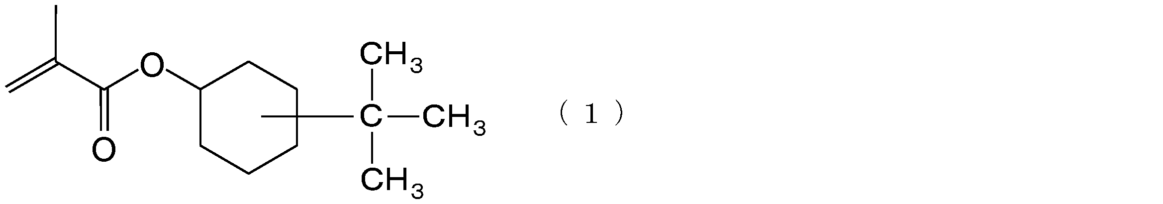

本実施形態に係る樹脂材料は、メチルメタクリレート20~90質量%と、下記式(1)で表されるtert-ブチルシクロヘキシルメタクリレート10~70質量%と、これら以外のモノマー(a)0~20質量%との共重合体を含有する。

本実施形態に係る光学フィルムは、上記樹脂材料からなるフィルムである。
Re=(nx-ny)×d (nm) …(2)
Rth=((nx+ny)/2-nz)×d (nm) …(3)
C=ΔRe/(Δσ×t) …(4)
本実施形態に係る画像表示装置は、上記光学フィルムを備える。上記光学フィルムは、配向複屈折及び光弾性複屈折がともに小さいため、像質の悪化を十分に防止することができる。そのため、このような画像表示装置によれば、良好な像質が実現される。画像表示装置は、例えば、上記光学フィルムを張り合わせた偏光板を備えるものであってよい。
上述の懸濁重合法により、メチルメタクリレート70質量%及び4-tert-ブチルシクロヘキシルメタクリレート30質量%を共重合して、粒子状のポリマー(以下、場合により「ポリマー(A-1)」という。)を得た。得られたポリマー(A-1)の重量平均分子量をゲル浸透クロマトグラフィーで測定した結果、1.8×10⁵であった。また、ガラス転移温度を示差走査熱量測定により測定した結果、130℃であった。
Tp=5(Tg+70)/4 …(5)
上述の懸濁重合法により、メチルメタクリレート60質量%及び4-tert-ブチルシクロヘキシルメタクリレート40質量%を共重合して、粒子状のポリマー(以下、場合により「ポリマー(A-2)」という。)を得た。得られたポリマー(A-2)の重量平均分子量をゲル浸透クロマトグラフィーで測定した結果、1.8×10⁵であった。また、ガラス転移温度を示差走査熱量測定により測定した結果、135℃であった。
フィルムの延伸倍率を、搬送方向、幅方向ともに2.2倍(-)とし、フィルムの面積比が4.84倍となるように延伸したこと以外は、実施例2と同じ方法で、ポリマー(A-2)を用いた光学フィルムを製造した。
上述の懸濁重合法により、メチルメタクリレート50質量%及び4-tert-ブチルシクロヘキシルメタクリレート50質量%を共重合して、粒子状のポリマー(以下、場合により「ポリマー(A-3)」という。)を得た。得られたポリマー(A-3)の重量平均分子量をゲル浸透クロマトグラフィーで測定した結果、1.8×10⁵であった。また、ガラス転移温度を示差走査熱量測定により測定した結果、140℃であった。
フィルムの延伸倍率を、搬送方向、幅方向ともに2.4倍(-)とし、フィルムの面積比が5.76倍となるように延伸したこと以外は、実施例4と同じ方法で、ポリマー(A-3)を用いた光学フィルムを製造した。
上述の懸濁重合法により、メチルメタクリレート40質量%及び4-tert-ブチルシクロヘキシルメタクリレート60質量%を共重合して、粒子状のポリマー(以下、場合により「ポリマー(A-4)」という。)を得た。得られたポリマー(A-4)の重量平均分子量をゲル浸透クロマトグラフィーで測定した結果、1.8×10⁵であった。また、ガラス転移温度を示差走査熱量測定により測定した結果、145℃であった。
フィルムの延伸倍率を、搬送方向、幅方向ともに2.4倍(-)とし、フィルムの面積比が5.76倍となるように延伸したこと以外は、実施例6と同じ方法で、ポリマー(A-4)を用いた光学フィルムを製造した。
上述の懸濁重合法により、メチルメタクリレート30質量%及び4-tert-ブチルシクロヘキシルメタクリレート70質量%を共重合して、粒子状のポリマー(以下、場合により「ポリマー(A-5)」という。)を得た。得られたポリマー(A-5)の重量平均分子量をゲル浸透クロマトグラフィーで測定した結果、1.8×10⁵であった。また、ガラス転移温度を示差走査熱量測定により測定した結果、150℃であった。
上述の懸濁重合法により、メチルメタクリレート85質量%、4-tert-ブチルシクロヘキシルメタクリレート10質量%及びフェノキシエチルアクリレート5質量%を共重合して、粒子状のポリマー(以下、場合により「ポリマー(A-6)」という。)を得た。得られたポリマー(A-6)の重量平均分子量をゲル浸透クロマトグラフィーで測定した結果、1.8×10⁵であった。また、ガラス転移温度を示差走査熱量測定により測定した結果、108℃であった。
フィルムの延伸倍率を、搬送方向、幅方向ともに2.4倍(-)とし、フィルムの面積比が5.76倍となるように延伸したこと以外は、実施例9と同じ方法で、ポリマー(A-6)を用いた光学フィルムを製造した。
上述の懸濁重合法により、メチルメタクリレート75質量%、4-tert-ブチルシクロヘキシルメタクリレート20質量%及びフェノキシエチルアクリレート5質量%を共重合して、粒子状のポリマー(以下、場合により「ポリマー(A-7)」という。)を得た。得られたポリマー(A-7)の重量平均分子量をゲル浸透クロマトグラフィーで測定した結果、1.8×10⁵であった。また、ガラス転移温度を示差走査熱量測定により測定した結果、120℃であった。
上述の懸濁重合法により、メチルメタクリレート70質量%、4-tert-ブチルシクロヘキシルメタクリレート20質量%及びフェノキシエチルアクリレート10質量%を共重合して、粒子状のポリマー(以下、場合により「ポリマー(A-8)」という。)を得た。得られたポリマー(A-8)の重量平均分子量をゲル浸透クロマトグラフィーで測定した結果、1.8×10⁵であった。また、ガラス転移温度を示差走査熱量測定により測定した結果、107℃であった。
上述の懸濁重合法により、メチルメタクリレート25質量%、4-tert-ブチルシクロヘキシルメタクリレート70質量%及びメチルアクリレート5質量%を共重合して、粒子状のポリマー(以下、場合により「ポリマー(A-9)」という。)を得た。得られたポリマー(A-9)の重量平均分子量をゲル浸透クロマトグラフィーで測定した結果、1.8×10⁵であった。また、ガラス転移温度を示差走査熱量測定により測定した結果、145℃であった。
フィルムの延伸倍率を、搬送方向、幅方向ともに2.4倍(-)とし、フィルムの面積比が5.76倍となるように延伸したこと以外は、実施例13と同じ方法で、ポリマー(A-9)を用いた光学フィルムを製造した。
上述の懸濁重合法により、メチルメタクリレート20質量%、4-tert-ブチルシクロヘキシルメタクリレート60質量%及びメチルアクリレート20質量%を共重合して、粒子状のポリマー(以下、場合により「ポリマー(A-10)」という。)を得た。得られたポリマー(A-10)の重量平均分子量をゲル浸透クロマトグラフィーで測定した結果、1.8×10⁵であった。また、ガラス転移温度を示差走査熱量測定により測定した結果、120℃であった。
フィルムの延伸倍率を、搬送方向、幅方向ともに2.4倍(-)とし、フィルムの面積比が5.76倍となるように延伸したこと以外は、実施例15と同じ方法で、ポリマー(A-10)を用いた光学フィルムを製造した。
上述の懸濁重合法により、メチルメタクリレート100質量%からなる粒子状のポリマー(以下、場合により「ポリマー(B-1)」という。)を得た。得られたポリマー(B-1)の重量平均分子量をゲル浸透クロマトグラフィーで測定した結果、1.8×10⁵であった。また、ガラス転移温度を示差走査熱量測定により測定した結果、105℃であった。
フィルムの延伸倍率を、搬送方向、幅方向ともに2.2倍(-)とし、フィルムの面積比が4.84倍となるように延伸したこと以外は、比較例1と同じ方法で、ポリマー(B-1)を用いた光学フィルムを製造した。
上述の懸濁重合法により、メチルメタクリレート91質量%及び4-tert-ブチルシクロヘキシルメタクリレート9質量%を共重合して、粒子状のポリマー(以下、場合により「ポリマー(B-2)」という。)を得た。得られたポリマー(B-2)の重量平均分子量をゲル浸透クロマトグラフィーで測定した結果、1.8×10⁵であった。また、ガラス転移温度を示差走査熱量測定により測定した結果、109℃であった。
上述の懸濁重合法により、メチルメタクリレート86質量%、4-tert-ブチルシクロヘキシルメタクリレート9質量%及びフェノキシエチルアクリレート5質量%を共重合して、粒子状のポリマー(以下、場合により「ポリマー(B-3)」という。)を得た。得られたポリマー(B-3)の重量平均分子量をゲル浸透クロマトグラフィーで測定した結果、1.8×10⁵であった。また、ガラス転移温度を示差走査熱量測定により測定した結果、103℃であった。
上述の懸濁重合法により、メチルメタクリレート86質量%、4-tert-ブチルシクロヘキシルメタクリレート9質量%及びメチルアクリレート5質量%を共重合して、粒子状のポリマー(以下、場合により「ポリマー(B-4)」という。)を得た。得られたポリマー(B-4)の重量平均分子量をゲル浸透クロマトグラフィーで測定した結果、1.8×10⁵であった。また、ガラス転移温度を示差走査熱量測定により測定した結果、104℃であった。
上述の懸濁重合法により、メチルメタクリレート25質量%及び4-tert-ブチルシクロヘキシルメタクリレート75質量%を共重合して、粒子状のポリマー(以下、場合により「ポリマー(B-5)」という。)を得た。得られたポリマー(B-5)の重量平均分子量をゲル浸透クロマトグラフィーで測定した結果、1.8×10⁵であった。また、ガラス転移温度を示差走査熱量測定により測定した結果、153℃であった。
上述の懸濁重合法により、メチルメタクリレート20質量%、4-tert-ブチルシクロヘキシルメタクリレート75質量%及びメチルアクリレート5質量%を共重合して、粒子状のポリマー(以下、場合により「ポリマー(B-6)」という。)を得た。得られたポリマー(B-6)の重量平均分子量をゲル浸透クロマトグラフィーで測定した結果、1.8×10⁵であった。また、ガラス転移温度を示差走査熱量測定により測定した結果、150℃であった。
上述の懸濁重合法により、メチルメタクリレート5質量%、4-tert-ブチルシクロヘキシルメタクリレート75質量%及びメチルアクリレート20質量%を共重合して、粒子状のポリマー(以下、場合により「ポリマー(B-7)」という。)を得た。得られたポリマー(B-7)の重量平均分子量をゲル浸透クロマトグラフィーで測定した結果、1.8×10⁵であった。また、ガラス転移温度を示差走査熱量測定により測定した結果、140℃であった。
上述の懸濁重合法により、メチルメタクリレート20質量%、4-tert-ブチルシクロヘキシルメタクリレート75質量%及びフェノキシエチルアクリレート5質量%を共重合して、粒子状のポリマー(以下、場合により「ポリマー(B-8)」という。)を得た。得られたポリマー(B-8)の重量平均分子量をゲル浸透クロマトグラフィーで測定した結果、1.8×10⁵であった。また、ガラス転移温度を示差走査熱量測定により測定した結果、149℃であった。
上述の懸濁重合法により、メチルメタクリレート90質量%及びフェノキシエチルアクリレート10質量%を共重合して、粒子状のポリマー(以下、場合により「ポリマー(B-9)」という。)を得た。得られたポリマー(B-9)の重量平均分子量をゲル浸透クロマトグラフィーで測定した結果、1.8×10⁵であった。また、ガラス転移温度を示差走査熱量測定により測定した結果、93℃であった。
実施例1で使用した粒子状のポリマー(A-1)を、実施例1と同様の方法でフィルムとした。このとき、フィルムの延伸倍率は、搬送方向、幅方向ともに1.1倍(-)とし、フィルムの面積比が1.21倍となるように延伸した。
実施例6で使用した粒子状のポリマー(A-4)を、実施例1と同様の方法でフィルムとした。このとき、フィルムの延伸倍率は、搬送方向、幅方向ともに2.5倍(-)とし、フィルムの面積比が6.25倍となるように延伸した。


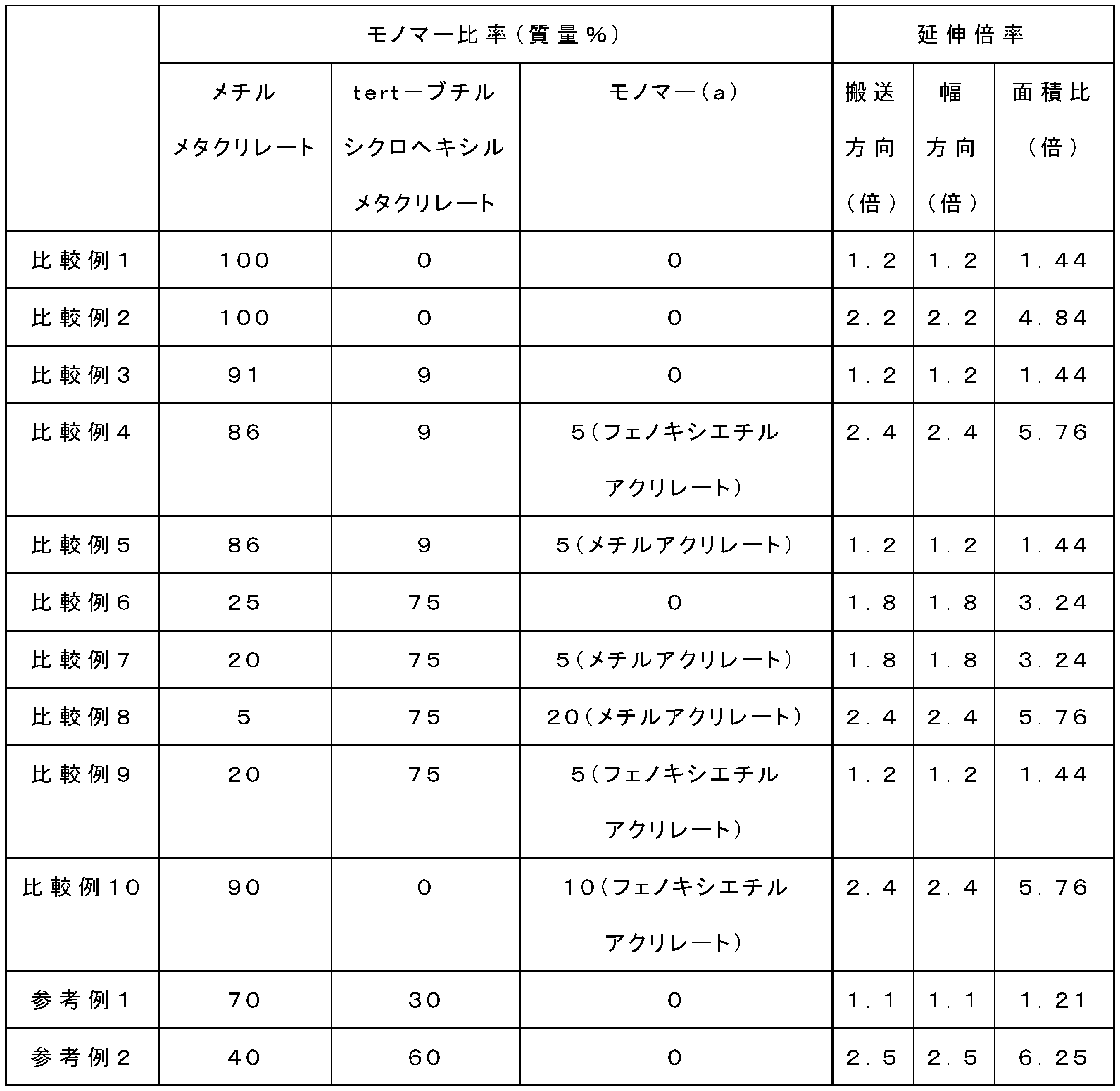
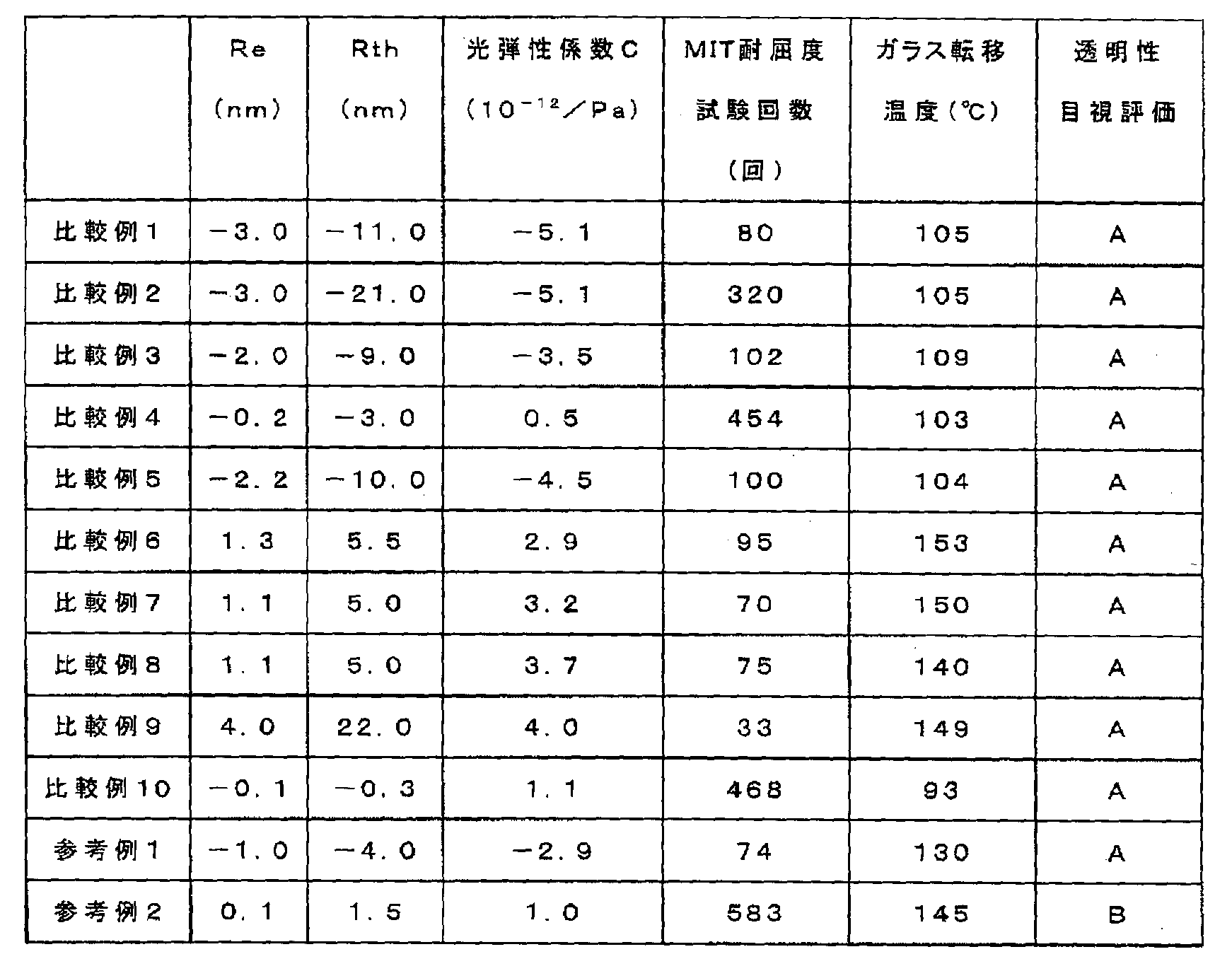
Claims (7)
- メチルメタクリレート20~90質量%と、下記式(1)で表されるtert-ブチルシクロヘキシルメタクリレート10~70質量%と、前記メチルメタクリレート及び前記tert-ブチルシクロヘキシルメタクリレート以外のモノマー0~20質量%との共重合体を含有する樹脂材料からなり、
前記樹脂材料を溶融押出して成形された未延伸フィルムを、面積比で1.4~6.0倍に延伸してなる、光学フィルム。

- メチルメタクリレート20~90質量%と、下記式(1)で表されるtert-ブチルシクロヘキシルメタクリレート10~70質量%と、前記メチルメタクリレート及び前記tert-ブチルシクロヘキシルメタクリレート以外のモノマー0~20質量%との共重合体を含有する樹脂材料からなり、
面内位相差値Reの絶対値及び厚み方向位相差値Rthの絶対値がいずれも5.0nm以下であり、
光弾性係数の絶対値が5.0×10⁻¹²(/Pa)以下である、光学フィルム。

- 前記樹脂材料のガラス転移温度が105℃以上である、請求項2に記載の光学フィルム。
- JIS P8115に準拠したMIT耐屈度試験回数が100回以上である、請求項2又は3に記載の光学フィルム。
- メチルメタクリレート20~90質量%と、下記式(1)で表されるtert-ブチルシクロヘキシルメタクリレート10~70質量%と、前記メチルメタクリレート及び前記tert-ブチルシクロヘキシルメタクリレート以外のモノマー0~20質量%との共重合体を含有する、光学フィルム用樹脂材料。

- 請求項5に記載の光学フィルム用樹脂材料を溶融押出して未延伸フィルムを得る溶融押出工程と、前記未延伸フィルムを面積比で1.4~6.0倍に延伸して光学フィルムを得る延伸工程と、を備える、光学フィルムの製造方法。
- 請求項1~4のいずれか一項に記載の光学フィルムを備える、画像表示装置。
Priority Applications (4)
| Application Number | Priority Date | Filing Date | Title |
|---|---|---|---|
| KR1020147017538A KR20140099511A (ko) | 2011-11-30 | 2012-09-25 | 광학 필름, 광학 필름용 수지 재료 및 화상 표시 장치 |
| US14/361,890 US20140309395A1 (en) | 2011-11-30 | 2012-09-25 | Optical film, resin material for optical film, and image display device |
| CN201280058964.0A CN104011097A (zh) | 2011-11-30 | 2012-09-25 | 光学膜、光学膜用树脂材料和图像显示装置 |
| EP12853145.6A EP2789634A4 (en) | 2011-11-30 | 2012-09-25 | OPTICAL FILM, RESIN MATERIAL FOR AN OPTICAL FILM AND IMAGE DISPLAY DEVICE |
Applications Claiming Priority (2)
| Application Number | Priority Date | Filing Date | Title |
|---|---|---|---|
| JP2011262426A JP2013114198A (ja) | 2011-11-30 | 2011-11-30 | 光学フィルム、光学フィルム用樹脂材料及び画像表示装置 |
| JP2011-262426 | 2011-11-30 |
Publications (1)
| Publication Number | Publication Date |
|---|---|
| WO2013080642A1 true WO2013080642A1 (ja) | 2013-06-06 |
Family
ID=48535117
Family Applications (1)
| Application Number | Title | Priority Date | Filing Date |
|---|---|---|---|
| PCT/JP2012/074539 WO2013080642A1 (ja) | 2011-11-30 | 2012-09-25 | 光学フィルム、光学フィルム用樹脂材料及び画像表示装置 |
Country Status (7)
| Country | Link |
|---|---|
| US (1) | US20140309395A1 (ja) |
| EP (1) | EP2789634A4 (ja) |
| JP (1) | JP2013114198A (ja) |
| KR (1) | KR20140099511A (ja) |
| CN (1) | CN104011097A (ja) |
| TW (1) | TW201326290A (ja) |
| WO (1) | WO2013080642A1 (ja) |
Cited By (1)
| Publication number | Priority date | Publication date | Assignee | Title |
|---|---|---|---|---|
| WO2014203637A1 (ja) * | 2013-06-17 | 2014-12-24 | コニカミノルタ株式会社 | 偏光板及び液晶表示装置 |
Families Citing this family (11)
| Publication number | Priority date | Publication date | Assignee | Title |
|---|---|---|---|---|
| JP6313674B2 (ja) * | 2013-07-05 | 2018-04-18 | 富士フイルム株式会社 | 偏光板および液晶表示装置 |
| JP2015125241A (ja) * | 2013-12-26 | 2015-07-06 | エルジー ディスプレイ カンパニー リミテッド | 液晶表示装置 |
| TWI718244B (zh) * | 2016-02-05 | 2021-02-11 | 日商三菱瓦斯化學股份有限公司 | 熱可塑性樹脂層合延伸薄膜 |
| TWI770005B (zh) * | 2016-02-05 | 2022-07-11 | 日商三菱瓦斯化學股份有限公司 | 熱可塑性樹脂層合延伸薄膜 |
| KR101889078B1 (ko) | 2016-06-22 | 2018-08-16 | 주식회사 엘지화학 | 광학용 필름 및 이를 포함하는 편광판 |
| WO2018173762A1 (ja) * | 2017-03-22 | 2018-09-27 | 三菱瓦斯化学株式会社 | 熱可塑性樹脂積層延伸フィルム |
| JP7251724B2 (ja) | 2017-12-28 | 2023-04-04 | Kjケミカルズ株式会社 | t-ブチルシクロヘキシル(メタ)アクリレートを用いた重合性樹脂組成物 |
| US20220177622A1 (en) * | 2019-04-04 | 2022-06-09 | Trinseo Europe Gmbh | Impact resistant hydrophobic high heat optical acrylic copolymers |
| CN114222768A (zh) * | 2019-04-04 | 2022-03-22 | 盛禧奥欧洲有限责任公司 | 疏水性高热光学丙烯酸系共聚物 |
| US11891466B2 (en) | 2022-03-04 | 2024-02-06 | Trinseo Europe Gmbh | Heat resistant PMMA copolymers having high temperature and high humidity environmental stability for electronic component applications |
| US20230279212A1 (en) * | 2022-03-04 | 2023-09-07 | Trinseo Europe Gmbh | Acrylic copolymer resins |
Citations (11)
| Publication number | Priority date | Publication date | Assignee | Title |
|---|---|---|---|---|
| JPS6317915A (ja) * | 1986-07-09 | 1988-01-25 | Asahi Chem Ind Co Ltd | 低吸湿性メタクリル系樹脂の製造方法 |
| JPS6317401A (ja) * | 1986-07-10 | 1988-01-25 | Asahi Chem Ind Co Ltd | メタクリル系樹脂を基板材料とする光学式情報記録用デイスク |
| JPH02233710A (ja) * | 1989-03-08 | 1990-09-17 | Asahi Chem Ind Co Ltd | 低吸湿性メタクリル系樹脂 |
| JP2001233912A (ja) | 2000-02-23 | 2001-08-28 | Mitsubishi Rayon Co Ltd | メタクリル系重合体の製造方法 |
| WO2007026659A1 (ja) * | 2005-08-30 | 2007-03-08 | Nitto Denko Corporation | 偏光子保護フィルム、偏光板、および画像表示装置 |
| JP2007100044A (ja) | 2005-10-07 | 2007-04-19 | Nippon Shokubai Co Ltd | アクリル系透明性フィルム又はシート |
| JP2008255149A (ja) | 2007-04-02 | 2008-10-23 | Asahi Kasei Chemicals Corp | 光学材料用樹脂組成物 |
| JP2009052036A (ja) * | 2007-07-30 | 2009-03-12 | Toray Ind Inc | アクリル系フィルム、積層フィルムおよび偏光板 |
| JP2009053492A (ja) * | 2007-08-28 | 2009-03-12 | Toray Ind Inc | 積層フィルムおよび光学補償層付き偏光板 |
| JP2009292869A (ja) | 2008-06-02 | 2009-12-17 | Fujifilm Corp | アクリルフィルム、その製造方法、偏光板、光学補償フィルム、反射防止フィルムおよび液晶表示装置 |
| JP2010072135A (ja) * | 2008-09-17 | 2010-04-02 | Nippon Shokubai Co Ltd | 光学フィルム |
Family Cites Families (5)
| Publication number | Priority date | Publication date | Assignee | Title |
|---|---|---|---|---|
| JPS61254608A (ja) * | 1985-05-02 | 1986-11-12 | Sumitomo Chem Co Ltd | 耐熱変形性の優れた熱可塑性共重合体の製造方法 |
| KR100948778B1 (ko) * | 2007-01-23 | 2010-03-24 | 주식회사 엘지화학 | 광학 보상된 아크릴계 점착제 조성물, 이를 포함하는편광판 및 액정표시소자 |
| JP2008299096A (ja) * | 2007-05-31 | 2008-12-11 | Nippon Shokubai Co Ltd | 偏光子保護フィルム、偏光板、および液晶表示装置 |
| KR20090076754A (ko) * | 2008-01-08 | 2009-07-13 | 주식회사 엘지화학 | 광학 필름, 위상차 필름, 보호 필름 및 이들을 포함하는액정 표시 장치 |
| CN102317333B (zh) * | 2009-02-18 | 2015-06-10 | Lg化学株式会社 | 丙烯酸类树脂组合物和包含该丙烯酸类树脂组合物的光学膜 |
-
2011
- 2011-11-30 JP JP2011262426A patent/JP2013114198A/ja active Pending
-
2012
- 2012-09-25 CN CN201280058964.0A patent/CN104011097A/zh active Pending
- 2012-09-25 EP EP12853145.6A patent/EP2789634A4/en not_active Withdrawn
- 2012-09-25 WO PCT/JP2012/074539 patent/WO2013080642A1/ja active Application Filing
- 2012-09-25 KR KR1020147017538A patent/KR20140099511A/ko not_active Application Discontinuation
- 2012-09-25 US US14/361,890 patent/US20140309395A1/en not_active Abandoned
- 2012-11-22 TW TW101143805A patent/TW201326290A/zh unknown
Patent Citations (11)
| Publication number | Priority date | Publication date | Assignee | Title |
|---|---|---|---|---|
| JPS6317915A (ja) * | 1986-07-09 | 1988-01-25 | Asahi Chem Ind Co Ltd | 低吸湿性メタクリル系樹脂の製造方法 |
| JPS6317401A (ja) * | 1986-07-10 | 1988-01-25 | Asahi Chem Ind Co Ltd | メタクリル系樹脂を基板材料とする光学式情報記録用デイスク |
| JPH02233710A (ja) * | 1989-03-08 | 1990-09-17 | Asahi Chem Ind Co Ltd | 低吸湿性メタクリル系樹脂 |
| JP2001233912A (ja) | 2000-02-23 | 2001-08-28 | Mitsubishi Rayon Co Ltd | メタクリル系重合体の製造方法 |
| WO2007026659A1 (ja) * | 2005-08-30 | 2007-03-08 | Nitto Denko Corporation | 偏光子保護フィルム、偏光板、および画像表示装置 |
| JP2007100044A (ja) | 2005-10-07 | 2007-04-19 | Nippon Shokubai Co Ltd | アクリル系透明性フィルム又はシート |
| JP2008255149A (ja) | 2007-04-02 | 2008-10-23 | Asahi Kasei Chemicals Corp | 光学材料用樹脂組成物 |
| JP2009052036A (ja) * | 2007-07-30 | 2009-03-12 | Toray Ind Inc | アクリル系フィルム、積層フィルムおよび偏光板 |
| JP2009053492A (ja) * | 2007-08-28 | 2009-03-12 | Toray Ind Inc | 積層フィルムおよび光学補償層付き偏光板 |
| JP2009292869A (ja) | 2008-06-02 | 2009-12-17 | Fujifilm Corp | アクリルフィルム、その製造方法、偏光板、光学補償フィルム、反射防止フィルムおよび液晶表示装置 |
| JP2010072135A (ja) * | 2008-09-17 | 2010-04-02 | Nippon Shokubai Co Ltd | 光学フィルム |
Non-Patent Citations (1)
| Title |
|---|
| See also references of EP2789634A4 * |
Cited By (1)
| Publication number | Priority date | Publication date | Assignee | Title |
|---|---|---|---|---|
| WO2014203637A1 (ja) * | 2013-06-17 | 2014-12-24 | コニカミノルタ株式会社 | 偏光板及び液晶表示装置 |
Also Published As
| Publication number | Publication date |
|---|---|
| TW201326290A (zh) | 2013-07-01 |
| CN104011097A (zh) | 2014-08-27 |
| KR20140099511A (ko) | 2014-08-12 |
| EP2789634A4 (en) | 2015-08-05 |
| JP2013114198A (ja) | 2013-06-10 |
| EP2789634A1 (en) | 2014-10-15 |
| US20140309395A1 (en) | 2014-10-16 |
Similar Documents
| Publication | Publication Date | Title |
|---|---|---|
| WO2013080642A1 (ja) | 光学フィルム、光学フィルム用樹脂材料及び画像表示装置 | |
| JP5758530B2 (ja) | アクリル系共重合体、光学フィルム、偏光板および液晶表示装置 | |
| JP4697098B2 (ja) | 位相差フィルム | |
| JP4686261B2 (ja) | 偏光子保護フィルムおよびその製造方法、ならびにそれを用いた偏光板 | |
| KR102086326B1 (ko) | 푸마르산디이소프로필-계피산 유도체계 공중합체 및 그것을 사용한 위상차 필름 | |
| KR20130100920A (ko) | 위상차 필름용 푸마르산 디에스테르계 수지 및 그것으로 이루어지는 위상차 필름 | |
| JP5535167B2 (ja) | 光学フィルム及びそれを備える液晶表示装置 | |
| JP2006162748A (ja) | 偏光子保護フィルムおよび偏光板 | |
| JP2012082358A (ja) | 光学用フィルム | |
| WO2013021872A1 (ja) | 光学樹脂材料及び光学樹脂材料の製造方法 | |
| JP5697784B2 (ja) | アクリル系共重合体、二軸延伸フィルム、偏光板および液晶表示装置 | |
| JP5965612B2 (ja) | 光学フィルム及びその製造方法 | |
| JP2006133328A (ja) | 位相差フィルム一体型偏光板 | |
| JP2014133883A (ja) | アクリル系共重合体、光学フィルム、偏光板及び液晶表示装置 | |
| JP2014111751A (ja) | アクリル系共重合体、光学フィルム、偏光板および液晶表示装置 | |
| KR101304589B1 (ko) | 투명성, 인성 및 내열성이 우수한 광학 필름용 조성물 및 이를 포함하는 광학 필름 | |
| KR102084114B1 (ko) | 광학필름, 이를 포함하는 편광판 및 이를 포함하는 액정표시장치 | |
| JP2011137862A (ja) | 光学補償フィルム | |
| JP2014133885A (ja) | アクリル系共重合体、光学フィルム、偏光板及び液晶表示装置 | |
| JP5440108B2 (ja) | 光学補償フィルム | |
| JP2014002419A (ja) | 光学補償フィルム | |
| WO2014184950A1 (ja) | 光学フィルムおよび画像表示装置 | |
| JP2014111750A (ja) | アクリル系共重合体、光学フィルム、偏光板および液晶表示装置 | |
| JP2014133884A (ja) | アクリル系共重合体、光学フィルム、偏光板及び液晶表示装置 | |
| JP2014133882A (ja) | アクリル系共重合体、光学フィルム、偏光板及び液晶表示装置 |
Legal Events
| Date | Code | Title | Description |
|---|---|---|---|
| 121 | Ep: the epo has been informed by wipo that ep was designated in this application |
Ref document number: 12853145 Country of ref document: EP Kind code of ref document: A1 |
|
| NENP | Non-entry into the national phase |
Ref country code: DE |
|
| WWE | Wipo information: entry into national phase |
Ref document number: 14361890 Country of ref document: US |
|
| WWE | Wipo information: entry into national phase |
Ref document number: 2012853145 Country of ref document: EP |
|
| ENP | Entry into the national phase |
Ref document number: 20147017538 Country of ref document: KR Kind code of ref document: A |