WO2013073701A1 - 照明装置、車両用前照灯、およびダウンライト - Google Patents
照明装置、車両用前照灯、およびダウンライト Download PDFInfo
- Publication number
- WO2013073701A1 WO2013073701A1 PCT/JP2012/079990 JP2012079990W WO2013073701A1 WO 2013073701 A1 WO2013073701 A1 WO 2013073701A1 JP 2012079990 W JP2012079990 W JP 2012079990W WO 2013073701 A1 WO2013073701 A1 WO 2013073701A1
- Authority
- WO
- WIPO (PCT)
- Prior art keywords
- light
- laser
- light emitting
- emitting unit
- laser light
- Prior art date
- Legal status (The legal status is an assumption and is not a legal conclusion. Google has not performed a legal analysis and makes no representation as to the accuracy of the status listed.)
- Ceased
Links
Images







Classifications
-
- F—MECHANICAL ENGINEERING; LIGHTING; HEATING; WEAPONS; BLASTING
- F21—LIGHTING
- F21S—NON-PORTABLE LIGHTING DEVICES; SYSTEMS THEREOF; VEHICLE LIGHTING DEVICES SPECIALLY ADAPTED FOR VEHICLE EXTERIORS
- F21S41/00—Illuminating devices specially adapted for vehicle exteriors, e.g. headlamps
- F21S41/10—Illuminating devices specially adapted for vehicle exteriors, e.g. headlamps characterised by the light source
- F21S41/14—Illuminating devices specially adapted for vehicle exteriors, e.g. headlamps characterised by the light source characterised by the type of light source
- F21S41/16—Laser light sources
-
- F—MECHANICAL ENGINEERING; LIGHTING; HEATING; WEAPONS; BLASTING
- F21—LIGHTING
- F21S—NON-PORTABLE LIGHTING DEVICES; SYSTEMS THEREOF; VEHICLE LIGHTING DEVICES SPECIALLY ADAPTED FOR VEHICLE EXTERIORS
- F21S41/00—Illuminating devices specially adapted for vehicle exteriors, e.g. headlamps
- F21S41/10—Illuminating devices specially adapted for vehicle exteriors, e.g. headlamps characterised by the light source
- F21S41/12—Illuminating devices specially adapted for vehicle exteriors, e.g. headlamps characterised by the light source characterised by the type of emitted light
-
- F—MECHANICAL ENGINEERING; LIGHTING; HEATING; WEAPONS; BLASTING
- F21—LIGHTING
- F21S—NON-PORTABLE LIGHTING DEVICES; SYSTEMS THEREOF; VEHICLE LIGHTING DEVICES SPECIALLY ADAPTED FOR VEHICLE EXTERIORS
- F21S41/00—Illuminating devices specially adapted for vehicle exteriors, e.g. headlamps
- F21S41/10—Illuminating devices specially adapted for vehicle exteriors, e.g. headlamps characterised by the light source
- F21S41/14—Illuminating devices specially adapted for vehicle exteriors, e.g. headlamps characterised by the light source characterised by the type of light source
- F21S41/176—Light sources where the light is generated by photoluminescent material spaced from a primary light generating element
-
- F—MECHANICAL ENGINEERING; LIGHTING; HEATING; WEAPONS; BLASTING
- F21—LIGHTING
- F21S—NON-PORTABLE LIGHTING DEVICES; SYSTEMS THEREOF; VEHICLE LIGHTING DEVICES SPECIALLY ADAPTED FOR VEHICLE EXTERIORS
- F21S8/00—Lighting devices intended for fixed installation
- F21S8/04—Lighting devices intended for fixed installation intended only for mounting on a ceiling or the like overhead structures
-
- F—MECHANICAL ENGINEERING; LIGHTING; HEATING; WEAPONS; BLASTING
- F21—LIGHTING
- F21V—FUNCTIONAL FEATURES OR DETAILS OF LIGHTING DEVICES OR SYSTEMS THEREOF; STRUCTURAL COMBINATIONS OF LIGHTING DEVICES WITH OTHER ARTICLES, NOT OTHERWISE PROVIDED FOR
- F21V29/00—Protecting lighting devices from thermal damage; Cooling or heating arrangements specially adapted for lighting devices or systems
- F21V29/50—Cooling arrangements
- F21V29/502—Cooling arrangements characterised by the adaptation for cooling of specific components
- F21V29/506—Cooling arrangements characterised by the adaptation for cooling of specific components of globes, bowls or cover glasses
-
- F—MECHANICAL ENGINEERING; LIGHTING; HEATING; WEAPONS; BLASTING
- F21—LIGHTING
- F21V—FUNCTIONAL FEATURES OR DETAILS OF LIGHTING DEVICES OR SYSTEMS THEREOF; STRUCTURAL COMBINATIONS OF LIGHTING DEVICES WITH OTHER ARTICLES, NOT OTHERWISE PROVIDED FOR
- F21V9/00—Elements for modifying spectral properties, polarisation or intensity of the light emitted, e.g. filters
- F21V9/30—Elements containing photoluminescent material distinct from or spaced from the light source
-
- H—ELECTRICITY
- H01—ELECTRIC ELEMENTS
- H01S—DEVICES USING THE PROCESS OF LIGHT AMPLIFICATION BY STIMULATED EMISSION OF RADIATION [LASER] TO AMPLIFY OR GENERATE LIGHT; DEVICES USING STIMULATED EMISSION OF ELECTROMAGNETIC RADIATION IN WAVE RANGES OTHER THAN OPTICAL
- H01S5/00—Semiconductor lasers
- H01S5/02—Structural details or components not essential to laser action
- H01S5/022—Mountings; Housings
- H01S5/0225—Out-coupling of light
- H01S5/02251—Out-coupling of light using optical fibres
-
- H—ELECTRICITY
- H01—ELECTRIC ELEMENTS
- H01S—DEVICES USING THE PROCESS OF LIGHT AMPLIFICATION BY STIMULATED EMISSION OF RADIATION [LASER] TO AMPLIFY OR GENERATE LIGHT; DEVICES USING STIMULATED EMISSION OF ELECTROMAGNETIC RADIATION IN WAVE RANGES OTHER THAN OPTICAL
- H01S5/00—Semiconductor lasers
- H01S5/30—Structure or shape of the active region; Materials used for the active region
- H01S5/3013—AIIIBV compounds
-
- F—MECHANICAL ENGINEERING; LIGHTING; HEATING; WEAPONS; BLASTING
- F21—LIGHTING
- F21S—NON-PORTABLE LIGHTING DEVICES; SYSTEMS THEREOF; VEHICLE LIGHTING DEVICES SPECIALLY ADAPTED FOR VEHICLE EXTERIORS
- F21S45/00—Arrangements within vehicle lighting devices specially adapted for vehicle exteriors, for purposes other than emission or distribution of light
- F21S45/40—Cooling of lighting devices
- F21S45/47—Passive cooling, e.g. using fins, thermal conductive elements or openings
-
- F—MECHANICAL ENGINEERING; LIGHTING; HEATING; WEAPONS; BLASTING
- F21—LIGHTING
- F21V—FUNCTIONAL FEATURES OR DETAILS OF LIGHTING DEVICES OR SYSTEMS THEREOF; STRUCTURAL COMBINATIONS OF LIGHTING DEVICES WITH OTHER ARTICLES, NOT OTHERWISE PROVIDED FOR
- F21V29/00—Protecting lighting devices from thermal damage; Cooling or heating arrangements specially adapted for lighting devices or systems
- F21V29/50—Cooling arrangements
- F21V29/502—Cooling arrangements characterised by the adaptation for cooling of specific components
- F21V29/505—Cooling arrangements characterised by the adaptation for cooling of specific components of reflectors
-
- F—MECHANICAL ENGINEERING; LIGHTING; HEATING; WEAPONS; BLASTING
- F21—LIGHTING
- F21V—FUNCTIONAL FEATURES OR DETAILS OF LIGHTING DEVICES OR SYSTEMS THEREOF; STRUCTURAL COMBINATIONS OF LIGHTING DEVICES WITH OTHER ARTICLES, NOT OTHERWISE PROVIDED FOR
- F21V33/00—Structural combinations of lighting devices with other articles, not otherwise provided for
- F21V33/006—General building constructions or finishing work for buildings, e.g. roofs, gutters, stairs or floors; Garden equipment; Sunshades or parasols
-
- F—MECHANICAL ENGINEERING; LIGHTING; HEATING; WEAPONS; BLASTING
- F21—LIGHTING
- F21V—FUNCTIONAL FEATURES OR DETAILS OF LIGHTING DEVICES OR SYSTEMS THEREOF; STRUCTURAL COMBINATIONS OF LIGHTING DEVICES WITH OTHER ARTICLES, NOT OTHERWISE PROVIDED FOR
- F21V7/00—Reflectors for light sources
- F21V7/04—Optical design
- F21V7/06—Optical design with parabolic curvature
-
- F—MECHANICAL ENGINEERING; LIGHTING; HEATING; WEAPONS; BLASTING
- F21—LIGHTING
- F21Y—INDEXING SCHEME ASSOCIATED WITH SUBCLASSES F21K, F21L, F21S and F21V, RELATING TO THE FORM OR THE KIND OF THE LIGHT SOURCES OR OF THE COLOUR OF THE LIGHT EMITTED
- F21Y2113/00—Combination of light sources
- F21Y2113/10—Combination of light sources of different colours
- F21Y2113/13—Combination of light sources of different colours comprising an assembly of point-like light sources
-
- F—MECHANICAL ENGINEERING; LIGHTING; HEATING; WEAPONS; BLASTING
- F21—LIGHTING
- F21Y—INDEXING SCHEME ASSOCIATED WITH SUBCLASSES F21K, F21L, F21S and F21V, RELATING TO THE FORM OR THE KIND OF THE LIGHT SOURCES OR OF THE COLOUR OF THE LIGHT EMITTED
- F21Y2115/00—Light-generating elements of semiconductor light sources
- F21Y2115/10—Light-emitting diodes [LED]
-
- F—MECHANICAL ENGINEERING; LIGHTING; HEATING; WEAPONS; BLASTING
- F21—LIGHTING
- F21Y—INDEXING SCHEME ASSOCIATED WITH SUBCLASSES F21K, F21L, F21S and F21V, RELATING TO THE FORM OR THE KIND OF THE LIGHT SOURCES OR OF THE COLOUR OF THE LIGHT EMITTED
- F21Y2115/00—Light-generating elements of semiconductor light sources
- F21Y2115/30—Semiconductor lasers
Definitions
- the present invention relates to an illuminating device, a vehicle headlamp, and a downlight that can irradiate illumination light having different chromaticities without changing the position of a light emitting point.
- LEDs Light Emitting Diodes
- LDs Laser Diodes
- Patent Document 1 is disclosed as an example of a technique related to such a light emitting device.
- the light-emitting device of Patent Document 1 uses a GaN-based semiconductor laser that emits a laser beam having a wavelength of 450 nm or less as an excitation light source, and combines a phosphor that emits fluorescence in the visible range when excited by the laser beam.
- the light-emitting device excites the phosphor with light having a short wavelength of 450 nm or less, such as blue light or ultraviolet light, thereby realizing high-luminance light emission.
- Japanese Patent Application Publication “JP 2000-174346 A (published on June 23, 2000)” Japanese Patent Application Publication “JP 2005-150041 A (published on June 9, 2005)” Japanese Patent Application Publication “JP 2004-354495 A (published on December 16, 2004)” Japanese Patent Application Publication “Japanese Unexamined Patent Application Publication No. 2012-121968 (Released on June 28, 2012)”
- the light control means is configured to change the outputs of at least two light sources having different chromaticities, and there are as many light emission points as the number of light sources. That is, there are a plurality of light emitting points. Therefore, when incorporating multiple light emitting points into an optical system such as a reflector or lens, a complicated optical design is required because the position of the light emitting point changes or there are multiple light emitting points, and high efficiency is achieved. In order to realize this optical system, there is a problem that the optical system needs to have a large size.
- Patent Documents 1 to 4 discloses or suggests a configuration in which the wavelengths emitted from a plurality of semiconductor lasers are different from each other.
- the present invention has been made to solve the above-described problems, and an object of the present invention is to provide an illumination device and a vehicle that can emit illumination light having different chromaticities without changing the position of the light emitting point. To provide headlights and downlights.
- an illumination device includes a plurality of laser light sources that emit laser light and a light-emitting unit that receives light to emit light, and the plurality of laser light sources includes Each of the plurality of laser light sources generates laser light at a plurality of wavelengths different from each other, and each of the plurality of laser light sources generates laser light having a wavelength capable of causing the light emitting unit to emit light.
- the laser light from a plurality of the laser light sources is irradiated.
- An illumination device includes a plurality of laser light sources that emit laser light and a light emitting unit that emits light upon receiving the light, and the plurality of laser light sources includes a plurality of different laser light sources.
- a laser beam is generated at a wavelength, and a laser beam having a wavelength that allows each of the light emitting units to emit light is generated, and laser light from a plurality of the laser light sources is irradiated to one light emitting unit. It is the composition which is done.
- FIG. 6 It is a figure explaining the other Example at the time of using the structure of FIG. 6 for a transmission type headlamp. It is a conceptual diagram which shows the arrangement
- the headlamp according to the present embodiment will be described with reference to the drawings.
- the headlamp is mainly described below, the headlamp is an example of a lighting device to which the present invention is applied, and it goes without saying that the present invention can be applied to any lighting device.
- the same parts and components are denoted by the same reference numerals. Their names and functions are also the same. Therefore, detailed description thereof will not be repeated.
- FIG. 1 is a cross-sectional view showing a schematic configuration of a headlamp (illumination device) 1 according to an embodiment of the present invention.
- the headlamp 1 includes a laser element (excitation light source) 2, a lens 3, a light emitting unit 4, a parabolic mirror 5, a metal base 7, and fins 8.
- the laser element 2 is a light emitting element that functions as an excitation light source that emits excitation light.
- a plurality of laser elements 2 are provided, and laser light as excitation light is oscillated from each of the plurality of laser elements 2.
- the laser element 2 may have one light emitting point on one chip, or may have a plurality of light emitting points on one chip.
- the laser element 2 includes a laser element 2a having a first oscillation wavelength and a laser element 2b having a second oscillation wavelength (when the laser element 2a and the laser element 2b are not distinguished from each other) It may be simply referred to as laser element 2).
- the laser element 2a has an oscillation wavelength in a blue-violet region near 405 nm, or in a violet-blue-violet region from 400 nm to 420 nm.
- the laser element 2b has an oscillation wavelength in a region greater than 450 nm and less than 530 nm.
- the headlamp 1 irradiates one light emitting unit 4 using the laser element 2a and the laser element 2b.
- the light emitting unit 4 includes a phosphor that emits fluorescence in response to excitation light emitted from the laser element 2, and the laser light from the laser element 2 and the fluorescence from the phosphor are mixed to obtain illumination light.
- each of the laser element 2a and the laser element 2b can be changed.
- the laser element 2a and the laser element 2b may not be configured to change their outputs, but one output may be fixed and the other output may be changed. According to this configuration, it is not necessary to adjust the output of at least the laser element whose output is fixed, and the number of laser elements for controlling the output can be reduced, so that the program used for the headlamp 1 is simplified. be able to.
- the headlamp 1 can reduce the time required to adjust the chromaticity to the desired illumination light, and can be reduced in size and weight by reducing the number of components.
- the laser elements 2a and 2b are described as having different oscillation wavelengths, but the oscillation wavelengths may be the same or very close. Further, the present invention is not limited to this configuration, but since the user can provide various chromaticity changes by increasing / decreasing the outputs of the two laser elements, both the laser element 2a and the laser element 2b have an output greater than zero. Is also preferably large.
- laser elements 2 may be used instead of a laser element as an excitation light source.
- the number of laser elements 2 is not limited to two and may be three or more.
- the laser element 2a and the laser element 2b may have the following relationship. That is, the laser element 2a and the laser element 2b include GaN, InN, and a mixed crystal compound thereof, and their oscillation wavelengths may be 400 nm or more and 420 nm or less, and the difference between the oscillation wavelengths may be 10 nm or less. .
- the power conversion efficiency of the laser element 2 can be increased. Therefore, the headlamp 1 can increase the luminous efficiency. Further, when the oscillation wavelength of the laser element 2 is in the range of 400 nm or more and 420 nm or less, there are many phosphors having high excitation efficiency with respect to light in this wavelength range, and in particular, phosphors that emit blue light are in this wavelength range. Excitation efficiency is high for light. For this reason, the total light emission efficiency of the headlamp 1 can be increased when the oscillation wavelength of the laser element 2 is in the range of not less than 400 nm and not more than 420 nm.
- the laser element 2a and the laser element 2b may have the following relationship. That is, the laser element 2a and the laser element 2b may each have an oscillation wavelength greater than 450 nm and 530 nm or less, and a difference between the oscillation wavelengths may be 10 nm or less.
- the headlamp 1 uses light emitted from the laser element 2 as a blue component in the illumination light emitted from itself. be able to. Further, by using a long wavelength blue in the blue region, according to JIS C6802 (safety standard of laser products), the safety of the laser light contained in the illumination light emitted from the headlamp 1 to the retina is increased. be able to. Therefore, the emission limit value that can realize eye-safe becomes higher than when the phosphor is excited using 450 nm laser light, and accordingly, the light output of the laser light that excites the phosphor can be set high. It becomes possible. Thereby, the headlamp 1 can emit higher-output illumination light.
- JIS C6802 safety standard of laser products
- the laser element 2a and the laser element 2b may have a difference in oscillation wavelength of 10 nm or less.
- the reason is as follows. That is, in order to make the oscillation wavelengths of the plurality of laser elements 2 the same, strict selection is required. Usually, since the oscillation wavelengths between the laser elements 2 are slightly different, it takes a lot of cost to prepare a plurality of semiconductor lasers having the same oscillation wavelength, and the yield is also lowered. Therefore, by setting the difference in oscillation wavelength to 10 nm or less, there is no need to strictly select the laser elements 2 in this way, the total cost can be suppressed, and the yield can be improved. Further, by setting the difference between the oscillation wavelengths to 10 nm or less, it is not necessary to strictly select the variation of the oscillation wavelength due to the manufacturing process while keeping the excitation efficiency for the phosphor high, and the defect loss can be suppressed low.
- FIG. 18A is a circuit diagram of the laser element 2
- FIG. 18B is a perspective view showing the basic structure of the laser element 2.
- the laser element 2 has a configuration in which a cathode electrode 19, a substrate 18, a clad layer 113, an active layer 111, a clad layer 112, and an anode electrode 17 are laminated in this order.
- the substrate 18 is a semiconductor substrate.
- compound semiconductors such as GaAs and GaN are used.
- a group IV semiconductor such as Si, Ge, and SiC, GaAs, GaP, InP, AlAs, GaN, and InN are used.
- GaN is used as the substrate 18.
- the anode electrode 17 is for injecting current into the active layer 111 through the clad layer 112.
- the cathode electrode 19 is for injecting current into the active layer 111 from the lower part of the substrate 18 through the clad layer 113.
- the current is injected by applying a forward bias to the anode electrode 17 and the cathode electrode 19.
- the active layer 111 has a structure sandwiched between the cladding layer 113 and the cladding layer 112.
- the material of the active layer 111 includes undoped GaAs, GaP, InP, AlAs, GaN, InN, InSb, GaSb, and AlN group III-V compound semiconductors, ZnTe, ZeSe, ZnS, ZnO, and the like. It may be composed of any of the II-VI compound semiconductors.
- GaN and InGaN are used.
- the active layer 111 is for confining light amplified by stimulated emission.
- the active layer 111 has a front side cleaved surface 114 and a back side cleaved surface 115 provided to face each other in order to confine light amplified by stimulated emission.
- the front side cleaved surface 114 and the back side cleaved surface 115 are formed. Plays the role of a mirror.
- the active layer 111 may form a multilayer quantum well structure.
- a reflective film (not shown) for laser oscillation is formed on the back side cleaved surface 115 opposite to the front side cleaved surface 114, and the difference in reflectance between the front side cleaved surface 114 and the back side cleaved surface 115 is different.
- excitation light L0 is irradiated from the light emission point 103 from the cleaved surface 114 which is a low reflectance end surface, for example.
- the cladding layer 113 and the cladding layer 112 are made of n-type and p-type GaAs, GaP, InP, AlAs, GaN, InN, InSb, GaSb, and AlN, III-V group compound semiconductors, and ZnTe, ZeSe. , ZnS, ZnO, or any other II-VI compound semiconductor, and by applying a forward bias to the anode electrode 17 and the cathode electrode 19, current can be injected into the active layer 111. It has become.
- MOCVD metal organic chemical vapor deposition
- MBE molecular beam epitaxy
- CVD chemical vapor deposition
- the film can be formed using a general film forming method such as a laser ablation method or a sputtering method.
- the film formation of each metal layer can be configured using a general film forming method such as a vacuum deposition method, a plating method, a laser ablation method, or a sputtering method.
- the lens 3 is a lens for adjusting (for example, enlarging) the irradiation range of the laser beam so that the laser beam emitted from the laser device 2 is appropriately irradiated to the light emitting unit 4. It is arranged.
- the light emitting unit 4 emits fluorescence by receiving light having the wavelength of the laser light emitted from the laser element 2, and includes a phosphor that emits light by receiving light having the wavelength of the laser light.
- the light emitting unit 4 is a phosphor in which a phosphor is dispersed inside a sealing material, or a phosphor that has been hardened by an appropriate treatment. For example, the phosphor is pressed and hardened to be heat-treated. Is.
- the light emitting unit 4 can be said to be a wavelength conversion element because it converts light having a wavelength of laser light into fluorescence.
- the light emitting unit 4 is arranged on the metal base 7 so as to include the focal position of the parabolic mirror 5. Therefore, the fluorescence emitted from the light emitting unit 4 is reflected on the reflection curved surface of the parabolic mirror 5 so that the optical path is controlled.
- the phosphor of the light emitting section 4 for example, an oxynitride phosphor (for example, sialon phosphor) or a III-V group compound semiconductor nanoparticle phosphor (for example, indium phosphorus: InP) can be used. These phosphors have high heat resistance and light resistance against high-power (and / or light density) laser light emitted from the laser element 2, and are optimal for laser illumination light sources.
- the phosphor of the light emitting unit 4 is not limited to the above-described phosphor, and may be another phosphor such as a nitride phosphor.
- blue, green, and red phosphors are included in the light emitting unit 4 and irradiated with a laser beam of 405 nm, white light is generated.
- yellow phosphors or green and red phosphors are included in the light emitting section 4 and 460 nm (blue) laser light (or a peak wavelength in a wavelength range greater than 450 nm and less than 530 nm, so-called blue vicinity.
- White light can also be obtained.
- the sealing material of the light emitting unit 4 is, for example, a resin material such as a glass material (inorganic glass or organic-inorganic hybrid glass) or silicone resin. Low melting glass may be used as the glass material.
- the sealing material is preferably highly transparent, and when the laser beam has a high output, a material having high heat resistance and light resistance is preferable.
- a scatterer that diffuses and scatters laser light instead of the light emitting unit 4 including the phosphor or together with the phosphor may be disposed near the focal point of the parabolic mirror 5.
- a scatterer that has received laser light from the laser element may scatter the laser light and irradiate each position on the reflection surface of the parabolic mirror 5 with light.
- the headlamp 1 since the headlamp 1 combines a plurality of laser elements 2 having different light wavelengths, it is possible to easily generate white light or pseudo white light by mixing a plurality of colors.
- the optical output of the laser light required for each laser element 2 can be reduced.
- the lifetime of the laser element 2 can be increased and the manufacturing cost of the laser element 2 can be reduced.
- the wavelengths of the plurality of laser elements 2 are different, the labor and cost for selecting the laser elements 2 are reduced. As a result, it is possible to realize a lighting device having a low cost, a high yield, and a long lifetime.
- the following effects can also be expected. That is, when the laser beams emitted from the plurality of laser elements 2 have the same wavelength, even if the output of each laser beam of the plurality of laser elements 2 is changed independently, it is emitted from the plurality of laser elements 2.
- the combined laser beam emitted by the addition of the combined laser beams simply increases or decreases in power while maintaining the shape of the spectrum. Therefore, the light emission (fluorescence) emitted from the light-emitting portion 4 including the phosphor simply changes the light flux without changing its chromaticity.
- the synthesized laser beam has not only the power (light intensity) but also the spectrum shape. Change.
- the light emitting unit 4 including a phosphor has different absorption rate and light emission efficiency depending on the wavelength of the irradiated laser beam. Therefore, when the spectrum shape of the laser beam is changed, as a result, the light emitted from the light emitting unit 4 (fluorescence) ) The spectrum also changes. Therefore, with the above-described configuration, it is possible to realize an illumination device that can change not only the luminous flux but also the chromaticity.
- the parabolic mirror 5 reflects the fluorescence generated by the light emitting unit 4 and forms a light bundle (illumination light) that travels within a predetermined solid angle.
- the parabola mirror 5 may be, for example, a member having a metal thin film formed on the surface thereof, or may be a metal member.
- the parabola mirror 5 is a beam bundle (illumination light) that travels within a predetermined solid angle by the parabola mirror. ), It is preferable that the member forming the surface that reflects the illumination light has a high reflectance in the wavelength range of the illumination light.
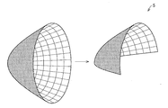
- FIG. 2 is a conceptual diagram showing the paraboloid of the parabolic mirror 5
- FIG. 3 (a) is a top view of the parabolic mirror 5
- FIG. 3 (b) is a front view
- FIG. 3 (c) is a side view. is there.
- FIGS. 3A to 3C show an example in which the parabolic mirror 5 is formed by hollowing out the inside of a rectangular parallelepiped member so as to illustrate the explanatory drawings in an easy-to-understand manner.
- the parabolic mirror 5 is obtained by cutting a curved surface (parabolic curved surface) formed by rotating the parabola around the axis of symmetry of the parabola with a plane including the rotational axis.
- the partial curved surface is at least partially included in the reflecting surface.
- the curve indicated by reference numeral 5a indicates a parabolic surface.
- the opening 5b exit of illumination light
- the opening 5b is a semicircle.
- the laser element 2 is disposed outside the parabolic mirror 5, and the parabolic mirror 5 is formed with a window portion 6 that transmits or passes the laser light.
- the window 6 may be an opening or may include a transparent member that can transmit light in the wavelength range of laser light emitted from the laser element 2 that is an excitation light source.
- a transparent plate provided with a filter that transmits laser light and reflects white light (fluorescence of the light emitting unit 4) may be provided as the window unit 6. In this configuration, the fluorescence of the light emitting unit 4 can be prevented from leaking from the window unit 6, and the use efficiency of the fluorescence can be increased.
- One common window portion 6 may be provided for the plurality of laser elements 2, or a plurality of window sections 6 corresponding to the respective laser elements 2 may be provided.
- a part that is not a parabola may be included in a part of the parabola mirror 5.
- the reflecting mirror may include a parabolic mirror having a closed circular opening or a part thereof.
- the reflecting mirror is not limited to a parabolic mirror, and may be an elliptical mirror or a free-form surface mirror. In other words, the reflecting mirror only needs to include at least a part of a curved surface formed by rotating a figure (ellipse, circle, parabola) about the rotation axis on the reflecting surface.
- the metal base 7 is a plate-like support member that supports the light emitting unit 4 and is made of metal (for example, copper or iron). Therefore, the metal base 7 has high thermal conductivity and can efficiently dissipate heat generated in the light emitting unit 4.
- the member which supports the light emission part 4 is not limited to what consists of metals, The member containing substances (ceramics etc.) other than a metal with high heat conductivity may be sufficient. However, it is preferable that the surface of the metal base 7 in contact with the light emitting unit 4 functions as a reflecting surface.
- the surface is a reflection surface
- the fluorescence can be reflected by the reflection surface and directed to the parabolic mirror 5.
- the laser light incident from the upper surface of the light emitting unit 4 can be reflected by the reflecting surface and again directed to the inside of the light emitting unit 4 to be converted into fluorescence.
- the metal base 7 Since the metal base 7 is covered with the parabolic mirror 5, it can be said that the metal base 7 has a surface facing the reflection curved surface (parabolic curved surface) of the parabolic mirror 5. It is preferable that the surface of the metal base 7 on the side where the light emitting unit 4 is provided is substantially parallel to the rotation axis of the paraboloid of the parabolic mirror 5 and substantially includes the rotation axis.
- the fins 8 function as a cooling unit that cools the metal base 7.
- the fin 8 has a plurality of heat radiating plates, and increases the heat radiation efficiency by increasing the contact area with the atmosphere.
- the fins 8 are made of aluminum that is black anodized.
- the cooling unit that cools the metal base 7 may have a cooling (heat dissipation) function, and may be a heat pipe, a water cooling method, or an air cooling method.
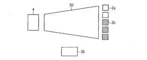
- FIG. 4 is a schematic diagram for explaining an example of the present embodiment. Note that the description of the contents described with reference to FIG.
- the headlamp 1 includes at least two laser elements 2 a, three laser elements 2 b, a light emitting unit 4, and a tapered light guide unit 20.
- the tapered light guide 20 guides the laser light oscillated by the laser element 2 to the light emitting part 4.
- the tapered light guide 20 has an incident end where the laser beam emitted from the laser element 2 is incident and an emission end where the laser beam incident from the incident end is emitted.
- the tapered light guide 20 has a surrounding structure surrounded by a light reflecting side surface that reflects the laser light incident on the incident end, and the sectional area of the exit end of the tapered light guide 20 is as follows. The cross-sectional area of the incident end is smaller.
- the tapered light guide 20 has a rectangular pyramid-shaped cylindrical shape as a whole, and the cross section (opening) of the emission end is, for example, a rectangle of 1 mm ⁇ 3 mm.
- the cross section (opening) is, for example, a rectangle of 15 mm ⁇ 15 mm.
- the shape of the tapered light guide 20 is not limited to a quadrangular frustum shape, and various shapes such as a polygonal frustum shape, a truncated cone shape, and an elliptic frustum shape other than the quadrangular frustum shape can be adopted. Further, the length from the incident end to the exit end can be set arbitrarily.
- the tapered light guide unit 20 condenses the laser beam incident on the incident end part to the emission end part having a smaller cross-sectional area than the incident end part, and then emits the laser light to the light emitting unit 4. it can. For this reason, even if it aims at high output using the some laser element 2, the light emission part 4 can be designed small. That is, it is possible to realize a headlamp 1 with high output and high brightness.
- the tapered light guide 20 is made of BK (borosilicate crown) 7, quartz glass, acrylic resin, or other transparent material.
- the laser beams emitted from the two laser elements 2a and the three laser elements 2b are condensed on the emission end of the tapered light guide 20, and the condensed laser lights are collected.
- the light emitting unit 4 is irradiated.
- the headlamp 1 includes a light-emitting unit that is irradiated with laser light from the opening side of the parabolic mirror 5 (this is referred to as a “reflection-type light-emitting unit” in the present application).
- the provided headlamp is referred to as a reflective headlamp.
- the light emitting unit 4 is irradiated with laser light from the side where the parabolic mirror 5 is disposed, whereby the light emitting unit 4 emits fluorescence on the laser light irradiation surface. Then, the fluorescence is reflected by the parabolic mirror 5 and irradiated outside the headlamp.
- the transmission filter is formed of a material that transmits (pseudo) white light (incoherent light) generated by converting the laser light in the light emitting unit 4. For example, a transparent resin plate or an inorganic glass plate is used. Used.
- FIG. 5 is a diagram for explaining another embodiment in which the configuration of FIG. 4 is used for a transmission type headlamp.
- the description similar to the matter demonstrated with reference to FIG. 1 etc. is abbreviate
- the transmissive headlamp is a headlamp that irradiates the light emitting unit 4 with laser light from the side opposite to the opening of the parabolic mirror 5.
- the laser light emitted from the emission end of the tapered light guide 20 passes through the transparent high thermal conductive plate 40 and the light emitting part 4.
- the laser light excites the phosphor contained in the light emitting unit 4 in the process of being transmitted and scattered inside the light emitting unit 4 to generate fluorescence, that is, the light emitting unit generates fluorescence. Fluorescence generated from the light emitting unit 4 is reflected by the parabolic mirror 5 and irradiated outside the headlamp.
- such a type of headlamp is referred to as a transmissive headlamp.
- the transmissive headlamp shown in FIG. 5 includes at least two laser elements 2a, three laser elements 2b, a light emitting unit 4, a tapered light guide unit 20, a parabolic mirror 5, and a setting unit 30. (Details will be described later) and a transparent high thermal conductive plate 40.
- the transparent high thermal conductive plate 40 transmits light having the wavelength of the laser light emitted from the laser element 2a and the laser element 2b.
- the transparent high heat conductive plate 40 abuts on the light emitting unit 4 and the parabolic mirror 5 on the laser light irradiation surface side of the light emitting unit 4.
- the transparent high heat conductive plate 40 conducts the heat generated in the light emitting unit 4 to the parabolic mirror 5.
- the transparent high heat conductive plate 40 can efficiently radiate the heat generated in the light emitting unit 4, can suppress deterioration of the light emitting unit 4 due to heat, and further suppress the temperature rise of the light emitting unit 4. Therefore, it can suppress that the luminous efficiency of the light emission part 4 becomes low with a temperature rise.
- the material of the transparent high heat conductive plate 40 is not particularly limited as long as it has the above function.
- FIG. 4 can be suitably applied to both the reflection type and the transmission type headlamps.
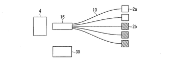
- FIG. 6 is a schematic diagram for explaining another example of the present embodiment.
- the description similar to the matter demonstrated with reference to FIG. 1 etc. is abbreviate
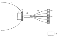
- the headlamp 1 includes at least two laser elements 2 a, three laser elements 2 b, a light emitting unit 4, an optical fiber 10, and a ferrule 15.
- the optical fiber 10 is a flexible light guide member that guides the laser light oscillated by the laser element 2 to the light emitting unit 4.
- the optical fiber 10 has an incident end that receives laser light and an output end that emits laser light incident from the incident end.
- the optical fiber 10 has a two-layer structure in which an inner core is covered with a clad having a refractive index lower than that of the core.
- the core is mainly composed of quartz glass (silicon oxide) having almost no absorption loss of laser light
- the clad is composed mainly of quartz glass or a synthetic resin material having a refractive index lower than that of the core.
- the optical fiber 10 is made of quartz having a core diameter of 200 ⁇ m, a cladding diameter of 240 ⁇ m, and a numerical aperture NA of 0.22.
- the structure, thickness, and material of the optical fiber 10 are as described above.
- the cross section perpendicular to the major axis direction of the optical fiber 10 may be rectangular.
- the member which has the flexibility which combined members other than an optical fiber, or an optical fiber and another member may be used as a light guide member.
- the light guide member only needs to have an incident end that receives the laser light oscillated by the laser element 2 and an output end that emits the laser light incident from the incident end.
- an incident part having an incident end part and an emitting part having an exit end part may be formed as members different from the optical fiber, and the incident part and the outgoing part may be connected to both end parts of the optical fiber.
- the ferrule 15 holds a plurality of emission end portions of the optical fiber 10 in a predetermined pattern with respect to the laser light irradiation surface of the light emitting unit 4.
- the ferrule 15 may have holes for inserting the emission end portion of the optical fiber 10 formed in a predetermined pattern, and can be separated into an upper part and a lower part.
- the exit end portion may be sandwiched between the formed grooves.
- the ferrule 15 may be fixed to the parabolic mirror 5 by a rod-like or cylindrical member extending from the parabolic mirror 5.
- the material of the ferrule 15 is not particularly limited, and may be stainless steel, for example.
- the laser light emitted from the two laser elements 2a and the three laser elements 2b is irradiated to the light emitting unit 4 through the optical fiber 10 connected to each laser element 2.
- FIG. 7 is a diagram for explaining another embodiment in which the configuration of FIG. 6 is used in a transmission headlamp.
- FIG. 7 includes at least two laser elements 2a, three laser elements 2b, a light emitting unit 4, an optical fiber 10, a ferrule 15, a parabolic mirror 5, and a setting unit. 30 (details will be described later) and a transparent high thermal conductive plate 40.
- a transparent high thermal conductive plate 40 since each of these structural members has already been described with reference to FIG. 5, FIG. 6, etc., description here is not repeated. However, it will be described again that the configuration of FIG. 6 can be suitably applied to both the reflective and transmissive head lamps.
- the light emitting unit 4 used in the first and second embodiments includes a phosphor and a sealing agent for sealing the phosphor.
- a phosphor As the phosphor, CASN: Eu 2+ and Ca ⁇ -SiAlON: Ce 3+ are used.
- Inorganic glass is used as the sealing material, and the basic composition of the inorganic glass is SiO 2 —B 2 O 3 —CaO—BaO—Li 2 O—Na 2 O.
- the light emitting unit 4 is in a state where the phosphor is dispersed in the inorganic glass.
- the laser element 2a has an oscillation wavelength of 405 nm
- the laser element 2b has an oscillation wavelength of 460 nm.
- a glass material made of BK-7 is used as a condensing member.
- the laser element 2a and the laser element 2b each emit laser light having a different wavelength and change its output, thereby providing illumination with different chromaticities. Light is radiated to the outside. Therefore, the chromaticity of the headlamp 1 can be changed according to changes in weather, road surface conditions, etc., and illumination light with excellent visibility can be obtained.
- each of the laser element 2a and the laser element 2b emits laser beams having different wavelengths and can change the output thereof, so that not only the chromaticity but also the luminous flux is changed. be able to.
- the illumination light having a lower color temperature can irradiate the front of the vehicle more widely, so that it is possible to provide a headlamp suitable for irradiation in bad weather (rainy weather, fog occurrence, etc.).
- FIG. 8 is a conceptual diagram showing the direction in which the headlamp 1 is disposed when the headlamp 1 is applied to a headlamp of an automobile (vehicle) 50.
- the headlamp 1 may be disposed on the head of the automobile 50 so that the parabolic mirror 5 is positioned vertically downward.
- the front surface of the automobile 50 is brightly illuminated and the front lower side of the automobile 50 is appropriately illuminated by the above-described light projection characteristics of the parabolic mirror 5.
- the headlamp 1 may be applied to a traveling headlight (high beam) for automobiles, or may be applied to a passing headlamp (low beam). Further, during the traveling of the automobile 50, the light intensity distribution of the laser light irradiated on the irradiation surface of the light emitting unit 4 may be controlled according to the traveling state. Accordingly, it is possible to project light with an arbitrary projection pattern while the automobile 50 is running, and it is possible to improve user convenience.
- the headlamp 1 may be applied not only to a vehicle headlamp but also to other lighting devices.
- An example of application of the headlamp 1 is a downlight (details will be described later).
- a downlight is a lighting device installed on the ceiling of a structure such as a house or a vehicle.
- the lighting device of the present invention may be realized as a headlamp of a moving object other than a vehicle (for example, a human, a ship, an aircraft, a submersible, a rocket, etc.), or other than a searchlight, a projector, or a downlight. It may be realized as an indoor lighting fixture (stand lamp, etc.) or an outdoor lighting fixture.
- the headlamp 1 can solve the subject of the conventional headlamp. That is, in the conventional headlamp, in the configuration in which the outputs of at least two light sources having different chromaticities are changed, there are as many light emitting points as the number of light sources. Therefore, the conventional headlamp requires a complicated optical design when incorporating a plurality of light emitting points into an optical system such as a reflecting mirror or a lens. Further, in the conventional headlamp, in order to realize a highly efficient optical system, the optical system needs to have a large size.
- the headlamp 1 can change the outputs of the laser elements 2a and 2b having different wavelengths. Since the absorptivity and the light emission efficiency of the light emitting unit 4 are different depending on the wavelength, when the output of each of the laser element 2a and the laser element 2b having different wavelengths is changed, the wavelength component changes as synthetic excitation light having different wavelengths. As a result, the emission spectrum (emission intensity) of the light emitting unit 4 and the spectrum shape of the excitation light transmitted (or reflected) by the light emitting unit 4 also change. Thereby, the spectrum of illumination light finally obtained, that is, chromaticity also changes.
- the optical system combined with this may be one unit. Therefore, the headlamp can be reduced in size and weight, and the optical design of the headlamp is facilitated. .
- the headlamp 1 may include a setting unit 30 that presets the combination of the outputs of the laser element 2a and the laser element 2b so that the light emitted from the light emitting unit 4 has a desired chromaticity.
- the headlamp 1 may include a setting unit 30 that sets the outputs of the laser element 2a and the laser element 2b so that the light emitted from the light emitting unit 4 is included in a desired range in the chromaticity diagram. .
- the setting unit 30 may be realized in any manner.
- an input device such as a keyboard capable of adjusting the outputs of the laser element 2 a and the laser element 2 b is provided inside or outside the headlamp 1.
- a storage device is provided inside or outside the headlamp 1.
- a storage device stores a table in which the outputs (output values) of the laser elements 2a and 2b and the chromaticity of the illumination light irradiated to the outside of the headlamp 1 corresponding to the outputs (output values) are associated with each other. To store.
- a control unit provided inside or outside the headlamp 1 automatically adjusts the outputs of the laser element 2a and the laser element 2b with reference to the input and the table stored in the storage device. As a result, the headlamp 1 irradiates the device with the light having a certain chromaticity.
- the headlamp 1 irradiates the light of the certain chromaticity to the outside of the apparatus.
- the push button may be realized as a touch panel provided on the headlamp 1.
- the setting unit 30 can be realized in various modes. Since the headlamp 1 includes the setting unit 30, it is possible to reduce time and labor for repeatedly adjusting the output of excitation light having different wavelengths, and thus it is possible to improve user convenience.
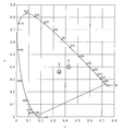
- FIG. 9 is a chromaticity diagram for explaining the effect obtained by the headlamp 1.
- the point P in the figure indicates the chromaticity point of the fluorescence emitted by the light emitting unit 4 by the laser light emitted from the laser element 2a and the laser element 2b.
- Point Q indicates a chromaticity point after the outputs of the laser element 2a and the laser element 2b are changed.
- each of the laser element 2a and the laser element 2b emits laser beams having different wavelengths, and the output can be changed.
- the chromaticity point of the fluorescence emitted from the light emitting unit 4 can be changed from the point P to the point Q by changing the outputs of the laser elements 2a and 2b.
- the change position of the chromaticity point is not limited to the point P and the point Q, and FIG. 9 shows an example only.
- the light emitting point is only one light emitting part, and it is not necessary to change the position of the light emitting point.
- the optical system combined with this may be one unit. Therefore, the headlamp 1 can be reduced in size and weight, and the optical design of the headlamp 1 is also improved. It becomes easy.
- the headlamp 1 can easily change the characteristics of illumination light such as spectrum, chromaticity, and color temperature with a simple structure.
- the configuration may include a setting unit that sets the outputs of the plurality of excitation light sources so that the light emitted from the light-emitting unit is included in a desired range in the chromaticity diagram.
- FIG. 10 is a cross-sectional view showing a schematic configuration of the headlamp 1 according to the present embodiment
- FIG. 11 is a view showing a positional relationship between the light emitting unit 4 and the emission end 10r of the optical fiber 10. As shown in FIG.
- the emitting end 10r may be in contact with the laser light irradiation surface (light receiving surface) 4a, or may be arranged at a slight interval.
- the laser beam emitted from the emission end portion 10r is appropriately applied to the laser beam irradiation surface 4a due to the impact on the headlamp. May not be irradiated.
- the laser light is emitted from the parabolic mirror 5 without being converted into incoherent light by the light emitting unit 4.
- the light emitting unit 4 when the light emitting unit 4 is provided in the transmission filter 60 as described above, a space surrounded by the parabolic mirror 5 and the transmission filter 60 (the parabolic mirror 5 and the opening of the parabolic mirror 5 is formed).
- the laser beam propagates through the space) and is emitted from the parabolic mirror 5.
- the emission end 10r and the laser light irradiation surface 4a are in contact (close to each other) or the optical path of the laser light is covered. That is, an optical path of the laser beam between the emission end 10r and the laser beam irradiation surface 4a and a space outside the optical path (for example, the parabolic mirror 5 and the transmission filter 60). It is preferable to spatially block the enclosed space).
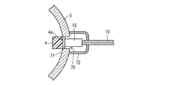
- a hollow portion 70 into which the emission end portion 10 r is inserted is formed at the bottom of the parabolic mirror 5, and the center of the laser light irradiation surface 4 a of the light emitting portion 4 is located at the center of the hollow portion 70. As shown, a light emitting unit 4 is provided. Further, a ferrule 15 that holds the emission end portion 10 r is inserted into the hollow portion 70. That is, in FIG. 10, in the hollow part 70 of the parabolic mirror 5, the laser light irradiation surface 4a and the emission end part 10r are close to each other.
- the laser light irradiation surface 4a and the emission end 10r are close to each other, the laser light emitted from the emission end 10r can be reliably irradiated onto the laser light irradiation surface 4a. For this reason, for example, when the headlamp 100 receives some impact, the laser light irradiation surface 4a is not irradiated with laser light having an output level that is harmful to the human body (that is, the laser light is not converted into incoherent light). B) It can be prevented from leaking directly to the outside. Therefore, the headlamp 100 with high safety can be realized.
- the laser beam irradiation surface 4a and the emission end 10r may not be close to each other. . That is, the light emitting unit 4 only needs to be provided so that the laser light irradiation surface 4 a is outside the space formed by the parabolic mirror 5 and the opening of the parabolic mirror 5.
- the “outside of the space” is a concept including the boundary surface of the space and the outside of the space.
- the laser light irradiation surface 4 a is at least the same surface as the reflection surface of the parabolic mirror 5 that reflects the light emitted from the light emitting unit 4 (the side facing the outside of the parabolic mirror 5, that is, the above-described surface).
- the light emitting unit 4 is provided so as to be outside the space.
- the light emitting unit 4 itself may be provided outside the parabolic mirror 5 and inside the headlamp 100.
- the light emitting unit 4 is provided inside a cylinder (the material of the cylinder is a material that blocks laser light) obtained by extending the hollow portion 70.
- a part of the light emitting part 4 may exist in the space, and the laser light irradiation surface 4a may exist outside the space (inside the hollow part 70).
- the shape and size of the laser light irradiation surface 4 a are the same as the shape and size of the opening surface of the hollow portion 70.
- the light emitting unit 4 does not receive high-power laser light inside the space. That is, it is possible to prevent laser light having an output level harmful to the human body from propagating through the space and leaking in the light irradiation direction of the headlamp 100. Further, for example, when the headlamp 100 receives some impact, even if a situation occurs in which the laser beam is not irradiated onto the laser beam irradiation surface 4a, the laser beam leaks directly in at least the irradiation direction of the light. Can be prevented.
- the hollow portion 70 is formed at the bottom of the parabolic mirror 5, but is not limited thereto, and may be formed at any position of the parabolic mirror 5.
- the light emitting unit 4 is disposed so as to completely cover the hollow portion 70. Thereby, it is possible to prevent the laser light emitted from the emission end portion 10r from being emitted to the region surrounded by the parabolic mirror 5 and the transmission filter 60 and emitted from the opening of the parabolic mirror 5. For this reason, the hollow part 70 is formed so as to be equal to or smaller than the size of the laser light irradiation surface 4a (when the laser light irradiation surface 4a is a rectangle of 3 mm ⁇ 1 mm, the opening surface of the hollow part 70 is 3 mm 2 or less). Yes. In addition, if the light emission part 4 can completely cover the hollow part 70, the shape of the hollow part 70 may not necessarily be the same shape as the laser beam irradiation surface 4a.
- the light emitting unit 4 is held by the parabolic mirror 5 instead of the transmission filter 60, and (2 It is preferable that the laser beam irradiation surface 4a and the emission end 10r are brought close to each other, and (3) the light emitting unit 4 is disposed so as to completely cover the hollow portion 70.
- an extension 11 and a lens 12 are described.
- the extension 11 is provided in the front side part of the parabolic mirror 5, conceals the internal structure of the headlamp 100, improves the appearance, and enhances the sense of unity between the parabolic mirror 5 and the vehicle body.
- the extension 11 is also a member having a metal thin film formed on the surface thereof, like the parabolic mirror 5.
- the lens 12 is provided in the opening of the housing 13 and seals the headlamp. The light emitted from the light emitting unit 4 is emitted to the front of the headlamp 100 through the lens 12.
- the light emitting unit 4 and the ferrule 15 are provided via a heat radiating member 71. That is, the laser beam irradiation surface 4 a and the emission end portion 10 r are close to each other through the heat radiating member 71.
- the heat radiating member 71 dissipates heat generated in the light emitting part 4 when the light emitting part 4 is irradiated with laser light, and is provided in contact with the laser light irradiation surface 4a.
- the material of the heat radiating member 71 is a transparent material having a high thermal conductivity, such as gallium nitride, magnesia (MgO), or sapphire.
- the heat dissipation member 71 is a plate-like member, and is provided inside the hollow portion 70 so as to cover the opening surface of the hollow portion 70.
- the laser beam irradiation surface 4a is bonded to one surface (laser beam emitting surface) of the heat radiation member 71 so as to be thermally coupled, and the other end (laser beam receiving surface) is in contact with the emitting end portion 10r.
- the light emitting unit 4 and the emission end 10r are arranged so as to be close to each other.
- the shape of the heat dissipation member 71 is not limited to a shape that covers the opening surface of the hollow portion 70 as long as the heat generated in the light emitting unit 4 can be dissipated to the parabolic mirror 5, for example. That is, it may be a linear member including a rod shape or a cylindrical shape extending from the parabolic mirror 5 and in contact with a part of the laser light irradiation surface 4a.
- the heat dissipating member 71 is a linear member and is provided only at a position away from the center of the optical axis (the end of the laser light irradiation surface 4a), it is not necessarily transparent. However, from the viewpoint of the utilization efficiency of the laser beam, it is preferable that it is transparent. Further, if the heat radiating member 71 has a cylindrical shape and is provided only at the end of the laser light irradiation surface 4a, a heat radiating effect can be obtained by flowing or circulating a liquid or gas in the tube. It is also possible to increase.
- the heat radiation member 71 is provided in the hollow portion 70, and the emission end portion 10 r and the light emitting portion 4 are in close proximity via the heat radiation member 71. Therefore, the heat generated in the light emitting unit 4 due to the laser light irradiated on the laser light irradiation surface 4a can be dissipated to the parabolic mirror 5 via the heat radiating member 71, so that the long life of the light emitting unit 4 is achieved. Can be achieved. If this point is not taken into consideration, the heat radiating member 71 is not necessarily provided.
- the headlamp 100 does not irradiate the laser light irradiation surface 4a in the vicinity of the laser light irradiation surface 4a and the emission end portion 10r out of the laser light emitted from the emission end portion 10r.
- the light shielding unit 72 shields at least one of the laser light reflected by the laser light and the laser light reflected by the surface of the laser light irradiation surface 4a.
- the material of the light shielding part 72 may be any material as long as it blocks the wavelength of the laser light and the wavelength in the vicinity thereof.
- the laser light does not leak into the space surrounded by the parabolic mirror 5 and the transmission filter 60, and the laser light is placed in front of the headlamp 100. Can be prevented from being emitted.
- the laser light is transmitted to the hollow portion 70 (the light emitting portion 4 and the ferrule). 15).
- the light shielding part 72 By providing the light shielding part 72, even when the laser light irradiation surface 4a and the emission end 10r are brought close to each other, there is a situation in which the laser light irradiation surface 4a is not appropriately irradiated due to, for example, an impact on the headlamp 1. Even if it occurs, the laser beam can be reliably prevented from leaking outside from the hollow portion 70. Further, even when the laser light irradiation surface 4a and the emitting end portion 10r are separated from each other, the laser light is emitted from the space sealed by the light shielding portion 72, that is, leaks out from the hollow portion 70 to the outside. Can be prevented. Note that the light shielding portion 72 is not necessarily provided as long as the purpose is to prevent laser light from being emitted at least in front of the headlamp 100.
- the light shielding portion 72 is provided to prevent the laser light from leaking out of the hollow portion 70, particularly in a direction toward the outside of the parabolic mirror 5 (a direction other than the light irradiation direction).
- the present invention is not limited to this configuration, and the light shielding unit 72 may be provided to prevent the laser light from being emitted in the light irradiation direction.
- the light shielding unit 72 is at least between the laser beam irradiation surface 4a and the emission end 10r. You may provide so that the vicinity of the optical path of the laser beam formed may be covered. In that case, the light shielding part 72 forms a sealed space that covers at least the laser light irradiation surface 4a and the ferrule 15, and the shape thereof is, for example, a cylindrical shape.
- the material of the light shielding part 72 is preferably a material that blocks the wavelength of the laser light and the wavelength in the vicinity thereof and transmits the light emitted from the light emitting part 4.
- the laser light propagates through the space surrounded by the parabolic mirror 5 and the transmission filter 60 and is emitted from the opening of the parabolic mirror 5. Can be prevented.
- the laser light irradiation surface 4a and the opening surface of the hollow portion 70 have substantially the same size, but the opening surface may be smaller than the laser light irradiation surface 4a.
- the end of the laser beam irradiation surface 4 a may be directly connected to the parabolic mirror 5 and held by the parabolic mirror 5.
- the laser downlight 200 is an illumination device installed on the ceiling of a structure such as a house or a vehicle, and uses fluorescence generated by irradiating the light emitting unit 4 with laser light emitted from the laser element 2 as illumination light.
- a color mixture of fluorescence generated by irradiating the light emitting unit 4 with laser light emitted from the laser element 2 and light having a wavelength of excitation light that has been scattered and transmitted through the light emitting unit 4 is illuminated. It is used as light.
- an illumination device having the same configuration as the laser downlight 200 may be installed on the side wall or floor of the structure, and the installation location of the illumination device is not particularly limited.
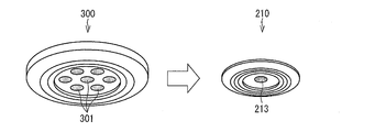
- FIG. 12 is a schematic view showing the external appearance of the light emitting unit 210 and the conventional LED downlight 300.
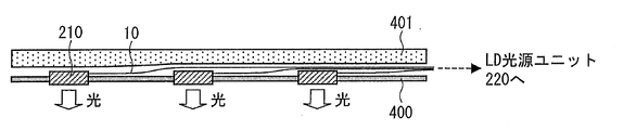
- FIG. 13 is a cross-sectional view of the ceiling where the laser downlight 200 is installed.
- FIG. 14 is a cross-sectional view of the laser downlight 200.
- a laser downlight 200 is embedded in a top plate 400 and emits illumination light, and an LD light source that supplies laser light to the light emitting unit 210 via the optical fiber 10.
- Unit 220 The LD light source unit 220 is not installed on the ceiling, but is installed at a position where the user can easily touch it (for example, a side wall of a house).
- the position of the LD light source unit 220 can be freely determined in this way because the LD light source unit 220 and the light emitting unit 210 are connected by the optical fiber 10.
- the optical fiber 10 is disposed in the gap between the top plate 400 and the heat insulating material 401.
- the light emitting unit 210 includes a housing 211, the optical fiber 10, the light emitting unit 4, and a light transmitting plate 213.
- a recess 212 is formed in the housing 211, and the light emitting unit 4 is disposed on the bottom surface of the recess 212.
- a metal thin film is formed on the surface of the recess 212, and the recess 212 functions as a reflecting mirror.
- a passage 214 for passing the optical fiber 10 is formed in the housing 211, and the optical fiber 10 extends to the light emitting unit 4 through the passage 214.
- the positional relationship between the emission end of the optical fiber 10 and the light emitting unit 4 is the same as described above.
- the translucent plate 213 is a transparent or translucent plate disposed so as to close the opening of the recess 212.
- the fluorescence of the light emitting unit 4 is emitted as illumination light through the light transmitting plate 213.
- the translucent plate 213 may be removable from the housing 211 or may be omitted.
- the light emitting unit 210 has a circular outer edge, but the shape of the light emitting unit 210 (more precisely, the shape of the housing 211) is not particularly limited.
- the LD light source unit 220 includes a laser element 2, a lens 3, and an optical fiber 10.
- the incident end which is one end of the optical fiber 10 is connected to the LD light source unit 220, and the laser light oscillated from the laser element 2 enters the incident end of the optical fiber 10 via the lens 3. Is done.
- a pair of the laser element 2 and the lens 3 is shown inside the LD light source unit 220 shown in FIG. 14, but when there are a plurality of light emitting units 210, a bundle of optical fibers 10 extending from the light emitting units 210, respectively. May be guided to one LD light source unit 220.
- a pair of a plurality of laser elements 2 and lenses 3 (or a pair of a plurality of laser elements 2 and one rod-shaped lens) is accommodated in one LD light source unit 220.
- 220 functions as a centralized power supply box.
- FIG. 15 is a cross-sectional view showing a modified example of the installation method of the laser downlight 200.
- a modified example of the installation method of the laser downlight 200 only a small hole 402 through which the optical fiber 10 is passed is formed in the top plate 400. It can also be said that the unit 210) is attached to the top plate 400 using a strong adhesive tape or the like. In this case, there are advantages that restrictions on installation of the laser downlight 200 are reduced, and that construction costs can be significantly reduced.
- the conventional LED downlight 300 includes a plurality of light transmitting plates 301, and illumination light is emitted from each light transmitting plate 301. That is, the LED downlight 300 has a plurality of light emitting points.
- the LED downlight 300 has a plurality of light emitting points because the light flux of light emitted from each light emitting point is relatively small. Therefore, if a plurality of light emitting points are not provided, light having a sufficient light flux as illumination light is provided. This is because it cannot be obtained.
- the laser downlight 200 is an illumination device with a high luminous flux, it may have one light emitting point. Therefore, it is possible to obtain an effect that the shadow caused by the illumination light is clearly displayed. Moreover, the color rendering property of illumination light can be improved by making the phosphor of the light emitting unit 4 a high color rendering phosphor (for example, a combination of several kinds of oxynitride phosphors).
- FIG. 16 is a cross-sectional view of the ceiling where the LED downlight 300 is installed.
- a casing 302 that houses an LED chip, a power source, and a cooling unit is embedded in the top plate 400.
- the housing 302 is relatively large, and a recess along the shape of the housing 302 is formed in a portion of the heat insulating material 401 where the housing 302 is disposed.
- a power line 303 extends from the housing 302, and the power line 303 is connected to an outlet (not shown).
- Such a configuration causes the following problems. First, since there is a light source (LED chip) and a power source that are heat sources between the top plate 400 and the heat insulating material 401, the use of the LED downlight 300 raises the ceiling temperature, and the cooling efficiency of the room. Problem arises.
- LED chip light source
- power source that are heat sources between the top plate 400 and the heat insulating material 401
- the LED downlight 300 requires a power source and a cooling unit for each light source, resulting in a problem that the total cost increases.
- the housing 302 is relatively large, there is a problem that it is often difficult to arrange the LED downlight 300 in the gap between the top 400 and the heat insulating material 401.
- the LED downlight is integrated with a metal block such as a heat radiating fin for heat dissipation of the LED chip, its weight increases when viewed as an LED downlight. Therefore, there arises a problem that a special mounting frame is required to hold the ceiling.
- the light emitting unit 210 does not include a large heat source, the cooling efficiency of the room is not reduced. As a result, an increase in room cooling costs can be avoided.
- the laser downlight 200 can be made small, thin, and lightweight. As a result, the space restriction for installing the laser downlight 200 is reduced, and installation in an existing house is facilitated.
- the light emitting unit 210 can be installed on the surface of the top plate 400 as described above. It is possible to reduce the installation restrictions as compared with the downlight 300 and to significantly reduce the construction cost.
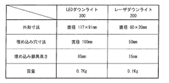
- FIG. 17 is a diagram for comparing the specifications of the laser downlight 200 and the LED downlight 300. As shown in the figure, in the laser downlight 200, in one example, the volume is reduced by 94% and the mass is reduced by 86% compared to the LED downlight 300.
- the LD light source unit 220 can be installed at a place (height) that can be easily reached by the user, the laser element 2 can be easily replaced even if the laser element 2 breaks down. Further, by guiding the optical fibers 10 extending from the plurality of light emitting units 210 to one LD light source unit 220, the plurality of laser elements 2 can be managed collectively. Therefore, even when a plurality of laser elements 2 are replaced, the replacement can be easily performed.
- a light beam of about 500 lm can be emitted with a power consumption of 10 W, but in order to realize the light of the same brightness with the laser downlight 200, 3 .3W light output is required. If the LD efficiency is 35%, this light output corresponds to power consumption of 10 W, and the power consumption of the LED downlight 300 is also 10 W. Therefore, there is no significant difference in power consumption between the two. Therefore, in the laser downlight 200, the above-described various advantages can be obtained with the same power consumption as that of the LED downlight 300.
- the laser downlight 200 includes the light source unit 220 including at least one laser element 2 that emits laser light, the light emitting unit 4 and at least one light emitting unit 210 including the concave portion 212 as a reflecting mirror, and light emission. And an optical fiber 10 that guides the laser light to each of the units 210.
- a plurality of emission end portions of the optical fiber 10 are arranged with respect to one light emitting unit 4 included in the light emitting unit 210, and in the light intensity distributions respectively possessed by laser beams emitted from the plurality of emission end portions.
- the portion with the highest light intensity is irradiated to different portions of the light emitting units 4 to be arranged.
- the laser downlight 200 it is possible to reduce the possibility that the light emitting section 4 is significantly deteriorated by irradiating the laser light intensively on one place of the light emitting section 4. As a result, a long-life laser downlight 200 can be realized.
- the laser downlight 200 can also achieve the following effects.
- the laser downlight 200 can change the chromaticity of the illumination light only by changing the output of the laser light while having one light emitting point. For this reason, the laser downlight 200 does not physically replace the light emitting unit manually, and uses a mechanical driving means, a filter, or the like for physically replacing the light emitting unit 4.
- Large-scale mechanism such as a mechanism for changing the chromaticity of the illumination light emitted from the light source, a mechanism for changing the chromaticity of the illumination light by turning on and off the light sources that have multiple light sources that emit light of different colors The chromaticity of the illumination light emitted from one light emitting point can be changed without providing near the light emitting portion.
- the laser downlight 200 has an effect that the shadow due to the illumination light is beautiful because it has a single light emitting point, while it is effective in situations (during meals, watching TV, family gatherings, etc.) It is possible to change the chromaticity according to the mood (morning, noon, night, etc.) and mood (if you want to relax).
- an illumination device includes a plurality of excitation light sources that emit excitation light and a light emitting unit that emits light by receiving excitation light emitted from the plurality of excitation light sources.
- the plurality of excitation light sources may emit excitation light having different wavelengths and change the output thereof.
- the light-emitting part of a lighting device has different absorptance and luminous efficiency depending on the wavelength of the excitation light to be irradiated. Therefore, when the output of each excitation light source having a different wavelength is changed as in the above lighting device,
- the spectrum of light is not a spectrum having a single peak wavelength as in a conventional LED, but a spectrum in which light of different wavelengths is added, that is, a spectrum shape having a plurality of steep peaks.
- the wavelength component of the light emitted from the light emitting portion changes. That is, the emission spectrum (emission intensity) of the light emitting unit and the spectrum shape of the excitation light transmitted (or reflected) by the light emitting unit are changed. Thereby, the spectrum of the illumination light finally obtained, that is, chromaticity can be changed.
- the spectrum refers to the wavelength dependence of the emission intensity
- the change in the spectrum shape means that the emission intensity changes or the chromaticity changes.
- each of the plurality of excitation light sources emits excitation light having different wavelengths and changes its output, whereby the spectral shape of the illumination light is changed. That is, it is possible to emit illumination light having different chromaticities.
- the light emitting point is one light emitting part, and there is no need to change the position of the light emitting point.
- a single optical system can be combined with the light emitting point. Therefore, the lighting device can be reduced in size and weight, and the optical design of the lighting device can be easily performed. Become.
- the illumination light emitted to the outside of the illumination device includes light emitted from the light emitting unit and excitation light having different wavelengths, and excitation of the different wavelengths.
- the light output may be greater than zero.
- the illumination light irradiated to the outside of the illuminating device includes light emitted from the light emitting unit and excitation light having different wavelengths (transmitted and reflected by the light emitting unit). At this time, the output of the excitation light having the different wavelength is greater than 0, and the wavelengths of the excitation light sources are different.
- the illumination device can irradiate illumination light having different chromaticities by changing the output of excitation light greater than zero.
- the illuminating device which concerns on one Embodiment of this invention is the structure provided with the setting part which presets the combination of the output of several said excitation light source so that the light light-emitted by the said light emission part may have desired chromaticity. It may be.
- the illumination device includes a setting unit that presets combinations of outputs of the plurality of excitation light sources so that the light emitted from the light emitting unit has a desired chromaticity. Therefore, setting in the setting unit is performed in advance, so that light having a desired chromaticity can be obtained from the lighting device without requiring time and labor, and user convenience can be improved.
- the illumination device includes a setting unit that sets the outputs of the plurality of excitation light sources so that the light emitted from the light emitting unit is included in a desired range in the chromaticity diagram. It may be the composition provided.
- the illumination device includes a setting unit that sets the outputs of the plurality of excitation light sources so that the light emitted from the light-emitting unit is included in a desired range in the chromaticity diagram. Is provided. Therefore, the setting in the setting unit is performed in advance, so that the light emitted from the light emitting unit can be adjusted so as to be included in a desired range in the chromaticity diagram without requiring time and labor. Convenience can be improved.
- an illumination device includes a light guide unit that guides excitation light emitted from the plurality of excitation light sources, and the light guide unit transmits the guided excitation light to the light emitting unit.
- the light may be condensed.
- the plurality of excitation light sources and the light emitting unit can be arranged at a distance, and the heat generated in the excitation light source and the light emitting unit can be dispersed.
- the illumination device includes a light guide unit that guides excitation light emitted from the plurality of excitation light sources, and the light guide unit is excited from each of the plurality of excitation light sources.
- a plurality of optical fibers that receive light may be included, and the emission end portions of the excitation light included in the plurality of optical fibers may be configured to be bundled.
- the optical fiber has flexibility and can be easily adjusted in length. Therefore, with the above configuration, when the excitation light emitted from the excitation light source is guided to the light emitting unit, the position of the excitation light source can be freely changed, that is, the degree of freedom of the installation position (layout) of the excitation light source. Will improve.
- the emission end portions of the excitation light of the plurality of optical fibers are bundled, all the emission end portions of the plurality of optical fibers can be stably arranged in the vicinity of the light emitting portion. Further, the bundle of optical fibers enables the emission end portion to be focused at one place, contributing to the compactness of the lighting device. Furthermore, by bundling optical fibers, it is possible to stably irradiate the light emitting unit with excitation light, and to provide a user with a lighting device that can maintain a stable light distribution.
- the light emitting unit may include a phosphor that emits fluorescence upon receiving the excitation light.
- the excitation light emitted from the excitation light source is converted into fluorescence by the phosphor included in the light emitting unit, and the fluorescence and the excitation light having the different wavelengths transmitted and reflected by the light emitting unit are synthesized. It is emitted as illumination light outside the illumination device.
- the illumination device according to an embodiment of the present invention can easily emit the illumination light having different spectral shapes, that is, chromaticity, by changing the output of the excitation light having different wavelengths. it can.
- the illumination device can also suitably realize a configuration in which the light emitting unit includes a phosphor that emits fluorescence upon receiving the excitation light.
- the light emitting unit may include a scatterer that scatters the excitation light.
- the excitation light emitted from the excitation light source is scattered by the scatterer included in the light emitting unit, and the scattered light and the excitation light having the different wavelengths transmitted and reflected by the light emitting unit are combined and illuminated. It is emitted as illumination light to the outside of the apparatus.
- the illumination device can easily emit the illumination light having different spectral shapes, that is, chromaticity, by changing the output of the excitation light having different wavelengths. it can.
- the illumination device can be suitably realized in a configuration in which the light emitting unit includes a scatterer that scatters the excitation light.
- the light emitting unit has a light receiving surface that receives excitation light emitted from the excitation light source, and the light receiving surface emits light emitted from the light emitting unit.
- the reflection mirror may be provided so as to be outside the space formed by the reflecting mirror that forms a light bundle traveling within a predetermined solid angle and the opening of the reflecting mirror.
- the excitation light In particular, high-power excitation light (for example, laser light) is not received inside the space. For this reason, it is possible to prevent the excitation light having an output level harmful to the human body from propagating through the space and leaking to the outside (at least the irradiation direction of the light emitted from the light emitting unit).
- the excitation light when the lighting device receives some impact, even if a situation occurs in which the excitation light is not irradiated on the light receiving surface, the excitation light leaks directly in at least the light irradiation direction. Can be prevented.
- the light emitting unit has a light receiving surface that receives excitation light emitted from the light guide unit, and the light guide unit is received from the excitation light source.
- An excitation end that emits excitation light to the light emitting part, and excitation light that has not been irradiated to the light receiving surface among the excitation light emitted from the emission end near the light receiving surface and the light emitting end.
- the light-shielding part which shields at least one of light and the excitation light reflected on the said light-receiving surface may be provided.
- the illumination device since the illumination device according to the embodiment of the present invention includes the light-shielding unit, for example, when a situation occurs in which excitation light is not appropriately irradiated to the light receiving surface due to an impact on the illumination device. It is possible to reliably prevent the excitation light from leaking outside. In the case of this configuration, since the excitation light does not propagate through the space formed by the reflecting mirror and the opening of the reflecting mirror, it can be prevented from being emitted in the irradiation direction of the light, and other than that It is also possible to prevent leakage in the direction.
- the light emitting unit has a light receiving surface that receives excitation light emitted from the light guide unit, and the light guide unit is received from the excitation light source. It may have a configuration in which an exit end that emits excitation light to the light emitting unit is provided, and the light receiving surface and the exit end are close to each other.
- the light receiving surface of the light emitting unit and the emission end of the light guide unit are close to each other, and excitation light (particularly high output excitation light) is formed by the reflecting mirror and the opening of the reflecting mirror. It does not propagate through space. For this reason, for example, when the lighting device receives some impact, it is possible to prevent a situation in which excitation light having an output level that is harmful to the human body does not irradiate the light receiving surface and leaks directly to the outside. Therefore, a highly safe lighting device can be realized.
- the illumination apparatus includes a reflecting mirror that reflects light emitted from the light emitting unit to form a light bundle that travels within a predetermined solid angle
- the reflecting mirror includes: A hollow portion into which the emission end portion is inserted is provided, and the hollow portion is provided with a heat dissipation member that dissipates heat generated in the light emitting portion when the light emitting portion is irradiated with the excitation light.
- the light receiving surface and the emission end may be in close proximity via the heat radiating member.
- the amount of heat generated in the light emitting portion increases correspondingly (the temperature of the light emitting portion increases), and thus the light emitting portion may be rapidly deteriorated.
- the heat radiating member is provided in the hollow portion of the reflecting mirror, and the emitting end and the light receiving surface are close to each other through the heat radiating member. Therefore, the heat generated in the light emitting part due to the excitation light applied to the light receiving surface can be dissipated to the reflecting mirror via the heat radiating member, so that the life of the light emitting part can be extended.
- the plurality of laser light sources include GaN, InN, and mixed crystal compounds thereof, and each oscillation wavelength is 400 nm or more and 420 nm or less, and each oscillation is performed.
- the difference in wavelength may be 10 nm or less.
- the power conversion efficiency of the laser light source can be increased. Therefore, the lighting device can increase the light emission efficiency.
- the oscillation wavelength of the laser light source is in the range of 400 nm or more and 420 nm or less, there are many phosphors having high excitation efficiency with respect to light in this wavelength range, and in particular, phosphors that emit blue light have light in this wavelength range. Excitation efficiency is high. Therefore, the total luminous efficiency of the lighting device can be increased.
- the plurality of laser light sources each have an oscillation wavelength greater than 450 nm and less than or equal to 530 nm, and a difference between the oscillation wavelengths is less than or equal to 10 nm. It may be.
- the safety of the laser light contained in the illumination light emitted from the illumination device to the retina can be improved. Therefore, the emission limit value that can realize eye-safe becomes higher than when the phosphor is excited using 450 nm laser light, and accordingly, the light output of the laser light that excites the phosphor can be set high. It becomes possible. Thereby, the illuminating device can emit higher-power illumination light.
- the oscillation wavelengths of a plurality of laser light sources are slightly different. It takes a lot of cost to prepare a plurality of laser light sources having the same oscillation wavelength, and the yield is also low.
- the difference in the oscillation wavelength is in the range of 10 nm or less, so it is not necessary to strictly select the laser light source, the total cost can be suppressed, and the yield is improved. be able to.
- the difference in the oscillation wavelength is in the range of 10 nm or less, it is not necessary to strictly select the variation in the oscillation wavelength due to the manufacturing process while keeping the excitation efficiency for the phosphor high, and the defect loss can be kept low. it can.
- vehicle headlamp may be configured to include any of the above-described lighting devices.
- the lighting device according to an embodiment of the present invention can be suitably applied to a vehicle headlamp.
- the vehicle can emit illumination light having different chromaticities without changing the position of the light emitting point.
- a headlamp can be realized, and the above conventional problems can be easily solved.
- the downlight according to the embodiment of the present invention may include the lighting device described above.
- each of the plurality of excitation light sources emits excitation light having different wavelengths and changes its output, thereby It is possible to emit illumination lights having different spectral shapes, that is, chromaticities.
- the chromaticity of the illumination light can be changed only by changing the output of the excitation light.
- the downlight is emitted from the light emitting unit without manually exchanging the light emitting unit manually and using mechanical driving means or a filter for physically exchanging the light emitting unit.
- a large-scale mechanism such as a mechanism for changing the chromaticity of the illumination light and a mechanism for changing the chromaticity of the illumination light by turning on and off the light sources. It is possible to change the chromaticity without providing it in the vicinity.
- conventional downlights often employ a configuration in which a plurality of LEDs having different chromaticities are prepared and the output of each LED is changed to be adjusted to a desired chromaticity. Therefore, the conventional downlight has a plurality of light emitting points and requires a large optical system.
- Another method is to change the chromaticity by mechanically attaching a filter to the light source.
- mechanical driving means there is a problem that it is necessary to provide mechanical driving means.
- the downlight according to an embodiment of the present invention solves the problems of the conventional downlight and has a single light emitting point. It is possible to achieve an effect that the chromaticity can be freely changed by simply changing the value.
- an illumination device includes a plurality of excitation light sources that emit excitation light and a light emitting unit that emits light by receiving excitation light emitted from the plurality of excitation light sources.
- Each of the plurality of excitation light sources is configured to emit excitation light having different wavelengths and change its output.
- the present invention is applied to an illuminating device that can irradiate illumination light having different chromaticities without changing the position of a light emitting point, and can be suitably used particularly for a vehicle headlamp and a downlight. .
- Headlamp (lighting device) 2 Laser element (excitation light source) 3 Lens (excitation light) 4 Light emitting part 5 Parabolic mirror 7 Metal base 8 Fin 10 Optical fiber (light guiding part) 15 Ferrule 30 Setting part 40 Transparent high heat conduction plate 50 Car (vehicle) 60 Transmission Filter 70 Hollow Part 71 Heat Dissipation Member 72 Light-shielding Part 20 Tapered Light Guide Part 30 Setting Part 200 Laser Downlight 210 Light-Emitting Unit 211 Housing 212 Recess 213 Translucent Plate 214 Passage 220 Light Source Unit 300 LED Downlight 301 Translucent Plate 302 Housing 303 Power supply line 400 Top plate 401 Heat insulating material
Landscapes
- Engineering & Computer Science (AREA)
- General Engineering & Computer Science (AREA)
- Physics & Mathematics (AREA)
- Optics & Photonics (AREA)
- Spectroscopy & Molecular Physics (AREA)
- Condensed Matter Physics & Semiconductors (AREA)
- General Physics & Mathematics (AREA)
- Electromagnetism (AREA)
- Non-Portable Lighting Devices Or Systems Thereof (AREA)
- Arrangement Of Elements, Cooling, Sealing, Or The Like Of Lighting Devices (AREA)
- Semiconductor Lasers (AREA)
Abstract
ヘッドランプ(1)は、レーザ光を出射する複数のレーザ素子(2)と、光を受けて発光する発光部(4)と、を備え、複数のレーザ光源(2)は、複数のレーザ光源(2)それぞれが互いに異なる複数の波長でレーザ光を発生させ、かつ、それぞれが発光部(4)を発光させることの可能な波長のレーザ光を発生させ、1つの発光部(4)に対して、複数のレーザ光源(2)からのレーザ光が照射される。
Description
本発明は、発光点の位置を変化させることなく、色度の異なる照明光を照射することが可能な照明装置、車両用前照灯、及びダウンライトに関する。
近年、励起光源としてLED(Light Emitting Diode)やLD(Laser Diode)等の半導体発光素子を用い、これらの励起光源から生じた励起光を、蛍光体を含む発光部に照射して照明光を発生させる発光装置の研究が盛んになってきている。
このような発光装置に関する技術の例として特許文献1が開示されている。
特許文献1の発光装置は、波長450nm以下のレーザ光を発するGaN系半導体レーザを励起光源として用い、レーザ光で励起されて可視域の蛍光を発する蛍光体を上記レーザと組み合わせている。そして、当該発光装置は、青色光や紫外線などの波長450nm以下の短い波長の光により蛍光体を励起し、それにより高輝度の発光を実現している。
しかしながら、特許文献1の発光装置を含め、従来の技術には次のような課題がある。
現在、LEDの小型化・高出力化が進んでおり、また、要求される性能も高度化してきている。例えば、1つのLED電球によって低色温度から高色温度まで調光できる装置が生活の質を高めるために求められており、また製品化もされている。
この調光手段としては、色度の異なる少なくとも2つ以上の光源の出力を変化させる構成であり、その発光点は、光源の個数に対応した数だけ存在する。すなわち、発光点は、複数存在する。そのため、複数の発光点を反射鏡やレンズなどの光学系に組み込む時には、発光点の位置が変化する、もしくは複数の発光点が存在するといった理由により複雑な光学設計が必要であり、なおかつ高効率の光学系を実現しようとすると、その光学系は大きなサイズのものが必要になるという課題がある。
また、特許文献1から4の何れも、複数の半導体レーザの出射する波長がそれぞれ異なっている構成については開示も示唆もしていない。
本発明は、上記の問題を解決するためになされたものであり、その目的は、発光点の位置を変化させることなく、色度の異なる照明光を照射することが可能な照明装置、車両用前照灯、およびダウンライトを提供することにある。
本発明の一実施形態に係る照明装置は、上記課題を解決するために、レーザ光を出射する複数のレーザ光源と、光を受けて発光する発光部と、を備え、複数の上記レーザ光源は、複数の当該レーザ光源それぞれが互いに異なる複数の波長でレーザ光を発生させ、かつ、それぞれが上記発光部を発光させることの可能な波長のレーザ光を発生させ、1つの上記発光部に対して、複数の上記レーザ光源からのレーザ光が照射されることを特徴としている。
本発明に係る照明装置は、レーザ光を出射する複数のレーザ光源と、光を受けて発光する発光部と、を備え、複数の上記レーザ光源は、複数の当該レーザ光源それぞれが互いに異なる複数の波長でレーザ光を発生させ、かつ、それぞれが上記発光部を発光させることの可能な波長のレーザ光を発生させ、1つの上記発光部に対して、複数の上記レーザ光源からのレーザ光が照射される構成である。
それゆえ、発光点の位置を変化させることなく、色度の異なる照明光を照射することが可能であるという効果を奏する。
以下、図面を参照しつつ、本実施の形態に係るヘッドランプについて説明する。なお、以下では主にヘッドランプについて説明しているが、ヘッドランプは本願発明を適用する照明装置の一例であり、本願を任意の照明装置に適用可能であることは言うまでもない。以下の説明では、同一の部品および構成要素には同一の符号を付している。それらの名称および機能も同じである。したがって、それらについての詳細な説明は繰り返さない。
本発明の実施の一形態について図1等に基づいて説明すれば、以下のとおりである。
〔ヘッドランプ1の構成〕
図1は、本発明の一実施形態に係るヘッドランプ(照明装置)1の概略構成を示す断面図である。図1に示すように、ヘッドランプ1は、レーザ素子(励起光源)2、レンズ3、発光部4、パラボラミラー5、金属ベース7、およびフィン8を備えている。
図1は、本発明の一実施形態に係るヘッドランプ(照明装置)1の概略構成を示す断面図である。図1に示すように、ヘッドランプ1は、レーザ素子(励起光源)2、レンズ3、発光部4、パラボラミラー5、金属ベース7、およびフィン8を備えている。
(レーザ素子2)
レーザ素子2は、励起光を出射する励起光源として機能する発光素子である。このレーザ素子2は、複数設けられており、複数のレーザ素子2のそれぞれから励起光としてのレーザ光が発振される。このレーザ素子2は、1チップに1つの発光点を有するものであってもよく、1チップに複数の発光点を有するものであってもよい。
レーザ素子2は、励起光を出射する励起光源として機能する発光素子である。このレーザ素子2は、複数設けられており、複数のレーザ素子2のそれぞれから励起光としてのレーザ光が発振される。このレーザ素子2は、1チップに1つの発光点を有するものであってもよく、1チップに複数の発光点を有するものであってもよい。
より具体的に、レーザ素子2は、第一の発振波長を有するレーザ素子2aと、第二の発振波長を有するレーザ素子2bとからなる(レーザ素子2a、およびレーザ素子2bを区別しないときは、単にレーザ素子2と称する場合もある)。レーザ素子2aは、405nm近傍の青紫領域、または400nmから420nmの紫から青紫領域の発振波長を有する。レーザ素子2bは、450nmよりも大きく530nm以下の領域の発振波長を有する。ヘッドランプ1は、このレーザ素子2aおよびレーザ素子2bを用いて、1つの発光部4を照射する。その発光部4は、レーザ素子2から出射される励起光を受けて蛍光を発する蛍光体を含み、レーザ素子2からのレーザ光と蛍光体からの蛍光とが混色されて照明光が得られる。
さらに、レーザ素子2aおよびレーザ素子2bはそれぞれ、その出力を変化させることができる。ただし、レーザ素子2aおよびレーザ素子2bがそれぞれ出力を変化させるのではなく、一方の出力は固定され、他方の出力が変化するという構成であってもよい。この構成によれば、少なくとも出力を固定している側のレーザ素子は出力調整が不要となり、出力を制御するレーザ素子の個数を減らすことができるため、ヘッドランプ1に用いられるプログラムを簡易にすることができる。そして、ヘッドランプ1は、所望の照明光に色度を調整するまでの時間を短縮でき、かつ、部品点数が少なくなることで小型化、軽量化を実現することができる。
また、上記説明では、レーザ素子2aおよびレーザ素子2bは、その発振波長が異なるものとして説明しているが、その発振波長は同じか、あるいは極めて近い波長であってもよい。さらに、この構成に限られるわけではないが、2つのレーザ素子の出力を増減させることで多彩な色度の変化をユーザに提供できるため、レーザ素子2aおよびレーザ素子2bは何れも出力が0よりも大きいことが好ましい。
なお、励起光源として、レーザ素子の代わりに、発光ダイオード(LED)を用いてもよい。また、レーザ素子2の数量は、2つに限られず、3つ以上であってもよい。
また、レーザ素子2aおよびレーザ素子2bは、次のような関係であってよい。すなわち、レーザ素子2aおよびレーザ素子2bは、GaN、InNおよびその混晶化合物を含み、それぞれの発振波長が400nm以上、420nm以下であり、かつ、それぞれの発振波長の差が10nm以下であってよい。
レーザ素子2がGaN、InNおよびその混晶化合物を含み、発振波長が400nm以上、420nm以下の範囲であるときに、レーザ素子2の電力変換効率を高めることができる。したがって、ヘッドランプ1は、その発光効率を高めることができる。また、レーザ素子2の発振波長が400nm以上、420nm以下の範囲であるとき、この波長範囲の光に対して励起効率の高い蛍光体が多く、特に青色で発光する蛍光体は、この波長範囲の光に対して励起効率が高い。このような理由から、レーザ素子2の発振波長が400nm以上、420nm以下の範囲であるときに、ヘッドランプ1のトータルの発光効率を高めることができる。
さらに、レーザ素子2aおよびレーザ素子2bは、次のような関係であってよい。すなわち、レーザ素子2aおよびレーザ素子2bは、それぞれの発振波長が450nmよりも大きく、530nm以下であり、かつ、それぞれの発振波長の差が10nm以下であってよい。
レーザ素子2が発振波長が450nmよりも大きく、530nm以下の範囲であるときに、ヘッドランプ1は、自身から放出される照明光において、青色の成分としてレーザ素子2から出射された光を利用することができる。また、青色領域の中でも長波長の青色を使用することで、JIS C6802(レーザ製品の安全基準)によれば、ヘッドランプ1から放出される照明光に含まれるレーザ光の網膜に対する安全性を高めることができる。そのため、450nmのレーザ光を用いて蛍光体を励起する場合に比べてアイセーフを実現できる放出限界値が高くなるため、これに伴い、蛍光体を励起するレーザ光の光出力も高く設定することが可能になる。これにより、ヘッドランプ1は、より高出力な照明光を放出することができる。
さらに、上記の説明では、レーザ素子2aおよびレーザ素子2bは、それぞれの発振波長の差が10nm以下であってよいことを述べている。この理由として、次の点が挙げられる。すなわち、複数のレーザ素子2の発振波長を同一に揃えるためには、厳密な選別を必要とする。通常、レーザ素子2間の発振波長は僅かに異なるため、発振波長が同一の半導体レーザを複数準備するためには多大なコストを要することになり、かつ、歩留まりも低くなる。そこで、発振波長の差を10nm以下とすることにより、このようにレーザ素子2を厳密に選別する必要がなくなり、トータルコストを抑えることができ、かつ、歩留まりを改善することができる。また、発振波長の差を10nm以下とすることにより、蛍光体に対する励起効率を高く保ちつつ、製造プロセスによる発振波長のばらつきを厳密に選別する必要がなくなり、不良ロスを低く抑えることができる。
(レーザ素子2の構造)
次にレーザ素子2の基本構造について説明する。図18(a)は、レーザ素子2の回路図であり、図18(b)は、レーザ素子2の基本構造を示す斜視図である。同図に示すように、レーザ素子2は、カソード電極19、基板18、クラッド層113、活性層111、クラッド層112、アノード電極17がこの順に積層された構成である。
次にレーザ素子2の基本構造について説明する。図18(a)は、レーザ素子2の回路図であり、図18(b)は、レーザ素子2の基本構造を示す斜視図である。同図に示すように、レーザ素子2は、カソード電極19、基板18、クラッド層113、活性層111、クラッド層112、アノード電極17がこの順に積層された構成である。
基板18は、半導体基板であり、一般的には、化合物半導体であるGaAsやGaNが用いられているが、Si、GeおよびSiC等のIV属半導体、GaAs、GaP、InP、AlAs、GaN、InN、InSb、GaSbおよびAlNに代表されるIII-V属化合物半導体、ZnTe、ZeSe、ZnSおよびZnO等のII-VI属化合物半導体、ZnO、Al2O3、SiO2、TiO2、CrO2およびCeO2等の酸化物絶縁体、並びに、SiNなどの窒化物絶縁体のいずれの半導体で構成されていてもよい。
本実施の形態においては、基板18としてGaNを用いた。
アノード電極17は、クラッド層112を介して活性層111に電流を注入するためのものである。
カソード電極19は、基板18の下部から、クラッド層113を介して活性層111に電流を注入するためのものである。なお、電流の注入は、アノード電極17・カソード電極19に順方向バイアスをかけて行う。
活性層111は、クラッド層113及びクラッド層112で挟まれた構造になっている。
また、活性層111の材料としては、アンドープのGaAs、GaP、InP、AlAs、GaN、InN、InSb、GaSbおよびAlNに代表されるIII-V属化合物半導体、並びに、ZnTe、ZeSe、ZnSおよびZnO等のII-VI属化合物半導体のいずれの半導体によって構成されていてもよい。
本実施の形態では、GaNおよびInGaNを用いた。
また、活性層111は、誘導放出によって増幅される光を閉じ込めるためのものである。
なお、活性層111には、誘導放出によって増幅される光を閉じ込めるために互いに対向して設けられる表側へき開面114・裏側へき開面115が形成されており、この表側へき開面114・裏側へき開面115が鏡の役割を果す。
ただし、完全に光を反射する鏡とは異なり、誘導放出によって増幅される光は、ある程度増幅されると、活性層111の表側へき開面114・裏側へき開面115のうちのどちらか一方(本実施の形態では、便宜上表側へき開面114とする)から出射され、励起光L0となる。なお、活性層111は、多層量子井戸構造を形成していてもよい。
なお、表側へき開面114と対向する裏側へき開面115には、レーザ発振のための反射膜(図示せず)が形成されており、表側へき開面114と裏側へき開面115との反射率に差を設けることで、低反射率端面である、例えば、表側へき開面114より励起光L0が発光点103から照射される。
クラッド層113・クラッド層112は、n型およびp型それぞれのGaAs、GaP、InP、AlAs、GaN、InN、InSb、GaSb、及びAlNに代表されるIII-V属化合物半導体、並びに、ZnTe、ZeSe、ZnSおよびZnO等のII-VI属化合物半導体のいずれの半導体によって構成されていてもよく、順方向バイアスをアノード電極17及びカソード電極19に印加することで活性層111に電流を注入できるようになっている。
クラッド層113・クラッド層112および活性層111などの各半導体層との膜形成については、MOCVD(有機金属化学気相成長)法やMBE(分子線エピタキシー)法、CVD(化学気相成長)法、レーザアブレーション法、スパッタ法などの一般的な成膜手法を用いて構成できる。各金属層の膜形成については、真空蒸着法やメッキ法、レーザアブレーション法、スパッタ法などの一般的な成膜手法を用いて構成できる。
(レンズ3)
レンズ3は、レーザ素子2から出射したレーザ光が発光部4に適切に照射されるように、当該レーザ光の照射範囲を調節(例えば、拡大)するためのレンズであり、レーザ素子2のそれぞれに配設されている。
レンズ3は、レーザ素子2から出射したレーザ光が発光部4に適切に照射されるように、当該レーザ光の照射範囲を調節(例えば、拡大)するためのレンズであり、レーザ素子2のそれぞれに配設されている。
(発光部4)
発光部4は、レーザ素子2から出射されたレーザ光の波長の光を受けて蛍光を発するものであり、レーザ光の波長の光を受けて発光する蛍光体を含んでいる。具体的には、発光部4は、封止材の内部に蛍光体が分散されているもの、または蛍光体を適切な処理により固めたものであり、例えば、蛍光体を押し固めて熱処理をしたものである。発光部4は、レーザ光の波長の光を蛍光に変換するため、波長変換素子であると言える。
発光部4は、レーザ素子2から出射されたレーザ光の波長の光を受けて蛍光を発するものであり、レーザ光の波長の光を受けて発光する蛍光体を含んでいる。具体的には、発光部4は、封止材の内部に蛍光体が分散されているもの、または蛍光体を適切な処理により固めたものであり、例えば、蛍光体を押し固めて熱処理をしたものである。発光部4は、レーザ光の波長の光を蛍光に変換するため、波長変換素子であると言える。
この発光部4は、金属ベース7の上、かつ、パラボラミラー5の焦点位置を含むように配置されている。そのため、発光部4から出射した蛍光は、パラボラミラー5の反射曲面に反射することで、その光路が制御される。
発光部4の蛍光体として、例えば、酸窒化物蛍光体(例えば、サイアロン蛍光体)またはIII-V族化合物半導体ナノ粒子蛍光体(例えば、インジュウムリン:InP)を用いることができる。これらの蛍光体は、レーザ素子2から発せられた高い出力(および/または光密度)のレーザ光に対しての耐熱・耐光性が高く、レーザ照明光源に最適である。ただし、発光部4の蛍光体は、上述のものに限定されず、窒化物蛍光体など、その他の蛍光体であってもよい。
また、ヘッドランプの照明光は、所定の範囲の色度を有する白色にしなければならないことが、法律により規定されている。そのため、発光部4には、照明光が白色となるように選択された蛍光体が含まれている。
例えば、青色、緑色および赤色の蛍光体を発光部4に含め、405nmのレーザ光を照射すると白色光が発生する。または、黄色の蛍光体(または緑色および赤色の蛍光体)を発光部4に含め、460nm(青色)のレーザ光(または、450nmよりも大きく530nm以下の波長範囲にピーク波長を有する、いわゆる青色近傍のレーザ光)を照射することでも白色光が得られる。
発光部4の封止材は、例えば、ガラス材(無機ガラス、有機無機ハイブリッドガラス)、シリコーン樹脂等の樹脂材料である。ガラス材として低融点ガラスを用いてもよい。封止材は、透明性の高いものが好ましく、レーザ光が高出力の場合には、耐熱・耐光性の高いものが好ましい。
なお、蛍光体を含む発光部4の代わりに、あるいは蛍光体とともに、レーザ光を乱反射して散乱する散乱体を、パラボラミラー5の焦点近傍に配置してもよい。レーザ素子からのレーザ光を受けた散乱体がレーザ光を散乱させ、パラボラミラー5の反射面の各位置に光を照射させてもよい。このとき、ヘッドランプ1は、光の波長が異なる複数のレーザ素子2を組み合わせているため、複数の色を混色させることにより、白色光、または擬似白色光を容易に生成することができる。
また、一つの発光部4を複数のレーザ素子2から出射されたレーザ光で励起することによって、各々のレーザ素子2に要するレーザ光の光出力を低減することができる。これにより、レーザ素子2の寿命を高めて、レーザ素子2の製造コストを低減することができる。さらに、同一波長のレーザ光を出射するレーザ素子2を選別するには多大な労力、コストを要するところ、複数のレーザ素子2の波長が異なることにより、レーザ素子2を選別する労力、コストを下げることができ、結果的に、低コストで歩留まりが良く、長寿命な照明装置を実現することができる。
さらに、上記構成によれば、次の効果も期待できる。すなわち、複数のレーザ素子2から出射されるレーザ光が同一の波長を有する場合、この複数のレーザ素子2のそれぞれのレーザ光の出力を独立に変化させたとしても、複数のレーザ素子2から出射されたレーザ光の足し合わせで出射される合成レーザ光は、そのスペクトルの形状を保ったまま相似的にパワーが増減するだけである。したがって、蛍光体を含む発光部4から放出される発光(蛍光)は、その色度を変えることなく、単に光束だけが変化することになる。
しかしながら、それぞれの発振波長が異なる複数のレーザ素子2をレーザ光源とする場合、その各々のレーザ光出力を変化させると、合成されたレーザ光は、パワー(光強度)のみならず、スペクトル形状も変化する。蛍光体を含む発光部4は、照射されるレーザ光の波長によって吸収率や発光効率が異なるため、レーザ光のスペクトル形状を変化させると、その結果として、発光部4から放出される発光(蛍光)スペクトルも変化する。それゆえ、上記構成とすることにより、光束のみならず、色度も変化させることが可能な照明装置を実現することができる。
(パラボラミラー5)
パラボラミラー5は、発光部4が発生させた蛍光を反射し、所定の立体角内を進む光線束(照明光)を形成する。このパラボラミラー5は、例えば、金属薄膜がその表面に形成された部材であってもよいし、金属製の部材であってもよく、パラボラミラーで所定の立体角内を進む光線束(照明光)を形成するときに、照明光を反射させる面を形成する部材の、照明光の波長範囲における反射率が高いことが好ましい。
パラボラミラー5は、発光部4が発生させた蛍光を反射し、所定の立体角内を進む光線束(照明光)を形成する。このパラボラミラー5は、例えば、金属薄膜がその表面に形成された部材であってもよいし、金属製の部材であってもよく、パラボラミラーで所定の立体角内を進む光線束(照明光)を形成するときに、照明光を反射させる面を形成する部材の、照明光の波長範囲における反射率が高いことが好ましい。
図2は、パラボラミラー5の回転放物面を示す概念図であり、図3(a)はパラボラミラー5の上面図、図3(b)は正面図、図3(c)は側面図である。図3(a)~(c)は、説明図面をわかりやすく例示するよう直方体の部材の内部をくり抜くことでパラボラミラー5を形成した例を示している。
図2に示すように、パラボラミラー5は、放物線の対称軸を回転軸として当該放物線を回転させることによって形成される曲面(放物曲面)を、上記回転軸を含む平面で切断することによって得られる部分曲面の少なくとも一部をその反射面に含んでいる。図3(a)および(c)において、符号5aで示す曲線が放物曲面を示している。また、図3(b)に示すように、パラボラミラー5を正面から見た場合、その開口部5b(照明光の出口)は半円である。
また、レーザ素子2は、パラボラミラー5の外部に配置されており、パラボラミラー5には、レーザ光を透過または通過させる窓部6が形成されている。この窓部6は、開口部であってもよいし、励起光源であるレーザ素子2から出射されるレーザ光の波長範囲の光を透過可能な透明部材を含むものであってもよい。例えば、レーザ光を透過し、白色光(発光部4の蛍光)を反射するフィルタを設けた透明板を窓部6として設けてもよい。この構成では、発光部4の蛍光が窓部6から漏れることを防止でき、なおかつ蛍光の利用効率を高くすることができる。
窓部6は、複数のレーザ素子2に共通のものが1つ設けられていてもよいし、各レーザ素子2に対応した複数の窓部6が設けられていてもよい。
なお、パラボラミラー5の一部にパラボラではない部分を含めてもよい。また、反射鏡は、閉じた円形の開口部を有するパラボラミラーまたはその一部を含むものであってもよい。また、反射鏡は、パラボラミラーに限定されず、楕円面ミラーや自由曲面ミラーであってもよい。すなわち、反射鏡は、回転軸を中心として図形(楕円、円、放物線)を回転させることによって形成される曲面の少なくとも一部をその反射面に含んでいるものであればよい。
(金属ベース7)
金属ベース7は、発光部4を支持する板状の支持部材であり、金属(例えば、銅や鉄)からなっている。それゆえ、金属ベース7は熱伝導性が高く、発光部4において発生した熱を効率的に放熱することができる。なお、発光部4を支持する部材は、金属からなるものに限定されず、金属以外の熱伝導性が高い物質(セラミックスなど)を含む部材でもよい。ただし、発光部4と当接する金属ベース7の表面は反射面として機能することが好ましい。上記表面が反射面であることにより、発光部4の上面から入射したレーザ光が蛍光に変換された後に、蛍光を当該反射面で反射させてパラボラミラー5へ向かわせることができる。または、発光部4の上面から入射したレーザ光を上記反射面で反射させて、再度発光部4の内部に向かわせて蛍光に変換することができる。
金属ベース7は、発光部4を支持する板状の支持部材であり、金属(例えば、銅や鉄)からなっている。それゆえ、金属ベース7は熱伝導性が高く、発光部4において発生した熱を効率的に放熱することができる。なお、発光部4を支持する部材は、金属からなるものに限定されず、金属以外の熱伝導性が高い物質(セラミックスなど)を含む部材でもよい。ただし、発光部4と当接する金属ベース7の表面は反射面として機能することが好ましい。上記表面が反射面であることにより、発光部4の上面から入射したレーザ光が蛍光に変換された後に、蛍光を当該反射面で反射させてパラボラミラー5へ向かわせることができる。または、発光部4の上面から入射したレーザ光を上記反射面で反射させて、再度発光部4の内部に向かわせて蛍光に変換することができる。
金属ベース7は、パラボラミラー5によって覆われているため、金属ベース7は、パラボラミラー5の反射曲面(放物曲面)と対向する面を有していると言える。金属ベース7の発光部4が設けられている側の表面は、パラボラミラー5の回転放物面の回転軸と概ね平行であり、当該回転軸を概ね含んでいることが好ましい。
(フィン8)
フィン8は、金属ベース7を冷却する冷却部として機能する。このフィン8は、複数の放熱板を有するものであり、大気との接触面積を増加させることにより放熱効率を高めている。フィン8は、黒アルマイト処理されたアルミニウムからなっている。金属ベース7を冷却する冷却部は、冷却(放熱)機能を有するものであればよく、ヒートパイプ、水冷方式や、空冷方式のものであってもよい。
フィン8は、金属ベース7を冷却する冷却部として機能する。このフィン8は、複数の放熱板を有するものであり、大気との接触面積を増加させることにより放熱効率を高めている。フィン8は、黒アルマイト処理されたアルミニウムからなっている。金属ベース7を冷却する冷却部は、冷却(放熱)機能を有するものであればよく、ヒートパイプ、水冷方式や、空冷方式のものであってもよい。
〔実施例1〕
ここで、ヘッドランプ1が複数のレーザ素子2を有する例を図4により説明する。図4は、本実施形態の一実施例を説明するための概略図である。なお、図1等を参照して説明した内容は、その説明を省略する。
ここで、ヘッドランプ1が複数のレーザ素子2を有する例を図4により説明する。図4は、本実施形態の一実施例を説明するための概略図である。なお、図1等を参照して説明した内容は、その説明を省略する。
同図では、ヘッドランプ1は、少なくとも、2つのレーザ素子2aと、3つのレーザ素子2bと、発光部4と、テーパ型導光部20とを含む。
テーパ型導光部20は、レーザ素子2が発振したレーザ光を発光部4へと導くものである。テーパ型導光部20は、レーザ素子2から出射されたレーザ光が入射される入射端部と、入射端部から入射したレーザ光が出射される出射端部とを有している。
また、テーパ型導光部20は、入射端部に入射したレーザ光を反射する光反射側面で囲まれた囲繞構造を有しており、テーパ型導光部20の出射端部の断面積は、入射端部の断面積よりも小さくなっている。
具体的には、テーパ型導光部20は、全体が四角錐台形状の筒形をなしており、出射端部の断面(開口)は、例えば1mm×3mmの矩形であり、入射端部の断面(開口)は、例えば15mm×15mmの矩形である。テーパ型導光部20の形状は四角錐台形状に限られず、四角錐台形状以外の多角錐台形状、円錐台形状、楕円錐台形状など様々な形状を採用することができる。また、入射端部から出射端部までの長さは、任意に設定できる。
この囲繞構造により、テーパ型導光部20は、入射端部に入射したレーザ光を、入射端部の断面積よりも小さい断面積を有する出射端部に集光した上で発光部4に出射できる。このため、複数のレーザ素子2を用いて高出力化を図ったとしても、発光部4を小さく設計することができる。すなわち、高出力・高輝度なヘッドランプ1を実現できる。
また、テーパ型導光部20は、BK(ボロシリケート・クラウン)7、石英ガラス、アクリル樹脂その他の透明素材で構成される。
本実施例によれば、2つのレーザ素子2a、および3つのレーザ素子2bから出射されたレーザ光が、テーパ型導光部20の出射端部に集光され、その集光されたレーザ光が発光部4に照射される。
(アイセーフの観点からのフィルタ設置について)
実施例1のヘッドランプ1は、パラボラミラー5の開口部側からレーザ光が照射される発光部(本願ではこれを「反射型発光部」と称する。)を備えており、反射型発光部を備えたヘッドランプを反射型ヘッドランプと称する。
実施例1のヘッドランプ1は、パラボラミラー5の開口部側からレーザ光が照射される発光部(本願ではこれを「反射型発光部」と称する。)を備えており、反射型発光部を備えたヘッドランプを反射型ヘッドランプと称する。
この反射型ヘッドランプでは、パラボラミラー5が配設されている側から発光部4に対してレーザ光が照射され、それにより、発光部4は、レーザ光の照射面において蛍光を発する。そして、その蛍光がパラボラミラー5で反射して、ヘッドランプの外部に照射される。
このとき、高出力のレーザ光が人間の目に入射すると、目に損傷を与える可能性があり、レーザ光が発光部4で反射してそのまま照明装置の外部に照射されて問題となる場合がありうる。よって、レーザ光が人間の目に損傷を与える出力で照明装置の外部に漏れないことが重要であるため、アイセーフの観点から、パラボラミラー5の開口部に透過フィルタを設けることが好ましい。この透過フィルタは、レーザ素子2から放出されるレーザ光の波長範囲の光を一部遮断し、照明装置の外部に出てくる照明光のスペクトルのうち、レーザ光の波長範囲の光の出力が人の目に損傷を与えないレベルにまで減衰させる機能を有している。かつ、この透過フィルタは発光部4においてレーザ光を変換することにより生成された(擬似)白色光(インコヒーレントな光)を透過する材質で形成され、例えば透明な樹脂板や無機ガラス板等が用いられる。
次に、図4の構成を透過型ヘッドランプに用いた場合の例を図5により説明する。図5は、図4の構成を透過型ヘッドランプに用いた場合の他の実施例を説明する図である。なお、図1等を参照して説明した事項と同様の内容は、その説明を省略する。
まず、図5を参照しつつ、透過型ヘッドランプについて説明する。透過型ヘッドランプは、パラボラミラー5の開口部とは反対側から、発光部4に対してレーザ光が照射されるヘッドランプである。そして、図示するように、テーパ型導光部20の出射端部から出射されたレーザ光は透明高熱伝導板40および発光部4を透過する。レーザ光は発光部4の内部を透過・散乱する過程で発光部4に含まれる蛍光体を励起し、蛍光を発生させる、すなわち、発光部からは蛍光が発生する。発光部4から発生した蛍光は、パラボラミラー5で反射して、ヘッドランプの外部に照射される。本実施の形態では、このようなタイプのヘッドランプを透過型ヘッドランプと称する。
図5に示す透過型のヘッドランプは、少なくとも、2つのレーザ素子2aと、3つのレーザ素子2bと、発光部4と、テーパ型導光部20と、さらに、パラボラミラー5と、設定部30(詳細は後述)と、透明高熱伝導板40とを備える。
透明高熱伝導板40は、レーザ素子2aおよびレーザ素子2bから出射されるレーザ光の波長の光を透過させる。また、透明高熱伝導板40は、発光部4のレーザ光照射面側において、発光部4およびパラボラミラー5に当接する。これにより、透明高熱伝導板40は、発光部4において発生した熱をパラボラミラー5に伝導させる。これにより、透明高熱伝導板40は、発光部4において発生した熱を効率的に放熱することができ、熱による発光部4の劣化を抑えることができ、さらに発光部4の温度上昇を抑えることができるため、発光部4の発光効率が温度上昇により低くなってしまうことを抑制することができる。
なお、透明高熱伝導板40は、上記の機能を有するものであれば、その材質は特に限定されない。
このように、図4の構成は、反射型および透過型ヘッドランプの何れにも好適に適用することができる。
〔実施例2〕
次に、ヘッドランプ1が複数のレーザ素子2を有する例を図6により説明する。図6は、本実施形態の他の実施例を説明するための概略図である。なお、図1等を参照して説明した事項と同様の内容は、その説明を省略する。
次に、ヘッドランプ1が複数のレーザ素子2を有する例を図6により説明する。図6は、本実施形態の他の実施例を説明するための概略図である。なお、図1等を参照して説明した事項と同様の内容は、その説明を省略する。
同図では、ヘッドランプ1は、少なくとも、2つのレーザ素子2aと、3つのレーザ素子2bと、発光部4と、光ファイバ10と、フェルール15とを含む。
光ファイバ10は、レーザ素子2が発振したレーザ光を発光部4へと導く、可撓性を有する導光部材である。この光ファイバ10は、レーザ光を受け取る入射端部と、その入射端部から入射したレーザ光を出射する出射端部とを有している。
光ファイバ10は、中芯のコアを、当該コアよりも屈折率の低いクラッドで覆った2層構造をしている。コアは、レーザ光の吸収損失がほとんどない石英ガラス(酸化ケイ素)を主成分とするものであり、クラッドは、コアよりも屈折率の低い石英ガラスまたは合成樹脂材料を主成分とするものである。例えば、光ファイバ10は、コアの径が200μm、クラッドの径が240μm、開口数NAが0.22の石英製のものであるが、光ファイバ10の構造、太さおよび材質は上述のものに限定されず、光ファイバ10の長軸方向に対して垂直な断面は矩形であってもよい。
なお、導光部材として光ファイバ以外の部材、または光ファイバと他の部材とを組み合わせた可撓性を有する部材を用いてもよい。この導光部材は、レーザ素子2が発振したレーザ光を受け取る入射端部と当該入射端部から入射したレーザ光を出射する出射端部とを有するものであればよい。例えば、入射端部を有する入射部、および出射端部を有する出射部を光ファイバとは別の部材として形成し、これら入射部および出射部を光ファイバの両端部に接続してもよい。
フェルール15は、光ファイバ10の複数の出射端部を発光部4のレーザ光照射面に対して所定のパターンで保持する。このフェルール15は、光ファイバ10の出射端部を挿入するための孔が所定のパターンで形成されているものでもよいし、上部と下部とに分離できるものであり、上部および下部の接合面にそれぞれ形成された溝によって当該出射端部を挟み込むものでもよい。
このフェルール15は、パラボラミラー5から延出する棒状または筒状の部材などによってパラボラミラー5に対して固定されていればよい。フェルール15の材質は、特に限定されず、例えばステンレススチール等であってよい。
本実施例によれば、2つのレーザ素子2a、および3つのレーザ素子2bから出射されたレーザ光が、各レーザ素子2に接続された光ファイバ10を介して、発光部4に照射される。
次に、図6の構成を透過型ヘッドランプに用いた場合の例を図7により説明する。図7は、図6の構成を透過型ヘッドランプに用いた場合の他の実施例を説明する図である。
図7の透過型のヘッドランプ1は、少なくとも、2つのレーザ素子2aと、3つのレーザ素子2bと、発光部4と、光ファイバ10と、フェルール15と、さらに、パラボラミラー5と、設定部30(詳細は後述)と、透明高熱伝導板40とを備える。なお、これらの各構成部材については、図5、図6等を参照して既に説明しているため、ここでの説明は繰り返さない。ただし、図6の構成は、反射型および透過型ヘッドンランプの何れにも好適に適用することができるという点は改めて述べておく。
〔実施例1・2で使用される発光部の構成等について〕
実施例1および実施例2で使用される発光部4は、蛍光体と、蛍光体を封止するための封止剤とからなる。上記蛍光体としては、CASN:Eu2+、およびCaα-SiAlON:Ce3+が用いられている。封止材には無機ガラスが用いられ、その無機ガラスの基本組成は、SiO2-B2O3-CaO-BaO-Li2O-Na2Oである。発光部4は、無機ガラス中に蛍光体が分散している状態である。無機ガラスおよび蛍光体の重量比は、無機ガラス:(Caα-SiAlON:Ce3+):(CASN:Eu2+)=92:6:2の割合である。
実施例1および実施例2で使用される発光部4は、蛍光体と、蛍光体を封止するための封止剤とからなる。上記蛍光体としては、CASN:Eu2+、およびCaα-SiAlON:Ce3+が用いられている。封止材には無機ガラスが用いられ、その無機ガラスの基本組成は、SiO2-B2O3-CaO-BaO-Li2O-Na2Oである。発光部4は、無機ガラス中に蛍光体が分散している状態である。無機ガラスおよび蛍光体の重量比は、無機ガラス:(Caα-SiAlON:Ce3+):(CASN:Eu2+)=92:6:2の割合である。
レーザ素子2aは発振波長が405nmであり、レーザ素子2bは発振波長が460nmである。レーザ素子2aおよびレーザ素子2bから放出されたレーザ光を効率よく発光部4に照射するために、集光部材としてBK-7からなるガラス材料が使用されている。
そして、実施例1、2のヘッドランプ1では、レーザ素子2aおよびレーザ素子2bそれぞれが互いに異なる波長のレーザ光を出射し、かつ、その出力を変化させており、これにより、色度の異なる照明光を外部に照射している。そのため、天候の変化、路面状態などに応じてヘッドランプ1の色度を変更することができ、視認性に優れた照明光を得ることができる。
さらに、ヘッドランプ1では、レーザ素子2aおよびレーザ素子2bはそれぞれ、互いに異なる波長のレーザ光を出射し、かつ、その出力を変化させることができるため、色度のみならず、光束をも変更することができる。
本実施の形態では、色温度が低い照明光ほど車両の前方を広く照射できるので、悪天候時(雨天時、霧発生時など)における照射に適したヘッドランプを提供できる。
〔ヘッドランプ1の配設方法〕
図8は、ヘッドランプ1を自動車(車両)50の前照灯に適用した場合の、ヘッドランプ1の配設方向を示す概念図である。図8に示すように、ヘッドランプ1は、パラボラミラー5が鉛直下側に位置するように自動車50のヘッドに配設されてもよい。この配設方法では、上述のパラボラミラー5の投光特性により、自動車50の正面が明るく照らされるとともに、自動車50の前方下側も適度に照らしている。
図8は、ヘッドランプ1を自動車(車両)50の前照灯に適用した場合の、ヘッドランプ1の配設方向を示す概念図である。図8に示すように、ヘッドランプ1は、パラボラミラー5が鉛直下側に位置するように自動車50のヘッドに配設されてもよい。この配設方法では、上述のパラボラミラー5の投光特性により、自動車50の正面が明るく照らされるとともに、自動車50の前方下側も適度に照らしている。
なお、ヘッドランプ1を自動車用の走行用前照灯(ハイビーム)に適用してもよいし、すれ違い用前照灯(ロービーム)に適用してもよい。また、自動車50の走行中に、走行状態に応じて、発光部4の照射面に照射されるレーザ光の光強度分布の制御を行ってよい。これにより、自動車50の走行中に任意の投光パターンにより投光することができ、ユーザの利便性を高めることができる。
〔他の適用例〕
ヘッドランプ1は、車両用前照灯のみならず、その他の照明装置に適用されてもよい。ヘッドランプ1の適用例として、ダウンライトを挙げることができる(詳細は後述)。ダウンライトは、家屋、乗物などの構造物の天井に設置される照明装置である。その他にも、本発明の照明装置は、車両以外の移動物体(例えば、人間・船舶・航空機・潜水艇・ロケットなど)のヘッドランプとして実現されてもよいし、サーチライト、プロジェクタ、ダウンライト以外の室内照明器具(スタンドランプなど)、屋外照明器具として実現されてもよい。
ヘッドランプ1は、車両用前照灯のみならず、その他の照明装置に適用されてもよい。ヘッドランプ1の適用例として、ダウンライトを挙げることができる(詳細は後述)。ダウンライトは、家屋、乗物などの構造物の天井に設置される照明装置である。その他にも、本発明の照明装置は、車両以外の移動物体(例えば、人間・船舶・航空機・潜水艇・ロケットなど)のヘッドランプとして実現されてもよいし、サーチライト、プロジェクタ、ダウンライト以外の室内照明器具(スタンドランプなど)、屋外照明器具として実現されてもよい。
〔レーザ素子2の出力の増減〕
上記構成によれば、ヘッドランプ1は、従来のヘッドランプの課題を解決することができる。つまり、従来のヘッドランプは、色度の異なる少なくとも2つ以上の光源の出力を変化させる構成において、発光点は、光源の個数に対応した数だけ存在していた。そのため、従来のヘッドランプでは、複数の発光点を反射鏡やレンズなどの光学系に組み込むときに、複雑な光学設計が必要であった。また従来のヘッドランプでは、高効率の光学系を実現しようとすると、その光学系は大きなサイズのものが必要になっていた。
上記構成によれば、ヘッドランプ1は、従来のヘッドランプの課題を解決することができる。つまり、従来のヘッドランプは、色度の異なる少なくとも2つ以上の光源の出力を変化させる構成において、発光点は、光源の個数に対応した数だけ存在していた。そのため、従来のヘッドランプでは、複数の発光点を反射鏡やレンズなどの光学系に組み込むときに、複雑な光学設計が必要であった。また従来のヘッドランプでは、高効率の光学系を実現しようとすると、その光学系は大きなサイズのものが必要になっていた。
これに対して、本実施形態に係るヘッドランプ1は、異なる波長を有するレーザ素子2aおよびレーザ素子2bそれぞれの出力を変化させることができる。発光部4は、波長によって吸収率および発光効率が異なるため、異なる波長を有するレーザ素子2aおよびレーザ素子2bそれぞれの出力を変化させると、異なる波長の合成励起光として波長成分が変化する。その結果、発光部4の発光スペクトル(発光強度)、および、発光部4で透過(または、反射)する励起光のスペクトル形状も変化する。これにより、最終的に得られる照明光のスペクトル、すなわち色度も変化する。
加えて、ヘッドランプ1は、その構造ゆえに、発光点は発光部4の1箇所だけであり、発光点の位置を変化させる必要もない。しかも、発光点が1箇所であることから、これに組み合わせる光学系は1ユニットでよく、それゆえ、ヘッドランプの小型化および軽量化が可能になり、かつ、ヘッドランプの光学設計も容易になる。
〔各レーザ素子の出力の設定〕
さらに、ヘッドランプ1は、発光部4で発光した光が所望の色度を有するように、レーザ素子2aおよびレーザ素子2bの出力の組み合わせを予め設定する設定部30を備えていてよい。
さらに、ヘッドランプ1は、発光部4で発光した光が所望の色度を有するように、レーザ素子2aおよびレーザ素子2bの出力の組み合わせを予め設定する設定部30を備えていてよい。
また、ヘッドランプ1は、発光部4で発光した光が色度図内の所望の範囲に含まれるように、レーザ素子2aおよびレーザ素子2bの出力をそれぞれ設定する設定部30を備えていてよい。
この設定部30は、いかなる態様で実現されてもよい。一例として、ヘッドランプ1の内部または外部に、レーザ素子2aおよびレーザ素子2bの出力を調整することが可能なキーボード等の入力装置が設けられる。また、ヘッドランプ1の内部または外部に記憶装置が設けられる。そして、レーザ素子2aおよびレーザ素子2bの出力(出力値)と、それら出力(出力値)に対応する、ヘッドランプ1の外部に照射される照明光の色度とを対応づけたテーブルを記憶装置に格納する。
これにより、ある色度の光が求められるときに、その色度の光に対応する数字等をキーボードから入力する。そして、ヘッドランプ1の内部または外部に設けられた制御部が上記入力と記憶装置に格納されたテーブルとを参照して、レーザ素子2aおよびレーザ素子2bの出力を自動的に調整する。その結果、ヘッドランプ1は、上記ある色度の光を装置外部に照射する。
他の例として、ヘッドランプ1の外部に照射される光の色度を5種類ほど準備し、その5種類に対応する5つの押し釦をヘッドランプ1に設ける。そして、色度Aに対応する押し釦Aを押すと、その色度Aを実現するように、レーザ素子2aおよびレーザ素子2bの出力が自動的に調整される。また、色度Bに対応する押し釦Bを押すと、その色度Bを実現するように、レーザ素子2aおよびレーザ素子2bの出力が自動的に調整される。このようにして、ヘッドランプ1は、上記ある色度の光を装置外部に照射する。なお、押し釦は、ヘッドランプ1に設けられたタッチパネルとして実現されてもよい。
このように、設定部30は、様々な態様で実現することができる。そして、ヘッドランプ1は、設定部30を備えることにより、異なる波長の励起光の出力を繰り返し調整する時間と労力とを軽減できるため、ユーザの利便性を高めることが可能となる。
〔色温度の変化について〕
次に、ヘッドランプ1によって得られる効果を図9により説明する。図9は、ヘッドランプ1によって得られる効果を説明するための色度図である。
次に、ヘッドランプ1によって得られる効果を図9により説明する。図9は、ヘッドランプ1によって得られる効果を説明するための色度図である。
図中の点Pは、レーザ素子2aおよびレーザ素子2bから出射されたレーザ光により発光部4が発する蛍光の色度点を示す。点Qは、レーザ素子2aおよびレーザ素子2bの出力を変化させた後の色度点を示す。
ヘッドランプ1では、レーザ素子2aおよびレーザ素子2bそれぞれが互いに異なる波長のレーザ光を出射し、かつ、その出力を変化させることができる。そして、図示するように、レーザ素子2aおよびレーザ素子2bの出力を変化させることで、発光部4が発する蛍光の色度点を点Pから点Qに変化させることができる。なお、色度点の変化位置は、点Pおよび点Qに限られるものではなく、図9はあくまで一例を示す。
このとき、発光点は発光部1箇所のみであり、発光点の位置を変化させる必要もない。加えて、発光点が1箇所であることから、これに組み合わせる光学系は1ユニットでよく、それゆえ、ヘッドランプ1の小型化および軽量化が可能になり、かつ、ヘッドランプ1の光学設計も容易になる。
このように、ヘッドランプ1は、簡易な構造によりスペクトル、色度、色温度などの照明光の特性を容易に変化させることができる。
上記発光部で発光した光が色度図内の所望の範囲に含まれるように、複数の上記励起光源の出力をそれぞれ設定する設定部を備える構成であってよい。
〔ヘッドランプ100の構成〕
本発明のさらに他の実施形態であるヘッドランプ100について、図10および図11に基づいて説明すれば、以下のとおりである。なお、ヘッドランプ1と同様の部材に関しては、同じ符号を付し、その説明を省略する。本実施の形態では、発光部4がパラボラミラー5に保持されている構成について説明する。図10は、本実施の形態に係るヘッドランプ1の概略構成を示す断面図であり、図11は、発光部4と光ファイバ10の出射端部10rとの位置関係を示す図である。
本発明のさらに他の実施形態であるヘッドランプ100について、図10および図11に基づいて説明すれば、以下のとおりである。なお、ヘッドランプ1と同様の部材に関しては、同じ符号を付し、その説明を省略する。本実施の形態では、発光部4がパラボラミラー5に保持されている構成について説明する。図10は、本実施の形態に係るヘッドランプ1の概略構成を示す断面図であり、図11は、発光部4と光ファイバ10の出射端部10rとの位置関係を示す図である。
図10に示すように出射端部10rは、レーザ光照射面(受光面)4aに接触していてもよいし、僅かに間隔を置いて配置されてもよい。ここで、出射端部10rがレーザ光照射面4aと僅かに間隔を置いて配置されている場合、ヘッドランプに対する衝撃により、出射端部10rから出射されたレーザ光がレーザ光照射面4aに適切に照射されない可能性がある。この場合、レーザ光が発光部4によってインコヒーレントな光に変換されることなく、パラボラミラー5から出射されてしまうことになる。例えば、上述したように発光部4が透過フィルタ60に設けられている場合には、パラボラミラー5と透過フィルタ60とで囲まれた空間(パラボラミラー5と、パラボラミラー5の開口部とが形成する空間)中をレーザ光が伝播し、パラボラミラー5から出射される。
つまり、出射端部10rがレーザ光照射面4aと僅かに間隔を置いて配置されている場合には、人体にとって有害な出力レベルのコヒーレントなレーザ光が、ヘッドランプの外部(前方)に出射されてしまう可能性がある。特に、レーザ素子2が出射するレーザ光は高出力であるため、ヘッドランプ1の外部、特に前方に出射されてしまうことを防ぐ必要がある。
この点を考慮すれば、出射端部10rとレーザ光照射面4aとは接触している(近接している)か、もしくはレーザ光の光路が覆われていることが好ましい。すなわち、出射端部10rとレーザ光照射面4aとが離間している場合に形成される、その間のレーザ光の光路と、その光路の外の空間(例えば、パラボラミラー5と透過フィルタ60とで囲まれた空間)とを空間的に遮断することが好ましい。
図10では、パラボラミラー5の底部には、出射端部10rが挿入される中空部70が形成されており、その中空部70の中心に、発光部4のレーザ光照射面4aの中心が位置するように、発光部4が設けられている。また、出射端部10rを保持するフェルール15が中空部70に挿入されている。つまり、図10では、パラボラミラー5の中空部70において、レーザ光照射面4aと出射端部10rとが近接している。
レーザ光照射面4aと出射端部10rとが近接することにより、出射端部10rから出射されたレーザ光を確実にレーザ光照射面4aに照射できる。このため、例えばヘッドランプ100が何らかの衝撃を受けた場合に、人体にとって有害な出力レベルのレーザ光がレーザ光照射面4aに照射されずに(すなわち、レーザ光がインコヒーレントな光に変換されずに)直接外部に漏れ出てしまうのを防ぐことができる。それゆえ、安全性の高いヘッドランプ100を実現できる。
また、パラボラミラー5と透過フィルタ60とで囲まれる空間(領域)をレーザ光が伝播することを防ぐ目的であれば、レーザ光照射面4aと出射端部10rとが近接していなくてもよい。すなわち、発光部4は、レーザ光照射面4aが、パラボラミラー5とパラボラミラー5の開口部とが形成する空間の外側となるように設けられていればよい。なお、上記「空間の外側」は、上記空間の境界面と上記空間の外部とを含む概念である。
例えば、図10および図11では、レーザ光照射面4aが、発光部4から出射された光を反射するパラボラミラー5の反射面と少なくとも同一面(パラボラミラー5の外部に面した側、すなわち上記空間の外側)となるように、発光部4が設けられている。また、発光部4自体が、パラボラミラー5の外部であって、ヘッドランプ100の内部に設けられていてもよい。この場合、例えば、中空部70を延伸した筒(当該筒の材質は、レーザ光を遮断する材質)の内部に、発光部4が備えられる。さらに、発光部4の一部が上記空間内に存在し、レーザ光照射面4aが当該空間の外部(中空部70の内部)に存在してもよい。この場合、レーザ光照射面4aの形状および大きさは、中空部70の開口面の形状および大きさに一致している。
このような構成の場合、発光部4が、高出力のレーザ光を上記空間の内部で受光することがない。すなわち、人体にとって有害な出力レベルのレーザ光が上記空間を伝播して、ヘッドランプ100の光の照射方向に漏れ出てしまうことを防ぐことができる。また、例えばヘッドランプ100が何らかの衝撃を受けたときに、レーザ光がレーザ光照射面4aに照射されない事態が生じた場合であっても、レーザ光が、少なくとも上記光の照射方向に直接漏れ出てしまう事態を防ぐことができる。
なお、図10では、中空部70は、パラボラミラー5の底部に形成されているが、これに限らず、パラボラミラー5のどの位置に形成されてもよい。
また、発光部4は、中空部70を完全に覆うように配置されている。これにより、出射端部10rから出射されたレーザ光がパラボラミラー5と透過フィルタ60とで囲まれる領域に出射され、パラボラミラー5の開口部から出射されてしまうことを防ぐことができる。このため、中空部70は、レーザ光照射面4aの大きさ以下(レーザ光照射面4aが3mm×1mmの矩形の場合、中空部70の開口面は3mm2以下)となるように形成されている。なお、発光部4が中空部70を完全に覆うことができれば、中空部70の形状は、レーザ光照射面4aと必ずしも同じ形状でなくてよい。
なお、パラボラミラー5と透過フィルタ60とで囲まれる空間をレーザ光が伝播することを確実に防ぐためには、(1)発光部4を、透過フィルタ60ではなくパラボラミラー5に保持し、(2)レーザ光照射面4aと出射端部10rとを近接させ、(3)発光部4が中空部70を完全に覆うように配置されることが好ましい。
さらに、図10中には、エクステンション11、およびレンズ12が記載されている。このうち、エクステンション11は、パラボラミラー5の前方の側部に設けられており、ヘッドランプ100の内部構造を隠して見栄えを良くするとともに、パラボラミラー5と車体との一体感を高めている。このエクステンション11もパラボラミラー5と同様に金属薄膜がその表面に形成された部材である。また、レンズ12は、ハウジング13の開口部に設けられており、ヘッドランプを密封している。発光部4が発した光は、レンズ12を通ってヘッドランプ100の前方へ出射される。
図11に示すように、発光部4とフェルール15とは、放熱部材71を介して設けられている。すなわち、レーザ光照射面4aと出射端部10rとは、放熱部材71を介して近接している。
放熱部材71は、発光部4にレーザ光が照射されることにより、発光部4にて発生する熱を放散するものであり、レーザ光照射面4aと接して設けられている。放熱部材71の材質は、透明でかつ熱伝導率が高い材質、例えば窒化ガリウムやマグネシア(MgO)、サファイアなどが用いられる。
また、放熱部材71は、板状の部材であり、中空部70の開口面を覆うように中空部70の内部に設けられている。放熱部材71の一方の表面(レーザ光出射面)にはレーザ光照射面4aが熱的に結合するように接着され、もう一方の表面(レーザ光受光面)には出射端部10rが接触または近接するように、発光部4と出射端部10rとが配置されている。
なお、放熱部材71の形状は、発光部4にて発生する熱を、例えばパラボラミラー5に放散することができれば、中空部70の開口面を覆うような形状には限られない。すなわち、レーザ光照射面4aの一部に接する、パラボラミラー5から延出する棒状、筒状を含む線状の部材であってもよい。
例えば、放熱部材71が線状の部材であり、光軸中心から離れた位置(レーザ光照射面4aの端部)にのみ設けられている場合には、必ずしも透明である必要はない。ただし、レーザ光の利用効率の観点からいえば、透明であることが好ましい。また、放熱部材71を筒状として、レーザ光照射面4aの端部にのみ設けた場合であれば、その筒の中を液体、あるいは気体等を流す、あるいは、循環させることで、より放熱効果を高めることも可能である。
一般に、蛍光体を含む微小な発光部をハイパワーの励起光で励起すると(すなわち高いパワー密度で発光部を励起すると)、発光部が激しく劣化するという問題が生ずる。
発光部を劣化させる原因の1つとして、励起光が照射される当該発光部の照射領域およびその近傍の領域(昇温領域と称する)における温度上昇が挙げられる。この場合、半導体レーザから高出力の励起光(レーザ光)が発光部に照射されると、当該発光部の昇温領域だけが局所的に極めて高温になるため、当該領域が急速に劣化してしまうという問題が生じる。
したがって、蛍光体を含む微小な発光部をハイパワーの励起光で励起する構成において、発光部の劣化を防ぎ、明るく長寿命な光源を実現するためには、上記昇温領域における温度上昇を抑制することが望まれている。
特に、図10および図11に示すように、レーザ光照射面4aと出射端部10rとが近接している場合には、レーザ光照射面4aと出射端部10rとの間隔がほとんどなくなるため、上記照射領域に対して、より強いレーザ光が照射されることとなる。このため、レーザ光照射面4aにおける上記昇温領域での発熱量が極めて大きくなり、当該昇温領域での温度上昇により発光部4が急速に劣化してしまう可能性がある。
図11に示すヘッドランプ100では、中空部70に放熱部材71を備え、放熱部材71を介して出射端部10rと発光部4とが近接している。そのため、レーザ光照射面4aに照射されるレーザ光に起因して発光部4において発生した熱を、放熱部材71を介してパラボラミラー5へと放散させることができるので、発光部4の長寿命化を図ることができる。なお、この点を考慮しなければ、放熱部材71を必ずしも備える必要はない。
また、ヘッドランプ100は、図11に示すように、レーザ光照射面4aおよび出射端部10rの近傍に、出射端部10rから出射されたレーザ光のうち、レーザ光照射面4aに照射されなかったレーザ光、およびレーザ光照射面4aの表面で反射されたレーザ光の少なくとも一方を遮光する遮光部72を備えている。遮光部72がパラボラミラー5に接続されることにより、遮光部72およびパラボラミラー5が、少なくともレーザ光照射面4aおよび出射端部10rの近傍を覆う密閉空間を形成している。図11では、フェルール15、レーザ光照射面4aおよび放熱部材71を覆う密閉空間を形成している。遮光部72の材質は、レーザ光が有する波長およびその近傍の波長を遮断するものであれば、どのような材質であってもよい。
ここで、例えば発光部4が中空部70の開口面を覆うことにより、パラボラミラー5と透過フィルタ60とが囲む空間にレーザ光が漏れ出ないようにして、ヘッドランプ100の前方に当該レーザ光が出射されるのを防ぐことはできる。しかし、この構成の場合、例えばヘッドランプ100への衝撃により、レーザ光がレーザ光照射面4aに適切に照射されない事態が生じた場合に、当該レーザ光が、中空部70(発光部4とフェルール15との接続部)から漏れ出てしまう可能性がある。この場合、使用者が、ヘッドランプ1が収容されている筐体の覆い(自動車であればボンネット)を開けたときに、人体にとって有害な出力レベルのレーザ光が、直接使用者の目に入ってしまうという危険な事態が生じてしまう可能性がある。
遮光部72を備えることにより、レーザ光照射面4aと出射端部10rとを近接させてもなお、例えばヘッドランプ1への衝撃により、レーザ光がレーザ光照射面4aに適切に照射されない事態が生じた場合であっても、当該レーザ光が、中空部70から外部に漏れ出ることを確実に防ぐことができる。また、レーザ光照射面4aと出射端部10rとが離間している場合であっても、レーザ光が遮光部72により密閉された空間から出射されてしまう、すなわち中空部70から外部に漏れ出ることを防ぐことができる。なお、少なくともヘッドランプ100の前方にレーザ光が出射されるのを防ぐことを目的とするのであれば、遮光部72は必ずしも備えていなくてもよい。
なお、図11では、遮光部72は、特に、パラボラミラー5の外部に向かう方向(上記光の照射方向以外の方向)に、レーザ光が中空部70から漏れ出ることを防ぐために設けられている。しかし、この構成に限らず、遮光部72は、上記光の照射方向に、レーザ光が出射されてしまうことを防ぐために設けられるものであってもよい。
すなわち、遮光部72は、例えば、発光部4(レーザ光照射面4a)が、パラボラミラー5の内部に設けられている場合に、少なくとも、レーザ光照射面4aと出射端部10rとの間に形成されるレーザ光の光路の近傍を覆うように設けられてもよい。その場合、遮光部72は、少なくとも、レーザ光照射面4aとフェルール15とを覆う密閉空間を形成し、その形状は例えば筒状である。また、遮光部72の材質は、レーザ光が有する波長およびその近傍の波長を遮断するとともに、発光部4から出射された光を透過する材質であることが好ましい。
このように、遮光部72がパラボラミラー5の内部に設けられる場合には、レーザ光が、パラボラミラー5と透過フィルタ60とで囲まれた空間を伝播し、パラボラミラー5の開口部から出射されてしまうことを防ぐことができる。
なお、図10および図11では、レーザ光照射面4aと中空部70の開口面とが略同一の大きさとなっているが、当該開口面は、レーザ光照射面4aよりも小さくてもよい。この場合、レーザ光照射面4aの端部がパラボラミラー5に直接接続され、パラボラミラー5により保持される構成であってもよい。
〔ダウンライトの実施例〕
本発明の他の実施形態について図12~図16に基づいて説明すれば、以下のとおりである。なお、上記と同様の部材に関しては、同じ符号を付し、その説明を省略する。
本発明の他の実施形態について図12~図16に基づいて説明すれば、以下のとおりである。なお、上記と同様の部材に関しては、同じ符号を付し、その説明を省略する。
ここでは、本発明の照明装置の一例としてのレーザダウンライト200について説明する。レーザダウンライト200は、家屋、乗物などの構造物の天井に設置される照明装置であり、レーザ素子2から出射したレーザ光を発光部4に照射することによって発生する蛍光を照明光として用いる、もしくは、レーザ素子2から出射したレーザ光を発光部4に照射することによって発生する蛍光と、発光部4の内部を散乱・透過して出てきた励起光の波長を有する光との混色を照明光として用いるものである。
なお、レーザダウンライト200と同様の構成を有する照明装置を、構造物の側壁または床に設置してもよく、上記照明装置の設置場所は特に限定されない。
図12は、発光ユニット210および従来のLEDダウンライト300の外観を示す概略図である。図13は、レーザダウンライト200が設置された天井の断面図である。図14は、レーザダウンライト200の断面図である。図12~図14に示すように、レーザダウンライト200は、天板400に埋設され、照明光を出射する発光ユニット210と、光ファイバ10を介して発光ユニット210へレーザ光を供給するLD光源ユニット220とを含んでいる。LD光源ユニット220は、天井には設置されておらず、ユーザが容易に触れることができる位置(例えば、家屋の側壁)に設置されている。このようにLD光源ユニット220の位置を自由に決定できるのは、LD光源ユニット220と発光ユニット210とが光ファイバ10によって接続されているからである。この光ファイバ10は、天板400と断熱材401との間の隙間に配置されている。
(発光ユニット210の構成)
発光ユニット210は、図14に示すように、筐体211、光ファイバ10、発光部4および透光板213を備えている。
発光ユニット210は、図14に示すように、筐体211、光ファイバ10、発光部4および透光板213を備えている。
筐体211には、凹部212が形成されており、この凹部212の底面に発光部4が配置されている。凹部212の表面には、金属薄膜が形成されており、凹部212は反射鏡として機能する。
また、筐体211には、光ファイバ10を通すための通路214が形成されており、この通路214を通って光ファイバ10が発光部4まで延びている。光ファイバ10の出射端部と発光部4との位置関係は上述したものと同様である。
透光板213は、凹部212の開口部をふさぐように配置された透明または半透明の板である。発光部4の蛍光は、透光板213を透して照明光として出射される。透光板213は、筐体211に対して取外し可能であってもよく、省略されてもよい。
図12では、発光ユニット210は、円形の外縁を有しているが、発光ユニット210の形状(より厳密には、筐体211の形状)は特に限定されない。
なお、ダウンライトでは、ヘッドランプの場合とは異なり、理想的な点光源は要求されず、発光点が1つというレベルで十分である。それゆえ、発光部4の形状、大きさおよび配置に関する制約は、ヘッドランプの場合よりも少ない。
(LD光源ユニット220の構成)
LD光源ユニット220は、レーザ素子2、レンズ3および光ファイバ10を備えている。
LD光源ユニット220は、レーザ素子2、レンズ3および光ファイバ10を備えている。
光ファイバ10の一方の端部である入射端部は、LD光源ユニット220に接続されており、レーザ素子2から発振されたレーザ光は、レンズ3を介して光ファイバ10の入射端部に入射される。
図14に示すLD光源ユニット220の内部には、レーザ素子2およびレンズ3が一対のみ示されているが、発光ユニット210が複数存在する場合には、発光ユニット210からそれぞれ延びる光ファイバ10の束を1つのLD光源ユニット220に導いてもよい。この場合、1つのLD光源ユニット220に複数のレーザ素子2とレンズ3との対(または、複数のレーザ素子2と1つのロッド状レンズとの対)が収納されることになり、LD光源ユニット220は集中電源ボックスとして機能する。
(レーザダウンライト200の設置方法の変更例)
図15は、レーザダウンライト200の設置方法の変更例を示す断面図である。同図に示すように、レーザダウンライト200の設置方法の変形例として、天板400には光ファイバ10を通す小さな穴402だけを開け、薄型・軽量の特長を活かしてレーザダウンライト本体(発光ユニット210)を強力な粘着テープ等を使って天板400に貼り付けるということもできる。この場合、レーザダウンライト200の設置に係る制約が小さくなり、また工事費用が大幅に削減できるというメリットがある。
図15は、レーザダウンライト200の設置方法の変更例を示す断面図である。同図に示すように、レーザダウンライト200の設置方法の変形例として、天板400には光ファイバ10を通す小さな穴402だけを開け、薄型・軽量の特長を活かしてレーザダウンライト本体(発光ユニット210)を強力な粘着テープ等を使って天板400に貼り付けるということもできる。この場合、レーザダウンライト200の設置に係る制約が小さくなり、また工事費用が大幅に削減できるというメリットがある。
(レーザダウンライト200と従来のLEDダウンライト300との比較)
従来のLEDダウンライト300は、図12に示すように、複数の透光板301を備えており、各透光板301からそれぞれ照明光が出射される。すなわち、LEDダウンライト300において発光点は複数存在している。LEDダウンライト300において発光点が複数存在しているのは、個々の発光点から出射される光の光束が比較的小さいため、複数の発光点を設けなければ照明光として十分な光束の光が得られないためである。
従来のLEDダウンライト300は、図12に示すように、複数の透光板301を備えており、各透光板301からそれぞれ照明光が出射される。すなわち、LEDダウンライト300において発光点は複数存在している。LEDダウンライト300において発光点が複数存在しているのは、個々の発光点から出射される光の光束が比較的小さいため、複数の発光点を設けなければ照明光として十分な光束の光が得られないためである。
これに対して、レーザダウンライト200は、高光束の照明装置であるため、発光点は1つでもよい。それゆえ、照明光による陰影がきれいに出るという効果が得られる。また、発光部4の蛍光体を高演色蛍光体(例えば、数種類の酸窒化物蛍光体の組み合わせ)にすることにより、照明光の演色性を高めることができる。
図16は、LEDダウンライト300が設置された天井の断面図である。同図に示すように、LEDダウンライト300では、LEDチップ、電源および冷却ユニットを収納した筐体302が天板400に埋設されている。筐体302は比較的大きなものであり、筐体302が配置されている部分の断熱材401には、筐体302の形状に沿った凹部が形成される。筐体302から電源ライン303が延びており、この電源ライン303はコンセント(不図示)につながっている。
このような構成では、次のような問題が生じる。まず、天板400と断熱材401との間に発熱源である光源(LEDチップ)および電源が存在しているため、LEDダウンライト300を使用することにより天井の温度が上がり、部屋の冷房効率が低下するという問題が生じる。
また、LEDダウンライト300では、光源ごとに電源および冷却ユニットが必要であり、トータルのコストが増大するという問題が生じる。
また、筐体302は比較的大きなものであるため、天板400と断熱材401との間の隙間にLEDダウンライト300を配置することが困難な場合が多いという問題が生じる。
また、LEDダウンライトは、LEDチップの放熱のために放熱フィンなどの金属ブロックと一体となっているため、LEDダウンライトとして見たときにその重量が重くなる。そのため、天井に保持するためには特別な取り付け用の筺体が必要になるという問題が生じる。
これに対して、レーザダウンライト200では、発光ユニット210には、大きな発熱源は含まれていないため、部屋の冷房効率を低下させることはない。その結果、部屋の冷房コストの増大を避けることができる。
また、発光ユニット210ごとに電源および冷却ユニットを設ける必要がないため、レーザダウンライト200を小型および薄型および軽量にすることができる。その結果、レーザダウンライト200を設置するためのスペースの制約が小さくなり、既存の住宅への設置が容易になる。
また、レーザダウンライト200は、小型および薄型および軽量であるため、上述したように、発光ユニット210を天板400の表面に設置することができ、天板裏側のスペースもほとんど必要ないためにLEDダウンライト300よりも設置に係る制約を小さくすることができるとともに工事費用を大幅に削減できる。
図17は、レーザダウンライト200およびLEDダウンライト300のスペックを比較するための図である。同図に示すように、レーザダウンライト200は、その一例では、LEDダウンライト300に比べて体積は94%減少し、質量は86%減少する。
また、LD光源ユニット220をユーザの手が容易に届く所(高さ)に設置できるため、レーザ素子2が故障した場合でも、手軽にレーザ素子2を交換できる。また、複数の発光ユニット210から延びる光ファイバ10を1つのLD光源ユニット220に導くことにより、複数のレーザ素子2を一括管理できる。そのため、複数のレーザ素子2を交換する場合でも、その交換が容易にできる。
なお、LEDダウンライト300において、高演色蛍光体を用いたタイプの場合、消費電力10Wで約500lmの光束が出射できるが、同じ明るさの光をレーザダウンライト200で実現するためには、3.3Wの光出力が必要である。この光出力は、LD効率が35%であれば、消費電力10Wに相当し、LEDダウンライト300の消費電力も10Wであるため、消費電力では、両者の間に顕著な差は見られない。それゆえ、レーザダウンライト200では、LEDダウンライト300と同じ消費電力で、上述の種々のメリットが得られることになる。
以上のように、レーザダウンライト200は、レーザ光を出射するレーザ素子2を少なくとも1つ備える光源ユニット220と、発光部4および反射鏡としての凹部212を備える少なくとも1つの発光ユニット210と、発光ユニット210のそれぞれへ上記レーザ光を導く光ファイバ10とを含んでいる。
光ファイバ10の複数の出射端部は、発光ユニット210が備える1つの発光部4に対して複数配置されており、複数配置された出射端部から出射されるレーザ光がそれぞれ有する光強度分布における最も光強度の大きい部分が、配置の対象となる発光部4の互いに異なる部分に対して照射される。
それゆえ、レーザダウンライト200において、レーザ光が発光部4の一箇所に集中的に照射されることによって発光部4が著しく劣化する可能性を低減できる。その結果、長寿命のレーザダウンライト200を実現できる。
また、レーザダウンライト200は、次の効果も実現することができる。
すなわち、レーザダウンライト200は、発光点が1つでありながら、レーザ光の出力を変化させるだけで、照明光の色度を変化させることができる。このため、レーザダウンライト200は、人手を使って物理的に発光部を交換することなく、なおかつ、発光部4を物理的に交換するための機械的駆動手段やフィルタなどを用いて発光部4から出射される照明光の色度を変化させるための機構、異なる色の光を出射する光源を複数有し、それら光源の点灯・消灯によって照明光の色度を変化させる機構などの大掛かりな機構を発光部付近に設けることなく、1つの発光点から出射される照明光の色度を変えることができる。そのため、レーザダウンライト200は、発光点が1つであるが故の照明光による陰影がきれいに出るという効果を得つつ、シチュエーション(食事中、テレビ鑑賞中、家族団欒中など)や、時間帯(朝、昼、夜など)、気分(リラックスしたい場合など)に応じた色度の変更を実現することができる。
本発明の一実施形態に係る照明装置は、上記の課題を解決するために、励起光を出射する複数の励起光源と、複数の上記励起光源から出射される励起光を受けて発光する発光部と、を備え、複数の上記励起光源はそれぞれ、互いに異なる波長の励起光を出射し、かつ、その出力を変化させうる構成であってもよい。
一般に、照明装置の発光部は、照射される励起光の波長によって吸収率および発光効率が異なってくるため、上記照明装置のように、異なる波長を有する励起光源それぞれの出力を変化させると、励起光のスペクトルは、従来のLEDにあるような、単一ピーク波長を有するスペクトルではなく、異なる波長の光が足しあわされたスペクトル、つまり、急峻なピークを複数有するスペクトル形状となるため、巨視的に見たときに発光部から発せられる光の波長成分が変化する。すなわち、発光部の発光スペクトル(発光強度)、および、発光部で透過(または、反射)する励起光のスペクトル形状が変化する。これにより、最終的に得られる照明光のスペクトル、すなわち、色度を変化させることができる。ここで、スペクトルとは、発光強度の波長依存性のことを指し、スペクトル形状が変化するということは、発光強度が変化したり、色度が変化したりすることを指す。
この点、本発明の一実施形態に係る照明装置では、複数の上記励起光源それぞれが互いに異なる波長の励起光を出射し、かつ、その出力を変化させており、これにより、照明光のスペクトル形状、つまり、色度の異なる照明光を出射させることを可能としている。そして、その構造ゆえに、発光点は発光部1箇所となり、発光点の位置を変化させる必要もない。加えて、発光点が1箇所であることから、これに組み合わせる光学系は1ユニットでよく、それゆえ、照明装置の小型化、軽量化が可能になり、かつ、照明装置の光学設計も容易になる。
また、本発明の一実施形態に係る照明装置は、上記照明装置の外部に照射される照明光は、上記発光部からの発光と、上記異なる波長の励起光とからなり、上記異なる波長の励起光の出力は、0より大きい構成であってよい。
本発明の一実施形態に係る照明装置では、照明装置の外部に照射される照明光は、発光部からの発光と、(発光部を透過・反射した)上記異なる波長の励起光とからなる。このとき、上記異なる波長の励起光の出力は、0より大きく、なおかつ励起光源の波長はそれぞれ異なる。
それゆえ、本発明の一実施形態に係る照明装置は、0より大きい励起光の出力を変化させることで、色度の異なる照明光を照射することができる。
また、本発明の一実施形態に係る照明装置は、上記発光部で発光した光が所望の色度を有するように、複数の上記励起光源の出力の組み合わせを予め設定する設定部を備える構成であってよい。
照明装置から所望の色度を有する光を得るために、異なる波長の励起光の出力を繰り返し調整するには時間と労力を要し、結果としてユーザの利便性を大きく損なう。
この点、本発明の一実施形態に係る照明装置は、上記発光部で発光した光が所望の色度を有するように、複数の上記励起光源の出力の組み合わせを予め設定する設定部を備える。そのため、設定部での設定が予め行われておくことで、時間と労力を要することなく、照明装置から所望の色度を有する光を得ることができ、ユーザの利便性を高めることができる。
また、本発明の一実施形態に係る照明装置は、上記発光部で発光した光が色度図内の所望の範囲に含まれるように、複数の上記励起光源の出力をそれぞれ設定する設定部を備える構成であってよい。
上記発光部で発光した光が色度図内の所望の範囲に含まれるように、異なる波長の励起光の出力を繰り返し調整するには時間と労力を要し、結果としてユーザの利便性を大きく損なう。
この点、本発明の一実施形態に係る照明装置は、上記発光部で発光した光が色度図内の所望の範囲に含まれるように、複数の上記励起光源の出力をそれぞれ設定する設定部を備える。そのため、設定部での設定が予め行われておくことで、時間と労力を要することなく、上記発光部で発光した光が色度図内の所望の範囲に含まれるように調整でき、ユーザの利便性を高めることができる。
また、本発明の一実施形態に係る照明装置は、複数の上記励起光源から出射された励起光を導光する導光部を備え、上記導光部は、導光した励起光を上記発光部に集光する構成であってよい。
上記構成によれば、複数の励起光源と発光部とを距離を保って配置することができ、励起光源および発光部で発生する熱を分散させることができる。
また、導光部を介する構造とすることで、複数の上記励起光源および発光部の配設位置(レイアウト)の自由度を高めることができる。これにより、本発明の一実施形態に係る照明装置、およびその照明装置を組み込む装置自体の設計自由度も向上するという効果を奏する。
また、本発明の一実施形態に係る照明装置は、複数の上記励起光源から出射された励起光を導光する導光部を備え、上記導光部は、上記複数の励起光源のそれぞれから励起光を受け取る複数の光ファイバを有し、上記複数の光ファイバが有する励起光の出射端部は、バンドル化されている構成であってよい。
光ファイバは、可撓性を有し、さらに、長さを容易に調整することができる。したがって、上記構成とすることにより、励起光源で照射された励起光を発光部に導光する際に、励起光源の位置を自在に変更できる、つまり、励起光源の設置位置(レイアウト)の自由度が向上する。
さらに、上記複数の光ファイバが有する励起光の出射端部がバンドル化されることで、複数の光ファイバの出射端部すべてを発光部近傍に安定的に配置することが可能になる。また、光ファイバのバンドル化により、上記出射端部を1箇所に集束させることができ、照明装置のコンパクト化に寄与する。さらに、光ファイバのバンドル化により、発光部に対して励起光を安定的に照射することが可能になり、安定した配光を維持することが可能な照明装置をユーザに提供することができる。
また、本発明の一実施形態に係る照明装置では、上記発光部は、上記励起光を受けて蛍光を発する蛍光体を含む構成であってよい。
上記構成によれば、励起光源から照射された励起光が発光部に含まれる蛍光体によって蛍光に変換し、その蛍光と、発光部を透過・反射した上記異なる波長の励起光とが合成されて照明装置の外部に照明光として出射される。これにより、本発明の一実施形態に係る照明装置は、上記異なる波長の励起光の出力を変化させることで、照明光のスペクトル形状、つまり、色度の異なる照明光を容易に出射させることができる。
このように、本発明の一実施形態に係る照明装置は、上記発光部が上記励起光を受けて蛍光を発する蛍光体を含む構成も好適に実現することができる。
また、本発明の一実施形態に係る照明装置は、上記発光部は、上記励起光を散乱する散乱体を含む構成であってよい。
上記構成によれば、励起光源から照射された励起光は発光部に含まれる散乱体によって散乱し、その散乱光と、発光部を透過・反射した上記異なる波長の励起光とが合成されて照明装置の外部に照明光として出射される。これにより、本発明の一実施形態に係る照明装置は、上記異なる波長の励起光の出力を変化させることで、照明光のスペクトル形状、つまり、色度の異なる照明光を容易に出射させることができる。
つまり、本発明の一実施形態に係る照明装置は、上記発光部は、上記励起光を散乱する散乱体を含む構成にも好適に実現することができる。
また、本発明の一実施形態に係る照明装置では、上記発光部は、上記励起光源から出射された励起光を受光する受光面を有し、当該受光面が、上記発光部から出射される光を反射することにより、所定の立体角内を進む光線束を形成する反射鏡と当該反射鏡の開口部とが形成する空間の外側となるように設けられている構成であってよい。
上記構成によれば、受光面は、反射鏡と当該反射鏡の開口部とが形成する空間(反射鏡と当該反射鏡の開口部とで囲まれた空間)の外側にあるため、励起光(特に高出力の励起光;例えばレーザ光)をその空間の内部で受光することがない。このため、人体にとって有害な出力レベルの励起光がその空間を伝播して、外部(少なくとも発光部から出射された光の照射方向)に漏れ出てしまうことを防ぐことができる。
また、例えば照明装置が何らかの衝撃を受けたときに、励起光が受光面に照射されない事態が生じた場合であっても、当該励起光が、少なくとも上記光の照射方向に直接漏れ出てしまう事態を防ぐことができる。
このように、受光面が上記空間の外側となるように発光部を設けることにより、安全性の高い照明装置を実現できる。
また、本発明の一実施形態に係る照明装置では、上記発光部は、上記導光部から出射された励起光を受光する受光面を有し、上記導光部は、上記励起光源から受け取った励起光を上記発光部に出射する出射端部を有し、上記受光面および上記出射端部の近傍に、上記出射端部から出射された励起光のうち、上記受光面に照射されなかった励起光、および上記受光面にて反射された励起光の少なくとも一方を遮光する遮光部を備える構成であってよい。
上記構成によれば、本発明の一実施形態に係る照明装置は遮光部を備えているため、例えば照明装置への衝撃により、励起光が受光面に適切に照射されない事態が生じた場合に、当該励起光が外部に漏れ出ることを確実に防ぐことができる。この構成の場合、励起光が、反射鏡と反射鏡の開口部とが形成する空間を伝播することがないため、上記光の照射方向に出射されることを防ぐことができるとともに、それ以外の方向に漏れることも防ぐことが可能である。
また、本発明の一実施形態に係る照明装置では、上記発光部は、上記導光部から出射された励起光を受光する受光面を有し、上記導光部は、上記励起光源から受け取った励起光を上記発光部に出射する出射端部を有し、上記受光面と上記出射端部とが近接している構成であってよい。
上記構成によれば、発光部の受光面と導光部の出射端部とが近接しており、励起光(特に高出力の励起光)が、反射鏡と反射鏡の開口部とが形成する空間を伝播することがない。このため、例えば照明装置が何らかの衝撃を受けた場合に、人体にとって有害な出力レベルの励起光が受光面に照射されずに、直接外部に漏れ出てしまうという事態を防ぐことができる。それゆえ、安全性の高い照明装置を実現できる。
また、本発明の一実施形態に係る照明装置では、上記発光部から出射される光を反射することにより、所定の立体角内を進む光線束を形成する反射鏡を備え、上記反射鏡は、上記出射端部が挿入される中空部を有し、上記中空部には、上記発光部に上記励起光が照射されることにより、当該発光部にて発生する熱を放散する放熱部材が備えられ、上記受光面と上記出射端部とは、上記放熱部材を介して近接している構成であってよい。
受光面と出射端部とが近接すれば、その分、発光部における発熱量が大きくなる(発光部の温度が高くなる)ため、発光部が急速に劣化してしまう可能性がある。
上記構成によれば、反射鏡の中空部に放熱部材が備えられ、当該放熱部材を介して出射端部と受光面とが近接している。そのため、受光面に照射される励起光に起因して発光部において発生した熱を、放熱部材を介して反射鏡へと放散させることができるので、発光部の長寿命化を図ることができる。
それゆえ、安全性を担保するために受光面と出射端部とを近接させた場合であっても、発光部の温度上昇を抑制することができる。すなわち、安全性が高く、かつ長寿命な照明装置を実現できる。
また、本発明の一実施形態に係る照明装置では、複数の上記レーザ光源は、GaN、InNおよびその混晶化合物を含み、それぞれの発振波長が400nm以上、420nm以下であり、かつ、それぞれの発振波長の差が10nm以下である構成であってもよい。
上記構成によれば、レーザ光源の電力変換効率を高めることができる。したがって照明装置は、その発光効率を高めることができる。また、レーザ光源の発振波長が400nm以上、420nm以下の範囲であるとき、この波長範囲の光に対して励起効率の高い蛍光体が多く、特に青色で発光する蛍光体は、この波長範囲の光に対して励起効率が高い。よって照明装置のトータルの発光効率を高めることができる。
また、本発明の一実施形態に係る照明装置では、複数の上記レーザ光源は、それぞれの発振波長が450nmよりも大きく、530nm以下であり、かつ、それぞれの発振波長の差が10nm以下である構成であってもよい。
上記構成によれば、照明装置から放出される照明光に含まれるレーザ光の網膜に対する安全性を高めることができる。そのため、450nmのレーザ光を用いて蛍光体を励起する場合に比べてアイセーフを実現できる放出限界値が高くなるため、これに伴い、蛍光体を励起するレーザ光の光出力も高く設定することが可能になる。これにより、照明装置は、より高出力な照明光を放出することができる。
また、複数のレーザ光源の発振波長を同一に揃えるためには、厳密な選別を必要とする。通常、レーザ光源間の発振波長は僅かに異なるため、発振波長が同一のレーザ光源を複数準備するためには多大なコストを要することになり、かつ、歩留まりも低くなる。しかし、本発明の構成によれば、発振波長の差が10nm以下の範囲であればよいので、レーザ光源を厳密に選別する必要がなくなり、トータ ルコストを抑えることができ、かつ、歩留まりを改善することができる。また、発振波長の差を10nm以下の範囲とすることにより、蛍光体に対する励 起効率を高く保ちつつ、製造プロセスによる発振波長のバラツキを厳密に選別する必要がなくなり、不良ロスを低く抑えることができる。
また、本発明の一実施形態に係る車両用前照灯は、上記いずれかに記載の照明装置を含む構成であってよい。
本発明の一実施形態に係る照明装置は、車両用前照灯に好適に適用することができる。これにより、例えば本発明の一実施形態に係る照明装置を車両用前照灯に適用した場合、発光点の位置を変化させることなく、色度の異なる照明光を照射することが可能な車両用前照灯を実現することができ、上記従来の課題を容易に解決することができる。
また、本発明の一実施形態に係るダウンライトは、上記いずれかに記載の照明装置を含む構成であってよい。
上述したように、本発明の一実施形態に係る照明装置は、複数の上記励起光源それぞれが互いに異なる波長の励起光を出射し、かつ、その出力を変化させており、これにより、照明光のスペクトル形状、つまり、色度の異なる照明光を出射させることを可能としている。
そのため、本発明の一実施形態に係る照明装置がダウンライトに適用されると、励起光の出力を変化させるだけで、照明光の色度を変化させることができる。これにより、当該ダウンライトは、人手を使って物理的に発光部を交換することなく、なおかつ、発光部を物理的に交換するための機械的駆動手段やフィルタなどを用いて発光部から出射される照明光の色度を変化させるための機構、異なる色の光を出射する光源を複数有し、それら光源の点灯・消灯によって照明光の色度を変化させる機構などの大掛かりな機構を発光部付近に設けることなく、色度を変えることが可能となる。
これに対して、従来のダウンライトは、色度の異なるLEDを複数個用意し、それぞれのLEDの出力を変化させることで所望の色度に調整させる構成を採用することが多かった。そのため、従来のダウンライトは、複数の発光点を有し、かつ、大きな光学系を必要とする、その他の方法としては、機械的に光源にフィルタを着脱することで色度を変化させる構成があるが、この場合、機械的駆動手段を設ける必要がある、といった問題を抱えていた。
この点、本発明の一実施形態に係るダウンライトは、従来のダウンライトの課題を解決し、発光点が一つであるために、小さな光学系であっても、電気的に光源の駆動方法を変化させるだけで自由に色度を変化させることが可能となる、という効果を奏することができる。
本発明の一実施形態に係る照明装置は、以上のように、励起光を出射する複数の励起光源と、複数の上記励起光源から出射される励起光を受けて発光する発光部と、を備え、複数の上記励起光源はそれぞれ、互いに異なる波長の励起光を出射し、かつ、その出力を変化させうる構成である。
それゆえ、発光点の位置を変化させることなく、色度の異なる照明光を照射することが可能であるという効果を奏する。
本発明は上述した各実施形態に限定されるものではなく、請求項に示した範囲で種々の変更が可能であり、異なる実施形態にそれぞれ開示された技術的手段を適宜組み合わせて得られる実施形態についても本発明の技術的範囲に含まれる。
本発明は、発光点の位置を変化させることなく、色度の異なる照明光を照射することが可能な照明装置に適用され、特に車両用前照灯、およびダウンライトに好適に用いることができる。
1 ヘッドランプ(照明装置)
2 レーザ素子(励起光源)
3 レンズ(励起光)
4 発光部
5 パラボラミラー
7 金属ベース
8 フィン
10 光ファイバ(導光部)
15 フェルール
30 設定部
40 透明高熱伝導板
50 自動車(車両)
60 透過フィルタ
70 中空部
71 放熱部材
72 遮光部
20 テーパ型導光部
30 設定部
200 レーザダウンライト
210 発光ユニット
211 筐体
212 凹部
213 透光板
214 通路
220 光源ユニット
300 LEDダウンライト
301 透光板
302 筐体
303 電源ライン
400 天板
401 断熱材
2 レーザ素子(励起光源)
3 レンズ(励起光)
4 発光部
5 パラボラミラー
7 金属ベース
8 フィン
10 光ファイバ(導光部)
15 フェルール
30 設定部
40 透明高熱伝導板
50 自動車(車両)
60 透過フィルタ
70 中空部
71 放熱部材
72 遮光部
20 テーパ型導光部
30 設定部
200 レーザダウンライト
210 発光ユニット
211 筐体
212 凹部
213 透光板
214 通路
220 光源ユニット
300 LEDダウンライト
301 透光板
302 筐体
303 電源ライン
400 天板
401 断熱材
Claims (17)
- レーザ光を出射する複数のレーザ光源と、
光を受けて発光する発光部と、を備え、
複数の上記レーザ光源は、複数の当該レーザ光源それぞれが互いに異なる複数の波長でレーザ光を発生させ、かつ、それぞれが上記発光部を発光させることの可能な波長のレーザ光を発生させ、
1つの上記発光部に対して、複数の上記レーザ光源からのレーザ光が照射されることを特徴とする照明装置。 - 複数の上記レーザ光源はそれぞれ、その出力を変化させうることを特徴とする請求項1に記載の照明装置。
- 上記照明装置の外部に照射される照明光は、上記発光部からの発光と、上記異なる複数の波長のレーザ光とからなり、
上記異なる複数の波長のレーザ光の出力は、0より大きいことを特徴とする請求項1または2に記載の照明装置。 - 上記発光部で発光した光が所望の色度を有するように、複数の上記レーザ光源の出力の組み合わせを予め設定する設定部を備えることを特徴とする請求項1から3の何れか1項に記載の照明装置。
- 上記発光部で発光した光が色度図内の所望の範囲に含まれるように、複数の上記レーザ光源の出力をそれぞれ設定する設定部を備えることを特徴とする請求項1から3の何れか1項に記載の照明装置。
- 複数の上記レーザ光源から出射されたレーザ光を導光する導光部を備え、
上記導光部は、導光したレーザ光を上記発光部に集光することを特徴とする請求項1から5の何れか1項に記載の照明装置。 - 複数の上記レーザ光源から出射されたレーザ光を導光する導光部を備え、
上記導光部は、上記複数のレーザ光源のそれぞれからレーザ光を受け取る複数の光ファイバを有し、
上記複数の光ファイバが有するレーザ光の出射端部は、バンドル化されていることを特徴とする請求項1から5の何れか1項に記載の照明装置。 - 上記発光部は、上記レーザ光を受けて蛍光を発する蛍光体を含むことを特徴とする請求項1から7の何れか1項に記載の照明装置。
- 上記発光部は、上記レーザ光を散乱する散乱体を含むことを特徴とする請求項1から7の何れか1項に記載の照明装置。
- 上記発光部は、上記レーザ光源から出射されたレーザ光を受光する受光面を有し、当該受光面が、上記発光部から出射される光を反射することにより、所定の立体角内を進む光線束を形成する反射鏡と当該反射鏡の開口部とが形成する空間の外側となるように設けられていることを特徴とする請求項1から9までの何れか1項に記載の照明装置。
- 上記発光部は、上記導光部から出射されたレーザ光を受光する受光面を有し、
上記導光部は、上記レーザ光源から受け取ったレーザ光を上記発光部に出射する出射端部を有し、
上記受光面および上記出射端部の近傍に、上記出射端部から出射されたレーザ光のうち、上記受光面に照射されなかったレーザ光、および上記受光面にて反射されたレーザ光の少なくとも一方を遮光する遮光部を備えることを特徴とする請求項6または7に記載の照明装置。 - 上記発光部は、上記導光部から出射されたレーザ光を受光する受光面を有し、
上記導光部は、上記レーザ光源から受け取ったレーザ光を上記発光部に出射する出射端部を有し、
上記受光面と上記出射端部とが近接していることを特徴とする請求項6または7に記載の照明装置。 - 上記発光部から出射される光を反射することにより、所定の立体角内を進む光線束を形成する反射鏡を備え、
上記反射鏡は、上記出射端部が挿入される中空部を有し、
上記中空部には、上記発光部に上記レーザ光が照射されることにより、当該発光部にて発生する熱を放散する放熱部材が備えられ、
上記受光面と上記出射端部とは、上記放熱部材を介して近接していることを特徴とする請求項11または12に記載の照明装置。 - 複数の上記レーザ光源は、GaN、InNおよびその混晶化合物を含み、それぞれの発振波長が400nm以上、420nm以下であり、かつ、それぞれの発振波長の差が10nm以下であることを特徴とする請求項1から13の何れか1項に記載の照明装置。
- 複数の上記レーザ光源は、それぞれの発振波長が450nmよりも大きく、530nm以下であり、かつ、それぞれの発振波長の差が10nm以下であることを特徴とする請求項1から13の何れか1項に記載の照明装置。
- 請求項1から15のいずれか1項に記載の照明装置を含むことを特徴とする車両用前照灯。
- 請求項1から15のいずれか1項に記載の照明装置を含むことを特徴とするダウンライト。
Priority Applications (1)
| Application Number | Priority Date | Filing Date | Title |
|---|---|---|---|
| US14/359,057 US20140321151A1 (en) | 2011-11-18 | 2012-11-19 | Illumination apparatus, vehicle headlamp, and downlight |
Applications Claiming Priority (2)
| Application Number | Priority Date | Filing Date | Title |
|---|---|---|---|
| JP2011253191A JP2013109928A (ja) | 2011-11-18 | 2011-11-18 | 照明装置、車両用前照灯、およびダウンライト |
| JP2011-253191 | 2011-11-18 |
Publications (1)
| Publication Number | Publication Date |
|---|---|
| WO2013073701A1 true WO2013073701A1 (ja) | 2013-05-23 |
Family
ID=48429753
Family Applications (1)
| Application Number | Title | Priority Date | Filing Date |
|---|---|---|---|
| PCT/JP2012/079990 Ceased WO2013073701A1 (ja) | 2011-11-18 | 2012-11-19 | 照明装置、車両用前照灯、およびダウンライト |
Country Status (3)
| Country | Link |
|---|---|
| US (1) | US20140321151A1 (ja) |
| JP (1) | JP2013109928A (ja) |
| WO (1) | WO2013073701A1 (ja) |
Cited By (1)
| Publication number | Priority date | Publication date | Assignee | Title |
|---|---|---|---|---|
| JP2018037241A (ja) * | 2016-08-30 | 2018-03-08 | パナソニックIpマネジメント株式会社 | 照明器具の製造方法、および、照明器具 |
Families Citing this family (15)
| Publication number | Priority date | Publication date | Assignee | Title |
|---|---|---|---|---|
| DE102013215976B4 (de) * | 2013-08-13 | 2023-10-05 | Volkswagen Aktiengesellschaft | Scheinwerferanordnung für ein Fahrzeug mit zwei Lichtquellen mit unterschiedlichen Spektren, deren Licht zur Erzeugung von Mischlicht von einer schwenkbaren Ablenkvorrichtung zu einer Leuchtstoffschicht gelenkt wird |
| JP2016100286A (ja) | 2014-11-25 | 2016-05-30 | スタンレー電気株式会社 | 車両用灯具、照明装置、および発光装置 |
| US10415780B2 (en) | 2014-12-02 | 2019-09-17 | Koninklijke Philips N.V. | Laser based lighting system and method |
| JP6564206B2 (ja) | 2015-03-09 | 2019-08-21 | スタンレー電気株式会社 | 発光装置 |
| DE102015011126A1 (de) * | 2015-08-26 | 2017-03-02 | Man Truck & Bus Ag | Beleuchtungsvorrichtung für ein Fahrzeug |
| US10587090B1 (en) * | 2015-12-31 | 2020-03-10 | Soraa Laser Diode, Inc. | Safe laser light |
| CN105546453A (zh) * | 2016-02-01 | 2016-05-04 | 上海信耀电子有限公司 | 一种光纤传导激光车灯 |
| DE102016201606A1 (de) | 2016-02-03 | 2017-08-03 | Osram Gmbh | Beleuchtungsvorrichtung zur emission von beleuchtungslicht |
| CN105889840B (zh) * | 2016-06-08 | 2018-03-02 | 广东雷腾智能光电有限公司 | 一种自适应远近光一体led多模组前照灯 |
| JP6944104B2 (ja) * | 2016-11-30 | 2021-10-06 | 日亜化学工業株式会社 | 発光装置 |
| JP6929058B2 (ja) * | 2016-12-28 | 2021-09-01 | キヤノン株式会社 | 光源装置および画像投射装置 |
| DE102017211767B4 (de) | 2017-07-10 | 2024-07-18 | Tridonic Gmbh & Co Kg | Beleuchtungsvorrichtung auf Basis einer Laserdioden-Treiber-Kombination |
| US11402080B2 (en) * | 2019-05-23 | 2022-08-02 | Korrus, Inc. | Dynamic illumination using a coherent light source |
| US12181147B2 (en) * | 2020-12-01 | 2024-12-31 | Signify Holding, B.V. | Laser-based lighting device |
| CN113834038A (zh) * | 2021-10-09 | 2021-12-24 | 湖南省峰度照明科技有限公司 | 一种照明装置及枪具 |
Citations (6)
| Publication number | Priority date | Publication date | Assignee | Title |
|---|---|---|---|---|
| JP2883870B1 (ja) * | 1998-10-14 | 1999-04-19 | 有限会社ワールドオート企画 | 自動車用ランプユニット |
| JP2007294754A (ja) * | 2006-04-26 | 2007-11-08 | Sharp Corp | 発光装置および車両用ヘッドランプ |
| JP2008027941A (ja) * | 2006-07-18 | 2008-02-07 | Nichia Chem Ind Ltd | 発光装置 |
| JP2008282984A (ja) * | 2007-05-10 | 2008-11-20 | Nichia Corp | 半導体発光装置 |
| JP2011086515A (ja) * | 2009-10-16 | 2011-04-28 | Konica Minolta Opto Inc | Led照明装置及びリフレクタ |
| JP2011216313A (ja) * | 2010-03-31 | 2011-10-27 | Toshiba Lighting & Technology Corp | 照明器具 |
Family Cites Families (7)
| Publication number | Priority date | Publication date | Assignee | Title |
|---|---|---|---|---|
| JP3594138B2 (ja) * | 2002-01-25 | 2004-11-24 | ノーリツ鋼機株式会社 | ハロゲンランプ |
| US8908740B2 (en) * | 2006-02-14 | 2014-12-09 | Nichia Corporation | Light emitting device |
| JP2011065979A (ja) * | 2009-08-18 | 2011-03-31 | Sharp Corp | 光源装置 |
| JP4991001B2 (ja) * | 2009-12-28 | 2012-08-01 | シャープ株式会社 | 照明装置 |
| JP5232815B2 (ja) * | 2010-02-10 | 2013-07-10 | シャープ株式会社 | 車両用前照灯 |
| JP5255018B2 (ja) * | 2010-05-17 | 2013-08-07 | シャープ株式会社 | レーザダウンライト及びレーザダウンライトシステム |
| US8733996B2 (en) * | 2010-05-17 | 2014-05-27 | Sharp Kabushiki Kaisha | Light emitting device, illuminating device, and vehicle headlamp |
-
2011
- 2011-11-18 JP JP2011253191A patent/JP2013109928A/ja active Pending
-
2012
- 2012-11-19 WO PCT/JP2012/079990 patent/WO2013073701A1/ja not_active Ceased
- 2012-11-19 US US14/359,057 patent/US20140321151A1/en not_active Abandoned
Patent Citations (6)
| Publication number | Priority date | Publication date | Assignee | Title |
|---|---|---|---|---|
| JP2883870B1 (ja) * | 1998-10-14 | 1999-04-19 | 有限会社ワールドオート企画 | 自動車用ランプユニット |
| JP2007294754A (ja) * | 2006-04-26 | 2007-11-08 | Sharp Corp | 発光装置および車両用ヘッドランプ |
| JP2008027941A (ja) * | 2006-07-18 | 2008-02-07 | Nichia Chem Ind Ltd | 発光装置 |
| JP2008282984A (ja) * | 2007-05-10 | 2008-11-20 | Nichia Corp | 半導体発光装置 |
| JP2011086515A (ja) * | 2009-10-16 | 2011-04-28 | Konica Minolta Opto Inc | Led照明装置及びリフレクタ |
| JP2011216313A (ja) * | 2010-03-31 | 2011-10-27 | Toshiba Lighting & Technology Corp | 照明器具 |
Cited By (1)
| Publication number | Priority date | Publication date | Assignee | Title |
|---|---|---|---|---|
| JP2018037241A (ja) * | 2016-08-30 | 2018-03-08 | パナソニックIpマネジメント株式会社 | 照明器具の製造方法、および、照明器具 |
Also Published As
| Publication number | Publication date |
|---|---|
| US20140321151A1 (en) | 2014-10-30 |
| JP2013109928A (ja) | 2013-06-06 |
Similar Documents
| Publication | Publication Date | Title |
|---|---|---|
| WO2013073701A1 (ja) | 照明装置、車両用前照灯、およびダウンライト | |
| US9291759B2 (en) | Illumination device and vehicle headlight | |
| JP5090549B2 (ja) | 焼結発光体、発光装置、照明装置、車両用前照灯、及び焼結発光体の作製方法 | |
| JP5172987B2 (ja) | 発光装置、照明装置および前照灯 | |
| JP5254418B2 (ja) | 照明装置および前照灯 | |
| CN102297372A (zh) | 激光嵌顶灯和激光嵌顶灯系统 | |
| JP2012221634A (ja) | 照明装置及び前照灯 | |
| JP6192903B2 (ja) | 光源装置、照明装置および車両用前照灯 | |
| JP5425023B2 (ja) | 発光装置、照明装置および車両用前照灯 | |
| CN105156961A (zh) | 发光装置、照明装置以及车辆用前照灯 | |
| JP5285688B2 (ja) | 発光装置、照明装置および車両用前照灯 | |
| US20140016300A1 (en) | Light emitting device, illuminating apparatus, and light emitting method | |
| WO2014080705A1 (ja) | 発光装置およびその製造方法、照明装置、ならびに前照灯 | |
| JP2012059454A (ja) | 発光装置、照明装置および車両用前照灯 | |
| JP5059166B2 (ja) | 発光装置、照明装置および車両用前照灯 | |
| WO2013051623A1 (ja) | 発光体、照明装置および前照灯 | |
| JP2011243375A (ja) | 発光装置、照明装置および車両用前照灯 | |
| JP5356998B2 (ja) | 車両用前照灯 | |
| JP5086392B2 (ja) | 発光装置、照明装置および車両用前照灯 | |
| JP2013079311A (ja) | 発光体、照明装置および前照灯 | |
| JP5181045B2 (ja) | 発光装置、照明装置、車両用前照灯 | |
| JP5737861B2 (ja) | 照明装置及び車両用前照灯 | |
| JP5518964B2 (ja) | 発光装置、照明装置および車両用前照灯 | |
| JP2012204071A (ja) | 照明装置及び前照灯 | |
| JP5271349B2 (ja) | 発光装置、照明装置および車両用前照灯 |
Legal Events
| Date | Code | Title | Description |
|---|---|---|---|
| 121 | Ep: the epo has been informed by wipo that ep was designated in this application |
Ref document number: 12849327 Country of ref document: EP Kind code of ref document: A1 |
|
| WWE | Wipo information: entry into national phase |
Ref document number: 14359057 Country of ref document: US |
|
| NENP | Non-entry into the national phase |
Ref country code: DE |
|
| 122 | Ep: pct application non-entry in european phase |
Ref document number: 12849327 Country of ref document: EP Kind code of ref document: A1 |