WO2013061870A1 - 電池用配線モジュール - Google Patents
電池用配線モジュール Download PDFInfo
- Publication number
- WO2013061870A1 WO2013061870A1 PCT/JP2012/077068 JP2012077068W WO2013061870A1 WO 2013061870 A1 WO2013061870 A1 WO 2013061870A1 JP 2012077068 W JP2012077068 W JP 2012077068W WO 2013061870 A1 WO2013061870 A1 WO 2013061870A1
- Authority
- WO
- WIPO (PCT)
- Prior art keywords
- bus bar
- engagement piece
- elastic engagement
- wiring module
- detection
- Prior art date
- Legal status (The legal status is an assumption and is not a legal conclusion. Google has not performed a legal analysis and makes no representation as to the accuracy of the status listed.)
- Ceased
Links
Images





Classifications
-
- H—ELECTRICITY
- H01—ELECTRIC ELEMENTS
- H01M—PROCESSES OR MEANS, e.g. BATTERIES, FOR THE DIRECT CONVERSION OF CHEMICAL ENERGY INTO ELECTRICAL ENERGY
- H01M10/00—Secondary cells; Manufacture thereof
- H01M10/42—Methods or arrangements for servicing or maintenance of secondary cells or secondary half-cells
- H01M10/48—Accumulators combined with arrangements for measuring, testing or indicating the condition of cells, e.g. the level or density of the electrolyte
-
- H—ELECTRICITY
- H01—ELECTRIC ELEMENTS
- H01M—PROCESSES OR MEANS, e.g. BATTERIES, FOR THE DIRECT CONVERSION OF CHEMICAL ENERGY INTO ELECTRICAL ENERGY
- H01M10/00—Secondary cells; Manufacture thereof
- H01M10/42—Methods or arrangements for servicing or maintenance of secondary cells or secondary half-cells
- H01M10/48—Accumulators combined with arrangements for measuring, testing or indicating the condition of cells, e.g. the level or density of the electrolyte
- H01M10/482—Accumulators combined with arrangements for measuring, testing or indicating the condition of cells, e.g. the level or density of the electrolyte for several batteries or cells simultaneously or sequentially
-
- H—ELECTRICITY
- H01—ELECTRIC ELEMENTS
- H01M—PROCESSES OR MEANS, e.g. BATTERIES, FOR THE DIRECT CONVERSION OF CHEMICAL ENERGY INTO ELECTRICAL ENERGY
- H01M50/00—Constructional details or processes of manufacture of the non-active parts of electrochemical cells other than fuel cells, e.g. hybrid cells
- H01M50/20—Mountings; Secondary casings or frames; Racks, modules or packs; Suspension devices; Shock absorbers; Transport or carrying devices; Holders
- H01M50/204—Racks, modules or packs for multiple batteries or multiple cells
- H01M50/207—Racks, modules or packs for multiple batteries or multiple cells characterised by their shape
- H01M50/209—Racks, modules or packs for multiple batteries or multiple cells characterised by their shape adapted for prismatic or rectangular cells
-
- H—ELECTRICITY
- H01—ELECTRIC ELEMENTS
- H01M—PROCESSES OR MEANS, e.g. BATTERIES, FOR THE DIRECT CONVERSION OF CHEMICAL ENERGY INTO ELECTRICAL ENERGY
- H01M50/00—Constructional details or processes of manufacture of the non-active parts of electrochemical cells other than fuel cells, e.g. hybrid cells
- H01M50/20—Mountings; Secondary casings or frames; Racks, modules or packs; Suspension devices; Shock absorbers; Transport or carrying devices; Holders
- H01M50/262—Mountings; Secondary casings or frames; Racks, modules or packs; Suspension devices; Shock absorbers; Transport or carrying devices; Holders with fastening means, e.g. locks
-
- H—ELECTRICITY
- H01—ELECTRIC ELEMENTS
- H01M—PROCESSES OR MEANS, e.g. BATTERIES, FOR THE DIRECT CONVERSION OF CHEMICAL ENERGY INTO ELECTRICAL ENERGY
- H01M50/00—Constructional details or processes of manufacture of the non-active parts of electrochemical cells other than fuel cells, e.g. hybrid cells
- H01M50/20—Mountings; Secondary casings or frames; Racks, modules or packs; Suspension devices; Shock absorbers; Transport or carrying devices; Holders
- H01M50/298—Mountings; Secondary casings or frames; Racks, modules or packs; Suspension devices; Shock absorbers; Transport or carrying devices; Holders characterised by the wiring of battery packs
-
- H—ELECTRICITY
- H01—ELECTRIC ELEMENTS
- H01M—PROCESSES OR MEANS, e.g. BATTERIES, FOR THE DIRECT CONVERSION OF CHEMICAL ENERGY INTO ELECTRICAL ENERGY
- H01M50/00—Constructional details or processes of manufacture of the non-active parts of electrochemical cells other than fuel cells, e.g. hybrid cells
- H01M50/50—Current conducting connections for cells or batteries
- H01M50/502—Interconnectors for connecting terminals of adjacent batteries; Interconnectors for connecting cells outside a battery casing
- H01M50/507—Interconnectors for connecting terminals of adjacent batteries; Interconnectors for connecting cells outside a battery casing comprising an arrangement of two or more busbars within a container structure, e.g. busbar modules
-
- H—ELECTRICITY
- H01—ELECTRIC ELEMENTS
- H01M—PROCESSES OR MEANS, e.g. BATTERIES, FOR THE DIRECT CONVERSION OF CHEMICAL ENERGY INTO ELECTRICAL ENERGY
- H01M50/00—Constructional details or processes of manufacture of the non-active parts of electrochemical cells other than fuel cells, e.g. hybrid cells
- H01M50/50—Current conducting connections for cells or batteries
- H01M50/543—Terminals
- H01M50/547—Terminals characterised by the disposition of the terminals on the cells
- H01M50/548—Terminals characterised by the disposition of the terminals on the cells on opposite sides of the cell
-
- H—ELECTRICITY
- H01—ELECTRIC ELEMENTS
- H01M—PROCESSES OR MEANS, e.g. BATTERIES, FOR THE DIRECT CONVERSION OF CHEMICAL ENERGY INTO ELECTRICAL ENERGY
- H01M50/00—Constructional details or processes of manufacture of the non-active parts of electrochemical cells other than fuel cells, e.g. hybrid cells
- H01M50/50—Current conducting connections for cells or batteries
- H01M50/543—Terminals
- H01M50/552—Terminals characterised by their shape
- H01M50/553—Terminals adapted for prismatic, pouch or rectangular cells
-
- H—ELECTRICITY
- H01—ELECTRIC ELEMENTS
- H01M—PROCESSES OR MEANS, e.g. BATTERIES, FOR THE DIRECT CONVERSION OF CHEMICAL ENERGY INTO ELECTRICAL ENERGY
- H01M50/00—Constructional details or processes of manufacture of the non-active parts of electrochemical cells other than fuel cells, e.g. hybrid cells
- H01M50/50—Current conducting connections for cells or batteries
- H01M50/569—Constructional details of current conducting connections for detecting conditions inside cells or batteries, e.g. details of voltage sensing terminals
-
- H—ELECTRICITY
- H01—ELECTRIC ELEMENTS
- H01R—ELECTRICALLY-CONDUCTIVE CONNECTIONS; STRUCTURAL ASSOCIATIONS OF A PLURALITY OF MUTUALLY-INSULATED ELECTRICAL CONNECTING ELEMENTS; COUPLING DEVICES; CURRENT COLLECTORS
- H01R13/00—Details of coupling devices of the kinds covered by groups H01R12/70 or H01R24/00 - H01R33/00
- H01R13/40—Securing contact members in or to a base or case; Insulating of contact members
- H01R13/42—Securing in a demountable manner
-
- H—ELECTRICITY
- H01—ELECTRIC ELEMENTS
- H01M—PROCESSES OR MEANS, e.g. BATTERIES, FOR THE DIRECT CONVERSION OF CHEMICAL ENERGY INTO ELECTRICAL ENERGY
- H01M2250/00—Fuel cells for particular applications; Specific features of fuel cell system
- H01M2250/20—Fuel cells in motive systems, e.g. vehicle, ship, plane
-
- Y—GENERAL TAGGING OF NEW TECHNOLOGICAL DEVELOPMENTS; GENERAL TAGGING OF CROSS-SECTIONAL TECHNOLOGIES SPANNING OVER SEVERAL SECTIONS OF THE IPC; TECHNICAL SUBJECTS COVERED BY FORMER USPC CROSS-REFERENCE ART COLLECTIONS [XRACs] AND DIGESTS
- Y02—TECHNOLOGIES OR APPLICATIONS FOR MITIGATION OR ADAPTATION AGAINST CLIMATE CHANGE
- Y02E—REDUCTION OF GREENHOUSE GAS [GHG] EMISSIONS, RELATED TO ENERGY GENERATION, TRANSMISSION OR DISTRIBUTION
- Y02E60/00—Enabling technologies; Technologies with a potential or indirect contribution to GHG emissions mitigation
- Y02E60/10—Energy storage using batteries
-
- Y—GENERAL TAGGING OF NEW TECHNOLOGICAL DEVELOPMENTS; GENERAL TAGGING OF CROSS-SECTIONAL TECHNOLOGIES SPANNING OVER SEVERAL SECTIONS OF THE IPC; TECHNICAL SUBJECTS COVERED BY FORMER USPC CROSS-REFERENCE ART COLLECTIONS [XRACs] AND DIGESTS
- Y02—TECHNOLOGIES OR APPLICATIONS FOR MITIGATION OR ADAPTATION AGAINST CLIMATE CHANGE
- Y02E—REDUCTION OF GREENHOUSE GAS [GHG] EMISSIONS, RELATED TO ENERGY GENERATION, TRANSMISSION OR DISTRIBUTION
- Y02E60/00—Enabling technologies; Technologies with a potential or indirect contribution to GHG emissions mitigation
- Y02E60/30—Hydrogen technology
- Y02E60/50—Fuel cells
-
- Y—GENERAL TAGGING OF NEW TECHNOLOGICAL DEVELOPMENTS; GENERAL TAGGING OF CROSS-SECTIONAL TECHNOLOGIES SPANNING OVER SEVERAL SECTIONS OF THE IPC; TECHNICAL SUBJECTS COVERED BY FORMER USPC CROSS-REFERENCE ART COLLECTIONS [XRACs] AND DIGESTS
- Y02—TECHNOLOGIES OR APPLICATIONS FOR MITIGATION OR ADAPTATION AGAINST CLIMATE CHANGE
- Y02T—CLIMATE CHANGE MITIGATION TECHNOLOGIES RELATED TO TRANSPORTATION
- Y02T90/00—Enabling technologies or technologies with a potential or indirect contribution to GHG emissions mitigation
- Y02T90/40—Application of hydrogen technology to transportation, e.g. using fuel cells
Definitions
- the present invention relates to a battery wiring module.
- a battery module for an electric vehicle or a hybrid vehicle is formed by stacking a plurality of unit cells each having a flat main body having a power generation element therein and positive and negative electrodes.
- a plurality of single cells are connected in series or in parallel by connecting the electrodes of the adjacent single cells with a connecting member.
- Patent Document 1 listed below describes a battery wiring module that includes a connection member, a voltage detection line for measuring the voltage of a single cell, and a base that accommodates the connection member and the voltage detection line.
- the battery wiring module is mounted on the unit cell group, the electrode terminal of each unit cell is inserted into the terminal insertion hole formed in each connection member, and the nut is screwed and tightened to tighten each unit.
- the batteries are electrically connected.
- the base is provided with a pair of locking projections for preventing the connection member from coming off, and when the connection member is inserted into the base, the locking projection is elastically deformed to allow the insertion. In addition, after insertion, it has a function of elastic return and locking.
- the voltage detection line is not connected to the connection member as in Patent Document 1, but a dedicated terminal portion for connecting the voltage detection line is constituted by a flat metal piece similar to the connection member, separately from the connection member.
- a dedicated terminal portion for connecting the voltage detection line is constituted by a flat metal piece similar to the connection member, separately from the connection member.
- the locking portions for locking the connection members and the terminal portions of the voltage detection lines are respectively provided in the base portions, the dimensions of the locking portions are required in order to reliably prevent the base portions from coming off. Accuracy management is necessary, and the number of parts will increase. In addition, it is not preferable to cut the base wall or the like to provide a plurality of locking portions that can be elastically deformed because molding becomes difficult. Therefore, when providing a terminal portion dedicated to the voltage detection line separately from the connection member, it is desired to provide each locking portion with a simple configuration.
- the present invention has been completed based on the above circumstances, and an object of the present invention is to provide a battery wiring module capable of preventing a connection member and a detection terminal from coming off with a simple configuration.
- the present invention is a battery wiring module attached to a unit cell group in which a plurality of unit cells having positive and negative electrode terminals are arranged, and a connection member for connecting the electrode terminals, and the state of the unit cell group
- a detecting member connected to the electrode terminal in a state of being superimposed on the connecting member, a receiving portion for receiving the connecting member and the detecting member, and a detection electric wire connected to the detecting member from the receiving portion.
- An insulating protector including a wire lead-out groove to be led out; an elastic engagement piece formed in the housing portion and elastically deformed; a locking claw for a connection member formed on the elastic engagement piece and locking the connection member; And a detection member lock claw which is further formed on the elastic engagement piece and engages the detection member.
- connection member lock claw for locking the connection member and the detection member lock claw for locking the detection member on the same elastic engagement piece, a plurality of lock claws are provided at one place.
- the precision management of the dimension of the said part becomes easy.
- the structure of the molding die is simplified, so that there is an advantage that the mold holding is improved.
- the elastic engagement piece is formed by cutting out the inner wall of the housing portion, and the connection member lock claw and the detection member lock claw are spaced apart in the overlapping direction of the connection member and the detection member, You may protrude from the elastic engagement piece.
- the elastic engagement piece is formed by cutting out the inner wall of the housing portion, thereby suppressing an increase in the number of parts as compared with the case where the elastic engagement piece is formed with another part, for example. Therefore, it is possible to reduce the cost.
- the insulation protector is configured by connecting a plurality of accommodation units in the direction in which the detection wires are routed, and the accommodation portion includes an upper open end that opens in a direction opposite to the unit cell group to be attached, and a side wall.
- a side opening end that opens at least one of the enclosing wall frames in the connecting direction of the housing units, the connection member is laterally inserted from the side opening end, and the detection member is the upper opening end May be inserted.
- connection member and the detection terminal can be prevented from coming off with a simple configuration.
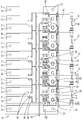
- FIG. 1 is a plan view of a battery module to which a battery wiring module according to Embodiment 1 of the present invention is attached.
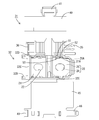
- FIG. 2 is an enlarged plan view of one housing unit portion of the battery wiring module.
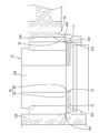
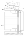
- 3 is a cross-sectional view taken along the line AA in FIG. 4 is a cross-sectional view taken along the line BB of FIG.
- FIG. 5 is a bottom view of the same.
- FIG. 6 is a plan view of the storage unit. 7 is a cross-sectional view taken along the line CC of FIG.
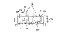
- FIG. 8 is a perspective view of the storage unit.
- FIG. 9 is an enlarged perspective view of the elastic engagement piece portion.
- FIG. 10 is an enlarged plan view of one housing unit portion of the battery wiring module according to the second embodiment.
- 11 is a cross-sectional view taken along the line DD of FIG.
- the battery wiring module 20 of the present embodiment is attached to a single battery group in which a plurality of single batteries 11 are arranged to constitute the battery module 10.
- the battery module 10 is used as a drive source for a vehicle such as an electric vehicle or a hybrid vehicle.
- the upper side of FIG. 1 is the front side
- the lower side is the rear side
- the left-right direction is the connection direction
- the front side of the page is the upper side
- the back side of the page is the lower side.
- the battery module 10 includes, for example, a plurality of unit cells 11 (corresponding to a unit cell group) arranged side by side and a battery wiring module 20 attached to the plurality of unit cells 11. It is prepared for.
- the unit cell 11 has a pair of electrode terminals 12 and 13 projecting from both front and rear ends of a predetermined surface (upper surface) of a rectangular parallelepiped main body in which a power generation element (not shown) is accommodated.
- One of the electrode terminals 12 and 13 is a positive terminal, and the other is a negative terminal. Screw threads are formed on the peripheral surfaces of the electrode terminals 12 and 13.
- the unit cells 11 are arranged side by side so that the front and rear direction of the adjacent unit cells 11 are opposite to each other, whereby the polarities of the adjacent electrode terminals 12 and 13 are different (the positive electrode and the negative electrode are arranged side by side). (Alternately).
- the plurality of unit cells 11 are fixed by a holder (not shown) so as to constitute a group of unit cells arranged side by side.
- Battery wiring module Two sets of battery wiring modules 20 are attached so as to follow the two rows of electrode terminals 12 and 13 grouped side by side at the front and rear ends (upper and lower ends in FIG. 1) of the unit cell group. In the figure, only the rear one of the two sets is shown.
- the battery wiring module 20 includes a plurality of bus bars 21 (corresponding to connecting members) that connect between electrode terminals 12 and 13 that are adjacent to each other in an insulating protector 30 made of synthetic resin.
- a plurality of voltage detection terminals 25 for detecting the voltage of the unit cells 11 stacked on each bus bar 21 are accommodated.
- the bus bar 21 is made of metal such as copper, copper alloy, stainless steel (SUS), and aluminum, and has a length corresponding to the dimension between the electrode terminals 12 and 13 of the adjacent unit cells 11 as shown in FIGS.
- a pair of through-holes 22 is formed, through which the electrode terminals 12 and 13 can be inserted.
- the shape of the through hole 22 is an oval shape whose longitudinal direction is the connection direction, and can absorb a dimensional error between the electrode terminals 12 and 13 due to a dimensional tolerance or an assembly tolerance of each unit cell 11. It has become.
- the voltage detection terminal 25 superimposed on the bus bar 21 includes a rectangular flat plate portion 26 (corresponding to a detection member) and a crimping portion 27 provided so as to protrude from the flat plate portion 26.
- a detection wire 23 for detecting the voltage of the battery 11 is crimped.
- An insertion hole 28 that penetrates one of the through holes 22 of the bus bar 21 and through which the corresponding one of the electrode terminals 12 (13) can be inserted is formed through the central portion of the flat plate portion 26.
- the detection electric wires 23 connected to the voltage detection terminals 25 are collected in an electric wire receiving groove 33 of an insulation protector 30 described later and connected to a battery ECU (not shown) provided at a position on the right side of FIG.
- the battery ECU is equipped with a microcomputer, an element, and the like, and has a function of detecting the voltage, current, temperature, etc. of the unit cell 11 and performing monitoring control of each unit cell 11 and the like. The structure is made.
- the insulation protector 30 includes a plurality (five in this embodiment) of accommodation units 31 connected in the left-right direction.
- the arrangement direction of the accommodation units 31 matches the arrangement direction of the detection wires 23, and further matches the arrangement direction of the cells 11 in this embodiment.
- the housing unit 31 is made of a synthetic resin, and as shown in FIG. 2, the housing unit 32 that houses the bus bar 21 and the voltage detection terminal 25 superimposed on the bus bar 21 and the housing portion 32 are provided in the left-right direction. Are opened, and a wire lead-out groove 34 communicating with the housing portion 32 and the wire housing groove 33 is provided.
- the accommodating portion 32 has a box shape that is long in the left-right direction (connection direction) in order to accommodate the bus bar 21, and the surrounding wall frame portion 32 ⁇ / b> A (inner side) that surrounds the three sides around the accommodated bus bar 21 (other than the right side in FIG. 2). 2), a side open end 32B into which the bus bar 21 can be laterally inserted from the right side of FIG. 2, and a bottom plate 32C on which the accommodated bus bar 21 is placed.
- the wall surfaces along the left-right direction are a front side wall surface 32D and a rear side wall surface 32E, respectively.
- the upper end of the surrounding wall frame portion 32A is an upper open end 32F (see FIGS.
- a plurality of bus bar pressers 32G for restricting the vertical movement of the horizontally inserted bus bar 21 protrude from the front side wall surface 32D and the rear side wall surface 32E of the surrounding wall frame portion 32A.
- the wire lead-out groove 34 has a concave shape extending in the front-rear direction, and communicates with the housing portion 32 through the front side wall surface 32D of the wall surface along the left-right direction of the surrounding wall frame portion 32A in the housing portion 32, and the wire housing groove 33.
- the rear groove wall portion 33 ⁇ / b> B is also penetrated and communicated with the wire receiving groove 33.
- the wire lead-out groove 34 guides the crimping portion 27 of the voltage detection terminal 25 and the sensing wire 23 crimped thereto from the housing portion 32 to the wire housing groove 33.
- the electric wire accommodation groove 33 is configured to have a concave cross section by a pair of groove wall portions 33A extending in the left-right direction, and constitutes one groove communicating in the left-right direction by connecting the accommodation units 31 to each other.
- the electric wire receiving groove 33 bends each detection electric wire 23 led out from the electric wire outlet groove 34 of each accommodation unit 31 at a substantially right angle, whereby a plurality of detection electric wires 23 are formed along the extending direction of the electric wire accommodation groove 33. And is led out to the left on the battery ECU side described above.
- the electric wire receiving groove 33 is integrally provided with a first lid portion 40 from the side surface of the front groove wall portion 33 ⁇ / b> C of the groove wall portion 33 ⁇ / b> A via a hinge. It has been.
- the first lid portion 40 is rotatable about the hinge as an axis, and can cover the entire wire receiving groove 33 from above when the lid is closed.
- a lead-out groove cover 41 that covers the wire lead-out groove 34 from above is extended from the first cover 40 when the cover is closed.
- a pair of first locking pieces 42 project from the lead-out groove cover 41, and the first cover pieces 40 are locked at both sides in the width direction of the wire lead-out groove 34. Is provided with a first locking groove 43 that maintains the closed state.
- the housing portion 32 is integrally provided with a second lid portion 45 via a hinge from the side surface of the rear side wall surface 32 ⁇ / b> E of the surrounding frame portion 32 ⁇ / b> A. .
- the second lid portion 45 is rotatable about the hinge as an axis center, and can cover the entire housing portion 32 and the wire lead-out groove 34 when the lid is closed.
- a pair of second locking pieces 46 project from the lower surface of the second lid 45 when the lid is closed.
- a second locking groove 47 for locking the second locking piece 46 is provided on the outer side of the first locking groove 43 located on both sides of the wire lead-out groove 34.
- the wire lead-out groove 34 is formed by the lead-out groove lid 41 and the second lid 45 of the first lid 40. It will be in the state where the lid was doubled. Therefore, by locking the second locking piece 46 in the second locking groove 47, it is possible to keep the upper portion of the entire storage unit 31 covered with the first lid portion 40 and the second lid portion 45. it can.
- FIGS. 2, 5, 6, and 8 on the left side of the second locking groove 47 located on the left hand side of the wire lead-out groove 34, there is a coupling member that protrudes in the connection direction (left-right direction).
- a claw 35 is provided on the right side of the second locking groove 47 located on the right hand side of the wire lead-out groove 34.
- a coupled recessed portion 36 for coupling with which the coupling engaging claw 35 of the receiving unit 31 on the mating side can be engaged. It has been.
- the coupling engaging claw 35 is composed of a pair of elastic pieces and is configured to be able to bend and deform in a direction approaching each other.
- the coupling engagement recessed portion 36 has a concave shape that allows the coupling engagement claw 35 to be engaged by being inserted into the coupling engagement claw 35 while being bent and deformed and elastically restored.
- an engaging claw 48 for connecting the lid part protrudes from the lower left end of the second lid part 45.
- a lid-portion engaged hole 49 that can engage with a lid-portion engaging claw 48 of the receiving unit 31 that is the counterpart is provided.
- the lid coupling engagement holes 49 have a ring shape penetrating in the connecting direction.
- the configuration according to the main part of the present embodiment will be described in detail.
- the accommodated bus bar 21 is prevented from coming off in the left-right direction, and is inserted from above.
- the elastic engagement piece 50 which latches is provided.
- the elastic engagement piece 50 is formed on the front side wall surface 32D corresponding to the position where the bus bar 21 and the voltage detection terminal 25 are accommodated in an overlapping manner.
- the front side wall surface 32D has a cantilever shape in which two portions are cut in parallel (notched) from the lower end to a substantially central position in the vertical direction, and is elastic.
- the engaging piece 50 is integrally formed with the front side wall surface 32D.
- the side surface of the elastic engagement piece 50 facing the housing portion 32 is located above the bus bar lock claw 51 (corresponding to the connection member lock claw).
- the detection terminal lock claws 52 (corresponding to the detection member lock claws) are juxtaposed so as to be positioned.
- the lock claws 51 and 52 are partially overlapped in the vertical direction. In the horizontal direction, the detection terminal lock claws 52 are slightly shifted to the left with respect to the bus bar lock claws 51. ing.
- the bus bar lock pawl 51 has a triangular shape in a top view in which the side open end 32B side into which the bus bar 21 is horizontally inserted is inclined.
- the nail 51 is housed in the housing portion 32 while being pushed out of the housing portion 32.
- the bus bar lock pawl 51 that is once retracted out of the accommodating portion 32 by bending deformation is provided in a dependency portion 21A that is notched at a corresponding position of the bus bar 21, as shown in FIGS. By returning to elasticity, the bus bar 21 can be locked in the left-right direction so that it cannot be pulled out.
- the voltage detection terminal 25 is also formed with a cutout recess 26A that avoids the bus bar lock pawl 51. This is because, as shown in FIG. 3, the voltage detection terminal 25 accommodated in a state of being superimposed on the bus bar 21 is positioned on the side of the bus bar lock claw 51.
- the detection terminal lock claw 52 having a rectangular shape in a top view is positioned on the elastic engagement piece 50 that is elastically deformed in the front-rear direction.
- the detection terminal lock claw 52 is pushed out of the housing portion 32 by the side edge of the voltage detection terminal 25.
- the detection terminal lock claw 52 is elastically restored and the detection terminal lock claw 52 is projected on the voltage detection terminal 25.
- the two lock claws 51 and 52 provided on one elastic engagement piece 50 prevent the bus bar 21 from coming off in the left-right direction, and the voltage detection terminal 25 can move in the up-down direction. Be regulated. Since the flat plate portion 26 of the voltage detection terminal 25 is provided with the avoidance recess 26A, it is placed on the bus bar 21 while avoiding the bus bar lock pawl 51.
- the bus bar 21 is laterally inserted into the accommodating portion 32 from the side open end 32B.
- the bus bar lock pawl 51 of the elastic engagement piece 50 is bent and deformed to allow the bus bar 21 to be inserted, and then elastically restored to lock the bus bar 21 on the receiving portion 21A of the bus bar 21.
- the claw 51 is engaged, the bus bar 21 is locked so that it cannot be pulled out.
- the voltage detection terminal 25 is fitted from above the accommodating portion 32 onto the accommodated bus bar 21, and the detection electric wire 23 crimped to the voltage detection terminal 25 from the electric wire outlet groove 34 to the electric wire accommodation groove 33.
- the detection terminal lock claw 52 of the elastic engagement piece 50 is bent and deformed, allowing the voltage detection terminal 25 to be inserted, and then returning elastically to detect the voltage.
- the voltage detection terminal 25 is restricted from moving up and down.
- the accommodation units 31 are connected to each other.
- the adjacent coupling engaging claws 35 are engaged with the coupling engagement recessed portions 36, and the adjacent lids are similarly formed.
- the part coupling engaging claws 48 are inserted into the lid part coupling engaged holes 49.
- the electrode terminals 12 and 13 of the cell 11 corresponding to the through holes 22 of the bus bars 21 and the insertion holes 28 of the voltage detection terminals 25 communicating therewith are inserted.
- a nut (not shown) is screwed into the through hole 22 or the electrode terminals 12 and 13 inserted through the through hole 22 and the insertion hole 28 and tightened.
- the electrode terminals 12 and 13 and the voltage detection terminal 25 projecting into the same accommodating portion 32 through the bus bar 21 are electrically connected.
- the lock claws 51 and 52 capable of individually locking the bus bar 21 and the voltage detection terminal 25 are formed on the same elastic engagement piece 50, so that a plurality of locks are formed. Since the nail
- the elastic engagement piece 50 is formed by cutting out the surrounding frame portion 32A (in this embodiment, the front side wall surface 32D) of the accommodation portion 32, for example, the elastic engagement piece is a separate component from the accommodation portion. Compared with the case of forming by, the number of parts does not increase and the cost can be reduced.
- the bus bar 21 is inserted horizontally from the side open end 32B, and the voltage detection terminal 25 is inserted from the upper open end 32F. Even if it is the structure accommodated in, it is possible to form each lock nail
- the battery wiring module of the present embodiment is different from the first embodiment in the shapes of the bus bar lock claw and the detection terminal lock claw 72 of the elastic engagement piece 70. Since other configurations are the same as those in the first embodiment, the same reference numerals are given and description thereof is omitted.
- An elastic engagement piece 70 is provided in the accommodating portion 61 of the accommodating unit 60.
- the elastic engagement piece 70 is formed on the front side wall surface 64 corresponding to the position where the bus bar 62 and the voltage detection terminal 63 are accommodated in an overlapping manner. That is, one cantilevered elastic engagement piece 70 is integrally formed by cutting the front side wall surface 64 that is a part of the surrounding frame portion from below.
- a detection terminal lock claw 72 and a bus bar lock claw are projected in a vertically overlapping manner on the side surface of the one elastic engagement piece 70 facing the housing 61. .
- the bus bar lock claw not shown is engaged with the bus bar lock claw which is elastically returned to the not-shown dependency portion formed on the bus bar 62 while being pushed away by the bus bar 62 which is horizontally inserted, as in the first embodiment. Thus, it is possible to prevent it from coming off.
- the detection terminal lock claw 72 has a top view shape as shown in FIG.
- the detection terminal lock claw 72 is pushed out of the accommodating portion 61 by the side edge of the voltage detection terminal 63 as in the first embodiment.
- the detection terminal lock claw 72 is elastically restored so that the detection terminal lock claw 72 protrudes on the voltage detection terminal 63.
- the detection bar lock claw 72 and the bus bar lock claw provided on one elastic engagement piece 70 prevent the bus bar 62 from coming off in the left-right direction, and the voltage detection terminal 63 in the vertical direction. Movement to is regulated.
- the detection terminal lock claw 72 and the bus bar lock claw are formed at substantially the same position in the left-right direction as compared with the first embodiment.
- the width of the piece 70 can be reduced. According to such a configuration, it is possible to save space while maintaining the functions of the elastic engagement piece 70, the detection terminal lock claw 72, and the bus bar lock claw.
- the bus bars 21 and 62 that are connection members are horizontally placed in the housing portions 32 and 61, and the voltage detection terminals 25 and 63 that are detection members are connected from the upper open ends of the housing portions 32 and 61.
- a detection member may be horizontal insertion similarly to a connection member, and the structure by which both a connection member and a detection member are inserted from the upper part of an accommodating part may be sufficient. In this case, it can be applied by changing the shape such as changing the overhang length of each lock claw.
- the electrode terminals 12 and 13 of the unit cell 11 are configured to have a rod-shaped shaft portion in which a thread is formed on the peripheral surface thereof.
- the terminal may be nut-shaped and fastened using a separate bolt.
- the number of single cells 11 constituting the battery module 10 is not limited to the number in the above embodiment. Further, the shape of the battery wiring module 20 can be arbitrarily set according to the number of the cells 11.
- the first lid 40 covers the wire receiving groove 33 and the second lid 45 covers the receiving portion 32 and the wire lead-out groove 34.
- the present invention is not limited to this. It may have either one of a 1st cover part and a 2nd cover part, and a 1st cover part and a 2nd cover part may be integral.
- the part which each cover part covers is not limited, for example, the 2nd cover part may cover all the accommodating parts, the electric wire outlet grooves, and the electric wire accommodating grooves, or covers a part thereof. Also good.
- the pair of first locking pieces 42 protrudes from the lead-out groove lid portion 41, and the pair of second locking pieces 46 similarly protrude from the second lid portion 45.
- the latching means for maintaining each cover part in a closed state is not limited to this.
- one or three or more first and second locking pieces may be provided.
- Electrode terminal 20 Battery wiring module 21, 62: Bus bar (connection member) 21A: Dependency part 23: Detection electric wire 25, 63: Voltage detection terminal (detection member) 26: flat plate portion 26A: avoidance recess 30: insulation protector 31, 60: housing unit 32, 61: housing portion 32A: surrounding frame portion (inner wall) 32B: Side open end 32C: Bottom plate 32D: Front side wall surface 32E: Rear side wall surface 32F: Upper open end 32G: Bus bar presser 50, 70: Elastic engagement piece 51: Bus bar lock claw (connection member lock claw) 52, 72: Detection terminal lock claw (detection member lock claw)
Landscapes
- Chemical & Material Sciences (AREA)
- Chemical Kinetics & Catalysis (AREA)
- Electrochemistry (AREA)
- General Chemical & Material Sciences (AREA)
- Engineering & Computer Science (AREA)
- Manufacturing & Machinery (AREA)
- Connection Of Batteries Or Terminals (AREA)
- Battery Mounting, Suspending (AREA)
- Secondary Cells (AREA)
Abstract
Description
本発明の実施形態1を図1ないし図9によって説明する。本実施形態の電池用配線モジュール20は、図1に示すように、単電池11が複数個並べられた単電池群に取り付けられて電池モジュール10を構成する。この電池モジュール10は、例えば、電気自動車やハイブリット自動車等の車両の駆動源として使用される。以下、図1の上側を前側、下側を後側、左右方向を接続方向、紙面手前側を上側、紙面奥側を下側として説明する。
電池モジュール10は、図1に示すように、例えば横並びに配列された複数個の単電池11(単電池群に相当する)と、複数個の単電池11に取り付けられる電池用配線モジュール20とを備えて構成されている。
単電池11は、内部に図示しない発電要素が収容された直方体状の本体部の所定の面(上面)の前後両端には、一対の電極端子12,13が突設されている。電極端子12,13の一方は正極端子であって、他方は負極端子である。電極端子12,13の周面にはネジ山が形成されている。各単電池11は、隣り合う単電池11の前後方向の向きが互いに逆向きとなるように横並びに配置されることで、隣り合う電極端子12,13の極性が異なる(正極と負極が横並び方向に交互となる)構成とされている。これら複数個の単電池11は、横並び状態となった単電池群を構成するように図示しない保持具によって固定されている。
電池用配線モジュール20は、単電池群の前後両端(図1の上下両端)において横並びとなっている二列の電極端子12,13群に沿うように二組が取り付けられている。同図では、二組のうち後側のもののみが図示されている。
バスバー21は、銅、銅合金、ステンレス鋼(SUS)、アルミニウム等の金属からなり、図1及び図2に示すように、隣り合う単電池11の電極端子12,13間の寸法に応じた長さの板状をなし、電極端子12,13を挿通可能な通し孔22が一対形成されている。この通し孔22の形状は、接続方向を長手方向とする長円形状をなしていて、各単電池11の寸法公差や組付公差に起因する電極端子12,13間の寸法誤差を吸収できるようになっている。
バスバー21上に重ね合わされる電圧検知端子25は、方形状の平板部26(検知部材に相当する)と、平板部26から突出して設けられた圧着部27を備え、圧着部27には各単電池11の電圧を検知する検知電線23が圧着されている。平板部26の中心部には、バスバー21のどちらか一方の通し孔22に連通し、これに対応する一方の電極端子12(13)を挿通可能な挿通孔28が貫通形成されている。
絶縁プロテクタ30は、図1に示すように、左右方向に連結された複数(本実施形態では5つ)の収容ユニット31からなる。収容ユニット31の並び方向は検知電線23の配索方向に一致し、本実施形態では、更に単電池11の並び方向に一致する。
収容ユニット31は、合成樹脂製であって、図2に示すように、バスバー21及びそれに重ね合わされる電圧検知端子25を収容する収容部32と、収容部32に平行して設けられ、左右方向が開放された電線収容溝33と、収容部32と電線収容溝33とに連通する電線導出溝34とが設けられている。
収容部32は、バスバー21を収容すべく左右方向(接続方向)が長い箱形をなしており、収容されたバスバー21周りの三方(図2の右方以外)を囲う囲壁枠部32A(内側壁に相当する)と、図2の右方からバスバー21を横入れ可能な側部開放端32Bと、収容されたバスバー21が載置される底板32Cとを備えている。囲壁枠部32Aのうち、左右方向に沿う壁面は、それぞれ前側壁面32D、後側壁面32Eとされている。囲壁枠部32Aの上端は、上部開放端32Fとされ(図7及び図8参照)、電圧検知端子25を上方から収容可能なように、収容部32の上部が外部に開放された態様をなしている。そして、囲壁枠部32Aの、前側壁面32D及び後側壁面32Eからは、横入れされたバスバー21の上下方向の移動を規制するバスバー押さえ32Gが内側に向かって複数突設されている。
電線導出溝34は、前後方向に延びる凹状をなし、収容部32における囲壁枠部32Aのうち、左右方向に沿う壁面の前側壁面32Dを貫通して収容部32に連通するとともに、電線収容溝33の溝壁部33Aのうち、後側溝壁部33Bを同じく貫通して当該電線収容溝33に連通した態様をなしている。この電線導出溝34は、電圧検知端子25の圧着部27及びそれに圧着された検知電線23を収容部32から電線収容溝33へと導出する。
電線収容溝33は、左右方向に延びる一対の溝壁部33Aによって断面凹状に構成され、収容ユニット31同士を連結することで、左右方向に連通する1本の溝を構成する。この電線収容溝33は、各収容ユニット31の電線導出溝34から導出された各検知電線23を略直角に屈曲させることで、当該電線収容溝33の延設方向に沿って複数の検知電線23を収容し、前述した電池ECU側となる左方へと導出させる。
さて、電線収容溝33には、図1及び図2、図8に示すように、その溝壁部33Aの前側溝壁部33Cの側面からはヒンジを介して第1蓋部40が一体に設けられている。第1蓋部40は、ヒンジを軸中心として回動可能とされており、閉蓋時に電線収容溝33全体をその上方から覆うことが可能とされている。この第1蓋部40からは、更に閉蓋時に電線導出溝34をその上方から覆う導出溝用蓋部41が延設されている。導出溝用蓋部41には、一対の第1係止片42が突設されており、電線導出溝34の幅方向両側にこの第1係止片42を係止させて第1蓋部40を閉蓋状態に維持する第1係止溝43が設けられている。
一方、収容部32には、図1及び図2、図8に示すように、囲壁枠部32Aの後側壁面32Eの側面からはヒンジを介して第2蓋部45が一体に設けられている。第2蓋部45は、ヒンジを軸中心として回動可能とされており、閉蓋時に収容部32全体及び電線導出溝34を覆うことが可能とされている。第2蓋部45のうち、閉蓋時に下側となる面からは、図1及び図2、図8に示すように、一対の第2係止片46が突設されている。そして、電線導出溝34の両側部に位置する第1係止溝43のさらに外側方には、第2係止片46を係止する第2係止溝47が設けられている。第1蓋部40を閉蓋状態にしたのち、第2蓋部45を閉蓋状態とすると、電線導出溝34は第1蓋部40の導出溝用蓋部41と第2蓋部45とで二重に蓋をされた状態となる。よって、第2係止片46を第2係止溝47に係止することで、収容ユニット31全体の上部をこれら第1蓋部40及び第2蓋部45で覆った状態に維持することができる。
次に、本発明の実施形態2を図10及び図11によって説明する。本実施形態の電池用配線モジュールは、実施形態1とは、弾性係合片70のバスバー用ロック爪と検知端子用ロック爪72の形状が相違する。他の構成については、実施形態1と同様であるため、同符号を付して説明を省略する。
本発明は上記記述及び図面によって説明した実施形態に限定されるものではなく、例えば次のような実施形態も本発明の技術的範囲に含まれる。
11:単電池
12,13:電極端子
20:電池用配線モジュール
21,62:バスバー(接続部材)
21A:係り受け部
23:検知電線
25,63:電圧検知端子(検知部材)
26:平板部
26A:回避凹部
30:絶縁プロテクタ
31,60:収容ユニット
32,61:収容部
32A:囲壁枠部(内側壁)
32B:側部開放端
32C:底板
32D:前側壁面
32E:後側壁面
32F:上部開放端
32G:バスバー押さえ
50,70:弾性係合片
51:バスバー用ロック爪(接続部材用ロック爪)
52,72:検知端子用ロック爪(検知部材用ロック爪)
Claims (3)
- 正極及び負極の電極端子を有する単電池を複数個並べてなる単電池群に取り付けられる電池用配線モジュールであって、
前記電極端子間を接続する接続部材と、
前記単電池群の状態を検出するために前記接続部材に重ね合わされた状態で前記電極端子に接続される検知部材と、
前記接続部材及び前記検知部材を収容する収容部及び前記検知部材に連なる検知電線を前記収容部から導出する電線導出溝を備える絶縁プロテクタと、
前記収容部に形成されて、弾性変形する弾性係合片と、
前記弾性係合片に形成されて前記接続部材を係止する接続部材用ロック爪と、
前記弾性係合片に更に形成されて前記検知部材を係止する検知部材用ロック爪と、を備えた電池用配線モジュール。 - 前記弾性係合片は、前記収容部の内側壁を切り欠いて形成され、
接続部材用ロック爪及び検知部材用ロック爪は、前記接続部材及び前記検知部材の重畳方向に間隔をあけて、前記弾性係合片から突設されている請求項1に記載の電池用配線モジュール。 - 前記絶縁プロテクタは前記検知電線の配索方向に収容ユニットを複数個連結して構成されており、
前記収容部は、取り付けられる単電池群側とは反対方向を開放した上部開放端と、側壁を構成する囲壁枠部のうち前記収容ユニット同士の接続方向における少なくとも一方を開放した側部開放端とを備え、
前記接続部材は前記側部開放端から横入れされ、前記検知部材は前記上部開放端から挿入される請求項1又は請求項2に記載の電池用配線モジュール。
Priority Applications (3)
| Application Number | Priority Date | Filing Date | Title |
|---|---|---|---|
| CN201280052816.8A CN103907221B (zh) | 2011-10-26 | 2012-10-19 | 电池配线模块 |
| US14/353,738 US9209550B2 (en) | 2011-10-26 | 2012-10-19 | Battery wiring module |
| DE112012004507.6T DE112012004507B8 (de) | 2011-10-26 | 2012-10-19 | Batterieverdrahtungsmodul |
Applications Claiming Priority (2)
| Application Number | Priority Date | Filing Date | Title |
|---|---|---|---|
| JP2011-235180 | 2011-10-26 | ||
| JP2011235180A JP5834769B2 (ja) | 2011-10-26 | 2011-10-26 | 電池用配線モジュール |
Publications (1)
| Publication Number | Publication Date |
|---|---|
| WO2013061870A1 true WO2013061870A1 (ja) | 2013-05-02 |
Family
ID=48167702
Family Applications (1)
| Application Number | Title | Priority Date | Filing Date |
|---|---|---|---|
| PCT/JP2012/077068 Ceased WO2013061870A1 (ja) | 2011-10-26 | 2012-10-19 | 電池用配線モジュール |
Country Status (5)
| Country | Link |
|---|---|
| US (1) | US9209550B2 (ja) |
| JP (1) | JP5834769B2 (ja) |
| CN (1) | CN103907221B (ja) |
| DE (1) | DE112012004507B8 (ja) |
| WO (1) | WO2013061870A1 (ja) |
Cited By (10)
| Publication number | Priority date | Publication date | Assignee | Title |
|---|---|---|---|---|
| WO2014203712A1 (ja) * | 2013-06-18 | 2014-12-24 | 住友電装株式会社 | 配線モジュール |
| EP2908361A4 (en) * | 2013-08-28 | 2016-03-16 | Autonetworks Technologies Ltd | WIRING MODULE |
| EP3133672A4 (en) * | 2014-04-17 | 2017-02-22 | Panasonic Intellectual Property Management Co., Ltd. | Bus bar module, battery monitoring module, and battery module |
| CN107534112A (zh) * | 2015-07-09 | 2018-01-02 | 日立汽车系统株式会社 | 电池组件 |
| CN110050361A (zh) * | 2017-05-25 | 2019-07-23 | 株式会社Lg化学 | 电池模块、包括电池模块的电池组以及用于制造电池模块的方法 |
| CN110754006A (zh) * | 2017-06-08 | 2020-02-04 | 矢崎总业株式会社 | 汽车用汇流条模块和电源装置 |
| CN110875457A (zh) * | 2018-08-29 | 2020-03-10 | 住友电装株式会社 | 电池布线模块 |
| JP2021034352A (ja) * | 2019-08-29 | 2021-03-01 | 住友電装株式会社 | 電池配線モジュール |
| CN112448057A (zh) * | 2019-08-29 | 2021-03-05 | 住友电装株式会社 | 电池布线模块 |
| CN115084764A (zh) * | 2022-08-01 | 2022-09-20 | 深圳市泽塔电源系统有限公司 | 一种电池支架结构及其电池组 |
Families Citing this family (30)
| Publication number | Priority date | Publication date | Assignee | Title |
|---|---|---|---|---|
| AU2003248564A1 (en) * | 2002-05-23 | 2003-12-12 | Protectconnect, Inc. | Safety module electrical distribution system |
| JP5772524B2 (ja) * | 2011-11-11 | 2015-09-02 | 株式会社オートネットワーク技術研究所 | 電池配線モジュール |
| JP6186922B2 (ja) * | 2013-06-18 | 2017-08-30 | 住友電装株式会社 | 配線モジュール |
| JP6317898B2 (ja) * | 2013-08-08 | 2018-04-25 | 矢崎総業株式会社 | バスバモジュール |
| JP6330353B2 (ja) * | 2014-02-06 | 2018-05-30 | 株式会社オートネットワーク技術研究所 | 配線モジュール |
| WO2016191250A1 (en) * | 2015-05-22 | 2016-12-01 | Panduit Corp. | Field terminable plug assembly |
| KR102209825B1 (ko) * | 2016-07-21 | 2021-01-29 | 삼성에스디아이 주식회사 | 배터리 모듈 |
| JP6641602B2 (ja) * | 2016-07-22 | 2020-02-05 | 株式会社オートネットワーク技術研究所 | 配線モジュール |
| JP6699464B2 (ja) * | 2016-09-05 | 2020-05-27 | 株式会社オートネットワーク技術研究所 | 接続モジュール |
| JP6587598B2 (ja) * | 2016-11-18 | 2019-10-09 | 矢崎総業株式会社 | 電圧検出用端子の保持構造 |
| JP6794908B2 (ja) * | 2017-04-11 | 2020-12-02 | 住友電装株式会社 | 電池配線モジュール |
| JP6299917B1 (ja) * | 2017-08-09 | 2018-03-28 | 株式会社オートネットワーク技術研究所 | 接続モジュール |
| KR102177694B1 (ko) | 2017-11-06 | 2020-11-11 | 주식회사 엘지화학 | 버스바 어셈블리를 포함하는 배터리 모듈 |
| JP6981234B2 (ja) * | 2017-12-22 | 2021-12-15 | 住友電装株式会社 | バッテリターミナルカバー |
| JP6477858B1 (ja) * | 2017-12-28 | 2019-03-06 | 株式会社オートネットワーク技術研究所 | 接続モジュール |
| JP2019207823A (ja) * | 2018-05-30 | 2019-12-05 | 株式会社オートネットワーク技術研究所 | 配線モジュール、及び蓄電モジュール |
| DE102018114764B4 (de) * | 2018-06-20 | 2020-02-20 | Lisa Dräxlmaier GmbH | Steckbarer modulverbinder, verbindungssystem und verfahren zum elektrisch leitenden verbinden von zumindest zwei batteriemodulen |
| JP7119762B2 (ja) * | 2018-08-22 | 2022-08-17 | トヨタ自動車株式会社 | 接続モジュール |
| JP7001022B2 (ja) * | 2018-08-29 | 2022-02-03 | 住友電装株式会社 | 電池配線モジュール |
| JP6820896B2 (ja) * | 2018-10-16 | 2021-01-27 | 本田技研工業株式会社 | バッテリユニット |
| US20200144579A1 (en) * | 2018-11-01 | 2020-05-07 | Ford Global Technologies, Llc | Electrified vehicle with low profile busbar for high current interfaces, and corresponding method |
| JP7132178B2 (ja) * | 2019-06-18 | 2022-09-06 | 矢崎総業株式会社 | バスバーモジュール |
| JP7205406B2 (ja) * | 2019-07-05 | 2023-01-17 | 株式会社オートネットワーク技術研究所 | 接続モジュール |
| JP2021106088A (ja) * | 2019-12-26 | 2021-07-26 | 住友電装株式会社 | 電池配線モジュール |
| JP7182094B2 (ja) * | 2020-02-27 | 2022-12-02 | 矢崎総業株式会社 | バスバーモジュール |
| JP7078664B2 (ja) * | 2020-04-07 | 2022-05-31 | 矢崎総業株式会社 | バスバーモジュール |
| US20230156967A1 (en) * | 2020-05-21 | 2023-05-18 | Autonetworks Technologies, Ltd. | Circuit assembly |
| JP7355780B2 (ja) * | 2021-04-30 | 2023-10-03 | 矢崎総業株式会社 | 電圧検知ユニット |
| JP7348229B2 (ja) * | 2021-04-30 | 2023-09-20 | 矢崎総業株式会社 | 電圧検知ユニット、及び、蓄電装置 |
| DE102022124988B4 (de) * | 2022-09-28 | 2025-05-15 | Röchling Automotive SE | Sammel-Verbindungsschiene mit Kopplungsabschnitten zur körperlichen Kopplung mehrerer gleichartiger Sammel-Verbindungsschienen |
Citations (3)
| Publication number | Priority date | Publication date | Assignee | Title |
|---|---|---|---|---|
| JP2011018499A (ja) * | 2009-07-08 | 2011-01-27 | Yazaki Corp | 電源装置 |
| JP2011040335A (ja) * | 2009-08-18 | 2011-02-24 | Yazaki Corp | 電源装置 |
| JP2011060675A (ja) * | 2009-09-14 | 2011-03-24 | Yazaki Corp | 電源装置のカバー構造 |
Family Cites Families (9)
| Publication number | Priority date | Publication date | Assignee | Title |
|---|---|---|---|---|
| JP5500336B2 (ja) | 2009-06-23 | 2014-05-21 | 株式会社オートネットワーク技術研究所 | 電池接続アセンブリ |
| WO2011021614A1 (ja) | 2009-08-18 | 2011-02-24 | 矢崎総業株式会社 | 電源装置及び電池接続体 |
| JP5813302B2 (ja) * | 2009-09-07 | 2015-11-17 | 矢崎総業株式会社 | バスバモジュール、及び、このバスバモジュールを備えた電源装置 |
| JP5506307B2 (ja) * | 2009-09-24 | 2014-05-28 | 矢崎総業株式会社 | 電線配索装置 |
| JP5734607B2 (ja) * | 2010-09-16 | 2015-06-17 | 矢崎総業株式会社 | バッテリ接続部材 |
| JP5772524B2 (ja) * | 2011-11-11 | 2015-09-02 | 株式会社オートネットワーク技術研究所 | 電池配線モジュール |
| JP5741948B2 (ja) * | 2011-11-11 | 2015-07-01 | 株式会社オートネットワーク技術研究所 | 電池配線モジュール |
| JP5772525B2 (ja) * | 2011-11-11 | 2015-09-02 | 株式会社オートネットワーク技術研究所 | 電池配線モジュール |
| JP5953051B2 (ja) * | 2012-01-27 | 2016-07-13 | 矢崎総業株式会社 | 電池パック用バスバーモジュール |
-
2011
- 2011-10-26 JP JP2011235180A patent/JP5834769B2/ja not_active Expired - Fee Related
-
2012
- 2012-10-19 DE DE112012004507.6T patent/DE112012004507B8/de not_active Expired - Fee Related
- 2012-10-19 WO PCT/JP2012/077068 patent/WO2013061870A1/ja not_active Ceased
- 2012-10-19 CN CN201280052816.8A patent/CN103907221B/zh not_active Expired - Fee Related
- 2012-10-19 US US14/353,738 patent/US9209550B2/en active Active
Patent Citations (3)
| Publication number | Priority date | Publication date | Assignee | Title |
|---|---|---|---|---|
| JP2011018499A (ja) * | 2009-07-08 | 2011-01-27 | Yazaki Corp | 電源装置 |
| JP2011040335A (ja) * | 2009-08-18 | 2011-02-24 | Yazaki Corp | 電源装置 |
| JP2011060675A (ja) * | 2009-09-14 | 2011-03-24 | Yazaki Corp | 電源装置のカバー構造 |
Cited By (21)
| Publication number | Priority date | Publication date | Assignee | Title |
|---|---|---|---|---|
| JP2015002163A (ja) * | 2013-06-18 | 2015-01-05 | 住友電装株式会社 | 配線モジュール |
| WO2014203712A1 (ja) * | 2013-06-18 | 2014-12-24 | 住友電装株式会社 | 配線モジュール |
| EP2908361A4 (en) * | 2013-08-28 | 2016-03-16 | Autonetworks Technologies Ltd | WIRING MODULE |
| US9397417B2 (en) | 2013-08-28 | 2016-07-19 | Autonetworks Technologies, Ltd. | Wiring module having a voltage detection terminal |
| EP3098878A1 (en) | 2013-08-28 | 2016-11-30 | AutoNetworks Technologies, Ltd. | Wiring module |
| EP3133672A4 (en) * | 2014-04-17 | 2017-02-22 | Panasonic Intellectual Property Management Co., Ltd. | Bus bar module, battery monitoring module, and battery module |
| JPWO2015159524A1 (ja) * | 2014-04-17 | 2017-04-13 | パナソニックIpマネジメント株式会社 | バスバーモジュール、バッテリ監視モジュールおよびバッテリモジュール |
| US10008709B2 (en) | 2014-04-17 | 2018-06-26 | Panasonic Intellectual Property Management Co., Ltd. | Bus bar module, battery monitoring module, and battery module |
| CN107534112B (zh) * | 2015-07-09 | 2020-10-02 | 日本汽车能源株式会社 | 电池组件 |
| CN107534112A (zh) * | 2015-07-09 | 2018-01-02 | 日立汽车系统株式会社 | 电池组件 |
| CN110050361A (zh) * | 2017-05-25 | 2019-07-23 | 株式会社Lg化学 | 电池模块、包括电池模块的电池组以及用于制造电池模块的方法 |
| CN110050361B (zh) * | 2017-05-25 | 2023-04-28 | 株式会社Lg新能源 | 电池模块、包括电池模块的电池组以及用于制造电池模块的方法 |
| CN110754006A (zh) * | 2017-06-08 | 2020-02-04 | 矢崎总业株式会社 | 汽车用汇流条模块和电源装置 |
| CN110754006B (zh) * | 2017-06-08 | 2022-04-08 | 矢崎总业株式会社 | 汽车用汇流条模块和电源装置 |
| CN110875457B (zh) * | 2018-08-29 | 2022-09-02 | 住友电装株式会社 | 电池布线模块 |
| CN110875457A (zh) * | 2018-08-29 | 2020-03-10 | 住友电装株式会社 | 电池布线模块 |
| JP2021034352A (ja) * | 2019-08-29 | 2021-03-01 | 住友電装株式会社 | 電池配線モジュール |
| CN112448057A (zh) * | 2019-08-29 | 2021-03-05 | 住友电装株式会社 | 电池布线模块 |
| JP7207238B2 (ja) | 2019-08-29 | 2023-01-18 | 住友電装株式会社 | 電池配線モジュール |
| CN115084764A (zh) * | 2022-08-01 | 2022-09-20 | 深圳市泽塔电源系统有限公司 | 一种电池支架结构及其电池组 |
| CN115084764B (zh) * | 2022-08-01 | 2024-05-24 | 深圳市泽塔电源系统有限公司 | 一种电池组 |
Also Published As
| Publication number | Publication date |
|---|---|
| JP5834769B2 (ja) | 2015-12-24 |
| CN103907221A (zh) | 2014-07-02 |
| CN103907221B (zh) | 2016-06-15 |
| DE112012004507T5 (de) | 2014-08-28 |
| DE112012004507B8 (de) | 2024-10-02 |
| US9209550B2 (en) | 2015-12-08 |
| DE112012004507B4 (de) | 2023-10-12 |
| JP2013093237A (ja) | 2013-05-16 |
| US20140287622A1 (en) | 2014-09-25 |
Similar Documents
| Publication | Publication Date | Title |
|---|---|---|
| JP5834769B2 (ja) | 電池用配線モジュール | |
| JP5772524B2 (ja) | 電池配線モジュール | |
| JP5975296B2 (ja) | 配線モジュール | |
| US9425520B2 (en) | Battery wiring module | |
| JP5720530B2 (ja) | 電池用配線モジュール | |
| JP5772525B2 (ja) | 電池配線モジュール | |
| EP2706593B1 (en) | Battery wiring module | |
| JP6075150B2 (ja) | 配線モジュール | |
| JP6176126B2 (ja) | 配線モジュールおよび蓄電モジュール | |
| JP5862077B2 (ja) | 電池配線モジュール | |
| JP5418522B2 (ja) | 電池接続アセンブリ及び電池モジュール | |
| JP5787140B2 (ja) | 電池配線モジュール | |
| JP2013016381A (ja) | 電池配線モジュール | |
| JP2011258413A (ja) | 電池接続アセンブリ | |
| EP2908361B1 (en) | Wiring module | |
| JP5673464B2 (ja) | 電池配線モジュール | |
| JP6044495B2 (ja) | 配線モジュール | |
| JP5673465B2 (ja) | 電池配線モジュール | |
| WO2012160981A1 (ja) | 電池配線モジュールおよびその製造方法 | |
| CN106233504A (zh) | 布线模块 | |
| JP5757180B2 (ja) | 電池配線モジュールのカバー、電池配線モジュール及び電池モジュール | |
| JP2012186063A (ja) | 電池接続アセンブリ | |
| JP2014165043A (ja) | 配線モジュール |
Legal Events
| Date | Code | Title | Description |
|---|---|---|---|
| 121 | Ep: the epo has been informed by wipo that ep was designated in this application |
Ref document number: 12843762 Country of ref document: EP Kind code of ref document: A1 |
|
| WWE | Wipo information: entry into national phase |
Ref document number: 14353738 Country of ref document: US |
|
| WWE | Wipo information: entry into national phase |
Ref document number: 1120120045076 Country of ref document: DE Ref document number: 112012004507 Country of ref document: DE |
|
| 122 | Ep: pct application non-entry in european phase |
Ref document number: 12843762 Country of ref document: EP Kind code of ref document: A1 |