WO2013061633A1 - 端子圧着装置 - Google Patents
端子圧着装置 Download PDFInfo
- Publication number
- WO2013061633A1 WO2013061633A1 PCT/JP2012/057926 JP2012057926W WO2013061633A1 WO 2013061633 A1 WO2013061633 A1 WO 2013061633A1 JP 2012057926 W JP2012057926 W JP 2012057926W WO 2013061633 A1 WO2013061633 A1 WO 2013061633A1
- Authority
- WO
- WIPO (PCT)
- Prior art keywords
- terminal
- crimping
- guide
- end side
- continuous
- Prior art date
- Legal status (The legal status is an assumption and is not a legal conclusion. Google has not performed a legal analysis and makes no representation as to the accuracy of the status listed.)
- Ceased
Links
Images



Classifications
-
- H—ELECTRICITY
- H01—ELECTRIC ELEMENTS
- H01R—ELECTRICALLY-CONDUCTIVE CONNECTIONS; STRUCTURAL ASSOCIATIONS OF A PLURALITY OF MUTUALLY-INSULATED ELECTRICAL CONNECTING ELEMENTS; COUPLING DEVICES; CURRENT COLLECTORS
- H01R43/00—Apparatus or processes specially adapted for manufacturing, assembling, maintaining, or repairing of line connectors or current collectors or for joining electric conductors
- H01R43/04—Apparatus or processes specially adapted for manufacturing, assembling, maintaining, or repairing of line connectors or current collectors or for joining electric conductors for forming connections by deformation, e.g. crimping tool
- H01R43/048—Crimping apparatus or processes
- H01R43/055—Crimping apparatus or processes with contact member feeding mechanism
Definitions
- This invention relates to a technique for continuously crimping a terminal to an end of an electric wire.
- a terminal crimping device (terminal crimping applicator) is known as a device for continuously crimping a terminal to an end of an electric wire.
- a terminal crimping apparatus is composed of a feeding mechanism that feeds continuous terminals (strip-shaped members with a plurality of terminals connected) one after another along a defined delivery path, and a crimping die that is moved along a vertical direction. And a crimping mechanism that crimps the terminal and crimps it to the electric wire, and these mechanisms work together to continuously perform the crimping process (see, for example, Patent Document 1).
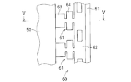
- FIG. 4 is a schematic front view showing a state in which the continuous terminal 60 is regulated by the two guide members 50 and 51
- FIG. 5 is a cross-sectional view taken along the line VV in FIG.
- the first guide member 50 is brought into contact with one end side in the axial direction of the crimping portion 63 with respect to the core wire of each terminal 63, and the second guide member 51 is connected to the continuous terminal 60.
- the movement of the terminal 61 in the axial direction of the continuous terminal 60 is restricted, and the crimping portion 63 of each terminal 61 is guided directly below the crimping die 52. It is possible.
- the dimensional accuracy of the crimping part 63 of each terminal 61 is high, but the other parts (for example, the crimping part 64 etc. for the covering) are the crimping part 63. Therefore, the dimensions other than the crimping portion 63 in each terminal 61 of the continuous terminal 60 vary from lot to lot. As a result, the dimensions from the crimping part 63 to the chain 62 may change for each lot, and the contact position between the continuous terminal 60 and the two guide members 50 and 51 is adjusted each time the lot is changed. Because it is necessary, positioning of the continuous terminal cannot be performed easily.
- an object of the present invention is to enable easy positioning of continuous terminals.
- the terminal crimping apparatus crimps the terminal to the electric wire by crimping one of the terminals connected to the continuous terminal with a crimping die.
- each terminal of the crimping mechanism and the continuous terminal it is brought into contact with one end side in the axial direction of the crimping portion with respect to the core wire of the electric wire, thereby restricting the continuous terminal from moving to one end side in the axial direction.
- a first guide portion that guides the crimping portion of each terminal to a position on the axial center of the crimping die, and the other end side in the axial direction of the crimping portion with respect to the core wire in each terminal.
- a second guide that abuts to restrict the continuous terminal from moving to the other end side in the axial direction and guides the crimping portion of each terminal to a position on the axial center of the crimping die. Department.
- a second aspect is a terminal crimping apparatus according to the first aspect, wherein the first guide part and the second guide part are integrally formed via a connecting member.
- a third aspect is a terminal crimping apparatus according to the second aspect, wherein the connecting member is disposed at a position facing the upper surface of the crimping portion of each terminal.
- the first guide portion is brought into contact with one end side in the axial direction of the crimping portion with respect to the core wire having high dimensional accuracy
- the second guide portion is made to be a core wire having high dimensional accuracy.
- the continuous terminal can be easily positioned by bringing it into contact with the other end side in the axial direction of the crimping portion. Further, since the crimping portion having high dimensional accuracy is brought into contact with the first guide portion and the second guide portion, even when the lot is changed, the contact between the continuous terminal, the first guide portion, and the second guide portion. The continuous terminal can be easily positioned without adjusting the position.
- the first guide portion and the second guide portion can be attached. Error can be reduced. Further, the configuration of the terminal crimping device can be simplified.
- the third aspect it is possible to restrict the continuous terminal from moving in the vertical direction by the connecting member.
- FIG. 1 is a schematic front view showing a terminal crimping apparatus 1.
- the continuous terminals are not shown for easy understanding.
- the direction of the arrow is the sending direction of the continuous terminal.
- FIG. 2 is referred about the continuous terminal 30 and the terminal 31 connected with this.
- the continuous terminal 30 is a band-shaped member in which a plurality of terminals 31 are connected. Specifically, a plurality of terminals 31 are formed on one side of a band-shaped chain band 32 and connected in parallel at equal intervals. . Each terminal 31 is formed with a crimping portion 33 for covering and a crimping portion 34 for core wire. In order to increase the accuracy of the bell mouth amount in the crimping portion 34, the crimping portion 34 is formed with high dimensional accuracy.
- the bell mouth refers to a portion in which the end of the crimping portion 34 is slightly swollen in order to gradually reduce the compression pressure in the radial direction of the electric wire and prevent disconnection at the crimping portion 34 when performing the crimping connection.
- portions other than the crimping portion 34 in each terminal 31 are not required to have a higher dimensional accuracy than the crimping portion 34, and thus are not formed with a higher dimensional accuracy than the crimping portion 34.
- the terminal crimping device 1 includes a crimping mechanism 2 that crimps and fixes an end of an electric wire to a terminal 31 (specifically, a crimping portion 34 of the terminal 31) connected to a continuous terminal 30, and a long length wound in a reel shape. And the feeding mechanism 10 that feeds the continuous terminal 30 and feeds it to the crimping mechanism 2, and the crimping mechanism 2 and the feeding mechanism 10 work together along the delivery path (longitudinal direction of the continuous terminal 30).
- the terminal 31 sent out in this way is configured to perform a step of continuously crimping the terminal 31 to the end of the electric wire.
- the crimping mechanism 2 crimps the terminal 31 to the electric wire by crimping one terminal 31 of the plurality of terminals 31 connected to the continuous terminal 30 with a crimping die (the crimper 5 and the anvil 7).
- the crimping mechanism 2 includes a shank 4 housed in the shank holder 3 so as to be movable up and down, a crimper 5 (an upper die for crimping) disposed at the lower end of the shank 4, and a crimper 5. It mainly includes an anvil 7 (a lower die for pressure bonding) disposed at an opposing position.
- the crimping mechanism 2 includes a cutter (not shown) for cutting the terminal 31 from the chain band 32.
- the crimper 5 arranged in the shank 4 is moved up and down.
- the shank 4 is lowered while the terminal 31 is disposed on the anvil 7, the crimper 5 moves close to the anvil 7, and the crimping of the terminal 31 disposed on the anvil 7 between the crimper 5 and the anvil 7 is performed.
- the part 34 is crimped and crimped to the end of the electric wire.
- the cutter cuts the terminal 31 from the chain band 32.
- the feeding mechanism 10 sends the continuous terminal 30 along the sending path (specifically, sends the terminals 31 one after another) and the path defining unit 11 that regulates the sending path of the continuous terminal 30. And an interlocking mechanism (not shown) that interlocks the movement of the crimping mechanism 2 and the movement of the feeding mechanism 10.
- FIG. 2 is a plan view showing the path defining portion 11, and FIG. 3 is a cross-sectional view taken along line III-III in FIG.
- the path defining unit 11 includes a long plate-like stage 12 extending toward the crimping mechanism 2.
- the upper surface of the stage 12 functions as a guide surface that guides the continuous terminal 30 to the crimping mechanism 2. That is, as shown in FIG. 2, the continuous terminal 30 is placed on the stage 12 with the terminal 31 facing one end of the stage 12 and the chain strip 32 along the side edge on the other end of the stage 12. And is sent in the sending direction (in the direction of the arrow in FIG. 2) under the driving of the sending unit.
- the path defining unit 11 includes a guide member 20 disposed so as to cover a part of the upper surface of the stage 12.
- the guide member 20 is formed in a rectangular shape in plan view, and includes a side wall part 21, a connecting part 22 (connecting member) extending in the horizontal direction from the upper end of the side wall part 21, and a first guide part 23 protruding downward from the connecting part 22. And a second guide portion 24.
- the lower end portion of the side wall portion 21 is attached and fixed to the side end portion (on the crimping portion 34 side) in the longitudinal direction of the stage 12.
- a configuration for fixing the side wall portion 21 to the stage 12 for example, a configuration using screws or the like can be employed.
- the connecting portion 22 is disposed at a position facing the upper surface of the crimping portion 34, and the first guide portion 23 and the second guide portion 24 are arranged on the lower surface of the connecting portion 22 at a constant interval along the longitudinal direction of the connecting portion 22. Are provided. Further, the first guide part 23 and the second guide part 24 are integrally formed via the connecting part 22.
- the connecting portion 22 is disposed above the uppermost position of the continuous terminal 30 (slightly above in the embodiment), and restricts the continuous terminal 30 from being displaced in the vertical direction.
- the first guide portion 23 is brought into contact with one end side in the axial direction of the crimping portion 34 of the terminal 31 to restrict the continuous terminal 30 from moving toward one end side in the axial direction, and the crimper 5 and the anvil. 7 to guide the crimping portion 34 of each terminal 31 to a position on the axis 7 (below the crimper 5).
- the second guide portion 24 is brought into contact with the other end side in the axial direction of the crimping portion 34 to restrict the continuous terminal 30 from moving to the other end side in the axial direction, and the crimper 5 and the anvil 7.
- the crimping portion 34 of each terminal 31 is guided to a position on the axial center (directly below the crimper 5).
- first guide portion 23 and the second guide portion 24 sandwich the both end portions in the axial direction of the crimping portion 34 formed with high dimensional accuracy in order to increase the accuracy of the bell mouth amount in the crimping portion 34, and
- the continuous terminal 30 delivered onto the terminal 12 is regulated so as not to be displaced in the width direction of the stage 12, and the crimping portion 34 of each terminal 31 is moved to a position on the axial center of the crimper 5 and anvil 7 (below the crimper 5).
- the distance between the first guide part 23 and the second guide part 24 is formed to be approximately the same as the dimension in the axial direction of the crimping part 34 of each terminal 31.
- the first guide portion 23 and the second guide portion 24 can be sandwiched from the front-rear direction.
- the continuous terminal 30 With each terminal 31 facing one end of the stage 12 and the chain band 32 facing the other end of the stage 12, the continuous terminal 30 is passed from the upstream side of the delivery path to the lower side of the guide member 20, The continuous terminal 30 is set on the stage 12 so that both end portions in the axial center direction of 34 are sandwiched between the first guide portion 23 and the second guide portion 24.
- the continuous terminal which considered the bell mouth amount in the crimping part 34 of each terminal 31 by pinching the both ends of the axial center direction in the crimping part 34 with the 1st guide part 23 and the 2nd guide part 24. 30 positionings are made.
- the continuous terminal 30 is placed on the stage 12 by slightly lifting the front end side in the width direction of the connecting portion 22 of the guide member 20. May be. In this case, while moving the continuous terminal 30 so that both end portions of the crimping portion 34 in the axial direction are directly below the first guide portion 23 and the second guide portion 24, the front end side in the width direction of the connecting portion 22 is the original height. The both ends of the crimping portion 34 in the axial direction are sandwiched between the first guide portion 23 and the second guide portion 24.
- the guide member may be disposed in a connecting portion of the guide member connected to the side end portion (on the chain 32 side) of the stage 12.
- the first guide part and the second guide part may be separate.
- the first guide portion is disposed at the connecting portion of the guide member connected to the side end portion (crimping portion 34 side) of the stage 12, and the second guide portion is the side end portion (concatenated body) of the stage 12. 32 side) is provided at the connecting portion of the guide member.
- the first guide portion 23 is brought into contact with one end side in the axial direction of the crimp portion 34 with respect to the core wire with high dimensional accuracy
- the second guide portion 24 is By making contact with the other end side in the axial center direction of the crimping part 34 with respect to the core wire with high dimensional accuracy, the positioning of the continuous terminal 30 in consideration of the amount of the bell mouth in the crimping part 34 of each terminal 31 can be easily performed.
- the crimp part 34 with high dimensional accuracy is brought into contact with the first guide part 23 and the second guide part 24, the continuous terminal 30, the first guide part 23, and the second guide part can be used even when the lot is changed.
- the positioning of the continuous terminal 30 in consideration of the amount of the bell mouth can be easily performed without adjusting the contact position with 24.
- first guide portion 23 and the second guide portion 24 are integrally formed via the connecting portion 22, one end side in the axial direction of the crimping portion 34 with respect to the core wire of each terminal 31 and one member, The other end side can be brought into contact with each other, and mounting errors of the first guide part 23 and the second guide part 24 can be reduced. Moreover, the structure of the terminal crimping apparatus 1 can be simplified.
- the connecting portion 22 Since the connecting portion 22 is disposed at a position facing the upper surface of the crimping portion 34 of each terminal 31, the connecting portion 22 can restrict the continuous terminal 30 from moving in the vertical direction.
Landscapes
- Engineering & Computer Science (AREA)
- Manufacturing & Machinery (AREA)
- Manufacturing Of Electrical Connectors (AREA)
Abstract
連続端子の位置決めを簡単に行えるようにすることを目的とする。端子圧着装置は、連続端子に連ねられる複数の端子のうちの一つの端子を、クリンパ及びアンビルで加締めることによって、端子を電線に圧着する圧着機構を備えている。また、電線の芯線に対する圧着部における軸心方向の一端側と当接させて、連続端子が軸心方向の一端側へ移動するのを規制すると共に、クリンパ及びアンビルの軸心上の位置へ各端子の圧着部を案内する第1ガイド部と、芯線に対する圧着部における軸心方向の他端側と当接させて、連続端子が軸心方向の他端側へ移動するのを規制すると共に、クリンパ及びアンビルの軸心上の位置へ各端子の圧着部を案内する第2ガイド部とを備えている。
Description
この発明は、電線の端部に端子を連続的に圧着する技術に関する。
電線の端部に端子を連続的に圧着する装置として、端子圧着装置(端子圧着用アプリケータ)が知られている。一般に、端子圧着装置は、連続端子(複数の端子が連ねられた帯状部材)を繰り出して定められた送出経路に沿って次々と送出する送出機構と、鉛直方向に沿って移動される圧着金型で端子を加締めて電線に圧着する圧着機構とを含んで構成されており、これら各機構が連動して圧着工程を連続的に行うようになっている(例えば、特許文献1参照)。
端子圧着装置においては、圧着金型による圧着位置のばらつきを抑制してベルマウス量を均等にするため、圧着時に各端子における芯線に対する圧着部が圧着金型の真下に位置するように連続端子の載置位置を調整することになる。図4は、2つのガイド部材50,51により連続端子60を規制した状態を示す概略正面図であり、図5は、図4のV-V線断面図である。この場合、図4及び図5に示すように、第1ガイド部材50を各端子63における芯線に対する圧着部63における軸心方向の一端側に当接させると共に、第2ガイド部材51を連続端子60の連鎖体62の外端側に当接させることにより、連続端子60における端子61の軸心方向への移動を規制して、各端子61の圧着部63を圧着金型52の真下に案内することが考えられる。
各端子61の圧着部63におけるベルマウス量の精度を高めるために、各端子61の圧着部63の寸法精度は高いが、それ以外の部分(例えば、被覆に対する圧着部64等)は圧着部63と比べてそれほど寸法精度が要求されていないため、連続端子60の各端子61において圧着部63以外の寸法はロット毎にばらつきがある。その結果、ロット毎に圧着部63から連鎖体62までの寸法が変わる可能性があり、ロットを変更するたびに、連続端子60と2つのガイド部材50,51との当接位置をそれぞれ調整する必要があるため、連続端子の位置決めを簡単に行うことができない。
そこで、本発明は、連続端子の位置決めを簡単に行えることを目的とする。
上記課題を解決するため、第1の態様に係る端子圧着装置は、連続端子に連ねられる複数の端子のうちの一つの端子を、圧着金型で加締めることによって、前記端子を電線に圧着する圧着機構と、前記連続端子の各端子において、前記電線の芯線に対する圧着部における軸心方向の一端側と当接させて、前記連続端子が前記軸心方向の一端側へ移動するのを規制すると共に、前記圧着金型の軸心上の位置へ前記各端子の前記圧着部を案内する第1ガイド部と、前記各端子において、前記芯線に対する前記圧着部における前記軸心方向の他端側と当接させて、前記連続端子が前記軸心方向の他端側へ移動するのを規制すると共に、前記圧着金型の軸心上の位置へ前記各端子の前記圧着部を案内する第2ガイド部とを備えている。
第2の態様は、第1の態様に係る端子圧着装置であって、前記第1ガイド部と前記第2ガイド部とが連結部材を介して一体的に形成されている。
第3の態様は、第2の態様に係る端子圧着装置であって、前記連結部材は前記各端子の前記圧着部の上面と対向する位置に配設されている。
第1の態様に係る端子圧着装置によると、第1ガイド部を、寸法精度の高い芯線に対する圧着部における軸心方向の一端側と当接させると共に、第2ガイド部を、寸法精度の高い芯線に対する圧着部における軸心方向の他端側と当接させることにより、連続端子の位置決めを簡単に行うことができる。また、寸法精度の高い前記圧着部を第1ガイド部と第2ガイド部とで当接させるため、ロットを変更した場合にも、連続端子と第1ガイド部及び第2ガイド部との当接位置を調整することなく、連続端子の位置決めを簡単に行うことができる。
第2の態様によると、1つの部材で、各端子の芯線に対する圧着部における軸心方向の一端側及び他端側を当接させることができるため、第1ガイド部及び第2ガイド部の取付け誤差を低減できる。また、端子圧着装置の構成を簡単にすることができる。
第3の態様によると、連結部材により連続端子が鉛直方向に移動するのを規制することができる。
{実施形態}
以下、実施形態に係る端子圧着装置1について説明する。図1は、端子圧着装置1を示す概略正面図である。ただし、図1においては、説明をわかりやすくするために、連続端子の図示が省略されている。なお、図1において、矢印の方向が連続端子の送出方向である。また、連続端子30及びこれに連ねられる端子31については、図2を参照することとする。
以下、実施形態に係る端子圧着装置1について説明する。図1は、端子圧着装置1を示す概略正面図である。ただし、図1においては、説明をわかりやすくするために、連続端子の図示が省略されている。なお、図1において、矢印の方向が連続端子の送出方向である。また、連続端子30及びこれに連ねられる端子31については、図2を参照することとする。
最初に連続端子30について説明する。連続端子30は、複数の端子31が連ねられた帯状の部材であり、具体的には、帯状の連鎖帯32の片側に複数の端子31が等間隔で並列状に連鎖されて形成されている。各端子31には、被覆に対する圧着部33と、芯線に対する圧着部34が形成されている。圧着部34におけるベルマウス量の精度を高めるために、圧着部34は高い寸法精度で形成されている。
ここで、ベルマウスとは、圧着接続を行う際、電線の径方向の圧縮圧力を除々に軽減し、圧着部34での断線を防ぐために圧着部34の端を若干膨らませた部分のことをいう。なお、各端子31において圧着部34以外の部分に関しては、圧着部34と比べて高い寸法精度が要求されていないため、圧着部34ほど高い寸法精度では形成されていない。
端子圧着装置1は、連続端子30に連ねられる端子31(具体的には、端子31の圧着部34)に電線の端部を圧着固定する圧着機構2と、リール状に巻回された長尺の連続端子30を繰り出して圧着機構2に送給する送給機構10と、を含んでおり、圧着機構2と送給機構10が連動して、送出経路(連続端子30の長手方向)に沿って送出された端子31を電線の端部に連続的に圧着する工程を行う構成となっている。
圧着機構2は、連続端子30に連ねられる複数の端子31のうちの1つの端子31を圧着金型(クリンパ5及びアンビル7)で加締めることによって、端子31を電線に圧着する。圧着機構2は、具体的には、シャンクホルダ3内に昇降移動可能に収容されたシャンク4と、シャンク4の下端に配設されたクリンパ5(圧着用の上金型)と、クリンパ5に対向する位置に配設されたアンビル7(圧着用の下金型)とを主として備える。その他にも、圧着機構2には、連鎖帯32から端子31を裁断するためのカッタ(図示省略)等が含まれる。
圧着機構2においては、シャンク4が昇降移動されることによって、シャンク4に配設されたクリンパ5が昇降移動される。アンビル7上に端子31が配置された状態でシャンク4が降下されると、クリンパ5がアンビル7に近接移動し、クリンパ5とアンビル7との間でアンビル7上に配置された端子31の圧着部34が加締められて電線の端部と圧着される。なお、これと共に、カッタが当該端子31を連鎖帯32から切断する。
送給機構10は、連続端子30の送出経路を規定する経路規定部11と、送出経路に沿って連続端子30を送出する(具体的には、端子31を1つずつ次々と送出する)送出部(図示省略)と、圧着機構2の動きと送給機構10の動きとを連動させる連動機構(図示省略)とを主として備える。
次に、経路規定部11について説明する。図2は、経路規定部11を示す平面図であり、図3は、図2のIII-III線断面図である。経路規定部11は、圧着機構2に向かって延在する長尺板状のステージ12を備える。ステージ12は、その上面が連続端子30を圧着機構2に導くガイド面として機能する。すなわち、図2に示すように、連続端子30は、端子31をステージ12の一端側に向け、連鎖帯32をステージ12の他端側の側縁に沿わせた状態で、ステージ12上に載置され、送出部の駆動を受けて送出方向(図2において矢印の方向)に送出される。
また、経路規定部11は、ステージ12の上面の一部を覆うように配設されたガイド部材20を備える。ガイド部材20は、平面視矩形状に形成され、側壁部21と、側壁部21の上端から水平方向に延びる連結部22(連結部材)と、連結部22から下方に突出する第1ガイド部23及び第2ガイド部24とを有する。ステージ12の長手方向の側端部(圧着部34側)に側壁部21の下端部が取付固定されている。ステージ12に対する側壁部21の取付固定の構成としては、例えばビス等を利用した構成等を採用できる。
連結部22は圧着部34の上面と対向する位置に配設され、連結部22の下面には、第1ガイド部23及び第2ガイド部24が連結部22の長手方向に沿って一定の間隔を設けて配設されている。また、第1ガイド部23及び第2ガイド部24は、連結部22を介して一体的に形成されている。連結部22は、連続端子30における最上位位置よりも上方(実施形態においては僅かに上方)に配設されており、連続端子30が鉛直方向に位置ずれしないように規制する。
第1ガイド部23は、端子31の圧着部34における軸心方向の一端側と当接させて、連続端子30が前記軸心方向の一端側へ移動しないように規制すると共に、クリンパ5及びアンビル7の軸心上の位置(クリンパ5の真下)へ各端子31の圧着部34を案内するものである。
第2ガイド部24は、圧着部34における軸心方向の他端側と当接させて、連続端子30が前記軸心方向の他端側へ移動するのを規制すると共に、クリンパ5及びアンビル7の軸心上の位置(クリンパ5の真下)へ各端子31の圧着部34を案内するものである。
すなわち、第1ガイド部23及び第2ガイド部24は、圧着部34におけるベルマウス量の精度を高めるために高い寸法精度に形成された圧着部34における軸心方向の両端部を挟み込んで、ステージ12上に送出される連続端子30がステージ12の幅方向に位置ずれしないように規制すると共に、クリンパ5及びアンビル7の軸心上の位置(クリンパ5の真下)へ各端子31の圧着部34を案内する。
第1ガイド部23と第2ガイド部24との間隔は、各端子31の圧着部34における軸心方向の寸法と略同じ寸法に形成されており、圧着部34における軸心方向の両端部を、第1ガイド部23と第2ガイド部24とで前後方向から挟み込めるようになっている。
次に、ステージ12に連続端子30をセットする方法について説明する。各端子31をステージ12の一端側に向けると共に連鎖帯32をステージ12の他端側に向けた状態で、連続端子30を送出経路の上流側からガイド部材20の下側に通して、圧着部34における軸心方向の両端部を第1ガイド部23と第2ガイド部24とで挟み込むようにして、連続端子30をステージ12にセットする。このように、第1ガイド部23と第2ガイド部24とで、圧着部34における軸心方向の両端部が挟み込まれることにより、各端子31の圧着部34におけるベルマウス量を考慮した連続端子30の位置決めがなされる。
また、ガイド部材20の連結部22が弾性力を有する部材により形成されている場合は、ガイド部材20の連結部22の幅方向先端側を少し持ち上げて、連続端子30をステージ12上に載置してもよい。この場合、圧着部34における軸心方向の両端部が第1ガイド部23と第2ガイド部24の真下になるように連続端子30を動かしながら連結部22の幅方向先端側を元の高さに下ろすことにより、第1ガイド部23と第2ガイド部24とで、圧着部34における軸心方向の両端部が挟み込まれる。
なお、ガイド部材は、ステージ12の側端部(連鎖体32側)に連結されたガイド部材の連結部に配設されてもよい。また、第1ガイド部と第2ガイド部は別体であってもよい。この場合、第1ガイド部は、ステージ12の側端部(圧着部34側)に連結されたガイド部材の連結部に配設され、第2ガイド部は、ステージ12の側端部(連鎖体32側)に連結されたガイド部材の連結部に配設される。
以上のように構成された端子圧着装置1によると、第1ガイド部23を、寸法精度の高い芯線に対する圧着部34における軸心方向の一端側と当接させると共に、第2ガイド部24を、寸法精度の高い芯線に対する圧着部34における軸心方向の他端側と当接させることにより、各端子31の圧着部34におけるベルマウス量を考慮した連続端子30の位置決めを簡単に行うことができる。また、寸法精度の高い圧着部34を第1ガイド部23と第2ガイド部24とで当接させるため、ロットを変更した場合にも、連続端子30と第1ガイド部23及び第2ガイド部24との当接位置を調整することなく、前記ベルマウス量を考慮した連続端子30の位置決めを簡単に行うことができる。
第1ガイド部23と第2ガイド部24とが連結部22を介して一体的に形成されているため、1つの部材で、各端子31の芯線に対する圧着部34における軸心方向の一端側及び他端側を当接させることができ、第1ガイド部23及び第2ガイド部24の取付け誤差を低減できる。また、端子圧着装置1の構成を簡単にすることができる。
連結部22は各端子31の圧着部34の上面と対向する位置に配設されているため、連結部22により連続端子30が鉛直方向に移動するのを規制することができる。
以上のようにこの発明は詳細に説明されたが、上記した説明は、すべての局面において、例示であって、この発明がそれに限定されるものではない。例示されていない無数の変形例が、この発明の範囲から外れることなく想定され得るものと解される。
Claims (3)
- 連続端子に連ねられる複数の端子のうちの一つの端子を、圧着金型で加締めることによって、前記端子を電線に圧着する圧着機構と、
前記連続端子の各端子において、前記電線の芯線に対する圧着部における軸心方向の一端側と当接させて、前記連続端子が前記軸心方向の一端側へ移動するのを規制すると共に、前記圧着金型の軸心上の位置へ前記各端子の前記圧着部を案内する第1ガイド部と、
前記各端子において、前記芯線に対する前記圧着部における前記軸心方向の他端側と当接させて、前記連続端子が前記軸心方向の他端側へ移動するのを規制すると共に、前記圧着金型の軸心上の位置へ前記各端子の前記圧着部を案内する第2ガイド部とを、
備える端子圧着装置。 - 請求項1記載の端子圧着装置であって、
前記第1ガイド部と前記第2ガイド部とが連結部材を介して一体的に形成されている、端子圧着装置。 - 請求項2記載の端子圧着装置であって、
前記連結部材は前記各端子の前記圧着部の上面と対向する位置に配設されている、端子圧着装置。
Applications Claiming Priority (2)
| Application Number | Priority Date | Filing Date | Title |
|---|---|---|---|
| JP2011-234480 | 2011-10-26 | ||
| JP2011234480A JP2013093207A (ja) | 2011-10-26 | 2011-10-26 | 端子圧着装置 |
Publications (1)
| Publication Number | Publication Date |
|---|---|
| WO2013061633A1 true WO2013061633A1 (ja) | 2013-05-02 |
Family
ID=48167480
Family Applications (1)
| Application Number | Title | Priority Date | Filing Date |
|---|---|---|---|
| PCT/JP2012/057926 Ceased WO2013061633A1 (ja) | 2011-10-26 | 2012-03-27 | 端子圧着装置 |
Country Status (2)
| Country | Link |
|---|---|
| JP (1) | JP2013093207A (ja) |
| WO (1) | WO2013061633A1 (ja) |
Families Citing this family (2)
| Publication number | Priority date | Publication date | Assignee | Title |
|---|---|---|---|---|
| JP6117256B2 (ja) * | 2015-01-30 | 2017-04-19 | 矢崎総業株式会社 | 端子圧着装置 |
| CN111613955B (zh) * | 2020-05-18 | 2021-07-16 | 戴文忠 | 一种电缆接头的压接装置 |
Citations (3)
| Publication number | Priority date | Publication date | Assignee | Title |
|---|---|---|---|---|
| JP2870362B2 (ja) * | 1993-06-11 | 1999-03-17 | 住友電装株式会社 | 連続端子圧着機 |
| JP2001297849A (ja) * | 2000-04-10 | 2001-10-26 | Sumitomo Wiring Syst Ltd | 端子圧着装置 |
| JP2010146758A (ja) * | 2008-12-16 | 2010-07-01 | Japan Automat Mach Co Ltd | 連鎖状端子の端子圧着装置 |
-
2011
- 2011-10-26 JP JP2011234480A patent/JP2013093207A/ja active Pending
-
2012
- 2012-03-27 WO PCT/JP2012/057926 patent/WO2013061633A1/ja not_active Ceased
Patent Citations (3)
| Publication number | Priority date | Publication date | Assignee | Title |
|---|---|---|---|---|
| JP2870362B2 (ja) * | 1993-06-11 | 1999-03-17 | 住友電装株式会社 | 連続端子圧着機 |
| JP2001297849A (ja) * | 2000-04-10 | 2001-10-26 | Sumitomo Wiring Syst Ltd | 端子圧着装置 |
| JP2010146758A (ja) * | 2008-12-16 | 2010-07-01 | Japan Automat Mach Co Ltd | 連鎖状端子の端子圧着装置 |
Also Published As
| Publication number | Publication date |
|---|---|
| JP2013093207A (ja) | 2013-05-16 |
Similar Documents
| Publication | Publication Date | Title |
|---|---|---|
| CN105075018B (zh) | 端子连结带及其制造方法和压接端子的制造方法 | |
| JP2008271632A (ja) | ワイヤーストリップ装置、ワイヤーハーネス圧接機及びワイヤーストリップ方法 | |
| CN108352624A (zh) | 压接端子 | |
| CN105846275B (zh) | 端子压接装置 | |
| CN104426308B (zh) | 导线片组成型方法及导线片组成型装置 | |
| CN104094366A (zh) | 电线移载装置 | |
| CN107039783A (zh) | 压接端子 | |
| CN118801185B (zh) | 一种汽车线束加工用端子自动压接设备 | |
| JP2020005338A (ja) | 電線束の製造方法、及び、電線束の製造装置 | |
| JP2020005337A (ja) | 電線束の製造方法、及び、電線束の製造装置 | |
| JP2016149196A (ja) | 端子圧着装置 | |
| WO2013061633A1 (ja) | 端子圧着装置 | |
| JPS6332230B2 (ja) | ||
| WO2017141866A1 (ja) | 端子圧着装置、端子圧着用治具、および端子圧着電線の製造方法 | |
| KR101062047B1 (ko) | 단자 절곡기능을 가지는 단자압착기 | |
| JP5722088B2 (ja) | ケーブル組立装置及びケーブル組立方法 | |
| JP2016140223A (ja) | セグメントコイルの成形型 | |
| JP6117256B2 (ja) | 端子圧着装置 | |
| JP5586498B2 (ja) | 端子の製造方法及び製造装置並びに端子 | |
| JP2007311062A (ja) | 端子圧着装置 | |
| JP4142659B2 (ja) | 電線圧接装置及び電線圧接方法 | |
| WO2017145890A1 (ja) | 端子圧着装置 | |
| CN111492543B (zh) | 端子压接装置和端子压接方法 | |
| JP2012128953A (ja) | 電線接続装置の位置決め機構 | |
| JP5950305B2 (ja) | 電線圧接装置 |
Legal Events
| Date | Code | Title | Description |
|---|---|---|---|
| 121 | Ep: the epo has been informed by wipo that ep was designated in this application |
Ref document number: 12843042 Country of ref document: EP Kind code of ref document: A1 |
|
| NENP | Non-entry into the national phase |
Ref country code: DE |
|
| 122 | Ep: pct application non-entry in european phase |
Ref document number: 12843042 Country of ref document: EP Kind code of ref document: A1 |