WO2013054595A1 - 流体混合器とこれを用いた熱交換システム - Google Patents
流体混合器とこれを用いた熱交換システム Download PDFInfo
- Publication number
- WO2013054595A1 WO2013054595A1 PCT/JP2012/071279 JP2012071279W WO2013054595A1 WO 2013054595 A1 WO2013054595 A1 WO 2013054595A1 JP 2012071279 W JP2012071279 W JP 2012071279W WO 2013054595 A1 WO2013054595 A1 WO 2013054595A1
- Authority
- WO
- WIPO (PCT)
- Prior art keywords
- fluid
- mixing
- main body
- gas
- pipe
- Prior art date
Links
Images


Classifications
-
- B—PERFORMING OPERATIONS; TRANSPORTING
- B01—PHYSICAL OR CHEMICAL PROCESSES OR APPARATUS IN GENERAL
- B01F—MIXING, e.g. DISSOLVING, EMULSIFYING OR DISPERSING
- B01F25/00—Flow mixers; Mixers for falling materials, e.g. solid particles
- B01F25/30—Injector mixers
- B01F25/31—Injector mixers in conduits or tubes through which the main component flows
-
- B—PERFORMING OPERATIONS; TRANSPORTING
- B01—PHYSICAL OR CHEMICAL PROCESSES OR APPARATUS IN GENERAL
- B01F—MIXING, e.g. DISSOLVING, EMULSIFYING OR DISPERSING
- B01F23/00—Mixing according to the phases to be mixed, e.g. dispersing or emulsifying
- B01F23/10—Mixing gases with gases
-
- B—PERFORMING OPERATIONS; TRANSPORTING
- B01—PHYSICAL OR CHEMICAL PROCESSES OR APPARATUS IN GENERAL
- B01F—MIXING, e.g. DISSOLVING, EMULSIFYING OR DISPERSING
- B01F25/00—Flow mixers; Mixers for falling materials, e.g. solid particles
- B01F25/30—Injector mixers
- B01F25/31—Injector mixers in conduits or tubes through which the main component flows
- B01F25/314—Injector mixers in conduits or tubes through which the main component flows wherein additional components are introduced at the circumference of the conduit
- B01F25/3141—Injector mixers in conduits or tubes through which the main component flows wherein additional components are introduced at the circumference of the conduit with additional mixing means other than injector mixers
-
- B—PERFORMING OPERATIONS; TRANSPORTING
- B01—PHYSICAL OR CHEMICAL PROCESSES OR APPARATUS IN GENERAL
- B01F—MIXING, e.g. DISSOLVING, EMULSIFYING OR DISPERSING
- B01F25/00—Flow mixers; Mixers for falling materials, e.g. solid particles
- B01F25/40—Static mixers
- B01F25/42—Static mixers in which the mixing is affected by moving the components jointly in changing directions, e.g. in tubes provided with baffles or obstructions
- B01F25/43—Mixing tubes, e.g. wherein the material is moved in a radial or partly reversed direction
- B01F25/435—Mixing tubes composed of concentric tubular members
-
- F—MECHANICAL ENGINEERING; LIGHTING; HEATING; WEAPONS; BLASTING
- F02—COMBUSTION ENGINES; HOT-GAS OR COMBUSTION-PRODUCT ENGINE PLANTS
- F02C—GAS-TURBINE PLANTS; AIR INTAKES FOR JET-PROPULSION PLANTS; CONTROLLING FUEL SUPPLY IN AIR-BREATHING JET-PROPULSION PLANTS
- F02C6/00—Plural gas-turbine plants; Combinations of gas-turbine plants with other apparatus; Adaptations of gas- turbine plants for special use
- F02C6/18—Plural gas-turbine plants; Combinations of gas-turbine plants with other apparatus; Adaptations of gas- turbine plants for special use using the waste heat of gas-turbine plants outside the plants themselves, e.g. gas-turbine power heat plants
-
- F—MECHANICAL ENGINEERING; LIGHTING; HEATING; WEAPONS; BLASTING
- F02—COMBUSTION ENGINES; HOT-GAS OR COMBUSTION-PRODUCT ENGINE PLANTS
- F02C—GAS-TURBINE PLANTS; AIR INTAKES FOR JET-PROPULSION PLANTS; CONTROLLING FUEL SUPPLY IN AIR-BREATHING JET-PROPULSION PLANTS
- F02C7/00—Features, components parts, details or accessories, not provided for in, or of interest apart form groups F02C1/00 - F02C6/00; Air intakes for jet-propulsion plants
- F02C7/08—Heating air supply before combustion, e.g. by exhaust gases
- F02C7/10—Heating air supply before combustion, e.g. by exhaust gases by means of regenerative heat-exchangers
-
- F—MECHANICAL ENGINEERING; LIGHTING; HEATING; WEAPONS; BLASTING
- F28—HEAT EXCHANGE IN GENERAL
- F28D—HEAT-EXCHANGE APPARATUS, NOT PROVIDED FOR IN ANOTHER SUBCLASS, IN WHICH THE HEAT-EXCHANGE MEDIA DO NOT COME INTO DIRECT CONTACT
- F28D21/00—Heat-exchange apparatus not covered by any of the groups F28D1/00 - F28D20/00
- F28D21/0001—Recuperative heat exchangers
- F28D21/0003—Recuperative heat exchangers the heat being recuperated from exhaust gases
- F28D21/001—Recuperative heat exchangers the heat being recuperated from exhaust gases for thermal power plants or industrial processes
-
- F—MECHANICAL ENGINEERING; LIGHTING; HEATING; WEAPONS; BLASTING
- F28—HEAT EXCHANGE IN GENERAL
- F28F—DETAILS OF HEAT-EXCHANGE AND HEAT-TRANSFER APPARATUS, OF GENERAL APPLICATION
- F28F13/00—Arrangements for modifying heat-transfer, e.g. increasing, decreasing
- F28F13/06—Arrangements for modifying heat-transfer, e.g. increasing, decreasing by affecting the pattern of flow of the heat-exchange media
- F28F13/12—Arrangements for modifying heat-transfer, e.g. increasing, decreasing by affecting the pattern of flow of the heat-exchange media by creating turbulence, e.g. by stirring, by increasing the force of circulation
- F28F13/125—Arrangements for modifying heat-transfer, e.g. increasing, decreasing by affecting the pattern of flow of the heat-exchange media by creating turbulence, e.g. by stirring, by increasing the force of circulation by stirring
-
- F—MECHANICAL ENGINEERING; LIGHTING; HEATING; WEAPONS; BLASTING
- F05—INDEXING SCHEMES RELATING TO ENGINES OR PUMPS IN VARIOUS SUBCLASSES OF CLASSES F01-F04
- F05B—INDEXING SCHEME RELATING TO WIND, SPRING, WEIGHT, INERTIA OR LIKE MOTORS, TO MACHINES OR ENGINES FOR LIQUIDS COVERED BY SUBCLASSES F03B, F03D AND F03G
- F05B2220/00—Application
- F05B2220/60—Application making use of surplus or waste energy
-
- F—MECHANICAL ENGINEERING; LIGHTING; HEATING; WEAPONS; BLASTING
- F05—INDEXING SCHEMES RELATING TO ENGINES OR PUMPS IN VARIOUS SUBCLASSES OF CLASSES F01-F04
- F05D—INDEXING SCHEME FOR ASPECTS RELATING TO NON-POSITIVE-DISPLACEMENT MACHINES OR ENGINES, GAS-TURBINES OR JET-PROPULSION PLANTS
- F05D2260/00—Function
- F05D2260/20—Heat transfer, e.g. cooling
- F05D2260/221—Improvement of heat transfer
- F05D2260/2212—Improvement of heat transfer by creating turbulence
Definitions
- the present invention relates to a fluid mixer that uniformly mixes two different fluid flows such as a high temperature fluid and a low temperature fluid.
- the temperature distribution and gas concentration distribution after mixing be uniform.
- a turbine or heat exchanger is arranged downstream of the mixer, if the temperature distribution of the mixed gas is not uniform, stress due to non-uniform thermal strain occurs in the turbine blades and heat transfer tubes. This will shorten the life of the turbine and heat transfer tubes. In addition, the efficiency of the device is reduced.
- the present invention has been made in view of the above problems, and an object of the present invention is to provide a fluid mixer capable of uniform mixing and suppressing pressure loss while having a simple structure.
- a fluid mixer includes a hollow cylindrical main body that mixes a first fluid and a second fluid inside, and an upstream end of the main body.
- a hollow cylindrical mixing promoting body that is disposed inside the main body and has an axial center along the flow direction of the first fluid.
- a second inflow port for allowing the second fluid to flow toward the outer peripheral surface of the mixing promoting body.
- the mixing promoting body having an axis along the direction in which the first fluid flows is disposed inside the main body, the second fluid is introduced toward the outer peripheral surface of the mixing promoting body. Therefore, the second fluid collides with the outer peripheral surface of the mixing promoting body and wraps around the entire circumferential direction of the main body, so that the first fluid and the second fluid are sufficiently mixed outside the mixing promoting body.
- the second fluid is mixed with the first fluid flowing outside the mixing accelerator and then mixed again with the first fluid flowing inside the mixing accelerator downstream of the mixing accelerator. Mixing of the first fluid and the second fluid is facilitated.
- the 1st fluid flows along the axial center direction of a hollow cylindrical mixing promotion body, the pressure loss of the 1st fluid can be suppressed.
- the structure is simple because the mixing accelerator is disposed inside the main body and the second inlet for introducing the second fluid toward the mixing accelerator is only disposed.
- the mixing promoting body is disposed substantially concentrically with the main body. According to this configuration, the distance between the second inlet and the mixing accelerator is constant regardless of the installation position of the second inlet in the circumferential direction of the main body, and the positional relationship between the second inlet and the mixing accelerator is the same. Manufacturing is facilitated as a result of not requiring accuracy.
- a second pipe for supplying a second fluid to the second inflow port is connected orthogonally to the first pipe forming the main body. According to this configuration, since the second fluid collides with the mixing accelerator in a direction orthogonal to the axis thereof, the second fluid wraps around the entire outer peripheral surface of the mixing accelerator, and as a result, the first fluid And the second fluid are further mixed.
- a second pipe for supplying the second fluid to the second inflow port is connected to the first pipe forming the main body, and an edge of the second pipe at the connection portion Is preferably disposed flush with the inner circumferential surface of the first pipe or radially outward from the inner circumferential surface. According to this configuration, the second pipe does not hinder the flow of the first fluid flowing through the first pipe, and the pressure loss of the pipe is further suppressed.
- the first fluid is preferably at a lower temperature than the second fluid. According to this configuration, since the entire surface of the mixing accelerator is cooled by the first fluid, it is not necessary to separately provide a structure for preventing the mixing accelerator from overheating, and the structure is further simplified.
- the downstream portion of the main body is formed by a diameter-expanded portion whose passage area increases toward the downstream. According to this configuration, the mixed fluid is diffused by the enlarged diameter portion, and mixing is further promoted.
- the heat exchange system according to the present invention includes the fluid mixer according to the present invention disposed on the upstream side of the heat exchanger. According to this configuration, after the two fluids are sufficiently mixed by the fluid mixer, the mixed fluid is guided to the heat exchanger, so that the temperature distribution in the cross section orthogonal to the flow of the mixed fluid is made uniform. As a result, the heat exchange efficiency is improved.
- FIG. 5 is a view taken along the line VV in FIG. 4.
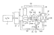
- FIG. 1 is a simplified configuration diagram showing a lean fuel intake gas turbine including a fluid mixer according to a first embodiment of the present invention.
- the gas turbine GT includes a compressor 1, a catalytic combustor 2 including a catalyst such as platinum or palladium, and a turbine 3.
- the rotating machine 4 serving as a generator and a starter is driven by the output of the gas turbine GT.
- the low calorie gas used in this gas turbine GT for example, air and fuel (such as VAM (Ventilation Air Methane) generated in a coal mine) and CMM (Coal Mine Methane) having a higher combustible component (methane) concentration than this
- VAM Vehicle Air Methane
- CMM Coal Mine Methane
- the working gas G1 mixed with the combustible component is compressed by the compressor 1, and the high-pressure compressed gas G2 is sent to the catalytic combustor 2.
- the compressed gas G2 is combusted by a catalytic reaction by a catalyst such as platinum or palladium in the catalytic combustor 2, and a high-temperature / high-pressure combustion gas G3 generated thereby is supplied to the turbine 3 to drive the turbine 3.
- the turbine 3 is connected to the compressor 1 via the rotary shaft 5, and the compressor 1 is driven by the turbine 3.
- the power generation device 50 including the gas turbine GT and the rotating machine 4 is constructed.
- the fuel concentration (combustible component concentration) in the working gas G1 when only VAM is used is below the combustible concentration limit even at the temperature after the temperature rise by the compression in the compressor 1, so that ignition is possible. Absent. Further, even when CMM having a high concentration of combustible components is added to the working gas G1 when only the VAM is used, the temperature after the temperature rise by compression in the compressor 1 falls below the combustible concentration limit. Thus, since the addition amount is controlled, there is no ignition.
- the gas turbine GT further includes a regenerator (heat exchanger) 6 that heats the compressed gas G2 introduced from the compressor 1 to the catalytic combustor 2 by the exhaust gas G4 from the turbine 3, and a compression that flows into the catalytic combustor 2.
- a heating burner 7 that activates the catalyst by raising the temperature of the gas G2 at the start-up is provided.
- This heating burner 7 mixes fuel with an extraction gas G20 partially extracted from the compressed gas G2 compressed by the compressor 1 and flame-combusts it, from the turbine 3 to the regenerator 6. It mixes with the exhaust gas G4 supplied to and heats it.
- the warming burner 7 is connected to a bleed valve 8 for controlling the supply amount of the extraction gas G20 to the warming burner 7.
- the exhaust gas G4 flowing out from the regenerator 6 is silenced through a silencer (not shown) and then released to the outside.
- the supply amount of the extraction gas G20 to the heating burner 7 by the extraction valve 8 is controlled by an output signal from the controller 20.
- the fuel is supplied to the warming burner 7 while adjusting the flow rate of the CMM fed from the CMM source 13 such as the excavation part of the coal mine by the first fuel flow control valve 9.
- the controller 20 adjusts the flow rate of the CMM by the first fuel flow rate control valve 9.
- the supply of the working gas G1 to the compressor 1 is performed by adjusting the flow rate of the CMM extracted from the CMM source 13 to the VAM from the VAM source 12, such as ventilation in a coal mine, as necessary by the second fuel flow control valve 10. It is done by mixing.
- CMM contains about 10-30% methane gas
- VAM contains less than 1% methane gas.
- the controller 20 also performs CMM flow rate adjustment by the second fuel flow rate control valve 10.
- an air source 19 such as outside air is connected to the suction passage from the VAM source 12 to the compressor 1 through an on-off valve 18 for purging at the time of starting operation, which will be described later.
- the rotating shaft 5 that connects the compressor 1 and the turbine 3 is a single shaft, and the rotating shaft 5 and the rotating machine 4 are connected via a speed reducer 17. Electric power obtained by the rotating machine 4 driven by the rotation of the turbine 3 is input to the controller 20.
- the power converter 11 drives the rotating machine 4 as a starter motor at the time of starting by the controller 20.
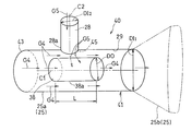
- the turbine 3 and the regenerator 6 are connected by a hollow cylindrical exhaust duct 25.
- the exhaust duct 25 is connected to a cylindrical portion 25a near the turbine 3 and a downstream end portion of the cylindrical portion 25a, and has a diameter-expanded portion that expands toward the regenerator 6, that is, toward the downstream side. 25b.
- the diameter-enlarged portion 25b has a circular cross-sectional shape at the upstream end, a vertically long rectangular shape at the downstream end, and the cross-sectional shape therebetween gradually changes from a circle to a rectangle. It is a hollow cylinder. However, the downstream end of the enlarged diameter portion 25b can also have a circular cross-sectional shape.
- the cylindrical portion 25a of the exhaust duct 25 forms a first pipe, and the first pipe 25a is supplied with a warming gas G5 from the heating burner 7 for supplying it into the exhaust duct 25.
- Two pipes 28 are connected.
- a hollow cylinder-shaped mixing accelerator 38 having an axial center C1 (FIG. 3) along the direction in which the exhaust gas G4 flows is arranged in this example.
- the heating burner 7 is supplied with CMM as a fuel component from the CMM source 13 (FIG. 1) as described above.
- An extraction gas passage 27 is branched from a compressed gas passage 24 for supplying the compressed gas G2 from the compressor 1 to the regenerator 6, and the heating burner 7 and an extraction valve located upstream thereof are provided in the extraction gas passage 27. 8 are provided.
- a downstream side of the extraction gas passage 27 with respect to the heating burner 7 is formed as a second pipe 28.
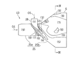
- the fluid mixer 40 includes a part of the exhaust duct 25, a mixing accelerator 38, and a downstream portion of the second pipe 28.
- the main body 41 of the fluid mixer 40 is formed by a downstream portion of a first pipe (cylindrical portion) 25a that is a part of the exhaust duct 25 and an enlarged diameter portion 25b.
- a first inlet 43 is provided at the upstream end of the main body 41, and a second inlet 45 that is continuous with the second pipe 28 is provided on the peripheral wall of the main body 41.
- the fluid mixer 40 and the regenerator (heat exchanger) 6 disposed downstream of the fluid mixer 40 constitute a heat exchange system 42.
- the exhaust gas G4 which is the first fluid flowing in the exhaust duct 25, flows into the main body 41 from the first inflow port 43 and flows both outside and inside the mixing accelerator 38.
- the mixing promoting body 38 is disposed concentrically with the cylindrical portion 25a.
- the mixing accelerator 38 has a cylindrical shape, but may be a hollow member.
- the mixing accelerator 38 may be a polygonal column, a truncated cone, or a polygonal truncated cone, and the downstream end surface of the mixing accelerator 38 has a diameter.
- the shape may be inclined with respect to the direction (FIG. 10 described later).
- the second pipe 28 is connected by welding at right angles to the cylindrical portion 25 a of the exhaust duct 25, and the heating gas G ⁇ b> 5 that is the second fluid from the second pipe 28 is downstream of the second pipe 28.
- the heating gas G5 that has collided with the outer peripheral surface 38a of the mixing accelerator 38 is guided along the outer peripheral surface 38a of the mixing accelerator 38 while being mixed with the inner peripheral surface 29 of the cylindrical portion 25a of the exhaust duct 25 and the mixing accelerator. It flows between the outer peripheral surface 38a of 38.
- the exhaust gas G4 that is the first fluid has a lower temperature than the heating gas G5 that is the second fluid.
- the mixing accelerator 38 is positioned so that the outer peripheral surface 38a faces the second inlet 45 so that the heating gas G5, which is the second fluid from the second pipe 28, collides with it.
- the entire second inflow port 45 formed by the second pipe 28 in the axial direction of the mixing accelerator 38 is the outer peripheral surface of the mixing accelerator 38 and the mixing accelerator 38 in a side view. Overlapping in the axial direction. That is, the second inflow port 45 is located between the upstream end edge 38 b and the downstream end edge 38 c of the mixing promoting body 38.
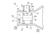
- the outer diameter DO of the mixing accelerator 38 in FIG. 3 is about 0.35 to 0.55 times, preferably 0.4 to 0.5 times, the inner diameter DI 1 of the cylindrical portion 25a.
- the thickness of the mixing accelerator 38 is preferably reduced as long as the strength is maintained.
- the outer diameter DO of the mixing accelerator 38 is about 0.9 to 1.3 times the inner diameter DI 2 of the second pipe 28, and preferably 1.0 to 1.2 times.
- the length L of the mixing accelerator 38 is about 1.2 to 3.0 times the inner diameter DI 2 of the second pipe 28, and preferably 1.5 to 2.5 times.
- the cylindrical portion 25 a of the exhaust duct 25 and the second pipe 28 are connected by a connection portion 44, and an edge 46 of the outlet portion 28 a of the second pipe 28 in the connection portion 44. Is substantially flush with the inner peripheral surface 29 of the cylindrical portion 25a of the exhaust duct 25. However, the downstream end edge 46 of the second pipe 28 may be disposed slightly outward in the radial direction from the inner peripheral surface 29 of the cylindrical portion 25a.
- the axis C2 of the second pipe 28 intersects with the axis C1 of the exhaust duct 25 and the mixing accelerator 38 at right angles, and the heating gas G5 from the second pipe 28 is
- the top of the mixing accelerator 38 collides with the vicinity thereof.
- the mixing accelerator 38 is supported by the cylindrical portion 25a of the exhaust duct 25 via a support member 48 extending in the radial direction.
- the support members 48 are provided at both ends in the direction of the axis C1 of the mixing accelerator 38 shown in FIG. 4, and the inner end of the supporting member 48 is a first fastening member 58 such as a bolt on the outer peripheral surface of the mixing accelerator 38.
- the outer end of the support member 48 is connected to the inner peripheral surface of the exhaust duct 25 by a second fastening member 59 such as a bolt.
- the upstream support member 48 is rigidly supported in the flow direction (axial direction), and the other of the support members 48, in this example, the downstream side
- the support member 48 is supported so as to be movable in the axial direction, so that the thermal expansion in the axial direction of the mixing accelerator 38 can be absorbed.
- a long hole in the axial direction is provided in the outer end portion of the support member 48 on the downstream side, and the second fastening member 59 is inserted into the long hole, so that the mixing promoting body 38 is moved in the axial direction. It is free to move.
- the support members 48 are made of a plate material and are arranged in the circumferential direction, and the inner end portion and the outer end portion in the radial direction of each support member 48 are formed in a bifurcated shape, and mixed.
- the thermal expansion in the radial direction of the promotion body 38 can be absorbed.
- the support structure of the mixing accelerator 38 is not limited to the illustrated example, and may be configured so as to be able to absorb the thermal expansion of the mixing accelerator 38, for example, between the exhaust duct 25 and the mixing accelerator 38.
- the thermal expansion of the mixing promoting body 38 can be absorbed by supporting the cantilever only by the support member 48 formed of a link mechanism.
- the regenerator 6 is warmed by ignition of the heating burner 7 to raise the temperature of the compressed gas G2 passing through the regenerator 6. Then, the temperature of the catalytic combustor 2 is increased to a predetermined temperature at which catalytic reaction is possible.
- the exhaust gas G4 from the turbine 3 and the heating gas G5 from the heating burner 7 are mixed.
- the exhaust gas G4 flows into the main body 41 of the fluid mixer 40 from the first inflow port 43, flows through the inside and outside of the mixing accelerator 38, and the heating gas G5 is the second gas.
- the outer peripheral surface 38a of the mixing accelerator 38 and the inner peripheral surface of the main body 41 that is, the cylindrical portion 25a of the exhaust duct 25. It flows between the inner peripheral surface 29.
- the heating gas G5 flowing between the outer peripheral surface 38a of the mixing accelerator 38 and the inner peripheral surface 29 of the main body 41 is first mixed with the exhaust gas G4 flowing through the outside of the mixing accelerator 38 (primary mixing). Since the heating gas G5 collides with the outer peripheral surface 38a of the mixing accelerator 38, it is guided along the outer peripheral surface 38a of the mixing accelerator 38 to the entire area in the radial direction and the circumferential direction of the main body 41. Thereby, mixing with the exhaust gas G4 and the heating gas G5 is promoted. At this time, the entire surface of the mixing accelerator 38 is cooled by the low-temperature exhaust gas G4 flowing through the inside of the mixing accelerator 38.
- the mixed gas of the first-mixed exhaust gas G4 and the heating gas G5 further mixes with the exhaust gas G4 flowing through the inside of the mixing accelerator 38 downstream of the mixing accelerator 38 (secondary mixing).
- second mixing mixing in two stages, mixing of the exhaust gas G4 and the heating gas G5 is further promoted.
- the mixed gas that has passed through the mixing accelerator 38 flows into the enlarged diameter portion 25b of the main body 41 and is diffused, the mixing is further promoted.
- the mixing accelerator 38 since the mixing accelerator 38 has a shape having the axis C1 along the flow direction of the exhaust gas G4, the resistance that the exhaust gas G4 receives from the mixing accelerator 38 may be small. Therefore, the pressure loss of the exhaust gas G4 is effectively suppressed during the rated operation with the longest operation time.
- the mixing promotion body 38 having an axis C1 along the flow direction of the exhaust gas G4 is disposed inside the main body 41, and the exhaust gas G4 is in the direction of the axis C1 of the mixing promotion body 38. Accordingly, the pressure loss of the exhaust gas G4 can be suppressed. Further, since the heating gas G5 is introduced toward the outer peripheral surface 38a of the mixing promoting body 38, the heating gas G5 collides with the outer peripheral surface 38a of the mixing promoting body 38 and the radial direction and the circumferential direction of the main body 41. As a result, the exhaust gas G4 and the heating gas G5 are sufficiently mixed outside the mixing accelerator 38.
- the heating gas G5 is mixed with the exhaust gas G4 flowing outside the mixing accelerator 38 and then mixed again with the exhaust gas G4 flowing inside the mixing accelerator 38, whereby the exhaust gas G4 and the heating gas G5 Is promoted. Furthermore, since the mixing promotion body 38 is disposed inside the main body 41 and the second inflow port 45 for introducing the heating gas G5 is disposed toward the mixing promotion body 38, the structure is simple. .
- the mixing promotion body 38 is disposed substantially concentrically with the main body 41, the distance between the second inlet 45 and the mixing promotion body 38 regardless of the installation position of the second inlet 45 in the circumferential direction of the main body 41. As a result, the positional relationship between the second inlet 45 and the mixing accelerator 38 is not required to be accurate.
- the heating gas G5 collides in the direction orthogonal to the outer peripheral surface 38a of the mixing accelerator 38, so that the heating gas G5 Is guided by the outer peripheral surface 38a of the mixing promoting body 38 and goes around the entire radial direction and circumferential direction of the exhaust duct 25. As a result, the mixing of the exhaust gas G4 and the heating gas G5 is further promoted.
- the exhaust gas G4 since the exhaust gas G4 has a lower temperature than the heating gas G5, the exhaust gas G4 cools the entire surface of the mixing accelerator 38 in contact with the high-temperature heating gas G5. There is no need to provide a separate structure for prevention, and the structure is further simplified.
- the downstream part in the main body 41 is formed by the enlarged diameter part 25b whose passage area increases toward the downstream side, the mixed gas of the exhaust gas G4 and the warming gas G5 by the enlarged diameter part 25b. Is diffused and mixing is further promoted.
- the fluid mixer 40 is disposed upstream of the regenerator 6 that is a heat exchanger, the exhaust gas G4 and the heating gas G5 are sufficiently mixed by the fluid mixer 40. After that, since it is guided to the regenerator 6, the temperature distribution in the cross section orthogonal to the flow of the mixed fluid is made uniform, so that the heat exchange efficiency is improved.
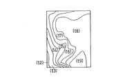
- FIG. 6 is a temperature distribution in the axial direction when the exhaust gas G4 and the heating gas G5 are mixed using the fluid mixer 40 of the above embodiment
- FIG. 7 is a sectional view taken along the line VII-VII of FIG.
- the temperature distribution in the radial direction at the outlet of the mixer 40 (inlet of the regenerator 6) is shown
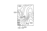
- FIGS. 8 and 9 show the temperature distribution of the comparative example.
- (1) to (21) represent regions from high temperature to low temperature. 6 and 8, the same numbers in (1) to (9) indicate the same temperature region. Similarly, in FIGS. 7 and 9, the same numbers (10) to (21) indicate the same temperature region.
- the high-temperature heating gas G5 spreads from the center portion to the lower portion of the enlarged diameter portion 25b. As a result, as shown in FIG. It can be seen that the temperature distribution is made uniform at the outlet of the mixer 40 and is mixed appropriately. On the other hand, in the fluid mixer of the comparative example, as shown in FIG. 8, the high-temperature heating gas G5 flows in a concentrated manner at the lower part of the enlarged diameter portion 25b. As a result, as shown in FIG. At the outlet of the mixer 40, the temperature distribution is uneven and not sufficiently mixed.
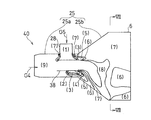
- FIG. 10 is a schematic configuration diagram showing a fluid mixer 40A according to the second embodiment.
- the difference between the fluid mixer 40A of the second embodiment and the fluid mixer 40 of the first embodiment is only that the downstream end surface 62 of the mixing accelerator 38A is an inclined surface that is inclined upward as it goes downstream.
- the structure is the same as in the first embodiment. That is, the downstream end portion of the portion (lower portion) opposite to the portion (upper portion) facing the second pipe 28 in the mixing accelerator 38 is notched and inclined.
- the inclination angle ⁇ with respect to the radial direction of the downstream end face 62 is 45 °.
- the inclination angle ⁇ can be about 20 to 60 °, and more preferably about 30 to 50 °.
- the second inflow port 45 is located between the upstream end edge 38Aa of the mixing accelerator 38A and the downstream end edge 38Ab of the portion (upper part in FIG. 10) facing the second inflow port 45 in the mixing accelerator 38A. is doing.
- the downstream portion of the cylindrical portion 25a that forms the upstream portion of the main body 41 is cylindrical, but is an expansion tube having a small taper ratio that slightly expands toward the downstream. Also good.
- the mixing promoting body 38 may be disposed inside the enlarged diameter portion 25b.
- the enlarged diameter portion 25b may be omitted, and the entire body 41 of the fluid mixer 40 may be cylindrical.
- a plurality of second inlets 45 may be provided, and different fluids may flow into the main body 41 from each inlet 45.
Abstract
Description
25 排気ダクト
28 第2の配管
29 本体の内周面
38、38A 混合促進体
38a 混合促進体の外周面
40、40A 流体混合器
41 本体(第1の配管)
42 熱交換システム
43 第1の流入口
44 接続部
45 第2の流入口
46 第2の配管の端縁
C1 軸心
G4 排ガス(第1の流体)
G5 加温用ガス(第2の流体)
Claims (7)
- 内側で第1と第2の流体を混合する中空筒状の本体と、
前記本体の上流側端部に設けられて前記第1の流体を流入させる第1の流入口と、
前記本体の内側に配置され、前記第1の流体の流れる方向に沿った軸心を有する中空筒状の混合促進体と、
前記本体の周壁に設けられて前記混合促進体の外周面に向かって前記第2の流体を流入させる第2の流入口とを備える流体混合器。 - 請求項1において、前記混合促進体が前記本体とほぼ同心に配置されている流体混合器。
- 請求項1または2において、前記本体を形成する第1の配管に、前記第2の流入口に第2の流体を供給する第2の配管が直交して接続されている流体混合器。
- 請求項1または2において、前記本体を形成する第1の配管に、前記第2の流入口に前記第2の流体を供給する第2の配管が接続され、その接続部における前記第2の配管の端縁が前記第1の配管の内周面と面一またはこれよりも径方向外方に配置されている流体混合器。
- 請求項1または2において、前記第1の流体は前記第2の流体よりも低温である流体混合器。
- 請求項1または2において、前記本体における下流部が、下流に向かって通路面積が増大する拡径部により形成されている流体混合器。
- 請求項1または2に記載の流体混合器が、熱交換器の上流側に配置されてなる熱交換システム。
Priority Applications (5)
| Application Number | Priority Date | Filing Date | Title |
|---|---|---|---|
| AU2012321964A AU2012321964B2 (en) | 2011-10-11 | 2012-08-23 | Fluid mixer and heat exchange system using same |
| UAA201404938A UA107906C2 (uk) | 2011-10-11 | 2012-08-23 | Змішувач текучих середовищ і система теплообміну, яка його використовує |
| RU2014118531/02A RU2590020C2 (ru) | 2011-10-11 | 2012-08-23 | Смеситель текучих сред и использующая его система теплообмена |
| CN201280049513.0A CN103857463B (zh) | 2011-10-11 | 2012-08-23 | 流体混合器及使用其的热交换系统 |
| US14/245,158 US10092886B2 (en) | 2011-10-11 | 2014-04-04 | Fluid mixer and heat exchange system using same |
Applications Claiming Priority (2)
| Application Number | Priority Date | Filing Date | Title |
|---|---|---|---|
| JP2011223820A JP5719745B2 (ja) | 2011-10-11 | 2011-10-11 | 流体混合器とこれを用いた熱交換システム |
| JP2011-223820 | 2011-10-11 |
Related Child Applications (1)
| Application Number | Title | Priority Date | Filing Date |
|---|---|---|---|
| US14/245,158 Continuation US10092886B2 (en) | 2011-10-11 | 2014-04-04 | Fluid mixer and heat exchange system using same |
Publications (1)
| Publication Number | Publication Date |
|---|---|
| WO2013054595A1 true WO2013054595A1 (ja) | 2013-04-18 |
Family
ID=48081655
Family Applications (1)
| Application Number | Title | Priority Date | Filing Date |
|---|---|---|---|
| PCT/JP2012/071279 WO2013054595A1 (ja) | 2011-10-11 | 2012-08-23 | 流体混合器とこれを用いた熱交換システム |
Country Status (7)
| Country | Link |
|---|---|
| US (1) | US10092886B2 (ja) |
| JP (1) | JP5719745B2 (ja) |
| CN (1) | CN103857463B (ja) |
| AU (1) | AU2012321964B2 (ja) |
| RU (1) | RU2590020C2 (ja) |
| UA (1) | UA107906C2 (ja) |
| WO (1) | WO2013054595A1 (ja) |
Cited By (2)
| Publication number | Priority date | Publication date | Assignee | Title |
|---|---|---|---|---|
| WO2015052970A1 (ja) * | 2013-10-11 | 2015-04-16 | 川崎重工業株式会社 | ガス混合器 |
| CN106268385A (zh) * | 2015-06-24 | 2017-01-04 | 贵州航空发动机研究所 | 一种高温燃气掺混装置 |
Families Citing this family (14)
| Publication number | Priority date | Publication date | Assignee | Title |
|---|---|---|---|---|
| JP5719745B2 (ja) * | 2011-10-11 | 2015-05-20 | 川崎重工業株式会社 | 流体混合器とこれを用いた熱交換システム |
| US20150124552A1 (en) * | 2013-11-04 | 2015-05-07 | Yang Shi | System and method for mixing a gas and a liquid |
| EP3181866B1 (en) | 2015-12-16 | 2018-07-04 | Airbus Operations, S.L. | Gas turbine engine for an aircraft |
| RU2666423C1 (ru) * | 2017-11-30 | 2018-09-07 | Акционерное Общество "Российский Концерн По Производству Электрической И Тепловой Энергии На Атомных Станциях" (Ао "Концерн Росэнергоатом") | Устройство для смешивания и нагрева газовых сред |
| US11857933B2 (en) * | 2018-03-09 | 2024-01-02 | Produced Water Absorbents Inc. | Systems, apparatuses, and methods for mixing fluids using a conical flow member |
| US10458446B1 (en) * | 2018-11-29 | 2019-10-29 | Vortex Pipe Systems LLC | Material flow amplifier |
| US11221028B1 (en) | 2018-11-29 | 2022-01-11 | Vortex Pipe Systems LLC | Cyclonic flow-inducing pump |
| ES2713123B2 (es) * | 2019-02-19 | 2019-11-06 | Univ Madrid Politecnica | Sistema termico con compresor y turbina de expansion de gas en circuito cerrado, con aportacion de calor por fuente exterior, y recuperacion interna de calor y de energia mecanica, para generacion de electricidad y procedimiento |
| KR102086440B1 (ko) * | 2019-05-31 | 2020-03-09 | 주식회사 이엠코 | 화력발전소의 배가스 처리장치 |
| US11002301B1 (en) | 2020-09-15 | 2021-05-11 | Vortex Pipe Systems LLC | Material flow modifier and apparatus comprising same |
| CN112934014A (zh) * | 2021-01-30 | 2021-06-11 | 河南省奥瑞环保科技有限公司 | 多种气体动态配气控制装置及系统 |
| US11378110B1 (en) | 2022-01-05 | 2022-07-05 | Vortex Pipe Systems LLC | Flexible fluid flow modifying device |
| CN115790247B (zh) * | 2023-01-06 | 2023-04-21 | 中国核动力研究设计院 | 均流部件及换热装置 |
| US11739774B1 (en) | 2023-01-30 | 2023-08-29 | Vortex Pipe Systems LLC | Flow modifying device with performance enhancing vane structure |
Citations (6)
| Publication number | Priority date | Publication date | Assignee | Title |
|---|---|---|---|---|
| JPS5372273U (ja) * | 1976-11-18 | 1978-06-16 | ||
| JPS6046117U (ja) * | 1983-09-09 | 1985-04-01 | 三菱重工業株式会社 | 流体混合装置 |
| JPH0448921A (ja) * | 1990-06-18 | 1992-02-18 | Inax Corp | エゼクタ |
| JP2003126667A (ja) * | 2001-10-22 | 2003-05-07 | Mitsuru Kitahara | 空気混合供給装置 |
| JP2006326571A (ja) * | 2005-04-28 | 2006-12-07 | Hitachi Ltd | 流体混合装置 |
| JP2007500074A (ja) * | 2003-07-29 | 2007-01-11 | ジュモン ソシエテ アノニム | 2つの流体を混合する装置、及び該装置を使用して超高温流体を冷却する方法 |
Family Cites Families (29)
| Publication number | Priority date | Publication date | Assignee | Title |
|---|---|---|---|---|
| US1454196A (en) * | 1921-07-16 | 1923-05-08 | Trood Samuel | Device for producing and utilizing combustible mixture |
| US1466006A (en) * | 1922-09-14 | 1923-08-28 | Trood Samuel | Apparatus for producing and utilizing combustible mixture |
| US1672209A (en) * | 1923-09-24 | 1928-06-05 | Fairbanks Morse & Co | Priming device |
| US1678225A (en) * | 1926-10-28 | 1928-07-24 | Jerry W Kincade | Agitator for chemically purifying oil |
| US1903429A (en) * | 1929-08-08 | 1933-04-11 | Paul W Merchant | Mixing device |
| US2831754A (en) * | 1954-05-10 | 1958-04-22 | Jones & Laughlin Steel Corp | Solvent extraction process |
| US3304564A (en) * | 1965-10-04 | 1967-02-21 | Green Jack | Apparatus for cleaning a body of liquid and maintaining its level |
| SU394073A1 (ru) * | 1968-08-05 | 1973-08-22 | Смеситель | |
| DE1904014C3 (de) * | 1969-01-28 | 1974-06-20 | Noll Maschinenfabrik Gmbh, 4950 Minden | Vorrichtung zum kontinuierlichen Vereinigen von Getränkekomponenten in einstellbarem Mengenverhältnis |
| US4296779A (en) * | 1979-10-09 | 1981-10-27 | Smick Ronald H | Turbulator with ganged strips |
| SU882571A1 (ru) * | 1980-02-22 | 1981-11-23 | Предприятие П/Я Г-4696 | Газовоздушный смеситель |
| JPH0660640B2 (ja) * | 1985-09-09 | 1994-08-10 | 清之 堀井 | 管路に螺旋流体流を生成させる装置 |
| CH676628A5 (en) * | 1988-06-16 | 1991-02-15 | Ceramic Technology Foundation | Dual liquid mixing device - has low pressure chamber for low pressure fluid between venturi for high pressure fluid and discharge valve |
| CA1295585C (en) * | 1988-08-25 | 1992-02-11 | Chemonics Industries, Inc. | Apparatus for applying fire-fighting chemicals |
| SU1607916A1 (ru) * | 1989-01-09 | 1990-11-23 | Всесоюзный Теплотехнический Научно-Исследовательский Институт Им.Ф.Э.Дзержинского | Смеситель потоков текучих веществ |
| SE500071C2 (sv) * | 1992-06-25 | 1994-04-11 | Vattenfall Utveckling Ab | Anordning för blandning av två fluider, i synnerhet vätskor med olika temperatur |
| RU2056920C1 (ru) * | 1993-12-20 | 1996-03-27 | Товарищество с ограниченной ответственностью "Камен" | Инжекторный смеситель |
| US5743637A (en) * | 1995-11-09 | 1998-04-28 | Chem Financial, Inc. | Venturi mixing valve for use in mixing liquids |
| JP2002136855A (ja) | 2000-11-02 | 2002-05-14 | Mitsubishi Heavy Ind Ltd | 流体混合器 |
| US6453926B1 (en) * | 2001-04-10 | 2002-09-24 | Gary A. Baker | Method and apparatus for injecting a chemical into a fluid stream |
| US7029165B2 (en) * | 2001-10-26 | 2006-04-18 | Allen Thomas E | Automatically adjusting annular jet mixer |
| CN2629817Y (zh) * | 2003-06-19 | 2004-08-04 | 中国石化上海石油化工股份有限公司 | 一种气液混合射流器 |
| US7416404B2 (en) * | 2005-04-18 | 2008-08-26 | General Electric Company | Feed injector for gasification and related method |
| US20070144158A1 (en) * | 2005-12-22 | 2007-06-28 | Girard James W | Exhaust dispersion device |
| JP2008049306A (ja) | 2006-08-28 | 2008-03-06 | Hitachi Ltd | ガス混合装置 |
| JP2010149062A (ja) * | 2008-12-25 | 2010-07-08 | Fujifilm Corp | 流体の混合装置及び混合方法 |
| EP2621620B1 (en) * | 2010-09-28 | 2016-04-06 | Dow Global Technologies LLC | Reactive flow static mixer with cross-flow obstructions and method for mixing |
| JP5719745B2 (ja) * | 2011-10-11 | 2015-05-20 | 川崎重工業株式会社 | 流体混合器とこれを用いた熱交換システム |
| US9885318B2 (en) * | 2015-01-07 | 2018-02-06 | Jason E Green | Mixing assembly |
-
2011
- 2011-10-11 JP JP2011223820A patent/JP5719745B2/ja active Active
-
2012
- 2012-08-23 WO PCT/JP2012/071279 patent/WO2013054595A1/ja active Application Filing
- 2012-08-23 AU AU2012321964A patent/AU2012321964B2/en not_active Ceased
- 2012-08-23 RU RU2014118531/02A patent/RU2590020C2/ru not_active IP Right Cessation
- 2012-08-23 CN CN201280049513.0A patent/CN103857463B/zh not_active Expired - Fee Related
- 2012-08-23 UA UAA201404938A patent/UA107906C2/uk unknown
-
2014
- 2014-04-04 US US14/245,158 patent/US10092886B2/en active Active
Patent Citations (6)
| Publication number | Priority date | Publication date | Assignee | Title |
|---|---|---|---|---|
| JPS5372273U (ja) * | 1976-11-18 | 1978-06-16 | ||
| JPS6046117U (ja) * | 1983-09-09 | 1985-04-01 | 三菱重工業株式会社 | 流体混合装置 |
| JPH0448921A (ja) * | 1990-06-18 | 1992-02-18 | Inax Corp | エゼクタ |
| JP2003126667A (ja) * | 2001-10-22 | 2003-05-07 | Mitsuru Kitahara | 空気混合供給装置 |
| JP2007500074A (ja) * | 2003-07-29 | 2007-01-11 | ジュモン ソシエテ アノニム | 2つの流体を混合する装置、及び該装置を使用して超高温流体を冷却する方法 |
| JP2006326571A (ja) * | 2005-04-28 | 2006-12-07 | Hitachi Ltd | 流体混合装置 |
Cited By (3)
| Publication number | Priority date | Publication date | Assignee | Title |
|---|---|---|---|---|
| WO2015052970A1 (ja) * | 2013-10-11 | 2015-04-16 | 川崎重工業株式会社 | ガス混合器 |
| JP2015073971A (ja) * | 2013-10-11 | 2015-04-20 | 川崎重工業株式会社 | ガス混合器 |
| CN106268385A (zh) * | 2015-06-24 | 2017-01-04 | 贵州航空发动机研究所 | 一种高温燃气掺混装置 |
Also Published As
| Publication number | Publication date |
|---|---|
| US10092886B2 (en) | 2018-10-09 |
| RU2014118531A (ru) | 2015-11-20 |
| US20140219048A1 (en) | 2014-08-07 |
| JP2013081905A (ja) | 2013-05-09 |
| CN103857463B (zh) | 2016-01-27 |
| AU2012321964B2 (en) | 2015-07-30 |
| RU2590020C2 (ru) | 2016-07-10 |
| CN103857463A (zh) | 2014-06-11 |
| AU2012321964A1 (en) | 2014-05-01 |
| JP5719745B2 (ja) | 2015-05-20 |
| UA107906C2 (uk) | 2015-02-25 |
Similar Documents
| Publication | Publication Date | Title |
|---|---|---|
| JP5719745B2 (ja) | 流体混合器とこれを用いた熱交換システム | |
| JP6506503B2 (ja) | 燃焼器に燃料を供給するためのシステム | |
| JP6266290B2 (ja) | ガス・タービン・エンジンの燃焼器用燃料ノズル | |
| RU2627759C2 (ru) | Последовательное сгорание со смесителем разбавляющего газа | |
| EP2463499A1 (en) | Submerged combustion vaporizer with low NOx | |
| EP2236935A2 (en) | Method And System For Reducing The Level Of Emissions Generated By A System | |
| CN102472493B (zh) | 燃气轮机燃烧器及燃气轮机 | |
| JP6172523B2 (ja) | アキシャルピストンエンジンならびにアキシャルピストンエンジンの作動方法 | |
| JP2016194405A (ja) | タービンシステム用のマイクロミキサシステム及びその関連する方法 | |
| CN101713541A (zh) | 预混合直接喷射喷嘴 | |
| EP2559948A1 (en) | Gas turbine control device | |
| JP2013228195A (ja) | 燃焼器に動作流体を供給するためのシステムおよび方法 | |
| WO2015053004A1 (ja) | ガスタービンの燃料噴射装置 | |
| JP2016017740A (ja) | ミキサを備えた2段燃焼器配列 | |
| JP4961415B2 (ja) | ガスタービン燃焼器 | |
| US20160175786A1 (en) | Gas mixer | |
| JP2013139994A (ja) | 燃焼器および該燃焼器内に燃料を分配するための方法 | |
| WO2013099582A1 (ja) | ガスタービンにおける触媒燃焼器 | |
| JP4854613B2 (ja) | 燃焼装置及びガスタービン燃焼器 | |
| JP2007218487A (ja) | ガスタービン燃焼器 | |
| BR112020022559A2 (pt) | sistema e método de aprimorar estabilidade de combustão em uma turbina a gás | |
| JP2009150389A (ja) | ガスタービンの燃焼器における燃料供給システムの制御されたパージ方法 | |
| CN102057221B (zh) | 气体火焰稳定方法及设备 | |
| JP2014202475A (ja) | 触媒燃焼空気加熱システム | |
| US20230296252A1 (en) | Combustor nozzle, combustor, and gas turbine including the same |
Legal Events
| Date | Code | Title | Description |
|---|---|---|---|
| 121 | Ep: the epo has been informed by wipo that ep was designated in this application |
Ref document number: 12839392 Country of ref document: EP Kind code of ref document: A1 |
|
| NENP | Non-entry into the national phase |
Ref country code: DE |
|
| ENP | Entry into the national phase |
Ref document number: 2012321964 Country of ref document: AU Date of ref document: 20120823 Kind code of ref document: A |
|
| ENP | Entry into the national phase |
Ref document number: 2014118531 Country of ref document: RU Kind code of ref document: A |
|
| 122 | Ep: pct application non-entry in european phase |
Ref document number: 12839392 Country of ref document: EP Kind code of ref document: A1 |