WO2013051678A1 - 黒鉛材料、その製造方法、電池電極用炭素材料、及び電池 - Google Patents
黒鉛材料、その製造方法、電池電極用炭素材料、及び電池 Download PDFInfo
- Publication number
- WO2013051678A1 WO2013051678A1 PCT/JP2012/075891 JP2012075891W WO2013051678A1 WO 2013051678 A1 WO2013051678 A1 WO 2013051678A1 JP 2012075891 W JP2012075891 W JP 2012075891W WO 2013051678 A1 WO2013051678 A1 WO 2013051678A1
- Authority
- WO
- WIPO (PCT)
- Prior art keywords
- graphite
- graphite material
- carbon
- powder
- battery
- Prior art date
- Legal status (The legal status is an assumption and is not a legal conclusion. Google has not performed a legal analysis and makes no representation as to the accuracy of the status listed.)
- Ceased
Links
Images
Classifications
-
- C—CHEMISTRY; METALLURGY
- C01—INORGANIC CHEMISTRY
- C01B—NON-METALLIC ELEMENTS; COMPOUNDS THEREOF; METALLOIDS OR COMPOUNDS THEREOF NOT COVERED BY SUBCLASS C01C
- C01B32/00—Carbon; Compounds thereof
- C01B32/20—Graphite
- C01B32/205—Preparation
-
- H—ELECTRICITY
- H01—ELECTRIC ELEMENTS
- H01M—PROCESSES OR MEANS, e.g. BATTERIES, FOR THE DIRECT CONVERSION OF CHEMICAL ENERGY INTO ELECTRICAL ENERGY
- H01M4/00—Electrodes
- H01M4/02—Electrodes composed of, or comprising, active material
- H01M4/13—Electrodes for accumulators with non-aqueous electrolyte, e.g. for lithium-accumulators; Processes of manufacture thereof
- H01M4/133—Electrodes based on carbonaceous material, e.g. graphite-intercalation compounds or CFx
-
- C—CHEMISTRY; METALLURGY
- C01—INORGANIC CHEMISTRY
- C01B—NON-METALLIC ELEMENTS; COMPOUNDS THEREOF; METALLOIDS OR COMPOUNDS THEREOF NOT COVERED BY SUBCLASS C01C
- C01B32/00—Carbon; Compounds thereof
- C01B32/20—Graphite
-
- H—ELECTRICITY
- H01—ELECTRIC ELEMENTS
- H01M—PROCESSES OR MEANS, e.g. BATTERIES, FOR THE DIRECT CONVERSION OF CHEMICAL ENERGY INTO ELECTRICAL ENERGY
- H01M10/00—Secondary cells; Manufacture thereof
- H01M10/05—Accumulators with non-aqueous electrolyte
- H01M10/052—Li-accumulators
- H01M10/0525—Rocking-chair batteries, i.e. batteries with lithium insertion or intercalation in both electrodes; Lithium-ion batteries
-
- H—ELECTRICITY
- H01—ELECTRIC ELEMENTS
- H01M—PROCESSES OR MEANS, e.g. BATTERIES, FOR THE DIRECT CONVERSION OF CHEMICAL ENERGY INTO ELECTRICAL ENERGY
- H01M4/00—Electrodes
- H01M4/02—Electrodes composed of, or comprising, active material
- H01M4/36—Selection of substances as active materials, active masses, active liquids
- H01M4/58—Selection of substances as active materials, active masses, active liquids of inorganic compounds other than oxides or hydroxides, e.g. sulfides, selenides, tellurides, halogenides or LiCoFy; of polyanionic structures, e.g. phosphates, silicates or borates
- H01M4/583—Carbonaceous material, e.g. graphite-intercalation compounds or CFx
- H01M4/587—Carbonaceous material, e.g. graphite-intercalation compounds or CFx for inserting or intercalating light metals
-
- C—CHEMISTRY; METALLURGY
- C01—INORGANIC CHEMISTRY
- C01P—INDEXING SCHEME RELATING TO STRUCTURAL AND PHYSICAL ASPECTS OF SOLID INORGANIC COMPOUNDS
- C01P2002/00—Crystal-structural characteristics
- C01P2002/70—Crystal-structural characteristics defined by measured X-ray, neutron or electron diffraction data
-
- C—CHEMISTRY; METALLURGY
- C01—INORGANIC CHEMISTRY
- C01P—INDEXING SCHEME RELATING TO STRUCTURAL AND PHYSICAL ASPECTS OF SOLID INORGANIC COMPOUNDS
- C01P2004/00—Particle morphology
- C01P2004/60—Particles characterised by their size
- C01P2004/61—Micrometer sized, i.e. from 1-100 micrometer
-
- C—CHEMISTRY; METALLURGY
- C01—INORGANIC CHEMISTRY
- C01P—INDEXING SCHEME RELATING TO STRUCTURAL AND PHYSICAL ASPECTS OF SOLID INORGANIC COMPOUNDS
- C01P2006/00—Physical properties of inorganic compounds
- C01P2006/12—Surface area
-
- H—ELECTRICITY
- H01—ELECTRIC ELEMENTS
- H01M—PROCESSES OR MEANS, e.g. BATTERIES, FOR THE DIRECT CONVERSION OF CHEMICAL ENERGY INTO ELECTRICAL ENERGY
- H01M4/00—Electrodes
- H01M4/02—Electrodes composed of, or comprising, active material
- H01M2004/021—Physical characteristics, e.g. porosity, surface area
-
- Y—GENERAL TAGGING OF NEW TECHNOLOGICAL DEVELOPMENTS; GENERAL TAGGING OF CROSS-SECTIONAL TECHNOLOGIES SPANNING OVER SEVERAL SECTIONS OF THE IPC; TECHNICAL SUBJECTS COVERED BY FORMER USPC CROSS-REFERENCE ART COLLECTIONS [XRACs] AND DIGESTS
- Y02—TECHNOLOGIES OR APPLICATIONS FOR MITIGATION OR ADAPTATION AGAINST CLIMATE CHANGE
- Y02E—REDUCTION OF GREENHOUSE GAS [GHG] EMISSIONS, RELATED TO ENERGY GENERATION, TRANSMISSION OR DISTRIBUTION
- Y02E60/00—Enabling technologies; Technologies with a potential or indirect contribution to GHG emissions mitigation
- Y02E60/10—Energy storage using batteries
-
- Y—GENERAL TAGGING OF NEW TECHNOLOGICAL DEVELOPMENTS; GENERAL TAGGING OF CROSS-SECTIONAL TECHNOLOGIES SPANNING OVER SEVERAL SECTIONS OF THE IPC; TECHNICAL SUBJECTS COVERED BY FORMER USPC CROSS-REFERENCE ART COLLECTIONS [XRACs] AND DIGESTS
- Y10—TECHNICAL SUBJECTS COVERED BY FORMER USPC
- Y10T—TECHNICAL SUBJECTS COVERED BY FORMER US CLASSIFICATION
- Y10T428/00—Stock material or miscellaneous articles
- Y10T428/29—Coated or structually defined flake, particle, cell, strand, strand portion, rod, filament, macroscopic fiber or mass thereof
- Y10T428/2982—Particulate matter [e.g., sphere, flake, etc.]
Definitions
- the present invention relates to a graphite material, a carbon material for battery electrodes, and a battery. More specifically, the present invention relates to a graphite material suitable as an electrode material for a non-aqueous electrolyte secondary battery and a manufacturing method thereof, a carbon material for battery electrodes, and a secondary battery excellent in charge / discharge cycle characteristics and large current load characteristics.
- Lithium ion secondary batteries are mainly used as power sources for portable devices. Mobile devices and the like have diversified functions and have increased power consumption. Therefore, the lithium ion secondary battery is required to increase its battery capacity and simultaneously improve the charge / discharge cycle characteristics. Furthermore, there is an increasing demand for high-power and large-capacity secondary batteries such as electric tools such as electric drills and hybrid vehicles. Conventionally, lead secondary batteries, nickel cadmium secondary batteries, and nickel metal hydride secondary batteries have been mainly used in this field, but expectations are high for small, lightweight, high energy density lithium ion secondary batteries. There is a need for a lithium ion secondary battery that is excellent in large current load characteristics.
- the main required characteristics are long-term cycle characteristics over 10 years and large current load characteristics for driving high-power motors.
- a high volumetric energy density is required to extend the cruising range, which is harsh compared to mobile applications.
- a lithium salt such as lithium cobaltate is generally used for the positive electrode active material
- a carbonaceous material such as graphite is used for the negative electrode active material.
- Graphite includes natural graphite and artificial graphite. Of these, natural graphite is available at low cost. However, since natural graphite has a scaly shape, when it is made into a paste together with a binder and applied to a current collector, the natural graphite is oriented in one direction. When charging with such an electrode, the electrode expands in only one direction, and the performance as an electrode is reduced. Although natural graphite granulated has been proposed, spherical natural graphite is crushed and oriented by pressing during electrode production. Moreover, since the surface of natural graphite was active, a large amount of gas was generated during the initial charge, the initial efficiency was low, and the cycle characteristics were not good. In order to solve these problems, Japanese Patent No. 3534391 (US Pat. No. 6,632,569; Patent Document 1) and the like propose a method of coating artificial carbon on the surface of natural graphite processed into a spherical shape.
- Artificial graphite typified by graphitized products such as petroleum, coal pitch, and coke can also be obtained at a relatively low cost.
- artificial graphite made from non-needle-shaped coke can be made relatively high in volume energy density by heat treatment at high temperatures, and satisfies the cycle characteristics and high rate characteristics that are strongly required for large batteries. It is possible to obtain a negative electrode material. These materials do not have very high crystallinity like natural graphite, but they are not as crystallized as hard carbon and amorphous carbon materials, and they can exhibit high performance due to balanced crystal disturbances. It is thought that it became.
- JP-A-7-320740 (US Pat. No. 5,587,255)
- the material manufactured by the method described in Patent Document 1 can cope with the high capacity, low current, and medium cycle characteristics required for mobile applications and the like, but the large current and super long cycle of the large battery as described above. It is very difficult to meet requirements such as characteristics.
- the negative electrode material described in Patent Document 2 has a volume energy density that is too low and is very expensive, and is therefore used only for some special large batteries.
- An object of the present invention is to provide a negative electrode carbon material for a lithium ion secondary battery capable of producing an electrode ensuring high initial efficiency while maintaining ultra-long cycle characteristics, large current load characteristics, and high energy density required by a large battery. It is to provide a graphite material suitable for the above.
- the present invention relates to the following graphite materials, carbon materials for battery electrodes, electrode pastes, batteries and lithium ion secondary batteries, and methods for producing graphite materials.
- the oxygen amount a (mass%) between the particle surface and the depth direction up to 40 nm is 0.010.
- ⁇ a ⁇ 0.04 Graphite material [2]
- the average interplanar spacing (d 002 ) of the crystallites calculated by the Gakushin method using the powder X-ray diffraction method is 0.3356 to 0.3375 nm and the thickness of the crystal in the C-axis direction (Lc 2.
- Graphite material Any of the above 1 to 4, wherein the loose bulk density is 0.7 g / cm 3 or more and the powder density when tapping 400 times is 0.8 to 1.6 g / cm 3 or less.
- a carbon material for battery electrodes comprising the graphite material as described in any one of 1 to 5 above.
- An electrode paste comprising the battery electrode carbon material as described in 6 above and a binder.
- a battery including the molded article of the electrode paste as described in 7 above as a constituent element.
- a lithium ion secondary battery including the molded article of the electrode paste as described in 7 above as a constituent element.
- a method for producing a graphite material which is heat-treated in an Atchison furnace in which the pulverized material 1 is embedded, and the thickness of the packing powder present around the pulverized material 1 is 20 cm or more.
- a step of graphitizing at a temperature, and the carbonization or graphite particles having a volume-based average particle diameter (D50) measured by a laser diffraction method of 2 to 500 ⁇ m are placed in a graphite crucible as a filling powder.
- the carbon raw material is a crude oil distillation residue having a total composition of asphaltene and resin of 30 to 80% by mass and sulfur content of 0.3 to 6% by mass, and the furnace heater outlet temperature before the coke drum is set to 550 15.
- a battery electrode with high initial efficiency can be obtained while maintaining high capacity, high energy density, and high cycle characteristics. Can do.
- the above graphite material is excellent in economy and mass productivity, and can be produced by a method with improved safety.
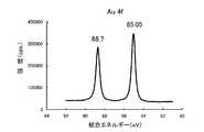
- the Au 4f narrow spectrum of the Au standard sample before performing energy calibration which is used for measuring the amount of surface oxygen in the examples.
- the graphite material according to a preferred embodiment of the present invention has a peak intensity of O 1s obtained by HAX-PES measurement using a hard X-ray of 7940 eV with respect to the depth direction from the particle surface.
- the amount of oxygen a (mass%) up to 40 nm is 0.010 ⁇ a ⁇ 0.04.
- the measurement of the surface oxygen concentration of a material has been performed by XPS.
- only an oxygen concentration of up to about 1 to 2 nm can be measured from the material surface, and measurement of a deeper portion is very difficult.
- the SEI film can be stably formed when the surface structure contains a predetermined amount of oxygen. If the amount of oxygen is too large, side reactions during the generation of the SEI film increase. It is considered that the initial efficiency is lowered. On the other hand, if the amount of oxygen is too low as in natural graphite, the fresh and highly active graphite edge portion is exposed on the surface, so that the reactivity is increased and the initial efficiency is decreased.
- the upper limit of the preferable oxygen amount a is 0.040% by mass, more preferably 0.030% by mass. It is considered that the surface oxygen concentration of artificial graphite depends on the processing conditions in the graphitization process which is the final process of production. The specific measurement method of the oxygen amount a is as described in the column of the examples.
- the graphite material in the preferred embodiment of the crystalline present invention preferably has an average spacing d 002 of (002) plane by X-ray diffraction method is .3356 ⁇ 0.3375 nm, more preferably 0. 3356 to 0.3360 nm.
- the thickness (Lc) of the crystal in the C-axis direction is preferably 30 to 1000 nm, more preferably 50 to 200 nm, and still more preferably 80 to 100 nm.
- d 002 and Lc can be measured by a known method using a powder X-ray diffraction (XRD) method (Inadayoshi Noda, Michio Inagaki, Japan Society for the Promotion of Science, 117th Committee Material, 117-71-A- 1 (1963), Michio Inagaki et al., Japan Society for the Promotion of Science, 117th Committee Materials, 117-121-C-5 (1972), Michio Inagaki, “Carbon”, 1963, No. 36, pages 25-34) .
- XRD powder X-ray diffraction
- Mean spacing d 002 is high crystallinity overall graphitized by in .3356 ⁇ 0.3375 nm, Lc is the crystallite size in the thickness direction is increased by the above range, both the lithium ion inter It is shown that more space can be culled.
- the graphite material according to a preferred embodiment of the present invention has an average aspect ratio of primary particles of maximum length Dmax / maximum length vertical length DNmax (Dmax: maximum length at two points on the contour of the particle image).
- Dmax maximum length at two points on the contour of the particle image.
- DNmax the shortest length connecting two straight lines vertically when an image is sandwiched between two straight lines parallel to the maximum length), preferably 1 to 4, more preferably 1 to 2, more preferably 1.00 to 1.32 is more preferable, and 1.00 to 1.20 is most preferable.
- the graphite material in a preferred embodiment of the present invention preferably has an average particle size (D50) of 3 to 20 ⁇ m in a volume-based particle size distribution measured by a laser diffraction method. Further preferred D50 is 5 to 18 ⁇ m.
- a laser diffraction type particle size distribution measuring device for example, a Malvern Mastersizer can be used.
- the graphite material in a preferred embodiment of the present invention does not substantially contain particles having a particle size of 0.5 ⁇ m or less. Particles of 0.5 ⁇ m or less have a large active point on the surface and reduce the initial efficiency of the battery.
- substantially not contained means that particles having a particle size of 0.5 ⁇ m or less are 0.1% by mass or less.
- the content of particles of 0.5 ⁇ m or less can be measured by a laser diffraction particle size distribution measuring apparatus as described above. Further, the particle size of the filling powder was also measured by the same method as described above.
- the graphite material in a preferred embodiment of the present invention preferably has a BET specific surface area of 0.5 to 4 m 2 / g, more preferably 0.6 to 2 m 2 / g, and 0.8 to 1.8 m 2 / g is more preferable. If the specific surface area is too high, the surface activity of the graphite powder increases, and the initial efficiency tends to decrease due to decomposition of the electrolytic solution and the like. Furthermore, a large amount of binder is required when forming the electrode, and the coverage of graphite particles by the binder is increased, so that the discharge capacity of the battery tends to decrease, which is not preferable.
- the graphite material in a preferred embodiment of the present invention has a loose bulk density (0 times tapping) of 0.7 g / cm 3 or more and a powder density (tap density) when tapped 400 times. Is preferably 0.8 to 1.6 g / cm 3 . More preferably, it is 0.9 to 1.6 g / cm 3 , and most preferably 1.1 to 1.6 g / cm 3 .
- the loose bulk density is a density obtained by dropping 100 g of a sample from a height of 20 cm onto a measuring cylinder and measuring the volume and mass without applying vibration.
- the tap density is a density obtained by measuring the volume and mass of 100 g of powder tapped 400 times using a cantachrome auto tap.
- the graphite material in a preferred embodiment of the present invention can be produced by subjecting a carbon raw material to heat treatment at 2000 to 3300 ° C.
- the carbon raw material is preferably selected from, for example, petroleum pitch, coal pitch, coal coke, petroleum coke, and mixtures thereof, and the maximum heat history is preferably 500 to 1800 ° C.
- petroleum coke is preferable, and a residue obtained by distilling crude oil into an oil refining process at atmospheric pressure or reduced pressure, or a product obtained by coking a pyrolysis tar or the like can be used.
- the carbon raw material preferably has a weight loss of heating (for example, a volatile content of hydrocarbon accompanying carbonization) of 5 to 20% by mass when heated from 300 ° C. to 1200 ° C. in an inert atmosphere. If the weight loss by heating is less than 5% by mass, the particle shape after pulverization tends to be plate-like. Further, the pulverized surface (edge portion) is exposed, the specific surface area is increased, and side reactions are increased. Conversely, if it exceeds 20% by mass, the particles after graphitization will increase the binding between the particles, which will affect the yield.
- a weight loss of heating for example, a volatile content of hydrocarbon accompanying carbonization
- the carbon raw material is pulverized before graphitization.
- a known jet mill, hammer mill, roller mill, pin mill, vibration mill or the like is used for pulverization.
- the pulverization is preferably performed with a heat history as low as possible. The lower the heat history, the lower the hardness and the easier the pulverization, and the random crack direction at the time of crushing tends to make the aspect ratio small. In addition, the probability that the edge portion exposed to the pulverized surface is repaired in the subsequent heating process is increased, and there is an effect that side reactions during charging and discharging can be reduced.
- the pulverized carbon raw material is preferably classified so that the volume-based average particle diameter (D50) measured by a laser diffraction method is 3 to 20 ⁇ m.
- D50 can be measured by a laser diffraction particle size distribution measuring device such as Malvern Mastersizer.
- the average aspect ratio of the pulverized carbon raw material is preferably 1 to 4, more preferably 1 to 2, still more preferably 1.00 to 1.32, and most preferably 1.00 to 1.20.
- the aspect ratio can be measured by the method described in the examples.
- the pulverized carbon raw material can be fired at a low temperature of about 500 to 1800 ° C. in a non-oxidizing atmosphere before graphitization.
- a preferred temperature is 800-1500 ° C.
- gas generation in the next graphitization treatment can be reduced, and since the bulk density can be lowered, the graphitization treatment cost can also be reduced.
- preheating at 800 to 1500 ° C. can be performed before pulverization.
- Graphitization treatment As the graphitization treatment, an Acheson furnace or a furnace using a graphite heater can be used. Industrial graphitization in artificial graphite production is often performed in an Atchison furnace used for the production of artificial graphite electrodes.
- the Atchison furnace stuffs coke grains called packing powder in a rectangular parallelepiped container, embeds the object to be heated, energizes the packing powder, and indirectly heats the object to be heated with Joule heat generated therefrom.
- a graphitization treatment is performed at a temperature of about 3000 ° C. In this case, the heated packing powder is first attacked by oxygen, so that the heated object inside is protected to some extent from the attack of oxygen in the atmosphere.
- the size of the coke grains of this stuffing powder is usually on the order of several mm to several cm. Under this normal condition, the attack of oxygen reaches the object to be heated, so the oxygen amount a (mass%) between the surface and the depth direction up to 40 nm is controlled to 0.010 ⁇ a ⁇ 0.04. It was very difficult to do.
- the filling powder is refined to prevent oxygen from entering.
- the average particle size of the packing powder is such that the volume-based average particle size (D50) by laser diffraction method is 500 ⁇ m or less, preferably 100 ⁇ m or less, more preferably 50 ⁇ m or less, and most preferably 30 ⁇ m or less.
- D50 is preferably 2 ⁇ m or more.
- D50 is 1 ⁇ m or less, it is difficult for the gas generated during heating to escape and explosion may occur.
- the aspect ratio of the packing powder particles is preferably 5 or less, more preferably 4 or less, and still more preferably 3 or less. By setting the aspect ratio to 5 or less, the fluidity of the filling powder at the time of gas generation becomes high, rapid gas generation can be suppressed, and fine gas can be frequently generated.
- the aspect ratio is preferably 1.2 or more. If the aspect ratio is less than 1.2, the fluidity of the stuffed powder particles becomes too intense, and powder may be ejected during heating.
- the thickness for embedding the object to be heated in the filling powder is preferably 20 cm or more, more preferably 25 cm or more, and most preferably 30 cm or more. There is no problem even if it is made thicker, but if it is too thick, the amount of powder that can be heat-treated is reduced with respect to the size of the furnace body, and the production efficiency is lowered.
- the thickness includes not only the distance from the upper surface of the packing powder of the Atchison furnace to the upper end of the object to be heated, but also the distance from the side wall and bottom surface of the Atchison furnace to the object to be heated.
- the wall material of the Atchison furnace has some air permeability (no sealing function), so it can also transmit oxygen.
- the stuffing powder are not particularly limited as long as there is conductivity sufficient to allow energization as an Atchison furnace.
- the object to be heated is packed in a container that can be covered.
- the container that can be used in a preferred embodiment of the present invention is not particularly limited as long as it is made of a material that can withstand a heat treatment of about 3000 ° C. and does not cause a significant reaction with an object to be heated.
- the object to be heated can be heat-treated without using a container. In this case, it is possible to obtain a graphitized object to be heated by confirming an area such as a depth in which the object to be heated is buried and collecting the powder in the area after the graphitization is completed.
- the conditions are met, it is possible to obtain graphitized particles having a target surface oxygen concentration by filling the entire furnace with the object to be heated and collecting the powder in the area after electrification and graphitization.
- the article to be heated also serves as a filling powder.
- Adjustment of the amount of oxygen when performed with a graphite heater can be performed using, for example, a double graphite crucible. That is, the object to be heated is packed in the graphite crucible A, the graphite crucible A is put into the graphite crucible B larger than the graphite crucible A, and the space formed between the graphite crucible A and the graphite crucible B is filled in the above-mentioned Atchison furnace.
- This is a method in which the same packing powder as that used is packed, covered, and placed in a graphite heater furnace and heated in an argon atmosphere. As in the above case, the attack by oxygen is reduced by stuffing.
- the distance of the gap between the graphite crucible A and the graphite crucible B (that is, the thickness containing the filling powder) is important. If the distance is short, the surface oxygen concentration of the heated object is less than the upper limit of the specified range of 0.04% by mass. If the distance is too high and the distance is too large, the lower limit is less than 0.01% by mass, so adjustment is necessary. Although the distance depends on the size of the graphite heater, the size of the packing powder, the amount of oxygen in the gas, and other conditions, it cannot be generally stated, but it is usually about 1 to 20 cm.
- the lower limit of the graphitization temperature is usually 2000 ° C, preferably 2500 ° C, more preferably 2900 ° C, and most preferably 3000 ° C.
- the upper limit of the graphitization temperature is not particularly limited, but is preferably 3300 ° C. from the viewpoint that a high discharge capacity is easily obtained. It is preferable not to crush or grind the graphite material after the graphitization treatment. When pulverizing or pulverizing after the graphite treatment, the smooth surface may be damaged and the performance may be deteriorated.
- the graphite material in a preferred embodiment of the present invention can be used after being coated with another carbon material.
- the graphite particles constituting the graphite material can be coated with optical isotropic carbon on the surface.
- the coating can improve the input characteristics during charging and improve the characteristics required for large batteries.
- the coating amount is not particularly limited, but is preferably from 0.1 to 10% by weight based on the core material.
- a known technique can be used for the coating method and is not particularly limited.
- a coal tar pitch with a diameter of 0.1 to 1 ⁇ m and a graphite material are coated with graphite particles by a mechanochemical method using a mechano-fusion made by Hosokawa Micron, and heated at 800 to 3300 ° C. in a non-oxidizing atmosphere.
- a method of forming optically isotropic carbon on the surface, or a composition containing a polymer is adhered to at least a part of the surface of graphite particles, and heat-treated at 800 to 3300 ° C. in a non-oxidizing atmosphere. Examples thereof include a method of forming isotropic carbon.
- composition containing the polymer for example, a composition containing a drying oil or a fatty acid thereof and a phenol resin can be used.
- the latter method is described in, for example, Japanese Patent Application Laid-Open No. 2003-1000029 (Pamphlet of International Publication No. 03/028128) and Japanese Patent Application Laid-Open No. 2005-019397 (Pamphlet of International Publication No. 2004/109825).
- a part of carbon fiber can also be made to adhere to the said particle
- the carbon fibers in the electrode can be easily dispersed, and the cycle characteristics and the current load characteristics are further enhanced by a synergistic effect with the characteristics of the graphite particles as the core material.
- the adhesion amount of the carbon fiber is not particularly limited, but is preferably 0.1 to 5% by mass with respect to the graphite material as the core material.
- a known method can be used as the bonding method, and is not particularly limited.
- carbon fiber is bonded simultaneously with a graphite particle coating by mechanochemical method using a coal tar pitch with a diameter of 0.1 to 1 ⁇ m, graphite material and carbon fiber using a mechano-fusion made by Hosokawa Micron, and 800 in a non-oxidizing atmosphere.
- mechanochemical method using a coal tar pitch with a diameter of 0.1 to 1 ⁇ m
- graphite material and carbon fiber using a mechano-fusion made by Hosokawa Micron, and 800 in a non-oxidizing atmosphere.
- This can be done by heating at ⁇ 3300 ° C.
- a composition containing a polymer is attached to at least a part of the surface of the graphite particles, and fibrous carbon is mixed therewith, and then the fibrous carbon is attached to the graphite particles through the composition containing the polymer,
- the graphite particles can be heat treated at 800 to 3300 ° C. in a non-oxidizing atmosphere.
- composition containing the polymer for example, a composition containing a drying oil or a fatty acid thereof and a phenol resin can be used.
- the latter method is described in, for example, Japanese Patent Application Laid-Open No. 2003-1000029 (Pamphlet of International Publication No. 03/028128) and Japanese Patent Application Laid-Open No. 2005-019397 (Pamphlet of International Publication No. 2004/109825).
- the carbon fiber examples include organic carbon fibers such as PAN-based carbon fibers, pitch-based carbon fibers, and rayon-based carbon fibers, and vapor grown carbon fibers.
- organic carbon fibers such as PAN-based carbon fibers, pitch-based carbon fibers, and rayon-based carbon fibers
- vapor grown carbon fiber having high crystallinity and high thermal conductivity is particularly preferable.
- carbon fibers are bonded to the surface of graphite particles
- vapor grown carbon fibers are particularly preferable.
- Vapor grown carbon fiber is produced, for example, by using an organic compound as a raw material, introducing an organic transition metal compound as a catalyst into a high-temperature reactor together with a carrier gas, and subsequently heat-treating (Japanese Patent Laid-Open No. Sho 60- No. 54998 (US Pat. No. 4,572,813), Japanese Patent No.
- the fiber diameter is 2 to 1000 nm, preferably 10 to 500 nm, and the aspect ratio is preferably 10 to 15000.
- the organic compound used as a raw material for carbon fiber include gases such as toluene, benzene, naphthalene, ethylene, acetylene, ethane, natural gas, carbon monoxide, and mixtures thereof. Of these, aromatic hydrocarbons such as toluene and benzene are preferred.
- the organic transition metal compound contains a transition metal serving as a catalyst. Examples of the transition metal include metals of groups IVa, Va, VIa, VIIa, and VIII of the periodic table. As the organic transition metal compound, compounds such as ferrocene and nickelocene are preferable.
- the carbon fiber may be one obtained by pulverizing or pulverizing long fibers obtained by a vapor phase method or the like. Further, the carbon fibers may be aggregated in a flock shape.
- the carbon fiber preferably has no thermal decomposition product derived from an organic compound or the like on its surface, or has a high carbon structure crystallinity.
- Carbon fibers to which no pyrolyzate is attached or carbon fibers having a high carbon structure crystallinity are obtained by, for example, firing (heat treatment) carbon fibers, preferably vapor grown carbon fibers, in an inert gas atmosphere. It is done.
- carbon fibers to which no pyrolyzate is attached can be obtained by heat treatment at about 800 to 1500 ° C. in an inert gas such as argon.
- the carbon fiber having high carbon structure crystallinity is preferably obtained by heat treatment in an inert gas such as argon at 2000 ° C. or higher, more preferably 2000 to 3000 ° C.
- the carbon fiber preferably contains a branched fiber. Further, there may be a portion where the entire fiber has a hollow structure communicating with each other. Therefore, the carbon layer which comprises the cylindrical part of a fiber is continuing.
- a hollow structure is a structure in which a carbon layer is wound in a cylindrical shape, and includes a structure that is not a complete cylinder, a structure that has a partial cut portion, and a structure in which two stacked carbon layers are bonded to one layer. .
- the cross section of the cylinder is not limited to a perfect circle, but includes an ellipse or a polygon.
- the carbon fiber has an (002) plane average plane distance d 002 of preferably 0.344 nm or less, more preferably 0.339 nm or less, and particularly preferably 0.338 nm or less, as determined by X-ray diffraction.
- a crystal having a thickness (Lc) in the C-axis direction of 40 nm or less is preferable.
- the carbon material for battery electrode in a preferred embodiment of the present invention comprises the above graphite material.
- the graphite material is used as a carbon material for battery electrodes, a battery electrode having high initial efficiency can be obtained while maintaining high capacity, high energy density and high cycle characteristics.
- a carbon material for battery electrodes it can use, for example as a negative electrode active material and negative electrode electroconductivity imparting material of a lithium ion secondary battery.
- the carbon material for battery electrodes in a preferred embodiment of the present invention only the above graphite material can be used, but spherical natural graphite or artificial graphite having d 002 of 0.3370 nm or less with respect to 100 parts by mass of the graphite material.
- MCMB mesocarbon microbeads
- the mixing can be performed by appropriately selecting a mixed material according to the required battery characteristics and determining the mixing amount.
- carbon fiber can also be mix
- the blending amount is 0.01 to 20 parts by mass, preferably 0.5 to 5 parts by mass with respect to 100 parts by mass of the graphite material.
- Electrode paste in a preferred embodiment of the present invention comprises the battery electrode carbon material and a binder.
- This electrode paste is obtained by kneading the carbon material for battery electrodes and a binder.
- known apparatuses such as a ribbon mixer, a screw kneader, a Spartan rewinder, a ladyge mixer, a planetary mixer, and a universal mixer can be used.
- the electrode paste can be formed into a sheet shape, a pellet shape, or the like.
- binder used for the electrode paste examples include fluorine-based polymers such as polyvinylidene fluoride and polytetrafluoroethylene, and rubber-based materials such as SBR (styrene butadiene rubber).
- the amount of the binder used is suitably 1 to 30 parts by mass with respect to 100 parts by mass of the carbon material for battery electrodes, but about 3 to 20 parts by mass is particularly preferable.
- a solvent can be used when kneading.
- the solvent include known solvents suitable for each binder, such as toluene and N-methylpyrrolidone in the case of a fluoropolymer; water in the case of SBR; and dimethylformamide and isopropanol.
- a binder using water as a solvent it is preferable to use a thickener together. The amount of the solvent is adjusted so that the viscosity is easy to apply to the current collector.
- Electrode The electrode in a preferred embodiment of the present invention comprises a molded body of the electrode paste.
- the electrode is obtained, for example, by applying the electrode paste onto a current collector, drying, and pressure-molding.
- the current collector include foils such as aluminum, nickel, copper, and stainless steel, and meshes.
- the coating thickness of the paste is usually 50 to 200 ⁇ m. If the coating thickness becomes too large, the negative electrode may not be accommodated in a standardized battery container.
- the method for applying the paste is not particularly limited, and examples thereof include a method in which the paste is applied with a doctor blade or a bar coater and then molded with a roll press or the like.
- Examples of the pressure molding method include molding methods such as roll pressing and press pressing.
- the pressure during pressure molding is preferably about 1 to 3 t / cm 2 .
- the electrode density of the electrode increases, the battery capacity per volume usually increases. However, if the electrode density is too high, the cycle characteristics usually deteriorate.
- the electrode paste according to a preferred embodiment of the present invention is used, a decrease in cycle characteristics is small even when the electrode density is increased, so that an electrode having a high electrode density can be obtained.
- the maximum value of the electrode density of the electrode obtained by using this electrode paste is usually 1.7 to 1.9 g / cm 3 .
- the electrode thus obtained is suitable for a negative electrode of a battery, particularly a negative electrode of a secondary battery.
- a battery or a secondary battery in a preferred embodiment of the present invention will be described by taking a lithium ion secondary battery as a specific example.
- a lithium ion secondary battery has a structure in which a positive electrode and a negative electrode are immersed in an electrolytic solution or an electrolyte.
- the electrode in a preferred embodiment of the present invention is used for the negative electrode.
- a lithium-containing transition metal oxide is usually used as the positive electrode active material, preferably at least selected from Ti, V, Cr, Mn, Fe, Co, Ni, Mo and W.
- An oxide mainly containing one kind of transition metal element and lithium wherein a compound having a molar ratio of lithium to transition metal element of 0.3 to 2.2 is used, and more preferably V, Cr, Mn,
- An oxide mainly containing at least one transition metal element selected from Fe, Co, and Ni and lithium and having a molar ratio of lithium to transition metal of 0.3 to 2.2 is used.
- Al, Ga, In, Ge, Sn, Pb, Sb, Bi, Si, P, B, or the like may be contained within a range of less than 30 mol% with respect to the transition metal present mainly.
- the value of x is a value before the start of charging / discharging, and increases / decreases by charging / discharging.
- the average particle size of the positive electrode active material is not particularly limited, but the volume-based average particle size (D50) by laser diffraction method is preferably 0.1 to 50 ⁇ m.
- the volume of particles of 0.5 to 30 ⁇ m is preferably 95% or more. More preferably, the volume occupied by a particle group having a particle diameter of 3 ⁇ m or less is 18% or less of the total volume, and the volume occupied by a particle group of 15 ⁇ m or more and 25 ⁇ m or less is 18% or less of the total volume.
- a laser diffraction particle size distribution measuring device such as Malvern Mastersizer.
- the specific surface area is not particularly limited, but is preferably 0.01 to 50 m 2 / g, particularly preferably 0.2 to 1 m 2 / g by the BET method.
- the pH of the supernatant when 5 g of the positive electrode active material is dissolved in 100 ml of distilled water is preferably 7 or more and 12 or less.
- a separator may be provided between the positive electrode and the negative electrode.
- the separator include non-woven fabric, cloth, microporous film, or a combination thereof, mainly composed of polyolefin such as polyethylene and polypropylene.
- organic electrolytes As the electrolyte and electrolyte constituting the lithium ion secondary battery in a preferred embodiment of the present invention, known organic electrolytes, inorganic solid electrolytes, and polymer solid electrolytes can be used. From the viewpoint of electrical conductivity, organic electrolytes are used. preferable.
- Solvents for the organic electrolyte include diethyl ether, dibutyl ether, ethylene glycol monomethyl ether, ethylene glycol monoethyl ether, ethylene glycol monobutyl ether, diethylene glycol monomethyl ether, diethylene glycol monoethyl ether, diethylene glycol monobutyl ether, diethylene glycol dimethyl ether, ethylene glycol phenyl ether Ethers such as formamide, N-methylformamide, N, N-dimethylformamide, N-ethylformamide, N, N-diethylformamide, N-methylacetamide, N, N-dimethylacetamide, N-ethylacetamide, N, N -Diethylacetamide, N, N-dimethylpropionamide, hexamethylphospho Amides such as Luamide; sulfur-containing compounds such as dimethyl sulfoxide and sulfolane; dialkyl ketones such as methyl ethyl ketone and
- Cyclic ethers of: carbonates such as ethylene carbonate and propylene carbonate; ⁇ -butyrolactone; N-methylpyrrolidone; acetonitrile, nitromethane and the like are preferable.
- esters such as ethylene carbonate, butylene carbonate, diethyl carbonate, dimethyl carbonate, propylene carbonate, vinylene carbonate, ⁇ -butyrolactone, ethers such as dioxolane, diethyl ether, diethoxyethane, dimethyl sulfoxide, acetonitrile, tetrahydrofuran, etc.
- Particularly preferred are carbonate-based non-aqueous solvents such as ethylene carbonate and propylene carbonate. These solvents can be used alone or in admixture of two or more.
- Lithium salts are used as solutes (electrolytes) for these solvents.
- Commonly known lithium salts include LiClO 4 , LiBF 4 , LiPF 6 , LiAlCl 4 , LiSbF 6 , LiSCN, LiCl, LiCF 3 SO 3 , LiCF 3 CO 2 , LiN (CF 3 SO 2 ) 2 and the like. is there.
- polymer solid electrolyte examples include a polyethylene oxide derivative and a polymer containing the derivative, a polypropylene oxide derivative and a polymer containing the derivative, a phosphate ester polymer, a polycarbonate derivative and a polymer containing the derivative. There are no restrictions on the selection of members other than those described above necessary for the battery configuration.
- FIG. 1 is an Au 4f narrow spectrum of an Au standard sample before energy calibration. In this case, the binding energy of Au 4f7 / 2 is 85.05 eV, and thus the work function ⁇ value of the permanent device of BL46XU is calculated as 1.15 eV.
- the O 1s narrow spectrum intensity of a graphite material is normalized based on an arbitrary C 1s narrow spectrum intensity and a C 1s narrow spectrum intensity obtained by measurement.
- the normalizing intensity x (O 1s ) is calculated from the following formula 1.
- Normalized intensity x (O 1s ) measured intensity (O 1s ) ⁇ arbitrary intensity (C 1s ) / measured intensity (C 1s ) -Quantification of oxygen content on the surface of graphite material
- the surface oxygen content of the graphite material is quantified by the following formula 2 from the normalized strength (O 1s ) of the graphite materials of Examples and Comparative Examples.
- the arbitrary intensity (C 1s ) in Equation 2 is the value used in Equation 1.
- Graphite material surface oxidation amount a (mol%) (normalized strength x (O 1s ) / c arbitrary strength (C 1s )) ⁇ measurement integration number d (C 1s ) / measurement integration number e (O 1s )
- a highly accurate measurement result can be obtained with almost no influence of contamination on the surface of the graphite material. Since the proportion of carbon as a main component is overwhelmingly high in graphite materials, it is reasonable to calculate the amount of oxygen by the above method normalized from the C 1s narrow spectrum intensity of carbon.
- Average particle diameter (D50) A volume-based average particle diameter (D50) was determined using a Malvern Mastersizer as a laser diffraction particle size distribution analyzer.
- the aspect ratio of the particles is measured by image analysis using an FPIA 3000 manufactured by Sysmex.
- the number of measurement points is at least 3000 points, preferably 30000 points or more, more preferably 50000 points or more, and the calculated average value is used.
- the aspect-ratio of stuffing powder it measures by the same method as the above.
- Electrode preparation NMP was added to the main agent stock solution to adjust the viscosity, and then applied onto a high purity copper foil to a thickness of 250 ⁇ m using a doctor blade. This was vacuum-dried at 120 ° C. for 1 hour and punched out to 18 mm ⁇ . The punched electrode is sandwiched between super steel press plates, and the press pressure is about 1 ⁇ 10 2 to 3 ⁇ 10 2 N / mm 2 (1 ⁇ 10 3 to 3 ⁇ 10 3 kg / cm 2 ) with respect to the electrode. was pressed as follows. Then, it dried at 120 degreeC and 12 hours with the vacuum dryer, and was set as the electrode for evaluation.
- a triode cell was produced as follows. The following operation was performed in a dry argon atmosphere with a dew point of -80 ° C or lower. In a cell with a screw-in lid made of polypropylene (inner diameter of about 18 mm), the carbon electrode with copper foil prepared in (2) above and a metal lithium foil are sandwiched by a separator (polypropylene microporous film (Cell Guard 2400)) and laminated. did. Further, metallic lithium for reference was laminated in the same manner. An electrolytic solution was added thereto to obtain a test cell.
- Electrolytic solution LiPF 6 was dissolved in an amount of 1 mol / liter as an electrolyte in a mixed solution of 8 parts by mass of EC (ethylene carbonate) and 12 parts by mass of DEC (diethyl carbonate).
- Example 1 A residue obtained by distillation under reduced pressure of crude oil from Venezuela (specific gravity: 3.4 ° API, asphaltene content: 21%, resin content: 11%, sulfur content: 3.3%) was used as a raw material, and this was put into a delayed coking process.
- the furnace heater outlet temperature before the coke drum was operated at 570 ° C.
- the internal pressure was 20 psig.
- it was cooled with water and discharged from the coking drum, and then heated at 120 ° C. and dried to a moisture content of 0.5% or less to obtain dried coke 1.
- the heat loss in the argon atmosphere between 300 ° C. and 1200 ° C. of the coke was 11.8% by mass.
- the distance from the bottom of the Atchison furnace to the bottom of the graphite crucible was 50 cm, and the shortest distance from the side of the Atchison furnace to the side of the graphite crucible was 50 cm.
- the furnace was energized and heat treated at 3100 ° C. to obtain a graphite material. After measuring various physical properties of this sample, electrodes were prepared as described above, and cycle characteristics and the like were measured. The results are shown in Table 1.
- Example 2 The dry coke 1 used in Example 1 was adjusted with a bantam mill and a turbo classifier so that D50 was 17.5 ⁇ m. The ground carbon material was filled into a graphite crucible with a screw lid. Next, in an Atchison furnace for artificial graphite electrode graphitization, petroleum coke 1 pulverized to a D50 of 450 ⁇ m (aspect ratio of 2.5) was packed as packing powder 2. The graphite crucible was embedded in the Atchison furnace to a depth of 50 cm. The distance from the bottom of the Atchison furnace to the bottom of the graphite crucible was 50 cm, and the shortest distance from the side of the Atchison furnace to the side of the graphite crucible was 50 cm. The furnace was energized and heat treated at 3100 ° C. to obtain a graphite material. After measuring various physical properties of this sample, electrodes were prepared as described above, and cycle characteristics and the like were measured. The results are shown in Table 1.
- Example 3 The dry coke 1 used in Example 1 was adjusted with a bantam mill and a turbo classifier so that D50 was 17.5 ⁇ m.
- the ground carbon material was filled into a graphite crucible with a screw lid.
- an artificial graphite electrode graphitized Atchison furnace was filled with petroleum coke 1 pulverized to a D50 of 17.5 ⁇ m as stuffing powder 1.
- the graphite crucible was embedded in the Atchison furnace to a depth of 30 cm. The distance from the bottom of the Atchison furnace to the bottom of the graphite crucible was 50 cm, and the shortest distance from the side of the Atchison furnace to the side of the graphite crucible was 50 cm.
- the furnace was energized and heat treated at 3100 ° C. to obtain a graphite material. After measuring various physical properties of this sample, electrodes were prepared as described above, and cycle characteristics and the like were measured. The results are shown in Table 1.
- Example 4 The dry coke 1 used in Example 1 was adjusted with a bantam mill and a turbo classifier so that D50 was 17.5 ⁇ m. The ground carbon material was filled into a graphite crucible with a screw lid. Next, in an Atchison furnace for artificial graphite electrode graphitization, petroleum coke 1 pulverized to a D50 of 450 ⁇ m was filled as packing powder 2. The graphite crucible was embedded in the Atchison furnace to a depth of 30 cm. The furnace was energized and heat treated at 3100 ° C. to obtain a graphite material. After measuring various physical properties of this sample, electrodes were prepared as described above, and cycle characteristics and the like were measured. The results are shown in Table 1.
- Example 5 The dry coke 1 used in Example 1 was adjusted with a bantam mill and a turbo classifier so that D50 was 17.5 ⁇ m. This is designated as Sample 1.
- an artificial graphite electrode graphitized Atchison furnace was filled with petroleum coke 1 pulverized to a D50 of 17.5 ⁇ m as stuffing powder 1.
- the sample 1 was not placed in a container, but was embedded in a space equivalent to that in which the crucible of Example 1 was embedded to a depth of 50 cm.
- the position where the powder was embedded was measured from the wall of the Acheson furnace, and was able to be confirmed when recovered after graphitization.
- the furnace was energized and heat treated at 3100 ° C. to recover the graphite material.
- electrodes were prepared as described above, and cycle characteristics and the like were measured. The results are shown in Table 1.
- Example 6 The dry coke 1 used in Example 1 was adjusted with a bantam mill and a turbo classifier so that D50 was 17.5 ⁇ m. The ground carbon material was filled into a graphite crucible with a screw lid. Next, in an Atchison furnace for artificial graphite electrode graphitization, petroleum coke 1 pulverized to a D50 of 450 ⁇ m was filled as packing powder 1. In the Atchison furnace, the sample 1 was not placed in a container, but was embedded in a space equivalent to that in which the crucible of Example 3 was embedded to a depth of 30 cm. The position where the powder was embedded was measured from the wall of the Acheson furnace, and was able to be confirmed when recovered after graphitization. The furnace was energized and heat treated at 3100 ° C. to recover the graphite material. After measuring various physical properties of this sample, electrodes were prepared as described above, and cycle characteristics and the like were measured. The results are shown in Table 1.
- Example 7 The dry coke 1 used in Example 1 was adjusted with a bantam mill and a turbo classifier so that D50 was 17.5 ⁇ m. This pulverized carbon material was filled into a graphite crucible 3 with a screw lid (diameter 3 cm, length 10 cm). The powdered powder 1 of Example 1 is placed in a graphite crucible 4 (direct line 10 cm, length 20 cm) larger than that and between the inner wall of the crucible 4 and the outer wall of the crucible 3 so that the thickness becomes 2 cm or more. Filled and screwed.
- the crucible 4 containing the crucible 3 was placed in a graphite heater furnace (height 35 cm, width 35 cm, depth 35 cm) manufactured by Kurata Giken, and an argon atmosphere was obtained by vacuum substitution.
- high purity argon (purity 99.99%) was flowed at 1 liter / min. In this state, the temperature was raised from room temperature to 3100 ° C. in 2 hours, held for 20 minutes and stopped. After cooling to room temperature, the crucible 3 was removed from the crucible 4 where argon was stopped, and the same analysis as in Example 1 was performed. The results are shown in Table 1.
- Comparative Example 1 The dry coke 1 used in Example 1 was adjusted with a bantam mill and a turbo classifier so that D50 was 17.5 ⁇ m. The ground carbon material was filled into a graphite crucible with a screw lid. Next, in an Atchison furnace for artificial graphite electrode graphitization, petroleum coke 1 pulverized to a D50 of 17.5 ⁇ m was filled as packing powder 2. The graphite crucible was embedded in this Atchison furnace to a depth of 10 cm. The distance from the bottom of the Atchison furnace to the bottom of the graphite crucible was 50 cm, and the shortest distance from the side of the Atchison furnace to the side of the graphite crucible was 50 cm. The furnace was energized and heat treated at 3100 ° C. to obtain a graphite material. After measuring various physical properties of this sample, electrodes were prepared as described above, and cycle characteristics and the like were measured. The results are shown in Table 1.
- Comparative Example 2 The dry coke 1 used in Example 1 was adjusted with a bantam mill and a turbo classifier so that D50 was 17.5 ⁇ m. The ground carbon material was filled into a graphite crucible with a screw lid. Next, in an Atchison furnace for artificial graphite electrode graphitization, petroleum coke 1 pulverized to a D50 of 750 ⁇ m was filled as packing powder 2. The graphite crucible was embedded in the Atchison furnace to a depth of 50 cm. The distance from the bottom of the Atchison furnace to the bottom of the graphite crucible was 50 cm, and the shortest distance from the side of the Atchison furnace to the side of the graphite crucible was 50 cm. The furnace was energized and heat treated at 3100 ° C. to obtain a graphite material. After measuring various physical properties of this sample, electrodes were prepared as described above, and cycle characteristics and the like were measured. The results are shown in Table 1.
- Comparative Example 3 The dry coke 1 used in Example 1 was adjusted with a bantam mill and a turbo classifier so that D50 was 17.5 ⁇ m. This is designated as Sample 1. Next, an artificial graphite electrode graphitized Atchison furnace was filled with petroleum coke 1 pulverized to a D50 of 17.5 ⁇ m as stuffing powder 1. In the Atchison furnace, the sample 1 was not placed in a container, but was embedded in a space equivalent to that in which the crucible of Comparative Example 1 was buried to a depth of 10 cm. The position where the powder was embedded was measured from the wall of the Acheson furnace, and was able to be confirmed when recovered after graphitization. The furnace was energized and heat treated at 3100 ° C. to recover the graphite material. After measuring various physical properties of this sample, electrodes were prepared as described above, and cycle characteristics and the like were measured. The results are shown in Table 1.
- Comparative Example 4 The dry coke 1 used in Example 1 was adjusted with a bantam mill and a turbo classifier so that D50 was 17.5 ⁇ m. The ground carbon material was filled into a graphite crucible with a screw lid. Next, in an Atchison furnace for artificial graphite electrode graphitization, petroleum coke 1 pulverized to a D50 of 750 ⁇ m was filled as packing powder 1. In the Atchison furnace, the sample 1 was not placed in a container, but was embedded in a space equivalent to that in which the crucible of Example 1 was embedded to a depth of 50 cm. The position where the powder was embedded was measured from the wall of the Acheson furnace, and was able to be confirmed when recovered after graphitization. The furnace was energized and heat treated at 3100 ° C. to recover the graphite material. After measuring various physical properties of this sample, electrodes were prepared as described above, and cycle characteristics and the like were measured. The results are shown in Table 1.
- Comparative Example 5 Madagascar natural graphite was adjusted with a bantam mill and a turbo classifier so that D50 was 17.5 ⁇ m. This was subjected to analysis evaluation equivalent to that in Example 1. The results are shown in Table 1.
- Comparative Example 6 The dry coke 1 used in Example 1 was adjusted with a bantam mill and a turbo classifier so that D50 was 17.5 ⁇ m. This pulverized carbon material was filled into a graphite crucible 3 with a screw lid (diameter 3 cm, length 10 cm). Next, the crucible 3 was placed in a graphite heater furnace (height 35 cm, width 35 cm, depth 35 cm) manufactured by Kurata Giken, and an argon atmosphere was obtained by vacuum substitution. Next, high purity argon (purity 99.99%) was flowed at 1 liter / min. In this state, the temperature was raised from room temperature to 3100 ° C. in 2 hours, held for 20 minutes and stopped. After cooling to room temperature, the crucible 3 in which argon was stopped was taken out and analyzed in the same manner as in Example 1. The results are shown in Table 1.
- Comparative Example 7 The dry coke 1 used in Example 1 was adjusted with a bantam mill and a turbo classifier so that D50 was 17.5 ⁇ m. This pulverized carbon material was filled into a graphite crucible 3 with a screw lid (diameter 3 cm, length 10 cm). The powder 1 of Example 1 is placed in a larger graphite crucible 5 (direct line 20 cm, length 25 cm) between the inner wall of the crucible 5 and the outer wall of the crucible 3 so that the thickness is 5 cm or more. Filled and screwed.
- the crucible 5 containing the crucible 3 was placed in a graphite heater furnace (height 35 cm, width 35 cm, depth 35 cm) manufactured by Kurata Giken, and an argon atmosphere was obtained by vacuum substitution.
- high purity argon (purity 99.99%) was flowed at 1 liter / min. In this state, the temperature was raised from room temperature to 3100 ° C. in 2 hours, held for 20 minutes and stopped. After cooling to room temperature, the crucible 3 was removed from the crucible 5 where argon was stopped, and the same analysis as in Example 1 was performed. The results are shown in Table 1.
- Graphite material with controlled surface oxidation is a negative electrode material for lithium ion secondary batteries with low irreversible capacity while maintaining high current load characteristics, cycle characteristics, and discharge capacity at a high level as an additive for lithium ion secondary batteries. It can be. Further, the method for producing the graphite material is excellent in economy and mass productivity, and exhibits excellent performance for a large-sized lithium ion secondary battery expected in the future.
- a battery or secondary battery using the graphite material as a negative electrode material is a field where conventional lead secondary batteries, nickel cadmium secondary batteries, nickel hydride secondary batteries are mainly used, for example, electric drills such as electric drills.
- the present invention can be applied to tools, hybrid electric vehicles (HEV), electric vehicles (EV) and the like.
Landscapes
- Chemical & Material Sciences (AREA)
- Organic Chemistry (AREA)
- Inorganic Chemistry (AREA)
- Chemical Kinetics & Catalysis (AREA)
- Electrochemistry (AREA)
- General Chemical & Material Sciences (AREA)
- Engineering & Computer Science (AREA)
- Geology (AREA)
- General Life Sciences & Earth Sciences (AREA)
- Life Sciences & Earth Sciences (AREA)
- Materials Engineering (AREA)
- Manufacturing & Machinery (AREA)
- Carbon And Carbon Compounds (AREA)
- Battery Electrode And Active Subsutance (AREA)
Abstract
Description
これらのうち天然黒鉛は安価に入手できる。しかし、天然黒鉛は鱗片状を成しているので、バインダーとともにペーストにし、それを集電体に塗布すると、天然黒鉛が一方向に配向してしまう。そのような電極で充電すると電極が一方向にのみ膨張し、電極としての性能を低下させる。天然黒鉛を造粒して球状にしたものが提案されているが、電極作製時のプレスによって球状化天然黒鉛が潰れて配向してしまう。また、天然黒鉛の表面がアクティブであるために初回充電時にガスが多量に発生し、初期効率が低く、さらに、サイクル特性も良くなかった。これらを解決するため、特許第3534391号公報(米国特許第6632569号明細書;特許文献1)等では、球状に加工した天然黒鉛の表面に、人造カーボンをコーティングする方法が提案されている。
特許文献2に記載の負極材料は、体積エネルギー密度があまりにも低く、また、価格も非常に高価なため、一部の特殊な大型電池にしか使用されていない。
石油、石炭ピッチ、コークス等を原料とする人造黒鉛の場合においては、3000℃以上の熱処理を行い、可能な限りの結晶性向上を図る必要がある。これを行わないと、体積エネルギー密度が満足な値とならない。よって、これら材料は、工業的には人造黒鉛電極を黒鉛化するアチソン炉や、黒鉛ヒーター炉等で3000℃もしくはそれ以上の熱処理を行われている。ただ、これらの炉で一般的に熱処理を行うと、どうしても電池化した際の一回目の充電時に発生する副反応が大きく、一回目の充電量に対する一回目の放電量の比、すなわち初期効率が低くなってしまう場合があった。
[1]7940eVの硬X線を用いたHAX-PES測定により得られるO1sのピーク強度において、粒子の表面から深さ方向に対し40nmまでの間の酸素量a(質量%)が0.010≦a≦0.04である黒鉛材料。
[2]粉末X線回折法を用いた学振法により算出した結晶子の平均面間隔(d002)が、0.3356~0.3375nmであり、かつ結晶のC軸方向の厚さ(Lc)が50~100nmである前記1に記載の黒鉛材料。
[3]黒鉛材料の一次粒子のアスペクト比の平均値が1~4である前記1または2に記載の黒鉛材料。
[4]レーザー回折法により測定した体積基準の平均粒子径(D50)が3~20μmであり、かつBETによる比表面積が0.5~4m2/gである前記1~3のいずれかに記載の黒鉛材料。
[5]ゆるめ嵩密度が0.7g/cm3以上であり、400回タッピングを行った際の粉体密度が0.8~1.6g/cm3以下である前記1~4のいずれかに記載の黒鉛材料。
[6]前記1~5のいずれかに記載の黒鉛材料を含む電池電極用炭素材料。
[7]前記6に記載の電池電極用炭素材料とバインダーとを含む電極用ペースト。
[8]前記7に記載の電極用ペーストの成形体を構成要素として含む電池。
[9]前記7に記載の電極用ペーストの成形体を構成要素として含むリチウムイオン二次電池。
[10]前記1~5のいずれか1項に記載の黒鉛材料の製造方法であって、最大熱履歴が500~1800℃である炭素原料を粉砕し、その粉砕物1を2000~3300℃の温度で黒鉛化処理する工程を有し、前記黒鉛化処理がレーザー回折法により測定した体積基準の平均粒子径(D50)が2~500μmの炭素粒子または黒鉛粒子を詰め粉として用い、その中に前記粉砕物1を埋め込んだアチソン炉で熱処理するものであり、前記粉砕物1の周囲に存在する前記詰め粉の厚みが20cm以上である黒鉛材料の製造方法。
[11]前記アチソン炉が詰め粉に直接通電することにより発生するジュール熱により前記粉砕物1を2200~3300℃に加熱するものである前記10に記載の黒鉛材料の製造方法。
[12]前記粉砕物1を黒鉛るつぼに詰めた状態で詰め粉に埋め込む前記10または11に記載の黒鉛材料の製造方法。
[13]前記粉砕物1を容器に詰めない状態で詰め粉に埋め込む前記10または11に記載の黒鉛材料の製造方法。
[14]前記1~5のいずれか1項に記載の黒鉛材料の製造方法であって、最大熱履歴が500~1400℃である炭素原料を粉砕し、その粉砕物1を2000~3300℃の温度で黒鉛化処理する工程を有し、前記黒鉛化処理がレーザー回折法により測定した体積基準の平均粒子径(D50)が2~500μmの炭素粒子または黒鉛粒子を黒鉛るつぼに詰め粉として入れ、前記詰め粉の中央部に前記粉砕物1を埋め込み、不活性雰囲気下において黒鉛ヒーター炉で熱処理する黒鉛材料の製造方法。
[15]炭素原料が、アスファルテン分と樹脂分の組成の合計が30~80質量%、硫黄分が0.3~6質量%の原油蒸留残渣を、コークスドラム前の加熱炉ヒーター出口温度を550~580℃に制御したディレードコーキングを行ない得られたものである前記10~14のいずれか1項に記載の黒鉛材料の製造方法。
[16]黒鉛化処理前に、粉砕物1を間接加熱法により500~1800℃で予備加熱する前記10~15のいずれか1項に記載の黒鉛材料の製造方法。
[17]詰め粉の粒子のアスペクト比の平均値が1.20~5.00である前記10~16のいずれか1項に記載の黒鉛材料の製造方法。
また、上記の黒鉛材料は経済性、量産性に優れ、安全性の改善された方法により製造することができる。
(1)表面酸素濃度の測定
本発明の好ましい実施態様における黒鉛材料は、7940eVの硬X線を用いたHAX-PES測定により得られるO1sのピーク強度において、粒子の表面から深さ方向に対し40nmまでの間の酸素量a(質量%)が、0.010≦a≦0.04である。
従来、材料の表面酸素濃度の測定はXPSにより行われていた。しかし、従来法では、材料表面から、せいぜい1~2nm程度までの酸素濃度しか測定することができず、より深い部分の測定は非常に困難であった。しかし、負極材として使用する黒鉛材料においては、1~2nm程度の深さの酸素濃度と、界面反応を主とする電池の初期効率との間には実質的に相関性がなく、実際にはもう少し深い部分の情報を入手する必要があった。最近SPring-8(大型放射光施設)等により高出力の光源を利用することが可能となり、この領域の酸素濃度を測定することが可能となった。
表面から深さ方向に対し40nmまでの間の酸素量aが0.010~0.04質量%の範囲にある黒鉛材料は、高い放電容量を維持したまま初期効率を93%以上の材料を安定的に得ることができる。この理由は定かではないが、表面構造が所定の酸素量を含むことによりSEI膜が安定して生成できることによるものであり、酸素量が多すぎるとSEI膜生成時の副反応が増大し、逆に初期効率の低下をまねくものと考える。また、天然黒鉛のように酸素量が低すぎるとフレッシュで活性の高い黒鉛のエッジ部分が表面に多く露出していることから、かえって反応性が増し、初期効率は逆に低下してしまう。好ましい酸素量aの上限は0.040質量%であり、より好ましくは0.030質量%である。
人造黒鉛の表面酸素濃度は、製造の最終工程である黒鉛化工程での処理条件によって左右されると考えられる。
酸素量aの具体的測定方法は実施例の欄に記載した通りである。
本発明の好ましい実施態様における黒鉛材料は、X線回折法による(002)面の平均面間隔d002が0.3356~0.3375nmであることが好ましく、さらに好ましくは0.3356~0.3360nmである。また、結晶のC軸方向の厚さ(Lc)は30~1000nmが好ましく、50~200nmがより好ましく、80~100nmがさらに好ましい。d002及びLcは、既知の方法により粉末X線回折(XRD)法を用いて測定することができる(野田稲吉、稲垣道夫,日本学術振興会,第117委員会資料,117-71-A-1(1963)、稲垣道夫他,日本学術振興会,第117委員会資料,117-121-C-5(1972)、稲垣道夫,「炭素」,1963,No.36,25-34頁参照)。
平均面間隔d002が0.3356~0.3375nmにあることにより全体的に黒鉛の結晶性が高く、Lcが上記範囲にあることにより厚み方向の結晶子サイズが大きくなり、共にリチウムイオンがインターカレーション可能な空間が増すことが示される。
本発明の好ましい実施態様における黒鉛材料は、その一次粒子の平均アスペクト比が、最大長Dmax/最大長垂直長DNmax(Dmax:粒子画像の輪郭上の2点における最大の長さ;DNmax:最大長に平行な2本の直線で画像を挟んだとき、2直線間を垂直に結ぶ最短の長さ)として、1~4が好ましく、1~2がより好ましく、1.00~1.32がさらに好ましく、1.00~1.20が最も好ましい。粒子のアスペクト比を小さくすることで、大型電池に要求されるエネルギー密度を満たす高密度電極を作製することが可能となる。アスペクト比は実施例に記載の方法により測定することができる。
本発明の好ましい実施態様における黒鉛材料は、レーザー回折法により測定した体積基準の粒子径分布において平均粒子径(D50)が3~20μmであることが好ましい。さらに好ましいD50は5~18μmである。レーザー回折式粒度分布測定装置としては、例えばマルバーン製マスターサイザーが利用できる。
また、本発明の好ましい実施態様における黒鉛材料には、粒径が0.5μm以下の粒子を実質的に含まないことが好ましい。0.5μm以下の粒子は、表面の活性ポイントが大きく、電池の初期効率を低下させる。ここで実質的に含まないとは粒径が0.5μm以下の粒子が0.1質量%以下であることを意味する。0.5μm以下の粒子の含有量は前記したようなレーザー回折式粒度分布測定装置により測定できる。
また、詰め粉の粒度の測定についても上記と同じ方法で測定した。
本発明の好ましい実施態様における黒鉛材料は、BET比表面積が0.5~4m2/gであることが好ましく、0.6~2m2/gがより好ましく、0.8~1.8m2/gがさらに好ましい。比表面積が高すぎると、黒鉛粉末の表面活性が高くなり、電解液の分解等によって、初期効率が低下する傾向にある。さらには、電極に成形する際にバインダーを多く必要とし、バインダーによる黒鉛粒子の被覆率が高くなり、電池の放電容量が低下し易くなるので好ましくない。
本発明の好ましい実施態様における黒鉛材料は、ゆるめ嵩密度(0回タッピング)が0.7g/cm3以上で、かつ400回タッピングを行った際の粉体密度(タップ密度)が0.8~1.6g/cm3であることが好ましい。さらに好ましくは、0.9~1.6g/cm3であり、最も好ましくは1.1~1.6g/cm3である。
ゆるめ嵩密度は、高さ20cmから試料100gをメスシリンダーに落下させ、振動を加えずに体積と質量を測定して得られる密度である。また、タップ密度は、カンタクローム製オートタップを使用して400回タッピングした100gの粉の体積と質量を測定して得られる密度である。
これらはASTM B527及びJIS K5101-12-2に準拠した測定方法であるが、タップ密度測定におけるオートタップの落下高さは5mmとした。
ゆるめ嵩密度が0.7g/cm3以上であることにより、電極へ塗工した際の、プレス前の電極密度をより高めることが可能となる。この値により、ロールプレス一回で十分な電極密度を得ることが可能かどうかを予測できる。また、タップ密度が上記範囲内にあることによりプレス時に到達する電極密度が充分高くすることが可能となる。
本発明の好ましい実施態様における黒鉛材料は、炭素原料を2000~3300℃の熱処理をすることにより製造することができる。
炭素原料としては、例えば、石油ピッチ、石炭ピッチ、石炭コークス、石油コークス及びこれらの混合物から選択することが好ましく、その最大熱履歴が500~1800℃であることが好ましい。中でも石油コークスが好ましく、原油を石油精製プロセスにおいて常圧、減圧蒸留してなる残渣や、熱分解タール等にしたものをコーキングしたものが使用できる。このような炭素原料の一例として、アスファルテン分と樹脂分の組成の合計が30~80質量%、硫黄分が0.3~6質量%の原油蒸留残渣を、コークスドラム前の加熱炉ヒーター出口温度を550~580℃に制御したディレードコーキングを行ない得られたものが挙げられる。これは特許第4738553号(米国特許出願公開第2012/0045642号明細書)の請求項15に記載された炭素材料であり、詳しくはその明細書段落0039~0044に記載されている。
この加熱減量分が5質量%未満のものでは粉砕後の粒子形状が板状になりやすい。また、粉砕面(エッジ部分)が露出しており比表面積が大きくなり副反応も多くなる。逆に20質量%を超えるものは黒鉛化後の粒子同士の結着が多くなり、収率に影響する。
粉砕した炭素原料はレーザー回折法により測定した体積基準の平均粒子径(D50)が3~20μmになるように分級することが好ましい。D50が大きいと電極密度が上がりにくい傾向になり、逆に小さいと充放電時に副反応が起きやすくなる。なお、D50はマルバーン製マスターサイザーなどのレーザー回折式粒度分布測定装置により測定することができる。
粉砕した炭素原料の平均アスペクト比は、1~4が好ましく、1~2がより好ましく、1.00~1.32がさらに好ましく、1.00~1.20が最も好ましい。アスペクト比は実施例に記載の方法により測定することができる。
また、粉砕後の低温焼成に代わりに、粉砕前に800~1500℃で予備加熱することもできる。
黒鉛化処理としては、アチソン炉や黒鉛ヒーターを用いた炉で行うことができる。
人造黒鉛製造における工業的な黒鉛化処理は、人造黒鉛電極の製造に使用されるアチソン炉で行われることが多い。アチソン炉は、直方体の容器の中に詰め粉と呼ばれるコークス粒を詰め、この中に被加熱物を埋め込んで詰め粉に通電し、そこから発生するジュール熱で被加熱物を間接加熱することにより3000℃程度の温度を得て黒鉛化処理を行う。この場合、発熱した詰め粉が先に酸素の攻撃を受けることにより、内部の被加熱物は大気中の酸素の攻撃からある程度防御される。
また、D50が1μm以下となった場合、加熱時に発生したガス分が抜けにくくなり、爆発する可能性がある。
なお、ここでの厚さとは、アチソン炉の詰め粉の上表面から被加熱物上端までの距離だけではなく、アチソン炉の側壁及び底面から被加熱物までの距離をも含む。アチソン炉の壁材は多少の通気性がある(密閉機能がない)ため、酸素も透過する。すなわち、詰め粉の上表面から20cm以上の深さであって、アチソン炉の側壁及び底面から20cm以上離して埋め込むことが好ましい。
厚さが20cmを下回ると黒鉛化処理時に酸化されやすくなる。
詰め粉の物性としては、アチソン炉として通電できる程度の導電性があれば、特に制限はない。
また、条件が合えば、炉全体を被加熱物で満たし、通電・黒鉛化後に、当該エリアの粉を回収することにより、目的の表面酸素濃度の黒鉛化粒子を得ることもできる。この場合、被加熱物が詰め粉の役割をも果たす。
黒鉛化処理後は、黒鉛材料を解砕または粉砕しないことが好ましい。黒鉛処理化後に解砕または粉砕すると、滑らかになった表面が傷つき、性能が低下するおそれがある。
本発明の好ましい実施態様における黒鉛材料は他の炭素材料で被覆して使用することができる。
例えば、前記黒鉛材料を構成する黒鉛粒子は、表面に光学等方性炭素によるコーティングを行うことができる。コーティングにより、充電時の入力特性を改善でき、大型電池要求特性が向上する。コーティング量は特に限定はないが、芯材に対し、0.1~10質量%が好ましい。
コーティング方法は公知の技術が利用でき、特に制限されない。例えば、直径0.1~1μmのコールタールピッチと黒鉛材料をホソカワミクロン製メカノフージョンを用いてメカノケミカル法により黒鉛粒子のコーティングを行い、非酸化性雰囲気下、800~3300℃で加熱することにより表面に光学等方性炭素を形成する方法や、黒鉛粒子の少なくとも一部の表面に重合体を含む組成物を付着させ、非酸化性雰囲気下、800~3300℃で熱処理することにより表面に光学等方性炭素を形成する方法などが挙げられる。前記重合体を含む組成物は、例えば、乾性油またはその脂肪酸及びフェノール樹脂を含む組成物を用いることができる。後者の方法は、例えば、特開2003-100293号公報(国際公開第03/028128号パンフレット)や特開2005-019397号公報(国際公開第2004/109825号パンフレット)に記載されている。
接着方法は公知の方法が利用でき、特に制限されない。例えば、直径0.1~1μmのコールタールピッチと黒鉛材料と炭素繊維をホソカワミクロン製メカノフージョンを用いてメカノケミカル法により黒鉛粒子のコーティングと同時に炭素繊維の接着を行い、非酸化性雰囲気下、800~3300℃で加熱することにより行うことができる。また、黒鉛粒子の少なくとも一部の表面に重合体を含む組成物を付着させ、これに繊維状炭素を混合し、重合体を含む組成物を介して黒鉛粒子に繊維状炭素を付着させ、次いで黒鉛粒子を、非酸化性雰囲気下、800~3300℃で熱処理することにより行うことができる。前記重合体を含む組成物は、例えば、乾性油またはその脂肪酸及びフェノール樹脂を含む組成物を用いることができる。後者の方法は、例えば、特開2003-100293号公報(国際公開第03/028128号パンフレット)や特開2005-019397号公報(国際公開第2004/109825号パンフレット)に記載されている。
気相法炭素繊維は、例えば、有機化合物を原料とし、触媒としての有機遷移金属化合物をキャリアーガスとともに高温の反応炉に導入し生成し、続いて熱処理して製造される(特開昭60-54998号公報(米国特許第4572813号明細書)、特許第2778434号公報等参照)。その繊維径は2~1000nm、好ましくは10~500nmであり、アスペクト比は好ましくは10~15000である。
炭素繊維の原料となる有機化合物としては、トルエン、ベンゼン、ナフタレン、エチレン、アセチレン、エタン、天然ガス、一酸化炭素等のガス及びそれらの混合物が挙げられる。中でもトルエン、ベンゼン等の芳香族炭化水素が好ましい。
有機遷移金属化合物は、触媒となる遷移金属を含むものである。遷移金属としては、周期律表第IVa、Va、VIa、VIIa、VIII族の金属が挙げられる。有機遷移金属化合物としてはフェロセン、ニッケロセン等の化合物が好ましい。
炭素繊維は、その表面に有機化合物等に由来する熱分解物が付着していないもの、または炭素構造の結晶性が高いものが好ましい。
熱分解物が付着していない炭素繊維または炭素構造の結晶性が高い炭素繊維は、例えば、不活性ガス雰囲気下で、炭素繊維、好ましくは気相法炭素繊維を焼成(熱処理)することによって得られる。具体的には、熱分解物が付着していない炭素繊維は、約800~1500℃でアルゴン等の不活性ガス中で熱処理することによって得られる。また、炭素構造の結晶性が高い炭素繊維は、好ましくは2000℃以上、より好ましくは2000~3000℃でアルゴン等の不活性ガス中で熱処理することによって得られる。
また炭素繊維は、X線回折法による(002)面の平均面間隔d002が、好ましくは0.344nm以下、より好ましくは0.339nm以下、特に好ましくは0.338nm以下である。また、結晶のC軸方向の厚さ(Lc)が40nm以下のものが好ましい。
本発明の好ましい実施態様における電池電極用炭素材料は、上記黒鉛材料を含んでなる。上記黒鉛材料を電池電極用炭素材料として用いると、高容量、高エネルギー密度高、高サイクル特性を維持したまま、高い初期効率を有する電池電極を得ることができる。
電池電極用炭素材料としては、例えば、リチウムイオン二次電池の負極活物質及び負極導電付与材として用いることができる。
本発明の好ましい実施態様における電池電極用炭素材料は、上記黒鉛材料のみを使用することができるが、黒鉛材料100質量部に対して、d002が0.3370nm以下の球状の天然黒鉛または人造黒鉛を0.01~200質量部、好ましくは0.01~100質量部配合したもの、あるいはd002が0.3370nm以下で、アスペクト比が2~100の天然黒鉛または人造黒鉛(例えば、鱗片状黒鉛)を0.01~120質量部、好ましくは0.01~100質量部配合したものを使用することもできる。他の黒鉛材料を混合して用いることにより、本発明の好ましい実施態様における黒鉛材料の優れた特性を維持した状態で、他の黒鉛材料が有する優れた特性を加味した黒鉛材料とすることが可能である。具体的には、例えば球状人造黒鉛としてメソカーボンマイクロビーズ(MCMB)を混合した場合には、MCMBが有する優れた潰れ性により、電極としたときの密度が上がり、体積エネルギー密度を向上させることができる。これらの混合は、要求される電池特性に応じて適宜、混合材料を選択し、混合量を決定することができる。
また、電池電極用炭素材料には炭素繊維を配合することもできる。炭素繊維は前述のものと同様のものが使用できる。配合量は、前記黒鉛材料100質量部に対して、0.01~20質量部であり、好ましくは0.5~5質量部である。
本発明の好ましい実施態様における電極用ペーストは、前記電池電極用炭素材料とバインダーとを含んでなる。この電極用ペーストは、前記電池電極用炭素材料とバインダーとを混練することによって得られる。混錬には、リボンミキサー、スクリュー型ニーダー、スパルタンリューザー、レディゲミキサー、プラネタリーミキサー、万能ミキサー等公知の装置が使用できる。電極用ペーストは、シート状、ペレット状等の形状に成形することができる。
バインダーの使用量は、電池電極用炭素材料100質量部に対して1~30質量部が適当であるが、特に3~20質量部程度が好ましい。
混練する際に溶媒を用いることができる。溶媒としては、各々のバインダーに適した公知のもの、例えばフッ素系ポリマーの場合はトルエン、N-メチルピロリドン等;SBRの場合は水等;その他にジメチルホルムアミド、イソプロパノール等が挙げられる。溶媒として水を使用するバインダーの場合は、増粘剤を併用することが好ましい。溶媒の量は集電体に塗布しやすい粘度となるように調整される。
本発明の好ましい実施態様における電極は前記電極用ペーストの成形体からなるものである。電極は例えば前記電極用ペーストを集電体上に塗布し、乾燥し、加圧成形することによって得られる。
集電体としては、例えばアルミニウム、ニッケル、銅、ステンレス等の箔、メッシュなどが挙げられる。ペーストの塗布厚は、通常50~200μmである。塗布厚が大きくなりすぎると、規格化された電池容器に負極を収容できなくなることがある。ペーストの塗布方法は特に制限されず、例えばドクターブレードやバーコーターなどで塗布後、ロールプレス等で成形する方法等が挙げられる。
前記電極を構成要素(好ましくは負極)として、電池または二次電池とすることができる。
リチウムイオン二次電池を具体例に挙げて本発明の好ましい実施態様における電池または二次電池を説明する。リチウムイオン二次電池は、正極と負極とが電解液または電解質の中に浸漬された構造をしたものである。負極には本発明の好ましい実施態様における電極が用いられる。
リチウムイオン二次電池の正極には、正極活物質として、通常、リチウム含有遷移金属酸化物が用いられ、好ましくはTi、V、Cr、Mn、Fe、Co、Ni、Mo及びWから選ばれる少なくとも1種の遷移金属元素とリチウムとを主として含有する酸化物であって、リチウムと遷移金属元素のモル比が0.3~2.2の化合物が用いられ、より好ましくはV、Cr、Mn、Fe、Co及びNiから選ばれる少なくとも1種の遷移金属元素とリチウムとを主として含有する酸化物であって、リチウムと遷移金属のモル比が0.3~2.2の化合物が用いられる。なお、主として存在する遷移金属に対し30モル%未満の範囲でAl、Ga、In、Ge、Sn、Pb、Sb、Bi、Si、P、Bなどを含有していても良い。上記の正極活物質の中で、一般式LixMO2(MはCo、Ni、Fe、Mnの少なくとも1種、x=0~1.2)、またはLiyN2O4(Nは少なくともMnを含む。y=0~2)で表わされるスピネル構造を有する材料の少なくとも1種を用いることが好ましい。
比表面積は特に限定されないが、BET法で0.01~50m2/gが好ましく、特に0.2~1m2/gが好ましい。また正極活物質5gを蒸留水100mlに溶かしたときの上澄み液のpHとしては7以上12以下が好ましい。
なお、上記以外の電池構成上必要な部材の選択についてはなんら制約を受けるものではない。
なお、実施例及び比較例の黒鉛材料についての、X線回折法による平均面間隔(d002)、Lc及びタップ密度(嵩密度)は、本明細書の「発明を実施するための形態」に詳述した方法により測定する。また、その他の物性の測定方法は以下の通り。
SPring-8(ビームラインBL46XU)に常設の装置を用いて、入射エネルギー7940eVのHAX-PES測定を行い、黒鉛材表面の酸素量を定量する。
測定条件は、C1sのナロースペクトルでは光電子のKinetic Energyが7638~7658eVのエネルギー範囲を測定し、O1sのナロースペクトルでは光電子のKinetic Energyが7396~7416eVのエネルギー範囲を測定する。
黒鉛材料表面の酸素量は以下の方法に従って定量する。
・光電子スペクトルのエネルギー校正
標準試料として板状のAu試料の測定を行う。Au4fのナロースペクトルとしてKinetic Energyが7648~7859eVのエネルギー範囲を測定し、測定で得られたAu4f7/2のピーク位置とAu4f7/2の理論ピーク位置(83.9eV)との差を計算することでBL46XUの常設装置の仕事関数φ値を算出した。算出したφ値を元に、黒鉛材のナロースペクトルのエネルギー校正を行う。
図1はエネルギー校正を実施する前のAu標準試料のAu4fナロースペクトルである。この場合、Au4f7/2のBinding Energyは85.05eVであり、よってBL46XUの常設装置の仕事関数φ値は1.15eVと算出される。
・光電子スペクトル強度の規格化
黒鉛材のO1sナロースペクトル強度を任意のC1sナロースペクトル強度と測定で得られたC1sナロースペクトル強度をもとに規格化する。ノーマライズ強度x(O1s)は下記式1から算出する。
[式1]
ノーマライズ強度x(O1s)=測定強度(O1s)×任意の強度(C1s)/測定強度(C1s)
・黒鉛材表面の酸素量の定量
上記に基づき、実施例及び比較例の黒鉛材のノーマライズ強度(O1s)から、黒鉛材料の表面酸素量を下記式2より定量する。ここで、式2における任意の強度(C1s)は式1で用いた値である。
[式2]
黒鉛材料表面酸化量a(mol%)=(ノーマライズ強度x(O1s)/c任意の強度(C1s))×測定積算回数d(C1s)/測定積算回数e(O1s)
本測定は、非常に高輝度の放射光を用いることで、黒鉛材料表面から40nm程度の深度までの情報を積算している。そのため、黒鉛材料表面の汚染の影響をほとんど受けずに、精度の高い測定結果が得られる。
黒鉛材料は主成分の炭素の占める割合が圧倒的に高いため、炭素のC1sナロースペクトル強度から規格化した上記方法による酸素量の算出は妥当である。
レーザー回折式粒度分布測定装置として、マルバーン製マスターサイザーを用いて、体積基準の平均粒子径(D50)を求めた。
比表面積測定装置NOVA-1200(ユアサアイオニクス(株)製)を用いて、一般的な比表面積の測定方法であるBET法により測定した。
粒子のアスペクト比は、シスメックス製のFPIA3000を用い、画像解析で測定する。測定点数は少なくとも3000点以上、好ましくは30000点以上、さらに好ましくは50000点以上測定し、算出した平均値を使用する。
また、詰め粉のアスペクト比の測定については、上記と同じ方法で測定する。
a)ペースト作製:
黒鉛材料1質量部に呉羽化学社製KFポリマーL1320(ポリビニリデンフルオライド(PVDF)を12質量%含有したN-メチルピロリドン(NMP)溶液品)0.1質量部を加え、プラネタリーミキサーにて混練し、主剤原液とした。
主剤原液にNMPを加え、粘度を調整した後、高純度銅箔上でドクターブレードを用いて250μm厚に塗布した。これを120℃で1時間真空乾燥し、18mmφに打ち抜いた。打ち抜いた電極を超鋼製プレス板で挟み、プレス圧が電極に対して約1×10²~3×10²N/mm2(1×103~3×103kg/cm2)となるようにプレスした。その後、真空乾燥器で120℃、12時間乾燥して、評価用電極とした。
下記のようにして3極セルを作製した。なお以下の操作は露点-80℃以下の乾燥アルゴン雰囲気下で実施した。
ポリプロピレン製のねじ込み式フタ付きのセル(内径約18mm)内において、上記(2)で作製した銅箔付き炭素電極と金属リチウム箔をセパレーター(ポリプロピレン製マイクロポーラスフィルム(セルガード2400))で挟み込んで積層した。さらにリファレンス用の金属リチウムを同様に積層した。これに電解液を加えて試験用セルとした。
EC(エチレンカーボネート)8質量部及びDEC(ジエチルカーボネート)12質量部の混合液に、電解質としてLiPF6を1モル/リットル溶解した。
電流密度0.2mA/cm2(0.1C相当)で定電流低電圧放電試験を行った。試験は25℃に設定した恒温槽内で行った。
充電(炭素へのリチウムの挿入)はレストポテンシャルから0.002Vまで0.2mA/cm2でCC(コンスタントカレント:定電流)充電を行った。次に0.002VでCV(コンスタントボルト:定電圧)充電に切り替え、電流値が25.4μAに低下した時点で停止させた。
放電(炭素からの放出)は所定電流密度でCC放電を行い、電圧1.5Vでカットオフした。
ベネズエラ産原油を減圧蒸留した残渣(比重3.4°API、アスファルテン分21%、樹脂分11%、硫黄分3.3%)を原料とし、これを、ディレードコーキングプロセスに投入した。この際、コークスドラム前の加熱炉ヒーター出口温度を570℃で運転した。内部圧力は20psigとした。次に水冷してコーキングドラムから排出し、その後120℃で加熱し、水分含有率0.5%以下まで乾燥し、乾燥コークス1とした。この時点で、コークスの300℃から1200℃まで間のアルゴン雰囲気下中における加熱減量分は11.8質量%であった。これをホソカワミクロン製バンタムミルで粉砕した。次に、日清エンジニアリング製ターボクラシファイアーTC-15Nで気流分級し、D50=17.5μmの炭素材料を得た。これを、窒素雰囲気下でこの粉砕された炭素材料をネジ蓋つき黒鉛るつぼに充填した。
次に人造黒鉛電極黒鉛化用のアチソン炉に、石油系コークス1をD50が17.5μmに粉砕したもの(アスペクト比2.5)を詰め粉1として充填した。このアチソン炉の中に上記黒鉛るつぼを深さ50cmとなるように埋め込んだ。アチソン炉の底面から黒鉛るつぼ底面までは50cm、アチソン炉側面から黒鉛るつぼ側面までの最も短い距離は50cmであった。この炉に通電して3100℃で加熱処理して、黒鉛材料を得た。本サンプルについて各種物性を測定後、上記のように電極を作製し、サイクル特性等を測定した。結果を表1に示す。
実施例1で使用した乾燥コークス1をバンタムミル及びターボクラシファイアーでD50が17.5μmになるように調整した。この粉砕炭素材料をネジ蓋つき黒鉛るつぼに充填した。
次に人造黒鉛電極黒鉛化用のアチソン炉に、石油系コークス1をD50が450μmに粉砕したもの(アスペクト比2.5)を詰め粉2として充填した。このアチソン炉の中に上記黒鉛るつぼを深さ50cmとなるように埋め込んだ。アチソン炉の底面から黒鉛るつぼ底面までは50cm、アチソン炉側面から黒鉛るつぼ側面までの最も短い距離は50cmであった。この炉に通電して3100℃で加熱処理して、黒鉛材料を得た。本サンプルについて各種物性を測定後、上記のように電極を作製し、サイクル特性等を測定した。結果を表1に示す。
実施例1で使用した乾燥コークス1をバンタムミル及びターボクラシファイアーでD50が17.5μmになるように調整した。この粉砕炭素材料をネジ蓋つき黒鉛るつぼに充填した。
次に人造黒鉛電極黒鉛化用のアチソン炉に、石油系コークス1をD50が17.5μmに粉砕したものを詰め粉1として充填した。このアチソン炉の中に上記黒鉛るつぼを深さ30cmとなるように埋め込んだ。アチソン炉の底面から黒鉛るつぼ底面までは50cm、アチソン炉側面から黒鉛るつぼ側面までの最も短い距離は50cmであった。この炉に通電して3100℃で加熱処理して、黒鉛材料を得た。本サンプルについて各種物性を測定後、上記のように電極を作製し、サイクル特性等を測定した。結果を表1に示す。
実施例1で使用した乾燥コークス1をバンタムミル及びターボクラシファイアーでD50が17.5μmになるように調整した。この粉砕炭素材料をネジ蓋つき黒鉛るつぼに充填した。
次に人造黒鉛電極黒鉛化用のアチソン炉に、石油系コークス1をD50が450μmに粉砕したものを詰め粉2として充填した。このアチソン炉の中に上記黒鉛るつぼを深さ30cmとなるように埋め込んだ。この炉に通電して3100℃で加熱処理して、黒鉛材料を得た。本サンプルについて各種物性を測定後、上記のように電極を作製し、サイクル特性等を測定した。結果を表1に示す。
実施例1で使用した乾燥コークス1をバンタムミル及びターボクラシファイアーでD50が17.5μmになるように調整した。これを試料1とする。
次に人造黒鉛電極黒鉛化用のアチソン炉に、石油系コークス1をD50が17.5μmに粉砕したものを詰め粉1として充填した。このアチソン炉の中に上記試料1を容器に入れず、実施例1のるつぼが埋まっていたと同等の空間に深さ50cmとなるように埋め込んだ。粉を埋め込んだ位置については、アチソンン炉の炉壁から計測し、黒鉛化後に回収する際、確認できるようにした。この炉に通電して3100℃で加熱処理して、黒鉛材料を回収した。本サンプルについて各種物性を測定後、上記のように電極を作製し、サイクル特性等を測定した。結果を表1に示す。
実施例1で使用した乾燥コークス1をバンタムミル及びターボクラシファイアーでD50が17.5μmになるように調整した。この粉砕炭素材料をネジ蓋つき黒鉛るつぼに充填した。
次に人造黒鉛電極黒鉛化用のアチソン炉に、石油系コークス1をD50が450μmに粉砕したものを詰め粉1として充填した。このアチソン炉の中に上記試料1を容器に入れず、実施例3のるつぼが埋まっていたと同等の空間に深さ30cmとなるように埋め込んだ。粉を埋め込んだ位置については、アチソンン炉の炉壁から計測し、黒鉛化後に回収する際、確認できるようにした。この炉に通電して3100℃で加熱処理して、黒鉛材料を回収した。本サンプルについて各種物性を測定後、上記のように電極を作製し、サイクル特性等を測定した。結果を表1に示す。
実施例1で使用した乾燥コークス1をバンタムミル及びターボクラシファイアーでD50が17.5μmになるように調整した。この粉砕炭素材料をネジ蓋つき黒鉛るつぼ3(直径3cm長さ10cm)に充填した。これを、それより大きな黒鉛るつぼ4(直系10cm、長さ20cm)の中に、るつぼ4の内壁とるつぼ3の外壁の間に、厚さ2cm以上となるように実施例1の詰め粉1を充填しネジ蓋をした。
次に、倉田技研製黒鉛ヒーター炉(高さ35cm、幅35cm、奥行き35cm)内にるつぼ3入りのるつぼ4を入れ、真空置換によりアルゴン雰囲気とした。次に高純度アルゴン(純度99.99%)を1リットル/分で流した。この状態で、室温から2時間で3100℃まで昇温し、20分間保持し停止した。室温まで冷却後、アルゴンを止めてるつぼ4からるつぼ3を取り出し、実施例1と同様の分析を行った。結果を表1に示す。
実施例1で使用した乾燥コークス1をバンタムミル及びターボクラシファイアーでD50が17.5μmになるように調整した。この粉砕炭素材料をネジ蓋つき黒鉛るつぼに充填した。
次に人造黒鉛電極黒鉛化用のアチソン炉に、石油系コークス1をD50が17.5μmに粉砕したものを詰め粉2として充填した。このアチソン炉の中に上記黒鉛るつぼを深さ10cmとなるように埋め込んだ。アチソン炉の底面から黒鉛るつぼ底面までは50cm、アチソン炉側面から黒鉛るつぼ側面までの最も短い距離は50cmであった。この炉に通電して3100℃で加熱処理して、黒鉛材料を得た。本サンプルについて各種物性を測定後、上記のように電極を作製し、サイクル特性等を測定した。結果を表1に示す。
実施例1で使用した乾燥コークス1をバンタムミル及びターボクラシファイアーでD50が17.5μmになるように調整した。この粉砕炭素材料をネジ蓋つき黒鉛るつぼに充填した。
次に人造黒鉛電極黒鉛化用のアチソン炉に、石油系コークス1をD50が750μmに粉砕したものを詰め粉2として充填した。このアチソン炉の中に上記黒鉛るつぼを深さ50cmとなるように埋め込んだ。アチソン炉の底面から黒鉛るつぼ底面までは50cm、アチソン炉側面から黒鉛るつぼ側面までの最も短い距離は50cmであった。この炉に通電して3100℃で加熱処理して、黒鉛材料を得た。本サンプルについて各種物性を測定後、上記のように電極を作製し、サイクル特性等を測定した。結果を表1に示す。
実施例1で使用した乾燥コークス1をバンタムミル及びターボクラシファイアーでD50が17.5μmになるように調整した。これを試料1とする。
次に人造黒鉛電極黒鉛化用のアチソン炉に、石油系コークス1をD50が17.5μmに粉砕したものを詰め粉1として充填した。このアチソン炉の中に上記試料1を容器に入れず、比較例1のるつぼが埋まっていたと同等の空間に深さ10cmとなるように埋め込んだ。粉を埋め込んだ位置については、アチソンン炉の炉壁から計測し、黒鉛化後に回収する際、確認できるようにした。この炉に通電して3100℃で加熱処理して、黒鉛材料を回収した。本サンプルについて各種物性を測定後、上記のように電極を作製し、サイクル特性等を測定した。結果を表1に示す。
実施例1で使用した乾燥コークス1をバンタムミル及びターボクラシファイアーでD50が17.5μmになるように調整した。この粉砕炭素材料をネジ蓋つき黒鉛るつぼに充填した。
次に人造黒鉛電極黒鉛化用のアチソン炉に、石油系コークス1をD50が750μmに粉砕したものを詰め粉1として充填した。このアチソン炉の中に上記試料1を容器に入れず、実施例1のるつぼが埋まっていたと同等の空間に深さ50cmとなるように埋め込んだ。粉を埋め込んだ位置については、アチソンン炉の炉壁から計測し、黒鉛化後に回収する際、確認できるようにした。この炉に通電して3100℃で加熱処理して、黒鉛材料を回収した。本サンプルについて各種物性を測定後、上記のように電極を作製し、サイクル特性等を測定した。結果を表1に示す。
マダガスカル産天然黒鉛を、バンタムミル及びターボクラシファイアーでD50が17.5μmになるように調整した。これを実施例1と同等の分析評価を実施した。結果を表1に示す。
実施例1で使用した乾燥コークス1をバンタムミル及びターボクラシファイアーでD50が17.5μmになるように調整した。この粉砕炭素材料をネジ蓋つき黒鉛るつぼ3(直径3cm長さ10cm)に充填した。
次に、倉田技研製黒鉛ヒーター炉(高さ35cm、幅35cm、奥行き35cm)内にるつぼ3を入れ、真空置換によりアルゴン雰囲気とした。次に高純度アルゴン(純度99.99%)を1リットル/分で流した。この状態で、室温から2時間で3100℃まで昇温し、20分間保持し停止した。室温まで冷却後、アルゴンを止めてるつぼ3を取り出し、実施例1と同様の分析を行った。結果を表1に示す。
実施例1で使用した乾燥コークス1をバンタムミル及びターボクラシファイアーでD50が17.5μmになるように調整した。この粉砕炭素材料をネジ蓋つき黒鉛るつぼ3(直径3cm長さ10cm)に充填した。これを、それより大きな黒鉛るつぼ5(直系20cm、長さ25cm)の中に、るつぼ5の内壁とるつぼ3の外壁の間に、厚さ5cm以上となるように実施例1の詰め粉1を充填しネジ蓋をした。
次に、倉田技研製黒鉛ヒーター炉(高さ35cm、幅35cm、奥行き35cm)内にるつぼ3入りのるつぼ5を入れ、真空置換によりアルゴン雰囲気とした。次に高純度アルゴン(純度99.99%)を1リットル/分で流した。この状態で、室温から2時間で3100℃まで昇温し、20分間保持し停止した。室温まで冷却後、アルゴンを止めてるつぼ5からるつぼ3を取り出し、実施例1と同様の分析を行った。結果を表1に示す。

前記黒鉛材料を負極材として用いた電池または二次電池は、従来の鉛二次電池、ニッケルカドミウム二次電池、ニッケル水素二次電池が主に使用されていた分野、例えば、電動ドリル等の電動工具や、ハイブリッド電気自動車(HEV)、電気自動車(EV)用等への適用が可能である。
Claims (17)
- 7940eVの硬X線を用いたHAX-PES測定により得られるO1sのピーク強度において、粒子の表面から深さ方向に対し40nmまでの間の酸素量a(質量%)が0.010≦a≦0.04である黒鉛材料。
- 粉末X線回折法を用いた学振法により算出した結晶子の平均面間隔(d002)が、0.3356~0.3375nmであり、かつ結晶のC軸方向の厚さ(Lc)が50~100nmである請求項1に記載の黒鉛材料。
- 黒鉛材料の一次粒子のアスペクト比の平均値が1~4である請求項1または2に記載の黒鉛材料。
- レーザー回折法により測定した体積基準の平均粒子径(D50)が3~20μmであり、かつBETによる比表面積が0.5~4m2/gである請求項1~3のいずれかに記載の黒鉛材料。
- ゆるめ嵩密度が0.7g/cm3以上であり、400回タッピングを行った際の粉体密度が0.8~1.6g/cm3以下である請求項1~4のいずれかに記載の黒鉛材料。
- 請求項1~5のいずれかに記載の黒鉛材料を含む電池電極用炭素材料。
- 請求項6に記載の電池電極用炭素材料とバインダーとを含む電極用ペースト。
- 請求項7に記載の電極用ペーストの成形体を構成要素として含む電池。
- 請求項7に記載の電極用ペーストの成形体を構成要素として含むリチウムイオン二次電池。
- 請求項1~5のいずれか1項に記載の黒鉛材料の製造方法であって、最大熱履歴が500~1800℃である炭素原料を粉砕し、その粉砕物1を2000~3300℃の温度で黒鉛化処理する工程を有し、前記黒鉛化処理がレーザー回折法により測定した体積基準の平均粒子径(D50)が2~500μmの炭素粒子または黒鉛粒子を詰め粉として用い、その中に前記粉砕物1を埋め込んだアチソン炉で熱処理するものであり、前記粉砕物1の周囲に存在する前記詰め粉の厚みが20cm以上である黒鉛材料の製造方法。
- 前記アチソン炉が詰め粉に直接通電することにより発生するジュール熱により前記粉砕物1を2200~3300℃に加熱するものである請求項10に記載の黒鉛材料の製造方法。
- 前記粉砕物1を黒鉛るつぼに詰めた状態で詰め粉に埋め込む請求項10または11に記載の黒鉛材料の製造方法。
- 前記粉砕物1を容器に詰めない状態で詰め粉に埋め込む請求項10または11に記載の黒鉛材料の製造方法。
- 請求項1~5のいずれか1項に記載の黒鉛材料の製造方法であって、最大熱履歴が500~1400℃である炭素原料を粉砕し、その粉砕物1を2000~3300℃の温度で黒鉛化処理する工程を有し、前記黒鉛化処理がレーザー回折法により測定した体積基準の平均粒子径(D50)が2~500μmの炭素粒子または黒鉛粒子を黒鉛るつぼに詰め粉として入れ、前記詰め粉の中央部に前記粉砕物1を埋め込み、不活性雰囲気下において黒鉛ヒーター炉で熱処理する黒鉛材料の製造方法。
- 炭素原料が、アスファルテン分と樹脂分の組成の合計が30~80質量%、硫黄分が0.3~6質量%の原油蒸留残渣を、コークスドラム前の加熱炉ヒーター出口温度を550~580℃に制御したディレードコーキングを行ない得られたものである請求項10~14のいずれか1項に記載の黒鉛材料の製造方法。
- 黒鉛化処理前に、粉砕物1を間接加熱法により500~1800℃で予備加熱する請求項10~15のいずれか1項に記載の黒鉛材料の製造方法。
- 詰め粉の粒子のアスペクト比の平均値が1.20~5.00である請求項10~16のいずれか1項に記載の黒鉛材料の製造方法。
Priority Applications (5)
| Application Number | Priority Date | Filing Date | Title |
|---|---|---|---|
| US14/349,960 US8920765B2 (en) | 2011-10-06 | 2012-10-05 | Graphite material, method for producing same, carbon material for battery electrodes, and battery |
| CN201280006040.6A CN103328378B (zh) | 2011-10-06 | 2012-10-05 | 石墨材料、其制造方法、电池电极用碳材料和电池 |
| KR1020137018885A KR101347639B1 (ko) | 2011-10-06 | 2012-10-05 | 흑연 재료, 그 제조 방법, 전지전극용 탄소 재료, 및 전지 |
| DE112012004160.7T DE112012004160T5 (de) | 2011-10-06 | 2012-10-05 | Graphitmaterial, Verfahren zu dessen Herstellung, Kohlenstoffmaterial für Batterieelektroden und Batterie |
| JP2012557101A JP5228141B1 (ja) | 2011-10-06 | 2012-10-05 | 黒鉛材料、その製造方法、電池電極用炭素材料、及び電池 |
Applications Claiming Priority (2)
| Application Number | Priority Date | Filing Date | Title |
|---|---|---|---|
| JP2011-221657 | 2011-10-06 | ||
| JP2011221657 | 2011-10-06 |
Publications (1)
| Publication Number | Publication Date |
|---|---|
| WO2013051678A1 true WO2013051678A1 (ja) | 2013-04-11 |
Family
ID=48043831
Family Applications (1)
| Application Number | Title | Priority Date | Filing Date |
|---|---|---|---|
| PCT/JP2012/075891 Ceased WO2013051678A1 (ja) | 2011-10-06 | 2012-10-05 | 黒鉛材料、その製造方法、電池電極用炭素材料、及び電池 |
Country Status (7)
| Country | Link |
|---|---|
| US (1) | US8920765B2 (ja) |
| JP (2) | JP5228141B1 (ja) |
| KR (1) | KR101347639B1 (ja) |
| CN (1) | CN103328378B (ja) |
| DE (1) | DE112012004160T5 (ja) |
| TW (1) | TWI557277B (ja) |
| WO (1) | WO2013051678A1 (ja) |
Cited By (3)
| Publication number | Priority date | Publication date | Assignee | Title |
|---|---|---|---|---|
| WO2015182560A1 (ja) * | 2014-05-30 | 2015-12-03 | 昭和電工株式会社 | 炭素材料、その製造方法及びその用途 |
| US10174381B2 (en) | 2013-10-18 | 2019-01-08 | The Regents Of The University Of Michigan | Systems and methods for determining a treatment course of action |
| US12381223B2 (en) | 2019-07-24 | 2025-08-05 | Gs Yuasa International Ltd. | Energy storage device |
Families Citing this family (15)
| Publication number | Priority date | Publication date | Assignee | Title |
|---|---|---|---|---|
| KR101551407B1 (ko) * | 2013-05-31 | 2015-09-09 | (주)포스코켐텍 | 리튬 이차 전지용 음극 활물질, 이의 제조 방법, 이를 포함하는 음극, 및 상기 음극을 포함하는 리튬 이차 전지 |
| US20160204430A1 (en) * | 2013-09-30 | 2016-07-14 | Sanyo Electric Co., Ltd. | Nonaqueous electrolyte secondary battery |
| CN105502361B (zh) * | 2015-12-28 | 2017-08-01 | 河南九龙新能源材料有限公司 | 一种生产负极材料艾奇逊炉的石墨化工艺 |
| CN105502362B (zh) * | 2015-12-28 | 2018-02-13 | 河南九龙新能源材料有限公司 | 一种生产石墨类负极材料的艾奇逊炉及其装炉工艺 |
| KR20180007618A (ko) * | 2016-07-13 | 2018-01-23 | 삼성에스디아이 주식회사 | 리튬 이차 전지용 음극 활물질 및 이를 포함하는 리튬 이차 전지 |
| CN106352701A (zh) * | 2016-08-26 | 2017-01-25 | 哈密胡杨林碳材料科技有限公司 | 用艾奇逊石墨化炉生产石墨材料的方法 |
| KR102053843B1 (ko) * | 2016-11-08 | 2019-12-09 | 주식회사 엘지화학 | 음극 및 상기 음극의 제조방법 |
| WO2019065018A1 (ja) * | 2017-09-28 | 2019-04-04 | 新日本テクノカーボン株式会社 | 黒鉛材料 |
| WO2020002550A1 (en) | 2018-06-27 | 2020-01-02 | Imertech | Surface-functionalized carbonaceous particles, methods of making, and applications of the same |
| US20220140355A1 (en) * | 2019-03-13 | 2022-05-05 | Toyobo Co., Ltd. | Carbon electrode material for redox flow battery and redox flow battery provided with the same |
| JP7591139B2 (ja) * | 2021-12-24 | 2024-11-27 | 香港時代新能源科技有限公司 | 人造黒鉛及びその製造方法、及びこの人造黒鉛を含む二次電池と電力消費装置 |
| JP2023119594A (ja) * | 2022-02-16 | 2023-08-28 | 三洋化成工業株式会社 | リチウムイオン電池用負極組成物 |
| CN117673355A (zh) * | 2024-02-01 | 2024-03-08 | 深圳海辰储能科技有限公司 | 负极活性颗粒及其制备方法、负极极片及电池 |
| CN118943365B (zh) * | 2024-07-19 | 2025-08-29 | 厦门海辰储能科技股份有限公司 | 石墨负极颗粒、其制备方法、电池及储能装置 |
| CN120511341A (zh) * | 2024-09-02 | 2025-08-19 | 比亚迪股份有限公司 | 锂离子电池及其制备方法和用电设备 |
Citations (5)
| Publication number | Priority date | Publication date | Assignee | Title |
|---|---|---|---|---|
| JPS56500534A (ja) * | 1979-01-02 | 1981-04-23 | ||
| JPH07257915A (ja) * | 1994-02-28 | 1995-10-09 | Res Dev Corp Of Japan | 炭素薄膜の製造方法 |
| JPH07320740A (ja) * | 1993-02-25 | 1995-12-08 | Kureha Chem Ind Co Ltd | 二次電池電極用炭素質材料 |
| JPH09180721A (ja) * | 1995-12-28 | 1997-07-11 | Mitsui Petrochem Ind Ltd | リチウム電池用電極とその製造方法及び電気化学装置とその製造方法 |
| JP2000340232A (ja) * | 1998-11-27 | 2000-12-08 | Mitsubishi Chemicals Corp | 電極用炭素材料及びそれを使用した非水系二次電池 |
Family Cites Families (6)
| Publication number | Priority date | Publication date | Assignee | Title |
|---|---|---|---|---|
| JPS54163132A (en) | 1978-06-15 | 1979-12-25 | Hiroisa Iwatani | Power switch for moving toy |
| JP2955224B2 (ja) * | 1995-12-28 | 1999-10-04 | 花王株式会社 | 光ディスク用基板の製造方法 |
| US6632569B1 (en) | 1998-11-27 | 2003-10-14 | Mitsubishi Chemical Corporation | Carbonaceous material for electrode and non-aqueous solvent secondary battery using this material |
| KR100597065B1 (ko) * | 2001-01-25 | 2006-07-06 | 히다치 가세고교 가부시끼가이샤 | 인조흑연질 입자 및 그 제조방법, 비수전해액 2차전지음극 및 그 제조방법, 및 리튬 2차전지 |
| JP5401631B2 (ja) * | 2011-10-21 | 2014-01-29 | 昭和電工株式会社 | リチウムイオン電池用電極材料の製造方法 |
| TWI457278B (zh) * | 2011-10-21 | 2014-10-21 | 昭和電工股份有限公司 | Production method of electrode material for lithium ion battery |
-
2012
- 2012-10-05 CN CN201280006040.6A patent/CN103328378B/zh not_active Expired - Fee Related
- 2012-10-05 DE DE112012004160.7T patent/DE112012004160T5/de not_active Withdrawn
- 2012-10-05 TW TW101136861A patent/TWI557277B/zh not_active IP Right Cessation
- 2012-10-05 US US14/349,960 patent/US8920765B2/en not_active Expired - Fee Related
- 2012-10-05 JP JP2012557101A patent/JP5228141B1/ja not_active Expired - Fee Related
- 2012-10-05 WO PCT/JP2012/075891 patent/WO2013051678A1/ja not_active Ceased
- 2012-10-05 KR KR1020137018885A patent/KR101347639B1/ko not_active Expired - Fee Related
-
2013
- 2013-03-18 JP JP2013054909A patent/JP5913169B2/ja not_active Expired - Fee Related
Patent Citations (5)
| Publication number | Priority date | Publication date | Assignee | Title |
|---|---|---|---|---|
| JPS56500534A (ja) * | 1979-01-02 | 1981-04-23 | ||
| JPH07320740A (ja) * | 1993-02-25 | 1995-12-08 | Kureha Chem Ind Co Ltd | 二次電池電極用炭素質材料 |
| JPH07257915A (ja) * | 1994-02-28 | 1995-10-09 | Res Dev Corp Of Japan | 炭素薄膜の製造方法 |
| JPH09180721A (ja) * | 1995-12-28 | 1997-07-11 | Mitsui Petrochem Ind Ltd | リチウム電池用電極とその製造方法及び電気化学装置とその製造方法 |
| JP2000340232A (ja) * | 1998-11-27 | 2000-12-08 | Mitsubishi Chemicals Corp | 電極用炭素材料及びそれを使用した非水系二次電池 |
Non-Patent Citations (2)
| Title |
|---|
| F.F. KURP ET AL.: "Electron momentum density of graphite from (y,ey) spectroscopy", NUCLEAR INSTRUMENTS AND METHODS IN PHYSICS RESEARCH B, vol. 122, 1997, pages 269 - 273, XP004057993, DOI: doi:10.1016/S0168-583X(96)00828-2 * |
| HIDEHARU NIWA ET AL.: "X-ray photoemission spectroscopy analysis of N-containing carbon-based cathode catalysts for polymer electrolyte fuel cells", JOURNAL OF POWER SOURCES, vol. 196, no. 3, 1 February 2011 (2011-02-01), pages 1006 - 1011, XP027450409, DOI: doi:10.1016/j.jpowsour.2010.08.054 * |
Cited By (7)
| Publication number | Priority date | Publication date | Assignee | Title |
|---|---|---|---|---|
| US10174381B2 (en) | 2013-10-18 | 2019-01-08 | The Regents Of The University Of Michigan | Systems and methods for determining a treatment course of action |
| US11697852B2 (en) | 2013-10-18 | 2023-07-11 | The Regents Of The University Of Michigan | Systems and methods for determining a treatment course of action |
| WO2015182560A1 (ja) * | 2014-05-30 | 2015-12-03 | 昭和電工株式会社 | 炭素材料、その製造方法及びその用途 |
| JP5877284B1 (ja) * | 2014-05-30 | 2016-03-02 | 昭和電工株式会社 | 炭素材料、その製造方法及びその用途 |
| KR20190014110A (ko) * | 2014-05-30 | 2019-02-11 | 쇼와 덴코 가부시키가이샤 | 탄소재료, 그 제조 방법 및 그 용도 |
| KR102079987B1 (ko) * | 2014-05-30 | 2020-02-21 | 쇼와 덴코 가부시키가이샤 | 탄소재료, 그 제조 방법 및 그 용도 |
| US12381223B2 (en) | 2019-07-24 | 2025-08-05 | Gs Yuasa International Ltd. | Energy storage device |
Also Published As
| Publication number | Publication date |
|---|---|
| TW201333271A (zh) | 2013-08-16 |
| CN103328378B (zh) | 2014-12-17 |
| JPWO2013051678A1 (ja) | 2015-03-30 |
| US8920765B2 (en) | 2014-12-30 |
| US20140231707A1 (en) | 2014-08-21 |
| KR20130086393A (ko) | 2013-08-01 |
| TWI557277B (zh) | 2016-11-11 |
| JP2013138025A (ja) | 2013-07-11 |
| JP5228141B1 (ja) | 2013-07-03 |
| CN103328378A (zh) | 2013-09-25 |
| JP5913169B2 (ja) | 2016-04-27 |
| DE112012004160T5 (de) | 2014-06-26 |
| KR101347639B1 (ko) | 2014-01-06 |
Similar Documents
| Publication | Publication Date | Title |
|---|---|---|
| JP5228141B1 (ja) | 黒鉛材料、その製造方法、電池電極用炭素材料、及び電池 | |
| JP5266428B1 (ja) | 黒鉛材料、電池電極用炭素材料、及び電池 | |
| JP6352363B2 (ja) | リチウムイオン電池用電極材料用黒鉛材料の製造方法 | |
| US10377634B2 (en) | Carbon material, material for a battery electrode, and battery | |
| US10535866B2 (en) | Carbon material, carbonaceous material for battery electrode, and battery | |
| US10377633B2 (en) | Carbon material, method for producing same, and use for same | |
| KR20080073706A (ko) | 흑연 재료, 전지 전극용 탄소 재료 및 전지 | |
| US10508038B2 (en) | Carbon material, method for manufacturing same, and use thereof | |
| JP5033325B2 (ja) | 黒鉛材料、電池電極用炭素材料、及び電池 | |
| US20170155149A1 (en) | Carbon material, method for manufacturing same, and application of same | |
| JP5931727B2 (ja) | リチウム二次電池負極用黒鉛材料およびその製造方法、およびそれを用いたリチウム二次電池 | |
| JPWO2013058347A1 (ja) | リチウムイオン電池用電極材料の製造方法 | |
| WO2016121711A1 (ja) | リチウムイオン二次電池負極材用黒鉛粉の製造方法、リチウムイオン二次電池用負極及びリチウムイオン二次電池 | |
| WO2017010476A1 (ja) | 二次電池用黒鉛含有炭素粉の製造方法及び電池電極用炭素材料 | |
| CN102947986A (zh) | 锂离子二次电池负极材料用原料炭组合物 | |
| JP5162092B2 (ja) | 黒鉛材料、電池電極用炭素材料、及び電池 | |
| JP5162093B2 (ja) | 黒鉛材料、電池電極用炭素材料、及び電池 |
Legal Events
| Date | Code | Title | Description |
|---|---|---|---|
| ENP | Entry into the national phase |
Ref document number: 2012557101 Country of ref document: JP Kind code of ref document: A |
|
| 121 | Ep: the epo has been informed by wipo that ep was designated in this application |
Ref document number: 12838306 Country of ref document: EP Kind code of ref document: A1 |
|
| ENP | Entry into the national phase |
Ref document number: 20137018885 Country of ref document: KR Kind code of ref document: A |
|
| WWE | Wipo information: entry into national phase |
Ref document number: 14349960 Country of ref document: US |
|
| WWE | Wipo information: entry into national phase |
Ref document number: 1120120041607 Country of ref document: DE Ref document number: 112012004160 Country of ref document: DE |
|
| 122 | Ep: pct application non-entry in european phase |
Ref document number: 12838306 Country of ref document: EP Kind code of ref document: A1 |