WO2013047403A1 - X線ct装置、物質特定方法、及び画像処理装置 - Google Patents
X線ct装置、物質特定方法、及び画像処理装置 Download PDFInfo
- Publication number
- WO2013047403A1 WO2013047403A1 PCT/JP2012/074329 JP2012074329W WO2013047403A1 WO 2013047403 A1 WO2013047403 A1 WO 2013047403A1 JP 2012074329 W JP2012074329 W JP 2012074329W WO 2013047403 A1 WO2013047403 A1 WO 2013047403A1
- Authority
- WO
- WIPO (PCT)
- Prior art keywords
- substance
- image
- ray
- unit
- projection data
- Prior art date
- Legal status (The legal status is an assumption and is not a legal conclusion. Google has not performed a legal analysis and makes no representation as to the accuracy of the status listed.)
- Ceased
Links
- HPQURZRDYMUHJI-UHFFFAOYSA-N CCCCCC1CCCC1 Chemical compound CCCCCC1CCCC1 HPQURZRDYMUHJI-UHFFFAOYSA-N 0.000 description 1
Images


Classifications
-
- G—PHYSICS
- G06—COMPUTING OR CALCULATING; COUNTING
- G06T—IMAGE DATA PROCESSING OR GENERATION, IN GENERAL
- G06T11/00—2D [Two Dimensional] image generation
- G06T11/003—Reconstruction from projections, e.g. tomography
-
- G—PHYSICS
- G01—MEASURING; TESTING
- G01N—INVESTIGATING OR ANALYSING MATERIALS BY DETERMINING THEIR CHEMICAL OR PHYSICAL PROPERTIES
- G01N23/00—Investigating or analysing materials by the use of wave or particle radiation, e.g. X-rays or neutrons, not covered by groups G01N3/00 – G01N17/00, G01N21/00 or G01N22/00
- G01N23/02—Investigating or analysing materials by the use of wave or particle radiation, e.g. X-rays or neutrons, not covered by groups G01N3/00 – G01N17/00, G01N21/00 or G01N22/00 by transmitting the radiation through the material
- G01N23/04—Investigating or analysing materials by the use of wave or particle radiation, e.g. X-rays or neutrons, not covered by groups G01N3/00 – G01N17/00, G01N21/00 or G01N22/00 by transmitting the radiation through the material and forming images of the material
- G01N23/046—Investigating or analysing materials by the use of wave or particle radiation, e.g. X-rays or neutrons, not covered by groups G01N3/00 – G01N17/00, G01N21/00 or G01N22/00 by transmitting the radiation through the material and forming images of the material using tomography, e.g. computed tomography [CT]
-
- G—PHYSICS
- G06—COMPUTING OR CALCULATING; COUNTING
- G06T—IMAGE DATA PROCESSING OR GENERATION, IN GENERAL
- G06T11/00—2D [Two Dimensional] image generation
- G06T11/003—Reconstruction from projections, e.g. tomography
- G06T11/005—Specific pre-processing for tomographic reconstruction, e.g. calibration, source positioning, rebinning, scatter correction, retrospective gating
-
- A—HUMAN NECESSITIES
- A61—MEDICAL OR VETERINARY SCIENCE; HYGIENE
- A61B—DIAGNOSIS; SURGERY; IDENTIFICATION
- A61B6/00—Apparatus or devices for radiation diagnosis; Apparatus or devices for radiation diagnosis combined with radiation therapy equipment
- A61B6/02—Arrangements for diagnosis sequentially in different planes; Stereoscopic radiation diagnosis
- A61B6/03—Computed tomography [CT]
- A61B6/032—Transmission computed tomography [CT]
-
- A—HUMAN NECESSITIES
- A61—MEDICAL OR VETERINARY SCIENCE; HYGIENE
- A61B—DIAGNOSIS; SURGERY; IDENTIFICATION
- A61B6/00—Apparatus or devices for radiation diagnosis; Apparatus or devices for radiation diagnosis combined with radiation therapy equipment
- A61B6/48—Diagnostic techniques
- A61B6/482—Diagnostic techniques involving multiple energy imaging
-
- G—PHYSICS
- G01—MEASURING; TESTING
- G01N—INVESTIGATING OR ANALYSING MATERIALS BY DETERMINING THEIR CHEMICAL OR PHYSICAL PROPERTIES
- G01N2223/00—Investigating materials by wave or particle radiation
- G01N2223/20—Sources of radiation
- G01N2223/206—Sources of radiation sources operating at different energy levels
-
- G—PHYSICS
- G01—MEASURING; TESTING
- G01N—INVESTIGATING OR ANALYSING MATERIALS BY DETERMINING THEIR CHEMICAL OR PHYSICAL PROPERTIES
- G01N2223/00—Investigating materials by wave or particle radiation
- G01N2223/40—Imaging
- G01N2223/419—Imaging computed tomograph
-
- G—PHYSICS
- G01—MEASURING; TESTING
- G01N—INVESTIGATING OR ANALYSING MATERIALS BY DETERMINING THEIR CHEMICAL OR PHYSICAL PROPERTIES
- G01N2223/00—Investigating materials by wave or particle radiation
- G01N2223/60—Specific applications or type of materials
- G01N2223/612—Specific applications or type of materials biological material
- G01N2223/6126—Specific applications or type of materials biological material tissue
-
- G—PHYSICS
- G06—COMPUTING OR CALCULATING; COUNTING
- G06T—IMAGE DATA PROCESSING OR GENERATION, IN GENERAL
- G06T2211/00—Image generation
- G06T2211/40—Computed tomography
- G06T2211/408—Dual energy
Definitions
- Embodiments described herein relate generally to an X-ray CT apparatus, a substance specifying method, and an image processing apparatus.
- X-ray computed tomography is a technique for forming an image representing information on an object by reconstructing projection data obtained by scanning the object with an X-ray beam.
- Non-Patent Document 1 describes a technique in which two different tube voltages are applied to form two images, and a substance is specified using a ratio of CT values of these images. All matters described in Non-Patent Document 1 are incorporated as part of this specification.
- Patent Document 1 the linear attenuation coefficient indicated in each projection data obtained by applying two different tube voltages is expressed as a linear combination of the linear attenuation coefficients of two reference substances (for example, water and bone).
- reference substances for example, water and bone.
- Patent Document 1 also describes a method of forming an effective atomic number image, a density image, and a monochromatic X-ray image by combining these reference substance images.
- all the matters described in Patent Document 1 are incorporated as constituting a part of this specification.
- the problem to be solved by the present invention is to provide an X-ray CT apparatus, a substance specifying method, and an image processing apparatus that can specify a substance contained in an object with high accuracy.
- An X-ray CT apparatus displays an image in an object based on projection data obtained by scanning the object, and includes a generation unit, a conversion unit, an image forming unit, and a specifying unit. And have.
- the generation unit generates a plurality of projection data by scanning the object with X-rays having different energies.
- the conversion unit converts the plurality of projection data into a plurality of new projection data corresponding to the plurality of reference substances.
- the image forming unit reconstructs a plurality of new projection data converted by the conversion unit, thereby forming a plurality of reference material images corresponding to the plurality of reference materials.
- the specifying unit specifies the target substance based on the correlation of the pixel values of the plurality of reference substance images.
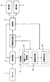
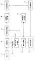
- FIG. 1 is a block diagram illustrating an example of a schematic configuration of an X-ray CT apparatus according to a first embodiment. It is a graph for demonstrating the process which the X-ray CT apparatus which concerns on 1st Embodiment performs. It is a graph for demonstrating the process which the X-ray CT apparatus which concerns on 1st Embodiment performs. It is a graph for demonstrating the process which the X-ray CT apparatus which concerns on 1st Embodiment performs. It is a graph for demonstrating the process which the X-ray CT apparatus which concerns on 1st Embodiment performs. It is a flowchart showing an example of operation
- a subject is an object, but the object is not limited to this.
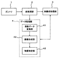
- the X-ray CT apparatus includes a gantry 1, a preprocessing unit 2, a reconstruction processing unit 3, and a data processing unit 4.
- the X-ray CT apparatus of this embodiment is provided with a bed, a console, a high voltage generator, and the like, as in general.
- the gantry 1 is used for scanning a subject with X-rays.
- the gantry 1 includes an X-ray tube and an X-ray detector arranged opposite to each other, a rotation mechanism that rotates them, a slip ring mechanism, a tilt mechanism, and a data acquisition unit (Data Acquisition), as in the general case. System (DAS) and the like are provided.
- DAS data acquisition unit
- the gantry 1 scans the subject with X-rays while rotating the X-ray tube and the X-ray detector. Data detected by the X-ray detector is collected by the data collection unit and sent to the preprocessing unit 2.
- the gantry 1 can particularly perform a technique of performing scanning with two X-ray beams having different energies, that is, dual energy CT.
- the energy of X-rays depends on the voltage (tube voltage) applied to the X-ray tube by the high voltage generator.
- dual energy CT there are a slow-kV switching method, a dual source method, a fast-kV switching method, and the like.
- the Slow-kV Switching method is a method (two-rotation method) in which scanning is performed with the second tube voltage after scanning with the first tube voltage.
- the dual source method is a method (two-tube method) in which a gantry having two X-ray tubes is used and different tube voltages are applied to these X-ray tubes to perform scanning.
- the Fast-kV Switching method is a method (high-speed switch method) for switching the tube voltage for each view while rotating the X-ray tube and the X-ray detector.
- the preprocessing unit 2 performs predetermined preprocessing (processing performed before the image reconstruction processing) on the detection data sent from the gantry 1. Examples of the pre-processing include a process for calculating the logarithm of data, reference correction, water correction, beam hardening correction, and body motion correction. Data generated by the preprocessing unit 2 is called projection data. The projection data generated by the preprocessing unit 2 is sent to the reconstruction processing unit 3 and the data processing unit 4.
- the gantry 1 and the preprocessing unit 2 function as an example of a “generation unit”.
- the reconstruction processing unit 3 generates image data of the subject by performing a reconstruction process on the projection data generated by the preprocessing unit 2.
- the reconstruction process is an arithmetic process for calculating back the X-ray absorption coefficient distribution of the subject from the projection data. Examples of the arithmetic processing include a two-dimensional Fourier transform method, a convolution / back projection method, and a fan beam / convolution / back projection method.
- the reconstruction processing unit 3 may be configured to generate image data by performing reconstruction processing on the projection data obtained by the data processing unit 4. This process will be described later.
- the data processing unit 4 performs predetermined data processing on the projection data generated by the preprocessing unit 2 to identify the type of substance contained in the subject.
- the data processing unit 4 includes a projection data conversion unit 41, an image forming unit 42, and a substance specifying unit 43.
- the projection data conversion unit 41 functions as an example of a “conversion unit”
- the image formation unit 42 functions as an example of an “image formation unit”
- the substance identification unit 43 functions as an example of a “specification unit”.
- the projection data conversion unit 41 converts the first and second projection data obtained by the dual energy CT method into two projection data corresponding to two predetermined reference materials.
- the projection data conversion unit 41 uses the technique described in Patent Document 1 to convert each of the first and second projection data into two predetermined values corresponding to two reference substances. This is expressed as a linear combination of a reference value and the two projection data. That is, the two coefficients in this linear combination become the target two projection data. Details of this processing example will be described later.
- the image forming unit 42 reconstructs the two projection data obtained by the projection data conversion unit 41, thereby forming two reference material images corresponding to the two reference materials.
- the reference material image represents the distribution of the linear attenuation coefficient in the object.
- the linear attenuation coefficient indicates the proportion of energy that attenuates when incident X-rays pass through a single thickness of material.
- the information obtained by this reconstruction processing is a linearly combined image in which the coefficients of two reference values are composed of two reference substance images. That is, the two coefficients in the linear combination image become the two target reference material images (reconstructed images).
- This reconfiguration process is performed in the same manner as the reconfiguration processing unit 3.
- the reconstruction processing unit 3 may perform the reconstruction processing instead of the image forming unit 42. In that case, the image forming unit 42 is unnecessary. Details of an example of processing executed by the image forming unit 42 or the reconstruction processing unit 3 will be described later.
- the two reference values are used to represent the linear attenuation coefficient of the projection data as a linear combination.
- the two reference values may be linear attenuation coefficients of the two reference materials.
- the two reference values may be arbitrary values.
- the first projection data (high energy side) generated by the preprocessing unit 2 is represented by g H
- the second projection data (low energy side) is represented by g L
- the projection data conversion unit 41 generates two projection data L 1 and L 2 by performing conversion shown in the following equation (1) on the projection data g H and g L.
- D is a determinant of the 2 ⁇ 2 matrix on the right side of the following equation (2); ⁇ > 1 , 2 H, L are energy averaged line attenuation coefficients described in Patent Document 1; Respectively.
- the image forming unit 42 reconstructs the two projection data L 1 and L 2 shown in Expression (2), respectively, thereby two reference substance images corresponding to the two reference substances (c 1 in the following Expression (3)). , C 2 ).
- the linear attenuation coefficient ⁇ of an arbitrary substance is expressed by a linear combination (linear combination) using two reference values ⁇ 1 and ⁇ 2 and two reference substance images c 1 and c 2 as shown in the following equation (3). Image).
- E is the energy of X-rays
- ⁇ 1 (E) is the linear attenuation coefficient (reference value) of the first reference material at energy E
- ⁇ 2 (E) is the linear attenuation coefficient (reference value) of the second reference material at energy E
- c 1 (E, x, y) is the abundance of the first reference substance in the pixel located at the coordinates (x, y)
- c 2 (E, x, y) is the abundance of the second reference material in the pixel located at the coordinates (x, y);
- the reference substance images (presence ratios) c 1 and c 2 are coefficients when the linear attenuation coefficient ⁇ of an arbitrary substance is expressed as a function of the linear attenuation coefficients ⁇ 1 and ⁇ 2 of the two reference substances. It is an index showing how similar a substance is to each reference substance.
- the first reference substance is a contrast medium (iodine concentration 50 [mgI / ml]) and the second reference substance is water will be described in particular as an example.
- the substance specifying unit 43 specifies the type of the target substance based on the correlation between the two reference substance images formed by the image forming unit 42.
- the target substance indicates a substance that is a target of the type specific processing in this embodiment.
- the substance specifying unit 43 sets two reference substance images c 1 and c in a coordinate system determined in advance based on two reference values ⁇ 1 and ⁇ 2 for a predetermined target substance. The coordinates corresponding to 2 are determined.
- the substance specifying unit 43 converts the plurality of coordinates in the coordinate system obtained in advance for a plurality of predetermined substances and the coordinates corresponding to the two reference substance images c 1 and c 2 determined in the previous process. Based on this, the type of the target substance is specified.
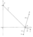
- a two-dimensional coordinate system based on two existence rates c 1 and c 2 as shown in FIG. 2 can be applied.
- This coordinate system the existence ratio c 1 of the contrast medium as a first reference material on the vertical axis, in which the existence ratio c 2 of water as a second reference material was the horizontal axis.
- the coordinates in this coordinate system are described in the order of the coordinate on the vertical axis and the coordinate on the horizontal axis. That is, the coordinates in this coordinate system are described as (c 1 , c 2 ).
- a reference coordinate P (1, 0) on the vertical axis that is, a base in the vertical axis direction
- a vector corresponding to a contrast medium existence rate c 1 of 100% is applied.
- a reference coordinate Q (0, 1) on the horizontal axis that is, a base in the horizontal axis direction
- a vector corresponding to 100% water abundance c 2 is applied.
- the substance specifying unit 43 treats the set of reference substance images (c 1 , c 2 ) in the linear combination image obtained by the image forming unit 42 as the coordinates of this coordinate system.
- the coordinate system (base) is set so that the set of the reference substance image and the coordinates are the same, but the present invention is not limited to this.
- a coordinate system in which the coordinate axes are expanded and contracted can be applied by multiplying c 1 and c 2 by a coefficient.
- assigned a c 1 on the vertical axis, but are assigned to c 2 on the horizontal axis may be the other way round.
- other coordinate systems such as an oblique coordinate system can be used. That is, the coordinate system in this embodiment is sufficient as long as it can represent the correlation between two reference substance images in a linear combination image, and the specific mode is arbitrary.
- the above “plurality of substances” used for processing by the substance specifying unit 43 may be any substance. Moreover, the number is also arbitrary.
- the contrast agent and water correspond to a plurality of substances.
- the “plural substances” and the substance used for generating the base are the same, but the present invention is not limited to this.
- a case where two substances of contrast medium and water are used as “reference substances” and five substances of contrast medium, water, calcium carbonate, fat and uric acid are applied as “multiple substances” will be described later.
- the method for obtaining coordinates corresponding to multiple substances is also arbitrary. For example, there are a method of actually measuring the substance and obtaining coordinates, and a method of calculating coordinates taking into account the linear attenuation coefficient of other substances.
- the material is scanned with X-rays to generate projection data, and a linear attenuation coefficient for each pixel based on the material is expressed as a linear combination, and coordinates corresponding to the set of coefficients are determined. Is done.
- E Low and E High are two types of X-ray energies; ⁇ (E Low ) is the linear attenuation coefficient of the material at lower energy E Low ; ⁇ (E High ) is the linear attenuation coefficient of the substance at the higher energy E High ; Respectively.
- the substance specifying unit 43 specifies the type of the target substance based on the plurality of coordinates for the plurality of substances acquired in this way and the coordinates determined by the substance specifying unit 43 for the target substance.
- the substance specifying unit 43 (1) obtains an area in the coordinate system based on the plurality of coordinates, and (2) determines the type of the object substance based on the position of the coordinates of the object substance with respect to this area. Identify.
- a graph connecting a plurality of coordinates is used as the region in the coordinate system will be described.
- the displayed graph is merely used to assist understanding of the embodiment. The same applies to regions in the coordinate system described later.
- An area in the coordinate system corresponds to a set of coordinates in the coordinate system
- a graph corresponds to a set of coordinates located on the area itself or on the outer periphery thereof.
- a line segment formula is obtained by calculating a formula of a straight line that passes through these two coordinates (that is, an inclination and an intercept), and extracting a portion of the straight line having the two coordinates at both ends.
- the same calculation may be performed on any combination of two coordinates.
- the coordinates on the line segment L1 correspond to the iodine concentration of the contrast agent.
- coordinates P1, P2, P3, P4, and P5 on the line segment L1 have iodine concentrations of 25 [mgI / ml], 20 [mgI / ml], 15 [mgI / ml], 10 [mgI / ml], 5 Each corresponds to [mgI / ml].
- the coordinate P corresponds to 50 [mgI / ml]
- the coordinate Q corresponds to 0 [mgI / ml] (simple water). That is, the iodine concentration increases as it approaches the coordinate P on the line segment L1, and the iodine concentration decreases as it approaches the coordinate Q.
- the concentration of the substance can be represented as a graph.
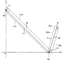
- FIG. 3 shows an example of a graph in the case where five substances of contrast medium, water, calcium carbonate, fat and uric acid are employed.
- FIG. 3 shows the coordinates P of the contrast agent, the coordinates Q of the water, the coordinates R of the calcium carbonate, the coordinates S of the fat, and the coordinates T of the uric acid.
- a line segment L1 connecting the coordinates P and Q corresponds to the iodine concentration of the contrast agent
- a line segment L2 connecting the coordinates R and Q corresponds to the calcium carbonate concentration.
- the connecting line segment L3 corresponds to the fat concentration
- the connecting line segment L4 connecting the coordinates T and Q corresponds to the uric acid concentration.
- the density decreases as it approaches the coordinate Q, and the density increases as the distance from the coordinate Q increases.
- the four line segments L1 to L4 intersect each other only at the coordinate Q. This is because the line segments L1 to L4 are separated from each other except the coordinate Q corresponding to the concentration 0 (simply water), that is, the coordinates corresponding to the four substances (contrast medium, calcium carbonate, fat and uric acid). Are separated from each other in the coordinate system. In other words, if the position of the line segment in the coordinate system is different, the corresponding substance is also different.
- the substance specifying unit 43 specifies the type of the target substance based on the positional relationship between the coordinates of the target substance determined by the substance specifying unit 43 and the graph.
- the substance specifying unit 43 determines whether the coordinates of the target substance are located on any of these line segments L1 to L4. To do.
- the substance specifying unit 43 determines the type of the target substance based on the position of the coordinates in the line segment Li. Is identified. This type includes not only the substance name of the target substance but also its concentration (that is, the component ratio between the target substance and water).
- the substance specifying unit 43 does not correspond to any of the substances corresponding to these line segments L1 to L4. And get the result.
- a polygon formed by connecting these coordinates can be formed as an area in the coordinate system.
- the area defined by this polygon corresponds to a mixture of these reference substances.
- the mixture means a substance defined when the component ratio of each reference substance is 0 to 100% and the sum of the component ratios of all reference substances is 100%. Therefore, this mixture includes those containing only one or two of the three or more reference substances as components.
- a material having only one reference material as a component corresponds to a vertex of the polygon, and a material having only two reference materials as a component corresponds to a side of the polygon.
- a case where three reference substances, contrast medium, water, and calcium carbonate are used as reference substances will be described.
- a polygon (triangle) A having coordinates P, Q, and R corresponding to the contrast medium, water, and calcium carbonate as vertices is obtained.
- the regions corresponding to the sides PQ (line segment L1) and QR (line segment L2) of the polygon A represent the contrast agent concentration and the calcium carbonate concentration, respectively, as described above.
- a region corresponding to the side PR (line segment L5) represents a component ratio of the contrast agent and calcium carbonate in the mixture of the contrast agent and calcium carbonate.
- the component ratio of the contrast agent increases as it approaches the apex P
- the component ratio of calcium carbonate increases as it approaches the apex R.
- the inner region of the polygon A that is, the region excluding the line segments L1, L2, and L5 from the region on the polygon A corresponds to a mixture of all these three reference substances.
- the component ratio of the contrast agent increases as it approaches the apex P
- the component ratio of calcium carbonate increases as it approaches the apex R.
- concentration of the said mixture reduces, so that the vertex Q equivalent to water is approached.
- the substance specifying unit 43 determines whether or not the determined coordinates of the target substance are located on the polygon. When it is determined that the coordinates are located outside the polygon, the substance specifying unit 43 determines that the target substance is not a mixture corresponding to the polygon.
- the substance specifying unit 43 determines that the target substance is the mixture. Furthermore, the substance specifying unit 43 obtains a component ratio of three or more reference substances constituting the target substance based on the coordinate position of the target substance.
- This distribution information is, for example, standard deviation information of noise mixed in projection data obtained by this X-ray CT apparatus.
- This distribution information is stored in the substance specifying unit 43.
- FIG. 1 An example of the distribution of coordinates for each of the contrast medium, water and calcium carbonate is shown in FIG.
- the coordinate distribution range for the contrast agent is denoted by Pa
- the coordinate distribution range for water is denoted by Qa
- the coordinate distribution range for calcium carbonate is denoted by Ra.
- the substance specifying unit 43 obtains a two-dimensional area including a graph corresponding to the substance based on the standard deviation information. An example of this process will be described. First, the substance specifying unit 43 obtains two line segments L1a and L1b that connect the distribution range Pa and the distribution range Qa. As the line segments L1a and L1b, for example, those in contact with both the distribution ranges Pa and Qa and not intersecting each other are used. Thereby, a region B surrounded by the distribution ranges Pa and Qa and the line segments L1a and L1b is obtained. Similarly, a region C surrounded by the distribution ranges Ra and Qa and the line segments L2a and L2b is obtained.
- the region B is used as a distribution range of contrast agent concentration coordinates reflecting measurement errors.
- coordinates that are not on the line segment L1 are associated with density values based on the line segment L1.
- a straight line orthogonal to the line segment L1 can be obtained at each position on the line segment L1, and the density of coordinates positioned on this line can be set equal.
- the concentration is similarly set for the region C indicating the distribution range of the calcium carbonate concentration reflecting the measurement error.
- the substance specifying unit 43 specifies the type of the target substance based on the coordinates of the determined target substance and the positional relationship between the regions B and C. For example, when the coordinates of the target substance are located on the area B, the substance specifying unit 43 specifies that the target substance is a contrast agent, and further, the coordinates and the concentration set to the coordinates on the area B Based on the above, the concentration of the target substance is specified.
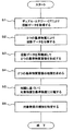
- (S1) First, photographing with dual energy CT is performed with the gantry 1.
- the preprocessing unit 2 converts the data collected by the gantry 1 into projection data. Thereby, first and second projection data having different energies are generated.
- the first and second projection data are sent to the data processing unit 4.
- the projection data conversion unit 41 expresses the linear attenuation coefficient for each pixel based on the projection data generated in step 1 as a linear combination of the linear attenuation coefficients of the two reference substances, thereby obtaining the projection data of the two reference substances. Decompose. By this step 2, the first and second projection data are converted into two projection data corresponding to the two reference materials.
- the image forming unit 42 reconstructs the linear combination obtained in step 2 to form a linearly combined image. Thereby, two reference material images are obtained.
- the substance specifying unit 43 obtains the correlation between the two reference substance images obtained in step 3.
- the corresponding coordinates (c 1 (x, y), c 2 (x, y)) in a predetermined two-dimensional coordinate system are obtained for each pixel (x, y) of the two reference material images. .
- the substance specifying unit 43 decomposes the target substance into two reference substances based on the correlation obtained in step 4.
- the target substance is decomposed into a contrast medium and water.
- the substance specifying unit 43 specifies the type of the target substance based on the decomposition result in step 5. This identification result is displayed on a display (not shown), for example. The identification result is stored in a storage device of the X-ray CT apparatus or a storage device on the network.
- This X-ray CT apparatus generates projection data by the gantry 1 and the preprocessing unit 2.
- the first and second projection data are generated by scanning the target with dual energy CT, that is, first and second X-rays having different energies.
- the X-ray CT apparatus further includes a projection data conversion unit 41, an image forming unit 42, and a substance specifying unit 43.
- the projection data conversion unit 41 converts the first and second projection data into two projection data (new projection data) corresponding to two predetermined reference materials.
- the image forming unit 42 reconstructs two pieces of projection data to form two reference material images corresponding to the two reference materials.
- the substance specifying unit 43 specifies the type of the target substance based on the correlation between the two reference substance images.
- the projection data conversion unit 41 converts each of the first and second projection data into two linear values including two predetermined reference values corresponding to two reference substances and two projection data. You may comprise so that it may express as a coupling
- the image forming unit 42 may be configured to form a linear combination image composed of two reference values and two reference substance images by reconstructing the linear combination.
- the substance specifying unit 43 determines coordinates corresponding to two reference substance images in a coordinate system determined in advance based on two reference values for the target substance, and a coordinate system obtained in advance for a plurality of substances The type of the target substance may be specified based on the plurality of coordinates and the determined coordinates.
- two reference values may be a linear attenuation coefficient of two reference substances determined beforehand.
- the coordinate system may be a two-dimensional coordinate system stretched by two bases based on the linear attenuation coefficients of two reference materials.
- the substance specifying unit 43 may be configured to specify the type of the target substance based on the coordinate position of the target substance with respect to the region in the coordinate system based on a plurality of coordinates.
- the substance specifying unit 43 sets a line segment connecting the coordinates of the first substance and the coordinates of the second substance in the coordinate system in the coordinate system.
- the coordinates of the target substance are located on this line segment, the component ratio between the first substance and the second substance may be obtained based on the position.
- the substance specifying unit 43 obtains a polygon connecting the coordinates of the three or more substances in the coordinate system as an area in the coordinate system, and coordinates of the target substance Is located on the polygon, the component ratio of three or more substances may be obtained based on the position.
- the area in the coordinate system when the coordinates of three or more substances are considered is not limited to a polygon.
- the region in the coordinate system may generally be a figure based on the coordinates of three or more substances, that is, an arbitrary figure formed in consideration of these coordinates.
- a figure that passes or includes the coordinates of three or more substances can be used as the region in the coordinate system.
- the outer peripheral line of the figure does not need to be a straight line, and the coordinates of the substance do not need to be on the outer peripheral line of the figure.
- the component ratio of three or more substances is calculated based on the position.
- the substance specifying unit 43 determines each of the first and second coordinates determined for the first and second target substances and the coordinates of the water. Two connecting line segments are obtained as a region in the coordinate system, and based on the positional relationship between these line segments, the first target substance and the second target substance are configured to identify whether or not they are the same type. Also good.
- the substance specifying unit 43 stores in advance standard deviation information of noise mixed in the projection data, obtains a two-dimensional area including an area in the coordinate system based on the standard deviation information, and targets the target substance for the two-dimensional area
- the type of the target substance may be specified based on the position of the coordinates.
- the characteristics of the target substance are expressed as coordinates in a predetermined coordinate system, and the type of the target substance can be specified based on the coordinates and a plurality of coordinates for the plurality of substances. it can. Therefore, even a substance with a close CT value ratio can be identified with high accuracy by referring to the coordinates.
- the component ratio of the substance constituting the target substance can be obtained. Furthermore, it is possible to determine whether two or more target substances are the same or different from each other by referring to the region in the coordinate system.
- FIG. 1 A schematic configuration of the X-ray CT apparatus of this embodiment is shown in FIG.
- the X-ray CT apparatus includes the configuration described in the first embodiment.
- the X-ray CT apparatus includes a gantry 1, a preprocessing unit 2, a reconstruction processing unit 3, a data processing unit 4, a control unit 5, a display unit 6, and an operation unit 7.
- the data processing unit 4 is provided with a projection data conversion unit 41, an image forming unit 42, and a substance specifying unit 43.
- the same components as those in the first embodiment have the same functions as those in the first embodiment unless otherwise specified.
- specification part 43 calculates
- This line segment represents the component ratio in the mixture of the target substance and water, that is, the concentration of the target substance.
- the data processing unit 4 obtains the distribution of the target substance in the imaging region by applying the processing of the first embodiment to each position of the imaging region of the object (subject, etc.). This distribution information is input to the reconstruction processing unit 3.
- the distribution information includes information indicating the position of the target substance in the imaging region and information indicating the concentration.
- the reconstruction processing unit 3 Upon receiving the distribution information and the projection data, the reconstruction processing unit 3 performs a reconstruction process on the distribution region of the target substance in the projection data, thereby forming a distribution image representing the distribution of the target substance (for example, the concentration distribution). To do. As an example of this process, the reconstruction processing unit 3 identifies a pixel corresponding to the existence position based on the existence position of the target substance indicated in the distribution information. Then, the reconstruction processing unit 3 reconstructs an image only for the specified pixel based on the projection data. As another process, the reconstruction processing unit 3 performs a normal reconstruction process based on the projection data, and extracts only the pixels corresponding to the above existing position from the image obtained thereby. The reconstructed image obtained by these methods is the above distribution image.
- the reconstruction processing unit 3 performs a normal reconstruction process based on the projection data, and extracts only the pixels corresponding to the above existing position from the image obtained thereby. The reconstructed image obtained by these methods is the above distribution image.
- the control unit 5 receives the designation of the position on the line segment representing the concentration of the target substance, and displays the distribution image on the display unit 6 in a manner corresponding to the designated position. This process will be described below.
- This X-ray CT apparatus is provided with a user interface for changing the concentration of the target substance.
- This user interface may be displayed on the display unit 6 based on software, or may be hardware.
- Hardware includes dials and slide levers.
- an image imitating a dial or a slide lever can be displayed on the display unit 6 and operated by the operation unit 7.
- the control unit 5 displays the image shown in FIG. 8 on the display unit 6 based on the graph shown in FIG.
- This image includes a coordinate system shown in FIG. 2, a line segment image D, and a slider E.
- a coordinate system shown in FIG. 2 On the coordinate axis of the coordinate system, character strings “contrast medium” and “water” indicating the substance name are attached.
- the line segment image D shows the line segment L1.
- the slider E is movable on the line segment image D (see double-sided arrow in the figure). The slider E is moved by, for example, a drag operation with the mouse of the operation unit 7.
- the user designates the concentration of the contrast agent by moving the slider E to a desired position. More specifically, the line segment image D and the line segment L1 are associated in advance, and the control unit 5 specifies the position of the line segment L1 corresponding to the position of the slider E, that is, the concentration of the contrast agent.
- the control unit 5 changes the display mode of the distribution image according to the designated density.
- the display mode changing process includes changing the pixel value (luminance, color, etc.) and changing the pattern.
- the control unit 5 displays the slider E at a position corresponding to a predetermined density in the designated distribution image.
- the user moves the slider E to a desired position.
- the control unit 5 changes the display mode of the distribution image according to the position of the slider E after movement.
- control unit 5 causes the display unit 6 to display an input area for inputting the concentration information of the target substance.
- the user inputs a desired density value in the input area using the operation unit 7 (for example, a keyboard).
- the input area may be an object that allows a desired one to be selected from a plurality of density options, such as a pull-down menu.
- the distribution image when the density is higher than the initial value may be referred to as an emphasized image.
- the distribution image when the density is lowered from the initial value may be referred to as a suppression image.
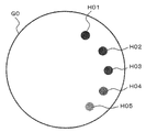
- FIG. 9A shows a distribution image (original image) G0 as a monochromatic X-ray image of 60 keV.
- the actual image and the display luminance are reversed. That is, in the actual image, the higher the concentration of the target substance, the higher the display luminance. In FIG. 9A, the higher the concentration, the lower the display luminance.
- Monochromatic X-ray image is defined by the following equation (5).
- CT number is the CT value
- ⁇ is the linear attenuation coefficient of the target substance shown in Formula (5)
- ⁇ water is the linear attenuation coefficient of water
- Distribution images H01, H02, H03, H04, and H05 of contrast agents having various concentrations are depicted.
- Distribution images H01, H02, H03, H04, and H05 have concentrations of 25 [mgI / ml], 20 [mgI / ml], 15 [mgI / ml], 10 [mgI / ml], and 5 [mgI / ml], respectively. It corresponds to.
- FIG. 9B shows an enhanced image G1 based on the original image G0.
- distribution images H11, H12, H13, H14, and H15 respectively corresponding to the distribution images H01, H02, H03, H04, and H05 in the original image G0 are depicted.
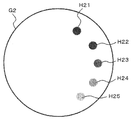
- FIG. 9C shows a suppression image G2 based on the original image G0.
- distribution images H21, H22, H23, H24, and H25 respectively corresponding to the distribution images H01, H02, H03, H04, and H05 in the original image G0 are depicted.
- the control unit 5 specifies a pixel whose coordinates are located on a line segment L1 (see FIG. 2) indicating the concentration of the contrast agent.
- the control unit 5 sets the abundance ratio c 1 of the contrast agent shown in Expression (3) to 1000, sets the abundance ratio c 2 of water to 0, and sets these to the expression ( By assigning to 2a) and (2b), the enhanced image G1 is generated.
- the control unit 5 sets the presence rate c 1 of the contrast agent to 0, sets the presence rate c 2 of water to 1000, and substitutes these into the equations (2a) and (2b), thereby suppressing the suppression image.
- G2 is generated.
- the control unit 5 causes the display unit 6 to display the generated emphasized image G1 and suppression image G2.
- the line segment in the coordinate system represents a mixture of a substance and water, and the position on the line segment corresponds to the concentration.
- the concentration of the contrast agent can be calculated by the following equation.
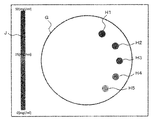
- FIG. 10 shows the density calculated using the equation (6) by extracting the coefficients c 1 (x, y) and c 2 (x, y) whose coordinates are located on the line segment L1 indicating the density of the contrast agent.
- An example of a display mode in the case of displaying in color is schematically shown.
- the distribution image G five distribution images H1, H2, H3, H4, and H5 are depicted.
- the relationship between the density and the display color is indicated by a color bar J.
- concentration of a several substance in color it is also possible to comprise so that a distribution image may be displayed with a different color for every substance.
- the X-ray CT apparatus of this embodiment has the following operation in addition to the operation of the first embodiment.
- One of the substances is a solvent (for example, water).
- the substance specifying unit 43 obtains a line segment connecting the coordinates of the target substance and the coordinates of the solvent.
- the reconstruction processing unit 3 forms a distribution image representing the distribution of the target substance by performing a reconstruction process on the distribution area of the target substance in the projection data.
- the control unit 5 (display image generation unit) receives the designation of the position on the line segment, generates a distribution image (display image) having a mode corresponding to the designated position, and causes the display unit 6 to display the distribution image.
- a line segment image representing a line segment is displayed on the display unit 6 by the control unit 5, and the control unit 5 receives the fact that the position on the line segment image has been designated using the operation unit 7.
- a position on the line segment corresponding to the designated position can be specified, and the distribution image can be displayed in a manner corresponding to the specified position.
- an input area for inputting the concentration information of the substance is displayed on the display unit 6, and further, when the concentration information of the target substance is input to the input area using the operation unit 7, the control unit 5 ( (A density calculation unit, a display image generation unit) can specify a position on a line segment corresponding to the density information, and generate and display a distribution image having an aspect corresponding to the specific position.
- the control unit 5 (A density calculation unit, a display image generation unit) can specify a position on a line segment corresponding to the density information, and generate and display a distribution image having an aspect corresponding to the specific position.
- control unit 5 can be configured to change the display color of the distribution image according to the designated position on the line segment.
- control unit 5 can be configured to change the display color of the distribution image according to the type of the target substance specified by the substance specifying unit 43.
- control unit 5 can be configured to change the display color of the distribution image according to both the type of the target substance and the designated position on the line segment.
- an enhanced image and a suppressed image can be formed and displayed.
- concentration of the substance can be expressed visually, an intuitive understanding of the concentration becomes possible.
- FIG. 11 shows a schematic configuration of the X-ray CT apparatus of this embodiment.
- This X-ray CT apparatus includes the configuration described in the first embodiment. Although not shown, the X-ray CT apparatus may further include the configuration described in the second embodiment.
- the X-ray CT apparatus includes a gantry 1, a preprocessing unit 2, a reconstruction processing unit 3, a data processing unit 4, a pixel value ratio calculation unit 8, a substance specifying unit 9, and a specific image forming unit 10.
- the specific control unit 11 is included.
- the data processing unit 4 is provided with a projection data conversion unit 41, an image forming unit 42, and a substance specifying unit 43.
- the substance specifying unit 9 and the specifying control unit 11 each function as an example of a “specifying unit”.
- the same components as those in the first embodiment have the same functions as those in the first embodiment unless otherwise specified.
- the substance specifying process described in the first embodiment is executed by the data processing unit 4, and the substance specifying process described in Non-Patent Document 1 is executed by the pixel value ratio calculating unit 8 and the substance specifying unit 9.
- the reconstruction processing unit 3 forms first and second images by performing reconstruction processing on each of the first and second projection data obtained by the dual energy CT.
- the pixel value ratio calculation unit 8 calculates the ratio of pixel values (CT values) in the first and second images as described in Non-Patent Document 1. This process associates pixels between the first image and the second image, and calculates the ratio of the CT values of the two associated pixels.
- the substance specifying unit 9 specifies the type of the target substance based on the CT value ratio calculated by the pixel value ratio calculating unit 8 by using the method described in Non-Patent Document 1.
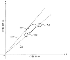
- FIG. 12 An example of the distribution of CT value ratios obtained for these substances is shown in FIG.
- the CT value at the tube voltage of 80 kV is on the x axis
- the CT value at the tube voltage of 135 kV is on the y axis. Therefore, the slope of a straight line passing through the origin and arbitrary coordinates corresponds to the CT value ratio.
- Distribution areas K1, K2, and K3 indicate distributions for uric acid, cartilage, and soft tissue, respectively.
- uric acid and cartilage have different CT value ratios and can be distinguished from each other, but uric acid and soft tissue are difficult to distinguish because the CT value ratio is close. is there.
- the straight lines M1 and M2 represent the maximum value and the minimum value of the CT value ratio of uric acid, respectively.
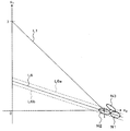
- FIG. 13 shows an example of the distribution of coordinates of uric acid, cartilage and soft tissue obtained by the method described in the first embodiment.
- the vertical axis and the horizontal axis are set based on the contrast medium and water, respectively.
- Distribution regions N1, N2, and N3 indicate distributions for uric acid, cartilage, and soft tissue, respectively.
- the straight line L6 is a straight line showing the distribution state of the coordinates of uric acid.
- the straight lines L6a and L6b indicate the upper and lower limits of the linear distribution range corresponding to the spread of the uric acid distribution region, respectively (see the first embodiment). Although illustration of straight lines is omitted for cartilage and soft tissue, the direction of the straight lines can be easily grasped from the form.
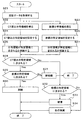
- the reconstruction processing unit 3, the pixel value ratio calculating unit 8, and the substance specifying unit 9 obtain the CT value ratio distribution information shown in FIG. 12, that is, the distribution regions K1, K2, and K3 in the manner described above (S22). Further, the data processing unit 4 obtains the coordinate distribution information shown in FIG. 13, that is, the distribution regions N1, N2, and N3 as described above (S23). The distribution information is sent to the specific control unit 11.
- the CT value ratio distribution information may be referred to as first distribution information
- the coordinate distribution information may be referred to as second distribution information.
- the identification control unit 11 identifies each of the three substances based on the first and second distribution information.
- the specific control unit 11 first obtains straight lines M1 and M2 shown in FIG. 12 and straight lines L6a and L6b shown in FIG. Even if the straight lines M1, M2 and the straight lines L6a, L6b are created from the data obtained by the current measurement, the measurement data obtained in advance or specified values (theoretical values, standard values, etc.) ). Further, the specific control unit 11 may obtain, for each substance, a straight line based on the CT value ratio distribution region or a straight line based on the coordinate distribution region. In this way, a specific region sandwiched between the straight lines M1 and M2 and a specific region sandwiched between the straight lines L6a and L6b are obtained (S24, S25).
- the specific control unit 11 determines whether the distribution regions K2 and K3 of the CT value ratios of the cartilage and the soft tissue are included in the specific region sandwiched between the straight lines M1 and M2 (S26). This processing may be to determine whether the distribution areas K2 and K3 themselves are included in the specific area, or to determine whether the straight line is included in the specific area when the straight line is obtained as described above. Good.
- a range of the length of the straight line is determined in advance, and when the straight line is included in the specific region within the range, it may be determined that the straight line is included in the specific region. Good.
- the specific control unit 11 determines whether the distribution areas N2 and N3 of the coordinates of the cartilage and the soft tissue are included in the specific area sandwiched by the straight lines L6a and L6b (S27). This process can be executed in the same manner as in the case of the CT value ratio.
- the specific control unit 11 determines whether the CT value ratio distribution areas K2 and K3 are included in the specific area and whether the coordinate distribution areas N2 and N3 are included in the specific area. Based on this, uric acid, cartilage and soft tissue are discriminated.
- the specific control unit 11 includes the CT value ratio distribution region in the specific region (S28: Yes), and includes the coordinate distribution region in the specific region (S29: Yes). If it is determined, the substance corresponding to these distribution regions is determined to be uric acid (S30).
- the specific control unit 11 determines that the CT value ratio distribution region is included in the specific region (S28: Yes), and the coordinate distribution region is not included in the specific region (S29: No). If it is determined, the substance corresponding to these distribution regions is determined to be soft tissue (S31).
- the specific control unit 11 determines that the CT value ratio distribution region is not included in the specific region (S28: No), and the coordinate distribution region is included in the specific region (S32: Yes). If so, it is determined that the substance corresponding to these distribution regions is cartilage (S33).
- the specific control unit 11 determines that the CT value ratio distribution region is not included in the specific region (S28: No), and the coordinate distribution region is not included in the specific region (S32: No). If so, the substance corresponding to these distribution regions is determined not to be uric acid, cartilage or soft tissue. This is the end of the description of this processing example.
- the specific image forming unit 10 forms at least one of the effective atomic number image, the density image, and the monochrome X-ray image (sometimes referred to as a specific image).
- an image (reference material image) representing the distribution of each reference material formed based on the coefficients c 1 and c 2 in the linear combination (formula (3)) described in the first embodiment is used as a patent. It is executed by combining the methods described in Document 1.
- the effective atomic number image is an image representing the distribution of effective atomic numbers in the object.
- the density image is an image representing the density distribution of the substance in the target substance.
- the monochromatic X-ray image is an image that simulates the case where the target substance is scanned with X-rays having a single energy.
- the specific image forming unit 10 capable of forming these images functions as an example of a “forming unit”.
- the substance specifying unit 43 of this embodiment is formed by the specific image forming unit 10 for each of a plurality of target substances obtained by the processing described in the first embodiment, and for each of these target substances. Based on the effective atomic number image, the density image, and / or the monochromatic X-ray image, it is possible to specify the types of these target substances.
- the processing described in the first embodiment is based on the plurality of coordinates in the coordinate system obtained in advance for a plurality of substances and the coordinates determined by the substance specifying unit 43 for the target substance. Is specified.
- the effects of the first embodiment can be obtained, the distribution state of the coordinates of each substance in the coordinate system similar to the first embodiment, and the CT of each substance
- the type of the substance can be specified based on both the distribution state of the value ratio. Therefore, it is possible to further improve the identification accuracy of the substance contained in the object.
- an effective atomic number image, a density image, and / or a monochromatic X-ray image can be formed, so that the distribution state of the substance can be visually grasped. It is. Further, by combining the substance specifying process using the coordinate system and the substance specifying process using these images, it is possible to further improve the specifying accuracy of the substance included in the object.
- FIG. 15A it is assumed that three coordinates V1, V2, and V3 are obtained for three target substances. These coordinates V1, V2, and V3 are not located on the same straight line. In this case, this coordinate system and the coordinates V1, V2, and V3 are displayed on the display unit. The user refers to the displayed coordinate system and the coordinates V1, V2, and V3, and arbitrarily sets a region in the coordinate system using the operation unit. At this time, as shown in FIG. 15B, for example, the region W is set so as to include coordinates V1, V2, and V3.
- the region W is used as a distribution range of the coordinates of the contrast agent concentration reflecting an error caused by an unknown component of the object.
- a density value is associated with a non-coordinate based on the line segment. This association is performed, for example, in the same manner as shown in FIG.
- the substance specifying unit 43 specifies the type of the target substance based on the determined coordinates of the target substance and the positional relationship between the regions W, for example, by the same method as shown in FIG.
- the substance can be specified with high accuracy by the user's judgment.
- the generation unit scans the object with N (three or more) X-rays having different energies. N pieces of projection data are generated.
- the conversion unit converts the N projection data into N new projection data corresponding to the N reference substances.
- the image forming unit reconfigures each of the N new projection data converted by the conversion unit, thereby forming N reference material images corresponding to the N reference materials.
- the specifying unit specifies the target substance based on the correlation of the pixel values of the N reference substance images.
- the number of bases of two linear combinations in the above embodiment is N
- the dimension of the two-dimensional coordinate system is N. That is, there is no substantial difference between the case where the number of X-rays having different energies is 2 and the case where it is 3 or more. Therefore, the above embodiment can be generalized as follows when using a plurality of (two or more) X-rays having different energies.
- An X-ray CT apparatus is an apparatus that displays an image in an object based on projection data obtained by scanning the object, and includes a generation unit, a conversion unit, an image formation unit, And a specific part.
- the generation unit generates a plurality of projection data by scanning the object with X-rays having different energies.
- the conversion unit converts the plurality of projection data into a plurality of new projection data corresponding to the plurality of reference substances.
- the image forming unit reconstructs a plurality of new projection data converted by the conversion unit, thereby forming a plurality of reference material images corresponding to the plurality of reference materials.
- the specifying unit specifies the target substance based on the correlation of the pixel values of the plurality of reference substance images.
- an X-ray CT apparatus it is possible to specify the substance contained in the target object with high accuracy, as in the above embodiment. Furthermore, by using three or more X-rays having different energies, it becomes possible to specify a substance with higher accuracy than in the embodiment using two X-rays.
- the substance specifying method according to the embodiment is executed by, for example, the X-ray CT apparatus according to the above-described embodiment.
- the substance specifying method of the embodiment includes a generating step, a converting step, an image forming step, and a specifying step.
- a plurality of projection data is generated by scanning the object with X-rays having different energies.
- the conversion step the plurality of projection data is converted into a plurality of new projection data corresponding to the plurality of reference substances.
- the image forming step a plurality of reference material images corresponding to the plurality of reference materials are formed by reconstructing a plurality of new projection data converted in the conversion step.
- the specifying step the target substance is specified based on the correlation of the pixel values of the plurality of reference substance images.
- the identifying step may identify the target substance by determining whether or not the corresponding pixel values in the plurality of reference substance images have a preset correlation.
- the conversion step may convert a plurality of projection data into a plurality of new projection data corresponding to a plurality of reference materials using a calculation formula including an X-ray attenuation coefficient corresponding to the reference material.
- a display image generation step for generating an image in the object in which the region of the target substance specified in the specifying step can be identified may be further included.
- a display image generation step of generating a display image in which the pixels in the target substance region specified in the specifying step are emphasized or suppressed as compared with pixels in other regions may be further included.
- a concentration calculation step for obtaining concentration information of the target substance from the values of the corresponding pixels in the plurality of reference substance images based on a calculation formula stored in advance may be further included.
- a display image generation step for generating a display image representing density information may be further included.
- a plurality of energy images obtained by reconstructing a plurality of projection data are generated, and in the specifying step, based on correlation of pixel values of a plurality of reference substance images of the plurality of energy images.
- the target substance may be specified.
- the method further includes a forming step of forming at least one of monochromatic X-ray images that reproduces the simulated case, and in the specifying step, the target substance is specified based on the image formed in the forming step. May be.
- a substance with a close CT value ratio can be identified with high accuracy by referring to the coordinates. Further, it is possible to obtain the component ratio of the substances constituting the target substance, and to determine whether two or more target substances are the same or different.
- a substance identification method that takes into account the influence of noise as in the first embodiment, it is possible to identify substances with higher accuracy and accuracy, identify component ratios, separate target substances, and the like. Become.
- an enhanced image and a suppressed image can be formed and displayed as in the second embodiment.
- concentration of the substance can be expressed visually, an intuitive understanding of the concentration becomes possible.
- the substance specifying method in addition to the above effects, based on both the distribution state of the coordinates of each substance and the distribution state of the CT value ratio of each substance.
- the type of substance By specifying the type of substance, it is possible to further improve the identification accuracy of the substance contained in the object.
- an effective atomic number image, a density image, and / or a monochromatic X-ray image can be formed, it is possible to visually grasp the distribution state of the substance.
- by combining the substance specifying process using the coordinate system and the substance specifying process using these images it is possible to further improve the specifying accuracy of the substance included in the object.
- FIG. 1 A configuration example of the image processing apparatus according to the embodiment is shown in FIG.
- the image processing apparatus 100 is connected to the image storage apparatus 300 via a network such as a hospital LAN.
- the image storage apparatus 300 stores an image formed by the X-ray CT apparatus 200.
- the X-ray CT apparatus 200 has a configuration in which, for example, the substance specifying unit 43 is removed from the X-ray CT apparatus (see FIG. 1) of the first embodiment. That is, the X-ray CT apparatus 200 is an apparatus that displays an image in the object based on projection data obtained by scanning the object, and has the following function: X-rays with different energies Generation function that scans an object and generates a plurality of projection data; conversion function that converts a plurality of projection data into a plurality of new projection data corresponding to a plurality of reference materials; a plurality of new data converted by the conversion function Image forming function for forming a plurality of reference material images corresponding to a plurality of reference materials by reconstructing various projection data.
- X-rays with different energies Generation function that scans an object and generates a plurality of projection data
- conversion function that converts a plurality of projection data into a plurality of new projection data corresponding to a plurality of reference materials
- the X-ray CT apparatus 200 sends the formed plurality of reference material images to the image storage apparatus 300 via a network such as a hospital LAN.
- the image storage device 300 is, for example, an image storage communication system (Picture Archiving and Communication Systems; PACS).
- the image processing apparatus 100 processes an image formed by the X-ray CT apparatus 200 and stored in the image storage apparatus 300. Note that it is also possible to input an image to the image processing apparatus 100 via another route. Another example of the route is a recording medium such as a DVD in which an image is stored.
- the image processing apparatus 100 includes an image acquisition unit 101 that performs processing for acquiring an image from the outside.
- the image acquisition unit 101 includes a communication unit that communicates with the image storage device 300 via a network. Furthermore, the image acquisition unit 101 generates, for example, a user interface (display unit, operation unit, etc.) for selecting an image to be acquired and a signal for acquiring the selected image, and controls the communication unit. A communication control unit that causes the image storage device 300 to transmit this signal is included.
- the image acquisition unit 101 includes a reading unit (such as a drive device) that can read information recorded on the recording medium.
- the image acquired by the image acquisition unit 101 is stored in the storage unit 102.
- the storage unit 102 includes a storage device such as a hard disk drive.
- the image formed by the X-ray CT apparatus 200 as described above is stored in the storage unit 102.
- This image reconstructs a plurality of new projection data obtained by converting a plurality of projection data generated by scanning an object with X-rays having different energies based on a plurality of reference materials, respectively. These are the plurality of reference substance images corresponding to the plurality of reference substances formed.
- the substance specifying unit 103 specifies the target substance based on the correlation of the pixel values of the plurality of reference substance images stored in the storage unit 102. This process is executed in the same manner as the substance specifying unit 43 of the first embodiment, for example.
- the substance specifying unit 103 functions as an example of a “specifying unit”.
- the image processing apparatus 100 When the image processing apparatus 100 has a display unit, the processing result by the substance specifying unit 103 is displayed on the display unit. Further, when the image processing apparatus 100 is, for example, a server on a network, the image processing apparatus 100 has a function (transmission unit) that transmits a processing result by the substance specifying unit 103 to a predetermined user terminal via the network. Further, the image processing apparatus 100 may include a recording unit (such as a drive device) that records the processing result of the substance specifying unit 103 on a recording medium.
- a recording unit such as a drive device
- the image processing apparatus 100 may have any function of the X-ray CT apparatus according to the embodiment.
- the operations and effects corresponding to the configuration described in the above embodiment are exhibited.
- the substance specifying unit 103 may specify the target substance by determining whether or not the corresponding pixel values in the plurality of reference substance images have a preset correlation.
- the image processing apparatus 100 may include a display image generation unit that generates an image in the object in which the region of the target substance specified by the substance specifying unit 103 can be identified.
- the image processing apparatus 100 includes a display image generation unit that generates a display image in which pixels in the region of the target substance identified by the substance identification unit 103 are emphasized or suppressed compared to pixels in other regions. Also good.
- the image processing apparatus 100 may include a concentration calculation unit that obtains concentration information of the target substance from values of corresponding pixels in a plurality of reference substance images based on a pre-stored calculation formula.
- the image processing apparatus 100 may include a display image generation unit that generates a display image representing density information.
- the substance specifying unit 103 may specify the target substance based on the correlation of the pixel values of the plurality of reference substance images of the plurality of energy images.
- the image processing apparatus 100 generates an effective atomic number image representing the distribution of effective atomic numbers in the object, a density image representing the density distribution of substances in the target material, and a single energy based on the reference material image.
- the image further includes a forming unit that forms at least one of monochromatic X-ray images that simulates the case where the target substance is scanned with the X-rays, and the substance specifying unit 103 is formed by the forming unit.
- the target substance may be specified based on the above.
- a program for causing the X-ray CT apparatus or a computer included therein to execute the processing described in the above embodiment can be configured. Further, a program for causing the image processing apparatus (computer) to execute the processing described in the above embodiment can be stored in a storage medium such as a DVD. In addition, a system for transmitting any of these programs via a network such as the Internet or a LAN can be constructed.
Landscapes
- Physics & Mathematics (AREA)
- General Physics & Mathematics (AREA)
- Engineering & Computer Science (AREA)
- Theoretical Computer Science (AREA)
- Health & Medical Sciences (AREA)
- Nuclear Medicine, Radiotherapy & Molecular Imaging (AREA)
- Pulmonology (AREA)
- Radiology & Medical Imaging (AREA)
- Life Sciences & Earth Sciences (AREA)
- Chemical & Material Sciences (AREA)
- Analytical Chemistry (AREA)
- Biochemistry (AREA)
- General Health & Medical Sciences (AREA)
- Immunology (AREA)
- Pathology (AREA)
- Apparatus For Radiation Diagnosis (AREA)
Priority Applications (2)
| Application Number | Priority Date | Filing Date | Title |
|---|---|---|---|
| CN201280006252.4A CN103327901B (zh) | 2011-09-28 | 2012-09-24 | X射线ct装置、物质确定方法及图像处理装置 |
| US13/994,346 US9418451B2 (en) | 2011-09-28 | 2012-09-24 | X-ray CT apparatus, substance identifying method, and image processing apparatus |
Applications Claiming Priority (4)
| Application Number | Priority Date | Filing Date | Title |
|---|---|---|---|
| JP2011213047 | 2011-09-28 | ||
| JP2011-213047 | 2011-09-28 | ||
| JP2012206419A JP6073616B2 (ja) | 2011-09-28 | 2012-09-20 | X線ct装置、画像処理装置及びプログラム |
| JP2012-206419 | 2012-09-20 |
Publications (1)
| Publication Number | Publication Date |
|---|---|
| WO2013047403A1 true WO2013047403A1 (ja) | 2013-04-04 |
Family
ID=47995436
Family Applications (1)
| Application Number | Title | Priority Date | Filing Date |
|---|---|---|---|
| PCT/JP2012/074329 Ceased WO2013047403A1 (ja) | 2011-09-28 | 2012-09-24 | X線ct装置、物質特定方法、及び画像処理装置 |
Country Status (4)
| Country | Link |
|---|---|
| US (1) | US9418451B2 (enExample) |
| JP (1) | JP6073616B2 (enExample) |
| CN (1) | CN103327901B (enExample) |
| WO (1) | WO2013047403A1 (enExample) |
Cited By (2)
| Publication number | Priority date | Publication date | Assignee | Title |
|---|---|---|---|---|
| GB2505998A (en) * | 2012-07-18 | 2014-03-19 | Rigaku Denki Co Ltd | Conversion of X-Ray intensity distribution data |
| CN112730468A (zh) * | 2019-10-28 | 2021-04-30 | 同方威视技术股份有限公司 | 物品检测设备及其检测物品的方法 |
Families Citing this family (30)
| Publication number | Priority date | Publication date | Assignee | Title |
|---|---|---|---|---|
| CN105188545B (zh) * | 2013-05-24 | 2018-04-06 | 株式会社日立制作所 | X射线ct装置以及处理方法 |
| JP6431068B2 (ja) * | 2013-08-30 | 2018-11-28 | コーニンクレッカ フィリップス エヌ ヴェKoninklijke Philips N.V. | 反相関フィルタによるスペクトルプロジェクションデータノイズ除去 |
| WO2015051463A1 (en) * | 2013-10-09 | 2015-04-16 | Voti Inc. | Techniques for imaging a scanned object |
| JP6482934B2 (ja) * | 2014-06-03 | 2019-03-13 | キヤノンメディカルシステムズ株式会社 | 画像処理装置、放射線検出装置および画像処理方法 |
| JP6351164B2 (ja) * | 2014-06-12 | 2018-07-04 | 国立研究開発法人量子科学技術研究開発機構 | ビーム照射対象確認装置、ビーム照射対象確認プログラム、および阻止能比算出プログラム |
| US9964499B2 (en) * | 2014-11-04 | 2018-05-08 | Toshiba Medical Systems Corporation | Method of, and apparatus for, material classification in multi-energy image data |
| CN104574292B (zh) * | 2014-11-26 | 2018-06-26 | 沈阳东软医疗系统有限公司 | 一种ct图像的校正方法和装置 |
| KR101725099B1 (ko) * | 2014-12-05 | 2017-04-26 | 삼성전자주식회사 | 컴퓨터 단층 촬영장치 및 그 제어방법 |
| US9913622B2 (en) | 2015-02-23 | 2018-03-13 | Toshiba Medical Systems Corporation | X-ray CT apparatus and image processing device |
| US20180061097A1 (en) * | 2015-03-30 | 2018-03-01 | Hitachi, Ltd. | Image generation apparatus, image generation method, and x-ray ct apparatus |
| CN107924081B (zh) * | 2015-08-31 | 2021-12-10 | 富士胶片株式会社 | 液晶单元以及三维结构液晶单元 |
| WO2017073399A1 (ja) * | 2015-10-27 | 2017-05-04 | 株式会社日立製作所 | X線ctデータ処理装置、及び、これを搭載したx線ct装置 |
| TW201736865A (zh) * | 2016-04-13 | 2017-10-16 | Nihon Medi-Physics Co Ltd | 來自核子醫學影像的生理累積之自動去除及ct影像之自動分段 |
| EP3441005B1 (de) * | 2017-08-11 | 2022-04-06 | Siemens Healthcare GmbH | Analyse von läsionen mit hilfe der multi-energie-ct-bildgebung |
| EP3695251A1 (en) * | 2017-10-09 | 2020-08-19 | Koninklijke Philips N.V. | Material-selective adaptive blending of volumetric image data |
| WO2020003744A1 (ja) * | 2018-06-27 | 2020-01-02 | キヤノン株式会社 | 放射線撮影装置、放射線撮影方法およびプログラム |
| WO2020082171A1 (en) | 2018-10-22 | 2020-04-30 | Voti Inc. | Tray insert for screening tray |
| US10718724B2 (en) * | 2018-11-06 | 2020-07-21 | Jon M Frenn | Systems and methods of comparative computed tomography (CT) for qualification of commercial grade items |
| JP2020185223A (ja) * | 2019-05-15 | 2020-11-19 | 国立大学法人北海道大学 | 単色ct画像作成方法、単色ct画像作成装置および単色ct画像作成プログラム |
| US20220313178A1 (en) * | 2019-05-27 | 2022-10-06 | Diatrend Corporation | Data processing device and data processing method for processing x-ray detection data, and x-ray inspection apparatus provided with the device or method |
| WO2021035477A1 (en) * | 2019-08-26 | 2021-03-04 | Guangxi Liugong Machinery Co., Ltd. | Electric excavator |
| US12181422B2 (en) | 2019-09-16 | 2024-12-31 | Rapiscan Holdings, Inc. | Probabilistic image analysis |
| US11238585B2 (en) * | 2020-04-03 | 2022-02-01 | The University Of Chicago | Method and apparatus for spectral computed tomography (CT) with multi-material decomposition into three or more material components |
| CN113361632A (zh) * | 2021-06-25 | 2021-09-07 | 西门子数字医疗科技(上海)有限公司 | 图像中确定生物组织类别方法、装置、计算机设备和介质 |
| US11885752B2 (en) | 2021-06-30 | 2024-01-30 | Rapiscan Holdings, Inc. | Calibration method and device therefor |
| US12019035B2 (en) | 2021-07-16 | 2024-06-25 | Rapiscan Holdings, Inc. | Material detection in x-ray security screening |
| WO2023249662A1 (en) | 2021-09-07 | 2023-12-28 | Rapiscan Systems, Inc. | Methods and systems for accurate visual layer separation in the displays of scanning systems |
| CN114813798B (zh) * | 2022-05-18 | 2023-07-07 | 中国工程物理研究院化工材料研究所 | 用于表征材料内部结构及成分的ct检测装置和成像方法 |
| GB2635043A (en) | 2022-07-26 | 2025-04-30 | Rapiscan Holdings Inc | Methods and systems for performing on-the-fly automatic calibration adjustments of X-ray inspection systems |
| KR102808671B1 (ko) | 2023-03-28 | 2025-05-15 | 최정혜 | 식생의 양육이 가능한 물고기용 도보 |
Citations (3)
| Publication number | Priority date | Publication date | Assignee | Title |
|---|---|---|---|---|
| JP2009153829A (ja) * | 2007-12-27 | 2009-07-16 | Ge Medical Systems Global Technology Co Llc | 画像処理装置、プログラムおよびx線ct装置 |
| JP2009261942A (ja) * | 2008-04-21 | 2009-11-12 | Toshiba Corp | 二重エネルギーコンピュータ断層撮影における事前再構成分解及び校正を行うための方法及び装置 |
| JP2010253138A (ja) * | 2009-04-28 | 2010-11-11 | Ge Medical Systems Global Technology Co Llc | X線ct装置 |
Family Cites Families (4)
| Publication number | Priority date | Publication date | Assignee | Title |
|---|---|---|---|---|
| US6999549B2 (en) * | 2002-11-27 | 2006-02-14 | Ge Medical Systems Global Technology, Llc | Method and apparatus for quantifying tissue fat content |
| DE102006009222B4 (de) * | 2006-02-28 | 2008-02-28 | Siemens Ag | Verfahren und Vorrichtung zur Bestimmung der Konzentration einer Substanz in einem Körpermaterial mittels Mehr-Energie-Computertomographie |
| US8705688B2 (en) * | 2010-10-13 | 2014-04-22 | Kabushiki Kaisha Toshiba | Medical image processing apparatus, X-ray computed tomography apparatus, and medical image processing method |
| EP2676128B1 (en) * | 2011-02-18 | 2019-08-21 | Smiths Heimann GmbH | System and method for multi-scanner x-ray inspection |
-
2012
- 2012-09-20 JP JP2012206419A patent/JP6073616B2/ja active Active
- 2012-09-24 US US13/994,346 patent/US9418451B2/en active Active
- 2012-09-24 WO PCT/JP2012/074329 patent/WO2013047403A1/ja not_active Ceased
- 2012-09-24 CN CN201280006252.4A patent/CN103327901B/zh active Active
Patent Citations (3)
| Publication number | Priority date | Publication date | Assignee | Title |
|---|---|---|---|---|
| JP2009153829A (ja) * | 2007-12-27 | 2009-07-16 | Ge Medical Systems Global Technology Co Llc | 画像処理装置、プログラムおよびx線ct装置 |
| JP2009261942A (ja) * | 2008-04-21 | 2009-11-12 | Toshiba Corp | 二重エネルギーコンピュータ断層撮影における事前再構成分解及び校正を行うための方法及び装置 |
| JP2010253138A (ja) * | 2009-04-28 | 2010-11-11 | Ge Medical Systems Global Technology Co Llc | X線ct装置 |
Cited By (3)
| Publication number | Priority date | Publication date | Assignee | Title |
|---|---|---|---|---|
| GB2505998A (en) * | 2012-07-18 | 2014-03-19 | Rigaku Denki Co Ltd | Conversion of X-Ray intensity distribution data |
| GB2505998B (en) * | 2012-07-18 | 2018-05-02 | Rigaku Denki Co Ltd | X-ray analysis apparatus, x-ray analysis system, x-ray analysis method, and x-ray analysis program |
| CN112730468A (zh) * | 2019-10-28 | 2021-04-30 | 同方威视技术股份有限公司 | 物品检测设备及其检测物品的方法 |
Also Published As
| Publication number | Publication date |
|---|---|
| CN103327901A (zh) | 2013-09-25 |
| US9418451B2 (en) | 2016-08-16 |
| CN103327901B (zh) | 2016-01-27 |
| JP6073616B2 (ja) | 2017-02-01 |
| US20130287260A1 (en) | 2013-10-31 |
| JP2013081765A (ja) | 2013-05-09 |
Similar Documents
| Publication | Publication Date | Title |
|---|---|---|
| JP6073616B2 (ja) | X線ct装置、画像処理装置及びプログラム | |
| JP7387270B2 (ja) | 医用画像処理装置、学習方法、x線診断装置、医用画像処理方法、およびプログラム | |
| EP3424431B1 (en) | Automatic exposure control setup | |
| JP5274119B2 (ja) | ディジタルx線放射トモシンセシスのユーザインタフェースのためのシステム | |
| JP5775244B2 (ja) | 医学的イメージング・ボリュームの3dグラフィカル・プリスクリプションのためのシステム及び方法 | |
| JP2007203046A (ja) | 対象の画像スライスを作成するための方法及びシステム | |
| CN106663319B (zh) | 谱图像数据的可视化 | |
| CN102573639A (zh) | 采集协议评价设备 | |
| JP6201255B2 (ja) | 医用画像処理システムおよび医用画像処理プログラム | |
| JP2015515296A (ja) | 対象物の画像情報の提供 | |
| JP2009502403A (ja) | 複数の検査結果を生成する方法及び装置 | |
| JPWO2016080311A1 (ja) | X線ct装置、投影データのアップサンプリング方法、及び画像再構成方法 | |
| JP6875989B2 (ja) | 画像データセグメンテーション及び表示 | |
| JP2006312026A (ja) | 画像表示装置 | |
| JP5614870B2 (ja) | ルールベースのボリューム描画および探査のシステムおよび方法 | |
| RU2676001C2 (ru) | Визуализация реконструированных данных изображения | |
| US20230115941A1 (en) | X-ray diagnostic apparatus and medical information processing method | |
| JP4745637B2 (ja) | 画像表示装置 | |
| US10548570B2 (en) | Medical image navigation system | |
| JP7301725B2 (ja) | 撮影計画装置及び撮影計画方法 | |
| JP7383770B1 (ja) | 物質密度画像を推論する装置、ctシステム、記憶媒体、および学習済みニューラルネットワークの作成方法 | |
| US20240193763A1 (en) | System and Method for Projection Enhancement for Synthetic 2D Image Generation | |
| JP2020127597A (ja) | 医用画像処理装置、x線診断装置、およびプログラム | |
| JP2017196300A (ja) | 医用画像表示装置及び表示プログラム | |
| WO2017141660A1 (ja) | 画像処理装置及び画像処理方法 |
Legal Events
| Date | Code | Title | Description |
|---|---|---|---|
| 121 | Ep: the epo has been informed by wipo that ep was designated in this application |
Ref document number: 12836539 Country of ref document: EP Kind code of ref document: A1 |
|
| WWE | Wipo information: entry into national phase |
Ref document number: 13994346 Country of ref document: US |
|
| NENP | Non-entry into the national phase |
Ref country code: DE |
|
| 122 | Ep: pct application non-entry in european phase |
Ref document number: 12836539 Country of ref document: EP Kind code of ref document: A1 |