WO2013046483A1 - 光源装置 - Google Patents
光源装置 Download PDFInfo
- Publication number
- WO2013046483A1 WO2013046483A1 PCT/JP2012/001480 JP2012001480W WO2013046483A1 WO 2013046483 A1 WO2013046483 A1 WO 2013046483A1 JP 2012001480 W JP2012001480 W JP 2012001480W WO 2013046483 A1 WO2013046483 A1 WO 2013046483A1
- Authority
- WO
- WIPO (PCT)
- Prior art keywords
- excitation light
- light source
- light
- excitation
- irradiation region
- Prior art date
- Legal status (The legal status is an assumption and is not a legal conclusion. Google has not performed a legal analysis and makes no representation as to the accuracy of the status listed.)
- Ceased
Links
Images



Classifications
-
- G—PHYSICS
- G03—PHOTOGRAPHY; CINEMATOGRAPHY; ANALOGOUS TECHNIQUES USING WAVES OTHER THAN OPTICAL WAVES; ELECTROGRAPHY; HOLOGRAPHY
- G03B—APPARATUS OR ARRANGEMENTS FOR TAKING PHOTOGRAPHS OR FOR PROJECTING OR VIEWING THEM; APPARATUS OR ARRANGEMENTS EMPLOYING ANALOGOUS TECHNIQUES USING WAVES OTHER THAN OPTICAL WAVES; ACCESSORIES THEREFOR
- G03B21/00—Projectors or projection-type viewers; Accessories therefor
- G03B21/14—Details
- G03B21/20—Lamp housings
- G03B21/2006—Lamp housings characterised by the light source
- G03B21/2013—Plural light sources
-
- F—MECHANICAL ENGINEERING; LIGHTING; HEATING; WEAPONS; BLASTING
- F21—LIGHTING
- F21V—FUNCTIONAL FEATURES OR DETAILS OF LIGHTING DEVICES OR SYSTEMS THEREOF; STRUCTURAL COMBINATIONS OF LIGHTING DEVICES WITH OTHER ARTICLES, NOT OTHERWISE PROVIDED FOR
- F21V13/00—Producing particular characteristics or distribution of the light emitted by means of a combination of elements specified in two or more of main groups F21V1/00 - F21V11/00
- F21V13/12—Combinations of only three kinds of elements
- F21V13/14—Combinations of only three kinds of elements the elements being filters or photoluminescent elements, reflectors and refractors
-
- F—MECHANICAL ENGINEERING; LIGHTING; HEATING; WEAPONS; BLASTING
- F21—LIGHTING
- F21V—FUNCTIONAL FEATURES OR DETAILS OF LIGHTING DEVICES OR SYSTEMS THEREOF; STRUCTURAL COMBINATIONS OF LIGHTING DEVICES WITH OTHER ARTICLES, NOT OTHERWISE PROVIDED FOR
- F21V9/00—Elements for modifying spectral properties, polarisation or intensity of the light emitted, e.g. filters
- F21V9/30—Elements containing photoluminescent material distinct from or spaced from the light source
- F21V9/32—Elements containing photoluminescent material distinct from or spaced from the light source characterised by the arrangement of the photoluminescent material
-
- F—MECHANICAL ENGINEERING; LIGHTING; HEATING; WEAPONS; BLASTING
- F21—LIGHTING
- F21V—FUNCTIONAL FEATURES OR DETAILS OF LIGHTING DEVICES OR SYSTEMS THEREOF; STRUCTURAL COMBINATIONS OF LIGHTING DEVICES WITH OTHER ARTICLES, NOT OTHERWISE PROVIDED FOR
- F21V9/00—Elements for modifying spectral properties, polarisation or intensity of the light emitted, e.g. filters
- F21V9/40—Elements for modifying spectral properties, polarisation or intensity of the light emitted, e.g. filters with provision for controlling spectral properties, e.g. colour, or intensity
- F21V9/45—Elements for modifying spectral properties, polarisation or intensity of the light emitted, e.g. filters with provision for controlling spectral properties, e.g. colour, or intensity by adjustment of photoluminescent elements
-
- G—PHYSICS
- G03—PHOTOGRAPHY; CINEMATOGRAPHY; ANALOGOUS TECHNIQUES USING WAVES OTHER THAN OPTICAL WAVES; ELECTROGRAPHY; HOLOGRAPHY
- G03B—APPARATUS OR ARRANGEMENTS FOR TAKING PHOTOGRAPHS OR FOR PROJECTING OR VIEWING THEM; APPARATUS OR ARRANGEMENTS EMPLOYING ANALOGOUS TECHNIQUES USING WAVES OTHER THAN OPTICAL WAVES; ACCESSORIES THEREFOR
- G03B21/00—Projectors or projection-type viewers; Accessories therefor
- G03B21/14—Details
- G03B21/20—Lamp housings
- G03B21/2006—Lamp housings characterised by the light source
- G03B21/2033—LED or laser light sources
- G03B21/204—LED or laser light sources using secondary light emission, e.g. luminescence or fluorescence
-
- G—PHYSICS
- G03—PHOTOGRAPHY; CINEMATOGRAPHY; ANALOGOUS TECHNIQUES USING WAVES OTHER THAN OPTICAL WAVES; ELECTROGRAPHY; HOLOGRAPHY
- G03B—APPARATUS OR ARRANGEMENTS FOR TAKING PHOTOGRAPHS OR FOR PROJECTING OR VIEWING THEM; APPARATUS OR ARRANGEMENTS EMPLOYING ANALOGOUS TECHNIQUES USING WAVES OTHER THAN OPTICAL WAVES; ACCESSORIES THEREFOR
- G03B33/00—Colour photography, other than mere exposure or projection of a colour film
- G03B33/10—Simultaneous recording or projection
- G03B33/12—Simultaneous recording or projection using beam-splitting or beam-combining systems, e.g. dichroic mirrors
-
- H—ELECTRICITY
- H04—ELECTRIC COMMUNICATION TECHNIQUE
- H04N—PICTORIAL COMMUNICATION, e.g. TELEVISION
- H04N5/00—Details of television systems
- H04N5/74—Projection arrangements for image reproduction, e.g. using eidophor
-
- H—ELECTRICITY
- H04—ELECTRIC COMMUNICATION TECHNIQUE
- H04N—PICTORIAL COMMUNICATION, e.g. TELEVISION
- H04N9/00—Details of colour television systems
- H04N9/12—Picture reproducers
- H04N9/31—Projection devices for colour picture display, e.g. using electronic spatial light modulators [ESLM]
- H04N9/3102—Projection devices for colour picture display, e.g. using electronic spatial light modulators [ESLM] using two-dimensional electronic spatial light modulators
- H04N9/3111—Projection devices for colour picture display, e.g. using electronic spatial light modulators [ESLM] using two-dimensional electronic spatial light modulators for displaying the colours sequentially, e.g. by using sequentially activated light sources
Definitions
- the present invention relates to a light source device used for a projection display apparatus.
- Patent Document 1 a light source device that emits visible light emitted from a solid light source with high efficiency has been proposed (see Patent Document 1).
- Patent Document 1 light emitted from a plurality of blue excitation light sources is applied to a phosphor disposed on a circular base material capable of rotation control to emit highly efficient fluorescent light.
- Patent Document 1 it is described that non-converted excitation light that has not been converted into fluorescent light among the excitation light incident on the phosphor does not enter the illumination optical system side, but the non-converted excitation light is excited. No consideration has been given to the point of incidence on the light source that causes a reduction in the output and life of the excitation light source.
- an object of the present invention is to provide a light source device that improves the output and life of the excitation light source.
- the light source device includes a plurality of excitation light sources that emit excitation light and a phosphor that changes the excitation light into fluorescence light, and the plurality of excitation light sources are emitted from each of the plurality of excitation light sources.
- the excitation light is disposed so as to be asymmetrically incident on the excitation light irradiation region on the phosphor.
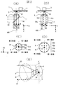
- FIG. 3 is a diagram illustrating a part of the light source device according to the first embodiment.
- FIG. 5 is a diagram illustrating a part of a light source device according to a second embodiment.
- 1 is a schematic configuration diagram of an optical system of a projection display apparatus. The figure which shows a part of light source device of a prior art.
- Patent Document 1 the prior art (Patent Document 1) and its problems will be described.
- FIG. 4A and 4B are diagrams showing a part of a conventional light source device.
- FIG. 4A is a configuration explanatory view
- FIG. 4B is a diagram showing an incident angle of excitation light to a phosphor
- FIG. (D) is a configuration explanatory view showing the principle of incident excitation light to the excitation light source.
- a local right-handed rectangular coordinate system is introduced.
- the traveling direction of the excitation light after being reflected by the reflecting mirror is the Z axis
- the axis parallel to the paper surface in the plane perpendicular to the Z axis is the X axis
- the axis from the back to the front surface is the Y axis.
- the excitation light 50 emitted from the excitation light source group 5 including a plurality of excitation light sources composed of solid state light emitting elements becomes substantially parallel light by the collimating lens group 6, is reflected by the reflection mirror 8, and is applied to the dichroic mirror 7.
- the dichroic mirror 7 has a characteristic of transmitting the wavelength range of excitation light and reflecting the wavelength range of fluorescent light. Therefore, the excitation light 50 passes through the dichroic mirror 7, passes through the condenser lens 4, and then enters the disk 1 on which the phosphor 3 is applied.
- the curvature of the condenser lens 4 is set so that the incident parallel light is condensed on the excitation light irradiation region 30 of the disk 1.
- the disk 1 is a circular base material whose rotation is controllable with the rotation element 2 as a central axis.
- a metal is desirable as the base material.
- the phosphor 3 on the disk 1 excited by the excitation light 50 emits the fluorescence light 60 in all directions, but the fluorescence light 60 emitted in the direction of the base material is reflected by the metal surface. Accordingly, all the fluorescent light 60 is emitted in the direction of the condenser lens 4.
- the fluorescent light 60 transmitted through the condenser lens 4 becomes substantially parallel light, is reflected by the dichroic mirror 7 and enters the illumination optical system side (not shown).
- the distance between the phosphor 3 and the condensing lens 4 is large in the drawing, in practice, almost all the fluorescent light 60 is captured by the condensing lens 4 by arranging the condensing lens 4 in the vicinity of the phosphor 3. it can.
- the optical axis 100 is an axis that passes through the excitation light irradiation region 30 and is parallel to the Z axis
- the excitation light 50 emitted from the excitation light source group 5 is symmetrical with respect to the optical axis 100 on the phosphor 3. Is incident on the excitation light irradiation region 30.
- the incident angles of the excitation lights 50a, 50b, 50c generated from the excitation light sources 5a, 5b, 5c to the excitation light irradiation region 30 with respect to the optical axis 100 are ⁇ a, ⁇ b, ⁇ c, respectively. Then, since the excitation light enters the optical axis 100 symmetrically, Equation 1 is established.
- the non-converted excitation light 51c that is not converted into fluorescent light by the phosphor 3 is incident on the excitation light source 5a, resulting in a decrease in the output of the excitation light source 5a and a decrease in lifetime. (Not shown).
- the excitation light 50b emitted from the excitation light source 5b in the excitation light source group 5 enters the excitation light irradiation region 30 through the optical path described above.
- a part of the excitation light 50b is not converted into fluorescent light, but is reflected by the phosphor 3 as non-converted excitation light 51b.
- the non-converted excitation light 51b of the excitation light source 5b causes a decrease in output or a decrease in life of the excitation light source 5b.
- non-converted excitation light out of excitation light emitted from a plurality of excitation light source groups is incident on the excitation light source group, resulting in a temperature rise of the light emitting element, and the output of the excitation light source. It has a problem that it leads to a reduction and a life reduction.
- FIG. 1 is a diagram illustrating a part of the light source device according to the first embodiment.
- FIG. 1A is a configuration explanatory diagram
- FIGS. 1B, 1C, and 1D are configuration explanatory diagrams showing measures for improving the incident excitation light to the excitation light source.
- the definition of the local right-handed rectangular coordinate system is the same as in FIG.
- the point that the excitation light emitted from the excitation light source group 5 is converted into fluorescent light and incident on the illumination optical system side is the same as in the description of FIG.
- the excitation light source group 5 is arranged so that the excitation light 50 emitted from the excitation light source group 5 enters the excitation light irradiation region 30 on the phosphor 3 asymmetrically with respect to the optical axis 100. ing.
- Equation 2 In FIG. 1B, in the excitation light source group 5, the excitation light 50a emitted from the excitation light source 5a enters the excitation light irradiation region 30 through the same optical path as described in FIG. Among them, a part of the excitation light is not converted into fluorescent light but reflected by the phosphor 3.
- the non-converted excitation light 51a that is not converted into fluorescent light is specularly reflected mainly in a direction symmetrical to the optical axis 100, becomes substantially parallel to the optical axis 100 by the condenser lens 4, passes through the dichroic mirror 7, and is reflected by the reflecting mirror. Incident on the 8th side.
- the excitation light source group 5 is arranged so that the optical path of the excitation light 50 to the phosphor 3 and the optical path of the non-converted excitation light 51 from the phosphor 3 are asymmetric via the optical axis 100. Accordingly, the non-converted excitation light 51a passes between the reflection mirrors 8b and 8c, or passes between the excitation light sources 5b and 5c even if it is reflected by the reflection mirror 8; Not incident.
- the excitation light 50b emitted from the excitation light source 5b in the excitation light source group 5 is incident on the excitation light irradiation region 30 through the same optical path as described above. Among them, a part of the excitation light is not converted into fluorescent light but reflected by the phosphor 3.
- the non-converted excitation light 51b that is not converted into fluorescent light is specularly reflected mainly in a direction symmetrical to the optical axis 100, becomes substantially parallel to the optical axis 100 by the condenser lens 4, passes through the dichroic mirror 7, and is reflected by the reflecting mirror. Incident on the 8th side.
- the non-converted excitation light 51b passes between the reflection mirrors 8a and 8b, or passes between the excitation light sources 5a and 5b even when reflected by the reflection mirror 8, so that the excitation light source It does not enter Group 5.
- the excitation light 50c emitted from the excitation light source 5c in the excitation light source group 5 enters the excitation light irradiation region 30 through the same optical path as described above.
- a part of the excitation light is not converted into fluorescent light but is reflected by the phosphor 3 as non-converted excitation light 51c.
- the non-converted excitation light 51c is specularly reflected mainly in a direction symmetrical to the optical axis 100, becomes substantially parallel to the optical axis 100 by the condenser lens 4, passes through the dichroic mirror 7, and enters the reflecting mirror 8 side.
- the non-converted excitation light 51c passes through the outside of the reflection mirror 8a or passes through the outside of the excitation light source 5a even if it is reflected by the reflection mirror 8; Not incident.
- the excitation lights 50a, 50b, and 50c generated from the excitation light sources 5a, 5b, and 5c the non-converted excitation lights 51a, 51b, and 51c that are not converted into fluorescent light are incident on the excitation light source group 5. Therefore, the output and life of the excitation light source group 5 can be improved.
- FIG. 2 is a diagram illustrating a part of the light source device according to the second embodiment.
- a local right-handed rectangular coordinate system is introduced.
- the optical axis 100 is the Z axis
- the axis parallel to the paper surface in the plane orthogonal to the Z axis is the X axis
- the axis from the back of the paper surface to the front is the Y axis (however, FIG. For B)
- the axis from the back of the paper to the front is the X axis
- FIGS. 2C and 2D the axis from the back of the paper to the front is the Z axis).
- the excitation light source group 5 includes three columns of excitation light sources in the X-axis direction and two rows in the Y-axis direction.
- the arrangement of the excitation light source groups in the X axis direction is symmetric with respect to the optical axis 100, and the arrangement of the excitation light source groups in the Y axis direction is asymmetric with respect to the optical axis 100.
- the excitation light 50 emitted from the excitation light source group 5 enters the excitation light irradiation region 30 on the phosphor 3 through the same optical path as described in FIG.
- the reflection mirror 8 between the collimating lens group 6 and the dichroic mirror 7 is omitted.
- a part of the excitation light 50 is not converted into fluorescent light, but is reflected by the phosphor 3 as non-converted excitation light.
- the excitation light 50 u emitted from the excitation light source group 5 u the non-converted excitation light 51 u that is not converted into fluorescence light in the phosphor 3 is specularly reflected mainly in a direction symmetrical to the optical axis 100.
- the condenser lens 4 is substantially parallel to the optical axis 100 and passes through the dichroic mirror 7.
- the excitation light source group 5 is arranged at a position where the incident light of the excitation light 50 to the phosphor 3 is asymmetric with respect to the optical axis 100 with respect to the Y-axis direction. It passes outside the group 5d.
- the non-converted excitation light 51d that is not converted into fluorescence light in the phosphor 3 is specularly reflected mainly in a direction symmetrical to the optical axis 100, and the condenser lens 4 Thus, it is substantially parallel to the optical axis 100 and passes through the dichroic mirror 7. Since the excitation light source group 5 is disposed at a position where the incident light of the excitation light 50 to the phosphor 3 is asymmetric with respect to the optical axis 100 with respect to the Y-axis direction, the non-converted excitation light 51d is the excitation light source group. It passes between 5u and the excitation light source group 5d.
- the excitation light source group 5 output and life can be improved.
- FIG. 2C is a projection view of the XY section viewed from the direction of the optical axis 100 (Z-axis direction). Since the incident light to the phosphor 3 of the excitation light 50 emitted from the excitation light source group 5 is asymmetric in the Y-axis direction around the excitation light irradiation region 30, the non-converted excitation light 51 is included in the excitation light source group 5. Not incident. Further, since the excitation light 50 enters the excitation light irradiation region 30 from all four quadrants centered on the excitation light irradiation region 30, the condenser lens 4 can be suppressed to a compact size.
- FIG. 2D shows an example in which the excitation light 50 is incident from two quadrants (first quadrant and second quadrant) among the four quadrants centered on the excitation light irradiation region 30. Since the incident light to the phosphor 3 of the excitation light 50 is asymmetric in the Y-axis direction with the excitation light irradiation region 30 as the center, it is possible to prevent the non-converted excitation light 51 from entering the excitation light source group 5. Since the excitation light 50 enters the excitation light irradiation region 30 from a position away from the excitation light irradiation region 30 in the Y-axis direction, the condensing lens 4 is increased in size. Therefore, it is desirable that the excitation light 50 is incident from all four quadrants centered on the excitation light irradiation region 30.
- conditions for preventing the non-converted excitation light 51 from entering the excitation light source group 5 are represented using a polar coordinate system centered on the excitation light irradiation region 30.
- the elevation angle from the Z-axis direction is ⁇
- the azimuth angle in the XY coordinates is ⁇ .
- the excitation light 50 is incident from the Z-axis direction and is incident on the excitation light irradiation region 30 at the elevation angle ⁇ and the azimuth angle ⁇ by the condenser lens 4
- the non-converted excitation light 51 has the elevation angle ⁇ and the azimuth angle. Ejection with an injection angle of ⁇ + 180 °.
- Equation 4 That is, either the elevation angle or the azimuth angle is shifted, and the excitation light 50 may be incident on the excitation light irradiation region 30 so that the incident / exit lights do not overlap each other. Since the distance from the excitation light source 5 to the excitation light irradiation region 30 is sufficiently large, the incidence of the non-converted excitation light 51 on the excitation light source group 5 can be prevented by shifting each excitation light incident angle by 2 degrees or more. . In other words, it is sufficient that there is no pair of excitation light that satisfies Equation 5.
- FIG. 3A is a schematic configuration diagram of an optical system of a projection display apparatus including the light source device of FIG.
- the blue excitation light emitted from the excitation light source group 5 becomes substantially parallel by the collimating lens group 6, is reflected by the reflection mirror 8, and enters the dichroic mirror 7.
- the dichroic mirror 7 has a characteristic of transmitting blue light and reflecting green light. Accordingly, the blue excitation light passes through the dichroic mirror 7, is condensed by the condenser lens 4, and is condensed on the disk 1.
- the curvature of the condenser lens 4 is set so that the incident parallel light is condensed at one place of the disk 1.
- the disk 1 is a circular base material coated with a green phosphor 3 and capable of rotation control with the rotating element 2 as a central axis.
- the green light transmitted through the condenser lens 4 is substantially parallel to the optical axis 100 and reflected by the dichroic mirror 7.
- the light passes through the condenser lens 9 and enters the dichroic mirror 10.
- the dichroic mirror 10 has a characteristic of transmitting green light and reflecting red light and blue light. Accordingly, the green light passes through the dichroic mirror 10 and enters the multiple reflection element 17.
- the condensing lens 9 is set to have a curvature that condenses on the incident aperture of the multiple reflection element 17, the incident aperture surface of the multiple reflection element 17 is similar to the irradiation shape of the excitation light irradiation region 30. A shape is formed.
- the light source 11 is a red light source.
- the red light emitted from the light source 11 is collimated by the collimating lens 12 and enters the dichroic mirror 15.
- the dichroic mirror 15 has a characteristic of transmitting red light and reflecting blue light. Accordingly, the red light passes through the dichroic mirror 15, passes through the condenser lens 16, and enters the dichroic mirror 10.
- the light source 13 is a blue light source.
- the blue light emitted from the light source 13 becomes parallel by the collimating lens 14 and enters the dichroic mirror 15.
- the dichroic mirror 15 has a characteristic of transmitting red light and reflecting blue light. Accordingly, the blue light is reflected by the dichroic mirror 15, passes through the condenser lens 16, and enters the dichroic mirror 10.
- the dichroic mirror 10 has a characteristic of transmitting green light and reflecting red light and blue light. Therefore, the red light and blue light incident on the dichroic mirror 10 are reflected by the dichroic mirror 10 and incident on the multiple reflection element 17.
- the condensing lens 16 is set to have a curvature that condenses on the incident aperture of the multiple reflection element 17, the incident aperture surface of the multiple reflection element 17 is similar to the light emission shapes of the light sources 11 and 13. A shape is formed. Further, the arrangement position of the light source 11 and the light source 13 may be changed by changing the characteristics of the dichroic mirror 15.
- the red light, the green light, and the blue light incident on the multiple reflection element 17 are reflected by the multiple reflection element 17 a plurality of times, and become light having a uniform illuminance distribution on the exit aperture surface of the multiple reflection element 17.
- the shape of the exit aperture surface of the multiple reflection element 17 is substantially similar to that of the image display element 20.
- the condenser lens 18 is set to a curvature that enlarges and forms an image formed on the exit aperture surface of the multiple reflection element 17 on the video display element 20. Accordingly, red light, green light, and blue light emitted from the exit aperture surface of the multiple reflection element 17 are transmitted through the condenser lens 18, reflected by the reflection mirror 19, and then irradiated onto the image display element 20 with a uniform illuminance distribution. Is done.
- the excitation light source group 5, the light source 11, and the light source 13 are solid-state light emitting elements with a fast response speed, and can be time-division controlled. Accordingly, each color light is modulated by the video display element 20 in a time division manner for each color light. Each color light reflected by the image display element 20 enters the projection lens 21 and is projected on a screen (not shown).
- FIG. 3B is a schematic configuration diagram of an optical system of a projection-type image display device including a light source device having a form different from that in FIG.
- the blue excitation light emitted from the excitation light source group 5 becomes substantially parallel by the collimating lens group 6, is reflected by the reflection mirror 8, and enters the dichroic mirror 70.
- the dichroic mirror 70 has a characteristic of reflecting blue light and transmitting green light. Therefore, the blue excitation light is reflected by the dichroic mirror 70, collected by the condenser lens 4, and collected on the disk 1.
- the curvature of the condenser lens 4 is set so that the incident parallel light is condensed at one place of the disk 1.
- the disk 1 is a circular base material coated with a green phosphor 3 and capable of rotation control with the rotating element 2 as a central axis.
- the green light transmitted through the condenser lens 4 is substantially parallel to the optical axis 100 and transmitted through the dichroic mirror 70.
- the light passes through the condenser lens 9 and enters the dichroic mirror 10.
- the dichroic mirror 10 has a characteristic of transmitting green light and reflecting red light and blue light. Accordingly, the green light passes through the dichroic mirror 10 and enters the multiple reflection element 17.
- the condensing lens 9 is set to have a curvature that condenses on the incident aperture of the multiple reflection element 17, the incident aperture surface of the multiple reflection element 17 is similar to the irradiation shape of the excitation light irradiation region 30. A shape is formed.
- the subsequent optical system is the same as that shown in FIG.
- the image display element in the present embodiment may be a DMD (Digital Mirror Device) element or a liquid crystal image display element (liquid crystal panel).
- DMD Digital Mirror Device
- liquid crystal image display element liquid crystal panel
- excitation light sources In this embodiment, an example in which a plurality of excitation light sources exist is shown. However, when the excitation light emitted from the excitation light source enters the excitation light irradiation region and is reflected without being converted into fluorescent light, the non-conversion excitation is performed. As long as light is arranged so as not to enter the excitation light source, the number of excitation light sources may be one.
Landscapes
- Physics & Mathematics (AREA)
- Engineering & Computer Science (AREA)
- Spectroscopy & Molecular Physics (AREA)
- General Physics & Mathematics (AREA)
- General Engineering & Computer Science (AREA)
- Multimedia (AREA)
- Signal Processing (AREA)
- Optics & Photonics (AREA)
- Projection Apparatus (AREA)
- Non-Portable Lighting Devices Or Systems Thereof (AREA)
- Fastening Of Light Sources Or Lamp Holders (AREA)
- Video Image Reproduction Devices For Color Tv Systems (AREA)
- Investigating, Analyzing Materials By Fluorescence Or Luminescence (AREA)
- Microscoopes, Condenser (AREA)
Abstract
励起光により蛍光体を励起して蛍光光を発光させる光源を使用する場合、励起光の励起光源への入射を低減することにより、励起光の出力を増大させ、長寿命化を実現した光源装置を提供する。 当該光源装置は、励起光を発光する複数の励起光源(5a、5b、5c)と、励起光を蛍光光に変化させる蛍光体(3)と、ダイクロイックミラー(7)と、励起光を蛍光体(3)上の励起光照射領域に集光させる集光レンズ(4)と、を備え、複数の励起光源(5a、5b、5c)は、当該複数の励起光源(5a、5b、5c)の各々から出射された各々の励起光が、集光レンズ(4)の中心に対して非対称に入射するよう配置される。
Description
本発明は、投写型映像表示装置に用いられる光源装置に関する。
当該技術分野において、固体光源から射出する可視光を高効率で発光する光源装置が提案されている(特許文献1参照)。特許文献1では、複数の青色励起光源から出射した光を、回転制御可能な円形状の基材に配置された蛍光体に照射し、高効率な蛍光光を発光させている。
特許文献1によれば、蛍光体に入射した励起光の内、蛍光光に変換されなかった非変換励起光が照明光学系側に入射しないことは記載されているが、非変換励起光が励起光源に入射し、励起光源の出力低下、寿命低下を招く点については、考慮されていない。
そこで、本発明の目的は、励起光源の出力と寿命を改善した光源装置を提供することにある。
上記課題を解決するため、本発明の望ましい態様の一つは次の通りである。当該光源装置は、励起光を発光する複数の励起光源と、励起光を蛍光光に変化させる蛍光体と、を備え、複数の励起光源は、当該複数の励起光源の各々から出射された各々の励起光が、蛍光体上の励起光照射領域に対して非対称に入射するよう配置される。
本発明によれば、励起光源の出力と寿命を改善した光源装置を提供することができる。
以下、本実施例について、図を参照しながら説明する。尚、各図において、同一部分には同一符号を付して、一度説明したものについては、その説明を省略する。まず、本実施例と従来技術の差異を分かりやすくするため、従来技術(特許文献1)とその課題について説明する。
図4は、従来技術の光源装置の一部を示す図であり、図4(A)は構成説明図、図4(B)は蛍光体への励起光入射角度を示す図、図4(C)(D)は、課題となる励起光の励起光源への入射の原理を示す構成説明図である。ここで、ローカル右手直角座標系を導入しておく。図4において、反射ミラーで反射後の励起光の進行方向をZ軸、Z軸に直交する面内で紙面に平行な軸をX軸、紙面裏から表に向かう軸をY軸とする。
図4(A)において、固体発光素子からなる励起光源を複数含む励起光源群5から射出した励起光50は、コリメートレンズ群6により略平行光となり、反射ミラー8で反射し、ダイクロイックミラー7に入射する。ダイクロイックミラー7は励起光の波長域を透過し、蛍光光の波長域を反射する特性を持つ。そこで、励起光50は、ダイクロイックミラー7を透過し、集光レンズ4を透過後、蛍光体3が塗布された円盤1に入射する。集光レンズ4の曲率は、入射した平行光が円盤1の励起光照射領域30に集光するように設定されている。
円盤1は、回転素子2を中心軸とする回転制御可能な円形状の基材である。蛍光体から発生する熱を逃がすために、基材としては金属が望ましい。この場合、励起光50により励起された円盤1上の蛍光体3は、全方位に蛍光光60を射出するが、基材の方向に射出した蛍光光60は、金属面で反射する。従って、全ての蛍光光60が集光レンズ4の方向に射出される。その内、集光レンズ4を透過した蛍光光60は、略平行光となり、ダイクロイックミラー7で反射して、図示されない照明光学系側に入射する。図面上では、蛍光体3と集光レンズ4の間隔が大きいが、実際は、集光レンズ4を蛍光体3の近傍に配置することで、ほぼ全ての蛍光光60を、集光レンズ4で捕獲できる。ここで、励起光照射領域30を通過し、Z軸に平行な軸を光軸100とすると、励起光源群5から射出した励起光50は、光軸100に対して対称に、蛍光体3上の励起光照射領域30に入射する。
図4(B)において、各励起光源5a、5b、5cから発生した各励起光50a、50b、50cの、光軸100に対する励起光照射領域30への入射角を各々、θa、θb、θcとすると、励起光は光軸100に対称に入射するため、数1が成り立つ。
θa=θc、θb=0・・・(数1)
図4(C)において、励起光源群5の内、励起光源5aから射出した励起光50aは前述した光路で励起光照射領域30に入射角θaで入射する。励起光50aの一部は蛍光光に変換されず、非変換励起光51aとして、蛍光体3で主に光軸100と対称な方向(出射角θa)に正反射する。数1より、θa=θcのため、非変換励起光51aは、励起光50cの光路上を逆方向に進行し、励起光源5cに入射する。即ち、励起光源5aに起因する非変換励起光51aにより、励起光源5cの出力低下や寿命低下が発生する。
図4(C)において、励起光源群5の内、励起光源5aから射出した励起光50aは前述した光路で励起光照射領域30に入射角θaで入射する。励起光50aの一部は蛍光光に変換されず、非変換励起光51aとして、蛍光体3で主に光軸100と対称な方向(出射角θa)に正反射する。数1より、θa=θcのため、非変換励起光51aは、励起光50cの光路上を逆方向に進行し、励起光源5cに入射する。即ち、励起光源5aに起因する非変換励起光51aにより、励起光源5cの出力低下や寿命低下が発生する。
同様に、励起光源5cから射出した励起光50cのうち、蛍光体3で蛍光光に変換されない非変換励起光51cは、励起光源5aに入射し、励起光源5aの出力低下や寿命低下が発生する(図示せず)。
図4(D)において、励起光源群5の内、励起光源5bから射出した励起光50bは前述した光路で励起光照射領域30に入射する。励起光50bの一部は蛍光光に変換されず、非変換励起光51bとして蛍光体3で反射する。励起光50bの励起光照射領域30への入射角はθb=0のため、非変換励起光51bは、光軸100と同一軸方向に正反射し、励起光50bの光路上を逆方向に進行し、励起光源5bに入射する。即ち、励起光源5bの非変換励起光51bにより、励起光源5bの出力低下や寿命低下が発生する。
以上のように、従来技術においては、複数の励起光源群から射出した励起光のうちの非変換励起光が、励起光源群に入射し、発光素子の温度上昇等が発生し、励起光源の出力低下や寿命低下を招く、という課題を有する。
次に、実施例1について説明する。図1は、実施例1の光源装置の一部を示す図である。図1(A)は構成説明図、図1(B)(C)(D)は、課題となる励起光の励起光源への入射に対する、改善策を示す構成説明図である。ローカル右手直角座標系の定義は、図4と同一である。
図1(A)において、励起光源群5から射出した励起光が蛍光光に変換され、照明光学系側に入射する点については図4の説明と同様である。但し、本実施例においては、励起光源群5から射出した励起光50が光軸100に対して非対称に蛍光体3上の励起光照射領域30に入射するように、励起光源群5が配置されている。即ち、各励起光源5a、5b、5cから発生した各励起光50a、50b、50cの、光軸100に対する励起光照射領域30への入射角を各々、θa、θb、θcとすると、数2が成り立つ。
θa≠θb≠θc、θc≠θa(θa≠0、θb≠0、θc≠0)・・・(数2)
図1(B)において、励起光源群5の内、励起光源5aから射出した励起光50aは図4において説明したのと同様の光路で励起光照射領域30に入射する。そのうち、一部の励起光は蛍光光に変換されず、蛍光体3で反射する。蛍光光に変換されない非変換励起光51aは、主に光軸100と対称な方向に正反射し、集光レンズ4で光軸100に対して略平行となり、ダイクロイックミラー7を透過し、反射ミラー8側に入射する。励起光源群5は、励起光50の蛍光体3までの光路と蛍光体3からの非変換励起光51の光路が光軸100を介して非対称となるように配置されている。従って、非変換励起光51aは、反射ミラー8b、8cの間を通過するか、もしくは、反射ミラー8で反射しても、励起光源5b、5cの間を通過するため、励起光源群5へは入射しない。
図1(B)において、励起光源群5の内、励起光源5aから射出した励起光50aは図4において説明したのと同様の光路で励起光照射領域30に入射する。そのうち、一部の励起光は蛍光光に変換されず、蛍光体3で反射する。蛍光光に変換されない非変換励起光51aは、主に光軸100と対称な方向に正反射し、集光レンズ4で光軸100に対して略平行となり、ダイクロイックミラー7を透過し、反射ミラー8側に入射する。励起光源群5は、励起光50の蛍光体3までの光路と蛍光体3からの非変換励起光51の光路が光軸100を介して非対称となるように配置されている。従って、非変換励起光51aは、反射ミラー8b、8cの間を通過するか、もしくは、反射ミラー8で反射しても、励起光源5b、5cの間を通過するため、励起光源群5へは入射しない。
図1(C)において、励起光源群5の内、励起光源5bから射出した励起光50bは前述したのと同様の光路で励起光照射領域30に入射する。そのうち、一部の励起光は蛍光光に変換されず、蛍光体3で反射する。蛍光光に変換されない非変換励起光51bは、主に光軸100と対称な方向に正反射し、集光レンズ4で光軸100に対して略平行となり、ダイクロイックミラー7を透過し、反射ミラー8側に入射する。上記同様の理由で、非変換励起光51bは、反射ミラー8a、8bの間を通過するか、もしくは、反射ミラー8で反射しても、励起光源5a、5bの間を通過するため、励起光源群5へは入射しない。
図1(D)において、励起光源群5の内、励起光源5cから射出した励起光50cは前述したのと同様の光路で励起光照射領域30に入射する。そのうち、一部の励起光は蛍光光に変換されず、非変換励起光51cとして蛍光体3で反射する。非変換励起光51cは、主に光軸100と対称な方向に正反射し、集光レンズ4で光軸100に対して略平行となり、ダイクロイックミラー7を透過し、反射ミラー8側に入射する。上記同様の理由で、非変換励起光51cは、反射ミラー8aの外側を通過するか、もしくは、反射ミラー8で反射しても、励起光源5aの外側を通過するため、励起光源群5へは入射しない。
以上のように、各励起光源5a、5b、5cから発生した各励起光50a、50b、50cの内、蛍光光に変換されない各非変換励起光51a、51b、51cは、励起光源群5へ入射しないため、励起光源群5の出力や寿命を改善することができる。
次に、実施例2について説明する。図2は、実施例2の光源装置の一部を示す図である。ここで、ローカル右手直角座標系を導入しておく。図2(A)において、光軸100をZ軸として、Z軸に直交する面内で紙面に平行な軸をX軸、紙面裏から表に向かう軸をY軸とする(但し、図2(B)については紙面裏から表に向かう軸がX軸、図2(C)(D)については紙面裏から表に向かう軸がZ軸となる)。
図2において、励起光源群5はX軸方向に3列、Y軸方向に2行の励起光源が配置されている。X軸方向の励起光源群の配列は光軸100に対称、Y軸方向の励起光源群の配列は光軸100に非対称とする。図2(A)において、励起光源群5から射出した励起光50は、図1において説明したのと同様の光路で、蛍光体3上の励起光照射領域30に入射し、蛍光光60に変換され、図示しない照明光学系に入射する(簡略化のため、コリメートレンズ群6とダイクロイックミラー7の間の反射ミラー8は省略)。そのうち、励起光50の一部が蛍光光に変換されず、非変換励起光として、蛍光体3で反射する。
図2(B)において、励起光源群5uから射出した励起光50uの内、蛍光体3において、蛍光光に変換されない非変換励起光51uは、主に光軸100と対称な方向に正反射し、集光レンズ4で光軸100に対して略平行となり、ダイクロイックミラー7を透過する。励起光源群5は、励起光50の蛍光体3への入射光が光軸100とは、Y軸方向に対して非対称となる位置に配置されているため、非変換励起光51uは、励起光源群5dの外側を通過する。
又、励起光源群5dから射出した励起光50dの内、蛍光体3において、蛍光光に変換されない非変換励起光51dは、主に光軸100と対称な方向に正反射し、集光レンズ4で光軸100に対して略平行となり、ダイクロイックミラー7を透過する。励起光源群5は、励起光50の蛍光体3への入射光が光軸100とはY軸方向に対して非対称となる位置に配置されているため、非変換励起光51dは、励起光源群5uと励起光源群5dの間を通過する。
以上のように、各励起光源5u、5dから発生した各励起光50u、50dの内、蛍光光に変換されない各非変換励起光51u、51dは、励起光源群5へ入射しないため、励起光源群5の出力や寿命を改善することができる。
図2(C)は、光軸100の方向(Z軸方向)から、XY断面を見た投影図である。励起光源群5から射出した励起光50の蛍光体3への入射光が、励起光照射領域30を中心として、Y軸方向に非対称であるため、非変換励起光51は励起光源群5には入射しない。又、励起光50は励起光照射領域30を中心とする4つの象限全ての領域から、励起光照射領域30へ入射するため、集光レンズ4をコンパクトなサイズに抑えることができる。
図2(D)は、励起光50を、励起光照射領域30を中心とする4つの象限の内、2つの象限(第1象限、第2象限)から入射した例である。励起光50の蛍光体3への入射光が、励起光照射領域30を中心として、Y軸方向に非対称であるため、非変換励起光51の励起光源群5への入射は防ぐことができるが、励起光照射領域30からY軸方向に離れた位置より励起光50が励起光照射領域30に入射するため、集光レンズ4の大型化を招いてしまう。従って、励起光50は励起光照射領域30を中心とする4つの象限全ての象限より入射することが望ましい。
図2(E)において、非変換励起光51の励起光源群5への入射を防ぐための条件を、励起光照射領域30を中心とする極座標系を用いて表す。Z軸方向からの仰角をθ、XY座標内での方位角をφとする。励起光50がZ軸方向より入射し、集光レンズ4で、励起光照射領域30へ、仰角θ、方位角φの入射角で入射する場合、非変換励起光51は、仰角θ、方位角φ+180°の射出角で射出する。従って、任意の励起光の入射角を仰角θm、方位角φmとし、別の任意の励起光の入射角を仰角θn、方位角φnとすると、非変換励起光51の励起光源群5への入射を防ぐための条件として、数3、又は、数4が成り立つ。
θn≠θm(θm≠0、θn≠0) ・・・(数3)
φn≠φm+180°(θm≠0、θn≠0)・・・(数4)
即ち、仰角又は方位角のどちらかをずらして、お互いの入出射光が重ならないように、励起光50を励起光照射領域30に入射させればよい。励起光源5から励起光照射領域30までの距離は充分離れているので、各々の励起光入射角を2度以上ずらせば、非変換励起光51の励起光源群5への入射を防ぐことができる。即ち、数5が成立する励起光のペアを、1つも有さなければよい。
φn≠φm+180°(θm≠0、θn≠0)・・・(数4)
即ち、仰角又は方位角のどちらかをずらして、お互いの入出射光が重ならないように、励起光50を励起光照射領域30に入射させればよい。励起光源5から励起光照射領域30までの距離は充分離れているので、各々の励起光入射角を2度以上ずらせば、非変換励起光51の励起光源群5への入射を防ぐことができる。即ち、数5が成立する励起光のペアを、1つも有さなければよい。
θm-2°≦θn≦θm+2° かつ φm+178°≦φm≦φm+182°・・・(数5)
次に、投写型映像表示装置の光学系について説明する。図3(A)は、図1の光源装置を含む投射型映像表示装置の、光学系の概略構成図である。励起光源群5から射出した青色励起光は、コリメートレンズ群6により略平行となり、反射ミラー8で反射し、ダイクロイックミラー7に入射する。ダイクロイックミラー7は青色光を透過し、緑色光を反射する特性である。従って、青色励起光はダイクロイックミラー7を透過し、集光レンズ4で集光し、円盤1に集光する。
次に、投写型映像表示装置の光学系について説明する。図3(A)は、図1の光源装置を含む投射型映像表示装置の、光学系の概略構成図である。励起光源群5から射出した青色励起光は、コリメートレンズ群6により略平行となり、反射ミラー8で反射し、ダイクロイックミラー7に入射する。ダイクロイックミラー7は青色光を透過し、緑色光を反射する特性である。従って、青色励起光はダイクロイックミラー7を透過し、集光レンズ4で集光し、円盤1に集光する。
集光レンズ4の曲率は、入射した平行光が円盤1の1箇所に集光するように設定されている。円盤1は、緑色蛍光体3が塗布され、回転素子2を中心軸とする回転制御可能な円形状の基材である。緑色蛍光体3が励起されることにより生じ、全方位に発光した緑色蛍光光の内、集光レンズ4を透過した緑色光は、光軸100に略平行となり、ダイクロイックミラー7で反射して、集光レンズ9を透過し、ダイクロイックミラー10に入射する。ダイクロイックミラー10は緑色光を透過し、赤色光、青色光を反射する特性である。従って、緑色光はダイクロイックミラー10を透過し、多重反射素子17に入射する。集光レンズ9は、多重反射素子17の入射開口部に集光するような曲率に設定されているため、多重反射素子17の入射開口面には、励起光照射領域30の照射形状と相似な形状が形成される。
光源11は赤色光源である。光源11を射出した赤色光は、コリメートレンズ12で平行となり、ダイクロイックミラー15に入射する。ダイクロイックミラー15は赤色光を透過し、青色光を反射する特性である。従って、赤色光はダイクロイックミラー15を透過して、集光レンズ16を透過し、ダイクロイックミラー10に入射する。
一方、光源13は青色光源である。光源13を射出した青色光は、コリメートレンズ14で平行となり、ダイクロイックミラー15に入射する。ダイクロイックミラー15は赤色光を透過し、青色光を反射する特性である。従って、青色光はダイクロイックミラー15で反射して、集光レンズ16を透過し、ダイクロイックミラー10に入射する。ダイクロイックミラー10は緑色光を透過し、赤色光、青色光を反射する特性である。従って、ダイクロイックミラー10に入射した赤色光と青色光は、ダイクロイックミラー10で反射し、多重反射素子17に入射する。
集光レンズ16は、多重反射素子17の入射開口部に集光するような曲率に設定されているため、多重反射素子17の入射開口面には、光源11と光源13の発光形状と相似な形状が形成される。又、ダイクロイックミラー15の特性を変更して、光源11と光源13の配置位置を変えても構わない。
多重反射素子17に入射した、赤色光、緑色光、青色光は、多重反射素子17で複数回反射し、多重反射素子17の出射開口面では、均一照度分布を有する光となる。多重反射素子17の出射開口面の形状は、映像表示素子20と略相似な形状である。集光レンズ18は、多重反射素子17の出射開口面に形成された像を、映像表示素子20上に拡大して結像する曲率に設定されている。従って、多重反射素子17の出射開口面から射出した赤色光、緑色光、青色光は、集光レンズ18を透過し、反射ミラー19で反射後、映像表示素子20上に均一な照度分布で照射される。
励起光源群5、光源11、光源13は応答速度の速い固体発光素子であり、時分割制御が可能である。従って、各色光は、映像表示素子20により、各色光毎に時分割で変調される。映像表示素子20で反射された各色光は、投写レンズ21に入射し、図示していないスクリーン上に投影される。
図3(B)は、図3(A)とは異なる形態の光源装置を含む投射型映像表示装置の、光学系の概略構成図である。励起光源群5から射出した青色励起光は、コリメートレンズ群6により略平行となり、反射ミラー8で反射し、ダイクロイックミラー70に入射する。ダイクロイックミラー70は青色光を反射し、緑色光を透過する特性である。従って、青色励起光はダイクロイックミラー70を反射し、集光レンズ4で集光し、円盤1に集光する。
集光レンズ4の曲率は、入射した平行光が円盤1の1箇所に集光するように設定されている。円盤1は、緑色蛍光体3が塗布され、回転素子2を中心軸とする回転制御可能な円形状の基材である。緑色蛍光体3が励起されることにより生じ、全方位に発光した緑色蛍光光の内、集光レンズ4を透過した緑色光は、光軸100に略平行となり、ダイクロイックミラー70を透過して、集光レンズ9を透過し、ダイクロイックミラー10に入射する。ダイクロイックミラー10は緑色光を透過し、赤色光、青色光を反射する特性である。従って、緑色光はダイクロイックミラー10を透過し、多重反射素子17に入射する。集光レンズ9は、多重反射素子17の入射開口部に集光するような曲率に設定されているため、多重反射素子17の入射開口面には、励起光照射領域30の照射形状と相似な形状が形成される。以降の光学系は、図3(A)と同一であり、省略する。
本実施例における映像表示素子は、DMD(Digital Mirror Device)素子でもよいし、液晶型映像表示素子(液晶パネル)でもよい。
又、本実施例では、蛍光体3を回転させる例を示した。これは、蛍光体を分散して固めるバインダとして、有機のシリコン樹脂等が用いられているため、温度によるバーニングを防ぐ必要があるからである。しかし、無機のバインダを使用するなどして、蛍光体寿命が確保できるのであれば、蛍光体を回転させなくてもよい。
又、本実施例では、励起光源が複数存在する例を示したが、当該励起光源から出射した励起光が励起光照射領域に入射し蛍光光に変換されずに反射した場合、当該非変換励起光が当該励起光源に入射しないように配置されていれば、励起光源は1つであってもよい。
1…円盤、2…回転素子、3…蛍光体、4…集光レンズ、5…励起光源群、6…コリメートレンズ群、7…ダイクロイックミラー、8…反射ミラー、30…励起光照射領域、50…励起光、51…非変換励起光、60…蛍光光、70…ダイクロイックミラー。
Claims (9)
- 励起光を発光する複数の励起光源と、
前記励起光を蛍光光に変化させる蛍光体と、
前記励起光を透過し前記蛍光光を反射するダイクロイックミラーと、
前記ダイクロイックミラーを透過した励起光を前記蛍光体上の励起光照射領域に集光させる集光レンズと、を備え、
前記複数の励起光源は、当該複数の励起光源の各々から出射された各々の励起光が、前記集光レンズの中心に対して非対称に入射するよう配置される、光源装置。 - 励起光を発光する複数の励起光源と、
前記励起光を蛍光光に変化させる蛍光体と、
前記励起光を反射し前記蛍光光を透過するダイクロイックミラーと、
前記ダイクロイックミラーを反射した励起光を前記蛍光体上の励起光照射領域に集光させる集光レンズと、を備え、
前記複数の励起光源は、当該複数の励起光源の各々から出射された各々の励起光が、前記集光レンズの中心に対して非対称に入射するよう配置される、光源装置。 - 前記各々の励起光は、前記集光レンズの中心を原点とする4つの象限の全ての象限から前記励起光照射領域に入射する、請求項1又は2記載の光源装置。
- 前記励起光照射領域を中心として、前記各々の励起光のうち任意の励起光の、前記励起光照射領域への入射角を仰角θとした場合、
θ≠0
を満足する、請求項1乃至3何れか一に記載の光源装置。 - 前記励起光照射領域を中心として、前記各々の励起光のうち第1の励起光の、前記励起光照射領域への入射角を仰角θm、方位角φmとし、前記第1の励起光とは異なる第2の励起光の前記励起光照射領域への入射角を仰角θn、方位角φnとした場合、
θm-2°≦θn≦θm+2° かつ φm+178°≦φn≦φm+182°
が成立する励起光のペアを1つも有さない、請求項1乃至4何れか一に記載の光源装置。 - 前記励起光源は固体発光素子である、請求項1乃至5何れか一に記載の光源装置。
- 励起光を発光する励起光源と、
前記励起光を蛍光光に変化させる蛍光体と、
前記励起光を透過し前記蛍光光を反射するダイクロイックミラーと、
前記ダイクロイックミラーを透過した励起光を前記蛍光体上の励起光照射領域に集光させる集光レンズと、を備え、
前記励起光源は、当該励起光源から出射した励起光が前記励起光照射領域に入射し蛍光光に変換されずに反射した場合、当該変換されなかった励起光が当該励起光源に入射しないように配置されている、光源装置。 - 励起光を発光する励起光源と、
前記励起光を蛍光光に変化させる蛍光体と、
前記励起光を反射し前記蛍光光を透過するダイクロイックミラーと、
前記ダイクロイックミラーを反射した励起光を前記蛍光体上の励起光照射領域に集光させる集光レンズと、を備え、
前記励起光源は、当該励起光源から出射した励起光が前記励起光照射領域に入射し蛍光光に変換されずに反射した場合、当該変換されなかった励起光が当該励起光源に入射しないように配置されている、光源装置。 - 請求項1乃至8何れか一に記載の光源装置と、
映像表示素子と、
前記光源装置からの光を前記映像表示素子に照射する複数の光学素子を有する照明光学系と、
前記映像表示素子で形成された光学像を拡大して投影する投写レンズと、を備える、投写型映像表示装置。
Priority Applications (4)
| Application Number | Priority Date | Filing Date | Title |
|---|---|---|---|
| PCT/JP2012/074617 WO2013047542A1 (ja) | 2011-09-26 | 2012-09-26 | 光源装置 |
| JP2013536313A JP5774715B2 (ja) | 2011-09-26 | 2012-09-26 | 光源装置及び投写型映像表示装置 |
| US14/240,799 US9322530B2 (en) | 2011-09-26 | 2012-09-26 | Light source device |
| CN201280042419.2A CN103930825B (zh) | 2011-09-26 | 2012-09-26 | 光源装置和投影型影像显示装置 |
Applications Claiming Priority (2)
| Application Number | Priority Date | Filing Date | Title |
|---|---|---|---|
| PCT/JP2011/005358 WO2013046243A1 (ja) | 2011-09-26 | 2011-09-26 | 光源装置 |
| JPPCT/JP2011/005358 | 2011-09-26 |
Publications (1)
| Publication Number | Publication Date |
|---|---|
| WO2013046483A1 true WO2013046483A1 (ja) | 2013-04-04 |
Family
ID=47994375
Family Applications (3)
| Application Number | Title | Priority Date | Filing Date |
|---|---|---|---|
| PCT/JP2011/005358 Ceased WO2013046243A1 (ja) | 2011-09-26 | 2011-09-26 | 光源装置 |
| PCT/JP2012/001480 Ceased WO2013046483A1 (ja) | 2011-09-26 | 2012-03-05 | 光源装置 |
| PCT/JP2012/074617 Ceased WO2013047542A1 (ja) | 2011-09-26 | 2012-09-26 | 光源装置 |
Family Applications Before (1)
| Application Number | Title | Priority Date | Filing Date |
|---|---|---|---|
| PCT/JP2011/005358 Ceased WO2013046243A1 (ja) | 2011-09-26 | 2011-09-26 | 光源装置 |
Family Applications After (1)
| Application Number | Title | Priority Date | Filing Date |
|---|---|---|---|
| PCT/JP2012/074617 Ceased WO2013047542A1 (ja) | 2011-09-26 | 2012-09-26 | 光源装置 |
Country Status (4)
| Country | Link |
|---|---|
| US (1) | US9322530B2 (ja) |
| JP (1) | JP5774715B2 (ja) |
| CN (1) | CN103930825B (ja) |
| WO (3) | WO2013046243A1 (ja) |
Cited By (3)
| Publication number | Priority date | Publication date | Assignee | Title |
|---|---|---|---|---|
| CN104345530A (zh) * | 2013-07-30 | 2015-02-11 | 台达电子工业股份有限公司 | 显示光源模块 |
| CN107209444A (zh) * | 2015-01-23 | 2017-09-26 | 三菱电机株式会社 | 激光光源装置和视频显示装置 |
| EP3722874A1 (en) * | 2019-03-20 | 2020-10-14 | Ricoh Company, Ltd. | Light source device, image projection apparatus, light source optical system |
Families Citing this family (32)
| Publication number | Priority date | Publication date | Assignee | Title |
|---|---|---|---|---|
| KR101414248B1 (ko) * | 2013-03-27 | 2014-07-01 | (주)로고스바이오시스템스 | 형광 이미징 장치 |
| WO2014196020A1 (ja) * | 2013-06-04 | 2014-12-11 | Necディスプレイソリューションズ株式会社 | 照明光学系及びプロジェクタ |
| JP6251868B2 (ja) * | 2013-07-02 | 2017-12-27 | Zero Lab株式会社 | 照明光学系およびこれを用いた電子装置 |
| DE102013224691A1 (de) * | 2013-12-02 | 2015-06-03 | Osram Gmbh | Beleuchtungsvorrichtung zur Erzeugung von Licht mittels Wellenlängenkonversion |
| US10432898B2 (en) | 2013-12-20 | 2019-10-01 | Casio Computer Co., Ltd. | Projector having light source including laser diodes |
| JP2015176036A (ja) * | 2014-03-17 | 2015-10-05 | カシオ計算機株式会社 | 投影装置 |
| JP2016012116A (ja) * | 2014-06-02 | 2016-01-21 | カシオ計算機株式会社 | 光源装置及び投影装置 |
| CN105301880B (zh) * | 2014-06-02 | 2017-05-03 | 卡西欧计算机株式会社 | 光源装置及具备该光源装置的投影装置 |
| JP6354502B2 (ja) * | 2014-09-30 | 2018-07-11 | セイコーエプソン株式会社 | 光源装置およびプロジェクター |
| JP6428437B2 (ja) * | 2014-11-05 | 2018-11-28 | ウシオ電機株式会社 | 多波長光源および光源装置 |
| WO2016072360A1 (ja) * | 2014-11-05 | 2016-05-12 | ウシオ電機株式会社 | 多波長光源および光源装置 |
| JP6717197B2 (ja) * | 2014-11-19 | 2020-07-01 | コニカミノルタ株式会社 | 光源装置およびプロジェクタ |
| KR102294317B1 (ko) * | 2015-01-30 | 2021-08-26 | 엘지이노텍 주식회사 | 발광 장치 |
| KR102585118B1 (ko) * | 2016-01-28 | 2023-10-05 | 엘지이노텍 주식회사 | 목표 지향적 발광 장치 및 광학 모듈 |
| JP6880442B2 (ja) * | 2016-03-15 | 2021-06-02 | カシオ計算機株式会社 | マルチチップパッケージ、光源装置及び投影装置 |
| JP2018142414A (ja) * | 2017-02-27 | 2018-09-13 | 株式会社小糸製作所 | 光源装置 |
| CN109557753B (zh) * | 2017-09-26 | 2021-03-02 | 深圳光峰科技股份有限公司 | 光源系统及投影装置 |
| CN109557752B (zh) * | 2017-09-26 | 2021-03-02 | 深圳光峰科技股份有限公司 | 光源系统及投影装置 |
| JP6731901B2 (ja) * | 2017-09-29 | 2020-07-29 | 株式会社日立ハイテク | 分析装置 |
| JP7163140B2 (ja) | 2017-11-29 | 2022-10-31 | キヤノン株式会社 | 光源装置及びこれを用いた投写型表示装置 |
| WO2019107261A1 (ja) * | 2017-11-29 | 2019-06-06 | キヤノン株式会社 | 光源装置及びこれを用いた投写型表示装置 |
| DE102018202144A1 (de) * | 2018-02-12 | 2019-08-14 | Osram Gmbh | Beleuchtungseinheit |
| CN111679543A (zh) * | 2018-03-16 | 2020-09-18 | 青岛海信激光显示股份有限公司 | 一种激光投影装置 |
| CN111141715B (zh) * | 2020-02-27 | 2022-09-20 | 南京理工大学 | 基于旋转正交狭缝的荧光分子三维取向的测定装置及方法 |
| WO2021259270A1 (zh) | 2020-06-22 | 2021-12-30 | 青岛海信激光显示股份有限公司 | 光源组件和投影设备 |
| WO2021259285A1 (zh) * | 2020-06-22 | 2021-12-30 | 青岛海信激光显示股份有限公司 | 投影光源和投影设备 |
| US12429756B2 (en) | 2020-06-22 | 2025-09-30 | Hisense Laser Display Co., Ltd | Laser projection apparatus |
| JP2022098642A (ja) * | 2020-12-22 | 2022-07-04 | ウシオ電機株式会社 | 光源装置、プロジェクタ |
| JP2022152396A (ja) * | 2021-03-29 | 2022-10-12 | セイコーエプソン株式会社 | 光源装置およびプロジェクター |
| CN114544575A (zh) * | 2022-02-25 | 2022-05-27 | 威高(苏州)医疗器械研究院有限公司 | 一种荧光检测系统 |
| CN117471833A (zh) * | 2022-07-20 | 2024-01-30 | 中强光电股份有限公司 | 照明系统及投影装置 |
| CN116430662B (zh) * | 2023-06-13 | 2023-08-15 | 宜宾市极米光电有限公司 | 一种光源系统及投影设备 |
Citations (9)
| Publication number | Priority date | Publication date | Assignee | Title |
|---|---|---|---|---|
| JP2010086815A (ja) * | 2008-09-30 | 2010-04-15 | Casio Computer Co Ltd | 発光装置及び光源装置並びにこの光源装置を用いたプロジェクタ |
| JP2010085740A (ja) * | 2008-09-30 | 2010-04-15 | Casio Computer Co Ltd | 光源装置及びプロジェクタ |
| JP2010198772A (ja) * | 2009-02-23 | 2010-09-09 | Casio Computer Co Ltd | 光源装置及びプロジェクタ |
| JP2011065770A (ja) * | 2009-09-15 | 2011-03-31 | Casio Computer Co Ltd | 光源ユニット及びプロジェクタ |
| JP2011128522A (ja) * | 2009-12-21 | 2011-06-30 | Casio Computer Co Ltd | 光源ユニット及びプロジェクタ |
| WO2011092842A1 (ja) * | 2010-01-29 | 2011-08-04 | Necディスプレイソリューションズ株式会社 | 照明光学系とこれを用いたプロジェクタ |
| JP2011158774A (ja) * | 2010-02-02 | 2011-08-18 | Casio Computer Co Ltd | プロジェクタ及びプロジェクタの光源光学系検査方法 |
| JP2011187295A (ja) * | 2010-03-08 | 2011-09-22 | Stanley Electric Co Ltd | 光源装置および照明装置 |
| JP2012037638A (ja) * | 2010-08-05 | 2012-02-23 | Seiko Epson Corp | 光源装置及びプロジェクター |
Family Cites Families (11)
| Publication number | Priority date | Publication date | Assignee | Title |
|---|---|---|---|---|
| JP2006292792A (ja) * | 2005-04-05 | 2006-10-26 | Sharp Corp | 光投射装置及びプロジェクタ |
| JP2010151858A (ja) * | 2008-12-24 | 2010-07-08 | Seiko Epson Corp | 照明装置、プロジェクタ、偏光変換素子 |
| JP4711156B2 (ja) | 2009-06-30 | 2011-06-29 | カシオ計算機株式会社 | 光源装置及びプロジェクタ |
| JP2011112753A (ja) * | 2009-11-25 | 2011-06-09 | Seiko Epson Corp | 光源装置及びプロジェクター |
| JP2012008549A (ja) * | 2010-05-27 | 2012-01-12 | Panasonic Corp | 光源装置およびこれを用いた照明装置ならびに画像表示装置 |
| JP5767444B2 (ja) * | 2010-06-16 | 2015-08-19 | ソニー株式会社 | 光源装置及び画像投影装置 |
| JP2012013977A (ja) | 2010-07-01 | 2012-01-19 | Seiko Epson Corp | 光源装置及びプロジェクター |
| JP5895226B2 (ja) * | 2010-11-30 | 2016-03-30 | パナソニックIpマネジメント株式会社 | 光源装置および投写型表示装置 |
| TWI432780B (zh) * | 2011-01-19 | 2014-04-01 | 台達電子工業股份有限公司 | 光源系統 |
| JP2013057786A (ja) * | 2011-09-08 | 2013-03-28 | Ushio Inc | レーザ光源装置および画像投影装置 |
| CN202306113U (zh) * | 2011-10-09 | 2012-07-04 | 红蝶科技(深圳)有限公司 | 一种具有偏轴led光源的数字光处理投影装置 |
-
2011
- 2011-09-26 WO PCT/JP2011/005358 patent/WO2013046243A1/ja not_active Ceased
-
2012
- 2012-03-05 WO PCT/JP2012/001480 patent/WO2013046483A1/ja not_active Ceased
- 2012-09-26 CN CN201280042419.2A patent/CN103930825B/zh active Active
- 2012-09-26 WO PCT/JP2012/074617 patent/WO2013047542A1/ja not_active Ceased
- 2012-09-26 JP JP2013536313A patent/JP5774715B2/ja active Active
- 2012-09-26 US US14/240,799 patent/US9322530B2/en active Active
Patent Citations (9)
| Publication number | Priority date | Publication date | Assignee | Title |
|---|---|---|---|---|
| JP2010086815A (ja) * | 2008-09-30 | 2010-04-15 | Casio Computer Co Ltd | 発光装置及び光源装置並びにこの光源装置を用いたプロジェクタ |
| JP2010085740A (ja) * | 2008-09-30 | 2010-04-15 | Casio Computer Co Ltd | 光源装置及びプロジェクタ |
| JP2010198772A (ja) * | 2009-02-23 | 2010-09-09 | Casio Computer Co Ltd | 光源装置及びプロジェクタ |
| JP2011065770A (ja) * | 2009-09-15 | 2011-03-31 | Casio Computer Co Ltd | 光源ユニット及びプロジェクタ |
| JP2011128522A (ja) * | 2009-12-21 | 2011-06-30 | Casio Computer Co Ltd | 光源ユニット及びプロジェクタ |
| WO2011092842A1 (ja) * | 2010-01-29 | 2011-08-04 | Necディスプレイソリューションズ株式会社 | 照明光学系とこれを用いたプロジェクタ |
| JP2011158774A (ja) * | 2010-02-02 | 2011-08-18 | Casio Computer Co Ltd | プロジェクタ及びプロジェクタの光源光学系検査方法 |
| JP2011187295A (ja) * | 2010-03-08 | 2011-09-22 | Stanley Electric Co Ltd | 光源装置および照明装置 |
| JP2012037638A (ja) * | 2010-08-05 | 2012-02-23 | Seiko Epson Corp | 光源装置及びプロジェクター |
Cited By (6)
| Publication number | Priority date | Publication date | Assignee | Title |
|---|---|---|---|---|
| CN104345530A (zh) * | 2013-07-30 | 2015-02-11 | 台达电子工业股份有限公司 | 显示光源模块 |
| CN104345530B (zh) * | 2013-07-30 | 2016-02-10 | 台达电子工业股份有限公司 | 显示光源模块 |
| CN107209444A (zh) * | 2015-01-23 | 2017-09-26 | 三菱电机株式会社 | 激光光源装置和视频显示装置 |
| CN107209444B (zh) * | 2015-01-23 | 2020-03-03 | 三菱电机株式会社 | 激光光源装置和视频显示装置 |
| EP3722874A1 (en) * | 2019-03-20 | 2020-10-14 | Ricoh Company, Ltd. | Light source device, image projection apparatus, light source optical system |
| US11829058B2 (en) | 2019-03-20 | 2023-11-28 | Ricoh Company, Ltd. | Light source device and image projection apparatus including a rod integrator and light guide |
Also Published As
| Publication number | Publication date |
|---|---|
| JP5774715B2 (ja) | 2015-09-09 |
| JPWO2013047542A1 (ja) | 2015-03-26 |
| WO2013046243A1 (ja) | 2013-04-04 |
| US20140218623A1 (en) | 2014-08-07 |
| US9322530B2 (en) | 2016-04-26 |
| CN103930825A (zh) | 2014-07-16 |
| WO2013047542A1 (ja) | 2013-04-04 |
| CN103930825B (zh) | 2016-08-17 |
Similar Documents
| Publication | Publication Date | Title |
|---|---|---|
| WO2013046483A1 (ja) | 光源装置 | |
| JP6072817B2 (ja) | 光源装置及び投写型映像表示装置 | |
| CN105122133B (zh) | 照明光学系统和投影仪 | |
| EP3598230B1 (en) | Light source device and projection system | |
| US20160088273A1 (en) | Light source device and projection type image display device | |
| JP6229972B2 (ja) | 照明装置 | |
| JP5592953B2 (ja) | 投射型映像表示装置 | |
| JP5675320B2 (ja) | 光源装置、および、投写型映像表示装置 | |
| US10914453B2 (en) | Wavelength conversion device, illumination device, and projector | |
| JPWO2011108077A1 (ja) | 投写型表示装置 | |
| JP2011191466A (ja) | 照明装置および投写型画像表示装置 | |
| JP6200791B2 (ja) | 光学ユニット、投射型表示装置、および撮像装置 | |
| CN113168082A (zh) | 光源光学系统,光源装置和图像投影装置 | |
| CN110531573B (zh) | 光源装置以及投射型影像显示装置 | |
| JPWO2015111145A1 (ja) | 光源装置およびこれを用いた映像表示装置 | |
| WO2016047450A1 (ja) | 照明装置および表示装置 | |
| JP2012247625A (ja) | カラーホイール | |
| US20210191243A1 (en) | Light source apparatus and projection-type image display apparatus | |
| JP5991389B2 (ja) | 照明装置及びプロジェクター | |
| JP2017098202A (ja) | 照明光学系および画像投射装置 | |
| JP7257599B2 (ja) | 光源装置及び投写型映像表示装置 | |
| JP6284098B2 (ja) | 照明装置 | |
| WO2018142589A1 (ja) | 光源装置及び投写型表示装置 | |
| JP2016162574A (ja) | 光源装置およびプロジェクター | |
| JP2018120025A (ja) | 照明装置及びプロジェクター |
Legal Events
| Date | Code | Title | Description |
|---|---|---|---|
| 121 | Ep: the epo has been informed by wipo that ep was designated in this application |
Ref document number: 12834662 Country of ref document: EP Kind code of ref document: A1 |
|
| NENP | Non-entry into the national phase |
Ref country code: DE |
|
| 122 | Ep: pct application non-entry in european phase |
Ref document number: 12834662 Country of ref document: EP Kind code of ref document: A1 |
|
| NENP | Non-entry into the national phase |
Ref country code: JP |