WO2013046311A1 - 車両および車両の制御方法 - Google Patents
車両および車両の制御方法 Download PDFInfo
- Publication number
- WO2013046311A1 WO2013046311A1 PCT/JP2011/071976 JP2011071976W WO2013046311A1 WO 2013046311 A1 WO2013046311 A1 WO 2013046311A1 JP 2011071976 W JP2011071976 W JP 2011071976W WO 2013046311 A1 WO2013046311 A1 WO 2013046311A1
- Authority
- WO
- WIPO (PCT)
- Prior art keywords
- engine
- driving force
- vehicle
- state
- electrical machine
- Prior art date
Links
Images


Classifications
-
- B—PERFORMING OPERATIONS; TRANSPORTING
- B60—VEHICLES IN GENERAL
- B60W—CONJOINT CONTROL OF VEHICLE SUB-UNITS OF DIFFERENT TYPE OR DIFFERENT FUNCTION; CONTROL SYSTEMS SPECIALLY ADAPTED FOR HYBRID VEHICLES; ROAD VEHICLE DRIVE CONTROL SYSTEMS FOR PURPOSES NOT RELATED TO THE CONTROL OF A PARTICULAR SUB-UNIT
- B60W20/00—Control systems specially adapted for hybrid vehicles
- B60W20/40—Controlling the engagement or disengagement of prime movers, e.g. for transition between prime movers
-
- B—PERFORMING OPERATIONS; TRANSPORTING
- B60—VEHICLES IN GENERAL
- B60K—ARRANGEMENT OR MOUNTING OF PROPULSION UNITS OR OF TRANSMISSIONS IN VEHICLES; ARRANGEMENT OR MOUNTING OF PLURAL DIVERSE PRIME-MOVERS IN VEHICLES; AUXILIARY DRIVES FOR VEHICLES; INSTRUMENTATION OR DASHBOARDS FOR VEHICLES; ARRANGEMENTS IN CONNECTION WITH COOLING, AIR INTAKE, GAS EXHAUST OR FUEL SUPPLY OF PROPULSION UNITS IN VEHICLES
- B60K6/00—Arrangement or mounting of plural diverse prime-movers for mutual or common propulsion, e.g. hybrid propulsion systems comprising electric motors and internal combustion engines ; Control systems therefor, i.e. systems controlling two or more prime movers, or controlling one of these prime movers and any of the transmission, drive or drive units Informative references: mechanical gearings with secondary electric drive F16H3/72; arrangements for handling mechanical energy structurally associated with the dynamo-electric machine H02K7/00; machines comprising structurally interrelated motor and generator parts H02K51/00; dynamo-electric machines not otherwise provided for in H02K see H02K99/00
- B60K6/20—Arrangement or mounting of plural diverse prime-movers for mutual or common propulsion, e.g. hybrid propulsion systems comprising electric motors and internal combustion engines ; Control systems therefor, i.e. systems controlling two or more prime movers, or controlling one of these prime movers and any of the transmission, drive or drive units Informative references: mechanical gearings with secondary electric drive F16H3/72; arrangements for handling mechanical energy structurally associated with the dynamo-electric machine H02K7/00; machines comprising structurally interrelated motor and generator parts H02K51/00; dynamo-electric machines not otherwise provided for in H02K see H02K99/00 the prime-movers consisting of electric motors and internal combustion engines, e.g. HEVs
- B60K6/42—Arrangement or mounting of plural diverse prime-movers for mutual or common propulsion, e.g. hybrid propulsion systems comprising electric motors and internal combustion engines ; Control systems therefor, i.e. systems controlling two or more prime movers, or controlling one of these prime movers and any of the transmission, drive or drive units Informative references: mechanical gearings with secondary electric drive F16H3/72; arrangements for handling mechanical energy structurally associated with the dynamo-electric machine H02K7/00; machines comprising structurally interrelated motor and generator parts H02K51/00; dynamo-electric machines not otherwise provided for in H02K see H02K99/00 the prime-movers consisting of electric motors and internal combustion engines, e.g. HEVs characterised by the architecture of the hybrid electric vehicle
- B60K6/44—Series-parallel type
- B60K6/445—Differential gearing distribution type
-
- B—PERFORMING OPERATIONS; TRANSPORTING
- B60—VEHICLES IN GENERAL
- B60L—PROPULSION OF ELECTRICALLY-PROPELLED VEHICLES; SUPPLYING ELECTRIC POWER FOR AUXILIARY EQUIPMENT OF ELECTRICALLY-PROPELLED VEHICLES; ELECTRODYNAMIC BRAKE SYSTEMS FOR VEHICLES IN GENERAL; MAGNETIC SUSPENSION OR LEVITATION FOR VEHICLES; MONITORING OPERATING VARIABLES OF ELECTRICALLY-PROPELLED VEHICLES; ELECTRIC SAFETY DEVICES FOR ELECTRICALLY-PROPELLED VEHICLES
- B60L15/00—Methods, circuits, or devices for controlling the traction-motor speed of electrically-propelled vehicles
- B60L15/20—Methods, circuits, or devices for controlling the traction-motor speed of electrically-propelled vehicles for control of the vehicle or its driving motor to achieve a desired performance, e.g. speed, torque, programmed variation of speed
- B60L15/2045—Methods, circuits, or devices for controlling the traction-motor speed of electrically-propelled vehicles for control of the vehicle or its driving motor to achieve a desired performance, e.g. speed, torque, programmed variation of speed for optimising the use of energy
-
- B—PERFORMING OPERATIONS; TRANSPORTING
- B60—VEHICLES IN GENERAL
- B60L—PROPULSION OF ELECTRICALLY-PROPELLED VEHICLES; SUPPLYING ELECTRIC POWER FOR AUXILIARY EQUIPMENT OF ELECTRICALLY-PROPELLED VEHICLES; ELECTRODYNAMIC BRAKE SYSTEMS FOR VEHICLES IN GENERAL; MAGNETIC SUSPENSION OR LEVITATION FOR VEHICLES; MONITORING OPERATING VARIABLES OF ELECTRICALLY-PROPELLED VEHICLES; ELECTRIC SAFETY DEVICES FOR ELECTRICALLY-PROPELLED VEHICLES
- B60L50/00—Electric propulsion with power supplied within the vehicle
- B60L50/10—Electric propulsion with power supplied within the vehicle using propulsion power supplied by engine-driven generators, e.g. generators driven by combustion engines
- B60L50/16—Electric propulsion with power supplied within the vehicle using propulsion power supplied by engine-driven generators, e.g. generators driven by combustion engines with provision for separate direct mechanical propulsion
-
- B—PERFORMING OPERATIONS; TRANSPORTING
- B60—VEHICLES IN GENERAL
- B60L—PROPULSION OF ELECTRICALLY-PROPELLED VEHICLES; SUPPLYING ELECTRIC POWER FOR AUXILIARY EQUIPMENT OF ELECTRICALLY-PROPELLED VEHICLES; ELECTRODYNAMIC BRAKE SYSTEMS FOR VEHICLES IN GENERAL; MAGNETIC SUSPENSION OR LEVITATION FOR VEHICLES; MONITORING OPERATING VARIABLES OF ELECTRICALLY-PROPELLED VEHICLES; ELECTRIC SAFETY DEVICES FOR ELECTRICALLY-PROPELLED VEHICLES
- B60L50/00—Electric propulsion with power supplied within the vehicle
- B60L50/50—Electric propulsion with power supplied within the vehicle using propulsion power supplied by batteries or fuel cells
- B60L50/60—Electric propulsion with power supplied within the vehicle using propulsion power supplied by batteries or fuel cells using power supplied by batteries
- B60L50/61—Electric propulsion with power supplied within the vehicle using propulsion power supplied by batteries or fuel cells using power supplied by batteries by batteries charged by engine-driven generators, e.g. series hybrid electric vehicles
- B60L50/62—Electric propulsion with power supplied within the vehicle using propulsion power supplied by batteries or fuel cells using power supplied by batteries by batteries charged by engine-driven generators, e.g. series hybrid electric vehicles charged by low-power generators primarily intended to support the batteries, e.g. range extenders
-
- B—PERFORMING OPERATIONS; TRANSPORTING
- B60—VEHICLES IN GENERAL
- B60L—PROPULSION OF ELECTRICALLY-PROPELLED VEHICLES; SUPPLYING ELECTRIC POWER FOR AUXILIARY EQUIPMENT OF ELECTRICALLY-PROPELLED VEHICLES; ELECTRODYNAMIC BRAKE SYSTEMS FOR VEHICLES IN GENERAL; MAGNETIC SUSPENSION OR LEVITATION FOR VEHICLES; MONITORING OPERATING VARIABLES OF ELECTRICALLY-PROPELLED VEHICLES; ELECTRIC SAFETY DEVICES FOR ELECTRICALLY-PROPELLED VEHICLES
- B60L58/00—Methods or circuit arrangements for monitoring or controlling batteries or fuel cells, specially adapted for electric vehicles
- B60L58/10—Methods or circuit arrangements for monitoring or controlling batteries or fuel cells, specially adapted for electric vehicles for monitoring or controlling batteries
- B60L58/12—Methods or circuit arrangements for monitoring or controlling batteries or fuel cells, specially adapted for electric vehicles for monitoring or controlling batteries responding to state of charge [SoC]
-
- B—PERFORMING OPERATIONS; TRANSPORTING
- B60—VEHICLES IN GENERAL
- B60W—CONJOINT CONTROL OF VEHICLE SUB-UNITS OF DIFFERENT TYPE OR DIFFERENT FUNCTION; CONTROL SYSTEMS SPECIALLY ADAPTED FOR HYBRID VEHICLES; ROAD VEHICLE DRIVE CONTROL SYSTEMS FOR PURPOSES NOT RELATED TO THE CONTROL OF A PARTICULAR SUB-UNIT
- B60W10/00—Conjoint control of vehicle sub-units of different type or different function
- B60W10/02—Conjoint control of vehicle sub-units of different type or different function including control of driveline clutches
-
- B—PERFORMING OPERATIONS; TRANSPORTING
- B60—VEHICLES IN GENERAL
- B60W—CONJOINT CONTROL OF VEHICLE SUB-UNITS OF DIFFERENT TYPE OR DIFFERENT FUNCTION; CONTROL SYSTEMS SPECIALLY ADAPTED FOR HYBRID VEHICLES; ROAD VEHICLE DRIVE CONTROL SYSTEMS FOR PURPOSES NOT RELATED TO THE CONTROL OF A PARTICULAR SUB-UNIT
- B60W10/00—Conjoint control of vehicle sub-units of different type or different function
- B60W10/04—Conjoint control of vehicle sub-units of different type or different function including control of propulsion units
- B60W10/06—Conjoint control of vehicle sub-units of different type or different function including control of propulsion units including control of combustion engines
-
- B—PERFORMING OPERATIONS; TRANSPORTING
- B60—VEHICLES IN GENERAL
- B60W—CONJOINT CONTROL OF VEHICLE SUB-UNITS OF DIFFERENT TYPE OR DIFFERENT FUNCTION; CONTROL SYSTEMS SPECIALLY ADAPTED FOR HYBRID VEHICLES; ROAD VEHICLE DRIVE CONTROL SYSTEMS FOR PURPOSES NOT RELATED TO THE CONTROL OF A PARTICULAR SUB-UNIT
- B60W10/00—Conjoint control of vehicle sub-units of different type or different function
- B60W10/04—Conjoint control of vehicle sub-units of different type or different function including control of propulsion units
- B60W10/08—Conjoint control of vehicle sub-units of different type or different function including control of propulsion units including control of electric propulsion units, e.g. motors or generators
-
- B—PERFORMING OPERATIONS; TRANSPORTING
- B60—VEHICLES IN GENERAL
- B60W—CONJOINT CONTROL OF VEHICLE SUB-UNITS OF DIFFERENT TYPE OR DIFFERENT FUNCTION; CONTROL SYSTEMS SPECIALLY ADAPTED FOR HYBRID VEHICLES; ROAD VEHICLE DRIVE CONTROL SYSTEMS FOR PURPOSES NOT RELATED TO THE CONTROL OF A PARTICULAR SUB-UNIT
- B60W20/00—Control systems specially adapted for hybrid vehicles
- B60W20/10—Controlling the power contribution of each of the prime movers to meet required power demand
-
- B—PERFORMING OPERATIONS; TRANSPORTING
- B60—VEHICLES IN GENERAL
- B60W—CONJOINT CONTROL OF VEHICLE SUB-UNITS OF DIFFERENT TYPE OR DIFFERENT FUNCTION; CONTROL SYSTEMS SPECIALLY ADAPTED FOR HYBRID VEHICLES; ROAD VEHICLE DRIVE CONTROL SYSTEMS FOR PURPOSES NOT RELATED TO THE CONTROL OF A PARTICULAR SUB-UNIT
- B60W30/00—Purposes of road vehicle drive control systems not related to the control of a particular sub-unit, e.g. of systems using conjoint control of vehicle sub-units, or advanced driver assistance systems for ensuring comfort, stability and safety or drive control systems for propelling or retarding the vehicle
- B60W30/14—Adaptive cruise control
- B60W30/143—Speed control
-
- B—PERFORMING OPERATIONS; TRANSPORTING
- B60—VEHICLES IN GENERAL
- B60W—CONJOINT CONTROL OF VEHICLE SUB-UNITS OF DIFFERENT TYPE OR DIFFERENT FUNCTION; CONTROL SYSTEMS SPECIALLY ADAPTED FOR HYBRID VEHICLES; ROAD VEHICLE DRIVE CONTROL SYSTEMS FOR PURPOSES NOT RELATED TO THE CONTROL OF A PARTICULAR SUB-UNIT
- B60W30/00—Purposes of road vehicle drive control systems not related to the control of a particular sub-unit, e.g. of systems using conjoint control of vehicle sub-units, or advanced driver assistance systems for ensuring comfort, stability and safety or drive control systems for propelling or retarding the vehicle
- B60W30/18—Propelling the vehicle
- B60W30/18009—Propelling the vehicle related to particular drive situations
- B60W30/18072—Coasting
-
- B—PERFORMING OPERATIONS; TRANSPORTING
- B60—VEHICLES IN GENERAL
- B60W—CONJOINT CONTROL OF VEHICLE SUB-UNITS OF DIFFERENT TYPE OR DIFFERENT FUNCTION; CONTROL SYSTEMS SPECIALLY ADAPTED FOR HYBRID VEHICLES; ROAD VEHICLE DRIVE CONTROL SYSTEMS FOR PURPOSES NOT RELATED TO THE CONTROL OF A PARTICULAR SUB-UNIT
- B60W30/00—Purposes of road vehicle drive control systems not related to the control of a particular sub-unit, e.g. of systems using conjoint control of vehicle sub-units, or advanced driver assistance systems for ensuring comfort, stability and safety or drive control systems for propelling or retarding the vehicle
- B60W30/18—Propelling the vehicle
- B60W30/18009—Propelling the vehicle related to particular drive situations
- B60W30/18109—Braking
- B60W30/18127—Regenerative braking
-
- B—PERFORMING OPERATIONS; TRANSPORTING
- B60—VEHICLES IN GENERAL
- B60L—PROPULSION OF ELECTRICALLY-PROPELLED VEHICLES; SUPPLYING ELECTRIC POWER FOR AUXILIARY EQUIPMENT OF ELECTRICALLY-PROPELLED VEHICLES; ELECTRODYNAMIC BRAKE SYSTEMS FOR VEHICLES IN GENERAL; MAGNETIC SUSPENSION OR LEVITATION FOR VEHICLES; MONITORING OPERATING VARIABLES OF ELECTRICALLY-PROPELLED VEHICLES; ELECTRIC SAFETY DEVICES FOR ELECTRICALLY-PROPELLED VEHICLES
- B60L2210/00—Converter types
- B60L2210/10—DC to DC converters
- B60L2210/12—Buck converters
-
- B—PERFORMING OPERATIONS; TRANSPORTING
- B60—VEHICLES IN GENERAL
- B60L—PROPULSION OF ELECTRICALLY-PROPELLED VEHICLES; SUPPLYING ELECTRIC POWER FOR AUXILIARY EQUIPMENT OF ELECTRICALLY-PROPELLED VEHICLES; ELECTRODYNAMIC BRAKE SYSTEMS FOR VEHICLES IN GENERAL; MAGNETIC SUSPENSION OR LEVITATION FOR VEHICLES; MONITORING OPERATING VARIABLES OF ELECTRICALLY-PROPELLED VEHICLES; ELECTRIC SAFETY DEVICES FOR ELECTRICALLY-PROPELLED VEHICLES
- B60L2210/00—Converter types
- B60L2210/10—DC to DC converters
- B60L2210/14—Boost converters
-
- B—PERFORMING OPERATIONS; TRANSPORTING
- B60—VEHICLES IN GENERAL
- B60L—PROPULSION OF ELECTRICALLY-PROPELLED VEHICLES; SUPPLYING ELECTRIC POWER FOR AUXILIARY EQUIPMENT OF ELECTRICALLY-PROPELLED VEHICLES; ELECTRODYNAMIC BRAKE SYSTEMS FOR VEHICLES IN GENERAL; MAGNETIC SUSPENSION OR LEVITATION FOR VEHICLES; MONITORING OPERATING VARIABLES OF ELECTRICALLY-PROPELLED VEHICLES; ELECTRIC SAFETY DEVICES FOR ELECTRICALLY-PROPELLED VEHICLES
- B60L2210/00—Converter types
- B60L2210/30—AC to DC converters
-
- B—PERFORMING OPERATIONS; TRANSPORTING
- B60—VEHICLES IN GENERAL
- B60L—PROPULSION OF ELECTRICALLY-PROPELLED VEHICLES; SUPPLYING ELECTRIC POWER FOR AUXILIARY EQUIPMENT OF ELECTRICALLY-PROPELLED VEHICLES; ELECTRODYNAMIC BRAKE SYSTEMS FOR VEHICLES IN GENERAL; MAGNETIC SUSPENSION OR LEVITATION FOR VEHICLES; MONITORING OPERATING VARIABLES OF ELECTRICALLY-PROPELLED VEHICLES; ELECTRIC SAFETY DEVICES FOR ELECTRICALLY-PROPELLED VEHICLES
- B60L2210/00—Converter types
- B60L2210/40—DC to AC converters
-
- B—PERFORMING OPERATIONS; TRANSPORTING
- B60—VEHICLES IN GENERAL
- B60L—PROPULSION OF ELECTRICALLY-PROPELLED VEHICLES; SUPPLYING ELECTRIC POWER FOR AUXILIARY EQUIPMENT OF ELECTRICALLY-PROPELLED VEHICLES; ELECTRODYNAMIC BRAKE SYSTEMS FOR VEHICLES IN GENERAL; MAGNETIC SUSPENSION OR LEVITATION FOR VEHICLES; MONITORING OPERATING VARIABLES OF ELECTRICALLY-PROPELLED VEHICLES; ELECTRIC SAFETY DEVICES FOR ELECTRICALLY-PROPELLED VEHICLES
- B60L2240/00—Control parameters of input or output; Target parameters
- B60L2240/10—Vehicle control parameters
- B60L2240/12—Speed
-
- B—PERFORMING OPERATIONS; TRANSPORTING
- B60—VEHICLES IN GENERAL
- B60L—PROPULSION OF ELECTRICALLY-PROPELLED VEHICLES; SUPPLYING ELECTRIC POWER FOR AUXILIARY EQUIPMENT OF ELECTRICALLY-PROPELLED VEHICLES; ELECTRODYNAMIC BRAKE SYSTEMS FOR VEHICLES IN GENERAL; MAGNETIC SUSPENSION OR LEVITATION FOR VEHICLES; MONITORING OPERATING VARIABLES OF ELECTRICALLY-PROPELLED VEHICLES; ELECTRIC SAFETY DEVICES FOR ELECTRICALLY-PROPELLED VEHICLES
- B60L2240/00—Control parameters of input or output; Target parameters
- B60L2240/40—Drive Train control parameters
- B60L2240/42—Drive Train control parameters related to electric machines
- B60L2240/423—Torque
-
- B—PERFORMING OPERATIONS; TRANSPORTING
- B60—VEHICLES IN GENERAL
- B60L—PROPULSION OF ELECTRICALLY-PROPELLED VEHICLES; SUPPLYING ELECTRIC POWER FOR AUXILIARY EQUIPMENT OF ELECTRICALLY-PROPELLED VEHICLES; ELECTRODYNAMIC BRAKE SYSTEMS FOR VEHICLES IN GENERAL; MAGNETIC SUSPENSION OR LEVITATION FOR VEHICLES; MONITORING OPERATING VARIABLES OF ELECTRICALLY-PROPELLED VEHICLES; ELECTRIC SAFETY DEVICES FOR ELECTRICALLY-PROPELLED VEHICLES
- B60L2240/00—Control parameters of input or output; Target parameters
- B60L2240/40—Drive Train control parameters
- B60L2240/44—Drive Train control parameters related to combustion engines
- B60L2240/443—Torque
-
- B—PERFORMING OPERATIONS; TRANSPORTING
- B60—VEHICLES IN GENERAL
- B60L—PROPULSION OF ELECTRICALLY-PROPELLED VEHICLES; SUPPLYING ELECTRIC POWER FOR AUXILIARY EQUIPMENT OF ELECTRICALLY-PROPELLED VEHICLES; ELECTRODYNAMIC BRAKE SYSTEMS FOR VEHICLES IN GENERAL; MAGNETIC SUSPENSION OR LEVITATION FOR VEHICLES; MONITORING OPERATING VARIABLES OF ELECTRICALLY-PROPELLED VEHICLES; ELECTRIC SAFETY DEVICES FOR ELECTRICALLY-PROPELLED VEHICLES
- B60L2240/00—Control parameters of input or output; Target parameters
- B60L2240/40—Drive Train control parameters
- B60L2240/52—Drive Train control parameters related to converters
- B60L2240/527—Voltage
-
- B—PERFORMING OPERATIONS; TRANSPORTING
- B60—VEHICLES IN GENERAL
- B60L—PROPULSION OF ELECTRICALLY-PROPELLED VEHICLES; SUPPLYING ELECTRIC POWER FOR AUXILIARY EQUIPMENT OF ELECTRICALLY-PROPELLED VEHICLES; ELECTRODYNAMIC BRAKE SYSTEMS FOR VEHICLES IN GENERAL; MAGNETIC SUSPENSION OR LEVITATION FOR VEHICLES; MONITORING OPERATING VARIABLES OF ELECTRICALLY-PROPELLED VEHICLES; ELECTRIC SAFETY DEVICES FOR ELECTRICALLY-PROPELLED VEHICLES
- B60L2240/00—Control parameters of input or output; Target parameters
- B60L2240/40—Drive Train control parameters
- B60L2240/54—Drive Train control parameters related to batteries
- B60L2240/547—Voltage
-
- B—PERFORMING OPERATIONS; TRANSPORTING
- B60—VEHICLES IN GENERAL
- B60L—PROPULSION OF ELECTRICALLY-PROPELLED VEHICLES; SUPPLYING ELECTRIC POWER FOR AUXILIARY EQUIPMENT OF ELECTRICALLY-PROPELLED VEHICLES; ELECTRODYNAMIC BRAKE SYSTEMS FOR VEHICLES IN GENERAL; MAGNETIC SUSPENSION OR LEVITATION FOR VEHICLES; MONITORING OPERATING VARIABLES OF ELECTRICALLY-PROPELLED VEHICLES; ELECTRIC SAFETY DEVICES FOR ELECTRICALLY-PROPELLED VEHICLES
- B60L2240/00—Control parameters of input or output; Target parameters
- B60L2240/40—Drive Train control parameters
- B60L2240/54—Drive Train control parameters related to batteries
- B60L2240/549—Current
-
- B—PERFORMING OPERATIONS; TRANSPORTING
- B60—VEHICLES IN GENERAL
- B60L—PROPULSION OF ELECTRICALLY-PROPELLED VEHICLES; SUPPLYING ELECTRIC POWER FOR AUXILIARY EQUIPMENT OF ELECTRICALLY-PROPELLED VEHICLES; ELECTRODYNAMIC BRAKE SYSTEMS FOR VEHICLES IN GENERAL; MAGNETIC SUSPENSION OR LEVITATION FOR VEHICLES; MONITORING OPERATING VARIABLES OF ELECTRICALLY-PROPELLED VEHICLES; ELECTRIC SAFETY DEVICES FOR ELECTRICALLY-PROPELLED VEHICLES
- B60L2250/00—Driver interactions
- B60L2250/26—Driver interactions by pedal actuation
-
- B—PERFORMING OPERATIONS; TRANSPORTING
- B60—VEHICLES IN GENERAL
- B60L—PROPULSION OF ELECTRICALLY-PROPELLED VEHICLES; SUPPLYING ELECTRIC POWER FOR AUXILIARY EQUIPMENT OF ELECTRICALLY-PROPELLED VEHICLES; ELECTRODYNAMIC BRAKE SYSTEMS FOR VEHICLES IN GENERAL; MAGNETIC SUSPENSION OR LEVITATION FOR VEHICLES; MONITORING OPERATING VARIABLES OF ELECTRICALLY-PROPELLED VEHICLES; ELECTRIC SAFETY DEVICES FOR ELECTRICALLY-PROPELLED VEHICLES
- B60L2260/00—Operating Modes
- B60L2260/20—Drive modes; Transition between modes
- B60L2260/26—Transition between different drive modes
-
- B—PERFORMING OPERATIONS; TRANSPORTING
- B60—VEHICLES IN GENERAL
- B60W—CONJOINT CONTROL OF VEHICLE SUB-UNITS OF DIFFERENT TYPE OR DIFFERENT FUNCTION; CONTROL SYSTEMS SPECIALLY ADAPTED FOR HYBRID VEHICLES; ROAD VEHICLE DRIVE CONTROL SYSTEMS FOR PURPOSES NOT RELATED TO THE CONTROL OF A PARTICULAR SUB-UNIT
- B60W30/00—Purposes of road vehicle drive control systems not related to the control of a particular sub-unit, e.g. of systems using conjoint control of vehicle sub-units, or advanced driver assistance systems for ensuring comfort, stability and safety or drive control systems for propelling or retarding the vehicle
- B60W30/18—Propelling the vehicle
- B60W30/18009—Propelling the vehicle related to particular drive situations
- B60W30/18072—Coasting
- B60W2030/1809—Without torque flow between driveshaft and engine, e.g. with clutch disengaged or transmission in neutral
-
- B—PERFORMING OPERATIONS; TRANSPORTING
- B60—VEHICLES IN GENERAL
- B60W—CONJOINT CONTROL OF VEHICLE SUB-UNITS OF DIFFERENT TYPE OR DIFFERENT FUNCTION; CONTROL SYSTEMS SPECIALLY ADAPTED FOR HYBRID VEHICLES; ROAD VEHICLE DRIVE CONTROL SYSTEMS FOR PURPOSES NOT RELATED TO THE CONTROL OF A PARTICULAR SUB-UNIT
- B60W2710/00—Output or target parameters relating to a particular sub-units
- B60W2710/06—Combustion engines, Gas turbines
- B60W2710/0677—Engine power
-
- B—PERFORMING OPERATIONS; TRANSPORTING
- B60—VEHICLES IN GENERAL
- B60W—CONJOINT CONTROL OF VEHICLE SUB-UNITS OF DIFFERENT TYPE OR DIFFERENT FUNCTION; CONTROL SYSTEMS SPECIALLY ADAPTED FOR HYBRID VEHICLES; ROAD VEHICLE DRIVE CONTROL SYSTEMS FOR PURPOSES NOT RELATED TO THE CONTROL OF A PARTICULAR SUB-UNIT
- B60W2710/00—Output or target parameters relating to a particular sub-units
- B60W2710/08—Electric propulsion units
- B60W2710/083—Torque
-
- B—PERFORMING OPERATIONS; TRANSPORTING
- B60—VEHICLES IN GENERAL
- B60W—CONJOINT CONTROL OF VEHICLE SUB-UNITS OF DIFFERENT TYPE OR DIFFERENT FUNCTION; CONTROL SYSTEMS SPECIALLY ADAPTED FOR HYBRID VEHICLES; ROAD VEHICLE DRIVE CONTROL SYSTEMS FOR PURPOSES NOT RELATED TO THE CONTROL OF A PARTICULAR SUB-UNIT
- B60W2710/00—Output or target parameters relating to a particular sub-units
- B60W2710/08—Electric propulsion units
- B60W2710/086—Power
-
- B—PERFORMING OPERATIONS; TRANSPORTING
- B60—VEHICLES IN GENERAL
- B60W—CONJOINT CONTROL OF VEHICLE SUB-UNITS OF DIFFERENT TYPE OR DIFFERENT FUNCTION; CONTROL SYSTEMS SPECIALLY ADAPTED FOR HYBRID VEHICLES; ROAD VEHICLE DRIVE CONTROL SYSTEMS FOR PURPOSES NOT RELATED TO THE CONTROL OF A PARTICULAR SUB-UNIT
- B60W2720/00—Output or target parameters relating to overall vehicle dynamics
- B60W2720/10—Longitudinal speed
-
- Y—GENERAL TAGGING OF NEW TECHNOLOGICAL DEVELOPMENTS; GENERAL TAGGING OF CROSS-SECTIONAL TECHNOLOGIES SPANNING OVER SEVERAL SECTIONS OF THE IPC; TECHNICAL SUBJECTS COVERED BY FORMER USPC CROSS-REFERENCE ART COLLECTIONS [XRACs] AND DIGESTS
- Y02—TECHNOLOGIES OR APPLICATIONS FOR MITIGATION OR ADAPTATION AGAINST CLIMATE CHANGE
- Y02T—CLIMATE CHANGE MITIGATION TECHNOLOGIES RELATED TO TRANSPORTATION
- Y02T10/00—Road transport of goods or passengers
- Y02T10/10—Internal combustion engine [ICE] based vehicles
- Y02T10/40—Engine management systems
-
- Y—GENERAL TAGGING OF NEW TECHNOLOGICAL DEVELOPMENTS; GENERAL TAGGING OF CROSS-SECTIONAL TECHNOLOGIES SPANNING OVER SEVERAL SECTIONS OF THE IPC; TECHNICAL SUBJECTS COVERED BY FORMER USPC CROSS-REFERENCE ART COLLECTIONS [XRACs] AND DIGESTS
- Y02—TECHNOLOGIES OR APPLICATIONS FOR MITIGATION OR ADAPTATION AGAINST CLIMATE CHANGE
- Y02T—CLIMATE CHANGE MITIGATION TECHNOLOGIES RELATED TO TRANSPORTATION
- Y02T10/00—Road transport of goods or passengers
- Y02T10/60—Other road transportation technologies with climate change mitigation effect
- Y02T10/62—Hybrid vehicles
-
- Y—GENERAL TAGGING OF NEW TECHNOLOGICAL DEVELOPMENTS; GENERAL TAGGING OF CROSS-SECTIONAL TECHNOLOGIES SPANNING OVER SEVERAL SECTIONS OF THE IPC; TECHNICAL SUBJECTS COVERED BY FORMER USPC CROSS-REFERENCE ART COLLECTIONS [XRACs] AND DIGESTS
- Y02—TECHNOLOGIES OR APPLICATIONS FOR MITIGATION OR ADAPTATION AGAINST CLIMATE CHANGE
- Y02T—CLIMATE CHANGE MITIGATION TECHNOLOGIES RELATED TO TRANSPORTATION
- Y02T10/00—Road transport of goods or passengers
- Y02T10/60—Other road transportation technologies with climate change mitigation effect
- Y02T10/64—Electric machine technologies in electromobility
-
- Y—GENERAL TAGGING OF NEW TECHNOLOGICAL DEVELOPMENTS; GENERAL TAGGING OF CROSS-SECTIONAL TECHNOLOGIES SPANNING OVER SEVERAL SECTIONS OF THE IPC; TECHNICAL SUBJECTS COVERED BY FORMER USPC CROSS-REFERENCE ART COLLECTIONS [XRACs] AND DIGESTS
- Y02—TECHNOLOGIES OR APPLICATIONS FOR MITIGATION OR ADAPTATION AGAINST CLIMATE CHANGE
- Y02T—CLIMATE CHANGE MITIGATION TECHNOLOGIES RELATED TO TRANSPORTATION
- Y02T10/00—Road transport of goods or passengers
- Y02T10/60—Other road transportation technologies with climate change mitigation effect
- Y02T10/70—Energy storage systems for electromobility, e.g. batteries
-
- Y—GENERAL TAGGING OF NEW TECHNOLOGICAL DEVELOPMENTS; GENERAL TAGGING OF CROSS-SECTIONAL TECHNOLOGIES SPANNING OVER SEVERAL SECTIONS OF THE IPC; TECHNICAL SUBJECTS COVERED BY FORMER USPC CROSS-REFERENCE ART COLLECTIONS [XRACs] AND DIGESTS
- Y02—TECHNOLOGIES OR APPLICATIONS FOR MITIGATION OR ADAPTATION AGAINST CLIMATE CHANGE
- Y02T—CLIMATE CHANGE MITIGATION TECHNOLOGIES RELATED TO TRANSPORTATION
- Y02T10/00—Road transport of goods or passengers
- Y02T10/60—Other road transportation technologies with climate change mitigation effect
- Y02T10/7072—Electromobility specific charging systems or methods for batteries, ultracapacitors, supercapacitors or double-layer capacitors
-
- Y—GENERAL TAGGING OF NEW TECHNOLOGICAL DEVELOPMENTS; GENERAL TAGGING OF CROSS-SECTIONAL TECHNOLOGIES SPANNING OVER SEVERAL SECTIONS OF THE IPC; TECHNICAL SUBJECTS COVERED BY FORMER USPC CROSS-REFERENCE ART COLLECTIONS [XRACs] AND DIGESTS
- Y02—TECHNOLOGIES OR APPLICATIONS FOR MITIGATION OR ADAPTATION AGAINST CLIMATE CHANGE
- Y02T—CLIMATE CHANGE MITIGATION TECHNOLOGIES RELATED TO TRANSPORTATION
- Y02T10/00—Road transport of goods or passengers
- Y02T10/60—Other road transportation technologies with climate change mitigation effect
- Y02T10/72—Electric energy management in electromobility
Definitions
- the present invention relates to a vehicle and a vehicle control method, and more particularly, to a travel control of a vehicle that travels using the inertia force of the vehicle.
- a vehicle that is mounted with a power storage device (for example, a secondary battery or a capacitor) and travels by using a driving force generated from electric power stored in the power storage device as an environment-friendly vehicle.
- a power storage device for example, a secondary battery or a capacitor
- Such vehicles include, for example, electric vehicles, hybrid vehicles, fuel cell vehicles, and the like.
- JP-T-2008-520485 discloses that in a hybrid vehicle including an internal combustion engine and a motor generator, when the motor generator is in the generator mode, the output is higher than the actual power consumption of the vehicle electrical system.
- a configuration for controlling the motor generator to alternately repeat a first interval for driving the motor generator to operate and a second interval for switching off the motor generator is disclosed.
- Patent Document 1 when the motor generator operates as a generator, the motor generator is driven at an operating point with high efficiency in the first interval, and in the second interval. The motor generator is stopped. As a result, the operation of the motor generator is suppressed from being continued at a low efficiency during the power generation operation, so that the energy efficiency of the vehicle in the power generation operation can be improved.
- Patent Document 2 Japanese Patent Laying-Open No. 2010-6309 describes a hybrid vehicle including an internal combustion engine and a motor generator in a traveling state using a driving force generated by the internal combustion engine and an inertia state in which the internal combustion engine is stopped.
- working alternately is disclosed.
- the internal combustion engine can be driven at a highly efficient operating point, so that fuel efficiency can be improved.
- Patent Document 1 when power is generated by the motor generator, the motor generator is driven and stopped repeatedly. It was not something to change.
- Patent Document 2 JP 2010-6309 A (Patent Document 2) discloses a configuration in which driving and stopping of an engine that is an internal combustion engine are repeated in a hybrid vehicle.
- the present invention has been made to solve such problems, and an object of the present invention is to achieve energy efficiency during vehicle travel in a vehicle that can travel using driving force from an engine and / or motor generator. It is to improve.
- the vehicle according to the present invention includes a drive source that generates a driving force for driving the vehicle and a control device for controlling the drive source.
- the control device changes a driving force for driving the vehicle while switching between a first state in which a driving force of a predetermined level is generated for the driving source and a second state in which a driving force larger than the first state is generated. Run the operation.
- control device executes the driving force changing operation when the change in the driving force requested by the user is within a predetermined range.
- control device switches between the first and second states so that the speed of the vehicle is maintained within an allowable range during execution of the driving force change operation.
- control device switches to the first state in response to the vehicle speed increasing to the upper limit of the allowable range, and the second state in response to the vehicle speed decreasing to the lower limit of the allowable range. Switch to.
- the driving force in the first state is set to be smaller than a reference driving force having a constant output capable of maintaining the speed of the vehicle, and the driving force in the second state is set to be larger than the reference driving force. Is done.
- the vehicle travels mainly by the inertial force of the vehicle in the first state.
- the drive source includes a rotating electric machine.
- the control device performs the driving force changing operation using the rotating electrical machine.
- the vehicle can further generate a driving force of the vehicle, and further includes an engine as another driving source different from the driving source.
- the control device uses the first traveling pattern for stopping the generation of the driving force from the engine and the driving force generated by the engine for traveling during the period in which the driving force changing operation is performed by the rotating electrical machine. Interval operation for switching between two travel patterns is executed.
- control device causes the rotating electrical machine to be in the second state when the engine is in the second traveling pattern than when the rotating electrical machine is in the second state when the engine is in the first traveling pattern. Also, the driving force generated by the rotating electrical machine is reduced.
- control device switches the engine to the second traveling pattern during a period in which the rotating electrical machine is in the second state.
- the vehicle further includes a power storage device that supplies power to the rotating electrical machine and a generator that is driven by the engine to generate power for charging the power storage device.
- the control device switches the engine to the second travel pattern when driving the generator to charge the power storage device.
- the vehicle further includes a power storage device that supplies power to the rotating electrical machine and a generator that is driven by the engine to generate power for charging the power storage device.
- the control device drives the generator to charge the power storage device when the engine is in the second traveling pattern.
- the control device causes the driving force of the engine when power is generated by the generator to be larger than the driving force of the engine when power is not generated by the generator. .
- the drive source includes an engine.
- the control device performs a driving force changing operation using the engine.
- the vehicle can generate a driving force of the vehicle, and further includes a rotating electric machine as another driving source different from the driving source.
- the control device sets the first traveling pattern for stopping the generation of the driving force from the rotating electrical machine and the driving force generated by the rotating electrical machine to travel for the rotating electrical machine during the period in which the driving force changing operation is performed by the engine.
- An interval operation for switching the second running pattern to be used is executed.
- the control device when the engine is in the second state when the engine is in the second state, the control device is more than when the rotary electric machine is in the second state when the engine is in the first state. The driving force generated by the rotating electrical machine is reduced.
- control device switches the rotating electric machine to the second traveling pattern during a period in which the engine is in the second state.
- the vehicle further includes a power storage device that supplies power to the rotating electrical machine, and a generator that is driven by the engine and configured to generate power for charging the power storage device.
- the control device switches the engine to the second state when driving the generator to charge the power storage device.
- the vehicle further includes a power storage device that supplies power to the rotating electrical machine and a generator that is driven by the engine to generate power for charging the power storage device.
- the control device drives the generator to charge the power storage device when the engine is in the second state.
- the control device causes the driving force of the engine when power is generated by the generator to be greater than the driving force of the engine when power is not generated by the generator.
- the vehicle can further generate a driving force of the vehicle, and further includes another driving source different from the driving source.
- the drive source and the other drive source are a first rotating electrical machine and a second rotating electrical machine, respectively.
- the control device executes a driving force changing operation using the first rotating electrical machine.
- the control device includes a first traveling pattern for stopping the generation of the driving force from the second rotating electrical machine for the second rotating electrical machine during a period in which the driving force changing operation is being performed by the first rotating electrical machine, An interval operation is performed to switch between the second traveling pattern in which the driving force generated by the second rotating electrical machine is used for traveling.
- the vehicle travel control is a control method for a vehicle having a drive source that generates a travel drive force, the drive source being set to a first state in which a predetermined level of drive force is generated; A step of bringing the source into a second state in which a driving force greater than that in the first state is generated; and a step of executing a driving force change operation for driving the vehicle while switching between the first and second states.
- the energy efficiency during vehicle travel can be improved.
- FIG. 1 is an overall block diagram of a vehicle according to a first embodiment.
- 3 is a time chart for explaining an overview of inertial running control in the first embodiment. It is a time chart for demonstrating the operation
- 4 is a flowchart for illustrating an inertial traveling control process executed by an ECU in the first embodiment. It is a time chart for demonstrating the outline
- 10 is an overall block diagram of a hybrid vehicle according to a third embodiment.
- 12 is a time chart for explaining a first example of inertial running control in the third embodiment.
- 10 is a flowchart for illustrating an inertial traveling control process executed by an ECU in the example of FIG. 9.
- 10 is a time chart for explaining a second example of the inertial traveling control in the third embodiment.
- FIG. 12 is a flowchart for illustrating an inertial traveling control process executed by the ECU in the example of FIG. 11.
- 12 is a time chart for explaining a first example of inertial running control in the fourth embodiment.
- 14 is a flowchart for illustrating an inertial traveling control process executed by the ECU in the example of FIG.
- FIG. 10 is a time chart for explaining a second example of the inertial traveling control in the fourth embodiment.
- 16 is a flowchart for illustrating an inertial traveling control process executed by an ECU in the example of FIG.
- FIG. 10 is an overall block diagram of a vehicle according to a fifth embodiment using two motor generators as drive sources.
- FIG. 1 is an overall block diagram of a vehicle 100 according to the first embodiment of the present invention.
- vehicle 100 is an electric vehicle that uses a rotating electrical machine as a drive source.
- vehicle 100 includes a power storage device 110, a system main relay (SMR) 115, a drive control unit (PCU) 120, a motor generator 130, and a power transmission gear. 140, driving wheel 150, and ECU (Electronic Control Unit) 300 which is a control device.
- PCU 120 includes a converter 121, an inverter 122, voltage sensors 180 and 185, and capacitors C1 and C2.
- the power storage device 110 is a power storage element configured to be chargeable / dischargeable.
- the power storage device 110 includes, for example, a secondary battery such as a lithium ion battery, a nickel metal hydride battery, or a lead storage battery, or a power storage element such as an electric double layer capacitor.
- the power storage device 110 is connected to the PCU 120 via the power lines PL1 and NL1. Then, power storage device 110 supplies power for generating driving force of vehicle 100 to PCU 120. The power storage device 110 stores the electric power generated by the motor generator 130. The output of power storage device 110 is, for example, about 200V.
- the power storage device 110 is provided with a voltage sensor 170 and a current sensor 175.
- Voltage sensor 170 detects voltage VB of power storage device 110 and outputs the detection result to ECU 300.
- Current sensor 175 detects current IB input to and output from the power storage device, and outputs the detected value to ECU 300.
- the relay included in the SMR 115 has one end connected to the positive terminal and the negative terminal of the power storage device 110 and the other end connected to the power lines PL1 and NL1 connected to the PCU 120.
- SMR 115 switches between power supply and cutoff between power storage device 110 and PCU 120 based on control signal SE ⁇ b> 1 from ECU 300.
- Converter 121 performs voltage conversion between power lines PL1, NL1 and power lines PL2, NL1 based on control signal PWC from ECU 300.
- the inverter 122 is connected to the power lines PL2 and NL1. Inverter 122 converts DC power supplied from converter 121 into AC power based on control signal PWI from ECU 300 and drives motor generator 130.
- Capacitor C1 is provided between power lines PL1 and NL1, and reduces voltage fluctuation between power lines PL1 and NL1.
- Capacitor C2 is provided between power lines PL2 and NL1, and reduces voltage fluctuation between power lines PL2 and NL1.
- Voltage sensors 180 and 185 detect voltages VL and VH applied to both ends of capacitors C1 and C2, respectively, and output the detected values to ECU 300.
- the motor generator 130 is an AC rotating electric machine, for example, a permanent magnet type synchronous motor including a rotor in which a permanent magnet is embedded.
- the output torque of the motor generator 130 is transmitted to the drive wheels 150 via the power transmission gear 140 configured to include a speed reducer and a power split mechanism, thereby causing the vehicle 100 to travel.
- the motor generator 130 can generate power by the rotation of the drive wheels 150 during the regenerative braking operation of the vehicle 100. Then, the generated power is converted into charging power for power storage device 110 by PCU 120.
- a speed sensor 190 In order to detect the speed (vehicle speed) of the vehicle 100, a speed sensor 190 is provided in the vicinity of the drive wheel 150. Speed sensor 190 detects vehicle speed SPD based on the rotational speed of drive wheel 150 and outputs the detected value to ECU 300. Further, a rotation angle sensor (not shown) for detecting the rotation angle of motor generator 130 may be used as the speed sensor. In this case, ECU 300 indirectly calculates vehicle speed SPD based on a temporal change in the rotation angle of motor generator 130, a reduction ratio, and the like.
- ECU 300 includes a CPU (Central Processing Unit), a storage device, and an input / output buffer, and inputs signals from each sensor and outputs control signals to each device and stores power.
- the device 110 and each device of the vehicle 100 are controlled. Note that these controls are not limited to processing by software, and can be processed by dedicated hardware (electronic circuit).
- ECU 300 generates and outputs a control signal for controlling PCU 120, SMR 115, and the like.
- one control device is provided as the ECU 300.
- a control device for the PCU 120, a control device for the power storage device 110, or the like is provided individually for each function or for each control target device. It is good also as a structure which provides a control apparatus.
- ECU 300 calculates a state of charge (SOC) of power storage device 110 based on detected values of voltage VB and current IB from voltage sensor 170 and current sensor 175 provided in power storage device 110.
- SOC state of charge
- ECU 300 receives a required torque TR determined based on an operation of an accelerator pedal (not shown) by a user from a host ECU (not shown). ECU 300 generates control signals PWC and PWI for converter 121 and inverter 122 based on torque requested TR from the user, and drives motor generator 130.
- ECU 300 receives a mode signal MOD set by the user.
- This mode signal MOD is a signal for instructing whether or not to execute inertial traveling control to be described later.
- the mode signal MOD is switched by a specific switch or setting on the operation screen. Alternatively, the mode signal MOD may be automatically set in response to the establishment of a specific condition.
- ECU 300 for example, operates to perform inertial running control when mode signal MOD is set to ON, and does not perform inertial running control when mode signal MOD is set to OFF. It operates so as to perform the running.
- inertial force Since the inertial force is applied to the vehicle while the vehicle is running, if the driving force generated by the motor generator is made lower than the driving force required to maintain the vehicle speed while the vehicle is running, the vehicle speed gradually decreases. However, traveling for a while using the inertial force of the vehicle (hereinafter also referred to as “inertia traveling”) is continued.
- the motor in the electric vehicle shown in FIG. 1, the motor is operated when the required torque from the user is approximately constant, and thereby the vehicle speed is maintained substantially constant.
- Inertia travel in which driving is performed repeatedly when the driving force from the generator is in a high output state and when the driving force of the motor generator is in a low output state (hereinafter also referred to as “driving force changing operation”). Control is executed to improve energy efficiency during traveling.
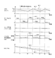
- FIG. 2 is a time chart for explaining an overview of the inertial traveling control in the first embodiment.
- the horizontal axis represents time
- the vertical axis represents vehicle speed SPD, output of the motor generator, required power from the user, charge / discharge power of the power storage device, and SOC of the power storage device.
- discharging electric power is represented by the positive value and charging electric power is represented by the negative value.
- the power required by the user is given as a substantially constant value.
- the output of the motor generator 130 is continuously output with a substantially constant magnitude as indicated by a broken line W13 in FIG.
- the vehicle speed SPD is maintained substantially constant as indicated by a broken line W11 in FIG.
- acceleration traveling with the driving force of motor generator 130 in a high output state and inertial traveling with the driving force of motor generator 130 in a low output state are repeated alternately.
- the inertial traveling control of the first embodiment is not applied, and the motor output PM1 is continuously output.
- the motor generator 130 is again set to the low output state (time t3 in FIG. 2), and inertial running is executed.
- motor generator 130 is switched to a high output state, and when vehicle speed SPD further increases to upper limit value UL, motor generator 130 is switched to a low output state.
- the motor output and acceleration time when the motor generator performs acceleration traveling can be arbitrarily set.
- the acceleration time may be set to a predetermined time, and the motor output may be set such that the vehicle speed SPD can be increased from the lower limit value LL to the upper limit value UL within that period.
- the motor output used for acceleration may be set to a predetermined output, and the acceleration time may be achieved. If the acceleration time is too short, a large power is required, and torque shock may occur. On the other hand, if the motor output is too small, the acceleration time, that is, the drive time of the motor generator becomes long, and it becomes difficult to perform inertial running. Therefore, the acceleration time and the motor output during acceleration are appropriately set in consideration of drivability and energy efficiency.
- the driving force changing operation as shown in FIG. 2 is executed when the power required by the user is substantially constant. That is, the driving force changing operation is not executed at the time of acceleration and deceleration when the power required by the user fluctuates.
- FIG. 3 and FIG. 4 are diagrams for explaining operations during acceleration and deceleration, respectively, when inertial traveling control is applied. 3 and 4, similarly to FIG. 2, the horizontal axis represents time, and the vertical axis represents vehicle speed SPD, output of the motor generator, required power from the user, charge / discharge power of the power storage device, and power storage. The SOC of the device is shown.
- the driving force changing operation is executed at vehicle speed V1 until time t24, similarly to time t14 in FIG. 3.
- regenerative braking may be performed by the motor generator 130 during a period when the deceleration request is received.
- motor generator 130 outputs negative motor output PM8B by regenerative power generation (one-dot chain line W34 in FIG. 4) and charges power storage device 110 with the generated power (one-dot chain line W37 in FIG. 4). .
- the SOC increases (one-dot chain line W40 in FIG. 4).
- the SOC change indicated by the broken line W39 in FIG. 4 when the inertial traveling control is not applied shows a state in which the motor generator 130 performs regenerative braking at the time of deceleration request (time t24 to t25). Therefore, the SOC increases from time t24 to t25.
- inertial running is executed without regenerative braking at the time of deceleration request (time t24 to t25)
- motor generator 130 is low during time t24 to t25. Since it is driven in the output state, the SOC of the broken line W39 in FIG. 4 slightly decreases.
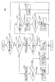
- FIG. 5 is a flowchart for illustrating an inertial traveling control process executed by ECU 300 in the first embodiment.
- Each step in the flowchart shown in FIG. 5 and FIGS. 7, 10, 12, 14, and 16 described later is realized by executing a program stored in advance in ECU 300 at a predetermined cycle.
- dedicated hardware electronic circuit
- step S 100 determines in step (hereinafter, step is abbreviated as S) 100 whether inertial running control is selected based on mode signal MOD set by the user. Determine.
- mode signal MOD is set to OFF and inertial running control is not selected (NO in S100)
- the subsequent processing is skipped, and ECU 300 returns the processing to the main routine.
- mode signal MOD is set to ON and inertial running control is selected (YES in S100)
- the process proceeds to S110, and ECU 300 next receives a request from user based on required torque TR. It is determined whether or not the required power is substantially constant.
- the process proceeds to S120, and ECU 300 selects to execute the driving force changing operation.
- the motor generator 130 is set to a low output state and inertial running is executed. .
- ECU 300 determines in S130 whether vehicle speed SPD has increased to upper limit value UL of the allowable speed range.
- the motor generator 130 is set to the low output state and the inertial running is executed. Therefore, the vehicle speed SPD is lower than the upper limit value UL and the vehicle speed SPD gradually decreases. To do.
- the driving force changing operation as described above is executed so that the vehicle speed SPD is maintained within the allowable speed range.
- the driving force changing operation in which the inertial traveling and the acceleration traveling are repeated can be executed in a state where the required power from the user is almost constant. Efficiency can be improved.
- Patent Document 4 For a vehicle that travels with the driving force of an engine, for example, as disclosed in Japanese Patent Application Laid-Open No. 2007-187090 (Patent Document 4), a technology for traveling while repeatedly driving and stopping the engine during traveling is known.
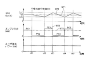
- FIG. 6 is a time chart for explaining an overview of inertial running control in the second embodiment using the engine as a drive source.
- the horizontal axis represents time
- the vertical axis represents vehicle speed SPD, engine output, and user required power.
- the engine output is continuously output at a substantially constant magnitude as indicated by a broken line W73 in FIG.
- the vehicle speed SPD is maintained substantially constant as indicated by a broken line W71 in FIG.
- FIG. 7 is a flowchart for illustrating an inertial traveling control process executed by the ECU in the second embodiment.
- steps S140, S142, S144, S146, and S148 in the flowchart of FIG. 5 of the first embodiment are replaced with S140 #, S142 #, S144 #, S146 #, and S148 #, respectively.
- the processing of each replaced step is different only in that the driving force is output from the engine instead of the motor generator, and the other processing contents are the same as those in FIG. Therefore, although detailed description of the processing contents will not be repeated, generally, when inertial running control is selected and the user request power is constant, the engine is in a high output state when the vehicle speed decreases to the lower limit value. When the vehicle speed increases to the upper limit value, the engine is switched to a low output state.
- Embodiment 3 describes a case where inertial traveling control is applied to a vehicle that travels using driving forces from a plurality of driving sources.
- FIG. 8 is an overall block diagram of vehicle 100A according to the third embodiment.
- the vehicle 100A is a hybrid vehicle that uses a rotating electrical machine and an engine that is an internal combustion engine as drive sources.
- the PCU 120 in FIG. 1 is replaced with a PCU 120A, and motor generators 130A and 130B and an engine 160 are provided as drive sources in place of the motor generator 130.
- motor generators 130A and 130B and an engine 160 are provided as drive sources in place of the motor generator 130.
- FIG. 8 the description of the same elements as those in FIG. 1 will not be repeated.
- PCU 120A includes a converter 121, inverters 122A and 122B, capacitors C1 and C2, and voltage sensors 180 and 185.
- Inverters 122A and 122B are connected in parallel to converter 121 via power lines PL2 and NL1.
- Inverter 122A is controlled by control signal PWI1 from ECU 300, converts DC power from converter 121 to AC power, and drives motor generator 130A (hereinafter also referred to as “MG1”). Inverter 122 ⁇ / b> A converts AC power generated by motor generator 130 ⁇ / b> A into DC power, and charges power storage device 110 via converter 121.
- Inverter 122B is controlled by control signal PWI2 from ECU 300, converts DC power from converter 121 to AC power, and drives motor generator 130B (hereinafter also referred to as “MG2”). Inverter 122 ⁇ / b> B converts AC power generated by motor generator 130 ⁇ / b> B into DC power, and charges power storage device 110 via converter 121.
- Each output shaft of motor generators 130A and 130B is coupled to a power transmission gear 140A configured to include a power split mechanism such as a planetary gear. Then, the driving force from motor generators 130 ⁇ / b> A and 130 ⁇ / b> B is transmitted to driving wheel 150.
- a power transmission gear 140A configured to include a power split mechanism such as a planetary gear.
- motor generators 130A and 130B are also coupled to engine 160 through power transmission gear 140A.
- Engine 160 is controlled by control signal DRV from ECU 300.
- the driving force generated from engine 160 is transmitted to driving wheel 150 and motor generator 130A via power transmission gear 140A.
- ECU 300 cooperatively controls the driving forces generated by motor generators 130A and 130B and engine 160 to cause the vehicle to travel.
- motor generator 130A is used as a starter motor when starting engine 160, and exclusively used as a generator that generates power by being driven by engine 160.
- Motor generator 130 ⁇ / b> B is exclusively used as an electric motor for driving drive wheels 150 using electric power from power storage device 110.
- FIG. 8 shows an example of a configuration in which two motor generators and one engine are provided.
- the number of motor generators is not limited to this. For example, even if there is one motor generator, Good. Or the case where more than two motor generators are provided may be sufficient.
- FIG. 9 A first example of inertial traveling control in the third embodiment will be described with reference to FIGS. 9 and 10.
- the horizontal axis indicates time
- the vertical axis indicates the vehicle speed SPD, the output of the motor generator, the required power from the user, the charge of the power storage device.
- the discharge power and the SOC of the power storage device are shown.
- the driving power of motor generator 130B (MG2) is output at a low output, as in the description in the first embodiment.
- the driving force changing operation is repeated in which the inertial traveling in the state and the acceleration traveling in which the driving force of MG2 is set to the high output state are repeated.
- engine 160 is cranked and started by motor generator 130A (MG1) prior to acceleration traveling by MG2 (FIG. 9 at time t34).
- the MG2 is switched to the low output state and the engine 160 is stopped, and the inertial running is executed again.
- the driving force (output) generated by MG2 is set smaller than when engine 160 is not driven (PM5C ⁇ PM3C, PM7C). This is because when the engine 160 is driven at an excessively low load, the efficiency of the engine 160 itself may be deteriorated. That is, the engine 160 can be driven at a more efficient operating point by causing the engine 160 to output a certain amount of driving force. Along with this, the driving force generated in MG2 is reduced to reduce the power consumption in MG2, thereby improving the power consumption.
- the driving force generated by MG2 may be set to zero when the power storage device 110 using MG1 can be charged while performing acceleration traveling only by the driving force from engine 160.
- charging of the power storage device 110 by driving the engine 160 is completed in one acceleration travel.
- a plurality of continuous acceleration travels are performed.
- the engine 160 may be driven during this period.
- FIG. 10 is a flowchart for illustrating an inertial traveling control process executed by ECU 300 in the first example of the third embodiment.
- steps S140, S142, S144, S146, and S148 of FIG. 5 described in the first embodiment are replaced with S140A, S142A, S144A, S146A, and S148A, respectively, and steps S150 and S160 are added. It has become.
- steps S150 and S160 are added. It has become.
- FIG. 10 the description of the same steps as those in FIG. 5 will not be repeated.
- steps S150 and S160 added in FIG. 10 are processes used when charging power storage device 110 with the generated power of MG1.
- S140A, S142A, S144A, S146A, and S148A in FIG. 10 are related to engine 160 in addition to motor generator 130B (MG2) in S140, S142, S144, S146, and S148 in FIG. The driving conditions are added.
- motor generator 130B MG2
- ECU 300 reduces vehicle speed SPD to lower limit value LL (YES in S135).
- MG2 is switched to the high output state and the acceleration running is executed (S142A).
- ECU 300 switches MG2 to a low output state and executes inertial running (S140A).
- ECU 300 determines in S150 whether or not the SOC falls below a predetermined threshold value and power storage device 110 needs to be charged to recover the SOC. .
- ECU 300 when the user requested power fluctuates (NO in S110) and the driving force change operation is interrupted (S125), ECU 300 is accelerating (YES in S127), MG2 or MG2 and the engine Accelerate using 160 together (S146A). If the vehicle is decelerating (NO in S127), ECU 300 stops engine 160 and switches MG2 to the low output state to decelerate (S148A). In the case of deceleration, the MG2 regeneration operation may be executed to decelerate.
- a hybrid vehicle including an engine and a motor generator
- the vehicle generator travels by executing a driving force changing operation for the motor generator. It is possible to improve the energy efficiency of the hour. Further, when the SOC decreases, it is possible to recover the SOC by driving the engine during acceleration driving of the driving force changing operation and generating power using the motor generator while continuing the driving force changing operation. It becomes.
- engine 160 is driven by interval operation during acceleration traveling during inertial traveling control even in a case other than the state where power storage device 110 needs to be charged. The case will be described.
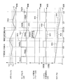
- FIG. 11 is a time chart for explaining a second example of the inertial traveling control in the third embodiment.
- the drive pattern of the engine 160 is different from that in FIG. 9 in the first example, and in addition to the period for recovering the SOC during acceleration travel (time t46 to t47 in FIG. 11), The engine 160 is also driven in a period in which another acceleration traveling is executed (time t43 to t44, t49 to t50 in FIG. 11).
- vehicle 100 travels using the driving force generated by both MG 2 and engine 160.
- the engine 160 is cranked by the MG1 immediately before the acceleration travel is executed (time t42, t45, t48 in FIG. 11).
- the ratio of the driving force distributed to MG2 and engine 160 when executing the acceleration travel is appropriately determined in consideration of the efficiency of MG2 and engine 160. Therefore, depending on the efficiency of MG2 and engine 160, the driving force distributed to MG2 may be greater than the driving force distributed to engine 160, and vice versa.
- FIG. 12 is a flowchart for explaining an inertial traveling control process executed by the ECU 300 in the example of FIG.
- steps S142A and S160 in the flowchart of FIG. 10 for the first example are replaced with S142B and S160B, respectively.
- FIG. 12 the description of the same steps as those in FIG. 10 will not be repeated.
- ECU 300 causes vehicle speed SPD to decrease to lower limit value LL. (YES in S135), MG2 is switched to the high output state, and engine 160 is driven to execute acceleration travel (S142B).
- ECU 300 stops engine 160 and switches MG2 to a low output state to execute inertial running (S140A).
- a driving force changing operation is performed for the motor generator.
- the engine it is possible to improve the energy efficiency during traveling of the vehicle while ensuring the required driving force by performing inertial traveling such as performing interval operation.
- the SOC decreases, it is possible to recover the SOC by increasing the driving force in the interval operation of the engine and performing power generation using the motor generator.
- the drive timing and the stop timing of the motor generator and the engine are described as being substantially the same for ease of explanation.
- the drive / stop timings of the motor generator and the engine do not need to be exactly the same. That is, these timings can be set as appropriate in consideration of responsiveness of driving force in the motor generator and the engine.
- the drive / stop timing of the motor generator with relatively high responsiveness may be used as a reference, and the drive / stop timing of the engine may be delayed or advanced accordingly.
- the engine is started every time when the driving force of the engine is required.
- the engine is started and stopped repeatedly, a loss may occur in the starting operation.
- it since it takes time to operate the engine independently, it may be difficult to generate a driving force with good response.
- the driving force changing operation is performed while the engine is kept in the driving state.
- the motor generator the case of performing inertial running by performing interval operation will be described.
- FIG. 13 is a time chart for explaining a first example of the inertial traveling control in the fourth embodiment.
- motor generator 130 ⁇ / b> B accelerates by the traveling pattern in which inertial traveling is stopped by stopping the generation of driving force and the driving force. Interval operation is performed to switch the running pattern.
- engine 160 is cranked by motor generator 130A (MG1) and starts.
- MG1 motor generator 130A
- P1E low output state
- the driving force of engine 160 is set to a high output state during the subsequent acceleration traveling period, and MG1 is driven to charge power storage device 110 (FIG. 13 at time t75 to t76).
- the engine driving force is switched to a low output state.
- the driving force generated by MG2 in the acceleration traveling period in which engine 160 is switched to the high output state is the driving force in the acceleration traveling period in which engine 160 is in the low output state. It is set lower than that.
- the output from the engine 160 may be transmitted to the drive wheels 150 or may be made non-transmitted by an engagement device (not shown) such as a clutch.
- FIG. 14 is a flowchart for explaining an inertial traveling control process executed by the ECU 300 in the example of FIG.
- FIG. 14 the description of the same steps as those in FIG. 10 will not be repeated.
- ECU 300 stops MG2 and executes inertial running. Then, ECU 300 determines in S121 whether engine 160 is already in operation.
- ECU 300 starts engine 160 in S122. At this time, after completion of the self-sustained operation, the engine 160 is first operated in a low output state where the driving force is low. Then, the process proceeds to S130.
- ECU 300 skips S122 and advances the process to S130.
- ECU 300 maintains the operating state of MG2 and engine 160 in S144C. That is, ECU 300 keeps MG2 in a stopped state and keeps engine 160 in a low output state.
- ECU 300 drives MG2 and executes accelerated traveling in S142C. At this time, ECU 300 maintains the low output state of engine 160.
- ECU 300 determines in S150 that the SOC falls below a predetermined threshold value and the SOC needs to be recovered (YES in S150)
- ECU 300 proceeds to S160C to increase the driving force of engine 160.
- the MG1 is driven in a high output state, and the power storage device 110 is charged with the power generated by the MG1.
- SOC recovery is not required (NO in S150)
- ECU 300 continues the operation state of S142C.
- ECU 300 when the user requested power fluctuates (NO in S110) and the driving force change operation is interrupted (S125), ECU 300 is accelerating (YES in S127), MG2, engine 160, or The MG2 and the engine 160 are used in combination to accelerate (S146C). If the vehicle is decelerating (NO in S127), ECU 300 reduces the driving force of engine 160 and decelerates by stopping MG2 or executing the regeneration operation of MG2 (S148C).
- the motor generator By performing control according to the above-described process, in a hybrid vehicle including an engine and a motor generator, when the power required by the user is substantially constant, the motor generator performs an interval operation while the engine requires a driving force. By executing the change operation, it is possible to reduce the loss at the time of starting the engine and improve the energy efficiency at the time of traveling the vehicle. Further, when the SOC decreases, it is possible to recover the SOC by increasing the driving force of the engine during acceleration traveling and performing power generation using the motor generator.
- the second example in the fourth embodiment is a case where engine 160 is driven in a high output state during acceleration traveling during execution of inertial traveling control, even in a case other than the state where power storage device 110 needs to be charged. .
- this is in addition to the driving force generated by the motor generator in order to realize the user required power, for example, when traveling on a highway. This is applied when the driving force generated by the engine is also required.
- FIG. 15 is a time chart for explaining a second example of the inertial traveling control in the fourth embodiment.
- the driving pattern of the engine 160 is different from that in FIG. 13 in the first example, and in addition to the period for recovering the SOC during acceleration travel (time t85 to t86 in FIG. 15), The engine 160 is also driven during a period in which another acceleration traveling is executed (time t83 to t84, t87 to t88 in FIG. 15).
- vehicle 100 travels using the driving force generated by both MG 2 and engine 160.
- the ratio of the driving force distributed to MG2 and engine 160 when executing the acceleration travel is appropriately determined in consideration of the efficiency of MG2 and engine 160.
- FIG. 16 is a flowchart for illustrating an inertial traveling control process executed by ECU 300 in the example of FIG.
- steps S142C and S160C in the flowchart of FIG. 14 for the first example are replaced with S142D and S160D, respectively.
- the description of the same steps as those in FIG. 14 will not be repeated.
- ECU 300 stops MG2 and executes inertial running. At the same time, the engine 160 is started (S122).
- ECU 300 maintains the operating state of MG2 and engine 160 in S144C. That is, ECU 300 keeps MG2 in a stopped state and keeps engine 160 in a low output state.
- ECU 300 drives MG2 and shifts engine 160 to a high output state in S142D, and driving force from MG2 and engine 160 Accelerate running using
- ECU 300 determines in S150 that the SOC is below a predetermined threshold value and the SOC needs to be recovered (YES in S150)
- ECU 300 proceeds to S160D, and ECU 300 causes engine 160 to In order to drive using MG2 and the driving force from engine 160 while driving MG1, the ratio of the driving force generated by engine 160 to the total driving force required is increased.
- SOC recovery is not required (NO in S150)
- ECU 300 continues the operation state of S142D.
- the hybrid vehicle provided with an engine and a motor generator as a plurality of drive sources has been described as an example.
- the present invention is illustrated as a plurality of drive sources, for example, in FIG.
- the present invention can also be applied to a vehicle having another configuration such as an electric vehicle having a twin motor configuration capable of traveling using driving power from two motor generators.
- a vehicle 100B in FIG. 17 has a configuration in which the engine 160 is not provided in the vehicle 100A in FIG. 8, and the vehicle 100B travels using the driving power of both the motor generator 130A (MG1) and the motor generator 130B (MG2). To do.
- MG1 motor generator 130A
- MG2 motor generator 130B
- the power storage device 110 cannot be charged as in the third and fourth embodiments, but in FIG. 9 and the like in the third embodiment, the driving force of the engine 160 is replaced with the output of MG1. It is possible to perform driving force change operation.
- the present invention can be applied even when MG1 is also used as an electric motor instead of a generator and travels using driving forces generated by three driving sources MG1, MG2 and engine 160. Is possible.
Abstract
Description
好ましくは、駆動源は、回転電機を含む。制御装置は、回転電機を用いて駆動力変更運転を実行する。
図1は、本発明の実施の形態1に従う車両100の全体ブロック図である。以下で詳細に説明されるように、車両100は、駆動源として回転電機を用いる電気自動車である。
実施の形態1は、モータジェネレータを駆動源とする電気自動車を例として説明したが、上述の駆動力変更制御は、駆動源としてエンジンを有する車両においても適用可能である。
実施の形態1および2では、駆動源として1台のモータジェネレータ、あるいはエンジンが単独で設けられる場合における慣性走行制御について説明した。
図9および図10を用いて、実施の形態3における慣性走行制御の第1の例を説明する。図9においては、実施の形態1における図2~図4と同様に、横軸には時間が示され、縦軸には車速SPD、モータジェネレータの出力、ユーザからの要求パワー、蓄電装置の充放電電力、および蓄電装置のSOCが示される。
図9および図10で説明した第1の例では、蓄電装置110の充電が必要である状態においてのみ、エンジン160がMG2とともに駆動される場合について説明した。すなわち、蓄電装置110の充電を行なうとき以外は、MG2によって発生される駆動力のみで走行する、いわゆるEV(Electric Vehicle)走行が実行される場合である。
実施の形態3においては、モータジェネレータとエンジンとを備えるハイブリッド車両において、モータジェネレータについて駆動力変更制御を実行し、エンジンについてインターバル運転を実行する慣性走行制御について説明した。
図13および図14を用いて、実施の形態4における慣性走行制御の第1の例を説明する。図13は実施の形態4における慣性走行制御の第1の例を説明するためのタイムチャートである。
実施の形態4における第2の例は、蓄電装置110の充電が必要である状態以外の場合においても、慣性走行制御を実行中の加速走行時に、エンジン160を高出力状態で駆動する場合である。これは、実施の形態3における第2の例で説明したように、たとえば、高速道路を走行するような場合に、ユーザ要求パワーを実現するために、モータジェネレータで発生される駆動力に加えてエンジンで発生される駆動力も必要となるような場合に適用される。
上記の実施の形態3および4においては、複数の駆動源としてエンジンとモータジェネレータとが備えられるハイブリッド車両を例として説明したが、本発明は、複数の駆動源として、たとえば、図17に示されるような、2つのモータジェネレータからの駆動力を用いて走行することが可能なツインモータ構成の電気自動車などの、他の構成を有する車両にも適用可能である。
Claims (20)
- 車両であって、
前記車両(100)の走行駆動力を発生する駆動源(130,130B,160)と、
前記駆動源(130,130B,160)を制御するための制御装置(300)とを備え、
前記制御装置(300)は、前記駆動源(130,130B,160)について、所定のレベルの駆動力を発生させる第1の状態と、前記第1の状態よりも大きい駆動力を発生させる第2の状態とを切換えながら前記車両(100)を走行させる駆動力変更運転を実行する、車両。 - 前記制御装置(300)は、ユーザからの要求駆動力の変化が所定範囲内の場合に、前記駆動力変更運転を実行する、請求項1に記載の車両。
- 前記制御装置(300)は、前記駆動力変更運転の実行中は、前記車両(100)の速度が許容範囲内に維持されるように、前記第1および第2の状態を切換える、請求項2に記載の車両。
- 前記制御装置(300)は、前記車両(100)の速度が前記許容範囲の上限まで上昇したことに応答して前記第1の状態に切換え、前記車両(100)の速度が前記許容範囲の下限まで低下したことに応答して前記第2の状態に切換える、請求項3に記載の車両。
- 前記第1の状態における駆動力は、前記車両(100)の速度を維持することが可能な一定出力の基準駆動力よりも小さく設定され、
前記第2の状態における駆動力は、前記基準駆動力よりも大きく設定される、請求項1に記載の車両。 - 前記車両(100)は、前記第1の状態においては、主に前記車両(100)の慣性力によって走行する、請求項5に記載の車両。
- 前記駆動源は、回転電機(130,130B)を含み、
前記制御装置(300)は、前記回転電機(130,130B)を用いて前記駆動力変更運転を実行する、請求項1に記載の車両。 - 前記車両(100)の駆動力を発生することが可能であり、前記駆動源(130B)とは異なる他の駆動源としてエンジン(160)をさらに備え、
前記制御装置(300)は、前記回転電機(130B)により前記駆動力変更運転を実行している期間に、前記エンジン(160)について、前記エンジン(160)からの駆動力の発生を停止する第1の走行パターンと、前記エンジン(160)が発生する駆動力を走行に用いる第2の走行パターンとを切換えるインターバル運転を実行する、請求項7に記載の車両。 - 前記制御装置(300)は、前記エンジン(160)が前記第2の走行パターンの場合に前記回転電機(130B)が前記第2の状態となるときは、前記エンジン(160)が前記第1の走行パターンの場合に前記回転電機(130B)が前記第2の状態となるときよりも、前記回転電機(130B)により発生される駆動力を低下する、請求項8に記載の車両。
- 前記制御装置(300)は、前記回転電機(130B)が前記第2の状態である期間に、前記エンジン(160)を前記第2の走行パターンに切換える、請求項8に記載の車両。
- 前記回転電機(130B)に電力を供給する蓄電装置(110)と、
前記エンジン(160)により駆動されて、前記蓄電装置(110)を充電するための電力を発電するように構成された発電機(130A)をさらに備え、
前記制御装置(300)は、前記発電機(130A)を駆動して前記蓄電装置(110)を充電する場合に、前記エンジン(160)を前記第2の走行パターンに切換える、請求項8に記載の車両。 - 前記回転電機に電力を供給する蓄電装置(110)と、
前記エンジン(160)により駆動されて、前記蓄電装置(110)を充電するための電力を発電するように構成された発電機(130A)をさらに備え、
前記制御装置(300)は、前記エンジン(160)が前記第2の走行パターンである場合に前記発電機(130A)を駆動して前記蓄電装置(110)を充電し、
前記制御装置(300)は、前記エンジン(160)が前記第2の走行パターンである場合に、前記発電機(130A)による発電を行なうときの前記エンジン(160)の駆動力が、前記発電機(130A)による発電を行なわないときの前記エンジン(160)の駆動力よりも大きくなるようにする、請求項8に記載の車両。 - 前記駆動源は、エンジン(160)を含み、
前記制御装置(300)は、前記エンジン(160)を用いて前記駆動力変更運転を実行する、請求項1に記載の車両。 - 前記車両(100)の駆動力を発生することが可能であり、前記駆動源(160)とは異なる他の駆動源として回転電機(130B)をさらに備え、
前記制御装置(300)は、前記エンジン(160)により前記駆動力変更運転を実行している期間に、前記回転電機(130B)について、前記回転電機(130B)からの駆動力の発生を停止する第1の走行パターンと、前記回転電機(130B)が発生する駆動力を走行に用いる第2の走行パターンとを切換えるインターバル運転を実行する、請求項13に記載の車両。 - 前記制御装置(300)は、前記エンジン(160)が前記第2の状態の場合に前記回転電機(130B)が前記第2の走行パターンとなるときは、前記エンジン(160)が前記第1の状態の場合に前記回転電機(130B)が前記第2の状態となるときよりも、前記回転電機(130B)により発生される駆動力を低下する、請求項14に記載の車両。
- 前記制御装置(300)は、前記エンジン(160)が前記第2の状態である期間に、前記回転電機(130B)を前記第2の走行パターンに切換える、請求項14に記載の車両。
- 前記回転電機(130B)に電力を供給する蓄電装置(110)と、
前記エンジン(160)により駆動されて、前記蓄電装置(110)を充電するための電力を発電するように構成された発電機(130A)をさらに備え、
前記制御装置(300)は、前記発電機(130A)を駆動して前記蓄電装置(110)を充電する場合に、前記エンジン(160)を前記第2の状態に切換える、請求項14に記載の車両。 - 前記回転電機に電力を供給する蓄電装置(110)と、
前記エンジン(160)により駆動されて、前記蓄電装置(110)を充電するための電力を発電するように構成された発電機(130A)をさらに備え、
前記制御装置(300)は、前記エンジン(160)が前記第2の状態である場合に前記発電機(130A)を駆動して前記蓄電装置(110)を充電し、
前記制御装置(300)は、前記エンジン(160)が前記第2の状態である場合に、前記発電機(130A)による発電を行なうときの前記エンジン(160)の駆動力が、前記発電機(130A)による発電を行なわないときの前記エンジン(160)の駆動力よりも大きくなるようにする、請求項14に記載の車両。 - 前記車両(100)の駆動力を発生することが可能であり、前記駆動源とは異なる他の駆動源をさらに備え、
前記駆動源および前記他の駆動源は、それぞれ第1の回転電機(130A)および第2の回転電機(130B)であり、
前記制御装置(300)は、前記第1の回転電機(130A)を用いて前記駆動力変更運転を実行し、
前記制御装置(300)は、前記第1の回転電機(130A)により前記駆動力変更運転を実行している期間に、前記第2の回転電機(130B)について、前記第2の回転電機(130B)からの駆動力の発生を停止する第1の走行パターンと、前記第2の回転電機(130B)が発生する駆動力を走行に用いる第2の走行パターンとを切換えるインターバル運転を実行する、請求項1に記載の車両。 - 走行駆動力を発生する駆動源(130,130B,160)を有する車両の制御方法であって、
前記駆動源(130,130B,160)を、所定のレベルの駆動力を発生させる第1の状態にするステップと、
前記駆動源(130,130B,160)を、前記第1の状態よりも大きい駆動力を発生させる第2の状態にするステップと、
前記第1および第2の状態を切換えながら前記車両(100)を走行させる駆動力変更運転を実行するステップとを備える、車両の制御方法。
Priority Applications (5)
| Application Number | Priority Date | Filing Date | Title |
|---|---|---|---|
| CN201180073687.6A CN103826901B (zh) | 2011-09-27 | 2011-09-27 | 车辆和车辆的控制方法 |
| PCT/JP2011/071976 WO2013046311A1 (ja) | 2011-09-27 | 2011-09-27 | 車両および車両の制御方法 |
| US14/347,036 US9199542B2 (en) | 2011-09-27 | 2011-09-27 | Vehicle and method of controlling vehicle |
| EP11873041.5A EP2762349B1 (en) | 2011-09-27 | 2011-09-27 | Vehicle and control method for vehicle |
| JP2013535670A JP6100690B2 (ja) | 2011-09-27 | 2011-09-27 | 車両 |
Applications Claiming Priority (1)
| Application Number | Priority Date | Filing Date | Title |
|---|---|---|---|
| PCT/JP2011/071976 WO2013046311A1 (ja) | 2011-09-27 | 2011-09-27 | 車両および車両の制御方法 |
Publications (1)
| Publication Number | Publication Date |
|---|---|
| WO2013046311A1 true WO2013046311A1 (ja) | 2013-04-04 |
Family
ID=47994428
Family Applications (1)
| Application Number | Title | Priority Date | Filing Date |
|---|---|---|---|
| PCT/JP2011/071976 WO2013046311A1 (ja) | 2011-09-27 | 2011-09-27 | 車両および車両の制御方法 |
Country Status (5)
| Country | Link |
|---|---|
| US (1) | US9199542B2 (ja) |
| EP (1) | EP2762349B1 (ja) |
| JP (1) | JP6100690B2 (ja) |
| CN (1) | CN103826901B (ja) |
| WO (1) | WO2013046311A1 (ja) |
Cited By (2)
| Publication number | Priority date | Publication date | Assignee | Title |
|---|---|---|---|---|
| JP2013169942A (ja) * | 2012-02-22 | 2013-09-02 | Toyota Motor Corp | ハイブリッド自動車 |
| JP2014213634A (ja) * | 2013-04-23 | 2014-11-17 | トヨタ自動車株式会社 | ハイブリッド車両の走行制御装置 |
Families Citing this family (5)
| Publication number | Priority date | Publication date | Assignee | Title |
|---|---|---|---|---|
| CN103889771B (zh) * | 2011-10-26 | 2016-03-02 | 丰田自动车株式会社 | 车辆和车辆的控制方法 |
| EP2777981B1 (en) * | 2011-11-07 | 2016-12-21 | Toyota Jidosha Kabushiki Kaisha | Vehicle and vehicle control method |
| JP5766358B2 (ja) * | 2012-08-13 | 2015-08-19 | 三菱電機株式会社 | エンジンハイブリッド鉄道車両の推進制御装置 |
| US10293808B2 (en) * | 2017-03-03 | 2019-05-21 | Toyota Motor Engineering & Manufacturing North America, Inc. | Constant power control |
| JP7068893B2 (ja) * | 2018-03-30 | 2022-05-17 | 本田技研工業株式会社 | 車両電源システム |
Citations (7)
| Publication number | Priority date | Publication date | Assignee | Title |
|---|---|---|---|---|
| JP2005124287A (ja) * | 2003-10-15 | 2005-05-12 | Toyota Motor Corp | 車両用駆動制御装置 |
| JP2005160252A (ja) * | 2003-11-27 | 2005-06-16 | Toyota Motor Corp | 車両用走行制御装置 |
| JP2007187090A (ja) | 2006-01-13 | 2007-07-26 | Toyota Motor Corp | 速度維持制御装置 |
| JP2008520485A (ja) | 2004-11-16 | 2008-06-19 | フォルクスワーゲン・アクチェンゲゼルシャフト | ハイブリッド自動車及びハイブリッド自動車の動作制御法 |
| JP2009298232A (ja) | 2008-06-11 | 2009-12-24 | Toyota Motor Corp | ハイブリッド車およびその制御方法 |
| JP2010006309A (ja) | 2008-06-30 | 2010-01-14 | Toyota Motor Corp | 車両用制御装置 |
| JP2010093947A (ja) * | 2008-10-08 | 2010-04-22 | Masahiro Watanabe | 車両走行制御方法 |
Family Cites Families (17)
| Publication number | Priority date | Publication date | Assignee | Title |
|---|---|---|---|---|
| JPS6261832A (ja) * | 1985-09-13 | 1987-03-18 | Mazda Motor Corp | 車両の走行制御装置 |
| JPH05115108A (ja) * | 1991-10-21 | 1993-05-07 | Nissan Motor Co Ltd | 電気自動車 |
| JP3846118B2 (ja) | 1999-08-18 | 2006-11-15 | トヨタ自動車株式会社 | 駆動装置 |
| JP3832237B2 (ja) * | 2000-09-22 | 2006-10-11 | 日産自動車株式会社 | ハイブリッド車の制御装置 |
| US7360615B2 (en) * | 2004-06-09 | 2008-04-22 | General Motors Corporation | Predictive energy management system for hybrid electric vehicles |
| JP4005069B2 (ja) * | 2004-09-03 | 2007-11-07 | 本田技研工業株式会社 | ハイブリッド車両の制御装置 |
| JP2009126450A (ja) * | 2007-11-27 | 2009-06-11 | Toyota Motor Corp | ハイブリッド車及びハイブリッド車の制御方法 |
| JP4566233B2 (ja) * | 2007-12-25 | 2010-10-20 | トヨタ自動車株式会社 | ハイブリッド駆動装置の制御装置 |
| JP4596016B2 (ja) * | 2008-02-12 | 2010-12-08 | トヨタ自動車株式会社 | 車輌走行制御装置 |
| JP4743218B2 (ja) * | 2008-03-03 | 2011-08-10 | 日産自動車株式会社 | ハイブリッド車両のクラッチ制御装置 |
| JP5304350B2 (ja) * | 2009-03-12 | 2013-10-02 | トヨタ自動車株式会社 | 車両用制御装置 |
| JP2011011648A (ja) * | 2009-07-02 | 2011-01-20 | Honda Motor Co Ltd | ハイブリッド車両の制御装置 |
| JP5183594B2 (ja) * | 2009-07-31 | 2013-04-17 | 日立オートモティブシステムズ株式会社 | モータの制御装置及びそれを備えたモータシステム |
| US8626424B2 (en) * | 2009-08-05 | 2014-01-07 | GM Global Technology Operations LLC | Active coast and cruise control system and methods |
| DE102010011164B4 (de) * | 2010-03-12 | 2019-05-16 | Bayerische Motoren Werke Aktiengesellschaft | Verfahren zur Motorsteuerung in einem Hybridfahrzeug, Motorsteuerungsgerät und Hybridfahrzeug mit einem über Schubabschaltung abschaltbaren Verbrennungsmotor |
| WO2012029178A1 (ja) * | 2010-09-03 | 2012-03-08 | トヨタ自動車株式会社 | 車両の駆動制御装置 |
| JP5492745B2 (ja) * | 2010-11-16 | 2014-05-14 | 株式会社日立製作所 | 電動車両の走行制御装置 |
-
2011
- 2011-09-27 EP EP11873041.5A patent/EP2762349B1/en not_active Not-in-force
- 2011-09-27 CN CN201180073687.6A patent/CN103826901B/zh not_active Expired - Fee Related
- 2011-09-27 WO PCT/JP2011/071976 patent/WO2013046311A1/ja active Application Filing
- 2011-09-27 JP JP2013535670A patent/JP6100690B2/ja active Active
- 2011-09-27 US US14/347,036 patent/US9199542B2/en active Active
Patent Citations (7)
| Publication number | Priority date | Publication date | Assignee | Title |
|---|---|---|---|---|
| JP2005124287A (ja) * | 2003-10-15 | 2005-05-12 | Toyota Motor Corp | 車両用駆動制御装置 |
| JP2005160252A (ja) * | 2003-11-27 | 2005-06-16 | Toyota Motor Corp | 車両用走行制御装置 |
| JP2008520485A (ja) | 2004-11-16 | 2008-06-19 | フォルクスワーゲン・アクチェンゲゼルシャフト | ハイブリッド自動車及びハイブリッド自動車の動作制御法 |
| JP2007187090A (ja) | 2006-01-13 | 2007-07-26 | Toyota Motor Corp | 速度維持制御装置 |
| JP2009298232A (ja) | 2008-06-11 | 2009-12-24 | Toyota Motor Corp | ハイブリッド車およびその制御方法 |
| JP2010006309A (ja) | 2008-06-30 | 2010-01-14 | Toyota Motor Corp | 車両用制御装置 |
| JP2010093947A (ja) * | 2008-10-08 | 2010-04-22 | Masahiro Watanabe | 車両走行制御方法 |
Non-Patent Citations (1)
| Title |
|---|
| See also references of EP2762349A4 |
Cited By (2)
| Publication number | Priority date | Publication date | Assignee | Title |
|---|---|---|---|---|
| JP2013169942A (ja) * | 2012-02-22 | 2013-09-02 | Toyota Motor Corp | ハイブリッド自動車 |
| JP2014213634A (ja) * | 2013-04-23 | 2014-11-17 | トヨタ自動車株式会社 | ハイブリッド車両の走行制御装置 |
Also Published As
| Publication number | Publication date |
|---|---|
| US20150021916A1 (en) | 2015-01-22 |
| JPWO2013046311A1 (ja) | 2015-03-26 |
| JP6100690B2 (ja) | 2017-03-22 |
| EP2762349A1 (en) | 2014-08-06 |
| US9199542B2 (en) | 2015-12-01 |
| CN103826901A (zh) | 2014-05-28 |
| EP2762349B1 (en) | 2017-10-25 |
| CN103826901B (zh) | 2016-04-20 |
| EP2762349A4 (en) | 2016-03-09 |
Similar Documents
| Publication | Publication Date | Title |
|---|---|---|
| JP5692405B2 (ja) | 車両および車両の制御方法 | |
| JP5804074B2 (ja) | 車両および車両の制御方法 | |
| JP6100690B2 (ja) | 車両 | |
| JP5696791B2 (ja) | 車両および車両の制御方法 | |
| JP5675441B2 (ja) | 車両の制御装置 | |
| JP5696790B2 (ja) | 車両および車両の制御方法 | |
| JP5811181B2 (ja) | 車両および車両の制御方法 | |
| JPWO2012101796A1 (ja) | 車両および車両用制御方法 | |
| WO2013046310A1 (ja) | 車両および車両の制御方法 | |
| WO2013046312A1 (ja) | 車両および車両の制御方法 | |
| CN103889771B (zh) | 车辆和车辆的控制方法 | |
| JP6149814B2 (ja) | ハイブリッド車両 | |
| WO2013061414A1 (ja) | 車両および車両の制御方法 | |
| JP5772519B2 (ja) | 車両および車両の制御方法 | |
| JPWO2013046310A1 (ja) | 車両および車両の制御方法 | |
| JPWO2013061414A1 (ja) | 車両および車両の制御方法 | |
| JP5765192B2 (ja) | 車両および車両の制御方法 | |
| JPWO2013046312A1 (ja) | 車両および車両の制御方法 | |
| JP2013086725A (ja) | 車両および車両の制御方法 |
Legal Events
| Date | Code | Title | Description |
|---|---|---|---|
| WWE | Wipo information: entry into national phase |
Ref document number: 201180073687.6 Country of ref document: CN |
|
| 121 | Ep: the epo has been informed by wipo that ep was designated in this application |
Ref document number: 11873041 Country of ref document: EP Kind code of ref document: A1 |
|
| ENP | Entry into the national phase |
Ref document number: 2013535670 Country of ref document: JP Kind code of ref document: A |
|
| WWE | Wipo information: entry into national phase |
Ref document number: 14347036 Country of ref document: US |
|
| NENP | Non-entry into the national phase |
Ref country code: DE |
|
| REEP | Request for entry into the european phase |
Ref document number: 2011873041 Country of ref document: EP |
|
| WWE | Wipo information: entry into national phase |
Ref document number: 2011873041 Country of ref document: EP |