WO2013042767A1 - Appareil de surveillance de l'environnement d'un véhicule - Google Patents
Appareil de surveillance de l'environnement d'un véhicule Download PDFInfo
- Publication number
- WO2013042767A1 WO2013042767A1 PCT/JP2012/074229 JP2012074229W WO2013042767A1 WO 2013042767 A1 WO2013042767 A1 WO 2013042767A1 JP 2012074229 W JP2012074229 W JP 2012074229W WO 2013042767 A1 WO2013042767 A1 WO 2013042767A1
- Authority
- WO
- WIPO (PCT)
- Prior art keywords
- vehicle
- monitoring device
- region
- image
- periphery monitoring
- Prior art date
Links
- 238000012544 monitoring process Methods 0.000 title claims abstract description 116
- 238000011156 evaluation Methods 0.000 claims description 68
- 238000012806 monitoring device Methods 0.000 claims description 47
- 238000003384 imaging method Methods 0.000 claims description 32
- 238000001514 detection method Methods 0.000 claims description 17
- 241001465754 Metazoa Species 0.000 description 49
- 238000000034 method Methods 0.000 description 32
- 230000006870 function Effects 0.000 description 23
- 230000008569 process Effects 0.000 description 19
- 238000010586 diagram Methods 0.000 description 16
- 238000012545 processing Methods 0.000 description 16
- 238000004364 calculation method Methods 0.000 description 12
- 238000013459 approach Methods 0.000 description 4
- 230000008859 change Effects 0.000 description 4
- 230000000694 effects Effects 0.000 description 4
- 230000004048 modification Effects 0.000 description 4
- 238000012986 modification Methods 0.000 description 4
- 230000006399 behavior Effects 0.000 description 3
- 238000010835 comparative analysis Methods 0.000 description 3
- 238000005401 electroluminescence Methods 0.000 description 3
- 230000006872 improvement Effects 0.000 description 3
- 230000011218 segmentation Effects 0.000 description 3
- 230000000007 visual effect Effects 0.000 description 3
- 125000002066 L-histidyl group Chemical group [H]N1C([H])=NC(C([H])([H])[C@](C(=O)[*])([H])N([H])[H])=C1[H] 0.000 description 2
- 238000006243 chemical reaction Methods 0.000 description 2
- 238000004040 coloring Methods 0.000 description 2
- 238000000605 extraction Methods 0.000 description 2
- 238000003825 pressing Methods 0.000 description 2
- 230000004044 response Effects 0.000 description 2
- 239000013589 supplement Substances 0.000 description 2
- 230000007704 transition Effects 0.000 description 2
- 241000271566 Aves Species 0.000 description 1
- 241000282472 Canis lupus familiaris Species 0.000 description 1
- 241000282994 Cervidae Species 0.000 description 1
- 241000283086 Equidae Species 0.000 description 1
- 241000282326 Felis catus Species 0.000 description 1
- 241000282412 Homo Species 0.000 description 1
- 241000124008 Mammalia Species 0.000 description 1
- 241001494479 Pecora Species 0.000 description 1
- 230000036626 alertness Effects 0.000 description 1
- 230000004397 blinking Effects 0.000 description 1
- 238000004891 communication Methods 0.000 description 1
- 150000001875 compounds Chemical class 0.000 description 1
- 230000003111 delayed effect Effects 0.000 description 1
- 239000000284 extract Substances 0.000 description 1
- 239000000446 fuel Substances 0.000 description 1
- 230000005484 gravity Effects 0.000 description 1
- 238000009434 installation Methods 0.000 description 1
- 239000004973 liquid crystal related substance Substances 0.000 description 1
- 230000003287 optical effect Effects 0.000 description 1
- 238000012502 risk assessment Methods 0.000 description 1
Images


Classifications
-
- G—PHYSICS
- G06—COMPUTING; CALCULATING OR COUNTING
- G06V—IMAGE OR VIDEO RECOGNITION OR UNDERSTANDING
- G06V20/00—Scenes; Scene-specific elements
- G06V20/50—Context or environment of the image
- G06V20/56—Context or environment of the image exterior to a vehicle by using sensors mounted on the vehicle
- G06V20/58—Recognition of moving objects or obstacles, e.g. vehicles or pedestrians; Recognition of traffic objects, e.g. traffic signs, traffic lights or roads
-
- B—PERFORMING OPERATIONS; TRANSPORTING
- B60—VEHICLES IN GENERAL
- B60R—VEHICLES, VEHICLE FITTINGS, OR VEHICLE PARTS, NOT OTHERWISE PROVIDED FOR
- B60R1/00—Optical viewing arrangements; Real-time viewing arrangements for drivers or passengers using optical image capturing systems, e.g. cameras or video systems specially adapted for use in or on vehicles
- B60R1/20—Real-time viewing arrangements for drivers or passengers using optical image capturing systems, e.g. cameras or video systems specially adapted for use in or on vehicles
- B60R1/22—Real-time viewing arrangements for drivers or passengers using optical image capturing systems, e.g. cameras or video systems specially adapted for use in or on vehicles for viewing an area outside the vehicle, e.g. the exterior of the vehicle
- B60R1/23—Real-time viewing arrangements for drivers or passengers using optical image capturing systems, e.g. cameras or video systems specially adapted for use in or on vehicles for viewing an area outside the vehicle, e.g. the exterior of the vehicle with a predetermined field of view
- B60R1/24—Real-time viewing arrangements for drivers or passengers using optical image capturing systems, e.g. cameras or video systems specially adapted for use in or on vehicles for viewing an area outside the vehicle, e.g. the exterior of the vehicle with a predetermined field of view in front of the vehicle
-
- B—PERFORMING OPERATIONS; TRANSPORTING
- B60—VEHICLES IN GENERAL
- B60R—VEHICLES, VEHICLE FITTINGS, OR VEHICLE PARTS, NOT OTHERWISE PROVIDED FOR
- B60R1/00—Optical viewing arrangements; Real-time viewing arrangements for drivers or passengers using optical image capturing systems, e.g. cameras or video systems specially adapted for use in or on vehicles
- B60R1/20—Real-time viewing arrangements for drivers or passengers using optical image capturing systems, e.g. cameras or video systems specially adapted for use in or on vehicles
- B60R1/30—Real-time viewing arrangements for drivers or passengers using optical image capturing systems, e.g. cameras or video systems specially adapted for use in or on vehicles providing vision in the non-visible spectrum, e.g. night or infrared vision
-
- B—PERFORMING OPERATIONS; TRANSPORTING
- B60—VEHICLES IN GENERAL
- B60R—VEHICLES, VEHICLE FITTINGS, OR VEHICLE PARTS, NOT OTHERWISE PROVIDED FOR
- B60R1/00—Optical viewing arrangements; Real-time viewing arrangements for drivers or passengers using optical image capturing systems, e.g. cameras or video systems specially adapted for use in or on vehicles
- B60R1/20—Real-time viewing arrangements for drivers or passengers using optical image capturing systems, e.g. cameras or video systems specially adapted for use in or on vehicles
- B60R1/31—Real-time viewing arrangements for drivers or passengers using optical image capturing systems, e.g. cameras or video systems specially adapted for use in or on vehicles providing stereoscopic vision
-
- G—PHYSICS
- G08—SIGNALLING
- G08G—TRAFFIC CONTROL SYSTEMS
- G08G1/00—Traffic control systems for road vehicles
- G08G1/16—Anti-collision systems
- G08G1/166—Anti-collision systems for active traffic, e.g. moving vehicles, pedestrians, bikes
-
- H—ELECTRICITY
- H04—ELECTRIC COMMUNICATION TECHNIQUE
- H04N—PICTORIAL COMMUNICATION, e.g. TELEVISION
- H04N7/00—Television systems
- H04N7/18—Closed-circuit television [CCTV] systems, i.e. systems in which the video signal is not broadcast
-
- B—PERFORMING OPERATIONS; TRANSPORTING
- B60—VEHICLES IN GENERAL
- B60R—VEHICLES, VEHICLE FITTINGS, OR VEHICLE PARTS, NOT OTHERWISE PROVIDED FOR
- B60R2300/00—Details of viewing arrangements using cameras and displays, specially adapted for use in a vehicle
- B60R2300/10—Details of viewing arrangements using cameras and displays, specially adapted for use in a vehicle characterised by the type of camera system used
- B60R2300/106—Details of viewing arrangements using cameras and displays, specially adapted for use in a vehicle characterised by the type of camera system used using night vision cameras
-
- B—PERFORMING OPERATIONS; TRANSPORTING
- B60—VEHICLES IN GENERAL
- B60R—VEHICLES, VEHICLE FITTINGS, OR VEHICLE PARTS, NOT OTHERWISE PROVIDED FOR
- B60R2300/00—Details of viewing arrangements using cameras and displays, specially adapted for use in a vehicle
- B60R2300/30—Details of viewing arrangements using cameras and displays, specially adapted for use in a vehicle characterised by the type of image processing
- B60R2300/307—Details of viewing arrangements using cameras and displays, specially adapted for use in a vehicle characterised by the type of image processing virtually distinguishing relevant parts of a scene from the background of the scene
Definitions
- the present invention relates to a vehicle periphery monitoring apparatus that detects and easily displays a monitoring object around the vehicle.
- JP-A Japanese Patent Application Laid-Open
- HUD head-up display
- pedestrian candidates can be easily selected from binarized information, and grayscale information is used to determine pedestrians, thereby achieving both processing speed and determination accuracy.
- grayscale information is used to determine pedestrians, thereby achieving both processing speed and determination accuracy.
- the present invention has been made in consideration of such a problem, and an object thereof is to provide a vehicle periphery monitoring device capable of appropriately alerting a user.
- a vehicle periphery monitoring device is a device that detects a monitoring object in the periphery of the vehicle based on an imaging signal output from an imaging device mounted on the vehicle, and is a captured image represented by the imaging signal. The sub-regions of the captured image depending on whether or not each mark associated with each of the plurality of sub-regions constituting the captured image displayed on the first display unit is displayed.
- a second display unit that visualizes presence / absence information of the monitoring object in the vehicle, and when at least one of the monitoring objects is detected from the captured image, the degree of caution of the monitoring object for the vehicle is evaluated
- An attention level evaluation unit and the second display unit displays the mark in a different display form according to the attention level evaluated by the attention level evaluation unit.
- the mark when at least one monitoring object is detected from the captured image, the mark is displayed in a different display form according to the degree of caution of the monitoring object for the vehicle. For this reason, it is possible to visually notify the user of the difference in the attention level between the monitoring objects, and appropriate attention can be given.
- the degree of caution is a possibility that a vehicle occupant may misrecognize the position of the monitoring object by visually recognizing the display of the mark, and the second display unit may be misidentified.
- a plurality of the marks may be displayed simultaneously or alternately corresponding to the sub-region where at least a part of the monitoring object exists and the sub-region adjacent to the sub-region. For this reason, it is possible to highlight the presence of the monitoring target and to appropriately alert the user.
- the attention level evaluation unit may determine that the possibility of misperception is high when the monitoring target exists on a boundary line of the plurality of sub-regions.
- the attention level evaluation unit may determine that the possibility of misperception is high when the monitoring target is before and after straddling the boundary lines of the plurality of sub-regions.
- the caution level evaluation unit may determine that the caution level is high when the possibility that the monitoring object contacts the vehicle is high.
- the attention level is a contact possibility that the monitoring object can contact the vehicle, and the attention level evaluation unit detects each of the monitoring objects from two or more sub-regions.
- the contact possibility in the monitoring object may be evaluated, and the second display unit may display the marks with different display forms according to the contact possibility. For this reason, it is possible to notify the user of the difference in the attention level among a plurality of monitoring objects, which is convenient for driving and is convenient.
- the second display unit visually emphasizes the mark corresponding to at least one of the monitoring objects evaluated as having a high possibility of contact than the mark corresponding to the remaining monitoring objects. May be displayed. Thereby, it is possible to notify the driver of the presence of a monitoring object having a relatively high attention level among the plurality of monitoring objects, which is further convenient.
- the attention level evaluation unit determines whether or not it is easy for the driver of the vehicle to find the monitoring target based on at least the imaging signal, and the contact is possible according to the determination result. You may evaluate sex. As a result, evaluation from the viewpoint of the driver is further added, and the accuracy of the risk evaluation is increased.
- the attention level evaluation unit determines whether or not the monitoring object recognizes the presence of the vehicle based on at least the imaging signal, and evaluates the contact possibility according to the determination result. May be. Thereby, the evaluation from the viewpoint of the monitoring object is further added, and the accuracy of the risk evaluation is increased.
- the attention level evaluation unit may predict the trajectory of the vehicle, and may evaluate the contact possibility according to a result of the prediction.
- the accuracy of the risk evaluation is increased by considering the vehicle trajectory prediction as well.
- the attention level evaluation unit may predict the moving direction of the monitoring target and may evaluate the contact possibility according to the prediction result. In this way, by taking into account the movement prediction of the monitoring object, the accuracy of the risk evaluation is increased.
- the plurality of sub-regions correspond to a central region corresponding to a central range including a traveling direction of the vehicle in an imaging range ahead of the vehicle by the imaging device, and a left-side range of the central range. You may be comprised from the left area
- the image processing apparatus further includes a region selection unit that selects which sub-region of the plurality of sub-regions the object image portion as the image portion of the monitoring target searched from the captured image belongs to,
- the area selection unit may select the central area when the object image portion is on a boundary line between the central area and the left area or on a boundary line between the central area and the right area. Good.
- the driver increases his / her attention to the monitoring target existing in the central range including the vehicle traveling direction as compared with the monitoring target existing in the left range and the right range.
- the object image part is on the boundary of the central region across the central region and the left or right region, it is detected that it belongs to the central region instead of the left region or the right region.
- the driver pays attention similar to the monitoring object completely included in the central area.
- a boundary line between the central region and the right region is defined as the right region.
- a boundary line setting unit that displaces a boundary line between the central area and the left area to the left area side when the turning direction detection sensor detects a right turn of the vehicle. Further, it may be provided.
- the boundary setting unit displaces the boundary between the center area and the right area toward the right area when turning left, and the center area and the left area when turning right.
- the boundary line with is displaced to the left region side.
- the vehicle further includes a vehicle speed sensor that detects a vehicle speed of the vehicle.
- vehicle speed detected by the vehicle speed sensor is high, the boundary between the central region and the left region is set to the left side than when the vehicle speed is low.
- the boundary line setting unit displaces the boundary line between the center area and the left area to the left area side and also moves the boundary line between the center area and the right area to the right area side during high-speed driving.
- FIG. 3 is a view showing a view of the vehicle shown in FIG. 2 viewed from the driver side. It is a figure which shows an example of the display screen of a general purpose monitor. It is a figure which shows an example of the display screen of MID (Multi-Information * Display). It is a figure which shows the display relationship of a general purpose monitor and MID. It is a flowchart which shows the outline
- FIG. 15A to FIG. 15C are explanatory diagrams about the effect of the division processing at the time of turning.
- FIG. 17A and FIG. 17B are explanatory diagrams about the effect of the sorting process according to the vehicle speed. It is a block diagram which shows the structure of the vehicle periphery monitoring apparatus which concerns on 2nd Embodiment.
- FIG. 19A is a front view of a general-purpose monitor.
- FIG. 19B is a front view of the MID. It is a flowchart with which operation
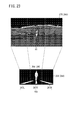
- FIG. 21A and FIG. 21B are exemplary views of a first image acquired by imaging using an infrared camera.
- FIG. 25A to FIG. 25C are schematic explanatory views illustrating a method for evaluating the degree of risk from the moving direction of the monitoring object.
- FIG. 26A and FIG. 26B are schematic explanatory views illustrating a method for evaluating the risk level from the predicted trajectory of the vehicle. It is an illustration figure of the image which respectively displayed the information regarding the 1st image shown in FIG. 21B on a general purpose monitor and MID.
- FIGS. 1 to 11 are referred to with respect to the first embodiment
- FIGS. 12 to 17B are referred to with respect to the modifications
- FIGS. 18 to 27 are referred to with respect to the second embodiment.
- FIG. 1 is a block diagram showing a configuration of a vehicle periphery monitoring device 10 according to the first embodiment.
- FIG. 2 is a schematic perspective view of the vehicle 12 in which the vehicle periphery monitoring device 10 is incorporated.
- FIG. 3 is a diagram showing a view of the vehicle 12 as viewed from the driver side.
- FIG. 3 shows a situation where the vehicle 12 is traveling on a road in a country where it is decided that the vehicle as a whole travels on the right side.
- the vehicle 12 is shown as a left-hand drive vehicle. Instead, the same configuration can be adopted even for a right-hand drive vehicle.
- the vehicle periphery monitoring device 10 includes left and right infrared cameras 16L and 16R, a vehicle speed sensor 18, a yaw rate sensor 20 (turning direction detection sensor), and an electronic control device (hereinafter referred to as “ECU22”). ), A speaker 24, a general-purpose monitor 26 (first display unit), and an MID 28 (Multi-Information Display).
- the infrared cameras 16L and 16R are imaging devices that image the periphery of the vehicle 12, and function as imaging means.
- a stereo camera is configured by combining two infrared cameras 16L and 16R.
- the infrared cameras 16L and 16R have a characteristic that the higher the temperature of the subject, the higher the output signal level (the luminance increases).
- the infrared cameras 16 ⁇ / b> L and 16 ⁇ / b> R are disposed on the front bumper portion of the vehicle 12 at positions that are substantially symmetrical with respect to the vehicle width direction center portion of the vehicle 12.
- the two infrared cameras 16L and 16R are fixed so that their optical axes are parallel to each other and the heights from both road surfaces are equal.
- the vehicle speed sensor 18 detects the vehicle speed V [km / h] of the vehicle 12 and outputs it to the ECU 22.
- the yaw rate sensor 20 detects the yaw rate Yr [° / sec] of the vehicle 12 and outputs it to the ECU 22.
- ECU22 controls the vehicle periphery monitoring apparatus 10, and has the input-output part 30, the calculating part 32, and the memory
- Each signal from the infrared cameras 16L and 16R, the vehicle speed sensor 18 and the yaw rate sensor 20 is supplied to the ECU 22 via the input / output unit 30.
- An output signal from the ECU 22 is output to the speaker 24, the general-purpose monitor 26 and the MID 28 via the input / output unit 30.
- the input / output unit 30 includes an A / D conversion circuit (not shown) that converts an input analog signal into a digital signal.
- the calculation unit 32 performs calculations based on the signals from the infrared cameras 16L and 16R, the vehicle speed sensor 18, and the yaw rate sensor 20, and generates signals for the speaker 24, the general-purpose monitor 26, and the MID 28 based on the calculation results.
- the calculation unit 32 includes a binarization function 40, a biological extraction function 42, an attention level evaluation function 44 (attention level evaluation unit), a speaker control function 45, a general-purpose monitor control function 46, and an MID control function 48.
- Each function 40, 42, 44, 45, 46, 48 is realized by executing a program stored in the storage unit 34.
- the program may be supplied from the outside via a wireless communication device (mobile phone, smartphone, etc.) not shown.
- the binarization function 40 binarizes the grayscale image 72 (FIG. 4) acquired by one of the infrared cameras 16L and 16R (in this embodiment, the left infrared camera 16L), and binarizes the image (not shown). ) Is generated.
- the living body extraction function 42 uses the grayscale image 72 and the binarized image to extract a living body such as a human or an animal (monitoring target; also simply referred to as a target) in these images.
- the attention level evaluation function 44 evaluates the level of attention of the living body for the vehicle 12 when at least one living body is detected.
- the speaker control function 45 controls the speaker 24 such as causing the speaker 24 to output an alarm sound.
- the general-purpose monitor control function 46 controls the general-purpose monitor 26 such as displaying a grayscale image 72 on the general-purpose monitor 26.
- the MID control function 48 controls the MID 28 such as displaying a mark indicating a living body such as a person (human) or an animal such as an icon (hereinafter referred to as “biological icon”) on the MID 28.
- the MID control function 48 has a boundary line setting function 50 (boundary line setting part), a sub area selection function 52 (area selection part), and an icon display function 54. Details of the functions 50, 52, and 54 will be described later.
- the storage unit 34 includes an imaging signal converted into a digital signal, a RAM (Random Access Memory) that stores temporary data used for various arithmetic processes, and a ROM (Read Only Memory) that stores an execution program, a table, a map, or the like. ) Etc.
- a RAM Random Access Memory
- ROM Read Only Memory
- the speaker 24 outputs an alarm sound or the like in response to a command from the ECU 22.
- the speaker 24 is provided on the dashboard 60 (FIG. 3) (however, the speaker 24 is not shown in FIG. 3).
- a speaker provided in an audio device or navigation device (not shown) may be used as the speaker 24.
- the general-purpose monitor 26 can display a color image or a monochrome image, and includes, for example, a liquid crystal panel, an organic EL (Electro-Luminescence), or an inorganic EL panel. As shown in FIGS. 2 and 3, the general-purpose monitor 26 is disposed at a predetermined portion of the dashboard 60, specifically, at a portion on the right side with respect to the position where the handle 64 is disposed.
- FIG. 4 is a diagram showing an example of a display screen of the general-purpose monitor 26.
- a gray scale image 72 captured by the left infrared camera 16 ⁇ / b> L is displayed in the display area of the general-purpose monitor 26 (hereinafter referred to as “first display area 70” or “display area 70”).
- the highlighted display generated by the general-purpose monitor control function 46 can be added to the gray scale image 72. That is, as shown in FIG. 4, an emphasis frame 76 is displayed on an image portion from which a living body such as a human being or an animal is extracted (object image portion; hereinafter referred to as “biological corresponding portion 74”). Alternatively, the living body corresponding portion 74 may be colored. Alternatively, both the display of the highlight frame 76 and the coloring of the living body corresponding portion 74 can be performed. Or the emphasis by other methods may be sufficient.
- the general-purpose monitor 26 may display the grayscale image 72 from the right infrared camera 16R instead of the grayscale image 72 from the left infrared camera 16L.
- the general-purpose monitor 26 simultaneously or switches other images, for example, various images for navigation (road maps, service information, etc.), moving image content, etc. May be displayed. Switching of each image can be performed by, for example, pressing a specific push button or setting a switching condition in advance.
- the MID 28 is a simple display device (icon display device) that visualizes and displays accompanying information at the time of driving the vehicle 12, and is simpler and less expensive than the general-purpose monitor 26 (particularly, its display panel). It is a display module. For example, a display panel having a resolution lower than that of the general-purpose monitor 26 (for example, one that operates in a non-interlaced manner) can be used as the MID 28.
- the MID 28 is provided on the dashboard 60 (or in the instrument panel 62) near the upper side of the instrument panel 62.
- the MID 28 is disposed at a position where a driver as a passenger can visually recognize the MID 28 through a gap above the handle 64. As a result, the driver can view the MID 28 with the face facing forward of the vehicle 12.
- FIG. 5 is a diagram showing an example of the display screen of MID28.
- the display area of MID 28 (hereinafter referred to as “second display area 80” or “display area 80”) includes an image including various icons corresponding to the grayscale image 72 (hereinafter referred to as “icon image 82”). .) Is displayed.
- a road icon 84 indicating a road in the traveling direction of the vehicle 12 is displayed below the display area 80.
- the road icon 84 includes three lines, that is, lines 84L, 84C, and 84R in order from the left.
- the width between the lines 84 ⁇ / b> L and 84 ⁇ / b> R is narrower toward the upper side of the display area 80 that recalls a distant position. That is, the display of the road icon 84 allows the driver to think of the road shape when the straight road ahead is viewed from the driver's seat.
- a human icon 86 indicating a pedestrian existing around the vehicle 12 can be displayed above the display area 80.
- the human icon 86 can be displayed in three places (that is, the left side, the center, and the right side) of the display area 80 (see FIGS. 6 and 8).
- an icon indicating another living body for example, an animal icon indicating an animal may be displayed.
- the MID 28 may display the fuel consumption of the vehicle 12, the current time, information on the instrument panel 62, and the like instead of displaying the various icons (the road icon 84, the human icon 86, and the animal icon). Switching of each piece of information (image) can be performed, for example, by pressing a specific push button or by setting a switching condition in advance.
- FIG. 6 is a diagram showing a display relationship between the general-purpose monitor 26 and the MID 28.
- the grayscale image 72 is referred to as three regions in the vehicle width direction (hereinafter referred to as “first subregions 90L, 90C, 90R”, and collectively referred to as “first subregion 90”).
- first subregions 90L, 90C, 90R regions in the vehicle width direction
- first boundary lines 92L and 92R boundary lines of the first sub-regions 90
- first boundary lines 92 are included in the actual grayscale image 72. There are no virtual lines, they are fixed and do not change.
- the first boundary line 92 may have a shape along the lane (a cross-section) like the road icon 84 of MID28.
- the icon image 82 is divided into three regions in the vehicle width direction (hereinafter referred to as “second sub regions 100L, 100C, 100R” and collectively referred to as “second sub region 100”). To do.
- the boundary lines of the second sub-regions 100 in the icon image 82 (hereinafter referred to as “second boundary lines 102L and 102R”, collectively referred to as “second boundary lines 102”) are included in the actual icon image 82. There are no virtual lines, they are fixed and do not change.
- the second boundary lines 102L and 102R are associated with the first boundary lines 92L and 92R, respectively. Similar to the first boundary line 92, the second boundary line 102 may have a shape along the lane (a cross-section) like the road icon 84 of the MID 28.
- the first sub-region 90 (hereinafter referred to as “first living-body sub-region”) to which the living body corresponding portion 74 in the gray scale image 72 belongs is determined, and the second sub region 100 of the icon image 82 in the MID 28.
- a biological icon human icon 86, animal icon, etc.
- second biological existence sub-region is displayed.
- each mark such as the human icon 86
- the presence / absence information of the monitoring target (living body) in each first sub-region 90 is visualized.
- the number of biological icons to be displayed is increased from 1 to 2 (details will be described later).
- FIG. 7 is a flowchart showing an outline of the operation of the vehicle periphery monitoring apparatus 10.
- step S1 the infrared cameras 16L and 16R image the periphery of the vehicle 12.
- step S ⁇ b> 2 the ECU 22 acquires a grayscale image 72 by A / D converting signals from the infrared cameras 16 ⁇ / b> L and 16 ⁇ / b> R.
- step S3 the ECU 22 executes binarization processing. In the binarization process, the grayscale image 72 is binarized to obtain a binarized image (not shown).
- step S4 the ECU 22 extracts the living body corresponding portion 74 from the acquired binarized image and the grayscale image 72. Since the living body is hotter than its surroundings, the portion corresponding to the living body (biological corresponding portion 74) in the binarized image and the grayscale image 72 has high brightness. Therefore, it is possible to extract the biometric corresponding portion 74 by searching for a pixel region having a luminance equal to or higher than a predetermined threshold in the binarized image and the grayscale image 72.
- both the binarized image and the grayscale image 72 simply identifies the presence of the living body using the binarized image, and then acquires detailed information about the living body using the grayscale image 72. It is to do.
- processing for example, the one described in JP-A-2003-284057 can be used.
- the biometric part 74 may be extracted using only one of the binarized image and the grayscale image 72.
- step S5 the ECU 22 displays on the general-purpose monitor 26 a grayscale image 72 in which the biological body corresponding portion 74 is emphasized.
- the highlighting is performed, for example, by displaying at least one of the display of the highlight frame 76 (FIG. 4) and the coloring of the living body corresponding portion 74.
- step S6 the ECU 22 specifies the first sub-region 90 by setting the first boundary line 92 (FIG. 6) in the grayscale image 72 or the binarized image.
- the first boundary line 92 is set so as to be equally divided into three along the horizontal direction.
- step S7 the ECU 22 determines the first sub area 90 (first living body sub area) to which the living body corresponding portion 74 belongs.
- the two first sub-regions 90 sandwiching the first boundary line 92 are determined as the first sub-region 90 to which the biological corresponding part 74 belongs. There is.
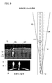
- FIGS. 8 to 11 are diagrams for explaining a method of specifying the first sub-region 90 (first biological presence sub-region) to which the living body corresponding portion 74 belongs. That is, FIG. 8 is a diagram illustrating a positional relationship between the vehicle 12 and the person 110 when the person 110 is far away, an example of the gray scale image 72 of the general-purpose monitor 26, and an example of the icon image 82 of the MID 28.
- FIG. 9 is a diagram illustrating a positional relationship between the vehicle 12 and the person 110 when the person 110 is nearby, an example of the gray scale image 72 of the general-purpose monitor 26, and an example of the icon image 82 of the MID 28.
- FIG. 8 is a diagram illustrating a positional relationship between the vehicle 12 and the person 110 when the person 110 is far away, an example of the gray scale image 72 of the general-purpose monitor 26, and an example of the icon image 82 of the MID 28.
- FIG. 9 is a diagram illustrating a positional relationship between the vehicle 12 and the person 110 when
- FIG. 10 is a diagram illustrating a positional relationship between the vehicle 12 and the person 110 when the vehicle speed V is low (during low-speed traveling), an example of the gray scale image 72 of the general-purpose monitor 26, and an example of the icon image 82 of the MID 28.
- FIG. 11 is a diagram showing a positional relationship between the vehicle 12 and the person 110 when the vehicle speed V is high (during high speed traveling), an example of the gray scale image 72 of the general-purpose monitor 26, and an example of the icon image 82 of the MID 28. 8 to 11, ⁇ indicates the image angle of view of the infrared camera 16L.
- step S8 the ECU 22 determines the second sub-region 100 (second biological sub-region) corresponding to the first biological sub-region.
- step S9 the ECU 22 displays a living body icon (human icon 86 or the like) indicating a living body in the second living body existence sub-region determined in step S8. Note that when the possibility of contact between the vehicle 12 and the living body is high, a warning sound may be emitted from the speaker 24.
- the determination as to whether or not the biological corresponding portion 74 is on the first boundary line 92 is performed based on the position of the biological corresponding portion 74 at the present time (current calculation cycle). Is not limited to this. For example, based on the movement vector of the person 110 (biological corresponding part 74) or the position on the gray scale image 72, the first sub-region 90 in which the person 110 (biological corresponding part 74) is likely to move in the future is defined as the first biological area. It can also be an existing sub-region. This makes it possible to call the driver more accurately.
- the movement vector for example, if the biological corresponding portion 74 exists in the central first sub-region 90C and the movement vector is directed leftward, the central first sub-region 90C and the left first sub-region 90L. Select. Further, if the biometric part 74 is present in the center first sub-region 90C and the movement vector is directed to the right, the center first sub-region 90C and the right first sub-region 90R are selected.
- the central first sub-region 90C and the left first sub-region 90L are selected. To do. If the living body corresponding portion 74 exists on the right side of the center first sub-region 90C, the center first sub-region 90C and the right first sub-region 90R are selected.
- the position on the movement vector or the gray scale image 72 is used to correct the position of the living body corresponding portion 74 used by the processing using the first boundary line 92 described above and the possibility of contact with the vehicle 12 described above. You can also For example, when the movement vector of the biological corresponding part 74 is directed to the left, the coordinates moved to the left side by a predetermined number of pixels from the position (current position) where the biological corresponding part 74 exists are displayed on the first boundary line 92. It may be determined whether or not there is.
- the degree of caution is the possibility of misrecognition by which an occupant of the vehicle 12 can misrecognize the position of a monitored object such as the person 110 by visually recognizing the display of the mark. If determined to be high, a plurality of biological icons (human icons 86) are simultaneously assigned to the MID 28 in correspondence with the first sub-region 90 where at least a part of the monitoring target exists and the first sub-region 90 adjacent thereto. indicate.
- “high possibility of misidentification” means, for example, (1) when the biological corresponding part 74 exists on the first boundary line 92, and (2) before and after the biological corresponding part 74 straddles the first boundary line 92. (3) When the possibility that the person 110 contacts the vehicle 12 is high (for example, when the person 110 is near the vehicle 12 or when the vehicle speed V is high).
- step S6 of FIG. 7 the ECU 22 displays the captured image 134, which is a grayscale image, in the central range including the traveling direction of the vehicle 12 within the imaging range in front of the vehicle 12 (see FIG. 13A and the like) by the infrared camera 16R.
- the captured image 134 is a grayscale image
- the central range including the traveling direction of the vehicle 12 within the imaging range in front of the vehicle 12 (see FIG. 13A and the like) by the infrared camera 16R.
- the captured image 134 includes a central region 154C corresponding to the central range including the traveling direction of the vehicle 12 in the imaging range in front of the vehicle 12, and a left region 154L corresponding to the left range on the left side of the central range.
- the left and right left boundary lines 151L and 151R of the central region 154C are divided into three sub-regions, the right region 154R corresponding to the right region on the right side of the central region.
- the section shown in FIG. 12 for the captured image 134 shows an initial setting section, and the initial setting area section is a section that is equally divided into three in the left-right direction of the captured image 134.
- the left boundary line 151L and the right boundary line 151R are used for generating the icon image 144, and are not displayed on the actual captured image 134 of the general-purpose monitor 26.
- Each data for generating the captured image 134 is luminance data of each pixel constituting the captured image 134. Whether the pixel group constituting the object image belongs to the left region 154L, the central region 154C, and the right region 154R depends on whether each pixel of each pixel group is within the left region 154L, the central region 154C, and the right region 154R. Judgment is made based on which region it belongs to.
- the left and right ends of the captured image 134 are determined by a left defining line 161L and a right defining line 161R that define a horizontal range of the left and right viewing angle ⁇ of the infrared camera 16R. That is, only the object existing inside the left defining line 161L and the right defining line 161R is captured by the infrared camera 16R and converted into the captured image 134. Objects existing outside the left defining line 161L and the right defining line 161R are excluded from the captured image 134.
- the central viewing angle ⁇ is defined inside the left and right viewing angles ⁇ , and the left and right sides are defined by the middle left defining line 166L and the middle right defining line 166R.
- the middle left defining line 166L and the middle right defining line 166R define the left boundary line 151L and the right boundary line 151R of the captured image 134. That is, the image portion of the thing within the central viewing angle ⁇ is displayed in the central region 154C of the captured image 134.
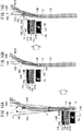
- the positions of the animal icons 157 with respect to the road icon 145 are left, center, and right in order from left to right.
- the road icon 145 and the animal icon 157 are arranged in a lower and upper relationship in the icon image 144, respectively.
- the road icon 145 is composed of a total of three lines, a left and right line, and a center line, and the width of the left and right lines is narrower toward the upper side, which looks far away, corresponding to the vehicle front view from the driver's seat. It has become.
- the animal icon 157 is displayed on the left side with respect to the left line of the road icon 145 that rises to the left as the left position.
- the animal icon 157 is displayed on the extension of the center line of the road icon 145 as the center position.
- the animal icon 157 is displayed on the right side with respect to the right line of the road icon 145 that rises to the left as the right position.
- the three icon images 144 in the lower part of FIG. 12 are displayed in the MID 28 when the animal image portion 149 (object image portion) in the captured image 134 belongs to the left region 154L, the center region 154C, and the right region 154R, respectively. Is displayed.
- a plurality of animal icons 157 corresponding to the plurality of objects are displayed in the icon image 144 according to the position in the vehicle width direction of each monitoring object. Displayed.
- a plurality of biological image portions belong to the same area, only one biological icon may be displayed on the MID 28 at a position corresponding to the area.
- the biological icon tends to be displayed at the center position in the MID 28. Since the position of the living body that is within the distance of the alerting is more uncertain when the vehicle 12 actually approaches the living body, the position of the living body becomes uncertain. The driver can be alerted.
- the living body image portion size in the captured image 134 is less than a predetermined threshold value, so that it is not extracted from the vehicle 12.
- the living body icon is not displayed on the icon image 144 of the MID 28 even if it exists inside the central viewing angle ⁇ .
- the distance from the vehicle 12 to the living body is calculated based on the parallax of the infrared cameras 16R and 16L with respect to the living body.
- the driver looks at the MID 28 and knows that the animal 160 exists ahead if the animal icon 157 is displayed in the icon image 144 of the MID 28. Then, with respect to the position of the animal 160 in the vehicle width direction of the vehicle 12, the animal 160 moves from the left and right direction position of the animal icon 157 to the road icon 145 in the MID 28 without moving from the MID 28 to the general-purpose monitor 26. It is possible to determine in which range the left side and the right side exist.
- the possibility of contact with the vehicle 12 is higher than that in the left range or the right range on both sides of the central range.
- the biometric icon is in the center position (second icon image 144 from the left in the lower part of FIG. 12) in the icon image 144, the left or right position (first or the first from the left in the lower part of FIG. 12) It is considered that the attention is increased more than when it is in the third icon image 144).
- the area division in the first embodiment is divided into three equal divisions as the initial setting division. In contrast, various improvements can be made.
- FIG. 14 is a flowchart of a process for adjusting the region segmentation based on the position in the left-right direction of the animal icon 157 in the icon image 144 according to the turning of the vehicle 12. Note that the initial setting division need not be divided into three equal divisions.
- the central region 154C may be wider or narrower than the left region 154L and the right region 154R as the initial setting division.
- step S11 the ECU 22 performs initial setting classification on the captured image 134 which is an image for the general-purpose monitor 26. That is, the left and right viewing angles ⁇ are equally divided into left, center and right angle segments, and the captured image 134 is divided into three equal parts in the left and right directions by the left boundary line 151L and the right boundary line 151R. The region is divided into a region 154C and a right region 154R.
- step S12 the ECU 22 checks whether or not the vehicle 12 is turning right. If the vehicle 12 is turning right, the ECU 22 proceeds to step S13. If not turning right, the ECU 22 skips step S13 and proceeds to step S14. It can be determined from the output of the yaw rate sensor 20 whether the vehicle 12 is currently traveling straight, turning right, or turning left.
- step S13 the ECU 22 shifts the left boundary line 151L in the captured image 134 to the left by a predetermined amount.
- the reason why the left boundary line 151L and the right boundary line 151R are shifted according to the turning direction of the vehicle 12 will be described with reference to FIGS. 15A to 15C.
- the vehicle 12 is traveling on the straight path portion before entering the right curve portion of the road image portion 140 (see FIG. 12).
- the classification of the captured image 134 when the vehicle 12 is traveling straight is set to the initial setting classification.
- the animal 160 exists in the vicinity of the center line of the left and right viewing angle ⁇ and is within the central viewing angle ⁇ .
- the animal image portion 149 is displayed in the center region 154C, and in the icon image 144, the animal icon 157 is displayed at the center position.
- FIGS. 15B and 15C illustrate a display mode of the captured image 134 and the icon image 144 when the vehicle 12 enters the right curve portion of the road image portion 140 where the animal 160 exists and turns right. ing.
- FIG. 15B shows a display mode when the area division in the captured image 134 is not changed as the initial setting division
- FIG. 15C shows the area division in the captured image 134 changed from the initial setting division (see step S11). This is the display mode when
- the horizontal distance between the object 12 near the end of the road 131 and the vehicle 12 tends to be larger when the vehicle 12 is traveling on a curved road than when the vehicle 12 is traveling on a straight road. Accordingly, as shown in FIG. 15B, when the vehicle 12 is turning right, the area segmentation in the captured image 134 is left as the initial segmentation in a straight line as shown in FIG. 15A. In spite of being on the road 131, it exits to the left from the middle left defining line 166L. Thus, in the captured image 134, the animal image portion 149 of the animal 160 belongs to the left region 154L, and in the icon image 144, the animal 160 is displayed as an object outside the road 131 by the animal icon 157 at the left position. The displayed position is different from the actual position of the animal 160 with respect to the road 131.
- step S13 the process of step S13 is performed, so that the middle left defining line 166L is shifted to the left as the outside in the turning direction by an angle q as shown in FIG. In the left-right direction, is inside the middle left defining line 166L.
- the left boundary line 151L is shifted to the left by the dimension Q on the captured image 134, and the position of the animal image portion 149 in the captured image 134 is not changed, but in the icon image 144, the animal 160 Is displayed at the left position as the animal icon 157 of the object on the road 131.
- the driver can correctly recognize the position of the animal 160 with respect to the road 131 in the vehicle width direction even during turning.
- step S14 it is checked whether the vehicle 12 is turning left. If the vehicle 12 is turning left, the process proceeds to step S15. Accordingly, while the vehicle 12 is traveling straight, the captured image 134 is a left region 154L, a center region 154C, and a right region 154R that are initially set. In step S15, the right boundary line 151R in the captured image 134 is shifted to the right by a predetermined amount.
- 15A to 15C describe the left shift of the left boundary line 151L when the vehicle 12 turns right, the significance of the right shift of the right boundary line 151R when the vehicle 12 turns left in step S15. Is the same.
- FIG. 16 is a flowchart of a process for adjusting the region division based on the horizontal position of the human icon 136 in the icon image 144 according to the vehicle speed V.
- step S ⁇ b> 21 the ECU 22 performs initial setting classification on the captured image 134 that is an image for the general-purpose monitor 26. Since this is the same as the above-described first improved example (step S11 in FIG. 14), description thereof is omitted.
- step S22 the ECU 22 checks whether or not the vehicle speed V is greater than or equal to a threshold value. If the vehicle speed V is greater than or equal to the threshold value, the ECU 22 proceeds to step S23, and if less than the threshold value, ends the vehicle speed correspondence classification process. In step S23, the ECU 22 shifts the left boundary line 151L and the right boundary line 151R outward in the left-right direction.
- the threshold shown in FIG. 16 (see step S22) is set to 60 [km / h], for example.
- 30 [km / h] shown in FIG. 17A is an example of the vehicle speed V being less than the threshold value (at low vehicle speed)
- 70 [km / h] shown in FIG. 17B is an example of the vehicle speed V being above the threshold value (at high vehicle speed). It is.
- the central viewing angle ⁇ 2 in FIG. 17B is the value of the central viewing angle ⁇ when widened with respect to the central viewing angle ⁇ 1 at the time of the initial setting division, and ⁇ 2> ⁇ 1.
- the left boundary line 151L and the right boundary line 151R at the time of low vehicle speed are set at positions corresponding to the central viewing angle ⁇ 1 at the time of the initial setting division.
- the dimension between the left boundary line 151L and the right boundary line 151R is a corresponding to the central viewing angle ⁇ 1 in the converted dimension in the captured image 134 on the general-purpose monitor 26.
- the human image portion 133 (object image portion) in the captured image 134 belongs to the left region 154L, the human icon 136 is displayed in the left position in the icon image 144.
- the dimension between the left boundary line 151L and the right boundary line 151R at the high vehicle speed corresponds to the central viewing angle ⁇ 2 in the converted dimension in the captured image 134 on the general-purpose monitor 26 (b ( b> a).
- the human image portion 133 belongs to the central region 154C in the captured image 134, the human icon 136 is displayed at the central position in the icon image 144.
- step S23 the left boundary line 151L between the center area 154C and the left area 154L and the right boundary line 151R between the center area 154C and the right area 154R are set to the left area 154L side and the right area, respectively. Displace to 154R side.
- a biological image portion such as the human image portion 133 displayed as belonging to the left region 154L or the right region 154R in the MID 28 during low speed traveling is assumed to belong to the central region 154C in the MID 28 during high speed traveling. Is displayed. Therefore, at the time of high speed traveling, the distance from the vehicle 12 to the living body when the driver is alerted can be increased to prevent the alerting from being delayed.
- the classification has two stages of a and b, but may be switched to three or more stages according to the vehicle speed V, or between the left boundary line 151L and the right boundary line 151R.
- the dimensions may be continuously changed according to the vehicle speed V.
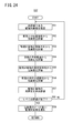
- FIG. 18 is a block diagram illustrating a configuration of the vehicle periphery monitoring device 210 according to the second embodiment.
- the vehicle periphery monitoring device 210 includes an infrared camera 16R, 16L, a vehicle speed sensor 18, a yaw rate sensor 20, a speaker 24, a general-purpose monitor 26, a MID 28 (see the vehicle periphery monitoring device 10 in FIG. 1), the brake sensor 19, and image processing.
- a unit 214 is further provided.
- the brake sensor 19 detects a brake pedal operation amount (hereinafter referred to as a brake operation amount Br) by the driver and outputs the detected amount to the image processing unit 214.
- a brake pedal operation amount Br hereinafter referred to as a brake operation amount Br
- An image processing unit 214 that controls the vehicle periphery monitoring device 210 includes an A / D conversion circuit (not shown) that converts an input analog signal into a digital signal, a CPU 214c (central processing unit) that executes various arithmetic processes, and an image processing unit.
- a storage unit 214m for storing various data to be stored, a driving signal for the speaker 24, a display signal for the general-purpose monitor 26, and a display signal for the MID 28 are further provided.
- the CPU 214c includes an object detection unit 240, a position calculation unit 242 (more specifically, a first position calculation unit 244, a second position calculation unit 246, and an actual position calculation unit 248), an attention level evaluation unit 250 (more In detail, it includes a single unit evaluation unit 252 and a comparative evaluation unit 254.), a display mark determination unit 256, and the like.
- FIG. 19A is a front view of the general-purpose monitor 26, and FIG. 19B is a front view of the MID 28.
- a rectangular first display area 260 that is long in the horizontal direction is provided on substantially the entire surface of the general-purpose monitor 26 shown in FIG. 19A.
- the state which displayed the 1st image 262 based on the imaging signal output from the infrared camera 16L in the 1st display area 260 is represented.
- a rectangular second display region 264 that is long in the horizontal direction is provided on substantially the entire surface of the MID 28 shown in FIG. 19B.
- This figure shows a state where a second image 266 obtained by extracting only a predetermined feature portion from the first image 262 and appropriately deforming it is displayed in the second display area 264.
- a road icon 268 is displayed below the second display area 264.
- the road icon 268 includes three lines and lines 267L, 267C, and 267R in order from the left.
- the vehicle periphery monitoring device 210 according to the second embodiment is basically configured as described above.
- step S31 the image processing unit 214 obtains an image signal at the current time by imaging the periphery of the vehicle 12 that is running using the infrared cameras 16R and 16L.
- the infrared camera 16R (16L) outputs an imaging signal of 30 frames per second continuously or intermittently.
- step S32 the image processing unit 214 supplies the imaging signal of one of the infrared cameras 16R and 16L, here the infrared camera 16L, to the general-purpose monitor 26 side. Then, the general-purpose monitor 26 displays the current first image 270 (or 272) in the first display area 260 (see FIG. 19A). Note that the general-purpose monitor 26 can display various images in addition to the first images 270 and 272 according to settings by an operation unit (not shown). If another image (video) is being displayed, this step is omitted.
- a first image 270 shown in FIG. 21A represents a state in which a human body part H1 (actually one human) as the object image portion is present in the road surface region Rd (actually on the road surface). . Further, in the first image 272 shown in FIG. 21B, the above-described human body part H1 exists in the road surface region Rd, and the human body part H2 (in reality, another human) as the object image part is the road surface. This represents a state existing at the edge (in reality, the road shoulder) of the region Rd.
- the object detection unit 240 detects the monitoring object from the image area represented by the imaging signal.
- monitoring objects include humans, various animals (specifically, mammals such as deer, horses, sheep, dogs and cats, birds, etc.), artificial structures (specifically, utility poles, guardrails, Wall). Note that various known methods may be applied to the detection algorithm, and it is preferable to select an appropriate method according to the type of the monitoring object.
- the first position calculation unit 244 calculates the position or existence range (hereinafter referred to as the first position) of each monitoring object in the first display area 260.
- the first position the position or existence range of each monitoring object in the first display area 260.
- step S35 the second position calculation unit 246 calculates the position of each monitoring object in the second display area 264 (hereinafter referred to as the second position).
- the second position The correspondence between the first position in the first display area 260 and the second position in the second display area 264 will be described below with reference to FIG.
- the first display area 260 in the general-purpose monitor 26 is equally divided into three sub-areas, a left area 274, a central area 276, and a right area 278 in order from the left.
- the second display area 264 in the MID 28 has three positions, a left position 284, a center position 286, and a right position 288 defined in order from the left.
- the left area 274 is associated with the left position 284, the center area 276 is associated with the center position 286, and the right area 278 is associated with the right position 288.
- the division of the first display area 260 various forms can be adopted without being limited to the example of FIG.
- the number of divisions may be two or four or more, and the size of the central region 276 may be larger (or smaller) than the left region 274 and the right region 278.
- the first display area 260 may be divided into a shape along the lane (that is, a letter C).
- step S36 the object detection unit 240 determines whether or not a plurality of monitoring objects are detected from the detection result in step S33.
- the image processing unit 214 displays the second image 266 (see FIG. 19B) or the second image 289 (see FIG. 23).
- a signal is supplied to the MID 28 side.
- the MID 28 displays the current second image 289 in the second display area 264.
- the display mark determination unit 256 determines the form (for example, shape, color, etc.) of the mark to be displayed on the MID 28.
- the display mark determination unit 256 displays the normal display color (for example, It is determined that a human icon that is white) is to be placed at the center position 286 (see the figure).
- a white human icon 290 is displayed at the approximate center of the second display area 264.
- an icon simulating the shape of the monitored object as the mark to be displayed, the driver can grasp the type at a glance.
- the type of the monitoring object is an animal, an animal icon may be used.
- the second image 289 corresponds to an image that visualizes the presence / absence information (type, presence / absence and number) of the monitoring target.
- each mark is displayed at a position (left position 284, center position 286, and right position 288) that matches the arrangement tendency of the three sub areas (left area 274, center area 276, and right area 278).
- step S39 the image processing unit 214 determines whether or not the vehicle 12 may come into contact with the monitoring target. If it is determined that there is no possibility of contact, the process returns to step S31, and steps S31 to S38 are sequentially repeated.
- step S40 the vehicle periphery monitoring device 210 provides the driver with information indicating the possibility of contact by generating an alarm sound through the speaker 24, for example. . Thereby, the avoidance operation of the driver of the vehicle 12 can be urged.
- Step S37 By the way, returning to step S36 in FIG. 20, if the number of objects to be monitored is 2 or more, the process once proceeds to step S37. For example, as shown in FIG. 21B, a case is assumed in which one monitoring object exists in the center region 276 and the right region 278 (see FIG. 22).
- the attention level evaluation unit 250 evaluates the possibility of contact of the monitored object with the vehicle 12 (hereinafter, also referred to as “risk level”).
- risk level the possibility of contact of the monitored object with the vehicle 12
- the risk evaluation method in step S37 will be described in detail with reference to the flowchart of FIG.
- step S51 the attention level evaluation unit 250 designates one monitoring object that has not been evaluated. With respect to the monitoring target specified here, the single unit evaluation unit 252 evaluates the current degree of risk in consideration of various states (through steps S52 to S57 described later).
- the single unit evaluation unit 252 evaluates the risk of contact with the monitored object from the positional relationship with the vehicle 12.
- the actual position calculation unit 248 uses a known technique such as triangulation from a pair of imaging signals from the infrared cameras 16R and 16L to monitor a target (for example, a human body corresponding to the human body part H1). And the actual distance from the vehicle 12 is calculated. Then, the unit evaluation unit 252 evaluates that the risk of contact with the monitoring object is high when the distance to the vehicle 12 is short. On the other hand, when the distance to the vehicle 12 is long, it is evaluated that the risk of contact with the monitored object is low.
- step S53 the single unit evaluation unit 252 evaluates the risk of contact with the monitored object from the moving direction of the monitored object.
- FIG. 25A to FIG. 25C are schematic explanatory views illustrating a method for evaluating the degree of risk from the moving direction of the monitored object. It is assumed that the first pedestrian existing on the road surface crosses the road surface and the second pedestrian walks along the road shoulder. That is, the human body part H1 shown in FIG. 25A (first image 272) changes to the arrow MV1 as time passes, in other words, as it transitions to FIG. 25B (first image 272a) and FIG. 25C (first image 272b). Move relative to In addition, the human body part H2 illustrated in FIG. 25A relatively moves toward the arrow MV2 as time elapses (transitions to FIGS. 25B and 25C). That is, MV1 represents a movement vector (movement amount per unit time) of the first pedestrian, and MV2 represents a movement vector (movement amount per unit time) of the second pedestrian.
- the single unit evaluation unit 252 evaluates the risk of contact with the monitoring target according to the movement vector (specifically, the direction). For example, since the movement vector MV1 in the human body part H1 is substantially parallel to the horizontal direction of the first image 272, the single body evaluation unit 252 estimates that the human body part H1 is a crossing pedestrian and contacts the monitoring object. Assess the risk is high. On the other hand, since the movement vector MV2 in the human body part H2 is inclined by a predetermined angle or more with respect to the horizontal direction of the first image 272, the single body evaluation unit 252 estimates that the human body part H2 is not a crossing pedestrian and Assess that the risk of contact with objects is low.
- the movement vector specifically, the direction
- step S54 the single unit evaluation unit 252 evaluates the risk of contact with the monitored object from the predicted trajectory of the vehicle 12.
- virtual lines P1 and P2 illustrated by alternate long and short dash lines are drawn on the same first image 272 along the traveling direction (arrow direction) of the vehicle 12, respectively.
- the virtual lines P1 and P2 represent the predicted trajectory of the vehicle 12.
- the single unit evaluation unit 252 predicts that there is a risk of contact with the first pedestrian (human body part H1) if this driving state is continued, and evaluates that the risk of contact with the monitoring object is high.
- the single unit evaluation unit 252 predicts that there is no risk of contact with the second pedestrian (human body part H2) even if the driving state is continued, and evaluates that the risk of contact with the monitoring object is low.
- the single unit evaluation unit 252 predicts that there is a risk of contact with the second pedestrian (human body part H2) if this driving state is continued, and evaluates that the risk of contact with the monitoring object is high.
- the single unit evaluation unit 252 predicts that there is no possibility of coming into contact with the first pedestrian (human body part H1) even if this driving state is continued, and evaluates that the risk of contact with the monitoring object is low.
- the single unit evaluation unit 252 evaluates the risk of contact with the monitoring target from the ease of discovery of the monitoring target by the driver. Specifically, a state in which it is difficult for the driver to find an object to be monitored is assumed in advance, and the unit evaluation unit 252 has a risk level regardless of whether or not the driver has actually found it under this state. Is highly appreciated. For example, when the size of the detection site is small, the amount of movement (movement vector) is small, the shape of the detection site is different from normal, and the like. In addition, as a specific example in which the shape of the detection site is normal, a case where the user is walking, a case where the user is running, a case where he is stopped, and the like are assumed. Moreover, as a specific example in which the shape of the detection part is different from the normal case, a case where the person is crouching or a person who is lying is assumed.
- the driver may discover the monitoring object. Have difficulty.
- a gray scale image acquired by the infrared cameras 16R, 16L, etc. it can be determined based on the difference in luminance between the two.
- a color image acquired by a color camera or the like it is possible to discriminate based on a color difference between the two in a color space such as CIERGB and CIELAB.
- the single unit evaluation unit 252 evaluates the risk of contact with the monitored object from the recognition of the presence of the vehicle 12 in the monitored object. Specifically, a state in which the presence of the vehicle 12 cannot be recognized by the monitoring target is assumed in advance, and the single unit evaluation unit 252 does not depend on whether or not the monitoring target is actually recognized under this state. Highly evaluate the risk level. For example, it is possible to estimate whether or not the vehicle 12 is in the field of view of the monitoring object by detecting the posture of the monitoring object (for example, the face direction in the case of a human body). In this case, what is necessary is just to evaluate a high risk with respect to the vehicle 12 in order of a back surface, sideways, and a front.
- the orientation of the face can be detected with high accuracy from the luminance (the on-pixel presence ratio) in the binary image of the head. This is because when the human body faces the vehicle 12, the area of the face background (on pixel) increases, and when the human body turns his back to the vehicle 12, the area of the hair (off pixel) increases. Because. Similarly, an intermediate state other than the front and back surfaces (sideways and diagonally) may be estimated.
- the situation judgment ability and / or behavior predictability of the monitoring object may be estimated and reflected in the risk evaluation. For example, it is possible to further determine whether or not the monitoring target is determined to be a human body based on the shape and behavior of the detection site and whether it is an elderly person (or a child), and highly evaluate these risks.
- step S57 the single unit evaluation unit 252 comprehensively evaluates the risk level of the monitoring target specified in step S51.
- the degree of risk may be either a numerical value or a level, and the data format is not limited. Further, the specific gravity (weighting) of each evaluation value evaluated and calculated in steps S52 to S56 may be arbitrarily changed. For example, in principle, the degree of risk is evaluated from the positional relationship with the vehicle 12 (see step S52). If there are a plurality of monitoring objects having a high level of risk, other evaluation items (step S53) To S56) may be considered together.
- step S53 the accuracy of the risk assessment is increased by taking into account the movement prediction of the monitored object.
- step S54 the accuracy of the risk evaluation is increased by taking into account the predicted trajectory of the vehicle 12 as well.
- step S55 the evaluation from the viewpoint of the driver is further added, and the accuracy of the risk evaluation is increased.
- step S56 the evaluation from the viewpoint of the monitoring object is further added, and the accuracy of the risk evaluation is increased.
- the first image 272 or other input information for example, vehicle speed V, brake operation amount Br, yaw rate Yr, GPS (Global Positioning System), or distance information acquired from ranging means. Etc. can be used in various ways.
- step S58 the attention level evaluation unit 250 determines whether or not the evaluation for each monitoring object has been completed. If it is determined that the process has been completed, the process returns to step S51, and thereafter, steps S51 to S57 are sequentially repeated until all the evaluations are completed. On the other hand, if it is determined that the process is completed, the process proceeds to the next step (S59).
- the comparative evaluation unit 254 selects at least one monitoring object having a high level of risk among the plurality of monitoring objects.
- This selection result may be only one or two or more.
- the human body part H1 is selected from the two monitoring objects (human body parts H1 and H2).
- step S37 ends.
- the MID 28 displays the current second image 291 in the second display area 264 (see FIG. 19B) (step S38).
- the display mark determination unit 256 determines the form of the mark to be displayed on the MID 28.
- the display mark determining unit 256 moves the human icon to the central position 286 ( (See the same figure).
- the display mark determination unit 256 places the human icon at the right position 288 (see the same drawing). Decide that.
- the display mark determination unit 256 displays a display color (for example, red) that makes the human icon to be placed at the center position 286 stand out more than usual. And the remaining human icons to be placed at the right position 288 are set to the normal display color (white).
- a red human icon 292 is displayed in the approximate center of the second display area 264, and a white human icon 294 is displayed on the right side.
- the driver looks at the visually highlighted red human icon 292. Then, the driver can increase alertness to the central area of the first image 272, that is, the front front of the vehicle 12 from the relative positional relationship between the human icon 292 and the first display area 260. That is, it is possible to notify the driver of the presence of a monitoring object having a relatively high attention level among the plurality of monitoring objects.
- the display method of the human icons 292 and 294 is not limited to the case where the human icon 294 is displayed in a more conspicuous form than usual, and the other human icon 292 is not conspicuous than usual. You may take the method of displaying with a form, or the method which combined both.
- the display form may include a change in shape (for example, size) and provision of visual effects (for example, blinking display, rocking display, etc.). Any means can be used as long as a visual difference can be provided.
- the MID 28 determines the attention level evaluation unit 250.
- the display forms of the human icons 292 and 294 are changed according to the degree of risk evaluated by the above. Thereby, the driver can be notified of the difference in the attention level among a plurality of monitoring objects, which is convenient for driving support.
- the risk level (attention level) is the possibility that the monitoring target can contact the vehicle 12.
- the vehicle 12 is assumed to be a four-wheeled vehicle (see FIG. 2), but the vehicle 12 on which the vehicle periphery monitoring devices 10 and 210 are mounted is not limited to this. For example, it can be mounted on a two-wheeled vehicle (including a bicycle), a tricycle, or a six-wheeled vehicle.
- the vehicle periphery monitoring devices 10 and 210 are mounted on the vehicle 12. However, if the surrounding monitoring target object is detected and this is notified to the user, it may be mounted on another moving body. it can. Examples of the moving body include a ship and an aircraft.
- the two infrared cameras 16L and 16R are used as the imaging means for imaging the surroundings of the vehicle 12, but the present invention is not limited to this as long as the surroundings of the vehicle 12 can be imaged.
- the imaging means may be a compound eye (stereo camera) or a monocular (one camera).
- a camera color camera that mainly uses light having a wavelength in the visible light region may be used, or both may be provided.
- the general-purpose monitor 26 is used to display the grayscale image 72 from the infrared camera 16L.
- the present invention is not limited to this as long as it displays an image captured by the imaging unit.
- the emphasis frame 76 was displayed on the gray scale image 72 displayed on the general purpose monitor 26
- the gray scale image 72 from the infrared camera 16L is directly added to the general purpose monitor 26 without attaching an emphasis display. It may be displayed.
- a relatively versatile display device that operates in a non-interlaced manner is used as the MID 28 to display a biometric icon (mark).
- the present invention is not limited to this, and an indicator that displays only a biometric icon.
- a plurality of (for example, three) can be used instead of MID28.
- a head-up display (HUD) as shown in FIG. 2 of Japanese Patent Application No. 2004-364112 can be used in place of the MID 28.
- both the general-purpose monitor 26 and the MID 28 are used, but a configuration using only the MID 28 is also possible.
- the gray scale image 72 acquired by the infrared camera 16L is used for displaying on the MID 28.
Landscapes
- Engineering & Computer Science (AREA)
- Multimedia (AREA)
- Mechanical Engineering (AREA)
- Physics & Mathematics (AREA)
- General Physics & Mathematics (AREA)
- Signal Processing (AREA)
- Theoretical Computer Science (AREA)
- Traffic Control Systems (AREA)
- Closed-Circuit Television Systems (AREA)
Abstract
Priority Applications (4)
| Application Number | Priority Date | Filing Date | Title |
|---|---|---|---|
| US14/346,053 US20140226015A1 (en) | 2011-09-21 | 2012-09-21 | Apparatus for monitoring surroundings of vehicle |
| EP12834549.3A EP2759999B1 (fr) | 2011-09-21 | 2012-09-21 | Appareil de surveillance de l'environnement d'un véhicule |
| CN201280044711.8A CN103797530B (zh) | 2011-09-21 | 2012-09-21 | 车辆周围监测装置 |
| JP2013534767A JP5616531B2 (ja) | 2011-09-21 | 2012-09-21 | 車両周辺監視装置 |
Applications Claiming Priority (6)
| Application Number | Priority Date | Filing Date | Title |
|---|---|---|---|
| JP2011206620 | 2011-09-21 | ||
| JP2011-206620 | 2011-09-21 | ||
| JP2011224528 | 2011-10-12 | ||
| JP2011-224528 | 2011-10-12 | ||
| JP2011238600 | 2011-10-31 | ||
| JP2011-238600 | 2011-10-31 |
Publications (1)
| Publication Number | Publication Date |
|---|---|
| WO2013042767A1 true WO2013042767A1 (fr) | 2013-03-28 |
Family
ID=47914527
Family Applications (1)
| Application Number | Title | Priority Date | Filing Date |
|---|---|---|---|
| PCT/JP2012/074229 WO2013042767A1 (fr) | 2011-09-21 | 2012-09-21 | Appareil de surveillance de l'environnement d'un véhicule |
Country Status (5)
| Country | Link |
|---|---|
| US (1) | US20140226015A1 (fr) |
| EP (1) | EP2759999B1 (fr) |
| JP (1) | JP5616531B2 (fr) |
| CN (1) | CN103797530B (fr) |
| WO (1) | WO2013042767A1 (fr) |
Cited By (7)
| Publication number | Priority date | Publication date | Assignee | Title |
|---|---|---|---|---|
| JP2015181216A (ja) * | 2014-03-06 | 2015-10-15 | パナソニックIpマネジメント株式会社 | 表示制御装置および表示制御プログラム |
| JP2016048547A (ja) * | 2014-08-27 | 2016-04-07 | トヨタ自動車株式会社 | ヘッドアップディスプレイ用の空間情報の生成 |
| JP2016070915A (ja) * | 2014-09-30 | 2016-05-09 | 富士重工業株式会社 | 車両の視線誘導装置 |
| WO2017221663A1 (fr) * | 2016-06-20 | 2017-12-28 | パナソニックIpマネジメント株式会社 | Système d'affichage vidéo |
| WO2018003532A1 (fr) * | 2016-06-29 | 2018-01-04 | 京セラ株式会社 | Appareil de détection et d'affichage d'objet, corps mobile et procédé de détection et d'affichage d'objet |
| JP2019214348A (ja) * | 2018-06-14 | 2019-12-19 | クラリオン株式会社 | 物体認識装置 |
| JP2020145564A (ja) * | 2019-03-05 | 2020-09-10 | 株式会社デンソーテン | 画像処理装置および画像処理方法 |
Families Citing this family (21)
| Publication number | Priority date | Publication date | Assignee | Title |
|---|---|---|---|---|
| US10703299B2 (en) * | 2010-04-19 | 2020-07-07 | SMR Patents S.à.r.l. | Rear view mirror simulation |
| JP5760090B2 (ja) * | 2011-09-28 | 2015-08-05 | 本田技研工業株式会社 | 生体認識装置 |
| JP2016001464A (ja) | 2014-05-19 | 2016-01-07 | 株式会社リコー | 処理装置、処理システム、処理プログラム、及び、処理方法 |
| JP6550881B2 (ja) * | 2014-07-14 | 2019-07-31 | 株式会社リコー | 立体物検出装置、立体物検出方法、立体物検出プログラム、及び移動体機器制御システム |
| US10131276B2 (en) * | 2014-09-30 | 2018-11-20 | Subaru Corporation | Vehicle sightline guidance apparatus |
| EP3007099B1 (fr) * | 2014-10-10 | 2022-12-07 | Continental Autonomous Mobility Germany GmbH | Système de reconnaissance d'image pour véhicule et procédé correspondant |
| US9588340B2 (en) | 2015-03-03 | 2017-03-07 | Honda Motor Co., Ltd. | Pedestrian intersection alert system and method thereof |
| US9847022B2 (en) * | 2015-07-22 | 2017-12-19 | Ace/Avant Concrete Construction Co., Inc. | Vehicle detection system and method |
| US9950619B1 (en) | 2015-09-30 | 2018-04-24 | Waymo Llc | Occupant facing vehicle display |
| CN105216715A (zh) * | 2015-10-13 | 2016-01-06 | 湖南七迪视觉科技有限公司 | 一种汽车驾驶员视觉辅助增强系统 |
| JP6613795B2 (ja) * | 2015-10-16 | 2019-12-04 | 株式会社デンソー | 表示制御装置および車両制御装置 |
| JP6493196B2 (ja) | 2015-12-17 | 2019-04-03 | 株式会社デンソー | 制御装置、制御方法 |
| WO2017126221A1 (fr) * | 2016-01-19 | 2017-07-27 | 日産自動車株式会社 | Procédé de commande de dispositif d'affichage et dispositif d'affichage |
| JP6353881B2 (ja) * | 2016-08-25 | 2018-07-04 | 株式会社Subaru | 車両の表示装置 |
| JP6551377B2 (ja) * | 2016-12-15 | 2019-07-31 | トヨタ自動車株式会社 | 車両用注意喚起装置 |
| EP3584120B1 (fr) * | 2017-02-17 | 2021-04-14 | Sumitomo Heavy Industries, Ltd. | Système de surveillance d'environnement de machine de travail |
| JP7203512B2 (ja) | 2018-05-17 | 2023-01-13 | 株式会社小糸製作所 | センサデータ生成装置 |
| DE102019117689A1 (de) * | 2019-07-01 | 2021-01-07 | Bayerische Motoren Werke Aktiengesellschaft | Verfahren und Steuereinheit zur Darstellung einer Verkehrssituation durch Ausblenden von Verkehrsteilnehmer-Symbolen |
| CN112428989B (zh) * | 2020-10-30 | 2022-03-11 | 惠州华阳通用电子有限公司 | 一种车辆控制方法 |
| CN115553780B (zh) * | 2022-12-06 | 2023-03-21 | 深圳市心流科技有限公司 | 注意力评估方法、设备及存储介质 |
| CN115581457B (zh) * | 2022-12-13 | 2023-05-12 | 深圳市心流科技有限公司 | 注意力评估方法、装置、设备及存储介质 |
Citations (11)
| Publication number | Priority date | Publication date | Assignee | Title |
|---|---|---|---|---|
| JP2001114048A (ja) * | 1999-10-20 | 2001-04-24 | Matsushita Electric Ind Co Ltd | 車載運転支援情報表示装置 |
| JP2003284057A (ja) | 2002-01-18 | 2003-10-03 | Honda Motor Co Ltd | 車両周辺監視装置 |
| JP2004364112A (ja) | 2003-06-06 | 2004-12-24 | Honda Motor Co Ltd | 車両周辺表示装置 |
| JP2007069806A (ja) * | 2005-09-08 | 2007-03-22 | Clarion Co Ltd | 車両用障害物検出装置 |
| JP2007323578A (ja) * | 2006-06-05 | 2007-12-13 | Honda Motor Co Ltd | 車両周辺監視装置 |
| JP2008026985A (ja) * | 2006-07-18 | 2008-02-07 | Toyota Motor Corp | 車載用歩行者検出装置 |
| JP2009067214A (ja) | 2007-09-12 | 2009-04-02 | Toyota Motor Corp | 障害物検知装置 |
| JP2010044561A (ja) * | 2008-08-12 | 2010-02-25 | Panasonic Corp | 乗物搭載用監視装置 |
| JP2010247621A (ja) * | 2009-04-14 | 2010-11-04 | Stanley Electric Co Ltd | 自動車の運転支援システム |
| JP2011087006A (ja) * | 2009-10-13 | 2011-04-28 | Denso Corp | 車両用表示装置 |
| JP2011091549A (ja) * | 2009-10-21 | 2011-05-06 | Toyota Motor Corp | 車両用夜間視界支援装置 |
Family Cites Families (7)
| Publication number | Priority date | Publication date | Assignee | Title |
|---|---|---|---|---|
| US6993159B1 (en) * | 1999-09-20 | 2006-01-31 | Matsushita Electric Industrial Co., Ltd. | Driving support system |
| JP4055656B2 (ja) * | 2003-05-30 | 2008-03-05 | トヨタ自動車株式会社 | 衝突予測装置 |
| JP4650079B2 (ja) * | 2004-11-30 | 2011-03-16 | 日産自動車株式会社 | 物体検出装置、および方法 |
| JP4353162B2 (ja) * | 2005-09-26 | 2009-10-28 | トヨタ自動車株式会社 | 車輌周囲情報表示装置 |
| JP2009098956A (ja) * | 2007-10-17 | 2009-05-07 | Mazda Motor Corp | 車両用運転支援装置 |
| US8095276B2 (en) * | 2008-10-15 | 2012-01-10 | Autoliv Asp, Inc. | Sensor system including a confirmation sensor for detecting an impending collision |
| US8704653B2 (en) * | 2009-04-02 | 2014-04-22 | GM Global Technology Operations LLC | Enhanced road vision on full windshield head-up display |
-
2012
- 2012-09-21 CN CN201280044711.8A patent/CN103797530B/zh active Active
- 2012-09-21 EP EP12834549.3A patent/EP2759999B1/fr active Active
- 2012-09-21 US US14/346,053 patent/US20140226015A1/en not_active Abandoned
- 2012-09-21 JP JP2013534767A patent/JP5616531B2/ja active Active
- 2012-09-21 WO PCT/JP2012/074229 patent/WO2013042767A1/fr active Application Filing
Patent Citations (11)
| Publication number | Priority date | Publication date | Assignee | Title |
|---|---|---|---|---|
| JP2001114048A (ja) * | 1999-10-20 | 2001-04-24 | Matsushita Electric Ind Co Ltd | 車載運転支援情報表示装置 |
| JP2003284057A (ja) | 2002-01-18 | 2003-10-03 | Honda Motor Co Ltd | 車両周辺監視装置 |
| JP2004364112A (ja) | 2003-06-06 | 2004-12-24 | Honda Motor Co Ltd | 車両周辺表示装置 |
| JP2007069806A (ja) * | 2005-09-08 | 2007-03-22 | Clarion Co Ltd | 車両用障害物検出装置 |
| JP2007323578A (ja) * | 2006-06-05 | 2007-12-13 | Honda Motor Co Ltd | 車両周辺監視装置 |
| JP2008026985A (ja) * | 2006-07-18 | 2008-02-07 | Toyota Motor Corp | 車載用歩行者検出装置 |
| JP2009067214A (ja) | 2007-09-12 | 2009-04-02 | Toyota Motor Corp | 障害物検知装置 |
| JP2010044561A (ja) * | 2008-08-12 | 2010-02-25 | Panasonic Corp | 乗物搭載用監視装置 |
| JP2010247621A (ja) * | 2009-04-14 | 2010-11-04 | Stanley Electric Co Ltd | 自動車の運転支援システム |
| JP2011087006A (ja) * | 2009-10-13 | 2011-04-28 | Denso Corp | 車両用表示装置 |
| JP2011091549A (ja) * | 2009-10-21 | 2011-05-06 | Toyota Motor Corp | 車両用夜間視界支援装置 |
Non-Patent Citations (1)
| Title |
|---|
| See also references of EP2759999A4 |
Cited By (12)
| Publication number | Priority date | Publication date | Assignee | Title |
|---|---|---|---|---|
| JP2015181216A (ja) * | 2014-03-06 | 2015-10-15 | パナソニックIpマネジメント株式会社 | 表示制御装置および表示制御プログラム |
| JP2016048547A (ja) * | 2014-08-27 | 2016-04-07 | トヨタ自動車株式会社 | ヘッドアップディスプレイ用の空間情報の生成 |
| JP2016070915A (ja) * | 2014-09-30 | 2016-05-09 | 富士重工業株式会社 | 車両の視線誘導装置 |
| WO2017221663A1 (fr) * | 2016-06-20 | 2017-12-28 | パナソニックIpマネジメント株式会社 | Système d'affichage vidéo |
| JPWO2017221663A1 (ja) * | 2016-06-20 | 2019-04-25 | パナソニックIpマネジメント株式会社 | 映像表示システム |
| US11019315B2 (en) | 2016-06-20 | 2021-05-25 | Panasonic Intellectual Property Management Co., Ltd. | Video display system |
| WO2018003532A1 (fr) * | 2016-06-29 | 2018-01-04 | 京セラ株式会社 | Appareil de détection et d'affichage d'objet, corps mobile et procédé de détection et d'affichage d'objet |
| JPWO2018003532A1 (ja) * | 2016-06-29 | 2019-05-16 | 京セラ株式会社 | 物体検出表示装置、移動体及び物体検出表示方法 |
| US11195026B2 (en) | 2016-06-29 | 2021-12-07 | Kyocera Corporation | Object detection and display apparatus, moveable body, and object detection and display method |
| JP2019214348A (ja) * | 2018-06-14 | 2019-12-19 | クラリオン株式会社 | 物体認識装置 |
| JP7244221B2 (ja) | 2018-06-14 | 2023-03-22 | フォルシアクラリオン・エレクトロニクス株式会社 | 物体認識装置 |
| JP2020145564A (ja) * | 2019-03-05 | 2020-09-10 | 株式会社デンソーテン | 画像処理装置および画像処理方法 |
Also Published As
| Publication number | Publication date |
|---|---|
| JPWO2013042767A1 (ja) | 2015-03-26 |
| JP5616531B2 (ja) | 2014-10-29 |
| CN103797530A (zh) | 2014-05-14 |
| EP2759999B1 (fr) | 2016-07-27 |
| EP2759999A4 (fr) | 2015-04-15 |
| US20140226015A1 (en) | 2014-08-14 |
| CN103797530B (zh) | 2015-09-09 |
| EP2759999A1 (fr) | 2014-07-30 |
Similar Documents
| Publication | Publication Date | Title |
|---|---|---|
| JP5616531B2 (ja) | 車両周辺監視装置 | |
| JP5639283B2 (ja) | 車両周辺監視装置 | |
| US10198950B2 (en) | Parking support method and parking support device | |
| JP5706874B2 (ja) | 車両の周辺監視装置 | |
| JP5577398B2 (ja) | 車両の周辺監視装置 | |
| JP2018195301A (ja) | 制御装置及び制御方法 | |
| JP5774770B2 (ja) | 車両周辺監視装置 | |
| JP4173902B2 (ja) | 車両周辺監視装置 | |
| JP5480925B2 (ja) | 車両周辺監視装置 | |
| JP4528283B2 (ja) | 車両周辺監視装置 | |
| JP2002319091A (ja) | 後続車両認識装置 | |
| JP2007249841A (ja) | 画像認識装置 | |
| JP2006338594A (ja) | 歩行者認識装置 | |
| JP5192007B2 (ja) | 車両の周辺監視装置 | |
| JP5604011B2 (ja) | 車両周辺監視装置 | |
| WO2018212090A1 (fr) | Dispositif de commande et procédé de commande | |
| JP2012058999A (ja) | 車両周辺監視装置 | |
| JP5703192B2 (ja) | 車両周辺監視装置 | |
| JP5430633B2 (ja) | 車両周辺監視装置 | |
| JP5383246B2 (ja) | 車両の周辺監視装置 | |
| JP2013095375A (ja) | 車両周辺監視装置 | |
| US20240112570A1 (en) | Moving body prediction device, learning method, traffic safety support system, and storage medium | |
| JP2014074951A (ja) | 車両周辺監視装置 |
Legal Events
| Date | Code | Title | Description |
|---|---|---|---|
| 121 | Ep: the epo has been informed by wipo that ep was designated in this application |
Ref document number: 12834549 Country of ref document: EP Kind code of ref document: A1 |
|
| ENP | Entry into the national phase |
Ref document number: 2013534767 Country of ref document: JP Kind code of ref document: A |
|
| REEP | Request for entry into the european phase |
Ref document number: 2012834549 Country of ref document: EP |
|
| WWE | Wipo information: entry into national phase |
Ref document number: 2012834549 Country of ref document: EP |
|
| WWE | Wipo information: entry into national phase |
Ref document number: 14346053 Country of ref document: US |
|
| NENP | Non-entry into the national phase |
Ref country code: DE |