WO2013031077A1 - 情報処理システム及び情報処理方法 - Google Patents
情報処理システム及び情報処理方法 Download PDFInfo
- Publication number
- WO2013031077A1 WO2013031077A1 PCT/JP2012/004510 JP2012004510W WO2013031077A1 WO 2013031077 A1 WO2013031077 A1 WO 2013031077A1 JP 2012004510 W JP2012004510 W JP 2012004510W WO 2013031077 A1 WO2013031077 A1 WO 2013031077A1
- Authority
- WO
- WIPO (PCT)
- Prior art keywords
- specimen
- display
- area
- image data
- unit
- Prior art date
- Legal status (The legal status is an assumption and is not a legal conclusion. Google has not performed a legal analysis and makes no representation as to the accuracy of the status listed.)
- Ceased
Links
Images


Classifications
-
- G—PHYSICS
- G02—OPTICS
- G02B—OPTICAL ELEMENTS, SYSTEMS OR APPARATUS
- G02B21/00—Microscopes
- G02B21/36—Microscopes arranged for photographic purposes or projection purposes or digital imaging or video purposes including associated control and data processing arrangements
- G02B21/365—Control or image processing arrangements for digital or video microscopes
-
- G—PHYSICS
- G06—COMPUTING OR CALCULATING; COUNTING
- G06F—ELECTRIC DIGITAL DATA PROCESSING
- G06F3/00—Input arrangements for transferring data to be processed into a form capable of being handled by the computer; Output arrangements for transferring data from processing unit to output unit, e.g. interface arrangements
- G06F3/01—Input arrangements or combined input and output arrangements for interaction between user and computer
- G06F3/048—Interaction techniques based on graphical user interfaces [GUI]
- G06F3/0484—Interaction techniques based on graphical user interfaces [GUI] for the control of specific functions or operations, e.g. selecting or manipulating an object, an image or a displayed text element, setting a parameter value or selecting a range
- G06F3/0485—Scrolling or panning
-
- G—PHYSICS
- G06—COMPUTING OR CALCULATING; COUNTING
- G06T—IMAGE DATA PROCESSING OR GENERATION, IN GENERAL
- G06T7/00—Image analysis
- G06T7/30—Determination of transform parameters for the alignment of images, i.e. image registration
- G06T7/33—Determination of transform parameters for the alignment of images, i.e. image registration using feature-based methods
- G06T7/337—Determination of transform parameters for the alignment of images, i.e. image registration using feature-based methods involving reference images or patches
-
- G—PHYSICS
- G06—COMPUTING OR CALCULATING; COUNTING
- G06V—IMAGE OR VIDEO RECOGNITION OR UNDERSTANDING
- G06V10/00—Arrangements for image or video recognition or understanding
- G06V10/40—Extraction of image or video features
- G06V10/42—Global feature extraction by analysis of the whole pattern, e.g. using frequency domain transformations or autocorrelation
- G06V10/422—Global feature extraction by analysis of the whole pattern, e.g. using frequency domain transformations or autocorrelation for representing the structure of the pattern or shape of an object therefor
- G06V10/426—Graphical representations
-
- G—PHYSICS
- G06—COMPUTING OR CALCULATING; COUNTING
- G06V—IMAGE OR VIDEO RECOGNITION OR UNDERSTANDING
- G06V20/00—Scenes; Scene-specific elements
- G06V20/60—Type of objects
- G06V20/69—Microscopic objects, e.g. biological cells or cellular parts
- G06V20/695—Preprocessing, e.g. image segmentation
-
- G—PHYSICS
- G06—COMPUTING OR CALCULATING; COUNTING
- G06T—IMAGE DATA PROCESSING OR GENERATION, IN GENERAL
- G06T2207/00—Indexing scheme for image analysis or image enhancement
- G06T2207/10—Image acquisition modality
- G06T2207/10056—Microscopic image
-
- G—PHYSICS
- G06—COMPUTING OR CALCULATING; COUNTING
- G06T—IMAGE DATA PROCESSING OR GENERATION, IN GENERAL
- G06T2207/00—Indexing scheme for image analysis or image enhancement
- G06T2207/30—Subject of image; Context of image processing
- G06T2207/30004—Biomedical image processing
- G06T2207/30024—Cell structures in vitro; Tissue sections in vitro
-
- G—PHYSICS
- G09—EDUCATION; CRYPTOGRAPHY; DISPLAY; ADVERTISING; SEALS
- G09G—ARRANGEMENTS OR CIRCUITS FOR CONTROL OF INDICATING DEVICES USING STATIC MEANS TO PRESENT VARIABLE INFORMATION
- G09G2380/00—Specific applications
- G09G2380/08—Biomedical applications
Definitions
- the present technology relates to an information processing system and an information processing method for controlling display of image data obtained by a microscope in the fields of medical treatment, pathology, living organisms, materials, and the like.
- Patent Document 1 an image optically obtained by a microscope is digitized by a video camera equipped with a CCD (Charge-Coupled Device), and the digital signal is input to a control computer system to be monitored. Is visualized. The pathologist performs an examination or the like by looking at the image displayed on the monitor (see, for example, paragraphs [0027] and [0028] and FIG. 5 of Patent Document 1).
- CCD Charge-Coupled Device
- the section When taking an image of a section using an optical microscope, the section is placed on a glass slide to prepare a slide.
- a glass slide When imaging a large number of sections, etc. For the reason, a plurality of sections may be placed on one glass slide.
- the entire glass slide on which a plurality of sections are placed is imaged in this way, only an integral image of the entire glass slide is obtained, and an image of each individual section cannot be obtained. For this reason, it is difficult to distinguish and handle images of individual sections, which may impair convenience for the user.
- each of a plurality of sections placed on a glass slide is individually imaged, an image of each section can be obtained, so that each section image can be distinguished and handled.
- the images of the individual sections individually captured are associated with each other. It is difficult to handle and may impair convenience for the user.
- an object of the present technology is to provide an information processing apparatus and an information processing method that are more convenient for the user.
- the information processing system is a slide in which a plurality of sections obtained by cutting one specimen in the same direction are discretely placed.
- An image acquisition unit for acquiring image data obtained by photographing a plurality of sample regions having the same shape including the individual sections in the acquired image data, and the image data of each of the sample regions Between the specimen regions based on the stored position information, a detection unit that calculates position information relatively indicating the position in the coordinate space, a first storage unit that stores the calculated position information, and And a control unit for switching the display.
- the control unit switches the display between the specimen regions based on the position information that is metadata. Thereby, the control unit skips the region other than the sample region, even though the image data acquired by the acquisition unit is image data obtained by photographing the slide itself on which a plurality of sections are placed.
- the display can be switched between areas.
- the first storage unit records the sample area as position information that is metadata, so that display switching between the sample areas can be performed efficiently and at high speed. Furthermore, using the position information that is the metadata, even when a plurality of specimen regions span the image data of a plurality of slides, as in the case of sequentially displaying a plurality of specimen regions detected from one image data, Display processing can be performed efficiently.
- the information processing system further includes a generation unit that generates reduced data with a reduced resolution of the image data, and the detection unit detects the plurality of specimen regions from the reduced data, thereby The plurality of specimen regions may be detected.
- the generation unit can detect the sample region efficiently and at high speed.
- the control unit receives the specification of the sample region to be displayed in the acquired image data and a range in the sample region, the specification is performed.
- the display area is calculated as a display area, and when the display area is at the end of the sample area, an instruction to move the display area outside the end is received from the user,
- the display may be switched to the display of the adjacent specimen region in the cutting order based on the stored position information.
- the control unit moves the display area outside the end.
- the display may be switched to the display of the adjacent specimen region in the cutting order while fixing the position in the other axial direction.
- the acquisition unit acquires image data obtained by photographing a slide in which a plurality of sections obtained by cutting one specimen in the same direction are placed in a row and discretely, and the control unit When the calculated display area is at the end of the sample area in the alignment direction of the plurality of sample areas in the coordinate space of the image data, the display area is moved in the alignment direction before the end.
- a display area of the specimen area of the movement destination may be calculated based on the stored position information.
- the information processing system detects a feature point of each of the plurality of specimen regions, calculates an offset amount of each feature point coordinate in the coordinate space of the specimen region, and calculates the calculated offset amount.
- a second storage unit that stores the stored position information and the stored offset amount when receiving an instruction from the user to jump the display region to another specimen region. Based on the above, the display area of the jump destination may be calculated so that the positions of the feature points in the display area before and after the jump match.
- the control unit determines the position of the feature point in the display region before and after the jump. Can be matched. Further, by using the metadata for setting the display area, the corresponding display area can be accurately calculated, and the display process can be performed efficiently and at high speed.
- the alignment unit calculates an affine transformation matrix for matching the detected feature points in the plurality of specimen regions in a display space, and calculates the offset amount based on the calculated affine transformation matrix. Also good.
- the offset amount in the biaxial direction can be calculated by using the affine transformation matrix. As a result, the corresponding display areas before and after the jump can be calculated more accurately.
- control unit When the control unit receives designation of a plurality of specimen regions to be displayed in the acquired image data from a user, the control unit divides the display space into a number of display spaces equal to the number of the designated plurality of specimen regions. Based on the stored position information and the stored offset amount, the plurality of display spaces are arranged so that the positions of the feature points in the specimen region displayed in the plurality of display spaces coincide with each other. The display area displayed on the screen may be calculated.
- control unit can match the positions of the feature points in the specimen regions displayed in the plurality of display spaces based on the offset amounts between the feature points included in the plurality of specimen regions as metadata. . Further, by using the metadata for setting the display area, the corresponding display area can be accurately calculated, and the display process can be performed efficiently and at high speed.
- the information processing method is obtained by photographing a slide on which a plurality of sections obtained by the obtaining unit cutting a single specimen in the same direction are discretely placed. And the detection unit detects a plurality of specimen regions having the same shape including each of the sections in the obtained image data, and each of the specimen regions in the coordinate space of the image data is detected. Position information relatively indicating the position is calculated, the first storage unit stores the calculated position information, and the control unit performs display between the specimen regions based on the stored position information. Switch.
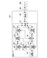
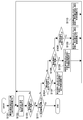
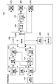
- FIG. 1 is a diagram illustrating a configuration of an information processing system according to an embodiment of the present technology.
- the information processing system 1 includes an image server 100 and one or more viewers 200A and 200B. These can be connected to each other through the network 300.
- the network 300 may be a WAN (Wide Area Network) such as the Internet or a LAN (Local Area Network).
- the network 300 may be wired or wireless.
- two viewers 200A and 30B are connected is shown here for simplicity of explanation, the number of viewers may be three or more. In this specification, when viewers are not individually specified, they are described as “viewer 200”.
- the image server 100 and the one or more viewers 200 may be configured by a typical computer, for example.
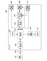
- FIG. 2 is a diagram showing a functional configuration of the image server 100 implemented using a typical computer system.
- the image server 100 includes an image acquisition unit 109 (acquisition unit), a slide image storage unit 101, a thumbnail image generation unit 110 (generation unit), a thumbnail image storage unit 102, and a specimen region detection unit 103 (detection unit). , An offset coordinate storage unit 104 (first storage unit), a feature matching unit 105, a triangle / matrix storage unit 106, a server control unit 107, and a server communication unit 108.
- Each functional unit is realized in a computer resource based on a program loaded in a RAM (Random Access Memory).
- the image acquisition unit 109 acquires an image via a network or acquires slide image data recorded on a removable recording medium, associates the slide image data with a slide ID, and slide image storage unit 101.
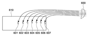
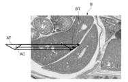
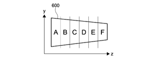
- the “slide image” refers to a glass slide on which a plurality of sections 601 to 607 obtained by cutting one specimen 600 in the same direction are placed in a row and discretely. This is an image obtained by photographing 610.
- the “slide ID” is an ID for individually identifying data of a plurality of slide images.
- “Aligned in a row” is not limited to a state in which the glass slides are linearly arranged, but means a state in which the glass slide is arranged in a direction from one end side to the other end side.
- the thumbnail image generation unit 110 generates a thumbnail image of the slide image stored in the slide image storage unit 101, and records the thumbnail image data in association with the slide ID in the thumbnail image storage unit 102.
- the “thumbnail image” is reduced data in which the resolution of the slide image data is lowered.
- the slide image storage unit 101 and the thumbnail image storage unit 102 are set to a rewritable nonvolatile memory.
- the specimen region detection unit 103 reads thumbnail image data from the thumbnail image storage unit 102, and from the read thumbnail image data, a plurality of regions (specimen regions) each including a plurality of sections placed on a glass slide. ) Is detected.
- the detection of the specimen region is performed as follows, for example. That is, the specimen region detection unit 103 recognizes a point where the brightness changes sharply in the image as the boundary of the object on the glass slide (edge extraction), and recognizes a closed curve having a size equal to or larger than the threshold as the edge (contour) of the slice. To do. Subsequently, the specimen region detection unit 103 extracts specimen regions that individually include the recognized sections from the thumbnail image data.
- the sample region detection unit 103 selects the range of the sample region so that the section is located at the approximate center of the sample region and the section is within the range of the sample region.
- Each specimen region has an arbitrary shape and size, and in this embodiment, each specimen region is rectangular.
- the specimen area detection unit 103 also calculates offset coordinates (position information) of each specimen area.
- This “offset coordinate” is information representing the position of each specimen region in the coordinate space of a slide image including a plurality of slice images.
- the “offset coordinates” are, for example, one vertex (for example, the lower left corner) of a rectangular glass slide, and an arbitrary point in each sample region (for example, one vertex of a rectangular sample region).
- the position of the lower left end is a value represented by the difference (distance) in the biaxial direction from the origin.
- the sample region detection unit 103 associates each calculated offset coordinate, the sample region number of the sample region indicated by the offset coordinate, and the metadata of the slide number of the slide image including the sample region, respectively, and offset coordinates. Records in the storage unit 104. This “number” reflects the order of section cutting, that is, the order in which sections are arranged in a direction substantially orthogonal to the cut surface, and is expressed by an integer of 1 or more, for example, and set by the specimen region detection unit 103 .
- the offset coordinate storage unit 104 is set to a rewritable nonvolatile memory.
- the specimen region detection unit 103 performs feature matching between images of a plurality of specimen regions detected from the thumbnail image data as described above. This feature matching may be performed by the same method as the feature matching by the feature matching unit 150 described later.
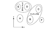
- the specimen region detection unit 103 determines the similarity between the sections A to F in a plurality of specimen regions included in one slide image based on the result of feature matching. Then, as shown in FIG. 10, the sample region detecting unit 103 is located close to the sample regions including the sections B and C having high similarity, and is close to the sample regions including the sections D and E having high similarity. Group to be located at. In the specimen region detection unit 103, as shown in FIG.
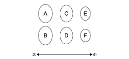
- a section A having a large area is continuous from one (for example, the root) of the specimen 600 toward a section F (for example, the tip) having a small area.
- consecutive specimen region numbers are set so that the feature point position interval is narrowed.
- the sample region detecting unit 103 determines the similarity between the sample regions at both ends of one slide image and the sample regions at both ends of another slide image. judge.
- the sample region detection unit 103 determines that slide images including a sample region having a high degree of similarity are continuous slide images, and sets consecutive slide numbers.
- the sample area detection unit 103 rewrites the slide ID recorded in the slide image storage unit 101 and the thumbnail image storage unit 102 with the set slide number.
- sample area number and the slide number may be corrected by the user using the viewer 200.
- the user uses the viewer 200 to perform the specimen.
- An area number and a slide number may be set.
- the viewer 200 may capture information input to a LIS (Laboratory Information System) and set the specimen region number and the slide number.
- LIS Laboratory Information System
- the feature matching unit 105 performs feature matching (details will be described later) between the images of the specimen regions of the slide images stored in the slide image storage unit 101. Specifically, the feature matching unit 105 reads slide image data from the slide image storage unit 101. The feature matching unit 105 reads from the offset coordinate storage unit 104 a plurality of specimen region numbers and offset coordinates associated with the slide number associated with the read slide image data. The feature matching unit 105 detects a plurality of specimen regions from the slide image based on the read offset coordinates and the size given to each specimen region in common. The feature matching unit 105 performs feature matching between the detected images of the plurality of specimen regions, and calculates a triangle and an affine transformation matrix.
- the feature matching unit 105 records the calculated triangle and affine transformation matrix data, the sample region number specifying each sample region, and the metadata of the slide number in association with each other and records them in the triangle / matrix storage unit 106.
- the triangle / matrix storage unit 106 is set to a rewritable nonvolatile memory.
- the server control unit 107 reads out the corresponding image data from the slide image storage unit 101, and supplies the image data to the viewer 200 using the server communication unit 108.
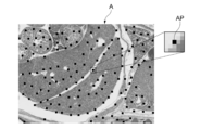
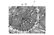
- the feature matching unit 105 uses, for example, an extraction algorithm such as a Harris algorithm, as shown in FIG. 4, from an image of an arbitrary detection area (referred to as detection area A) serving as a reference, to obtain a luminance value.
- detection area A an arbitrary detection area
- a point A point where the change in the value exceeds the threshold is extracted.
- Harris algorithm is robust to image rotation and has the advantage of not taking feature points on the gradient.
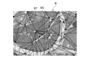
- the feature matching unit 105 uses the normalized correlation of the image to identify where each feature point in the image of the detection area A corresponds in the image of another detection area (referred to as detection area B). decide. Specifically, as shown in FIG. 5, the feature matching unit 105 sets a search area SA in the detection area B image based on the feature point AP (see FIG. 4) in the reference detection area A image. To do.
- the feature matching unit 105 searches the search area SA of the detection area B, calculates a normalized correlation between the texture pattern of the detection area B and the texture pattern of the detection area A, and obtains the highest value ( It is determined that the highest point is a corresponding point (white point in the figure) BP corresponding to the feature point (black point in the figure) AP. In the example shown in the figure, the feature matching unit 105 selects the point having the highest value of 0.98 among the values 0.04, 0.87, and 0.98 obtained by calculating the normalized correlation as the corresponding points. Judge as BP. Note that if the highest point is less than a predetermined threshold (for example, 0.90), the feature matching unit 105 determines that the feature point AP cannot be used for matching. If the number of feature points determined to be adopted does not reach a predetermined threshold value, the feature matching unit 105 has a low similarity between the detection regions A and B, so matching between the detection regions A and B Is judged to be impossible.
- a predetermined threshold for example, 0.
- the feature matching unit 105 uses, for example, a division algorithm such as the Delaunay algorithm, It is divided into a plurality of triangles with the adopted feature points (black dots in the figure) as vertices. As shown in FIG. 7, the feature matching unit 105 maintains the divided topology of the detection area A, and the image of the detection area B also corresponds to the feature points (black dots in the figure) corresponding to the adopted feature points (white dots in the figure). Is divided into a plurality of triangles having a point as a vertex.
- a division algorithm such as the Delaunay algorithm
- the feature matching unit 105 identifies the triangle AT including the display center coordinates AC of the image of the detection area A by the inside / outside determination.
- the feature matching unit 105 calculates an affine transformation matrix for converting the triangle BT in the detection area B corresponding to the triangle AT in the detection area A into the triangle AT.
- the calculated affine transformation matrix is used to calculate the coordinates (in this case, the center coordinates) of a corresponding point in another detection area based on the coordinates (for example, the center coordinates) of an arbitrary point in a certain detection area. Can do.
- the affine transformation matrix is, for example, an image of the display center coordinates AC (see FIG. 8) of the image of the specimen region A (see FIG. 6) on the image of the specimen region B.
- the position BC can be determined and used for the process of moving the display center of the screen of the specimen region B to the position BC.
- FIG. 9 is a diagram showing a functional configuration of a viewer 200 realized by using a typical computer system.
- the viewer 200 includes a viewer control unit 207 (control unit), a viewer communication unit 204, an alignment data creation unit 208 (alignment unit), an alignment data storage unit 209 (second storage unit), and a first coordinate calculation.
- Each functional unit is realized in a computer resource based on a program loaded in the RAM.
- the viewer control unit 207 performs processing such as transmitting a request to the image server 100 using the viewer communication unit 204, supplying the received data to each function unit of the viewer 200, and controlling each function unit.
- the alignment data creation unit 208 calculates an offset amount in the biaxial direction between a plurality of specimen regions in the coordinate space of the slide image based on the triangle and affine transformation matrix data obtained by feature matching. More specifically, the alignment data creation unit 208 includes a triangle including a point located at, for example, the center coordinates of a certain sample region as a reference point, and a triangle including a point corresponding to this reference point in another sample region. The offset amount in the biaxial direction of the coordinates in the coordinate space of the specimen region is calculated as alignment data. The alignment data creation unit 208 records the calculated alignment data in the alignment data storage unit 209.
- the alignment data storage unit 209 is set to a rewritable nonvolatile memory.
- the first coordinate calculation unit 203 performs processing such as calculating position information of a display area for performing an operation (discrete display) for sequentially displaying only the specimen area by skipping an area other than the specimen area.
- the second coordinate calculation unit 206 performs processing such as calculating position information of the display area for performing an operation (jump display) for sequentially displaying the corresponding areas of the specimen area.
- the “corresponding region” indicates a region in the plurality of sections that coincides in a direction substantially orthogonal to the cut surface.
- the third coordinate calculation unit 210 divides the display screen and performs processing such as calculating position information of the display region for performing an operation (synchronous display) for displaying each of the plurality of sample regions in synchronization with each other. Do.
- the display processing unit 205 outputs display data for displaying image data to the display unit 201.
- Discrete display In discrete display, a process for displaying only the sample regions in order by skipping regions other than the sample region in the slide image (regions where no sections are placed) is performed.
- FIG. 13 is a diagram showing a specific example of discrete display.
- the figure shows a first glass slide 610 and a second glass slide 620.
- these sections are placed across a plurality of glass slides.
- the first to seventh sections 601 to 607 are placed on the first glass slide 610 in this order.
- An example in which the eighth to fourteenth sections 608 to 614 are placed on the second glass slide 620 in this order is shown. Further, it is assumed that the first to fourteenth specimen regions 621 to 634 including the respective first to fourteenth sections 601 to 614 are detected.
- a rectangular area at the lower left corner of the first specimen area 621 is displayed on the display unit 201 as a display area 641.
- the user uses the input unit 202 such as a mouse to input a command for moving the image in the display area 641 up and down and left and right.
- the display area moves horizontally in the first specimen area 621 until the display area 641a at the lower right corner of the first specimen area 621 is reached (arrow).
- A When an instruction to move further to the right is input, a region where the section between the first and second sample regions 621 and 622 is not placed is skipped, and the lower left corner of the second sample region 622 is displayed.
- the display area moves to the area 641b (arrow B).
- the display area is moved to the display area 641c at the lower right corner of the seventh sample area 621, and a movement instruction in the right direction is further input.
- the display area 641d in the lower left corner of the eighth specimen area 628 of the second glass slide 620 is displayed.
- the display area moves (arrow C).
- FIG. 14 is a flowchart showing discrete display processing by the viewer 200.
- the user selects discrete display as the display mode using the input unit 202, for example.
- the viewer control unit 207 reads out the thumbnail image of the slide image recorded in the thumbnail image storage unit 102 of the image server 100 in association with the slide number using the viewer communication unit 204.
- the viewer control unit 207 causes the display processing unit 205 to generate a sample region selection screen based on the read slide number and the thumbnail image of the slide image and display the sample region selection screen on the display unit 201.
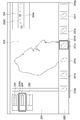
- FIG. 15 is a diagram showing a specimen region selection screen.
- the sample region selection screen 220 includes a slide tray 221, a sample region tray 222, an observation display area 223, and a display region display area 224.
- thumbnail images 230, 231, and 232 of the slide images read from the image server 100 by the viewer control unit 207 are displayed as a list.
- the thumbnail images 230, 231, and 232 of the slide images are arranged in the order of slide numbers from top to bottom.
- the user selects one thumbnail image 231 from the plurality of thumbnail images 230, 231, and 232 displayed on the slide tray 221 using the input unit 202 such as a mouse.
- the viewer control unit 207 causes the display processing unit 205 to display the selected thumbnail image 231 in a form that can be identified by a frame line (231A) or the like, and displays a thumbnail image 231C corresponding to the selected thumbnail image 231 in the display area. It is displayed in the display area 224.
- the viewer control unit 207 displays the specimen region number and the offset coordinates as metadata recorded in the offset coordinate storage unit 104 of the image server 100 in association with the slide number associated with the selected thumbnail image. Reading is performed using the unit 204. In addition, the viewer control unit 207 uses the viewer communication unit 204 for the specimen region number, the triangle, and the affine matrix as metadata recorded in the triangle / matrix storage unit 106 of the image server 100 in association with the slide number. Read out. The viewer control unit 207 sends the thumbnail images 231a to 231g of the plurality of sample regions in the selected thumbnail image 231 to the sample processing unit 205 based on the offset coordinates and slide numbers as the read metadata. 222 is displayed as a list. The thumbnail images 231a to 231g of the specimen area are arranged in order of specimen area numbers from left to right.
- the user uses the input unit 202 such as a mouse to select one thumbnail image 231d from the plurality of thumbnail images 231a to 231g displayed on the sample area tray 222.
- the selected thumbnail image 231d is displayed so as to be identified by a frame line (231B) or the like.
- an image of the specimen region of the selected thumbnail image 231d is displayed in the observation display area 223.
- an image of the entire specimen area is displayed in this way, and a part of the specimen area (display area) is displayed at an arbitrary resolution.
- the thumbnail image 231C displayed in the display area display area 224 the position of the sample area currently displayed in the observation display area 223 is displayed so as to be identified by a frame line (224a) or the like.
- the operation of selecting the slide to be displayed and the specimen region is common in discrete display, jump display, and synchronous display.
- the viewer control unit 207 detects an input to the input unit 202 by the user, and determines the slide number and sample region number of the slide and sample region to be displayed first. The viewer control unit 207 then supplies the offset coordinates associated with the slide number and specimen region number as metadata to the first coordinate calculation unit 203 that performs processing for discrete display.
- the first coordinate calculation unit 203 displays the first display based on the offset coordinates of the specimen area as metadata, the size and the initial position (for example, the lower left corner of the specimen area) given to each display area in common. The position information of the area is calculated. The size and initial position given in common to each of these display areas are recorded in a rewritable nonvolatile memory.
- the first coordinate calculation unit 203 supplies the calculated position information to the viewer control unit 207, and the viewer control unit 207 uses the viewer communication unit 204 to issue a request for acquiring an image corresponding to the display area. Send to server 100.
- the server control unit 107 of the image server 100 receives this request using the server communication unit 108 and reads out the image data of the display area included in the request from the slide image storage unit 101.
- the server control unit 107 transmits the read image data to the viewer 200 using the server communication unit 108.
- the viewer control unit 207 of the viewer 200 receives the image data of the display area using the viewer communication unit 204, and supplies the received image data of the display area to the display processing unit 205.
- the display processing unit 205 outputs display data for displaying the image data to the display unit 201 and displays the display data in the observation display area 223 of the specimen region selection screen 220 (step S101).
- the user inputs a command for moving the image in the display area displayed in the observation display area 223 up, down, left, and right using the input unit 202 such as a mouse.
- the viewer control unit 207 detects an input of a movement command to the input unit 202 by the user and supplies the detected movement command to the first coordinate calculation unit 203.
- the first coordinate calculation unit 203 calculates position information of the display area of the movement destination based on this movement command.
- the first coordinate calculation unit 203 supplies the calculated position information to the viewer control unit 207, and the viewer control unit 207 uses the viewer communication unit 204 to issue a request for acquiring an image corresponding to the display area. Send to server 100.
- step S101 the server control unit 107 of the image server 100 reads out the corresponding image data from the slide image storage unit 101 in response to a request from the viewer 200, and transmits it to the viewer 200 using the server communication unit 108. To do. Thereby, the viewer 200 acquires the image data of the display area of the movement destination, and updates the display content of the display unit 201 (step S102).
- the first coordinate calculation unit 203 determines that the display area of the movement destination has reached the boundary of the specimen area based on the calculated position information (Yes in step S103), the boundary is any end of the specimen area. It is determined whether (right end, lower end, left end, upper end) (steps S104, S105, S106).
- the first coordinate calculation unit 203 detects a rightward movement instruction from the user when the display region is at the right end of the sample region (Yes in step S104)
- the first coordinate calculation unit 203 increments the sample region number of the sample region to be displayed. To do. The sample region number obtained in this way becomes the sample region number of the sample region to be displayed next.
- the first coordinate calculation unit 203 sets the display area in the specimen area corresponding to the specimen area number obtained by the increment as follows. That is, the first coordinate calculation unit 203 maintains the Y offset between the upper end of the sample area and the upper end of the display area, and displays the display in the target sample area so that the left end of the sample area matches the left end of the display area.
- An area is set (step S107).
- the first coordinate calculation unit 203 detects a downward movement instruction from the user when the display area is at the lower end of the specimen area (Yes in step S105), the specimen area number of the specimen area to be displayed is displayed. Is incremented.
- the first coordinate calculation unit 203 sets the display area in the specimen area corresponding to the specimen area number obtained by the increment as follows. That is, the first coordinate calculation unit 203 maintains the X offset between the left end of the sample area and the left end of the display area, and displays the display in the target sample area so that the upper end of the sample area matches the upper end of the display area.
- An area is set (step S108).
- the first coordinate calculation unit 203 detects an instruction to move leftward from the user when the display area is at the left end of the specimen area (Yes in step S106), the specimen area number of the specimen area to be displayed is displayed. Is decremented.
- the first coordinate calculation unit 203 sets the display area in the specimen area corresponding to the specimen area number obtained by decrement as follows. That is, the first coordinate calculation unit 203 maintains the Y offset between the upper end of the sample area and the upper end of the display area, and displays the display in the movement destination sample area so that the right end of the sample area matches the right end of the display area. An area is set (step S109).
- the first coordinate calculation unit 203 detects an upward movement instruction from the user when the display area is at the upper end of the specimen area (No in step S106), the specimen area number of the specimen area to be displayed is displayed. Is decremented.
- the first coordinate calculation unit 203 sets the display area in the specimen area corresponding to the specimen area number obtained by decrement as follows. That is, the first coordinate calculation unit 203 maintains the X offset between the left end of the sample area and the left end of the display area, and displays the display in the movement destination sample area so that the lower end of the sample area matches the lower end of the display area.
- An area is set (step S110).
- the first coordinate calculation unit 203 sets the display area.
- the position information of the display area is supplied to the viewer control unit 207.
- the viewer control unit 207 transmits a request for acquiring an image corresponding to the display area to the image server 100 using the viewer communication unit 204.
- step S101 the server control unit 107 of the image server 100 reads out the corresponding image data from the slide image storage unit 101 in response to a request from the viewer 200, and transmits it to the viewer 200 using the server communication unit 108. To do. Thereby, the viewer 200 acquires the image data of the display area of the movement destination and updates the display content of the display unit 201.
- step S111 If the first coordinate calculation unit 203 determines that there is no specimen region to be displayed next as a result of the above calculation (Yes in step S111), the discrete display process ends.
- the information processing system 1 obtains image data obtained by photographing a slide on which a plurality of sections obtained by cutting one specimen in the same direction are discretely placed.
- the acquisition unit 109 detects a plurality of specimen regions having the same shape including individual sections in the acquired image data, and calculates position information that relatively indicates the position of the image data of each specimen region in the coordinate space.
- a sample region detection unit 103 that performs calculation, an offset coordinate storage unit 104 that stores calculated position information, and a viewer control unit 207 that switches display between sample regions based on the stored position information. .
- the viewer control unit 207 switches display between specimen regions based on position information that is metadata. As a result, the viewer control unit 207 skips the region other than the sample region, even though the image data acquired by the acquisition unit is image data obtained by photographing the slide itself on which a plurality of sections are placed. The display can be switched between the specimen regions. Further, the first storage unit records the sample area as position information that is metadata, so that display switching between the sample areas can be performed efficiently and at high speed. Furthermore, using the position information that is the metadata, even when a plurality of specimen regions span the image data of a plurality of slides, as in the case of sequentially displaying a plurality of specimen regions detected from one image data, Display processing can be performed efficiently.
- the information processing system 1 further includes a thumbnail image thumbnail image generation unit 110110 that generates reduced data with reduced resolution of image data, and the sample region detection unit 103 detects a plurality of sample regions from the reduced data. As a result, a plurality of specimen regions in the image data are detected.
- the sample region can be detected efficiently and at high speed.
- a plurality of image data of a plurality of sample areas are managed in the cutting order, and the viewer control unit 207 specifies a sample area to be displayed in the acquired image data and a range in the area.
- the range within the specified sample area is calculated as the display area, and when the display area is at the end of the sample area, an instruction to move the display area outside the end is received from the user. Then, the display is switched to the display of the adjacent specimen region in the cutting order based on the stored position information.
- the viewer control unit 207 displays the display area when the calculated display area is at the end in the one axial direction of the plurality of specimen areas in the coordinate space of the specimen data.
- the display is switched to the display of the adjacent specimen region in the cutting order while fixing the position in the other axial direction.
- the image acquisition unit 109 photographs a slide on which a plurality of sections obtained by cutting one specimen in the same direction are placed in a row and discretely.
- the acquired image data is acquired, and the viewer control unit 207 determines that the calculated display region is located at the end of the sample region in the direction of the arrangement of the plurality of sample regions in the coordinate space of the image data.
- the display area of the sample area of the movement destination is calculated based on the stored position information.
- the image acquisition unit 109 captures image data obtained by photographing a slide on which a plurality of sections obtained by cutting one specimen in the same direction are discretely placed.
- the sample region detection unit 103 detects a plurality of sample regions having the same shape including individual sections in the acquired image data, and relatively positions the image data of the individual sample regions in the coordinate space.
- the position information to be shown is calculated, the offset coordinate storage unit 104 stores the calculated position information, and the viewer control unit 207 switches the display between the sample regions based on the stored position information.
- jump display Next, jump display will be described. In the jump display, processing for sequentially displaying the corresponding areas of the specimen area is performed.
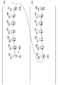
- FIG. 16 is a diagram showing a specific example of jump display.
- the first to fourteenth slices 601 to 614 are placed on the first and second glass slides 610 and 620 in this order, and the first to fourteenth slices 601 to 614 are attached.
- An example in which the first to fourteenth specimen regions 621 to 634 including the respective samples are detected is shown.
- the specimen area tray 222 (FIG. 15) on the specimen area selection screen 220 displays the first specimen area 621 currently displayed.
- a thumbnail image in the specimen region 622 on the right side of the thumbnail image is selected as the destination specimen region.
- the display area moves to the display area 642a of the second specimen area 622 (arrow D).
- the display areas 642 and 642a are at the same position in the coordinate space of the specimen areas 621 and 622 having the same shape. That is, portions that are continuous in a direction substantially orthogonal to the cut surface of the specimen are displayed as the display areas 642 and 642a.
- This movement between the specimen areas is repeated, and the display area is moved to the display area 642b of the seventh specimen area 621 (located at the same position as the display areas 642 and 642a in the coordinate space of the specimen area having the same shape). To do.
- the second glass slide 620 is moved.
- the display area located at the same position as the display area 642b in the coordinate space of the specimen area of the same shape moves to the display area 642c of the eighth specimen area 628 of the second glass slide 620 (arrow E). ).
- FIG. 17 is a flowchart showing jump display processing by the viewer 200.
- the slide and specimen region to be displayed first are selected in the same manner as the slide and specimen region to be displayed first are selected. Further, the user selects jump display as the display mode using the input unit 202, for example.
- the viewer control unit 207 supplies the slide data, specimen region number, triangle, and affine transformation matrix data as metadata to the alignment data creation unit 208.
- the alignment data creating unit 208 calculates the biaxial offset in the coordinate space of the slide image of the specimen region in all combinations of the plurality of specimen regions. More specifically, the alignment data creation unit 208 uses an affine transformation matrix to correspond to a triangle that includes a point located at, for example, the central coordinates of a certain sample region as a reference point and this reference point in another sample region. The offset in the biaxial direction on the absolute coordinate with the triangle including the point to be calculated is calculated.
- This offset becomes alignment data for adjusting the display area in one specimen area with respect to the display area in the other specimen area.
- the alignment data creation unit 208 records the calculated alignment data in the alignment data storage unit 209 (step S201). Note that this alignment data generation operation is common in jump display and synchronous display display modes.
- the viewer control unit 207 performs processing for jump display on the offset coordinates associated with the slide to be displayed and the slide number of the sample region and the sample region number selected by the user. To supply.
- the second coordinate calculation unit 206 calculates the position information of the display area to be displayed first based on the offset coordinates, the size and the initial position (for example, the lower left corner of the specimen area) commonly given to the display areas. To do. The size and initial position given in common to each of these display areas are recorded in a rewritable nonvolatile memory.
- the second coordinate calculation unit 206 supplies the calculated position information to the viewer control unit 207, and the viewer control unit 207 uses the viewer communication unit 204 to send a request for acquiring an image corresponding to the display area. Send to server 100.
- the server control unit 107 of the image server 100 receives this request using the server communication unit 108 and reads out the image data of the display area included in the request from the slide image storage unit 101.
- the server control unit 107 transmits the read image data to the viewer 200 using the server communication unit 108.
- the viewer control unit 207 of the viewer 200 receives the image data of the display area using the viewer communication unit 204, and supplies the received image data of the display area to the display processing unit 205.
- the display processing unit 205 outputs display data for displaying the image data to the display unit 201 and displays the display data in the observation display area 223 of the specimen region selection screen 220 (step S202).
- the user inputs a command for moving the image in the display area displayed in the observation display area 223 up, down, left, and right using the input unit 202 such as a mouse.
- the viewer control unit 207 detects a movement command input to the input unit 202 by the user, and supplies the detected movement command to the second coordinate calculation unit 206.
- the second coordinate calculation unit 206 calculates position information of the display area of the movement destination based on this movement command.
- the second coordinate calculation unit 206 supplies the calculated position information to the viewer control unit 207, and the viewer control unit 207 uses the viewer communication unit 204 to send a request for acquiring an image corresponding to the display area. Send to server 100.
- step S202 the server control unit 107 of the image server 100 reads out the corresponding image data from the slide image storage unit 101 in response to a request from the viewer 200, and transmits it to the viewer 200 using the server communication unit 108. To do. Thereby, the viewer 200 acquires the image data of the display area of the movement destination, and updates the display content of the display unit 201 (step S203).
- the user uses the input unit 202 to input a command for moving the display from the sample region image displayed in the observation display area 223 to another sample region image.
- a command for moving the display from the sample region image displayed in the observation display area 223 to another sample region image for example, the right or left adjacent sample region of the currently displayed sample region is selected from the plurality of thumbnail images displayed on the sample region tray 222 (FIG. 15) of the sample region selection screen 220. Is done.
- this input is performed by selecting a slide above or below the currently displayed slide from a plurality of thumbnail images displayed on the slide tray 221 (FIG. 15) of the specimen region selection screen 220.
- step S204 When the viewer control unit 207 detects an input of a movement command to the input unit 202 by the user (Yes in step S204), whether the input destination specimen region is the right side, the left side, or the destination slide is up. It is determined whether it is lower (steps S205 and S206).
- the viewer control unit 207 determines that the destination specimen region is right next or the destination slide is down (Yes in step S205), the viewer control unit 207 increments the specimen region number of the specimen region to be displayed. On the other hand, when the viewer control unit 207 determines that the destination specimen region is on the left side or the destination slide is up (Yes in step S206), the viewer control unit 207 decrements the specimen region number of the specimen region to be displayed. The sample region number obtained in this way becomes the sample region number of the destination sample region.
- the viewer control unit 207 notifies the second coordinate calculation unit 206 of the sample region number of the destination sample region and the position information of the currently displayed display region (movement source display region).
- the second coordinate calculation unit 206 reads the offset coordinates associated with the movement destination specimen area number from the offset coordinate storage unit 104.
- the second coordinate calculation unit 206 reads out from the alignment data storage unit 209 alignment data for making the destination specimen region coincide with the source specimen region in the coordinate space.
- the second coordinate calculation unit 206 matches the positions of the corresponding points in the display area of the movement source and the movement destination in the respective display areas based on the offset coordinates and the alignment data as metadata. In this manner, a display area in the movement destination specimen area corresponding to the movement source display area is set.
- a point in the display area of the movement source (for example, the center point of the display area) and a corresponding point in the display area of the movement destination may not match each other in the respective display areas.
- the second coordinate calculation unit 206 based on the alignment data, a point in the display area of the movement source and a corresponding point in the display area of the movement destination match each other in each display area. In this manner (for example, the center of the display area), the display area of the movement destination is adjusted (steps S207 and S208).
- the second coordinate calculation unit 206 calculates the position information of the display area adjusted in the above steps S207 to S208.
- the second coordinate calculation unit 206 supplies the calculated position information to the viewer control unit 207, and the viewer control unit 207 uses the viewer communication unit 204 to send a request for acquiring an image corresponding to the display area. It is transmitted to the server 100.
- step S202 the server control unit 107 of the image server 100 reads out the corresponding image data from the slide image storage unit 101 in response to a request from the viewer 200, and transmits it to the viewer 200 using the server communication unit 108. To do. Thereby, the viewer 200 acquires the image data of the display area of the movement destination and updates the display content of the display unit 201.
- step S209 When the second coordinate calculation unit 206 determines that there is no specimen region to be displayed next as a result of the above calculation (Yes in step S209), the discrete display process is terminated.
- the information processing system 1 detects the feature points of each of the plurality of specimen regions, calculates the offset amount in the coordinate space of the specimen region at the coordinates of the respective feature points, and the calculation And an alignment data storage unit 209 for storing the offset amount, and the viewer control unit 207 stores the position information stored when the instruction to jump the display region to another sample region is received from the user. Based on the offset amount, the jump destination display area is calculated so that the positions of the feature points in the display area before and after the jump match.
- the alignment data creation unit 208 sets the display region based on the offset amount between the feature points included in the plurality of specimen regions as metadata, the viewer control unit 207 performs the display in the display region before and after the jump.
- the positions of feature points can be matched.
- the corresponding display area can be accurately calculated, and the display process can be performed efficiently and at high speed.
- the alignment data creation unit 208 calculates an affine transformation matrix for matching the detected feature points in the plurality of specimen regions in the display space, and uses the calculated affine transformation matrix. Based on this, the offset amount is calculated.
- the offset amount in the biaxial direction can be calculated by using the affine transformation matrix. As a result, the corresponding display areas before and after the jump can be calculated more accurately.
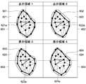
- FIG. 18 is a diagram showing a specific example of synchronous display.
- a plurality of (for example, four) sample regions 621 to 624 are selected by the user as display targets.
- the plurality of specimen regions 621 to 624 are individually assigned to display spaces 651 to 654 obtained by dividing the observation display area 223 (FIG. 15) of the specimen region selection screen 220 into a plurality of substantially equal size areas. Is displayed. More specifically, a plurality of points 621a to 624a located at the centers of the plurality of specimen regions 621 to 624 are arranged so that the positions in the display spaces 651 to 654 coincide with each other (so as to be located at the center). Sample areas 621 to 624 are displayed.
- the user uses the input unit 202 to select a slide to be displayed from the slide tray 221 (FIG. 15) on the sample region selection screen 220 displayed on the display unit 201, and from the sample region tray 222, a plurality of display targets (for example, Four) sample areas are selected.
- the viewer control unit 207 detects an input to the input unit 202 by the user, and determines a slide to be displayed, a slide number of a plurality of sample regions, and a plurality of sample region numbers. Then, the viewer control unit 207 supplies the slide number and the plurality of specimen region numbers to the third coordinate calculation unit 210 that performs processing for synchronous display.
- the viewer control unit 207 divides the observation display area 223 (FIG. 15) of the specimen region selection screen 220 as a display space into a number of display spaces equal to the number of designated (for example, four) specimen regions. Then, the viewer control unit 207 supplies coordinate information of each divided display space to the third coordinate calculation unit 210.
- the third coordinate calculation unit 210 is based on offset coordinates associated with the sample region numbers of the plurality of sample regions to be displayed and alignment data for adjusting the offset between the plurality of sample regions to be displayed.
- the display area is set so that the center points of the plurality of specimen areas match. That is, the third coordinate calculation unit 210 makes the positions in the center of the plurality of specimen regions coincide with each other in the display space based on the offset coordinates and the alignment data as metadata. Set the display area to (in the center).
- the third coordinate calculation unit 210 calculates position information of each set display area.
- the third coordinate calculation unit 210 supplies the obtained position information to the viewer control unit 207, and the viewer control unit 207 uses the viewer communication unit 204 to make a request for acquiring an image corresponding to the display area. Transmit to the image server 100.
- the server control unit 107 of the image server 100 reads the corresponding image data from the slide image storage unit 101 in response to a request from the viewer 200, and uses the server communication unit 108 to send the image data to the viewer 200.
- the viewer 200 acquires image data of a plurality of display areas and displays the image data on the display unit 201.
- the viewer control unit 207 changes the observation display area 223 (FIG. 15) of the sample region selection screen 220 displayed on the display unit 201 to an area of approximately the same size as the number of sample regions to be displayed.
- the display processing unit 205 displays a plurality of display spaces obtained by dividing the observation display area 223 (FIG. 15) of the specimen region selection screen 220 displayed on the display unit 201 into a plurality of substantially equal-sized areas.
- the image data in the display area is individually assigned and displayed.
- the viewer control unit 207 receives a plurality of sample regions to be displayed in the acquired image data from the user, and receives a plurality of sample regions in which the display space is specified. Is divided into a number equal to the number of display spaces, and based on the stored position information and the stored offset amount, the positions of the feature points in the specimen region displayed in the plurality of display spaces match. The display area displayed in a plurality of display spaces is calculated.
- the viewer control unit 207 matches the positions of the feature points in the sample areas displayed in the plurality of display spaces based on the offset amounts between the feature points included in the plurality of sample areas as metadata. Can do. Further, by using the metadata for setting the display area, the corresponding display area can be accurately calculated, and the display process can be performed efficiently and at high speed.
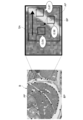
- FIG. 19 is a diagram illustrating a hardware configuration of a typical computer 400.
- the computer 400 includes a CPU (Central Processing Unit) 401, a ROM (Read Only Memory) 402, and a RAM 403.
- the computer 400 also includes an input device 404, an output device 405, a storage device 406, a media interface device 407, a network connection device 408, and a bus 409 for connecting them.
- the CPU 401 functions as an arithmetic processing unit and a control unit, and controls the overall operation of the computer 400 according to various programs.
- the ROM 402 stores programs and calculation parameters used by the CPU 401.
- the RAM 403 temporarily stores programs executed by the CPU 401, parameters that change as appropriate during the execution, and the like.
- the input device 404 includes an input means for a user to input information, such as a mouse, keyboard, touch panel, button, microphone, switch, and lever, and an input control circuit that generates an input signal based on the input by the user and outputs the input signal to the CPU 401 Etc.
- a user of the computer 400 can input various data and instruct a processing operation to the CPU 401 by operating the input device 404.
- the output device 405 includes, for example, a display device such as a CRT (Cathode Ray Tube) display device, a liquid crystal display (LCD) device, or an OLED (Organic Light Emitting Diode) device. Furthermore, the output device 405 includes an audio output device such as a speaker and headphones.
- a display device such as a CRT (Cathode Ray Tube) display device, a liquid crystal display (LCD) device, or an OLED (Organic Light Emitting Diode) device.
- LCD liquid crystal display
- OLED Organic Light Emitting Diode
- the storage device 406 is a device for storing programs and user data.
- the storage device 406 includes a storage medium and a read / write device that writes data to and reads data from the storage medium.
- the storage device 106 includes, for example, an HDD (Hard Disk Drive), an SSD (Solid State ⁇ ⁇ Drive), and the like.
- the media interface device 407 is a storage medium reader / writer.
- the media interface device 407 reads / writes data from / to a removable recording medium 2A such as a mounted magnetic disk, optical disk, magneto-optical disk, or semiconductor memory.
- the network connection device 408 is an interface for connecting to the network 300, for example.
- the network connection device 408 may be a wireless LAN (Local Area Network) compatible device, a wireless USB compatible device, or a wire communication device that performs wired communication.
- a wireless LAN Local Area Network
- a wireless USB compatible device or a wire communication device that performs wired communication.
- FIG. 20 is a diagram illustrating a configuration of an information processing device according to a modification.
- the information processing system 1 including the image server 100 that can be connected to each other via the network 300 and one or more viewers 200A and 200B has been described.
- one information processing apparatus 500 can be employed as an information processing system.
- the information processing apparatus 500 has the same configuration as the functional configuration of the image server 100 and the viewer 200 of the above embodiment, but differs in that the server control unit 107, the server communication unit 108, and the viewer communication unit 204 are not provided. .
- control unit 207A has the same function as the viewer control unit 207 of the above embodiment, and directly receives data from the slide image storage unit 101, the thumbnail image storage unit, the offset coordinate storage unit 104, and the triangle / matrix storage unit 106. read out.
- the information processing apparatus 500 may be configured by the typical computer 400 described above, for example. The information processing apparatus 500 can perform the same processing as in the above embodiment.
- this technique can also take the following structures.
- an acquisition unit that acquires image data obtained by photographing a slide on which a plurality of sections obtained by cutting one specimen in the same direction are discretely mounted; A plurality of specimen regions having the same shape including the individual sections in the acquired image data are detected, and position information relatively indicating the positions in the coordinate space of the image data of the individual specimen regions is calculated.
- a detection unit A first storage unit for storing the calculated position information;
- An information processing system comprising: a control unit that switches display between the specimen regions based on the stored position information.
- the information processing system according to any one of (1) to (2), A plurality of image data of the plurality of specimen regions are managed in a cutting order;
- the control unit when receiving from the user the designation of the specimen region to be displayed in the acquired image data and a range in the specimen region, calculates the range in the designated specimen region as a display region, When the display area is at the end of the sample area and when an instruction to move the display area outside the end is received from the user, the next to the next in the cutting order based on the stored position information An information processing system that switches to the display of the specimen area.
- the information processing system according to any one of (1) to (4),
- the acquisition unit acquires image data obtained by photographing a slide in which a plurality of sections obtained by cutting one specimen in the same direction are placed in a row and discretely,
- the control unit arranges the display region before the end.
- An information processing system that calculates a display area of the sample area of the movement destination based on the stored position information when an instruction to move in the direction of is received from a user.
- An alignment unit that detects a feature point of each of the plurality of specimen regions, and calculates an offset amount in the coordinate space of the specimen region of the coordinates of each of the feature points;
- a second storage unit that stores the calculated offset amount;
- the control unit receives an instruction from the user to jump the display region to another sample region, the control unit determines whether the display region before and after the jump is based on the stored position information and the stored offset amount.
- An information processing system that calculates the display area of the jump destination so that the positions of the feature points coincide with each other.
- the alignment unit calculates an affine transformation matrix for matching the detected feature points in the plurality of specimen regions in a display space, and calculates the offset amount based on the calculated affine transformation matrix. Processing system.
- the information processing system When the control unit receives designation of a plurality of specimen regions to be displayed in the acquired image data from a user, the control unit divides the display space into a number of display spaces equal to the number of the designated plurality of specimen regions. Based on the stored position information and the stored offset amount, the plurality of display spaces are arranged so that the positions of the feature points in the specimen region displayed in the plurality of display spaces coincide with each other. An information processing system for calculating the display area displayed on the screen.
- the acquisition unit acquires image data obtained by photographing a slide on which a plurality of sections obtained by cutting one specimen in the same direction are discretely mounted, A position in which the detection unit detects a plurality of specimen regions having the same shape including the individual sections in the acquired image data, and relatively indicates the position of each of the specimen regions in the coordinate space of the image data.
- Calculate information The first storage unit stores the calculated position information, An information processing method, wherein a control unit switches display between the specimen regions based on the stored position information.
Landscapes
- Engineering & Computer Science (AREA)
- Physics & Mathematics (AREA)
- General Physics & Mathematics (AREA)
- Theoretical Computer Science (AREA)
- Multimedia (AREA)
- Computer Vision & Pattern Recognition (AREA)
- General Engineering & Computer Science (AREA)
- Optics & Photonics (AREA)
- Chemical & Material Sciences (AREA)
- Analytical Chemistry (AREA)
- General Health & Medical Sciences (AREA)
- Health & Medical Sciences (AREA)
- Life Sciences & Earth Sciences (AREA)
- Biomedical Technology (AREA)
- Molecular Biology (AREA)
- Human Computer Interaction (AREA)
- Controls And Circuits For Display Device (AREA)
- Microscoopes, Condenser (AREA)
- Investigating Or Analysing Materials By Optical Means (AREA)
- Length Measuring Devices By Optical Means (AREA)
- Processing Or Creating Images (AREA)
- Image Analysis (AREA)
Priority Applications (5)
| Application Number | Priority Date | Filing Date | Title |
|---|---|---|---|
| US13/878,780 US9008388B2 (en) | 2011-08-26 | 2012-07-12 | Information processing system and information processing method |
| EP12826830.7A EP2749927B2 (en) | 2011-08-26 | 2012-07-12 | Information processing system and information processing method |
| CA2813379A CA2813379A1 (en) | 2011-08-26 | 2012-07-12 | Information processing system and information processing method |
| CN201280003405XA CN103180770A (zh) | 2011-08-26 | 2012-07-12 | 信息处理系统和信息处理方法 |
| BR112013009021A BR112013009021A2 (pt) | 2011-08-26 | 2012-07-12 | sistema e método de processamento de informação |
Applications Claiming Priority (2)
| Application Number | Priority Date | Filing Date | Title |
|---|---|---|---|
| JP2011184895A JP6035716B2 (ja) | 2011-08-26 | 2011-08-26 | 情報処理システム及び情報処理方法 |
| JP2011-184895 | 2011-08-26 |
Publications (1)
| Publication Number | Publication Date |
|---|---|
| WO2013031077A1 true WO2013031077A1 (ja) | 2013-03-07 |
Family
ID=47755611
Family Applications (1)
| Application Number | Title | Priority Date | Filing Date |
|---|---|---|---|
| PCT/JP2012/004510 Ceased WO2013031077A1 (ja) | 2011-08-26 | 2012-07-12 | 情報処理システム及び情報処理方法 |
Country Status (7)
| Country | Link |
|---|---|
| US (1) | US9008388B2 (enExample) |
| EP (1) | EP2749927B2 (enExample) |
| JP (1) | JP6035716B2 (enExample) |
| CN (1) | CN103180770A (enExample) |
| BR (1) | BR112013009021A2 (enExample) |
| CA (1) | CA2813379A1 (enExample) |
| WO (1) | WO2013031077A1 (enExample) |
Families Citing this family (21)
| Publication number | Priority date | Publication date | Assignee | Title |
|---|---|---|---|---|
| EP3415162A1 (en) | 2011-02-11 | 2018-12-19 | Merck Patent GmbH | Anti-alpha-v integrin antibody for the treatment of prostate cancer |
| JP6455829B2 (ja) * | 2013-04-01 | 2019-01-23 | キヤノン株式会社 | 画像処理装置、画像処理方法、およびプログラム |
| CN105144269A (zh) * | 2013-04-22 | 2015-12-09 | 三菱电机株式会社 | 动态标签配置装置、显示装置、动态标签配置方法和显示方法 |
| USD740842S1 (en) * | 2013-08-20 | 2015-10-13 | Jovia, Inc. | Display screen or a portion thereof with graphical user interface |
| US11790154B2 (en) | 2013-10-09 | 2023-10-17 | Interactive Solutions Corp. | Mobile terminal device, slide information managing system, and a control method of mobile terminal |
| JP6465372B2 (ja) * | 2013-10-09 | 2019-02-06 | 株式会社インタラクティブソリューションズ | 携帯端末装置、スライド情報管理システム及び携帯端末の制御方法 |
| JP2015082095A (ja) * | 2013-10-24 | 2015-04-27 | 株式会社キーエンス | 画像処理装置、顕微鏡システム、画像処理方法およびプログラム |
| US9823755B2 (en) * | 2015-02-26 | 2017-11-21 | Konica Minolta Laboratory U.S.A., Inc. | Method and apparatus for interactive user interface with wearable device |
| EP3345161B1 (en) * | 2015-09-02 | 2023-01-25 | Ventana Medical Systems, Inc. | Image processing systems and methods for displaying multiple images of a biological specimen |
| KR101863227B1 (ko) * | 2016-07-12 | 2018-05-31 | 주식회사 인피니트헬스케어 | 디지털 병리 시스템의 환자 케이스 동일성 판단 방법 |
| JP1596805S (enExample) * | 2017-04-27 | 2018-02-05 | ||
| JP7006111B2 (ja) * | 2017-10-06 | 2022-01-24 | 株式会社ニコン | 位置を決定する装置、方法、およびプログラム、画像を表示する装置、方法、およびプログラム |
| CN111433594B (zh) * | 2017-10-16 | 2023-07-11 | 株式会社日立高新技术 | 拍摄装置 |
| WO2020124084A1 (en) * | 2018-12-15 | 2020-06-18 | The Brigham And Women's Hospital, Inc. | Augmented digital microscopy for lesion analysis |
| CN110556172A (zh) * | 2019-09-18 | 2019-12-10 | 杭州智团信息技术有限公司 | 玻片归档方法、设备终端、玻片归档系统和可读存储介质 |
| US12323864B2 (en) | 2019-10-21 | 2025-06-03 | Beijing Xiaomi Mobile Software Co., Ltd. | Cell reselection method and apparatus, and communication device |
| JP7020523B2 (ja) * | 2020-10-08 | 2022-02-16 | 株式会社リコー | 画像表示システム、画像表示方法、及びプログラム |
| JP7660421B2 (ja) * | 2021-04-12 | 2025-04-11 | キヤノンメディカルシステムズ株式会社 | 情報処理装置、情報処理方法、およびプログラム |
| CN114066875A (zh) * | 2021-11-25 | 2022-02-18 | 数坤(北京)网络科技股份有限公司 | 切片图像处理方法、装置、存储介质及终端设备 |
| CN114332060A (zh) * | 2021-12-29 | 2022-04-12 | 深圳乐易通医疗设备研发有限公司 | 一种病理样本的制片检测系统 |
| WO2025189130A1 (en) * | 2024-03-08 | 2025-09-12 | PAIGE.AI, Inc. | Identifying and analyzing multiple levels of core tissue |
Citations (7)
| Publication number | Priority date | Publication date | Assignee | Title |
|---|---|---|---|---|
| JPS62269924A (ja) * | 1986-05-06 | 1987-11-24 | Suraidetsukusu Kk | 顕微鏡 |
| JP2002229537A (ja) * | 2001-01-30 | 2002-08-16 | Hitachi Medical Corp | 画像表示装置及びフィルム出力画像選択装置 |
| JP2003161893A (ja) * | 2002-03-22 | 2003-06-06 | Olympus Optical Co Ltd | マイクロダイセクション装置 |
| JP2007024927A (ja) * | 2005-07-12 | 2007-02-01 | Olympus Corp | 顕微鏡画像撮影装置 |
| JP2008142417A (ja) * | 2006-12-12 | 2008-06-26 | Ziosoft Inc | 画像表示制御装置、画像表示制御プログラム及び画像表示制御方法 |
| JP2009037250A (ja) | 1997-03-03 | 2009-02-19 | Bacus Lab Inc | コンピュータ制御の顕微鏡から試料の拡大イメージを取得し再構成するための方法および装置 |
| JP2010243597A (ja) * | 2009-04-01 | 2010-10-28 | Sony Corp | 生体像提示装置、生体像提示方法及びプログラム並びに生体像提示システム |
Family Cites Families (24)
| Publication number | Priority date | Publication date | Assignee | Title |
|---|---|---|---|---|
| JPS6051814A (ja) * | 1983-08-31 | 1985-03-23 | Akihiro Fujimura | 脳の神経繊維の配線構造を記録解析しうる顕微鏡検査装置 |
| US4836667A (en) * | 1986-05-06 | 1989-06-06 | Slidex Corporation | Microscope |
| JPH06258578A (ja) * | 1993-03-04 | 1994-09-16 | Kanagawa Kagaku Gijutsu Akad | 試料断面からの立体情報画像化装置及びその試料断面画像の観察方法 |
| US6404906B2 (en) | 1997-03-03 | 2002-06-11 | Bacus Research Laboratories,Inc. | Method and apparatus for acquiring and reconstructing magnified specimen images from a computer-controlled microscope |
| US6396941B1 (en) | 1996-08-23 | 2002-05-28 | Bacus Research Laboratories, Inc. | Method and apparatus for internet, intranet, and local viewing of virtual microscope slides |
| US6031930A (en) * | 1996-08-23 | 2000-02-29 | Bacus Research Laboratories, Inc. | Method and apparatus for testing a progression of neoplasia including cancer chemoprevention testing |
| US6118888A (en) * | 1997-02-28 | 2000-09-12 | Kabushiki Kaisha Toshiba | Multi-modal interface apparatus and method |
| GB2341231A (en) * | 1998-09-05 | 2000-03-08 | Sharp Kk | Face detection in an image |
| US6711283B1 (en) * | 2000-05-03 | 2004-03-23 | Aperio Technologies, Inc. | Fully automatic rapid microscope slide scanner |
| US6466690C1 (en) * | 2000-12-19 | 2008-11-18 | Bacus Res Lab Inc | Method and apparatus for processing an image of a tissue sample microarray |
| US7155049B2 (en) * | 2001-01-11 | 2006-12-26 | Trestle Acquisition Corp. | System for creating microscopic digital montage images |
| US20040021911A1 (en) * | 2002-07-31 | 2004-02-05 | Corson John F. | Array scanner noise reduction system |
| US7925070B2 (en) * | 2004-03-30 | 2011-04-12 | Sysmex Corporation | Method for displaying virtual slide and terminal device for displaying virtual slide |
| JP4542386B2 (ja) * | 2004-07-30 | 2010-09-15 | シスメックス株式会社 | 画像表示システム、画像提供装置、画像表示装置、およびコンピュータプログラム |
| CN1775171B (zh) * | 2004-08-30 | 2011-12-14 | 株式会社东芝 | 医用图像显示装置 |
| KR101274088B1 (ko) * | 2005-06-13 | 2013-06-12 | 트리패스 이미징, 인코포레이티드 | 현미경 이미지 장치를 이용한 슬라이드상의 시료 내의 물체를 재배치하기 위한 시스템 및 방법 |
| JP4926416B2 (ja) * | 2005-06-15 | 2012-05-09 | キヤノン株式会社 | 画像表示方法、プログラム、記録媒体及び画像表示装置 |
| JP4973162B2 (ja) * | 2006-12-01 | 2012-07-11 | 株式会社ニコン | 画像処理装置、画像処理プログラム及び観察システム |
| US8671344B2 (en) * | 2009-02-02 | 2014-03-11 | Panasonic Corporation | Information display device |
| US20100214321A1 (en) * | 2009-02-24 | 2010-08-26 | Nokia Corporation | Image object detection browser |
| CN102665769A (zh) * | 2009-11-13 | 2012-09-12 | 默克专利有限公司 | 与装载化疗剂的纳米颗粒连接的抗整联蛋白抗体 |
| US8564623B2 (en) * | 2009-12-11 | 2013-10-22 | Molecular Devices, Llc | Integrated data visualization for multi-dimensional microscopy |
| JP5434621B2 (ja) * | 2010-01-19 | 2014-03-05 | ソニー株式会社 | 情報処理装置、情報処理方法、及びそのプログラム |
| WO2012155267A1 (en) | 2011-05-13 | 2012-11-22 | Fibics Incorporated | Microscopy imaging method and system |
-
2011
- 2011-08-26 JP JP2011184895A patent/JP6035716B2/ja active Active
-
2012
- 2012-07-12 BR BR112013009021A patent/BR112013009021A2/pt not_active IP Right Cessation
- 2012-07-12 CN CN201280003405XA patent/CN103180770A/zh active Pending
- 2012-07-12 WO PCT/JP2012/004510 patent/WO2013031077A1/ja not_active Ceased
- 2012-07-12 US US13/878,780 patent/US9008388B2/en active Active
- 2012-07-12 CA CA2813379A patent/CA2813379A1/en not_active Abandoned
- 2012-07-12 EP EP12826830.7A patent/EP2749927B2/en active Active
Patent Citations (7)
| Publication number | Priority date | Publication date | Assignee | Title |
|---|---|---|---|---|
| JPS62269924A (ja) * | 1986-05-06 | 1987-11-24 | Suraidetsukusu Kk | 顕微鏡 |
| JP2009037250A (ja) | 1997-03-03 | 2009-02-19 | Bacus Lab Inc | コンピュータ制御の顕微鏡から試料の拡大イメージを取得し再構成するための方法および装置 |
| JP2002229537A (ja) * | 2001-01-30 | 2002-08-16 | Hitachi Medical Corp | 画像表示装置及びフィルム出力画像選択装置 |
| JP2003161893A (ja) * | 2002-03-22 | 2003-06-06 | Olympus Optical Co Ltd | マイクロダイセクション装置 |
| JP2007024927A (ja) * | 2005-07-12 | 2007-02-01 | Olympus Corp | 顕微鏡画像撮影装置 |
| JP2008142417A (ja) * | 2006-12-12 | 2008-06-26 | Ziosoft Inc | 画像表示制御装置、画像表示制御プログラム及び画像表示制御方法 |
| JP2010243597A (ja) * | 2009-04-01 | 2010-10-28 | Sony Corp | 生体像提示装置、生体像提示方法及びプログラム並びに生体像提示システム |
Non-Patent Citations (1)
| Title |
|---|
| See also references of EP2749927A4 |
Also Published As
| Publication number | Publication date |
|---|---|
| BR112013009021A2 (pt) | 2016-07-12 |
| JP6035716B2 (ja) | 2016-11-30 |
| EP2749927A1 (en) | 2014-07-02 |
| EP2749927B2 (en) | 2025-06-25 |
| CA2813379A1 (en) | 2013-03-07 |
| CN103180770A (zh) | 2013-06-26 |
| US9008388B2 (en) | 2015-04-14 |
| US20130194312A1 (en) | 2013-08-01 |
| EP2749927B1 (en) | 2017-04-05 |
| JP2013045069A (ja) | 2013-03-04 |
| EP2749927A4 (en) | 2015-04-29 |
Similar Documents
| Publication | Publication Date | Title |
|---|---|---|
| JP6035716B2 (ja) | 情報処理システム及び情報処理方法 | |
| JP7115508B2 (ja) | 病理画像表示システム、病理画像表示方法及びプログラム | |
| JP6124543B2 (ja) | 画像処理装置、画像処理方法、画像処理システム、及びプログラム | |
| US8830313B2 (en) | Information processing apparatus, stage-undulation correcting method, program therefor | |
| US10809515B2 (en) | Observation method and specimen observation apparatus | |
| US9710598B2 (en) | Information processor, image data optimization method and program | |
| US20190304409A1 (en) | Image processing apparatus and image processing method | |
| EP1775618A2 (en) | Microscope apparatus comprising an image accumulation unit for combining images captured with different resolutions and with different observation methods | |
| JP5015381B2 (ja) | 顕微鏡写真撮影装置 | |
| JP2010176346A (ja) | 撮像装置および検索方法、並びにプログラム | |
| JP6702360B2 (ja) | 情報処理方法、情報処理システム及び情報処理装置 | |
| US20110254866A1 (en) | Information processing apparatus, method and program therefore | |
| CN104011531A (zh) | 图像处理装置、图像显示系统、图像处理方法以及图像处理程序 | |
| CN107076980A (zh) | 用于大视场显微扫描中嵌入图像的系统和方法 | |
| JP2013200639A (ja) | 描画データ生成装置、描画データ生成方法、プログラム、および描画データ生成システム | |
| JP5289879B2 (ja) | 顕微鏡システム、顕微鏡システムにおけるフォーカスドリフトの補正方法及びプログラム。 | |
| JP2013152701A (ja) | 画像処理装置、画像処理システム、画像処理方法 | |
| JP5906605B2 (ja) | 情報処理装置 | |
| CN103678863A (zh) | 信息处理设备、信息处理方法和信息处理程序 | |
| JP2017041273A (ja) | 情報処理システム及び情報処理方法 | |
| CN114578536B (zh) | 图像采集方法、装置、计算机设备和存储介质 | |
| JP5259853B2 (ja) | 顕微鏡システム | |
| JP6338730B2 (ja) | 表示データを生成する装置、方法、及びプログラム | |
| US11972619B2 (en) | Information processing device, information processing system, information processing method and computer-readable recording medium | |
| JP2025023324A (ja) | 画像処理装置、画像処理装置の制御方法、及びプログラム |
Legal Events
| Date | Code | Title | Description |
|---|---|---|---|
| ENP | Entry into the national phase |
Ref document number: 2813379 Country of ref document: CA |
|
| WWE | Wipo information: entry into national phase |
Ref document number: 13878780 Country of ref document: US |
|
| REEP | Request for entry into the european phase |
Ref document number: 2012826830 Country of ref document: EP |
|
| WWE | Wipo information: entry into national phase |
Ref document number: 2012826830 Country of ref document: EP |
|
| 121 | Ep: the epo has been informed by wipo that ep was designated in this application |
Ref document number: 12826830 Country of ref document: EP Kind code of ref document: A1 |
|
| NENP | Non-entry into the national phase |
Ref country code: DE |
|
| REG | Reference to national code |
Ref country code: BR Ref legal event code: B01A Ref document number: 112013009021 Country of ref document: BR |
|
| ENP | Entry into the national phase |
Ref document number: 112013009021 Country of ref document: BR Kind code of ref document: A2 Effective date: 20130412 |