EP2749927B2 - Information processing system and information processing method - Google Patents
Information processing system and information processing method Download PDFInfo
- Publication number
- EP2749927B2 EP2749927B2 EP12826830.7A EP12826830A EP2749927B2 EP 2749927 B2 EP2749927 B2 EP 2749927B2 EP 12826830 A EP12826830 A EP 12826830A EP 2749927 B2 EP2749927 B2 EP 2749927B2
- Authority
- EP
- European Patent Office
- Prior art keywords
- specimen
- display
- area
- areas
- controller
- Prior art date
- Legal status (The legal status is an assumption and is not a legal conclusion. Google has not performed a legal analysis and makes no representation as to the accuracy of the status listed.)
- Active
Links
Images


Classifications
-
- G—PHYSICS
- G02—OPTICS
- G02B—OPTICAL ELEMENTS, SYSTEMS OR APPARATUS
- G02B21/00—Microscopes
- G02B21/36—Microscopes arranged for photographic purposes or projection purposes or digital imaging or video purposes including associated control and data processing arrangements
- G02B21/365—Control or image processing arrangements for digital or video microscopes
-
- G—PHYSICS
- G06—COMPUTING OR CALCULATING; COUNTING
- G06F—ELECTRIC DIGITAL DATA PROCESSING
- G06F3/00—Input arrangements for transferring data to be processed into a form capable of being handled by the computer; Output arrangements for transferring data from processing unit to output unit, e.g. interface arrangements
- G06F3/01—Input arrangements or combined input and output arrangements for interaction between user and computer
- G06F3/048—Interaction techniques based on graphical user interfaces [GUI]
- G06F3/0484—Interaction techniques based on graphical user interfaces [GUI] for the control of specific functions or operations, e.g. selecting or manipulating an object, an image or a displayed text element, setting a parameter value or selecting a range
- G06F3/0485—Scrolling or panning
-
- G—PHYSICS
- G06—COMPUTING OR CALCULATING; COUNTING
- G06T—IMAGE DATA PROCESSING OR GENERATION, IN GENERAL
- G06T7/00—Image analysis
- G06T7/30—Determination of transform parameters for the alignment of images, i.e. image registration
- G06T7/33—Determination of transform parameters for the alignment of images, i.e. image registration using feature-based methods
- G06T7/337—Determination of transform parameters for the alignment of images, i.e. image registration using feature-based methods involving reference images or patches
-
- G—PHYSICS
- G06—COMPUTING OR CALCULATING; COUNTING
- G06V—IMAGE OR VIDEO RECOGNITION OR UNDERSTANDING
- G06V10/00—Arrangements for image or video recognition or understanding
- G06V10/40—Extraction of image or video features
- G06V10/42—Global feature extraction by analysis of the whole pattern, e.g. using frequency domain transformations or autocorrelation
- G06V10/422—Global feature extraction by analysis of the whole pattern, e.g. using frequency domain transformations or autocorrelation for representing the structure of the pattern or shape of an object therefor
- G06V10/426—Graphical representations
-
- G—PHYSICS
- G06—COMPUTING OR CALCULATING; COUNTING
- G06V—IMAGE OR VIDEO RECOGNITION OR UNDERSTANDING
- G06V20/00—Scenes; Scene-specific elements
- G06V20/60—Type of objects
- G06V20/69—Microscopic objects, e.g. biological cells or cellular parts
- G06V20/695—Preprocessing, e.g. image segmentation
-
- G—PHYSICS
- G06—COMPUTING OR CALCULATING; COUNTING
- G06T—IMAGE DATA PROCESSING OR GENERATION, IN GENERAL
- G06T2207/00—Indexing scheme for image analysis or image enhancement
- G06T2207/10—Image acquisition modality
- G06T2207/10056—Microscopic image
-
- G—PHYSICS
- G06—COMPUTING OR CALCULATING; COUNTING
- G06T—IMAGE DATA PROCESSING OR GENERATION, IN GENERAL
- G06T2207/00—Indexing scheme for image analysis or image enhancement
- G06T2207/30—Subject of image; Context of image processing
- G06T2207/30004—Biomedical image processing
- G06T2207/30024—Cell structures in vitro; Tissue sections in vitro
-
- G—PHYSICS
- G09—EDUCATION; CRYPTOGRAPHY; DISPLAY; ADVERTISING; SEALS
- G09G—ARRANGEMENTS OR CIRCUITS FOR CONTROL OF INDICATING DEVICES USING STATIC MEANS TO PRESENT VARIABLE INFORMATION
- G09G2380/00—Specific applications
- G09G2380/08—Biomedical applications
Definitions
- Patent Document 1 Japanese Patent Application Laid-open No. 2009-37250
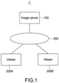
- Fig. 1 is a view showing a configuration of an information processing system according to an embodiment of the present technology.
- This information processing system 1 includes an image server 100 and one or more viewers 200A and 200B. Those can be connected to one another over a network 300.
- the network 300 may be a WAN (Wide Area Network) such as the Internet or may be a LAN (Local Area Network). Further, the network 300 may be wired or wireless.
- WAN Wide Area Network
- LAN Local Area Network
- the network 300 may be wired or wireless.
- the number of viewers may be three or more.
- viewers 200 when the viewers are not individually specified, those will be referred to as "viewers 200."
- the image server 100 and the one or more viewers 200 may be configured by, for example, a typical computer.
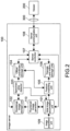
- Fig. 2 is a view showing the functional configurations of the image server 100 realized using a typical computer system.
- the image server 100 includes an image acquisition unit 109 (acquisition unit), a slide image accumulation unit 101, a thumbnail image generator 110 (generator), a thumbnail image storage unit 102, a specimen area detector 103 (detector), an offset coordinate storage unit 104 (first storage unit), a feature matching unit 105, a triangle and matrix storage unit 106, a server controller 107, and a server communication unit 108.
- Each functional unit is realized in a computer resource based on programs loaded into a RAM (Random Access Memory).
- the image acquisition unit 109 acquires an image over a network or data of a slide image recorded in a removable recording medium.
- the image acquisition unit 109 accumulates this data of the slide image and a slide ID in the slide image accumulation unit 101 with this data of the slide image being associated with the slide ID.
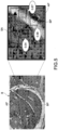
- the term of "slide image” means, as shown in Fig. 3 , an image obtained by capturing a glass slide 610 on which a plurality of sections 601 to 607 obtained by cutting a single specimen 600 in the same direction are placed, the plurality of sections 601 to 607 being arranged discretely and in one row.
- a plurality of glass slides on which a plurality of sections are placed are fabricated.
- the term of "slide ID" means an ID for individually identifying data of a plurality of slide images. Note that the phrase of "arranged in one row " means an arrangement state in a direction from one end to the other end of a glass slide, not limited to the precisely linearly arrangement state.
- the thumbnail image generator 110 generates thumbnail images of the slide images accumulated in the slide image accumulation unit 101.
- the thumbnail image generator 110 records data of the thumbnail images and the above-mentioned slide ID in the thumbnail image storage unit 102 with the data of the thumbnail images being associated with the above-mentioned slide ID.
- the term of "thumbnail image” means reduced data obtained by reducing a resolution of data of a slide image.
- the slide image accumulation unit 101 and the thumbnail image storage unit 102 are set in a rewritable non-volatile memory.
- the specimen area detector 103 reads out the data of the thumbnail image from the thumbnail image storage unit 102.
- the specimen area detector 103 detects, from the read-out data of the thumbnail image, a plurality of areas including the plurality of sections placed on the glass slide (hereinafter, referred to as specimen areas).
- the detection of the specimen areas is performed as follows, for example. That is, the specimen area detector 103 recognizes a point in an image at which the luminance sharply changes, as a boundary of an object on the glass slide (edge extraction).
- the specimen area detector 103 recognizes a closed curve having a size larger than a threshold, as an edge (contour) of the section. Subsequently, the specimen area detector 103 extracts specimen areas including the recognized section from the data of the thumbnail image.
- the specimen area detector 103 selects a range of the specimen area such that the section is positioned at almost the center of the specimen area and the section is within a range of the specimen area.
- the specimen areas have the same arbitrary shape and size. In this embodiment, each of the specimen areas is rectangular.
- the specimen area detector 103 calculates offset coordinates (position information) of each specimen area.
- offset coordinates means information indicating a position of each of individual specimen areas in a coordinate space of the slide image including images of a plurality of sections.
- offset coordinates means a value expressing, by a difference (distance) from an origin in two axial directions, a position of an arbitrary point in each specimen area (e.g., one vertex of rectangular specimen area, for example, lower left end) while, for example, one vertex of the rectangular glass slide (e.g., lower left end) is the origin.
- the specimen area detector 103 associates metadata of the calculated offset coordinates, the specimen area number of the specimen area indicated by those offset coordinates, and the slide number of the slide image including that specimen area with one another, and records the metadata in the offset coordinate storage unit 104.
- This "number” reflects a section cutting order, that is, an arrangement order of the sections in a direction almost orthogonally to a cutting surface.
- the "number” is expressed by an integer equal to or larger than one and set by the specimen area detector 103.
- the offset coordinate storage unit 104 is set in a rewritable non-volatile memory.
- the specimen area detector 103 performs feature matching between images of a plurality of specimen areas detected from data of a thumbnail image.
- the feature matching only needs to be performed by the same manner as the feature matching by a feature matching unit 150 to be described later.
- the specimen area detector 103 determines degrees of similarity among sections A to F within the plurality of specimen areas included in one slide image.
- the specimen area detector 103 performs grouping such that the specimen areas including the sections B and C having high degree of similarity are located close to each other and the specimen areas including the sections D and E having high degree of similarity are located close to each other.
- the specimen area detector 103 determines that the sections are continuous from the large section A on one side of the specimen 600 (e.g., root) to the small section F (e.g., tip). As shown in Fig. 12 , the specimen area detector 103 sets continuous specimen area numbers such that position intervals of feature points decrease.
- the specimen area detector 103 determines degrees of similarity between specimen areas at both ends of a certain slide image and specimen areas at both ends of a different slide image.
- the specimen area detector 103 determines the slide images including the specimen areas having a high degree of similarity as continuous slide images, and sets continuous slide numbers.
- the specimen area detector 103 rewrites the slide IDs recorded in the slide image accumulation unit 101 and the thumbnail image storage unit 102, using the set slide numbers.
- the specimen area number and the slide number may be modified by the user through the viewer 200.
- the specimen area number and the slide number may be set by the user through the viewer 200.
- information inputted into an LIS may be loaded into the viewer 200 to set the specimen area number and the slide number.
- the feature matching unit 105 performs the feature matching between images of the specimen areas of each of the slide images accumulated in the slide image accumulation unit 101 (to be described later in detail). Specifically, the feature matching unit 105 reads out data of the slide image from the slide image accumulation unit 101. Further, the feature matching unit 105 reads out, from the offset coordinate storage unit 104, the plurality of specimen area numbers and offset coordinates associated with the slide number associated with data of the read-out slide image. The feature matching unit 105 detects the plurality of specimen areas from the slide image, based on the read-out offset coordinates and a size common to each specimen area. The feature matching unit 105 performs the feature matching between images of the plurality of detected specimen areas, and calculates a triangle and an affine transformation matrix.
- the feature matching unit 105 records, in the triangle and matrix storage unit 106, metadata of data of the calculated triangle and affine transformation matrix, the specimen area number that identifies each specimen area, and the slide number with the metadata being associated with each other.
- the triangle and matrix storage unit 106 is set in a rewritable non-volatile memory.
- the server controller 107 In response to a request from the viewer 200, the server controller 107 reads out corresponding image data from the slide image accumulation unit 101, and provides the image data to the viewer 200 through the server communication unit 108.
- the feature matching unit 105 divides the image of the detection area A into a plurality of triangles having the employed feature points (black points in the figure) as vertices. As shown in Fig. 7 , while maintaining the division topology of the detection area A, the feature matching unit 105 also divides the image of the detection area B into a plurality of triangles having the corresponding points (white points in the figure) corresponding to the employed feature points (black points in the figure) as vertices.
- the alignment data generation unit 208 calculates an offset amount in the two axial directions between the plurality of specimen areas in the coordinate space of the slide image. More specifically, the alignment data generation unit 208 calculates, as alignment data, an offset amount of coordinates in the two axial directions in the coordinate space of the specimen area between a triangle including a point located at center coordinates of a certain specimen area as a reference point and a triangle including a point corresponding to the reference point in a different specimen area, for example.
- the alignment data generation unit 208 records the calculated alignment data in the alignment data storage unit 209.
- the alignment data storage unit 209 is set in a rewritable non-volatile memory.
- a rectangular area at a lower left corner of the first specimen area 621 is displayed on the display unit 201 as a display area 641.
- the user uses the input unit 202 such as a mouse to input an order for moving an image of the display area 641 up, down, left, and right.
- the display area horizontally moves within the first specimen area 621 up to a display area 641a at a lower right corner of the first specimen area 621 (arrow A).
- the display area moves a display area 641b at a lower left corner of the second specimen area 622 (arrow B). It is assumed that such movements between the specimen areas are repeated, the display area moves to a display area 641c at a lower right corner of a seventh specimen area 621, and further an instruction of moving in the right-hand direction is inputted. In this case, no specimen areas are present on the right-hand side of a seventh specimen area 627 on the first glass slide 610. Therefore, the display area moves to a display area 641d at a lower left corner of an eighth specimen area 628 on the second glass slide 620 (arrow C).
- the user selects the discrete display as a display mode.
- the viewer controller 207 uses the viewer communication unit 204 to read out the thumbnail image of the slide image associated with the slide number and recorded in the thumbnail image storage unit 102 of the image server 100.
- the viewer controller 207 causes the display processor 205 to generate a specimen area selection screen based on the read-out slide number and thumbnail image of the slide image.
- the viewer controller 207 causes the display unit 201 to display the specimen area selection screen.
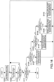
- Fig. 15 is a view showing the specimen area selection screen.
- a specimen area selection screen 220 includes a slide tray 221, a specimen area tray 222, an observation display section 223, and a display-area display section 224.
- thumbnail images 230, 231, and 232 of a slide image read out by the viewer controller 207 from the image server 100 are displayed as a list.
- the thumbnail images 230, 231, and 232 of the slide image are arranged in a slide number order from the upper side to the lower side.
- the input unit 202 such as a mouse, the user selects the one thumbnail image 231 from the plurality of thumbnail images 230, 231, and 232 displayed in the slide tray 221.
- the viewer controller 207 causes the display processor 205 to display the selected thumbnail image 231 in an identifiable form with a frame line (231A) or the like and to display a thumbnail image 231C corresponding to the selected thumbnail image 231 in the display-area display section 224.
- the viewer controller 207 use the viewer communication unit 204 to read out the specimen area number and the offset coordinates being the metadata associated with the slide number associated with the selected thumbnail image and recorded in the offset coordinate storage unit 104 of the image server 100. Further, the viewer controller 207 uses the viewer communication unit 204 to read out the specimen area number and the triangle and affine transformation matrix being the metadata associated with the slide number and recorded in the triangle and matrix storage unit 106 of the image server 100. Based on the read-out offset coordinates and slide number being the metadata, the viewer controller 207 causes the display processor 205 to display thumbnail images 231a to 231g of the plurality of specimen areas within the selected thumbnail image 231, in the specimen area tray 222 as a list. The thumbnail images 231a to 231g of the specimen areas are arranged in a specimen area number order from the left to the right.
- the user selects one thumbnail image 231d among the plurality of thumbnail images 231a to 231g displayed in the specimen area tray 222.
- the selected thumbnail image 231d is displayed to be identifiable with a frame line (231B) or the like.
- the image of the specimen area of the selected thumbnail image 231d is displayed in the observation display section 223.
- part of the specimen area is displayed at an arbitrary resolution.
- a position of the specimen area currently displayed in the observation display section 223 is displayed to be identifiable with a frame line (224a) or the like. Note that the selection operations for a slide being a display target and the specimen area are common in the discrete display, the jump display, and the synchronous display.
- the viewer controller 207 detects an input by the user into the input unit 202 and determines the slide number and the specimen area number of the slide and the specimen area to be first displayed. Then, the viewer controller 207 provides the offset coordinates associated with the slide number and the specimen area number being the metadata to the first coordinate calculation unit 203 that performs processing for the discrete display.
- the first coordinate calculation unit 203 calculates the position information of the display area to be first displayed, based on the offset coordinates of the specimen area that is the metadata and on a size and an initial position (e.g., lower left corner of specimen area) that are common to the display areas. The size and the initial position common to the display areas are recorded in a rewritable non-volatile memory.
- the first coordinate calculation unit 203 provides the calculated position information to the viewer controller 207.
- the viewer controller 207 transmits a request for acquiring an image corresponding to the display area to the image server 100 through the viewer communication unit 204.
- the server controller 107 of the image server 100 receives this request through the server communication unit 108, and reads out the image data of the display area included in the request from the slide image accumulation unit 101.
- the server controller 107 transmits the read-out image data to the viewer 200 through the server communication unit 108.
- the user inputs an order for moving the image of the display area displayed in the observation display section 223 up, down, left, and right.
- the viewer controller 207 detects an input of a moving order into the input unit 202 by the user.
- the viewer controller 207 provides the detected moving order to the first coordinate calculation unit 203.
- the first coordinate calculation unit 203 calculates the position information of the display area at a moving destination.
- the first coordinate calculation unit 203 provides the calculated position information to the viewer controller 207.
- the viewer controller 207 transmits a request for acquiring an image corresponding to the display area to the image server 100 through the viewer communication unit 204.
- Step S101 in response to the request from the viewer 200, the server controller 107 of the image server 100 reads out the image data corresponding to the slide image accumulation unit 101, and transmits the image data to the viewer 200 through the server communication unit 108. With this, the viewer 200 acquires the image data of the display area at the moving destination, and updates the display contents of the display unit 201 (Step S102).
- the first coordinate calculation unit 203 determines, based on the calculated position information, that the display area at the moving destination has reached the boundary of the specimen area (Yes in Step 103), the first coordinate calculation unit 203 determines which end (right end, lower end, left end, and upper end) of the specimen area that boundary is located at (Steps S104, S105, and S106). If the display area is located at the right end of the specimen area, the first coordinate calculation unit 203 increments the specimen area number of the specimen area being a display target when an instruction of moving in the right-hand direction from the user is detected (Yes in Step 104). With this, the obtained specimen area number becomes a specimen area number of a specimen area to be next displayed.
- the first coordinate calculation unit 203 sets the display area within the specimen area corresponding to the specimen area number obtained by the increment in the following manner. That is, the first coordinate calculation unit 203 maintains a Y-offset between the upper end of the specimen area and the upper end of the display area, and sets the display area within the specimen area at the moving destination such that the left end of the specimen area and the left end of the display area correspond to each other (Step S107).
- the first coordinate calculation unit 203 increments the specimen area number of the specimen area being the display target.
- the first coordinate calculation unit 203 sets the display area within the specimen area corresponding to the specimen area number obtained by the increment in the following manner. That is, the first coordinate calculation unit 203 maintains an X-offset between the left end of the specimen area and the left end of the display area, and sets the display area within the specimen area at the moving destination such that the upper end of the specimen area and the upper end of the display area correspond to each other (Step S108).
- the first coordinate calculation unit 203 decrements the specimen area number of the specimen area being the display target.
- the first coordinate calculation unit 203 sets the display area within the specimen area corresponding to the specimen area number obtained by the decrement in the following manner. That is, the first coordinate calculation unit 203 maintains the X-offset between the left end of the specimen area and the left end of the display area, and sets the display area within the specimen area at the moving destination such that the lower end of the specimen area and the lower end of the display area correspond to each other (Step S110).
- the first coordinate calculation unit 203 determines that a specimen area to be next displayed is not present (Yes in Step 111), the first coordinate calculation unit 203 terminates the discrete display processing.
- the information processing system 1 includes the image acquisition unit 109 that acquires image data obtained by capturing a slide on which a plurality of sections obtained by cutting a single specimen in the same direction are discretely placed, the specimen area detector 103 that detects the plurality of specimen areas in the acquired image data, and calculates position information relatively indicating positions of the individual specimen areas in a coordinate space of the image data, the plurality of specimen areas having the same shape and including the individual sections, the offset coordinate storage unit 104 that stores the calculated position information, and the viewer controller 207 that switches display between the specimen areas based on the stored position information.
- the viewer controller 207 switches display between the specimen areas based on the position information being the metadata.
- the viewer controller 207 can jump the areas other than the specimen areas and switch display between the specimen areas irrespective of the fact that the image data acquired by the acquisition unit is the image data obtained by capturing the slide itself on which the plurality of sections are placed.
- the first storage unit can switch display between the specimen areas efficiently and at high speed.
- the display processing can be efficiently performed as in the case where a plurality of specimen areas detected from single image data are displayed in order.
- the information processing system 1 further includes the thumbnail image thumbnail image generator 110 110 that generates reduced data by reducing a resolution of the image data.
- the specimen area detector 103 detects the plurality of specimen areas in the image data by detecting the plurality of specimen areas from the reduced data.
- a plurality of image data items of the plurality of specimen areas are managed in the cutting order.
- the viewer controller 207 receives, from the user, specification of a specimen area to be displayed in the acquired image data and a range therein, the viewer controller 207 calculates the range in the specified specimen area as the display area. If the display area is located at an end of the specimen area, when the viewer controller 207 receives, from the user, an instruction of moving the display area outside the end, the viewer controller 207 switches to display a neighbor specimen area in the cutting order based on the stored position information.
- the viewer controller 207 when the viewer controller 207 receives, from the user, an instruction of moving the display area outside the end in the one axial direction, the viewer controller 207 performs switching to the display of a neighbor specimen area in the cutting order while fixing a position in the other axial direction.
- a position of the display area in the specimen area at the moving destination corresponds to a position of the display area in the specimen area at a moving source at the moving destination. Therefore, a convenience for the user can be provided.
- the image acquisition unit 109 acquires image data obtained by capturing a slide on which a plurality of sections obtained by cutting a single specimen in the same direction are placed discretely and in one row.
- the viewer controller 207 calculates, when the calculated display area is located at an end of the specimen area in an arrangement direction of the plurality of specimen areas in a coordinate space of the image data and the viewer controller 207 receives, from the user, an instruction of moving the display area in the arrangement direction beyond the end, the display area of the specimen area at the moving destination based on the stored position information.
- the image acquisition unit 109 acquires image data obtained by capturing a slide on which the plurality of sections obtained by cutting a single specimen in the same direction are discretely placed.
- the specimen area detector 103 detects the plurality of specimen areas in the acquired image data, and calculates position information relatively indicating positions of the individual specimen areas in a coordinate space of the image data, the plurality of specimen areas having the same shape and including the individual sections.
- the offset coordinate storage unit 104 stores the calculated position information.
- the viewer controller 207 switches display between the specimen areas based on the stored position information.
- the jump display will be described.
- processing for displaying corresponding areas of the specimen area in order is performed.
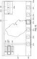
- Fig. 16 is a view showing a specific example of the jump display.
- the figure shows an example in which, as in Fig. 13 , the first to fourteenth sections 601 to 614 are placed on the first and second glass slides 610 and 620 in this order and the first to fourteenth specimen areas 621 to 634 respectively including the first to fourteenth sections 601 to 614 are detected.
- the thumbnail image of the specimen area 622 on the right next to the thumbnail image of the currently displayed first specimen area 621 is selected from the specimen area tray 222 ( Fig. 15 ) of the specimen area selection screen 220, as the specimen area at the moving destination.
- the display area moves to a display area 642a of the second specimen area 622 (arrow D).
- the display areas 642 and 642a are located at the same position in the coordinate space of the specimen areas 621 and 622 having the same shape. That is, sites continuous in the direction almost orthogonal to the cutting surface of the specimen are displayed as the display areas 642 and 642a. It is assumed that movements between the specimen areas are repeated and the display area moves to the display area 642b of the seventh specimen area 621 (located at the same position as the display areas 642 and 642a in the coordinate space of the specimen areas having the same shape).
- Fig. 17 is a flowchart showing the jump display processing by the viewer 200.
- a slide and a specimen area to be first displayed are selected. Further, the user selects the jump display as the display mode, for example, using the input unit 202.
- the user uses the input unit 202 such as a mouse to input an order for moving the image of the display area displayed in the observation display section 223 up, down, left, and right.
- the viewer controller 207 detects an input of a moving order into the input unit 202 by the user, and provides the detected moving order to the second coordinate calculation unit 206. Based on the moving order, the second coordinate calculation unit 206 calculates the position information of the display area at the moving destination. The second coordinate calculation unit 206 provides the calculated position information to the viewer controller 207.
- the viewer controller 207 transmits a request for acquiring an image corresponding to that display area to the image server 100 through the viewer communication unit 204.
- the user inputs an order for moving the display to an image of a different specimen area from the image of the specimen area displayed in the observation display section 223. That input is performed by, for example, selecting a specimen area on the right or left next to the currently displayed specimen area among a group of thumbnail images displayed in the specimen area tray 222 ( Fig. 15 ) of the specimen area selection screen 220. Alternatively, that input is performed by selecting a slide above or below the currently displayed slide among a group of thumbnail images displayed in the slide tray 221 ( Fig. 15 ) of the specimen area selection screen 220.
- the viewer controller 207 determines whether the inputted specimen area at the moving destination is positioned on the right or left next to the currently displayed specimen area, or whether the slide at the moving destination is positioned above or below the currently displayed specimen area (Steps S205 and S206).
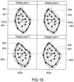
- Fig. 18 is a view showing a specific example of the synchronous display.
- a plurality of (e.g., four) specimen areas 621 to 624 are selected by the user as display targets.
- the plurality of specimen areas 621 to 624 are individually assigned and displayed in display spaces 651 to 654 obtained by dividing the observation display section 223 of the specimen area selection screen 220 ( Fig. 15 ) into a plurality of areas having almost the same size. More specifically, the plurality of specimen areas 621 to 624 are displayed such that positions of points 621a to 624a respectively located at centers of the plurality of specimen areas 621 to 624 correspond to each other in the display spaces 651 to 654 (located at center).
- the viewer controller 207 divides the observation display section 223 of the specimen area selection screen 220 ( Fig. 15 ) serving as the display space into display spaces as many as the plurality of (e.g., four) specimen areas specified. Then, the viewer controller 207 provides coordinate information of each of the divided display spaces to the third coordinate calculation unit 210.
- the third coordinate calculation unit 210 sets the display area such that the center points of the plurality of specimen areas correspond to each other. That is, based on the offset coordinates being the metadata and the alignment data, the third coordinate calculation unit 210 sets the display area such that the positions of points located at the centers of the plurality of specimen areas correspond to each other in the display spaces (located at center).
- the third coordinate calculation unit 210 calculates position information of each of the set display areas.
- the third coordinate calculation unit 210 provides the obtained position information to the viewer controller 207.
- the viewer controller 207 transmits a request for acquiring an image corresponding to that display area to the image server 100 through the viewer communication unit 204.
- the display processor 205 individually assigns and displays the image data of the plurality of display areas in the display spaces obtained by dividing the observation display section 223 of the specimen area selection screen 220 ( Fig. 15 ) displayed on the display unit 201 into the plurality of areas having almost the same size.
- the viewer controller 207 when the viewer controller 207 receives, from the user, specification of the plurality of specimen areas to be displayed in the acquired image data, the viewer controller 207 divides the display space into display spaces as many as the plurality of specimen areas specified. Then, based on the stored position information and the stored offset amount, the viewer controller 207 calculates a display area to be displayed in the plurality of display spaces such that positions of feature points to be displayed in the plurality of display spaces correspond to each other in the specimen areas.
- the viewer controller 207 can cause the positions of the feature points in the specimen areas to be displayed in the plurality of display spaces to correspond to each other. Further, by using the metadata for setting the display area, it is possible to accurately calculate the corresponding display area and perform the display processing efficiently and at high speed.
- Fig. 19 is a view showing a hardware configuration of a typical computer 400.
- the computer 400 includes a CPU (Central Processing Unit) 401, a ROM (Read Only Memory) 402, and a RAM 403. Further, the computer 400 includes an input apparatus 404, an output apparatus 405, a storage apparatus 406, a medium interface apparatus 407, a network connection apparatus 408, and a bus 409 that connect them.
- a CPU Central Processing Unit
- ROM Read Only Memory
- RAM Random Access Memory
- the computer 400 includes an input apparatus 404, an output apparatus 405, a storage apparatus 406, a medium interface apparatus 407, a network connection apparatus 408, and a bus 409 that connect them.
- the CPU 401 functions as an arithmetic processing apparatus and a control apparatus and controls general operations of the computer 400 according to various programs.
- the ROM 402 stores programs, arithmetic parameters, and the like to be used by the CPU 401.
- the RAM 403 temporarily stores programs to be executed by the CPU 401, parameters appropriately changing in execution thereof, and the like.
- a synchronous processor 25 of a synchronous server 40, viewer controllers 37A and 37B of viewers 30A and 30B, and the like are realized by the CPU 401, the programs stored in the ROM 402, a working area of the RAM 403, and the like in the hardware configuration of the computer 400, for example.
- the input apparatus 404 is constituted of an input means for the user to input information, such as a mouse, a keyboard, a touch panel, a button, a microphone, a switch, and a lever, an input control circuit that generates an input signal based on an input by the user and outputs the input signal to the CPU 401, and the like.
- an input means for the user to input information such as a mouse, a keyboard, a touch panel, a button, a microphone, a switch, and a lever
- an input control circuit that generates an input signal based on an input by the user and outputs the input signal to the CPU 401, and the like.
- the output apparatus 405 includes a display apparatus, for example, a CRT (Cathode Ray Tube) display apparatus, a crystal-liquid display (LCD) apparatus, or an OLED (Organic Light Emitting Diode) apparatus.
- the output apparatus 405 further includes an audio output apparatus such as a speaker and headphones.
- the storage apparatus 406 is an apparatus for storing programs and user data.
- the storage apparatus 406 is constituted of a recording medium, a reading/writing apparatus that reads/writes data from/on the recording medium, and the like.
- the storage apparatus 106 is constituted of, for example, an HDD (Hard Disk Drive), an SSD (Solid State Drive), and the like.
- the medium interface apparatus 407 is a reader/writer for the recording medium.
- the medium interface apparatus 407 reads/writes data from/on a removable recording medium 2A such as a magnetic disc, an optical disc, a magnetooptical disc, and a semiconductor memory installed therein.
- the network connection apparatus 408 is an interface for connecting to the network 300, for example.
- the network connection apparatus 408 may be an apparatus adapted for a wireless LAN (Local Area Network), a wireless USB-adapted apparatus, or a wired communication apparatus that performs a communication via a wire.
- a wireless LAN Local Area Network
- a wireless USB-adapted apparatus or a wired communication apparatus that performs a communication via a wire.
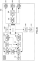
- Fig. 20 is a view showing a configuration of an information processing apparatus according to a modified example.
- the information processing system 1 including the image server 100 and the one or more viewers 200A and 200B that can be connected to one another over the network 300 has been described. Otherwise, a single information processing apparatus 500 may be adopted as the information processing system.
- the information processing apparatus 500 has the same configurations as the functional configurations of the image server 100 and the viewer 200 according to the above embodiment.
- the information processing apparatus 500 is different from the above embodiment in that the information processing apparatus 500 does not include the server controller 107, the server communication unit 108, and the viewer communication unit 204.
- a controller 207A has the same function as the viewer controller 207 according to the above embodiment.
- the controller 207A reads out data directly from the slide image accumulation unit 101, the thumbnail image storage unit, the offset coordinate storage unit 104, and the triangle and matrix storage unit 106.
- the information processing apparatus 500 may be constituted of, for example, the above-mentioned typical computer 400. Also, this information processing apparatus 500 can perform similar processing as the above embodiment.
Landscapes
- Engineering & Computer Science (AREA)
- Physics & Mathematics (AREA)
- General Physics & Mathematics (AREA)
- Theoretical Computer Science (AREA)
- Multimedia (AREA)
- Computer Vision & Pattern Recognition (AREA)
- General Engineering & Computer Science (AREA)
- Optics & Photonics (AREA)
- Chemical & Material Sciences (AREA)
- Analytical Chemistry (AREA)
- General Health & Medical Sciences (AREA)
- Health & Medical Sciences (AREA)
- Life Sciences & Earth Sciences (AREA)
- Biomedical Technology (AREA)
- Molecular Biology (AREA)
- Human Computer Interaction (AREA)
- Controls And Circuits For Display Device (AREA)
- Microscoopes, Condenser (AREA)
- Investigating Or Analysing Materials By Optical Means (AREA)
- Length Measuring Devices By Optical Means (AREA)
- Processing Or Creating Images (AREA)
- Image Analysis (AREA)
Applications Claiming Priority (2)
| Application Number | Priority Date | Filing Date | Title |
|---|---|---|---|
| JP2011184895A JP6035716B2 (ja) | 2011-08-26 | 2011-08-26 | 情報処理システム及び情報処理方法 |
| PCT/JP2012/004510 WO2013031077A1 (ja) | 2011-08-26 | 2012-07-12 | 情報処理システム及び情報処理方法 |
Publications (4)
| Publication Number | Publication Date |
|---|---|
| EP2749927A1 EP2749927A1 (en) | 2014-07-02 |
| EP2749927A4 EP2749927A4 (en) | 2015-04-29 |
| EP2749927B1 EP2749927B1 (en) | 2017-04-05 |
| EP2749927B2 true EP2749927B2 (en) | 2025-06-25 |
Family
ID=47755611
Family Applications (1)
| Application Number | Title | Priority Date | Filing Date |
|---|---|---|---|
| EP12826830.7A Active EP2749927B2 (en) | 2011-08-26 | 2012-07-12 | Information processing system and information processing method |
Country Status (7)
| Country | Link |
|---|---|
| US (1) | US9008388B2 (enExample) |
| EP (1) | EP2749927B2 (enExample) |
| JP (1) | JP6035716B2 (enExample) |
| CN (1) | CN103180770A (enExample) |
| BR (1) | BR112013009021A2 (enExample) |
| CA (1) | CA2813379A1 (enExample) |
| WO (1) | WO2013031077A1 (enExample) |
Families Citing this family (21)
| Publication number | Priority date | Publication date | Assignee | Title |
|---|---|---|---|---|
| EP3415162A1 (en) | 2011-02-11 | 2018-12-19 | Merck Patent GmbH | Anti-alpha-v integrin antibody for the treatment of prostate cancer |
| JP6455829B2 (ja) * | 2013-04-01 | 2019-01-23 | キヤノン株式会社 | 画像処理装置、画像処理方法、およびプログラム |
| CN105144269A (zh) * | 2013-04-22 | 2015-12-09 | 三菱电机株式会社 | 动态标签配置装置、显示装置、动态标签配置方法和显示方法 |
| USD740842S1 (en) * | 2013-08-20 | 2015-10-13 | Jovia, Inc. | Display screen or a portion thereof with graphical user interface |
| US11790154B2 (en) | 2013-10-09 | 2023-10-17 | Interactive Solutions Corp. | Mobile terminal device, slide information managing system, and a control method of mobile terminal |
| JP6465372B2 (ja) * | 2013-10-09 | 2019-02-06 | 株式会社インタラクティブソリューションズ | 携帯端末装置、スライド情報管理システム及び携帯端末の制御方法 |
| JP2015082095A (ja) * | 2013-10-24 | 2015-04-27 | 株式会社キーエンス | 画像処理装置、顕微鏡システム、画像処理方法およびプログラム |
| US9823755B2 (en) * | 2015-02-26 | 2017-11-21 | Konica Minolta Laboratory U.S.A., Inc. | Method and apparatus for interactive user interface with wearable device |
| EP3345161B1 (en) * | 2015-09-02 | 2023-01-25 | Ventana Medical Systems, Inc. | Image processing systems and methods for displaying multiple images of a biological specimen |
| KR101863227B1 (ko) * | 2016-07-12 | 2018-05-31 | 주식회사 인피니트헬스케어 | 디지털 병리 시스템의 환자 케이스 동일성 판단 방법 |
| JP1596805S (enExample) * | 2017-04-27 | 2018-02-05 | ||
| JP7006111B2 (ja) * | 2017-10-06 | 2022-01-24 | 株式会社ニコン | 位置を決定する装置、方法、およびプログラム、画像を表示する装置、方法、およびプログラム |
| CN111433594B (zh) * | 2017-10-16 | 2023-07-11 | 株式会社日立高新技术 | 拍摄装置 |
| WO2020124084A1 (en) * | 2018-12-15 | 2020-06-18 | The Brigham And Women's Hospital, Inc. | Augmented digital microscopy for lesion analysis |
| CN110556172A (zh) * | 2019-09-18 | 2019-12-10 | 杭州智团信息技术有限公司 | 玻片归档方法、设备终端、玻片归档系统和可读存储介质 |
| US12323864B2 (en) | 2019-10-21 | 2025-06-03 | Beijing Xiaomi Mobile Software Co., Ltd. | Cell reselection method and apparatus, and communication device |
| JP7020523B2 (ja) * | 2020-10-08 | 2022-02-16 | 株式会社リコー | 画像表示システム、画像表示方法、及びプログラム |
| JP7660421B2 (ja) * | 2021-04-12 | 2025-04-11 | キヤノンメディカルシステムズ株式会社 | 情報処理装置、情報処理方法、およびプログラム |
| CN114066875A (zh) * | 2021-11-25 | 2022-02-18 | 数坤(北京)网络科技股份有限公司 | 切片图像处理方法、装置、存储介质及终端设备 |
| CN114332060A (zh) * | 2021-12-29 | 2022-04-12 | 深圳乐易通医疗设备研发有限公司 | 一种病理样本的制片检测系统 |
| WO2025189130A1 (en) * | 2024-03-08 | 2025-09-12 | PAIGE.AI, Inc. | Identifying and analyzing multiple levels of core tissue |
Citations (2)
| Publication number | Priority date | Publication date | Assignee | Title |
|---|---|---|---|---|
| US20020135678A1 (en) † | 1996-08-23 | 2002-09-26 | Bacus Research Laboratories, Inc. | Method and apparatus for internet, intranet, and local viewing of virtual microscope slides |
| US20090141126A1 (en) † | 2000-05-03 | 2009-06-04 | Aperio Technologies, Inc. | Fully Automatic Rapid Microscope Slide Scanner |
Family Cites Families (29)
| Publication number | Priority date | Publication date | Assignee | Title |
|---|---|---|---|---|
| JPS6051814A (ja) * | 1983-08-31 | 1985-03-23 | Akihiro Fujimura | 脳の神経繊維の配線構造を記録解析しうる顕微鏡検査装置 |
| US4836667A (en) * | 1986-05-06 | 1989-06-06 | Slidex Corporation | Microscope |
| JPS62269924A (ja) * | 1986-05-06 | 1987-11-24 | Suraidetsukusu Kk | 顕微鏡 |
| JPH06258578A (ja) * | 1993-03-04 | 1994-09-16 | Kanagawa Kagaku Gijutsu Akad | 試料断面からの立体情報画像化装置及びその試料断面画像の観察方法 |
| US6272235B1 (en) | 1997-03-03 | 2001-08-07 | Bacus Research Laboratories, Inc. | Method and apparatus for creating a virtual microscope slide |
| US6404906B2 (en) | 1997-03-03 | 2002-06-11 | Bacus Research Laboratories,Inc. | Method and apparatus for acquiring and reconstructing magnified specimen images from a computer-controlled microscope |
| US6031930A (en) * | 1996-08-23 | 2000-02-29 | Bacus Research Laboratories, Inc. | Method and apparatus for testing a progression of neoplasia including cancer chemoprevention testing |
| US6118888A (en) * | 1997-02-28 | 2000-09-12 | Kabushiki Kaisha Toshiba | Multi-modal interface apparatus and method |
| GB2341231A (en) * | 1998-09-05 | 2000-03-08 | Sharp Kk | Face detection in an image |
| US6466690C1 (en) * | 2000-12-19 | 2008-11-18 | Bacus Res Lab Inc | Method and apparatus for processing an image of a tissue sample microarray |
| US7155049B2 (en) * | 2001-01-11 | 2006-12-26 | Trestle Acquisition Corp. | System for creating microscopic digital montage images |
| JP2002229537A (ja) * | 2001-01-30 | 2002-08-16 | Hitachi Medical Corp | 画像表示装置及びフィルム出力画像選択装置 |
| JP4156851B2 (ja) * | 2002-03-22 | 2008-09-24 | オリンパス株式会社 | マイクロダイセクション装置 |
| US20040021911A1 (en) * | 2002-07-31 | 2004-02-05 | Corson John F. | Array scanner noise reduction system |
| US7925070B2 (en) * | 2004-03-30 | 2011-04-12 | Sysmex Corporation | Method for displaying virtual slide and terminal device for displaying virtual slide |
| JP4542386B2 (ja) * | 2004-07-30 | 2010-09-15 | シスメックス株式会社 | 画像表示システム、画像提供装置、画像表示装置、およびコンピュータプログラム |
| CN1775171B (zh) * | 2004-08-30 | 2011-12-14 | 株式会社东芝 | 医用图像显示装置 |
| KR101274088B1 (ko) * | 2005-06-13 | 2013-06-12 | 트리패스 이미징, 인코포레이티드 | 현미경 이미지 장치를 이용한 슬라이드상의 시료 내의 물체를 재배치하기 위한 시스템 및 방법 |
| JP4926416B2 (ja) * | 2005-06-15 | 2012-05-09 | キヤノン株式会社 | 画像表示方法、プログラム、記録媒体及び画像表示装置 |
| JP2007024927A (ja) * | 2005-07-12 | 2007-02-01 | Olympus Corp | 顕微鏡画像撮影装置 |
| JP4973162B2 (ja) * | 2006-12-01 | 2012-07-11 | 株式会社ニコン | 画像処理装置、画像処理プログラム及び観察システム |
| JP4283303B2 (ja) * | 2006-12-12 | 2009-06-24 | ザイオソフト株式会社 | 画像表示制御装置、画像表示制御プログラム及び画像表示制御方法 |
| US8671344B2 (en) * | 2009-02-02 | 2014-03-11 | Panasonic Corporation | Information display device |
| US20100214321A1 (en) * | 2009-02-24 | 2010-08-26 | Nokia Corporation | Image object detection browser |
| JP5152077B2 (ja) * | 2009-04-01 | 2013-02-27 | ソニー株式会社 | 生体像提示装置、生体像提示方法及びプログラム並びに生体像提示システム |
| CN102665769A (zh) * | 2009-11-13 | 2012-09-12 | 默克专利有限公司 | 与装载化疗剂的纳米颗粒连接的抗整联蛋白抗体 |
| US8564623B2 (en) * | 2009-12-11 | 2013-10-22 | Molecular Devices, Llc | Integrated data visualization for multi-dimensional microscopy |
| JP5434621B2 (ja) * | 2010-01-19 | 2014-03-05 | ソニー株式会社 | 情報処理装置、情報処理方法、及びそのプログラム |
| WO2012155267A1 (en) | 2011-05-13 | 2012-11-22 | Fibics Incorporated | Microscopy imaging method and system |
-
2011
- 2011-08-26 JP JP2011184895A patent/JP6035716B2/ja active Active
-
2012
- 2012-07-12 BR BR112013009021A patent/BR112013009021A2/pt not_active IP Right Cessation
- 2012-07-12 CN CN201280003405XA patent/CN103180770A/zh active Pending
- 2012-07-12 WO PCT/JP2012/004510 patent/WO2013031077A1/ja not_active Ceased
- 2012-07-12 US US13/878,780 patent/US9008388B2/en active Active
- 2012-07-12 CA CA2813379A patent/CA2813379A1/en not_active Abandoned
- 2012-07-12 EP EP12826830.7A patent/EP2749927B2/en active Active
Patent Citations (2)
| Publication number | Priority date | Publication date | Assignee | Title |
|---|---|---|---|---|
| US20020135678A1 (en) † | 1996-08-23 | 2002-09-26 | Bacus Research Laboratories, Inc. | Method and apparatus for internet, intranet, and local viewing of virtual microscope slides |
| US20090141126A1 (en) † | 2000-05-03 | 2009-06-04 | Aperio Technologies, Inc. | Fully Automatic Rapid Microscope Slide Scanner |
Non-Patent Citations (6)
| Title |
|---|
| A. BHALERAO: "Multiresolution Image Segmentation", PD THESIS, November 1991 (1991-11-01), XP055448058 † |
| B. LAHRMANN ET AL.: "Robust Gridding of TMAs After Whole-Slide Imaging Using Tem- plate Matching", CYTOMETRY PART A, vol. 77A, 2010, pages 1169 - 1176, XP055448031 † |
| CARL ZEISS, AXIOVISION - PERFORM TO PERFECTION, February 2010 (2010-02-01), XP055448034 † |
| J. PETERWITZ: "Grundlagen: Bildverarbeitung/Objekterkennung", SEMINARARBEIT, FAKULTAT F0R INFORMATIK, 5 July 2006 (2006-07-05), pages 1 - 34, XP055347011 † |
| J. SI ET AL.: "Detecting regions of interest in images", SPIE NEWSROOM, May 2006 (2006-05-01), pages 1 - 3, XP055448048 † |
| J. WANG ET AL.: "Unsupervised Multiresolution Segmentation for Images with Low Depth of Field", IEEE TRANSACTIONS ON PATTERN ANALYSIS AND MACHINE INTELLIGENCE, vol. 23, no. 1, January 2001 (2001-01-01), pages 85 - 90, XP001008999 † |
Also Published As
| Publication number | Publication date |
|---|---|
| BR112013009021A2 (pt) | 2016-07-12 |
| JP6035716B2 (ja) | 2016-11-30 |
| EP2749927A1 (en) | 2014-07-02 |
| WO2013031077A1 (ja) | 2013-03-07 |
| CA2813379A1 (en) | 2013-03-07 |
| CN103180770A (zh) | 2013-06-26 |
| US9008388B2 (en) | 2015-04-14 |
| US20130194312A1 (en) | 2013-08-01 |
| EP2749927B1 (en) | 2017-04-05 |
| JP2013045069A (ja) | 2013-03-04 |
| EP2749927A4 (en) | 2015-04-29 |
Similar Documents
| Publication | Publication Date | Title |
|---|---|---|
| EP2749927B2 (en) | Information processing system and information processing method | |
| JP7115508B2 (ja) | 病理画像表示システム、病理画像表示方法及びプログラム | |
| US10067658B2 (en) | Image processing apparatus, method, and computer-readable medium for controlling the display of an image | |
| JP6091137B2 (ja) | 画像処理装置、画像処理システム、画像処理方法およびプログラム | |
| US8830313B2 (en) | Information processing apparatus, stage-undulation correcting method, program therefor | |
| JP4667944B2 (ja) | 画像作成装置 | |
| EP2464093B1 (en) | Image file generation device, image processing device, image file generation method, and image processing method | |
| US20190304409A1 (en) | Image processing apparatus and image processing method | |
| JP6448996B2 (ja) | 顕微鏡システム | |
| US10424046B2 (en) | Information processing apparatus, method and program therefore | |
| US20130063585A1 (en) | Information processing apparatus, information processing method, and program | |
| JP6447675B2 (ja) | 情報処理装置、情報処理方法、プログラム及び顕微鏡システム | |
| JP2013152426A (ja) | 画像処理装置、画像処理システム、画像処理方法、およびプログラム | |
| JP6702360B2 (ja) | 情報処理方法、情報処理システム及び情報処理装置 | |
| CN102314680A (zh) | 图像处理装置、图像处理系统、图像处理方法和程序 | |
| US20130265329A1 (en) | Image processing apparatus, image display system, method for processing image, and image processing program | |
| JP5906605B2 (ja) | 情報処理装置 | |
| JP2014048325A (ja) | 情報処理装置、情報処理方法、および情報処理プログラム | |
| JP4878815B2 (ja) | 顕微鏡装置 | |
| JP2017041273A (ja) | 情報処理システム及び情報処理方法 | |
| JP6338730B2 (ja) | 表示データを生成する装置、方法、及びプログラム | |
| US11972619B2 (en) | Information processing device, information processing system, information processing method and computer-readable recording medium | |
| WO2019138571A1 (ja) | 細胞解析装置及び細胞解析システム |
Legal Events
| Date | Code | Title | Description |
|---|---|---|---|
| PUAI | Public reference made under article 153(3) epc to a published international application that has entered the european phase |
Free format text: ORIGINAL CODE: 0009012 |
|
| 17P | Request for examination filed |
Effective date: 20130418 |
|
| AK | Designated contracting states |
Kind code of ref document: A1 Designated state(s): AL AT BE BG CH CY CZ DE DK EE ES FI FR GB GR HR HU IE IS IT LI LT LU LV MC MK MT NL NO PL PT RO RS SE SI SK SM TR |
|
| DAX | Request for extension of the european patent (deleted) | ||
| RA4 | Supplementary search report drawn up and despatched (corrected) |
Effective date: 20150330 |
|
| RIC1 | Information provided on ipc code assigned before grant |
Ipc: G09G 5/00 20060101ALI20150324BHEP Ipc: G01N 21/17 20060101ALI20150324BHEP Ipc: G09G 5/38 20060101ALI20150324BHEP Ipc: G02B 21/36 20060101AFI20150324BHEP Ipc: G06T 7/00 20060101ALI20150324BHEP Ipc: G06F 3/0485 20130101ALI20150324BHEP Ipc: G09G 5/36 20060101ALI20150324BHEP |
|
| 17Q | First examination report despatched |
Effective date: 20160129 |
|
| REG | Reference to a national code |
Ref country code: DE Ref legal event code: R079 Ref document number: 602012030873 Country of ref document: DE Free format text: PREVIOUS MAIN CLASS: G02B0021360000 Ipc: G06K0009000000 |
|
| GRAP | Despatch of communication of intention to grant a patent |
Free format text: ORIGINAL CODE: EPIDOSNIGR1 |
|
| RIC1 | Information provided on ipc code assigned before grant |
Ipc: G06T 7/00 20060101ALI20160928BHEP Ipc: G02B 21/36 20060101ALI20160928BHEP Ipc: G06K 9/00 20060101AFI20160928BHEP Ipc: G06F 3/0485 20130101ALI20160928BHEP Ipc: G06K 9/46 20060101ALI20160928BHEP |
|
| INTG | Intention to grant announced |
Effective date: 20161027 |
|
| GRAS | Grant fee paid |
Free format text: ORIGINAL CODE: EPIDOSNIGR3 |
|
| STAA | Information on the status of an ep patent application or granted ep patent |
Free format text: STATUS: GRANT OF PATENT IS INTENDED |
|
| GRAA | (expected) grant |
Free format text: ORIGINAL CODE: 0009210 |
|
| STAA | Information on the status of an ep patent application or granted ep patent |
Free format text: STATUS: THE PATENT HAS BEEN GRANTED |
|
| AK | Designated contracting states |
Kind code of ref document: B1 Designated state(s): AL AT BE BG CH CY CZ DE DK EE ES FI FR GB GR HR HU IE IS IT LI LT LU LV MC MK MT NL NO PL PT RO RS SE SI SK SM TR |
|
| REG | Reference to a national code |
Ref country code: GB Ref legal event code: FG4D |
|
| REG | Reference to a national code |
Ref country code: CH Ref legal event code: EP |
|
| REG | Reference to a national code |
Ref country code: AT Ref legal event code: REF Ref document number: 882434 Country of ref document: AT Kind code of ref document: T Effective date: 20170415 |
|
| REG | Reference to a national code |
Ref country code: IE Ref legal event code: FG4D |
|
| REG | Reference to a national code |
Ref country code: DE Ref legal event code: R096 Ref document number: 602012030873 Country of ref document: DE |
|
| REG | Reference to a national code |
Ref country code: FR Ref legal event code: PLFP Year of fee payment: 6 |
|
| REG | Reference to a national code |
Ref country code: NL Ref legal event code: MP Effective date: 20170405 |
|
| REG | Reference to a national code |
Ref country code: LT Ref legal event code: MG4D |
|
| REG | Reference to a national code |
Ref country code: AT Ref legal event code: MK05 Ref document number: 882434 Country of ref document: AT Kind code of ref document: T Effective date: 20170405 |
|
| PG25 | Lapsed in a contracting state [announced via postgrant information from national office to epo] |
Ref country code: NL Free format text: LAPSE BECAUSE OF FAILURE TO SUBMIT A TRANSLATION OF THE DESCRIPTION OR TO PAY THE FEE WITHIN THE PRESCRIBED TIME-LIMIT Effective date: 20170405 |
|
| PG25 | Lapsed in a contracting state [announced via postgrant information from national office to epo] |
Ref country code: GR Free format text: LAPSE BECAUSE OF FAILURE TO SUBMIT A TRANSLATION OF THE DESCRIPTION OR TO PAY THE FEE WITHIN THE PRESCRIBED TIME-LIMIT Effective date: 20170706 Ref country code: HR Free format text: LAPSE BECAUSE OF FAILURE TO SUBMIT A TRANSLATION OF THE DESCRIPTION OR TO PAY THE FEE WITHIN THE PRESCRIBED TIME-LIMIT Effective date: 20170405 Ref country code: FI Free format text: LAPSE BECAUSE OF FAILURE TO SUBMIT A TRANSLATION OF THE DESCRIPTION OR TO PAY THE FEE WITHIN THE PRESCRIBED TIME-LIMIT Effective date: 20170405 Ref country code: LT Free format text: LAPSE BECAUSE OF FAILURE TO SUBMIT A TRANSLATION OF THE DESCRIPTION OR TO PAY THE FEE WITHIN THE PRESCRIBED TIME-LIMIT Effective date: 20170405 Ref country code: AT Free format text: LAPSE BECAUSE OF FAILURE TO SUBMIT A TRANSLATION OF THE DESCRIPTION OR TO PAY THE FEE WITHIN THE PRESCRIBED TIME-LIMIT Effective date: 20170405 Ref country code: NO Free format text: LAPSE BECAUSE OF FAILURE TO SUBMIT A TRANSLATION OF THE DESCRIPTION OR TO PAY THE FEE WITHIN THE PRESCRIBED TIME-LIMIT Effective date: 20170705 Ref country code: ES Free format text: LAPSE BECAUSE OF FAILURE TO SUBMIT A TRANSLATION OF THE DESCRIPTION OR TO PAY THE FEE WITHIN THE PRESCRIBED TIME-LIMIT Effective date: 20170405 |
|
| PG25 | Lapsed in a contracting state [announced via postgrant information from national office to epo] |
Ref country code: SE Free format text: LAPSE BECAUSE OF FAILURE TO SUBMIT A TRANSLATION OF THE DESCRIPTION OR TO PAY THE FEE WITHIN THE PRESCRIBED TIME-LIMIT Effective date: 20170405 Ref country code: BG Free format text: LAPSE BECAUSE OF FAILURE TO SUBMIT A TRANSLATION OF THE DESCRIPTION OR TO PAY THE FEE WITHIN THE PRESCRIBED TIME-LIMIT Effective date: 20170705 Ref country code: LV Free format text: LAPSE BECAUSE OF FAILURE TO SUBMIT A TRANSLATION OF THE DESCRIPTION OR TO PAY THE FEE WITHIN THE PRESCRIBED TIME-LIMIT Effective date: 20170405 Ref country code: RS Free format text: LAPSE BECAUSE OF FAILURE TO SUBMIT A TRANSLATION OF THE DESCRIPTION OR TO PAY THE FEE WITHIN THE PRESCRIBED TIME-LIMIT Effective date: 20170405 Ref country code: IS Free format text: LAPSE BECAUSE OF FAILURE TO SUBMIT A TRANSLATION OF THE DESCRIPTION OR TO PAY THE FEE WITHIN THE PRESCRIBED TIME-LIMIT Effective date: 20170805 Ref country code: PL Free format text: LAPSE BECAUSE OF FAILURE TO SUBMIT A TRANSLATION OF THE DESCRIPTION OR TO PAY THE FEE WITHIN THE PRESCRIBED TIME-LIMIT Effective date: 20170405 |
|
| REG | Reference to a national code |
Ref country code: DE Ref legal event code: R026 Ref document number: 602012030873 Country of ref document: DE |
|
| PLBI | Opposition filed |
Free format text: ORIGINAL CODE: 0009260 |
|
| PLAX | Notice of opposition and request to file observation + time limit sent |
Free format text: ORIGINAL CODE: EPIDOSNOBS2 |
|
| PG25 | Lapsed in a contracting state [announced via postgrant information from national office to epo] |
Ref country code: CZ Free format text: LAPSE BECAUSE OF FAILURE TO SUBMIT A TRANSLATION OF THE DESCRIPTION OR TO PAY THE FEE WITHIN THE PRESCRIBED TIME-LIMIT Effective date: 20170405 Ref country code: SK Free format text: LAPSE BECAUSE OF FAILURE TO SUBMIT A TRANSLATION OF THE DESCRIPTION OR TO PAY THE FEE WITHIN THE PRESCRIBED TIME-LIMIT Effective date: 20170405 Ref country code: DK Free format text: LAPSE BECAUSE OF FAILURE TO SUBMIT A TRANSLATION OF THE DESCRIPTION OR TO PAY THE FEE WITHIN THE PRESCRIBED TIME-LIMIT Effective date: 20170405 Ref country code: RO Free format text: LAPSE BECAUSE OF FAILURE TO SUBMIT A TRANSLATION OF THE DESCRIPTION OR TO PAY THE FEE WITHIN THE PRESCRIBED TIME-LIMIT Effective date: 20170405 Ref country code: EE Free format text: LAPSE BECAUSE OF FAILURE TO SUBMIT A TRANSLATION OF THE DESCRIPTION OR TO PAY THE FEE WITHIN THE PRESCRIBED TIME-LIMIT Effective date: 20170405 |
|
| 26 | Opposition filed |
Opponent name: CARL ZEISS MICROSCOPY GMBH Effective date: 20171229 |
|
| PG25 | Lapsed in a contracting state [announced via postgrant information from national office to epo] |
Ref country code: IT Free format text: LAPSE BECAUSE OF FAILURE TO SUBMIT A TRANSLATION OF THE DESCRIPTION OR TO PAY THE FEE WITHIN THE PRESCRIBED TIME-LIMIT Effective date: 20170405 Ref country code: SM Free format text: LAPSE BECAUSE OF FAILURE TO SUBMIT A TRANSLATION OF THE DESCRIPTION OR TO PAY THE FEE WITHIN THE PRESCRIBED TIME-LIMIT Effective date: 20170405 |
|
| REG | Reference to a national code |
Ref country code: CH Ref legal event code: PL |
|
| REG | Reference to a national code |
Ref country code: IE Ref legal event code: MM4A |
|
| PG25 | Lapsed in a contracting state [announced via postgrant information from national office to epo] |
Ref country code: LI Free format text: LAPSE BECAUSE OF NON-PAYMENT OF DUE FEES Effective date: 20170731 Ref country code: CH Free format text: LAPSE BECAUSE OF NON-PAYMENT OF DUE FEES Effective date: 20170731 Ref country code: IE Free format text: LAPSE BECAUSE OF NON-PAYMENT OF DUE FEES Effective date: 20170712 |
|
| PLBB | Reply of patent proprietor to notice(s) of opposition received |
Free format text: ORIGINAL CODE: EPIDOSNOBS3 |
|
| PG25 | Lapsed in a contracting state [announced via postgrant information from national office to epo] |
Ref country code: SI Free format text: LAPSE BECAUSE OF FAILURE TO SUBMIT A TRANSLATION OF THE DESCRIPTION OR TO PAY THE FEE WITHIN THE PRESCRIBED TIME-LIMIT Effective date: 20170405 |
|
| REG | Reference to a national code |
Ref country code: BE Ref legal event code: MM Effective date: 20170731 |
|
| PG25 | Lapsed in a contracting state [announced via postgrant information from national office to epo] |
Ref country code: LU Free format text: LAPSE BECAUSE OF NON-PAYMENT OF DUE FEES Effective date: 20170712 |
|
| REG | Reference to a national code |
Ref country code: FR Ref legal event code: PLFP Year of fee payment: 7 |
|
| PG25 | Lapsed in a contracting state [announced via postgrant information from national office to epo] |
Ref country code: BE Free format text: LAPSE BECAUSE OF NON-PAYMENT OF DUE FEES Effective date: 20170731 |
|
| PG25 | Lapsed in a contracting state [announced via postgrant information from national office to epo] |
Ref country code: MT Free format text: LAPSE BECAUSE OF NON-PAYMENT OF DUE FEES Effective date: 20170712 |
|
| RIC2 | Information provided on ipc code assigned after grant |
Ipc: G06K 9/00 20060101AFI20190510BHEP Ipc: G06K 9/46 20060101ALI20190510BHEP Ipc: G02B 21/36 20060101ALI20190510BHEP Ipc: G06F 3/0485 20130101ALI20190510BHEP Ipc: G06T 7/33 20170101ALI20190510BHEP Ipc: G06T 7/00 20170101ALI20190510BHEP |
|
| PG25 | Lapsed in a contracting state [announced via postgrant information from national office to epo] |
Ref country code: MC Free format text: LAPSE BECAUSE OF FAILURE TO SUBMIT A TRANSLATION OF THE DESCRIPTION OR TO PAY THE FEE WITHIN THE PRESCRIBED TIME-LIMIT Effective date: 20170405 Ref country code: HU Free format text: LAPSE BECAUSE OF FAILURE TO SUBMIT A TRANSLATION OF THE DESCRIPTION OR TO PAY THE FEE WITHIN THE PRESCRIBED TIME-LIMIT; INVALID AB INITIO Effective date: 20120712 |
|
| APAH | Appeal reference modified |
Free format text: ORIGINAL CODE: EPIDOSCREFNO |
|
| APBM | Appeal reference recorded |
Free format text: ORIGINAL CODE: EPIDOSNREFNO |
|
| APBP | Date of receipt of notice of appeal recorded |
Free format text: ORIGINAL CODE: EPIDOSNNOA2O |
|
| APBM | Appeal reference recorded |
Free format text: ORIGINAL CODE: EPIDOSNREFNO |
|
| APBP | Date of receipt of notice of appeal recorded |
Free format text: ORIGINAL CODE: EPIDOSNNOA2O |
|
| APBQ | Date of receipt of statement of grounds of appeal recorded |
Free format text: ORIGINAL CODE: EPIDOSNNOA3O |
|
| PG25 | Lapsed in a contracting state [announced via postgrant information from national office to epo] |
Ref country code: CY Free format text: LAPSE BECAUSE OF NON-PAYMENT OF DUE FEES Effective date: 20170405 |
|
| PG25 | Lapsed in a contracting state [announced via postgrant information from national office to epo] |
Ref country code: MK Free format text: LAPSE BECAUSE OF FAILURE TO SUBMIT A TRANSLATION OF THE DESCRIPTION OR TO PAY THE FEE WITHIN THE PRESCRIBED TIME-LIMIT Effective date: 20170405 |
|
| APAH | Appeal reference modified |
Free format text: ORIGINAL CODE: EPIDOSCREFNO |
|
| PG25 | Lapsed in a contracting state [announced via postgrant information from national office to epo] |
Ref country code: TR Free format text: LAPSE BECAUSE OF FAILURE TO SUBMIT A TRANSLATION OF THE DESCRIPTION OR TO PAY THE FEE WITHIN THE PRESCRIBED TIME-LIMIT Effective date: 20170405 |
|
| PG25 | Lapsed in a contracting state [announced via postgrant information from national office to epo] |
Ref country code: PT Free format text: LAPSE BECAUSE OF FAILURE TO SUBMIT A TRANSLATION OF THE DESCRIPTION OR TO PAY THE FEE WITHIN THE PRESCRIBED TIME-LIMIT Effective date: 20170405 |
|
| PG25 | Lapsed in a contracting state [announced via postgrant information from national office to epo] |
Ref country code: AL Free format text: LAPSE BECAUSE OF FAILURE TO SUBMIT A TRANSLATION OF THE DESCRIPTION OR TO PAY THE FEE WITHIN THE PRESCRIBED TIME-LIMIT Effective date: 20170405 |
|
| RAP4 | Party data changed (patent owner data changed or rights of a patent transferred) |
Owner name: SONY GROUP CORPORATION |
|
| PGFP | Annual fee paid to national office [announced via postgrant information from national office to epo] |
Ref country code: FR Payment date: 20210623 Year of fee payment: 10 |
|
| PGFP | Annual fee paid to national office [announced via postgrant information from national office to epo] |
Ref country code: GB Payment date: 20210623 Year of fee payment: 10 |
|
| REG | Reference to a national code |
Ref country code: DE Ref legal event code: R079 Ref document number: 602012030873 Country of ref document: DE Free format text: PREVIOUS MAIN CLASS: G06K0009000000 Ipc: G06V0010000000 |
|
| APBU | Appeal procedure closed |
Free format text: ORIGINAL CODE: EPIDOSNNOA9O |
|
| GBPC | Gb: european patent ceased through non-payment of renewal fee |
Effective date: 20220712 |
|
| PG25 | Lapsed in a contracting state [announced via postgrant information from national office to epo] |
Ref country code: FR Free format text: LAPSE BECAUSE OF NON-PAYMENT OF DUE FEES Effective date: 20220731 |
|
| PG25 | Lapsed in a contracting state [announced via postgrant information from national office to epo] |
Ref country code: GB Free format text: LAPSE BECAUSE OF NON-PAYMENT OF DUE FEES Effective date: 20220712 |
|
| P01 | Opt-out of the competence of the unified patent court (upc) registered |
Effective date: 20230527 |
|
| PUAH | Patent maintained in amended form |
Free format text: ORIGINAL CODE: 0009272 |
|
| STAA | Information on the status of an ep patent application or granted ep patent |
Free format text: STATUS: PATENT MAINTAINED AS AMENDED |
|
| 27A | Patent maintained in amended form |
Effective date: 20250625 |
|
| AK | Designated contracting states |
Kind code of ref document: B2 Designated state(s): AL AT BE BG CH CY CZ DE DK EE ES FI FR GB GR HR HU IE IS IT LI LT LU LV MC MK MT NL NO PL PT RO RS SE SI SK SM TR |
|
| REG | Reference to a national code |
Ref country code: DE Ref legal event code: R102 Ref document number: 602012030873 Country of ref document: DE |
|
| PGFP | Annual fee paid to national office [announced via postgrant information from national office to epo] |
Ref country code: DE Payment date: 20250620 Year of fee payment: 14 |