WO2013027763A1 - 等速自在継手およびその製造方法 - Google Patents
等速自在継手およびその製造方法 Download PDFInfo
- Publication number
- WO2013027763A1 WO2013027763A1 PCT/JP2012/071196 JP2012071196W WO2013027763A1 WO 2013027763 A1 WO2013027763 A1 WO 2013027763A1 JP 2012071196 W JP2012071196 W JP 2012071196W WO 2013027763 A1 WO2013027763 A1 WO 2013027763A1
- Authority
- WO
- WIPO (PCT)
- Prior art keywords
- joint member
- track
- peripheral surface
- constant velocity
- track groove
- Prior art date
Links
Images


Classifications
-
- F—MECHANICAL ENGINEERING; LIGHTING; HEATING; WEAPONS; BLASTING
- F16—ENGINEERING ELEMENTS AND UNITS; GENERAL MEASURES FOR PRODUCING AND MAINTAINING EFFECTIVE FUNCTIONING OF MACHINES OR INSTALLATIONS; THERMAL INSULATION IN GENERAL
- F16D—COUPLINGS FOR TRANSMITTING ROTATION; CLUTCHES; BRAKES
- F16D3/00—Yielding couplings, i.e. with means permitting movement between the connected parts during the drive
- F16D3/16—Universal joints in which flexibility is produced by means of pivots or sliding or rolling connecting parts
- F16D3/24—Universal joints in which flexibility is produced by means of pivots or sliding or rolling connecting parts comprising balls, rollers, or the like between overlapping driving faces, e.g. cogs, on both coupling parts
-
- F—MECHANICAL ENGINEERING; LIGHTING; HEATING; WEAPONS; BLASTING
- F16—ENGINEERING ELEMENTS AND UNITS; GENERAL MEASURES FOR PRODUCING AND MAINTAINING EFFECTIVE FUNCTIONING OF MACHINES OR INSTALLATIONS; THERMAL INSULATION IN GENERAL
- F16D—COUPLINGS FOR TRANSMITTING ROTATION; CLUTCHES; BRAKES
- F16D3/00—Yielding couplings, i.e. with means permitting movement between the connected parts during the drive
- F16D3/16—Universal joints in which flexibility is produced by means of pivots or sliding or rolling connecting parts
- F16D3/20—Universal joints in which flexibility is produced by means of pivots or sliding or rolling connecting parts one coupling part entering a sleeve of the other coupling part and connected thereto by sliding or rolling members
- F16D3/22—Universal joints in which flexibility is produced by means of pivots or sliding or rolling connecting parts one coupling part entering a sleeve of the other coupling part and connected thereto by sliding or rolling members the rolling members being balls, rollers, or the like, guided in grooves or sockets in both coupling parts
- F16D3/223—Universal joints in which flexibility is produced by means of pivots or sliding or rolling connecting parts one coupling part entering a sleeve of the other coupling part and connected thereto by sliding or rolling members the rolling members being balls, rollers, or the like, guided in grooves or sockets in both coupling parts the rolling members being guided in grooves in both coupling parts
- F16D3/2233—Universal joints in which flexibility is produced by means of pivots or sliding or rolling connecting parts one coupling part entering a sleeve of the other coupling part and connected thereto by sliding or rolling members the rolling members being balls, rollers, or the like, guided in grooves or sockets in both coupling parts the rolling members being guided in grooves in both coupling parts where the track is made up of two curves with a point of inflexion in between, i.e. S-track joints
-
- F—MECHANICAL ENGINEERING; LIGHTING; HEATING; WEAPONS; BLASTING
- F16—ENGINEERING ELEMENTS AND UNITS; GENERAL MEASURES FOR PRODUCING AND MAINTAINING EFFECTIVE FUNCTIONING OF MACHINES OR INSTALLATIONS; THERMAL INSULATION IN GENERAL
- F16D—COUPLINGS FOR TRANSMITTING ROTATION; CLUTCHES; BRAKES
- F16D3/00—Yielding couplings, i.e. with means permitting movement between the connected parts during the drive
- F16D3/16—Universal joints in which flexibility is produced by means of pivots or sliding or rolling connecting parts
- F16D3/20—Universal joints in which flexibility is produced by means of pivots or sliding or rolling connecting parts one coupling part entering a sleeve of the other coupling part and connected thereto by sliding or rolling members
- F16D3/22—Universal joints in which flexibility is produced by means of pivots or sliding or rolling connecting parts one coupling part entering a sleeve of the other coupling part and connected thereto by sliding or rolling members the rolling members being balls, rollers, or the like, guided in grooves or sockets in both coupling parts
- F16D3/223—Universal joints in which flexibility is produced by means of pivots or sliding or rolling connecting parts one coupling part entering a sleeve of the other coupling part and connected thereto by sliding or rolling members the rolling members being balls, rollers, or the like, guided in grooves or sockets in both coupling parts the rolling members being guided in grooves in both coupling parts
- F16D3/2237—Universal joints in which flexibility is produced by means of pivots or sliding or rolling connecting parts one coupling part entering a sleeve of the other coupling part and connected thereto by sliding or rolling members the rolling members being balls, rollers, or the like, guided in grooves or sockets in both coupling parts the rolling members being guided in grooves in both coupling parts where the grooves are composed of radii and adjoining straight lines, i.e. undercut free [UF] type joints
-
- F—MECHANICAL ENGINEERING; LIGHTING; HEATING; WEAPONS; BLASTING
- F16—ENGINEERING ELEMENTS AND UNITS; GENERAL MEASURES FOR PRODUCING AND MAINTAINING EFFECTIVE FUNCTIONING OF MACHINES OR INSTALLATIONS; THERMAL INSULATION IN GENERAL
- F16D—COUPLINGS FOR TRANSMITTING ROTATION; CLUTCHES; BRAKES
- F16D3/00—Yielding couplings, i.e. with means permitting movement between the connected parts during the drive
- F16D3/16—Universal joints in which flexibility is produced by means of pivots or sliding or rolling connecting parts
- F16D3/20—Universal joints in which flexibility is produced by means of pivots or sliding or rolling connecting parts one coupling part entering a sleeve of the other coupling part and connected thereto by sliding or rolling members
- F16D3/22—Universal joints in which flexibility is produced by means of pivots or sliding or rolling connecting parts one coupling part entering a sleeve of the other coupling part and connected thereto by sliding or rolling members the rolling members being balls, rollers, or the like, guided in grooves or sockets in both coupling parts
- F16D3/223—Universal joints in which flexibility is produced by means of pivots or sliding or rolling connecting parts one coupling part entering a sleeve of the other coupling part and connected thereto by sliding or rolling members the rolling members being balls, rollers, or the like, guided in grooves or sockets in both coupling parts the rolling members being guided in grooves in both coupling parts
- F16D3/224—Universal joints in which flexibility is produced by means of pivots or sliding or rolling connecting parts one coupling part entering a sleeve of the other coupling part and connected thereto by sliding or rolling members the rolling members being balls, rollers, or the like, guided in grooves or sockets in both coupling parts the rolling members being guided in grooves in both coupling parts the groove centre-lines in each coupling part lying on a sphere
- F16D3/2245—Universal joints in which flexibility is produced by means of pivots or sliding or rolling connecting parts one coupling part entering a sleeve of the other coupling part and connected thereto by sliding or rolling members the rolling members being balls, rollers, or the like, guided in grooves or sockets in both coupling parts the rolling members being guided in grooves in both coupling parts the groove centre-lines in each coupling part lying on a sphere where the groove centres are offset from the joint centre
-
- F—MECHANICAL ENGINEERING; LIGHTING; HEATING; WEAPONS; BLASTING
- F16—ENGINEERING ELEMENTS AND UNITS; GENERAL MEASURES FOR PRODUCING AND MAINTAINING EFFECTIVE FUNCTIONING OF MACHINES OR INSTALLATIONS; THERMAL INSULATION IN GENERAL
- F16D—COUPLINGS FOR TRANSMITTING ROTATION; CLUTCHES; BRAKES
- F16D3/00—Yielding couplings, i.e. with means permitting movement between the connected parts during the drive
- F16D3/16—Universal joints in which flexibility is produced by means of pivots or sliding or rolling connecting parts
- F16D3/20—Universal joints in which flexibility is produced by means of pivots or sliding or rolling connecting parts one coupling part entering a sleeve of the other coupling part and connected thereto by sliding or rolling members
- F16D3/22—Universal joints in which flexibility is produced by means of pivots or sliding or rolling connecting parts one coupling part entering a sleeve of the other coupling part and connected thereto by sliding or rolling members the rolling members being balls, rollers, or the like, guided in grooves or sockets in both coupling parts
- F16D3/223—Universal joints in which flexibility is produced by means of pivots or sliding or rolling connecting parts one coupling part entering a sleeve of the other coupling part and connected thereto by sliding or rolling members the rolling members being balls, rollers, or the like, guided in grooves or sockets in both coupling parts the rolling members being guided in grooves in both coupling parts
- F16D2003/22306—Universal joints in which flexibility is produced by means of pivots or sliding or rolling connecting parts one coupling part entering a sleeve of the other coupling part and connected thereto by sliding or rolling members the rolling members being balls, rollers, or the like, guided in grooves or sockets in both coupling parts the rolling members being guided in grooves in both coupling parts having counter tracks, i.e. ball track surfaces which diverge in opposite directions
-
- F—MECHANICAL ENGINEERING; LIGHTING; HEATING; WEAPONS; BLASTING
- F16—ENGINEERING ELEMENTS AND UNITS; GENERAL MEASURES FOR PRODUCING AND MAINTAINING EFFECTIVE FUNCTIONING OF MACHINES OR INSTALLATIONS; THERMAL INSULATION IN GENERAL
- F16D—COUPLINGS FOR TRANSMITTING ROTATION; CLUTCHES; BRAKES
- F16D3/00—Yielding couplings, i.e. with means permitting movement between the connected parts during the drive
- F16D3/16—Universal joints in which flexibility is produced by means of pivots or sliding or rolling connecting parts
- F16D3/20—Universal joints in which flexibility is produced by means of pivots or sliding or rolling connecting parts one coupling part entering a sleeve of the other coupling part and connected thereto by sliding or rolling members
- F16D3/22—Universal joints in which flexibility is produced by means of pivots or sliding or rolling connecting parts one coupling part entering a sleeve of the other coupling part and connected thereto by sliding or rolling members the rolling members being balls, rollers, or the like, guided in grooves or sockets in both coupling parts
- F16D3/223—Universal joints in which flexibility is produced by means of pivots or sliding or rolling connecting parts one coupling part entering a sleeve of the other coupling part and connected thereto by sliding or rolling members the rolling members being balls, rollers, or the like, guided in grooves or sockets in both coupling parts the rolling members being guided in grooves in both coupling parts
- F16D2003/22309—Details of grooves
-
- F—MECHANICAL ENGINEERING; LIGHTING; HEATING; WEAPONS; BLASTING
- F16—ENGINEERING ELEMENTS AND UNITS; GENERAL MEASURES FOR PRODUCING AND MAINTAINING EFFECTIVE FUNCTIONING OF MACHINES OR INSTALLATIONS; THERMAL INSULATION IN GENERAL
- F16D—COUPLINGS FOR TRANSMITTING ROTATION; CLUTCHES; BRAKES
- F16D2250/00—Manufacturing; Assembly
- F16D2250/0038—Surface treatment
- F16D2250/0053—Hardening
-
- F—MECHANICAL ENGINEERING; LIGHTING; HEATING; WEAPONS; BLASTING
- F16—ENGINEERING ELEMENTS AND UNITS; GENERAL MEASURES FOR PRODUCING AND MAINTAINING EFFECTIVE FUNCTIONING OF MACHINES OR INSTALLATIONS; THERMAL INSULATION IN GENERAL
- F16D—COUPLINGS FOR TRANSMITTING ROTATION; CLUTCHES; BRAKES
- F16D2300/00—Special features for couplings or clutches
- F16D2300/10—Surface characteristics; Details related to material surfaces
Definitions
- the present invention relates to a constant velocity universal joint that is used in a power transmission system of an automobile, an aircraft, a ship, various industrial machines, and is incorporated in a drive shaft, a propeller shaft, and the like used in a 4WD vehicle, an FR vehicle, and the like, and a manufacturing method thereof .
- constant velocity universal joints that are used as means for transmitting rotational force from an automobile engine to wheels at a constant speed: a fixed constant velocity universal joint and a sliding constant velocity universal joint. Both of these constant velocity universal joints have a structure in which two shafts on the driving side and the driven side are connected so that rotational torque can be transmitted at a constant speed even if the two shafts have an operating angle.
- the drive shaft that transmits power from the engine of the automobile to the driving wheel needs to correspond to the angular displacement and axial displacement due to the change in the relative positional relationship between the engine and the wheel, the engine side (inboard side) ) And a fixed type constant velocity universal joint on the drive wheel side (outboard side), and both constant velocity universal joints are connected by an intermediate shaft.
- These fixed type constant velocity universal joints or sliding type constant velocity universal joints include an outer joint member in which track grooves extending in the axial direction are formed at a plurality of locations on the inner peripheral surface, and a track groove extending in the axial direction of the outer joint member.
- a structure including an inner joint member formed in a plurality of locations on the outer peripheral surface in a pair with the track groove, and a torque transmission member interposed between the track groove of the outer joint member and the track groove of the inner joint member is generally used. Is.
- Fixed type constant velocity universal joints include ball-type Zepper type constant velocity universal joints (BJ) and undercut-free type constant velocity universal joints (UJ) that use balls as torque transmission members.
- the speed universal joint includes a ball type double offset type constant velocity universal joint (DOJ) using a ball as a torque transmission member.
- DOJ ball type double offset type constant velocity universal joint
- the depths of the track grooves of the outer joint member and the inner joint member are reduced by reducing the ball diameter.
- the ball moves from the track groove to the track edge when the load is high (in the case of an outer joint member, the boundary between the track groove and the inner peripheral surface, and in the case of an inner joint member, the boundary between the track groove and the outer peripheral surface). The phenomenon of climbing up is likely to occur.
- the present invention has been proposed in view of the above-mentioned problems, and the object of the present invention is to suppress a decrease in the life caused by the ball even when it rides on the track edge portion, which occurs at the time of high load.
- An object of the present invention is to provide a constant velocity universal joint and a method for manufacturing the same.
- the present invention provides an outer joint member in which track grooves extending in the axial direction are formed at a plurality of locations on the inner peripheral surface, and a track groove extending in the axial direction of the outer joint member.
- Constant velocity free including an inner joint member formed at a plurality of locations on the outer peripheral surface in pairs with the track groove, and a torque transmission member interposed between the track groove of the outer joint member and the track groove of the inner joint member
- a joint is provided with a track chamfer at the boundary between the track groove and the inner peripheral surface of the outer joint member and at the boundary between the track groove and the outer peripheral surface of the inner joint member, and at least one of the outer joint member and the inner joint member
- the surface hardness of the track chamfer is made smaller than the surface hardness of the track groove.
- the track chamfer of at least one of the outer joint member or the inner joint member refers to the track chamfer of only the outer joint member, the track chamfer of the inner joint member, or the track chamfer of the outer joint member and the inner joint. It is meant to include both cases of member track chamfers.
- the present invention relates to an outer joint member in which an arc-shaped track groove is formed on a spherical inner peripheral surface, an inner joint member in which an arc-shaped track groove is formed on a spherical outer peripheral surface, and a spherical inner peripheral surface of an outer joint member And a constant velocity universal joint composed of a ball that is a torque transmission member held by a cage disposed between the spherical outer peripheral surface of the inner joint member, for example, a Rzeppa type or an undercut free type constant velocity universal It is effective if applied to a joint.
- the present invention also provides an outer joint member in which a linear track groove is formed on a cylindrical inner peripheral surface, an inner joint member in which a linear track groove is formed on a spherical outer peripheral surface, and a cylindrical inner surface of the outer joint member.
- a sliding type constant velocity universal joint composed of a ball which is a torque transmission member held by a cage disposed between the peripheral surface and the spherical outer peripheral surface of the inner joint member, for example, a double offset type constant velocity universal joint It is also applicable to.
- the number of balls in the present invention is desirably 8 or more.
- it is effective in that the track diameter of the outer joint member and the inner joint member is reduced by reducing the ball diameter, and the ball climbing phenomenon is likely to occur. It is.
- the surface hardness of at least one of the track chamfers of the boundary between the track groove and the inner peripheral surface of the outer joint member and the track chamfer provided at the boundary between the track groove and the outer peripheral surface of the inner joint member is smaller than the surface hardness of the track groove, even if the ball runs on the track chamfer of the outer joint member or the inner joint member at a high load in a compact multi-ball constant velocity universal joint, Ball damage due to interference with the track chamfer is less likely to occur.
- the surface hardness of the track chamfer it is desirable to define the surface hardness of the track chamfer within the range of HRC56-60. If the surface hardness of the track chamfer is defined in such a range, it is possible to reliably prevent the ball from being damaged due to the interference between the ball and the track chamfer during riding. If the surface hardness of the track chamfer is smaller than that of the HRC 56, the track chamfer becomes too soft and the strength of the track chamfer becomes insufficient. On the other hand, if the surface hardness of the track chamfer is larger than HRC60, the track chamfer becomes too hard, so that the ball is easily damaged when riding.
- the present invention provides an outer joint member in which track grooves extending in the axial direction are formed at a plurality of locations on the inner peripheral surface, and a track groove extending in the axial direction is paired with the track grooves of the outer joint member at a plurality of locations on the outer peripheral surface.
- a method for manufacturing a constant velocity universal joint comprising: a formed inner joint member; and a torque transmission member interposed between a track groove of the outer joint member and a track groove of the inner joint member, the track of the outer joint member Of the track chamfers provided at the boundary between the groove and the inner peripheral surface and between the track groove and the outer peripheral surface of the inner joint member, the surface hardness of at least one of the track chamfers is smaller than the surface hardness of the track groove.
- the outer joint member and the inner joint member are heat-treated.
- the surface hardness of the track chamfer is such that the track groove and the inner peripheral surface of the outer joint member, the track groove and the outer peripheral surface of the inner joint member are quenched in a continuous pattern, and then tempered in the track chamfer. It can be set by increasing the tempering amount. It is also possible to set by quenching the part other than the track chamfer by quenching the track groove and inner peripheral surface of the outer joint member and the track groove and outer peripheral surface of the inner joint member in a discontinuous pattern. is there.
- the surface hardness of the track chamfer can be appropriately set by a combination of heat treatment and machining.
- At least one of the track chamfers is provided.
- the surface hardness smaller than the surface hardness of the track groove, even if the ball climbs on the track chamfer at high load in the compact constant velocity universal joint of many balls, the interference between the ball and the track chamfer during this riding The ball is less likely to be damaged by As a result, it is possible to suppress a decrease in the life caused by the ball riding on the track chamfer that occurs during a high load, and thus it is possible to provide a constant velocity universal joint having a high reliability and a long life.
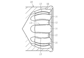
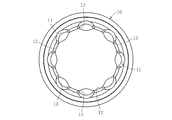
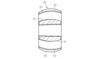
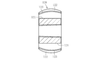
- FIG. 2 is a cross-sectional view taken along line AA in FIG. It is a longitudinal cross-sectional view which shows the outer joint member of the constant velocity universal joint of FIG. It is a right view which shows the outer joint member of the constant velocity universal joint of FIG. It is a longitudinal cross-sectional view which shows the inner side coupling member of the constant velocity universal joint of FIG. It is a right view which shows the inner side coupling member of the constant velocity universal joint of FIG. It is a longitudinal section showing the whole double offset type constant velocity universal joint composition in an embodiment of the present invention.
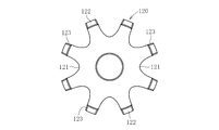
- FIG. 6 is a cross-sectional view taken along line BB in FIG. 5.
- Embodiments of the constant velocity universal joint according to the present invention will be described in detail below.
- a ball type Rzeppa constant velocity universal joint (BJ) using a ball as a torque transmitting member is illustrated, but an undercut free type constant velocity universal joint is used as another ball type fixed constant velocity universal joint.
- the present invention can be applied to a joint (UJ), and can also be applied to a double offset type constant velocity universal joint (DOJ) as another ball type sliding constant velocity universal joint.
- DOJ double offset type constant velocity universal joint
- a case where the present invention is applied to an eight-ball constant velocity universal joint is illustrated, but it is effective for eight or more multi-ball constant velocity universal joints.
- the Zepper type constant velocity universal joint includes an outer joint member 10 in which eight arc-shaped track grooves 11 extending in the axial direction are formed on the spherical inner peripheral surface 12 at equal intervals in the circumferential direction. And an inner joint member 20 in which eight arc-shaped track grooves 21 are formed on the spherical outer peripheral surface 22 in pairs with the track grooves 11 of the outer joint member 10, and the track grooves 11 and the inner joint of the outer joint member 10. Between the eight balls 30 as torque transmitting members interposed between the track grooves 21 of the member 20 and the spherical inner peripheral surface 12 of the outer joint member 10 and the spherical outer peripheral surface 22 of the inner joint member 20.
- the main part is composed of the cage 40 which is arranged and holds the ball 30.
- the outer joint member 10 constituting the constant velocity universal joint has a track chamfer at a track edge portion which is a boundary portion between the track groove 11 and the spherical inner peripheral surface 12 on both sides thereof. 13 is provided. 4A and 4B, the inner joint member 20 is provided with a track chamfer 23 at a track edge portion that is a boundary portion between the track groove 21 and the spherical outer peripheral surface 22 on both sides thereof.
- the track chamfers 13 and 23 are for relaxing stress concentration at the track edge portion, and may be either flat tapered surfaces or convex R curved surfaces, and their cross-sectional shapes are arbitrary.
- the surface hardness of the track chamfers 13 and 23 is made smaller than the surface hardness of the track grooves 11 and 21. Normally, the surface hardness of the track grooves 11 and 21 is about HRC 61 to 63, whereas the surface hardness of the track chamfers 13 and 23 is defined in the range of HRC 56 to 60.
- the ball 30 is the outer joint member at high load. Even if it runs on the track chamfers 13 and 23 which are the boundary between the track groove 11 and the inner peripheral surface 10 and the boundary between the track groove 21 and the outer peripheral surface 22 of the inner joint member 20, the track chamfers 13 and 23 As a result of the softening, the ball 30 is less likely to be damaged due to the interference between the ball 30 and the track chamfers 13 and 23 during the ride.
- the surface hardness of the track chamfers 13 and 23 within the range of HRC 56 to 60, it is possible to reliably prevent the balls 30 from being damaged due to the interference between the balls 30 and the track chamfers 13 and 23 when riding. Can do. If the surface hardness of the track chamfers 13 and 23 is smaller than the HRC 56, the track chamfers 13 and 23 become too soft, and the strength of the track chamfers becomes insufficient. On the other hand, if the surface hardness of the track chamfers 13 and 23 is higher than the HRC 60, the track chamfers 13 and 23 become too hard, so that the balls 30 are easily damaged when riding.
- the outer joint member and the inner joint member are heat-treated so that the surface hardness of the track chamfers 13, 23 is smaller than the surface hardness of the track grooves 11, 21, What is necessary is just to prescribe
- the entire track groove 11 and inner peripheral surface 12 of the outer joint member 10 and the entire track groove 21 and outer peripheral surface 22 of the inner joint member 20 are continuously patterned by normal carburizing or induction quenching and tempering.
- the surface hardness required for the track grooves 11 and the inner peripheral surface 12 of the outer joint member 10 and the track grooves 21 and the outer peripheral surface 22 of the inner joint member 20, for example, about HRC 63, is ensured.
- partial surface hardness is controlled by adopting an induction temper method in the tempering process. That is, the surface hardness of the track chamfers 13 and 23 is lowered and set in the range of HRC 56 to 60 by partially increasing the tempering amount in the track chamfers 13 and 23 by induction tempering tempering.
- the track groove 11 and the inner peripheral surface 12 of the outer joint member 10 and the track groove 21 and the outer peripheral surface 22 of the inner joint member 20 are quenched in a discontinuous pattern by induction hardening and tempering.
- the surface hardness of the track chamfers 13 and 23 is set in the range of HRC56-60.
- the entire track groove 11 and inner peripheral surface 12 of the outer joint member 10 and the entire track groove 21 and outer peripheral surface 22 of the inner joint member 20 are continuously patterned by normal carburizing or induction quenching and tempering.
- the surface hardness required for the track grooves 11 and the inner peripheral surface 12 of the outer joint member 10 and the track grooves 21 and the outer peripheral surface 22 of the inner joint member 20, for example, about HRC 63, is ensured.
- the surface hardened layer of the track chamfers 13 and 23 is removed by applying machining by finishing such as hardened steel cutting or grinding, so that the surface hardness of the track chamfers 13 and 23 is set in the range of HRC56-60. .
- both the track chamfer 13 of the outer joint member 10 and the track chamfer 23 of the inner joint member 20 have the surface hardness of the track chamfers 13 and 23 smaller than the surface hardness of the track grooves 11 and 21.
- the surface hardness of only one of the track chamfer 13 of the outer joint member 10 or the track chamfer 23 of the inner joint member 20 may be made smaller than the surface hardness of the track grooves 11 and 21.
- the double offset type constant velocity universal joint is an outer joint member in which eight linear track grooves 111 extending in the axial direction are formed on the cylindrical inner peripheral surface 112 at equal intervals in the circumferential direction. 110, an inner joint member 120 in which eight linear track grooves 121 are formed on the spherical outer peripheral surface 122 in a pair with the track groove 111 of the outer joint member 110, and the track groove 111 and the inner side of the outer joint member 110. Between the eight balls 130 as torque transmission members interposed between the track grooves 121 of the joint member 120, and the cylindrical inner peripheral surface 112 of the outer joint member 110 and the spherical outer peripheral surface 122 of the inner joint member 120. And a cage 140 that holds the ball 130 and constitutes a main part.
- the outer joint member 110 constituting the constant velocity universal joint has a track chamfer at a track edge portion which is a boundary portion between the track groove 111 and the cylindrical inner peripheral surface 112 on both sides thereof. 113 is provided. Further, as shown in FIGS. 8A and 8B, the inner joint member 120 is provided with a track chamfer 123 at a track edge portion that is a boundary portion between the track groove 121 and the spherical outer peripheral surface 122 on both sides thereof.
- the surface hardness of the track chamfers 113, 123 is made smaller than the surface hardness of the track grooves 111, 121.
- the numerical ranges of the surface hardness of the track chamfers 113 and 123 and the surface hardness of the track grooves 111 and 121 and methods such as heat treatment for setting the surface hardness of the embodiment of the above-mentioned Zepper type constant velocity universal joint, Since it is the same as that of a case, duplication description is abbreviate
Abstract
軸方向に延びるトラック溝11が内周面12の複数箇所に形成された外側継手部材10と、軸方向に延びるトラック溝21が外側継手部材10のトラック溝11と対をなして外周面22の複数箇所に形成された内側継手部材20と、外側継手部材10のトラック溝11と内側継手部材20のトラック溝21との間に介在するボール30とを備えた等速自在継手であって、外側継手部材10のトラック溝11と内周面12との境界部、および内側継手部材20のトラック溝21と外周面22との境界部にトラックチャンファ13,23を設け、外側継手部材10あるいは内側継手部材20の少なくとも一方のトラックチャンファ13,23の表面硬度をトラック溝11,21の表面硬度よりも小さくする。
Description
本発明は、自動車、航空機、船舶や各種産業機械の動力伝達系において使用され、例えば4WD車やFR車などで使用されるドライブシャフトやプロペラシャフト等に組み込まれる等速自在継手およびその製造方法に関する。
例えば、自動車のエンジンから車輪に回転力を等速で伝達する手段として使用される等速自在継手には、固定式等速自在継手と摺動式等速自在継手の二種がある。これら両者の等速自在継手は、駆動側と従動側の二軸を連結してその二軸が作動角をとっても等速で回転トルクを伝達し得る構造を備えている。
自動車のエンジンから駆動車輪に動力を伝達するドライブシャフトは、エンジンと車輪との相対的位置関係の変化による角度変位と軸方向変位に対応する必要があるため、一般的にエンジン側(インボード側)に摺動式等速自在継手を、駆動車輪側(アウトボード側)に固定式等速自在継手をそれぞれ装備し、両者の等速自在継手を中間シャフトで連結した構造を具備する。
これら固定式等速自在継手あるいは摺動式等速自在継手は、軸方向に延びるトラック溝が内周面の複数箇所に形成された外側継手部材と、軸方向に延びるトラック溝が外側継手部材のトラック溝と対をなして外周面の複数箇所に形成された内側継手部材と、外側継手部材のトラック溝と内側継手部材のトラック溝との間に介在するトルク伝達部材とを備えた構造が一般的である。
固定式等速自在継手には、トルク伝達部材としてボールを用いたボールタイプのツェッパ型等速自在継手(BJ)やアンダーカットフリー型等速自在継手(UJ)があり、また、摺動式等速自在継手には、トルク伝達部材としてボールを用いたボールタイプのダブルオフセット型等速自在継手(DOJ)がある。これら等速自在継手では、6個ボールのものが一般的であった。
ところで、近年では、軽量でコンパクトな等速自在継手の要望が高いことから、ボールの個数を増加させることでボール1個当りの負荷を軽減し、ボール径を小さくすることでコンパクト化を実現容易にした8個ボールの等速自在継手が提案されている。
この8個ボールの等速自在継手のようにコンパクトな多数個ボールの等速自在継手において、高負荷時での耐久性の向上および寿命ばらつきの安定化を図るため、ボールPCDすきまなどの内部寸法仕様を規制することで対応したものがある(例えば、特許文献1参照)。
しかしながら、前述したようなコンパクトな多数個ボールの等速自在継手では、ボール径を小さくすることで外側継手部材および内側継手部材のトラック溝の深さが小さくなる。この場合、高負荷時にボールがトラック溝からトラックエッジ部(外側継手部材の場合はトラック溝と内周面との境界部、また、内側継手部材の場合はトラック溝と外周面との境界部)へ乗り上げる現象が発生し易くなる。
この乗り上げた場合には、ボールとトラックエッジ部との干渉によるボールの傷付きが等速自在継手の寿命低下に影響する。
そこで、本発明は前述の問題点に鑑みて提案されたもので、その目的とするところは、高負荷時に発生するボールのトラックエッジ部への乗り上げた場合でも、それに起因する寿命の低下を抑制し得る等速自在継手およびその製造方法を提供することにある。
前述の目的を達成するための技術的手段として、本発明は、軸方向に延びるトラック溝が内周面の複数箇所に形成された外側継手部材と、軸方向に延びるトラック溝が外側継手部材のトラック溝と対をなして外周面の複数箇所に形成された内側継手部材と、外側継手部材のトラック溝と内側継手部材のトラック溝との間に介在するトルク伝達部材とを備えた等速自在継手であって、外側継手部材のトラック溝と内周面との境界部、および内側継手部材のトラック溝と外周面との境界部にトラックチャンファを設け、外側継手部材あるいは内側継手部材の少なくとも一方のトラックチャンファの表面硬度をトラック溝の表面硬度よりも小さくしたことを特徴とする。
ここで、「外側継手部材あるいは内側継手部材の少なくとも一方のトラックチャンファ」とは、外側継手部材のトラックチャンファのみの場合、内側継手部材のトラックチャンファのみの場合、外側継手部材のトラックチャンファと内側継手部材のトラックチャンファの両方の場合を含むことを意味する。
本発明は、球面状内周面に円弧状トラック溝が形成された外側継手部材と、球面状外周面に円弧状トラック溝が形成された内側継手部材と、外側継手部材の球面状内周面と内側継手部材の球面状外周面との間に配されたケージにより保持されたトルク伝達部材であるボールとで構成された固定式等速自在継手、例えばツェッパ型やアンダーカットフリー型等速自在継手に適用すれば有効である。
また、本発明は、円筒状内周面に直線状トラック溝が形成された外側継手部材と、球面状外周面に直線状トラック溝が形成された内側継手部材と、外側継手部材の円筒状内周面と内側継手部材の球面状外周面との間に配されたケージにより保持されたトルク伝達部材であるボールとで構成された摺動式等速自在継手、例えばダブルオフセット型等速自在継手にも適用可能である。
さらに、本発明におけるボールの個数は8個以上であることが望ましい。このような多数個ボールの等速自在継手の場合、ボール径が小さくなることで外側継手部材および内側継手部材のトラック溝の深さが小さくなり、ボールの乗り上げ現象が発生し易くなる点で有効である。
本発明では、外側継手部材のトラック溝と内周面との境界部、および内側継手部材のトラック溝と外周面との境界部に設けられたトラックチャンファのうち、少なくとも一方のトラックチャンファの表面硬度をトラック溝の表面硬度よりも小さくしたことにより、コンパクトな多数個ボールの等速自在継手において、高負荷時にボールが外側継手部材あるいは内側継手部材のトラックチャンファへ乗り上げても、この乗り上げ時のボールとトラックチャンファとの干渉によるボールの傷付きが発生し難くなる。
本発明において、トラックチャンファの表面硬度をHRC56~60の範囲に規定することが望ましい。このような範囲にトラックチャンファの表面硬度を規定すれば、乗り上げ時のボールとトラックチャンファとの干渉によるボールの傷付きを確実に発生し難くすることができる。なお、トラックチャンファの表面硬度がHRC56よりも小さいと、そのトラックチャンファが柔らかくなり過ぎることから、トラックチャンファの強度不足となる。逆に、トラックチャンファの表面硬度がHRC60よりも大きいと、そのトラックチャンファが硬くなり過ぎることから、乗り上げ時のボールの傷付きが発生し易くなる。
本発明は、軸方向に延びるトラック溝が内周面の複数箇所に形成された外側継手部材と、軸方向に延びるトラック溝が外側継手部材のトラック溝と対をなして外周面の複数箇所に形成された内側継手部材と、外側継手部材のトラック溝と内側継手部材のトラック溝との間に介在するトルク伝達部材とを備えた等速自在継手の製造方法であって、外側継手部材のトラック溝と内周面との境界部および内側継手部材のトラック溝と外周面との境界部に設けられたトラックチャンファのうち、少なくとも一方のトラックチャンファの表面硬度がトラック溝の表面硬度よりも小さくなるように、外側継手部材および内側継手部材を熱処理することを特徴とする。
本発明方法において、トラックチャンファの表面硬度は、外側継手部材のトラック溝および内周面、内側継手部材のトラック溝および外周面を連続的なパターンで焼入れした後、その焼戻し工程でトラックチャンファでの焼戻し量を大きくすることにより設定することが可能である。また、外側継手部材のトラック溝および内周面、内側継手部材のトラック溝および外周面を非連続的なパターンで焼入れすることにより、トラックチャンファを除く部位を焼入れすることにより設定することも可能である。さらに、外側継手部材のトラック溝および内周面、内側継手部材のトラック溝および外周面を連続的なパターンで焼入れした後、トラックチャンファの表面硬化層を除去することにより設定することも可能である。このように、トラックチャンファの表面硬度は、熱処理および機械加工の組合せにより適宜設定可能である。
本発明によれば、外側継手部材のトラック溝と内周面との境界部、および内側継手部材のトラック溝と外周面との境界部に設けられたトラックチャンファのうち、少なくとも一方のトラックチャンファの表面硬度をトラック溝の表面硬度よりも小さくしたことにより、コンパクトな多数個ボールの等速自在継手において、高負荷時にボールがトラックチャンファへ乗り上げても、この乗り上げ時のボールとトラックチャンファとの干渉によるボールの傷付きが発生し難くなる。その結果、高負荷時に発生するボールのトラックチャンファへの乗り上げに起因する寿命の低下を抑制することができるので、信頼性の高い長寿命の等速自在継手を提供できる。
本発明に係る等速自在継手の実施形態を以下に詳述する。以下の実施形態では、トルク伝達部材としてボールを用いたボールタイプのツェッパ型等速自在継手(BJ)を例示するが、他のボールタイプの固定式等速自在継手としてアンダーカットフリー型等速自在継手(UJ)にも適用可能であり、さらに、他のボールタイプの摺動式等速自在継手としてダブルオフセット型等速自在継手(DOJ)にも適用可能である。また、以下の実施形態では、8個ボールの等速自在継手に適用した場合を例示するが、8個以上の多数個ボールの等速自在継手に対して有効である。
図1および図2に示す実施形態のツェッパ型等速自在継手は、軸方向に延びる8つの円弧状トラック溝11が球面状内周面12に円周方向等間隔で形成された外側継手部材10と、その外側継手部材10のトラック溝11と対をなして8つの円弧状トラック溝21が球面状外周面22に形成された内側継手部材20と、外側継手部材10のトラック溝11と内側継手部材20のトラック溝21との間に介在するトルク伝達部材としての8個のボール30と、外側継手部材10の球面状内周面12と内側継手部材20の球面状外周面22との間に配されてボール30を保持するケージ40とで主要部が構成されている。
この等速自在継手を構成する外側継手部材10は、図3Aおよび図3Bに示すように、トラック溝11とその両側にある球面状内周面12との境界部であるトラックエッジ部にトラックチャンファ13が設けられている。また、内側継手部材20は、図4Aおよび図4Bに示すように、トラック溝21とその両側にある球面状外周面22との境界部であるトラックエッジ部にトラックチャンファ23が設けられている。このトラックチャンファ13,23は、トラックエッジ部での応力集中を緩和するためのものであり、平坦なテーパ面状あるいは凸R曲面状のいずれであってもよく、その断面形状は任意である。
この実施形態におけるツェッパ型等速自在継手において、トラックチャンファ13,23の表面硬度をトラック溝11,21の表面硬度よりも小さくする。通常、トラック溝11,21の表面硬度がHRC61~63程度であるのに対して、トラックチャンファ13,23の表面硬度をHRC56~60の範囲に規定する。
このように、トラックチャンファ13,23の表面硬度をトラック溝11,21の表面硬度よりも小さくしたことにより、コンパクトな8個ボール30の等速自在継手において、高負荷時にボール30が外側継手部材10のトラック溝11と内周面12との境界部、および内側継手部材20のトラック溝21と外周面22との境界部であるトラックチャンファ13,23へ乗り上げても、そのトラックチャンファ13,23を柔らかくしたことで、この乗り上げ時のボール30とトラックチャンファ13,23との干渉によるボール30の傷付きが発生し難くなる。
特に、トラックチャンファ13,23の表面硬度をHRC56~60の範囲に規定することにより、乗り上げ時のボール30とトラックチャンファ13,23との干渉によるボール30の傷付きを確実に発生し難くすることができる。なお、トラックチャンファ13,23の表面硬度がHRC56よりも小さいと、そのトラックチャンファ13,23が柔らかくなり過ぎることから、トラックチャンファの強度不足となる。逆に、トラックチャンファ13,23の表面硬度がHRC60よりも大きいと、そのトラックチャンファ13,23が硬くなり過ぎることから、乗り上げ時のボール30の傷付きが発生し易くなる。
以上の実施形態のように、トラックチャンファ13,23の表面硬度がトラック溝11,21の表面硬度よりも小さくなるように、外側継手部材および内側継手部材を熱処理することになるが、その場合、以下のような手法により、トラックチャンファの表面硬度をHRC56~60の範囲に規定すればよい。
まず、第一の手法として、通常の浸炭あるいは高周波焼入れ焼戻しにより、外側継手部材10のトラック溝11および内周面12、内側継手部材20のトラック溝21および外周面22の全体を連続的なパターンで焼入れすることにより、外側継手部材10のトラック溝11および内周面12、内側継手部材20のトラック溝21および外周面22で必要とする表面硬度、例えばHRC63程度を確保する。その後、焼戻し工程で誘導テンパー方式を採用することにより部分的な表面硬度のコントロールを行う。つまり、誘導テンパー方式の焼戻しにより、トラックチャンファ13,23での焼戻し量を部分的に大きくすることにより、トラックチャンファ13,23の表面硬度を低下させてHRC56~60の範囲に設定する。
また、第二の手法として、高周波焼入れ焼戻しにより、外側継手部材10のトラック溝11および内周面12、内側継手部材20のトラック溝21および外周面22を非連続的なパターンで焼入れすることにより、トラックチャンファ13,23を除く部位を焼入れすることにより、トラックチャンファ13,23の表面硬度をHRC56~60の範囲に設定する。
さらに、第三の手法として、通常の浸炭あるいは高周波焼入れ焼戻しにより、外側継手部材10のトラック溝11および内周面12、内側継手部材20のトラック溝21および外周面22の全体を連続的なパターンで焼入れすることにより、外側継手部材10のトラック溝11および内周面12、内側継手部材20のトラック溝21および外周面22で必要とする表面硬度、例えばHRC63程度を確保する。その後、トラックチャンファ13,23の表面硬化層を焼入れ鋼切削や研削などの仕上げ加工による機械加工を加えることで除去することにより、トラックチャンファ13,23の表面硬度をHRC56~60の範囲に設定する。
以上の実施形態では、外側継手部材10のトラックチャンファ13および内側継手部材20のトラックチャンファ23の両方について、それらトラックチャンファ13,23の表面硬度をトラック溝11,21の表面硬度よりも小さくした場合について説明したが、外側継手部材10のトラックチャンファ13あるいは内側継手部材20のトラックチャンファ23のいずれか一方のみの表面硬度をトラック溝11,21の表面硬度よりも小さくするだけでもよい。
以上の実施形態では、固定式等速自在継手の一つであるツェッパ型等速自在継手に適用した場合を例示したが、本発明はこれに限定されることなく、摺動式等速自在継手の一つであるダブルオフセット型等速自在継手にも適用可能である。
ダブルオフセット型等速自在継手は、図5および図6に示すように、軸方向に延びる8つの直線状トラック溝111が円筒状内周面112に円周方向等間隔で形成された外側継手部材110と、その外側継手部材110のトラック溝111と対をなして8つの直線状トラック溝121が球面状外周面122に形成された内側継手部材120と、外側継手部材110のトラック溝111と内側継手部材120のトラック溝121との間に介在するトルク伝達部材としての8個のボール130と、外側継手部材110の円筒状内周面112と内側継手部材120の球面状外周面122との間に配されてボール130を保持するケージ140とで主要部が構成されている。
この等速自在継手を構成する外側継手部材110は、図7Aおよび図7Bに示すように、トラック溝111とその両側にある円筒状内周面112との境界部であるトラックエッジ部にトラックチャンファ113が設けられている。また、内側継手部材120は、図8Aおよび図8Bに示すように、トラック溝121とその両側にある球面状外周面122との境界部であるトラックエッジ部にトラックチャンファ123が設けられている。
このダブルオフセット型等速自在継手に適用した実施形態において、トラックチャンファ113,123の表面硬度をトラック溝111,121の表面硬度よりも小さくする。そのトラックチャンファ113,123の表面硬度およびトラック溝111,121の表面硬度の数値範囲や、その表面硬度を設定するための熱処理などの手法については、前述のツェッパ型等速自在継手の実施形態の場合と同様であるため、重複説明は省略する。
本発明は前述した実施形態に何ら限定されるものではなく、本発明の要旨を逸脱しない範囲内において、さらに種々なる形態で実施し得ることは勿論のことであり、本発明の範囲は、特許請求の範囲によって示され、さらに特許請求の範囲に記載の均等の意味、および範囲内のすべての変更を含む。
Claims (9)
- 軸方向に延びるトラック溝が内周面の複数箇所に形成された外側継手部材と、軸方向に延びるトラック溝が前記外側継手部材のトラック溝と対をなして外周面の複数箇所に形成された内側継手部材と、前記外側継手部材のトラック溝と前記内側継手部材のトラック溝との間に介在するトルク伝達部材とを備えた等速自在継手であって、
前記外側継手部材のトラック溝と内周面との境界部、および前記内側継手部材のトラック溝と外周面との境界部にトラックチャンファを設け、前記外側継手部材あるいは内側継手部材の少なくとも一方のトラックチャンファの表面硬度を前記トラック溝の表面硬度よりも小さくしたことを特徴とする等速自在継手。 - 前記トラックチャンファの表面硬度をHRC56~60の範囲に規定した請求項1に記載の等速自在継手。
- 前記外側継手部材は球面状内周面に円弧状トラック溝が形成され、前記内側継手部材は球面状外周面に円弧状トラック溝が形成され、前記トルク伝達部材は、外側継手部材の球面状内周面と内側継手部材の球面状外周面との間に配されたケージにより保持されたボールである請求項1又は2に記載の等速自在継手。
- 前記外側継手部材は円筒状内周面に直線状トラック溝が形成され、前記内側継手部材は球面状外周面に直線状トラック溝が形成され、前記トルク伝達部材は、外側継手部材の円筒状内周面と内側継手部材の球面状外周面との間に配されたケージにより保持されたボールである請求項1又は2に記載の等速自在継手。
- 前記ボールの個数は8個以上である請求項3又は4に記載の等速自在継手。
- 軸方向に延びるトラック溝が内周面の複数箇所に形成された外側継手部材と、軸方向に延びるトラック溝が前記外側継手部材のトラック溝と対をなして外周面の複数箇所に形成された内側継手部材と、前記外側継手部材のトラック溝と前記内側継手部材のトラック溝との間に介在するトルク伝達部材とを備えた等速自在継手の製造方法において、
前記外側継手部材のトラック溝と内周面との境界部、および前記内側継手部材のトラック溝と外周面との境界部に設けられたトラックチャンファのうち、少なくとも一方のトラックチャンファの表面硬度が前記トラック溝の表面硬度よりも小さくなるように、前記外側継手部材および内側継手部材を熱処理することを特徴とする等速自在継手の製造方法。 - 前記トラックチャンファの表面硬度は、外側継手部材のトラック溝および内周面、内側継手部材のトラック溝および外周面を連続的なパターンで焼入れした後、その焼戻し工程でトラックチャンファでの焼戻し量を大きくすることにより設定されている請求項6に記載の等速自在継手の製造方法。
- 前記トラックチャンファの表面硬度は、外側継手部材のトラック溝および内周面、内側継手部材のトラック溝および外周面を非連続的なパターンで焼入れすることにより、トラックチャンファを除く部位を焼入れすることにより設定されている請求項6に記載の等速自在継手の製造方法。
- 前記トラックチャンファの表面硬度は、外側継手部材のトラック溝および内周面、内側継手部材のトラック溝および外周面を連続的なパターンで焼入れした後、トラックチャンファの表面硬化層を除去することにより設定されている請求項6に記載の等速自在継手の製造方法。
Priority Applications (3)
| Application Number | Priority Date | Filing Date | Title |
|---|---|---|---|
| CN201280041029.3A CN103748375B (zh) | 2011-08-22 | 2012-08-22 | 等速万向接头及其制造方法 |
| EP12825052.9A EP2749783B1 (en) | 2011-08-22 | 2012-08-22 | Constant velocity universal joint and method for producing same |
| US14/238,260 US9291207B2 (en) | 2011-08-22 | 2012-08-22 | Constant velocity universal joint and method for producing same |
Applications Claiming Priority (2)
| Application Number | Priority Date | Filing Date | Title |
|---|---|---|---|
| JP2011180575A JP5766548B2 (ja) | 2011-08-22 | 2011-08-22 | 等速自在継手およびその製造方法 |
| JP2011-180575 | 2011-08-22 |
Publications (1)
| Publication Number | Publication Date |
|---|---|
| WO2013027763A1 true WO2013027763A1 (ja) | 2013-02-28 |
Family
ID=47746501
Family Applications (1)
| Application Number | Title | Priority Date | Filing Date |
|---|---|---|---|
| PCT/JP2012/071196 WO2013027763A1 (ja) | 2011-08-22 | 2012-08-22 | 等速自在継手およびその製造方法 |
Country Status (5)
| Country | Link |
|---|---|
| US (1) | US9291207B2 (ja) |
| EP (1) | EP2749783B1 (ja) |
| JP (1) | JP5766548B2 (ja) |
| CN (1) | CN103748375B (ja) |
| WO (1) | WO2013027763A1 (ja) |
Cited By (1)
| Publication number | Priority date | Publication date | Assignee | Title |
|---|---|---|---|---|
| EP3088762A4 (en) * | 2013-12-24 | 2017-01-25 | NTN Corporation | Rotation transmission device |
Families Citing this family (1)
| Publication number | Priority date | Publication date | Assignee | Title |
|---|---|---|---|---|
| JP2017020543A (ja) * | 2015-07-08 | 2017-01-26 | Ntn株式会社 | 固定式等速自在継手 |
Citations (3)
| Publication number | Priority date | Publication date | Assignee | Title |
|---|---|---|---|---|
| JP2009097629A (ja) * | 2007-10-17 | 2009-05-07 | Ntn Corp | 等速自在継手用外側継手部材及び固定式等速自在継手 |
| JP2009121673A (ja) * | 2007-10-22 | 2009-06-04 | Ntn Corp | 等速自在継手 |
| JP2011133107A (ja) * | 2009-11-26 | 2011-07-07 | Ntn Corp | 固定型等速自在継手 |
Family Cites Families (11)
| Publication number | Priority date | Publication date | Assignee | Title |
|---|---|---|---|---|
| JP3424035B2 (ja) * | 1994-10-26 | 2003-07-07 | Ntn株式会社 | 等速ボールジョイントの外輪 |
| JP4193344B2 (ja) * | 2000-08-22 | 2008-12-10 | 日本精工株式会社 | 車輪用駆動ユニット |
| JP4041657B2 (ja) | 2001-04-24 | 2008-01-30 | Ntn株式会社 | 等速自在継手 |
| JP2005098450A (ja) * | 2003-09-26 | 2005-04-14 | Ntn Corp | 等速自在継手の外側継手部材およびその製造方法 |
| DE112004001207B4 (de) * | 2004-10-01 | 2013-07-25 | Gkn Driveline International Gmbh | Verfahren zur Herstellung eines Gelenks mit hochbelastbarem Innenteil |
| JP2008002624A (ja) | 2006-06-23 | 2008-01-10 | Ntn Corp | 等速自在継手及びこれを用いたドライブシャフト、駆動車輪用軸受ユニット |
| JP2008008475A (ja) | 2006-06-30 | 2008-01-17 | Ntn Corp | 摺動式等速自在継手 |
| DE102007031078B4 (de) * | 2006-07-05 | 2021-02-04 | Neumayer Tekfor Engineering Gmbh | Kugelgleichlauffestgelenk als Gegenbahngelenk und Verfahren zur Herstellung |
| US8029374B2 (en) | 2006-09-14 | 2011-10-04 | Ntn Corporation | Fixed constant-velocity universal joint |
| JP5398965B2 (ja) * | 2007-06-04 | 2014-01-29 | Ntn株式会社 | 固定式等速自在継手 |
| US8172962B2 (en) * | 2007-06-04 | 2012-05-08 | Ntn Corporation | Fixed constant velocity universal joint and method for manufacturing outer race thereof |
-
2011
- 2011-08-22 JP JP2011180575A patent/JP5766548B2/ja not_active Expired - Fee Related
-
2012
- 2012-08-22 US US14/238,260 patent/US9291207B2/en not_active Expired - Fee Related
- 2012-08-22 WO PCT/JP2012/071196 patent/WO2013027763A1/ja active Application Filing
- 2012-08-22 CN CN201280041029.3A patent/CN103748375B/zh not_active Expired - Fee Related
- 2012-08-22 EP EP12825052.9A patent/EP2749783B1/en not_active Not-in-force
Patent Citations (3)
| Publication number | Priority date | Publication date | Assignee | Title |
|---|---|---|---|---|
| JP2009097629A (ja) * | 2007-10-17 | 2009-05-07 | Ntn Corp | 等速自在継手用外側継手部材及び固定式等速自在継手 |
| JP2009121673A (ja) * | 2007-10-22 | 2009-06-04 | Ntn Corp | 等速自在継手 |
| JP2011133107A (ja) * | 2009-11-26 | 2011-07-07 | Ntn Corp | 固定型等速自在継手 |
Cited By (2)
| Publication number | Priority date | Publication date | Assignee | Title |
|---|---|---|---|---|
| EP3088762A4 (en) * | 2013-12-24 | 2017-01-25 | NTN Corporation | Rotation transmission device |
| US10184531B2 (en) | 2013-12-24 | 2019-01-22 | Ntn Corporation | Rotation transmission device |
Also Published As
| Publication number | Publication date |
|---|---|
| EP2749783B1 (en) | 2019-04-10 |
| CN103748375B (zh) | 2016-09-07 |
| CN103748375A (zh) | 2014-04-23 |
| JP5766548B2 (ja) | 2015-08-19 |
| JP2013044348A (ja) | 2013-03-04 |
| EP2749783A1 (en) | 2014-07-02 |
| US9291207B2 (en) | 2016-03-22 |
| US20140221108A1 (en) | 2014-08-07 |
| EP2749783A4 (en) | 2016-07-20 |
Similar Documents
| Publication | Publication Date | Title |
|---|---|---|
| US8313587B2 (en) | Method for producing a torque transmission device useful as a fixed constant velocity ball joint for drive shafts | |
| US7651400B2 (en) | Constant velocity universal joint and inner member thereof | |
| US8388456B2 (en) | Fixed-type, constant-velocity universal joint | |
| US9816565B2 (en) | Cage for constant velocity universal joint, fixed type constant velocity universal joint incorporating same, and drive shaft incorporating said fixed type constant velocity universal joint | |
| JP2009121673A (ja) | 等速自在継手 | |
| JP5766548B2 (ja) | 等速自在継手およびその製造方法 | |
| JP2007139094A (ja) | 等速自在継手 | |
| EP2202422B1 (en) | Constant velocity universal joint | |
| JP2010043691A (ja) | 等速自在継手およびその製造方法 | |
| JP5398965B2 (ja) | 固定式等速自在継手 | |
| JP2007170423A (ja) | 等速自在継手及びその内方部材 | |
| JP2007162874A (ja) | 等速自在継手及びその内方部材 | |
| JP2007002943A (ja) | 等速自在継手及びその内方部材 | |
| JP5133395B2 (ja) | 不整地走行用の鞍乗り型車両用ドライブシャフトおよびそれに用いるアンダーカットフリー型等速自在継手の製造方法 | |
| JP2000104749A (ja) | 固定式等速ジョイント | |
| JP2007064265A (ja) | 等速自在継手及びその内方部材 | |
| JP2010159775A (ja) | 摺動式等速自在継手 | |
| JP2010001951A (ja) | 等速自在継手用外方部材及びその製造方法 | |
| JP2011208674A (ja) | 等速自在継手 | |
| JP2009085327A (ja) | しゅう動式等速自在継手およびその外側継手部材 | |
| JP2007162875A (ja) | 等速自在継手及びその内方部材 | |
| JP2008304006A (ja) | 固定式等速自在継手およびその外輪の製造方法 | |
| WO2007097156A1 (ja) | 等速自在継手及びそのケージ | |
| JP2010019344A (ja) | 摺動式等速自在継手 | |
| JP2009174660A (ja) | 等速自在継手のケージ、プロペラシャフトアッセンブリー、およびドライブシャフトアッセンブリー |
Legal Events
| Date | Code | Title | Description |
|---|---|---|---|
| 121 | Ep: the epo has been informed by wipo that ep was designated in this application |
Ref document number: 12825052 Country of ref document: EP Kind code of ref document: A1 |
|
| WWE | Wipo information: entry into national phase |
Ref document number: 14238260 Country of ref document: US |
|
| NENP | Non-entry into the national phase |
Ref country code: DE |