WO2013021997A1 - 制御装置 - Google Patents
制御装置 Download PDFInfo
- Publication number
- WO2013021997A1 WO2013021997A1 PCT/JP2012/070094 JP2012070094W WO2013021997A1 WO 2013021997 A1 WO2013021997 A1 WO 2013021997A1 JP 2012070094 W JP2012070094 W JP 2012070094W WO 2013021997 A1 WO2013021997 A1 WO 2013021997A1
- Authority
- WO
- WIPO (PCT)
- Prior art keywords
- rotational speed
- target
- temperature
- power generation
- electrical machine
- Prior art date
- Legal status (The legal status is an assumption and is not a legal conclusion. Google has not performed a legal analysis and makes no representation as to the accuracy of the status listed.)
- Ceased
Links
Images





Classifications
-
- B—PERFORMING OPERATIONS; TRANSPORTING
- B60—VEHICLES IN GENERAL
- B60W—CONJOINT CONTROL OF VEHICLE SUB-UNITS OF DIFFERENT TYPE OR DIFFERENT FUNCTION; CONTROL SYSTEMS SPECIALLY ADAPTED FOR HYBRID VEHICLES; ROAD VEHICLE DRIVE CONTROL SYSTEMS FOR PURPOSES NOT RELATED TO THE CONTROL OF A PARTICULAR SUB-UNIT
- B60W20/00—Control systems specially adapted for hybrid vehicles
- B60W20/10—Controlling the power contribution of each of the prime movers to meet required power demand
-
- B—PERFORMING OPERATIONS; TRANSPORTING
- B60—VEHICLES IN GENERAL
- B60W—CONJOINT CONTROL OF VEHICLE SUB-UNITS OF DIFFERENT TYPE OR DIFFERENT FUNCTION; CONTROL SYSTEMS SPECIALLY ADAPTED FOR HYBRID VEHICLES; ROAD VEHICLE DRIVE CONTROL SYSTEMS FOR PURPOSES NOT RELATED TO THE CONTROL OF A PARTICULAR SUB-UNIT
- B60W10/00—Conjoint control of vehicle sub-units of different type or different function
- B60W10/04—Conjoint control of vehicle sub-units of different type or different function including control of propulsion units
- B60W10/08—Conjoint control of vehicle sub-units of different type or different function including control of propulsion units including control of electric propulsion units, e.g. motors or generators
-
- B—PERFORMING OPERATIONS; TRANSPORTING
- B60—VEHICLES IN GENERAL
- B60K—ARRANGEMENT OR MOUNTING OF PROPULSION UNITS OR OF TRANSMISSIONS IN VEHICLES; ARRANGEMENT OR MOUNTING OF PLURAL DIVERSE PRIME-MOVERS IN VEHICLES; AUXILIARY DRIVES FOR VEHICLES; INSTRUMENTATION OR DASHBOARDS FOR VEHICLES; ARRANGEMENTS IN CONNECTION WITH COOLING, AIR INTAKE, GAS EXHAUST OR FUEL SUPPLY OF PROPULSION UNITS IN VEHICLES
- B60K6/00—Arrangement or mounting of plural diverse prime-movers for mutual or common propulsion, e.g. hybrid propulsion systems comprising electric motors and internal combustion engines
- B60K6/20—Arrangement or mounting of plural diverse prime-movers for mutual or common propulsion, e.g. hybrid propulsion systems comprising electric motors and internal combustion engines the prime-movers consisting of electric motors and internal combustion engines, e.g. HEVs
- B60K6/22—Arrangement or mounting of plural diverse prime-movers for mutual or common propulsion, e.g. hybrid propulsion systems comprising electric motors and internal combustion engines the prime-movers consisting of electric motors and internal combustion engines, e.g. HEVs characterised by apparatus, components or means specially adapted for HEVs
- B60K6/38—Arrangement or mounting of plural diverse prime-movers for mutual or common propulsion, e.g. hybrid propulsion systems comprising electric motors and internal combustion engines the prime-movers consisting of electric motors and internal combustion engines, e.g. HEVs characterised by apparatus, components or means specially adapted for HEVs characterised by the driveline clutches
- B60K6/387—Actuated clutches, i.e. clutches engaged or disengaged by electric, hydraulic or mechanical actuating means
-
- B—PERFORMING OPERATIONS; TRANSPORTING
- B60—VEHICLES IN GENERAL
- B60K—ARRANGEMENT OR MOUNTING OF PROPULSION UNITS OR OF TRANSMISSIONS IN VEHICLES; ARRANGEMENT OR MOUNTING OF PLURAL DIVERSE PRIME-MOVERS IN VEHICLES; AUXILIARY DRIVES FOR VEHICLES; INSTRUMENTATION OR DASHBOARDS FOR VEHICLES; ARRANGEMENTS IN CONNECTION WITH COOLING, AIR INTAKE, GAS EXHAUST OR FUEL SUPPLY OF PROPULSION UNITS IN VEHICLES
- B60K6/00—Arrangement or mounting of plural diverse prime-movers for mutual or common propulsion, e.g. hybrid propulsion systems comprising electric motors and internal combustion engines
- B60K6/20—Arrangement or mounting of plural diverse prime-movers for mutual or common propulsion, e.g. hybrid propulsion systems comprising electric motors and internal combustion engines the prime-movers consisting of electric motors and internal combustion engines, e.g. HEVs
- B60K6/42—Arrangement or mounting of plural diverse prime-movers for mutual or common propulsion, e.g. hybrid propulsion systems comprising electric motors and internal combustion engines the prime-movers consisting of electric motors and internal combustion engines, e.g. HEVs characterised by the architecture of the hybrid electric vehicle
- B60K6/48—Parallel type
-
- B—PERFORMING OPERATIONS; TRANSPORTING
- B60—VEHICLES IN GENERAL
- B60K—ARRANGEMENT OR MOUNTING OF PROPULSION UNITS OR OF TRANSMISSIONS IN VEHICLES; ARRANGEMENT OR MOUNTING OF PLURAL DIVERSE PRIME-MOVERS IN VEHICLES; AUXILIARY DRIVES FOR VEHICLES; INSTRUMENTATION OR DASHBOARDS FOR VEHICLES; ARRANGEMENTS IN CONNECTION WITH COOLING, AIR INTAKE, GAS EXHAUST OR FUEL SUPPLY OF PROPULSION UNITS IN VEHICLES
- B60K6/00—Arrangement or mounting of plural diverse prime-movers for mutual or common propulsion, e.g. hybrid propulsion systems comprising electric motors and internal combustion engines
- B60K6/20—Arrangement or mounting of plural diverse prime-movers for mutual or common propulsion, e.g. hybrid propulsion systems comprising electric motors and internal combustion engines the prime-movers consisting of electric motors and internal combustion engines, e.g. HEVs
- B60K6/50—Architecture of the driveline characterised by arrangement or kind of transmission units
- B60K6/54—Transmission for changing ratio
- B60K6/547—Transmission for changing ratio the transmission being a stepped gearing
-
- B—PERFORMING OPERATIONS; TRANSPORTING
- B60—VEHICLES IN GENERAL
- B60L—PROPULSION OF ELECTRICALLY-PROPELLED VEHICLES; SUPPLYING ELECTRIC POWER FOR AUXILIARY EQUIPMENT OF ELECTRICALLY-PROPELLED VEHICLES; ELECTRODYNAMIC BRAKE SYSTEMS FOR VEHICLES IN GENERAL; MAGNETIC SUSPENSION OR LEVITATION FOR VEHICLES; MONITORING OPERATING VARIABLES OF ELECTRICALLY-PROPELLED VEHICLES; ELECTRIC SAFETY DEVICES FOR ELECTRICALLY-PROPELLED VEHICLES
- B60L15/00—Methods, circuits, or devices for controlling the traction-motor speed of electrically-propelled vehicles
- B60L15/20—Methods, circuits, or devices for controlling the traction-motor speed of electrically-propelled vehicles for control of the vehicle or its driving motor to achieve a desired performance, e.g. speed, torque, programmed variation of speed
-
- B—PERFORMING OPERATIONS; TRANSPORTING
- B60—VEHICLES IN GENERAL
- B60L—PROPULSION OF ELECTRICALLY-PROPELLED VEHICLES; SUPPLYING ELECTRIC POWER FOR AUXILIARY EQUIPMENT OF ELECTRICALLY-PROPELLED VEHICLES; ELECTRODYNAMIC BRAKE SYSTEMS FOR VEHICLES IN GENERAL; MAGNETIC SUSPENSION OR LEVITATION FOR VEHICLES; MONITORING OPERATING VARIABLES OF ELECTRICALLY-PROPELLED VEHICLES; ELECTRIC SAFETY DEVICES FOR ELECTRICALLY-PROPELLED VEHICLES
- B60L15/00—Methods, circuits, or devices for controlling the traction-motor speed of electrically-propelled vehicles
- B60L15/20—Methods, circuits, or devices for controlling the traction-motor speed of electrically-propelled vehicles for control of the vehicle or its driving motor to achieve a desired performance, e.g. speed, torque, programmed variation of speed
- B60L15/2009—Methods, circuits, or devices for controlling the traction-motor speed of electrically-propelled vehicles for control of the vehicle or its driving motor to achieve a desired performance, e.g. speed, torque, programmed variation of speed for braking
-
- B—PERFORMING OPERATIONS; TRANSPORTING
- B60—VEHICLES IN GENERAL
- B60L—PROPULSION OF ELECTRICALLY-PROPELLED VEHICLES; SUPPLYING ELECTRIC POWER FOR AUXILIARY EQUIPMENT OF ELECTRICALLY-PROPELLED VEHICLES; ELECTRODYNAMIC BRAKE SYSTEMS FOR VEHICLES IN GENERAL; MAGNETIC SUSPENSION OR LEVITATION FOR VEHICLES; MONITORING OPERATING VARIABLES OF ELECTRICALLY-PROPELLED VEHICLES; ELECTRIC SAFETY DEVICES FOR ELECTRICALLY-PROPELLED VEHICLES
- B60L15/00—Methods, circuits, or devices for controlling the traction-motor speed of electrically-propelled vehicles
- B60L15/20—Methods, circuits, or devices for controlling the traction-motor speed of electrically-propelled vehicles for control of the vehicle or its driving motor to achieve a desired performance, e.g. speed, torque, programmed variation of speed
- B60L15/2054—Methods, circuits, or devices for controlling the traction-motor speed of electrically-propelled vehicles for control of the vehicle or its driving motor to achieve a desired performance, e.g. speed, torque, programmed variation of speed by controlling transmissions or clutches
-
- B—PERFORMING OPERATIONS; TRANSPORTING
- B60—VEHICLES IN GENERAL
- B60L—PROPULSION OF ELECTRICALLY-PROPELLED VEHICLES; SUPPLYING ELECTRIC POWER FOR AUXILIARY EQUIPMENT OF ELECTRICALLY-PROPELLED VEHICLES; ELECTRODYNAMIC BRAKE SYSTEMS FOR VEHICLES IN GENERAL; MAGNETIC SUSPENSION OR LEVITATION FOR VEHICLES; MONITORING OPERATING VARIABLES OF ELECTRICALLY-PROPELLED VEHICLES; ELECTRIC SAFETY DEVICES FOR ELECTRICALLY-PROPELLED VEHICLES
- B60L3/00—Electric devices on electrically-propelled vehicles for safety purposes; Monitoring operating variables, e.g. speed, deceleration or energy consumption
- B60L3/0023—Detecting, eliminating, remedying or compensating for drive train abnormalities, e.g. failures within the drive train
- B60L3/003—Detecting, eliminating, remedying or compensating for drive train abnormalities, e.g. failures within the drive train relating to inverters
-
- B—PERFORMING OPERATIONS; TRANSPORTING
- B60—VEHICLES IN GENERAL
- B60L—PROPULSION OF ELECTRICALLY-PROPELLED VEHICLES; SUPPLYING ELECTRIC POWER FOR AUXILIARY EQUIPMENT OF ELECTRICALLY-PROPELLED VEHICLES; ELECTRODYNAMIC BRAKE SYSTEMS FOR VEHICLES IN GENERAL; MAGNETIC SUSPENSION OR LEVITATION FOR VEHICLES; MONITORING OPERATING VARIABLES OF ELECTRICALLY-PROPELLED VEHICLES; ELECTRIC SAFETY DEVICES FOR ELECTRICALLY-PROPELLED VEHICLES
- B60L3/00—Electric devices on electrically-propelled vehicles for safety purposes; Monitoring operating variables, e.g. speed, deceleration or energy consumption
- B60L3/0023—Detecting, eliminating, remedying or compensating for drive train abnormalities, e.g. failures within the drive train
- B60L3/0061—Detecting, eliminating, remedying or compensating for drive train abnormalities, e.g. failures within the drive train relating to electrical machines
-
- B—PERFORMING OPERATIONS; TRANSPORTING
- B60—VEHICLES IN GENERAL
- B60L—PROPULSION OF ELECTRICALLY-PROPELLED VEHICLES; SUPPLYING ELECTRIC POWER FOR AUXILIARY EQUIPMENT OF ELECTRICALLY-PROPELLED VEHICLES; ELECTRODYNAMIC BRAKE SYSTEMS FOR VEHICLES IN GENERAL; MAGNETIC SUSPENSION OR LEVITATION FOR VEHICLES; MONITORING OPERATING VARIABLES OF ELECTRICALLY-PROPELLED VEHICLES; ELECTRIC SAFETY DEVICES FOR ELECTRICALLY-PROPELLED VEHICLES
- B60L50/00—Electric propulsion with power supplied within the vehicle
- B60L50/10—Electric propulsion with power supplied within the vehicle using propulsion power supplied by engine-driven generators, e.g. generators driven by combustion engines
- B60L50/16—Electric propulsion with power supplied within the vehicle using propulsion power supplied by engine-driven generators, e.g. generators driven by combustion engines with provision for separate direct mechanical propulsion
-
- B—PERFORMING OPERATIONS; TRANSPORTING
- B60—VEHICLES IN GENERAL
- B60L—PROPULSION OF ELECTRICALLY-PROPELLED VEHICLES; SUPPLYING ELECTRIC POWER FOR AUXILIARY EQUIPMENT OF ELECTRICALLY-PROPELLED VEHICLES; ELECTRODYNAMIC BRAKE SYSTEMS FOR VEHICLES IN GENERAL; MAGNETIC SUSPENSION OR LEVITATION FOR VEHICLES; MONITORING OPERATING VARIABLES OF ELECTRICALLY-PROPELLED VEHICLES; ELECTRIC SAFETY DEVICES FOR ELECTRICALLY-PROPELLED VEHICLES
- B60L7/00—Electrodynamic brake systems for vehicles in general
- B60L7/10—Dynamic electric regenerative braking
- B60L7/14—Dynamic electric regenerative braking for vehicles propelled by AC motors
-
- B—PERFORMING OPERATIONS; TRANSPORTING
- B60—VEHICLES IN GENERAL
- B60W—CONJOINT CONTROL OF VEHICLE SUB-UNITS OF DIFFERENT TYPE OR DIFFERENT FUNCTION; CONTROL SYSTEMS SPECIALLY ADAPTED FOR HYBRID VEHICLES; ROAD VEHICLE DRIVE CONTROL SYSTEMS FOR PURPOSES NOT RELATED TO THE CONTROL OF A PARTICULAR SUB-UNIT
- B60W10/00—Conjoint control of vehicle sub-units of different type or different function
- B60W10/02—Conjoint control of vehicle sub-units of different type or different function including control of driveline clutches
-
- B—PERFORMING OPERATIONS; TRANSPORTING
- B60—VEHICLES IN GENERAL
- B60W—CONJOINT CONTROL OF VEHICLE SUB-UNITS OF DIFFERENT TYPE OR DIFFERENT FUNCTION; CONTROL SYSTEMS SPECIALLY ADAPTED FOR HYBRID VEHICLES; ROAD VEHICLE DRIVE CONTROL SYSTEMS FOR PURPOSES NOT RELATED TO THE CONTROL OF A PARTICULAR SUB-UNIT
- B60W10/00—Conjoint control of vehicle sub-units of different type or different function
- B60W10/04—Conjoint control of vehicle sub-units of different type or different function including control of propulsion units
- B60W10/06—Conjoint control of vehicle sub-units of different type or different function including control of propulsion units including control of combustion engines
-
- B—PERFORMING OPERATIONS; TRANSPORTING
- B60—VEHICLES IN GENERAL
- B60W—CONJOINT CONTROL OF VEHICLE SUB-UNITS OF DIFFERENT TYPE OR DIFFERENT FUNCTION; CONTROL SYSTEMS SPECIALLY ADAPTED FOR HYBRID VEHICLES; ROAD VEHICLE DRIVE CONTROL SYSTEMS FOR PURPOSES NOT RELATED TO THE CONTROL OF A PARTICULAR SUB-UNIT
- B60W20/00—Control systems specially adapted for hybrid vehicles
-
- B—PERFORMING OPERATIONS; TRANSPORTING
- B60—VEHICLES IN GENERAL
- B60W—CONJOINT CONTROL OF VEHICLE SUB-UNITS OF DIFFERENT TYPE OR DIFFERENT FUNCTION; CONTROL SYSTEMS SPECIALLY ADAPTED FOR HYBRID VEHICLES; ROAD VEHICLE DRIVE CONTROL SYSTEMS FOR PURPOSES NOT RELATED TO THE CONTROL OF A PARTICULAR SUB-UNIT
- B60W20/00—Control systems specially adapted for hybrid vehicles
- B60W20/10—Controlling the power contribution of each of the prime movers to meet required power demand
- B60W20/13—Controlling the power contribution of each of the prime movers to meet required power demand in order to stay within battery power input or output limits; in order to prevent overcharging or battery depletion
-
- B—PERFORMING OPERATIONS; TRANSPORTING
- B60—VEHICLES IN GENERAL
- B60W—CONJOINT CONTROL OF VEHICLE SUB-UNITS OF DIFFERENT TYPE OR DIFFERENT FUNCTION; CONTROL SYSTEMS SPECIALLY ADAPTED FOR HYBRID VEHICLES; ROAD VEHICLE DRIVE CONTROL SYSTEMS FOR PURPOSES NOT RELATED TO THE CONTROL OF A PARTICULAR SUB-UNIT
- B60W20/00—Control systems specially adapted for hybrid vehicles
- B60W20/10—Controlling the power contribution of each of the prime movers to meet required power demand
- B60W20/15—Control strategies specially adapted for achieving a particular effect
-
- B—PERFORMING OPERATIONS; TRANSPORTING
- B60—VEHICLES IN GENERAL
- B60W—CONJOINT CONTROL OF VEHICLE SUB-UNITS OF DIFFERENT TYPE OR DIFFERENT FUNCTION; CONTROL SYSTEMS SPECIALLY ADAPTED FOR HYBRID VEHICLES; ROAD VEHICLE DRIVE CONTROL SYSTEMS FOR PURPOSES NOT RELATED TO THE CONTROL OF A PARTICULAR SUB-UNIT
- B60W30/00—Purposes of road vehicle drive control systems not related to the control of a particular sub-unit, e.g. of systems using conjoint control of vehicle sub-units
- B60W30/18—Propelling the vehicle
- B60W30/184—Preventing damage resulting from overload or excessive wear of the driveline
- B60W30/1843—Overheating of driveline components
-
- H—ELECTRICITY
- H02—GENERATION; CONVERSION OR DISTRIBUTION OF ELECTRIC POWER
- H02P—CONTROL OR REGULATION OF ELECTRIC MOTORS, ELECTRIC GENERATORS OR DYNAMO-ELECTRIC CONVERTERS; CONTROLLING TRANSFORMERS, REACTORS OR CHOKE COILS
- H02P29/00—Arrangements for regulating or controlling electric motors, appropriate for both AC and DC motors
- H02P29/60—Controlling or determining the temperature of the motor or of the drive
- H02P29/68—Controlling or determining the temperature of the motor or of the drive based on the temperature of a drive component or a semiconductor component
-
- H—ELECTRICITY
- H02—GENERATION; CONVERSION OR DISTRIBUTION OF ELECTRIC POWER
- H02P—CONTROL OR REGULATION OF ELECTRIC MOTORS, ELECTRIC GENERATORS OR DYNAMO-ELECTRIC CONVERTERS; CONTROLLING TRANSFORMERS, REACTORS OR CHOKE COILS
- H02P3/00—Arrangements for stopping or slowing electric motors, generators, or dynamo-electric converters
- H02P3/06—Arrangements for stopping or slowing electric motors, generators, or dynamo-electric converters for stopping or slowing an individual dynamo-electric motor or dynamo-electric converter
-
- B—PERFORMING OPERATIONS; TRANSPORTING
- B60—VEHICLES IN GENERAL
- B60K—ARRANGEMENT OR MOUNTING OF PROPULSION UNITS OR OF TRANSMISSIONS IN VEHICLES; ARRANGEMENT OR MOUNTING OF PLURAL DIVERSE PRIME-MOVERS IN VEHICLES; AUXILIARY DRIVES FOR VEHICLES; INSTRUMENTATION OR DASHBOARDS FOR VEHICLES; ARRANGEMENTS IN CONNECTION WITH COOLING, AIR INTAKE, GAS EXHAUST OR FUEL SUPPLY OF PROPULSION UNITS IN VEHICLES
- B60K6/00—Arrangement or mounting of plural diverse prime-movers for mutual or common propulsion, e.g. hybrid propulsion systems comprising electric motors and internal combustion engines
- B60K6/20—Arrangement or mounting of plural diverse prime-movers for mutual or common propulsion, e.g. hybrid propulsion systems comprising electric motors and internal combustion engines the prime-movers consisting of electric motors and internal combustion engines, e.g. HEVs
- B60K6/42—Arrangement or mounting of plural diverse prime-movers for mutual or common propulsion, e.g. hybrid propulsion systems comprising electric motors and internal combustion engines the prime-movers consisting of electric motors and internal combustion engines, e.g. HEVs characterised by the architecture of the hybrid electric vehicle
- B60K6/48—Parallel type
- B60K2006/4825—Electric machine connected or connectable to gearbox input shaft
-
- B—PERFORMING OPERATIONS; TRANSPORTING
- B60—VEHICLES IN GENERAL
- B60L—PROPULSION OF ELECTRICALLY-PROPELLED VEHICLES; SUPPLYING ELECTRIC POWER FOR AUXILIARY EQUIPMENT OF ELECTRICALLY-PROPELLED VEHICLES; ELECTRODYNAMIC BRAKE SYSTEMS FOR VEHICLES IN GENERAL; MAGNETIC SUSPENSION OR LEVITATION FOR VEHICLES; MONITORING OPERATING VARIABLES OF ELECTRICALLY-PROPELLED VEHICLES; ELECTRIC SAFETY DEVICES FOR ELECTRICALLY-PROPELLED VEHICLES
- B60L2210/00—Converter types
- B60L2210/40—DC to AC converters
-
- B—PERFORMING OPERATIONS; TRANSPORTING
- B60—VEHICLES IN GENERAL
- B60L—PROPULSION OF ELECTRICALLY-PROPELLED VEHICLES; SUPPLYING ELECTRIC POWER FOR AUXILIARY EQUIPMENT OF ELECTRICALLY-PROPELLED VEHICLES; ELECTRODYNAMIC BRAKE SYSTEMS FOR VEHICLES IN GENERAL; MAGNETIC SUSPENSION OR LEVITATION FOR VEHICLES; MONITORING OPERATING VARIABLES OF ELECTRICALLY-PROPELLED VEHICLES; ELECTRIC SAFETY DEVICES FOR ELECTRICALLY-PROPELLED VEHICLES
- B60L2240/00—Control parameters of input or output; Target parameters
- B60L2240/10—Vehicle control parameters
- B60L2240/12—Speed
-
- B—PERFORMING OPERATIONS; TRANSPORTING
- B60—VEHICLES IN GENERAL
- B60L—PROPULSION OF ELECTRICALLY-PROPELLED VEHICLES; SUPPLYING ELECTRIC POWER FOR AUXILIARY EQUIPMENT OF ELECTRICALLY-PROPELLED VEHICLES; ELECTRODYNAMIC BRAKE SYSTEMS FOR VEHICLES IN GENERAL; MAGNETIC SUSPENSION OR LEVITATION FOR VEHICLES; MONITORING OPERATING VARIABLES OF ELECTRICALLY-PROPELLED VEHICLES; ELECTRIC SAFETY DEVICES FOR ELECTRICALLY-PROPELLED VEHICLES
- B60L2240/00—Control parameters of input or output; Target parameters
- B60L2240/10—Vehicle control parameters
- B60L2240/36—Temperature of vehicle components or parts
-
- B—PERFORMING OPERATIONS; TRANSPORTING
- B60—VEHICLES IN GENERAL
- B60L—PROPULSION OF ELECTRICALLY-PROPELLED VEHICLES; SUPPLYING ELECTRIC POWER FOR AUXILIARY EQUIPMENT OF ELECTRICALLY-PROPELLED VEHICLES; ELECTRODYNAMIC BRAKE SYSTEMS FOR VEHICLES IN GENERAL; MAGNETIC SUSPENSION OR LEVITATION FOR VEHICLES; MONITORING OPERATING VARIABLES OF ELECTRICALLY-PROPELLED VEHICLES; ELECTRIC SAFETY DEVICES FOR ELECTRICALLY-PROPELLED VEHICLES
- B60L2240/00—Control parameters of input or output; Target parameters
- B60L2240/40—Drive Train control parameters
- B60L2240/42—Drive Train control parameters related to electric machines
- B60L2240/421—Speed
-
- B—PERFORMING OPERATIONS; TRANSPORTING
- B60—VEHICLES IN GENERAL
- B60L—PROPULSION OF ELECTRICALLY-PROPELLED VEHICLES; SUPPLYING ELECTRIC POWER FOR AUXILIARY EQUIPMENT OF ELECTRICALLY-PROPELLED VEHICLES; ELECTRODYNAMIC BRAKE SYSTEMS FOR VEHICLES IN GENERAL; MAGNETIC SUSPENSION OR LEVITATION FOR VEHICLES; MONITORING OPERATING VARIABLES OF ELECTRICALLY-PROPELLED VEHICLES; ELECTRIC SAFETY DEVICES FOR ELECTRICALLY-PROPELLED VEHICLES
- B60L2240/00—Control parameters of input or output; Target parameters
- B60L2240/40—Drive Train control parameters
- B60L2240/42—Drive Train control parameters related to electric machines
- B60L2240/423—Torque
-
- B—PERFORMING OPERATIONS; TRANSPORTING
- B60—VEHICLES IN GENERAL
- B60L—PROPULSION OF ELECTRICALLY-PROPELLED VEHICLES; SUPPLYING ELECTRIC POWER FOR AUXILIARY EQUIPMENT OF ELECTRICALLY-PROPELLED VEHICLES; ELECTRODYNAMIC BRAKE SYSTEMS FOR VEHICLES IN GENERAL; MAGNETIC SUSPENSION OR LEVITATION FOR VEHICLES; MONITORING OPERATING VARIABLES OF ELECTRICALLY-PROPELLED VEHICLES; ELECTRIC SAFETY DEVICES FOR ELECTRICALLY-PROPELLED VEHICLES
- B60L2240/00—Control parameters of input or output; Target parameters
- B60L2240/40—Drive Train control parameters
- B60L2240/42—Drive Train control parameters related to electric machines
- B60L2240/425—Temperature
-
- B—PERFORMING OPERATIONS; TRANSPORTING
- B60—VEHICLES IN GENERAL
- B60L—PROPULSION OF ELECTRICALLY-PROPELLED VEHICLES; SUPPLYING ELECTRIC POWER FOR AUXILIARY EQUIPMENT OF ELECTRICALLY-PROPELLED VEHICLES; ELECTRODYNAMIC BRAKE SYSTEMS FOR VEHICLES IN GENERAL; MAGNETIC SUSPENSION OR LEVITATION FOR VEHICLES; MONITORING OPERATING VARIABLES OF ELECTRICALLY-PROPELLED VEHICLES; ELECTRIC SAFETY DEVICES FOR ELECTRICALLY-PROPELLED VEHICLES
- B60L2240/00—Control parameters of input or output; Target parameters
- B60L2240/40—Drive Train control parameters
- B60L2240/44—Drive Train control parameters related to combustion engines
- B60L2240/441—Speed
-
- B—PERFORMING OPERATIONS; TRANSPORTING
- B60—VEHICLES IN GENERAL
- B60L—PROPULSION OF ELECTRICALLY-PROPELLED VEHICLES; SUPPLYING ELECTRIC POWER FOR AUXILIARY EQUIPMENT OF ELECTRICALLY-PROPELLED VEHICLES; ELECTRODYNAMIC BRAKE SYSTEMS FOR VEHICLES IN GENERAL; MAGNETIC SUSPENSION OR LEVITATION FOR VEHICLES; MONITORING OPERATING VARIABLES OF ELECTRICALLY-PROPELLED VEHICLES; ELECTRIC SAFETY DEVICES FOR ELECTRICALLY-PROPELLED VEHICLES
- B60L2240/00—Control parameters of input or output; Target parameters
- B60L2240/40—Drive Train control parameters
- B60L2240/44—Drive Train control parameters related to combustion engines
- B60L2240/443—Torque
-
- B—PERFORMING OPERATIONS; TRANSPORTING
- B60—VEHICLES IN GENERAL
- B60L—PROPULSION OF ELECTRICALLY-PROPELLED VEHICLES; SUPPLYING ELECTRIC POWER FOR AUXILIARY EQUIPMENT OF ELECTRICALLY-PROPELLED VEHICLES; ELECTRODYNAMIC BRAKE SYSTEMS FOR VEHICLES IN GENERAL; MAGNETIC SUSPENSION OR LEVITATION FOR VEHICLES; MONITORING OPERATING VARIABLES OF ELECTRICALLY-PROPELLED VEHICLES; ELECTRIC SAFETY DEVICES FOR ELECTRICALLY-PROPELLED VEHICLES
- B60L2240/00—Control parameters of input or output; Target parameters
- B60L2240/40—Drive Train control parameters
- B60L2240/48—Drive Train control parameters related to transmissions
- B60L2240/486—Operating parameters
-
- B—PERFORMING OPERATIONS; TRANSPORTING
- B60—VEHICLES IN GENERAL
- B60L—PROPULSION OF ELECTRICALLY-PROPELLED VEHICLES; SUPPLYING ELECTRIC POWER FOR AUXILIARY EQUIPMENT OF ELECTRICALLY-PROPELLED VEHICLES; ELECTRODYNAMIC BRAKE SYSTEMS FOR VEHICLES IN GENERAL; MAGNETIC SUSPENSION OR LEVITATION FOR VEHICLES; MONITORING OPERATING VARIABLES OF ELECTRICALLY-PROPELLED VEHICLES; ELECTRIC SAFETY DEVICES FOR ELECTRICALLY-PROPELLED VEHICLES
- B60L2240/00—Control parameters of input or output; Target parameters
- B60L2240/40—Drive Train control parameters
- B60L2240/50—Drive Train control parameters related to clutches
- B60L2240/507—Operating parameters
-
- B—PERFORMING OPERATIONS; TRANSPORTING
- B60—VEHICLES IN GENERAL
- B60L—PROPULSION OF ELECTRICALLY-PROPELLED VEHICLES; SUPPLYING ELECTRIC POWER FOR AUXILIARY EQUIPMENT OF ELECTRICALLY-PROPELLED VEHICLES; ELECTRODYNAMIC BRAKE SYSTEMS FOR VEHICLES IN GENERAL; MAGNETIC SUSPENSION OR LEVITATION FOR VEHICLES; MONITORING OPERATING VARIABLES OF ELECTRICALLY-PROPELLED VEHICLES; ELECTRIC SAFETY DEVICES FOR ELECTRICALLY-PROPELLED VEHICLES
- B60L2240/00—Control parameters of input or output; Target parameters
- B60L2240/40—Drive Train control parameters
- B60L2240/52—Drive Train control parameters related to converters
- B60L2240/525—Temperature of converter or components thereof
-
- B—PERFORMING OPERATIONS; TRANSPORTING
- B60—VEHICLES IN GENERAL
- B60L—PROPULSION OF ELECTRICALLY-PROPELLED VEHICLES; SUPPLYING ELECTRIC POWER FOR AUXILIARY EQUIPMENT OF ELECTRICALLY-PROPELLED VEHICLES; ELECTRODYNAMIC BRAKE SYSTEMS FOR VEHICLES IN GENERAL; MAGNETIC SUSPENSION OR LEVITATION FOR VEHICLES; MONITORING OPERATING VARIABLES OF ELECTRICALLY-PROPELLED VEHICLES; ELECTRIC SAFETY DEVICES FOR ELECTRICALLY-PROPELLED VEHICLES
- B60L2240/00—Control parameters of input or output; Target parameters
- B60L2240/40—Drive Train control parameters
- B60L2240/54—Drive Train control parameters related to batteries
- B60L2240/545—Temperature
-
- B—PERFORMING OPERATIONS; TRANSPORTING
- B60—VEHICLES IN GENERAL
- B60L—PROPULSION OF ELECTRICALLY-PROPELLED VEHICLES; SUPPLYING ELECTRIC POWER FOR AUXILIARY EQUIPMENT OF ELECTRICALLY-PROPELLED VEHICLES; ELECTRODYNAMIC BRAKE SYSTEMS FOR VEHICLES IN GENERAL; MAGNETIC SUSPENSION OR LEVITATION FOR VEHICLES; MONITORING OPERATING VARIABLES OF ELECTRICALLY-PROPELLED VEHICLES; ELECTRIC SAFETY DEVICES FOR ELECTRICALLY-PROPELLED VEHICLES
- B60L2250/00—Driver interactions
- B60L2250/26—Driver interactions by pedal actuation
-
- B—PERFORMING OPERATIONS; TRANSPORTING
- B60—VEHICLES IN GENERAL
- B60W—CONJOINT CONTROL OF VEHICLE SUB-UNITS OF DIFFERENT TYPE OR DIFFERENT FUNCTION; CONTROL SYSTEMS SPECIALLY ADAPTED FOR HYBRID VEHICLES; ROAD VEHICLE DRIVE CONTROL SYSTEMS FOR PURPOSES NOT RELATED TO THE CONTROL OF A PARTICULAR SUB-UNIT
- B60W2510/00—Input parameters relating to a particular sub-units
- B60W2510/06—Combustion engines, Gas turbines
- B60W2510/0638—Engine speed
-
- B—PERFORMING OPERATIONS; TRANSPORTING
- B60—VEHICLES IN GENERAL
- B60W—CONJOINT CONTROL OF VEHICLE SUB-UNITS OF DIFFERENT TYPE OR DIFFERENT FUNCTION; CONTROL SYSTEMS SPECIALLY ADAPTED FOR HYBRID VEHICLES; ROAD VEHICLE DRIVE CONTROL SYSTEMS FOR PURPOSES NOT RELATED TO THE CONTROL OF A PARTICULAR SUB-UNIT
- B60W2510/00—Input parameters relating to a particular sub-units
- B60W2510/08—Electric propulsion units
- B60W2510/081—Speed
-
- B—PERFORMING OPERATIONS; TRANSPORTING
- B60—VEHICLES IN GENERAL
- B60W—CONJOINT CONTROL OF VEHICLE SUB-UNITS OF DIFFERENT TYPE OR DIFFERENT FUNCTION; CONTROL SYSTEMS SPECIALLY ADAPTED FOR HYBRID VEHICLES; ROAD VEHICLE DRIVE CONTROL SYSTEMS FOR PURPOSES NOT RELATED TO THE CONTROL OF A PARTICULAR SUB-UNIT
- B60W2510/00—Input parameters relating to a particular sub-units
- B60W2510/08—Electric propulsion units
- B60W2510/087—Temperature
-
- B—PERFORMING OPERATIONS; TRANSPORTING
- B60—VEHICLES IN GENERAL
- B60W—CONJOINT CONTROL OF VEHICLE SUB-UNITS OF DIFFERENT TYPE OR DIFFERENT FUNCTION; CONTROL SYSTEMS SPECIALLY ADAPTED FOR HYBRID VEHICLES; ROAD VEHICLE DRIVE CONTROL SYSTEMS FOR PURPOSES NOT RELATED TO THE CONTROL OF A PARTICULAR SUB-UNIT
- B60W2510/00—Input parameters relating to a particular sub-units
- B60W2510/24—Energy storage means
- B60W2510/242—Energy storage means for electrical energy
- B60W2510/244—Charge state
-
- B—PERFORMING OPERATIONS; TRANSPORTING
- B60—VEHICLES IN GENERAL
- B60W—CONJOINT CONTROL OF VEHICLE SUB-UNITS OF DIFFERENT TYPE OR DIFFERENT FUNCTION; CONTROL SYSTEMS SPECIALLY ADAPTED FOR HYBRID VEHICLES; ROAD VEHICLE DRIVE CONTROL SYSTEMS FOR PURPOSES NOT RELATED TO THE CONTROL OF A PARTICULAR SUB-UNIT
- B60W2710/00—Output or target parameters relating to a particular sub-units
- B60W2710/08—Electric propulsion units
- B60W2710/081—Speed
-
- Y—GENERAL TAGGING OF NEW TECHNOLOGICAL DEVELOPMENTS; GENERAL TAGGING OF CROSS-SECTIONAL TECHNOLOGIES SPANNING OVER SEVERAL SECTIONS OF THE IPC; TECHNICAL SUBJECTS COVERED BY FORMER USPC CROSS-REFERENCE ART COLLECTIONS [XRACs] AND DIGESTS
- Y02—TECHNOLOGIES OR APPLICATIONS FOR MITIGATION OR ADAPTATION AGAINST CLIMATE CHANGE
- Y02T—CLIMATE CHANGE MITIGATION TECHNOLOGIES RELATED TO TRANSPORTATION
- Y02T10/00—Road transport of goods or passengers
- Y02T10/60—Other road transportation technologies with climate change mitigation effect
- Y02T10/62—Hybrid vehicles
-
- Y—GENERAL TAGGING OF NEW TECHNOLOGICAL DEVELOPMENTS; GENERAL TAGGING OF CROSS-SECTIONAL TECHNOLOGIES SPANNING OVER SEVERAL SECTIONS OF THE IPC; TECHNICAL SUBJECTS COVERED BY FORMER USPC CROSS-REFERENCE ART COLLECTIONS [XRACs] AND DIGESTS
- Y02—TECHNOLOGIES OR APPLICATIONS FOR MITIGATION OR ADAPTATION AGAINST CLIMATE CHANGE
- Y02T—CLIMATE CHANGE MITIGATION TECHNOLOGIES RELATED TO TRANSPORTATION
- Y02T10/00—Road transport of goods or passengers
- Y02T10/60—Other road transportation technologies with climate change mitigation effect
- Y02T10/64—Electric machine technologies in electromobility
-
- Y—GENERAL TAGGING OF NEW TECHNOLOGICAL DEVELOPMENTS; GENERAL TAGGING OF CROSS-SECTIONAL TECHNOLOGIES SPANNING OVER SEVERAL SECTIONS OF THE IPC; TECHNICAL SUBJECTS COVERED BY FORMER USPC CROSS-REFERENCE ART COLLECTIONS [XRACs] AND DIGESTS
- Y02—TECHNOLOGIES OR APPLICATIONS FOR MITIGATION OR ADAPTATION AGAINST CLIMATE CHANGE
- Y02T—CLIMATE CHANGE MITIGATION TECHNOLOGIES RELATED TO TRANSPORTATION
- Y02T10/00—Road transport of goods or passengers
- Y02T10/60—Other road transportation technologies with climate change mitigation effect
- Y02T10/70—Energy storage systems for electromobility, e.g. batteries
-
- Y—GENERAL TAGGING OF NEW TECHNOLOGICAL DEVELOPMENTS; GENERAL TAGGING OF CROSS-SECTIONAL TECHNOLOGIES SPANNING OVER SEVERAL SECTIONS OF THE IPC; TECHNICAL SUBJECTS COVERED BY FORMER USPC CROSS-REFERENCE ART COLLECTIONS [XRACs] AND DIGESTS
- Y02—TECHNOLOGIES OR APPLICATIONS FOR MITIGATION OR ADAPTATION AGAINST CLIMATE CHANGE
- Y02T—CLIMATE CHANGE MITIGATION TECHNOLOGIES RELATED TO TRANSPORTATION
- Y02T10/00—Road transport of goods or passengers
- Y02T10/60—Other road transportation technologies with climate change mitigation effect
- Y02T10/7072—Electromobility specific charging systems or methods for batteries, ultracapacitors, supercapacitors or double-layer capacitors
-
- Y—GENERAL TAGGING OF NEW TECHNOLOGICAL DEVELOPMENTS; GENERAL TAGGING OF CROSS-SECTIONAL TECHNOLOGIES SPANNING OVER SEVERAL SECTIONS OF THE IPC; TECHNICAL SUBJECTS COVERED BY FORMER USPC CROSS-REFERENCE ART COLLECTIONS [XRACs] AND DIGESTS
- Y02—TECHNOLOGIES OR APPLICATIONS FOR MITIGATION OR ADAPTATION AGAINST CLIMATE CHANGE
- Y02T—CLIMATE CHANGE MITIGATION TECHNOLOGIES RELATED TO TRANSPORTATION
- Y02T10/00—Road transport of goods or passengers
- Y02T10/60—Other road transportation technologies with climate change mitigation effect
- Y02T10/72—Electric energy management in electromobility
Definitions
- the present invention provides a power transmission path that connects an input member that is drivingly connected to an internal combustion engine and an output member that is drivingly connected to a wheel, from the input member side to the first engagement device, the rotating electrical machine, and the second engagement.
- the present invention relates to a control device that controls a vehicle drive device provided in the order of devices.
- a drive device for a hybrid vehicle including an internal combustion engine and a rotating electrical machine as a drive force source for example, a device described in Patent Document 1 below is already known.
- This hybrid vehicle is not provided with an element that absorbs the rotational speed of the driving force source unlike a torque converter.
- the first engagement device and the second engagement device provided in the drive device are slipped at the time of starting the vehicle, traveling at an extremely low speed, starting the internal combustion engine, or the like. It is configured to be able to transmit the driving force even if there is a rotational speed difference between the rotational speed of each driving force source and the rotational speed of the wheel by controlling to the engaged state.
- Patent Document 1 is configured to control the first engagement device to the sliding engagement state in addition to the second engagement device.
- the rotational speed of the rotating electrical machine is reduced relative to the rotational speed of the internal combustion engine by the amount of slip of the first engagement device, and the slip amount of the second engagement device is reduced.
- the amount of heat generated by the second engagement device is reduced by a decrease in the slip amount of the second engagement device, and deterioration of the second engagement device due to overheating can be suppressed.
- a power transmission path that connects an input member that is drivingly connected to an internal combustion engine and an output member that is drivingly connected to a wheel to a power transmission path from the input member side, a first engagement device, a rotating electrical machine, and a second engagement.
- the characteristic configuration of the control device that controls the vehicle drive device provided in the order of the combined device is that both the first engagement device and the second engagement device are in a sliding engagement state, and the rotating electrical machine
- a power generation rotational speed control unit that executes power generation rotational speed control for controlling output torque of the rotating electrical machine so that the rotational speed of the rotating electrical machine approaches a target rotational speed in a state where power generation is in progress.
- the unit monitors at least one of the temperature of the rotating electrical machine and the temperature of the inverter as a monitoring target temperature, determines the target rotation speed based on the monitoring target temperature, and Certain amount of power generated by the rotary electric machine in rotation speed control point to execute the power generation amount maintaining control for maintaining the target power generation amount.
- the “rotary electric machine” is used as a concept including a motor (electric motor), a generator (generator), and a motor / generator that functions as both a motor and a generator as necessary.
- driving connection refers to a state where two rotating elements are connected so as to be able to transmit a driving force, and the two rotating elements are connected so as to rotate integrally, or It is used as a concept including a state in which two rotating elements are connected so as to be able to transmit a driving force via one or more transmission members.
- Such a transmission member examples include various members that transmit rotation at the same speed or a variable speed, and include, for example, a shaft, a gear mechanism, a belt, a chain, and the like. Further, as such a transmission member, an engagement device that selectively transmits rotation and driving force, for example, a friction engagement device or a meshing engagement device may be included.
- the power generation rotational speed control is executed while the rotating electrical machine is generating power and both the first engagement device and the second engagement device are in the sliding engagement state.
- the rotational speed of the rotating electrical machine is reduced below the rotational speed of the internal combustion engine by the difference in rotational speed between the engaging members of the first engagement device.
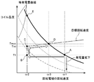
- the magnitude of the regenerative torque of the rotating electrical machine is increased in accordance with the amount of decrease in the rotational speed of the rotating electrical machine, and the power generation amount of the rotating electrical machine is reduced to the required target power generating capacity by the power generation maintaining control. Can be maintained.
- the temperature of the rotating electrical machine and the temperature of the inverter rise due to an increase in the magnitude of the regenerative torque.
- the target rotation speed of the rotating electrical machine is monitored as the monitoring target temperature, and the target rotation speed is determined based on the monitoring target temperature, thereby increasing the monitoring target temperature.
- the target rotational speed of the rotating electrical machine can be increased, and the magnitude of the regenerative torque can be reduced by the power generation amount maintenance control. Therefore, it is possible to suppress an increase in the temperature to be monitored while securing the required power generation amount, and it is possible to suppress overheating of the rotating electrical machine or the inverter (or both; the same applies hereinafter).
- the target rotational speed of the rotating electrical machine can be decreased and the amount of regenerative torque can be increased by the power generation amount maintenance control. That is, for example, the target rotational speed of the rotating electrical machine can be reduced within a range in which the rotating electrical machine or the inverter is not overheated, and the difference in rotational speed between the engaging members of the second engagement device is reduced to generate heat. Can be suppressed.
- the target rotation speed of the rotating electrical machine can be increased or decreased without changing the rotation speed of the internal combustion engine and the rotation speed of the wheels. Can do. Therefore, the controllability of the monitoring target temperature by the power generation rotation speed control can be enhanced.
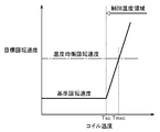
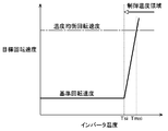
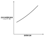
- the power generation rotation speed control unit determines the target rotation speed so that the target rotation speed becomes higher as the monitoring target temperature becomes higher. This is preferable.
- the target rotational speed is greatly increased and the regenerative torque is further reduced. Therefore, the higher the monitored temperature, the more effectively the amount of heat generated by the rotating electrical machine or inverter is reduced. Can be made. Therefore, the temperature rise can be more reliably suppressed as the monitoring target temperature increases. Therefore, it is possible to effectively suppress the monitoring target temperature from exceeding a predetermined temperature.
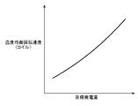
- the power generation rotational speed control unit is a rotational speed defined according to the target power generation amount when the monitoring target temperature reaches a predetermined allowable upper limit temperature, It is preferable to increase the target rotational speed to a temperature equilibrium rotational speed that is a rotational speed at which the monitored temperature does not exceed the allowable upper limit temperature regardless of the operation time.
- the rotational speed of the rotating electrical machine is increased to the temperature equilibrium rotational speed at which the monitoring target temperature constantly becomes the allowable upper limit temperature. Can be prevented from exceeding the allowable upper limit temperature. Therefore, the progress of deterioration of the rotating electrical machine or the inverter can be suppressed.
- the power generation rotational speed control unit determines a first target rotational speed based on the temperature of the rotating electrical machine and a second target rotational speed based on the temperature of the inverter, and the first target rotational speed and the second target rotational speed are determined. It is preferable that the target rotational speed is determined based on the higher of the target rotational speeds.
- the target rotational speed during the power generation amount maintaining control can be appropriately determined based on the temperature of the rotating electrical machine and the temperature of the inverter, and overheating of both the rotating electrical machine and the inverter can be suppressed.
- the power generation rotational speed control unit sets the lower limit rotational speed at which the target power generation amount can be secured to the target rotational speed when the monitoring target temperature is lower than a lower limit value of a predetermined control temperature region. It is preferable to determine.
- the rotation speed of the rotating electrical machine when the monitoring target temperature is less than the lower limit value, the rotation speed of the rotating electrical machine can be reduced to a lower limit that can ensure the target power generation amount, and between the engagement members of the second engagement device.
- the rotational speed difference can be reduced. Therefore, heat generation in the sliding engagement state of the second engagement device can be reduced, and overheating of the second engagement device can be suppressed.
- the power generation rotational speed control unit determines a target torque to be output to the rotating electrical machine based on the target rotational speed and the target power generation amount in the power generation amount maintenance control, and based on the target torque It is preferable to control at least one of the transmission torque of the first engagement device, the transmission torque of the second engagement device, and the output torque of the internal combustion engine.
- the transmission torque of the first engagement device by controlling any one or more of the transmission torque of the first engagement device, the transmission torque of the second engagement device, and the output torque of the internal combustion engine, it acts on the inertial system of the rotating electrical machine from the outside.
- the torque to be changed can be changed by the increase or decrease of the target torque to be output to the rotating electrical machine.
- the output torque of the rotating electrical machine is automatically increased or decreased by the increase or decrease of the target torque to be output to the rotating electrical machine by controlling the rotational speed of the rotating electrical machine. Is done. Therefore, the output torque of the rotating electrical machine can be changed by the increase or decrease of the target torque that should be indirectly output to the rotating electrical machine, and the power generation amount of the rotating electrical machine can be maintained at the target power generation amount.
- FIG. 1 is a schematic diagram showing a schematic configuration of a vehicle drive device 1 and a control device 30 according to the present embodiment.
- the solid line indicates the driving force transmission path
- the broken line indicates the hydraulic oil supply path
- the alternate long and short dash line indicates the signal transmission path.
- the vehicle drive device 1 according to the present embodiment schematically includes an engine E and a rotating electrical machine MG as drive force sources, and the drive force of these drive force sources is transmitted to a power transmission mechanism. It is the structure which transmits to the wheel W via this.
- the vehicle drive device 1 includes a first engagement from the engine output shaft Eo side to the power transmission path 2 that connects the engine output shaft Eo that is drivingly connected to the engine E and the output shaft O that is drivingly connected to the wheels W.
- the combination device CL1, the rotating electrical machine MG, and the second engagement device CL2 are provided in this order.
- the first engagement device CL1 connects and disconnects the drive connection between the engine E and the rotating electrical machine MG according to the engagement state.
- the second engagement device CL2 connects and disconnects the drive connection between the rotating electrical machine MG and the wheel W according to the engaged state.
- the vehicle drive device 1 according to the present embodiment includes a speed change mechanism TM in the power transmission path 2 between the rotating electrical machine MG and the wheels W.
- the second engagement device CL2 is one of a plurality of engagement devices provided in the speed change mechanism TM.
- the engine output shaft Eo is an “input member” in the present invention
- the output shaft O is an “output member” in the present invention.
- the hybrid vehicle includes a control device 30 that controls the vehicle drive device 1.
- the control device 30 according to the present embodiment includes a rotating electrical machine control unit 32 that controls the rotating electrical machine MG, and a power transmission control unit that controls the speed change mechanism TM, the first engagement device CL1, and the second engagement device CL2. 33 and a vehicle control unit 34 that integrates these control devices and controls the vehicle drive device 1.
- the hybrid vehicle also includes an engine control device 31 that controls the engine E.
- the control device 30 includes a power generation rotation speed control unit 47.
- the power generation rotational speed control unit 47 sets the target rotational speed ⁇ m of the rotating electrical machine MG while both the first engaging device CL1 and the second engaging device CL2 are in the sliding engagement state and the rotating electrical machine MG is generating power.
- Power generation rotational speed control is performed to control the output torque Tm of the rotating electrical machine MG so as to approach the rotational speed ⁇ mo.
- the power generation rotation speed control unit 47 monitors at least one of the coil temperature Tc as the temperature of the rotating electrical machine MG and the temperature Tin of the inverter IN as the monitoring target temperature, and based on the monitoring target temperature.
- the target rotation speed ⁇ mo is determined, and the power generation amount maintenance control for maintaining the power generation amount Wg of the rotating electrical machine MG during the power generation rotation speed control at the target power generation amount Wgo is executed.
- the vehicle drive device 1 and the control device 30 according to the present embodiment will be described in detail.
- the hybrid vehicle includes an engine E and a rotating electrical machine MG as a driving force source of the vehicle, and is a parallel hybrid vehicle in which the engine E and the rotating electrical machine MG are connected in series. Yes.
- the hybrid vehicle includes a speed change mechanism TM.
- the speed change mechanism TM shifts the rotational speeds of the engine E and the rotating electrical machine MG transmitted to the intermediate shaft M, converts the torque, and transmits the torque to the output shaft O.
- Engine E is an internal combustion engine that is driven by the combustion of fuel.
- various known engines such as a gasoline engine and a diesel engine can be used.
- an engine output shaft Eo such as a crankshaft of the engine E is selectively coupled to the input shaft I that is coupled to the rotating electrical machine MG via the first engagement device CL1. That is, the engine E is selectively connected to the rotating electrical machine MG via the first engagement device CL1 that is a friction engagement element. It is also preferable that the engine output shaft Eo is drivingly connected to the input member of the first engagement device CL1 via another member such as a damper.
- Rotating electric machine MG has a stator fixed to a non-rotating member and a rotor that is rotatably supported inside the stator in the radial direction. A coil is wound around the stator.
- the rotor of the rotating electrical machine MG is drivingly connected so as to rotate integrally with the input shaft I and the intermediate shaft M. That is, in the present embodiment, both the engine E and the rotating electrical machine MG are drivingly connected to the input shaft I and the intermediate shaft M.
- the coil of the rotating electrical machine MG is electrically connected to a battery BT serving as a power storage device via an inverter IN that performs DC / AC conversion.
- the rotating electrical machine MG can perform a function as a motor (electric motor) that generates power upon receiving power supply and a function as a generator (generator) that generates power upon receiving power supply. It is possible. That is, the rotating electrical machine MG receives power supplied from the battery BT via the inverter IN and powers, or generates electric power generated by the rotational driving force transmitted from the engine E and the wheels W via the inverter IN. Is charged (charged).
- the battery BT is an example of a power storage device, and another power storage device such as a capacitor may be used, or a plurality of types of power storage devices may be used in combination.
- regenerative or regenerative power generation power generation by the rotating electrical machine MG
- negative torque output by the rotating electrical machine MG during power generation is referred to as regenerative torque.
- the rotating electrical machine required torque Tmo is a negative torque
- the rotating electrical machine MG is in a state of outputting regenerative torque while generating electric power with the rotational driving force transmitted from the engine E and the wheels W.
- the speed change mechanism TM is drivingly connected to the intermediate shaft M.
- the speed change mechanism TM is a stepped automatic transmission having a plurality of speed stages with different speed ratios.
- the speed change mechanism TM includes a gear mechanism such as a planetary gear mechanism and a plurality of engagement devices in order to form the plurality of speed stages.
- one of the plurality of engagement devices is the second engagement device CL2.
- the speed change mechanism TM shifts the rotational speed of the intermediate shaft M at the speed ratio of each speed stage, converts torque, and transmits the torque to the output shaft O.
- the torque transmitted from the speed change mechanism TM to the output shaft O is distributed and transmitted to the left and right axles via the output differential gear unit DF, and is transmitted to the wheels W that are drivingly connected to the respective axles.
- the gear ratio is the ratio of the rotational speed of the intermediate shaft M to the rotational speed of the output shaft O when each gear stage is formed in the transmission mechanism TM.
- the rotational speed of the intermediate shaft M is defined as the output shaft.
- the value divided by the rotation speed of O That is, the rotation speed obtained by dividing the rotation speed of the intermediate shaft M by the gear ratio becomes the rotation speed of the output shaft O.
- torque obtained by multiplying the torque transmitted from the intermediate shaft M to the transmission mechanism TM by the transmission ratio becomes the torque transmitted from the transmission mechanism TM to the output shaft O.
- the plurality of engagement devices (including the second engagement device CL2) of the speed change mechanism TM and the first engagement device CL1 each include a frictional member such as a clutch or a brake that includes a friction material. It is a joint element.
- These frictional engagement elements can control the engagement pressure by controlling the hydraulic pressure supplied to continuously increase or decrease the transmission torque capacity.
- a friction engagement element for example, a wet multi-plate clutch or a wet multi-plate brake is preferably used.
- the friction engagement element transmits torque between the engagement members by friction between the engagement members.
- slip transmission torque a torque having a magnitude of a transmission torque capacity
- the friction engagement element acts between the engagement members of the friction engagement element by static friction up to the size of the transmission torque capacity. Torque is transmitted.
- the transmission torque capacity is the maximum torque that the friction engagement element can transmit by friction. The magnitude of the transmission torque capacity changes in proportion to the engagement pressure of the friction engagement element.
- the engagement pressure is a pressure that presses the input side engagement member (friction plate) and the output side engagement member (friction plate) against each other.
- the engagement pressure changes in proportion to the magnitude of the supplied hydraulic pressure. That is, in the present embodiment, the magnitude of the transmission torque capacity changes in proportion to the magnitude of the hydraulic pressure supplied to the friction engagement element.
- Each friction engagement element is provided with a return spring and is biased to the release side by the reaction force of the spring.
- a transmission torque capacity starts to be generated in each friction engagement element, and each friction engagement element is released from the released state. Change to engaged state.
- the hydraulic pressure at which this transmission torque capacity begins to occur is called the stroke end pressure.
- Each friction engagement element is configured such that, after the supplied hydraulic pressure exceeds the stroke end pressure, the transmission torque capacity increases in proportion to the increase in the hydraulic pressure.
- the engagement state is a state in which a transmission torque capacity is generated in the friction engagement element, and includes a slip engagement state and a direct engagement state.
- the released state is a state in which no transmission torque capacity is generated in the friction engagement element.
- the slip engagement state is an engagement state in which there is a rotational speed difference (slip) between the engagement members of the friction engagement element, and the direct engagement state is between the engagement members of the friction engagement element.
- the engaged state has no rotational speed difference (slip).
- the non-directly coupled state is an engaged state other than the directly coupled state, and includes a released state and a sliding engaged state.
- the hydraulic control system of the vehicle drive device 1 includes a hydraulic control device PC for adjusting the hydraulic pressure of hydraulic oil supplied from a mechanical or electric hydraulic pump to a predetermined pressure.
- the hydraulic control device PC drains from the regulating valve by adjusting the opening of one or more regulating valves based on the signal pressure from the linear solenoid valve for hydraulic regulation.
- the hydraulic oil pressure is adjusted to one or more predetermined pressures by adjusting the amount of hydraulic oil.
- the hydraulic oil adjusted to a predetermined pressure is supplied to the transmission mechanism TM and the friction engagement elements of the first engagement device CL1 and the second engagement device CL2 at a required level of hydraulic pressure.
- the control units 32 to 34 and the engine control device 31 of the control device 30 include an arithmetic processing unit such as a CPU as a core member, and a RAM (random access) configured to be able to read and write data from the arithmetic processing unit.
- a memory and a storage device such as a ROM (Read Only Memory) configured to be able to read data from the arithmetic processing unit.
- Each function unit 41 to 47 of the control device 30 is configured by software (program) stored in the ROM of the control device, hardware such as a separately provided arithmetic circuit, or both.
- the control units 32 to 34 and the engine control device 31 of the control device 30 are configured to communicate with each other, share various information such as sensor detection information and control parameters, and perform cooperative control.
- the functions of the function units 41 to 47 are realized.
- the vehicle drive device 1 includes sensors Se1 to Se5, and electrical signals output from the sensors are input to the control device 30 and the engine control device 31.
- the control device 30 and the engine control device 31 calculate detection information of each sensor based on the input electric signal.
- the engine rotation speed sensor Se1 is a sensor for detecting the rotation speed of the engine output shaft Eo (engine E).
- the engine control device 31 detects the rotational speed ⁇ e of the engine E based on the input signal of the engine rotational speed sensor Se1.
- the input rotation speed sensor Se2 is a sensor for detecting the rotation speeds of the input shaft I and the intermediate shaft M.
- the control device 30 determines the rotational speed ⁇ m of the rotating electrical machine MG based on the input signal of the input rotational speed sensor Se2, and The rotational speeds of the input shaft I and the intermediate shaft M are detected.
- the output rotation speed sensor Se3 is a sensor for detecting the rotation speed of the output shaft O.
- the control device 30 detects the rotational speed of the output shaft O based on the input signal of the output rotational speed sensor Se3. Further, since the rotation speed of the output shaft O is proportional to the vehicle speed, the control device 30 calculates the vehicle speed based on the input signal of the output rotation speed sensor Se3.
- the accelerator opening detection sensor Se4 is a sensor for detecting the accelerator opening by detecting the operation amount of the accelerator pedal AP operated by the driver.
- the control device 30 detects the accelerator opening based on the input signal of the accelerator opening detection sensor Se4.
- the battery charge state detection sensor Se5 is a sensor for detecting the charge state of the battery BT.
- the battery charge state detection sensor Se5 is a sensor configured by a voltage sensor for detecting battery voltage, a current sensor for detecting battery current, a temperature sensor for detecting battery temperature, and the like. is there.
- the control device 30 estimates the charge amount of the battery BT based on the input signal of the battery charge state detection sensor Se5.
- Engine control device 31 The engine control device 31 includes an engine control unit 41 that controls the operation of the engine E.
- the engine control unit 41 sets the engine request torque commanded from the vehicle control unit 34 to the output torque command value, and the engine E Torque control is performed to control output torque command value torque.
- the engine control device 31 determines that the start of combustion of the engine E has been commanded, and starts fuel supply to the engine E and ignition, etc. Control to start.
- the power transmission control unit 33 includes a transmission mechanism control unit 43 that controls the transmission mechanism TM, a first engagement device control unit 44 that controls the first engagement device CL1, and a second engagement device during slip control. And a second engagement device control unit 45 that controls CL2.
- Transmission mechanism control unit 43 The transmission mechanism control unit 43 performs control to form a gear stage in the transmission mechanism TM.
- the transmission mechanism control unit 43 determines a target gear position in the transmission mechanism TM based on sensor detection information such as the vehicle speed, the accelerator opening, and the shift position.
- the transmission mechanism control unit 43 engages or releases each engagement device by controlling the hydraulic pressure supplied to the plurality of engagement devices provided in the transmission mechanism TM via the hydraulic control device PC.
- the target gear stage is formed in the transmission mechanism TM.
- the transmission mechanism control unit 43 instructs the target hydraulic pressure (command pressure) of each engagement device to the hydraulic control device PC, and the hydraulic control device PC sets the hydraulic pressure of the commanded target hydraulic pressure (command pressure). Supply to each engagement device.
- the first engagement device controller 44 controls the engagement state of the first engagement device CL1.
- the first engagement device control unit 44 controls the hydraulic control device so that the transmission torque capacity of the first engagement device CL1 matches the first target torque capacity T1o commanded from the vehicle control unit 34.
- the hydraulic pressure supplied to the first engagement device CL1 via the PC is controlled.
- the first engagement device control unit 44 commands the target hydraulic pressure (command pressure) set based on the first target torque capacity T1o to the hydraulic control device PC, and the hydraulic control device PC is instructed.
- the target hydraulic pressure (command pressure) is supplied to the first engagement device CL1.
- Second engagement device controller 45 The second engagement device controller 45 controls the engagement state of the second engagement device CL2 during the slip control.
- the second engagement device CL2 is one of a plurality or a single engagement device that forms a gear stage of the transmission mechanism TM.
- the second engagement device control unit 45 controls the hydraulic control device so that the transmission torque capacity of the second engagement device CL2 matches the second target torque capacity T2o commanded from the vehicle control unit 34.
- the hydraulic pressure supplied to the second engagement device CL2 via the PC is controlled.
- the second engagement device control unit 45 commands the target hydraulic pressure (command pressure) set based on the second target torque capacity T2o to the hydraulic control device PC, and the hydraulic control device PC is commanded.
- the target hydraulic pressure (command pressure) is supplied to the second engagement device CL2.
- Rotating electrical machine control unit 32 The rotating electrical machine control unit 32 includes a rotating electrical machine control unit 42 that controls the operation of the rotating electrical machine MG.
- the rotating electrical machine control unit 42 sets the rotating electrical machine required torque Tmo commanded from the vehicle control unit 34 to the output torque command value, and controls the rotating electrical machine MG to output the torque of the output torque command value. Torque control is performed. Specifically, the rotating electrical machine control unit 42 controls the output torque Tm of the rotating electrical machine MG by performing on / off control of a plurality of switching elements included in the inverter IN.
- the rotating electrical machine control unit 42 is configured to estimate the coil temperature Tc and the inverter temperature Tin of the rotating electrical machine MG based on the current Ic flowing through the rotating electrical machine MG and the inverter IN.
- the rotating electrical machine control unit 42 estimates the temperature in consideration of the response delay due to the heat capacity of the coil and the heat capacity of the inverter IN.
- the estimated coil temperature Tc and inverter temperature Tin are configured to be transmitted to other control units. Alternatively, the coil temperature Tc and the inverter temperature Tin may be detected based on the output value of the temperature sensor.
- Vehicle control unit 34 The vehicle control unit 34 performs various torque controls performed on the engine E, the rotating electrical machine MG, the speed change mechanism TM, the first engagement device CL1, the second engagement device CL2, and the like, and the engagement control of each engagement device. And so on as a whole vehicle.
- the vehicle control unit 34 uses a vehicle required torque Trq, which is a target driving force transmitted from the intermediate shaft M side to the output shaft O side, according to the accelerator opening, the vehicle speed, the charge amount of the battery BT, etc., and the rotating electrical machine MG.
- a target power generation amount Wgo which is a target value of the power generation amount, is calculated, and operation modes of the engine E and the rotating electrical machine MG are determined.
- the vehicle control unit 34 responds to an engine required torque Teo that is an output torque required for the engine E, a rotating electrical machine required torque Tmo that is an output torque required for the rotating electrical machine MG, and a first engagement device CL1.
- the vehicle control unit 34 includes a slip control unit 46 that performs slip control for controlling both the first engagement device CL1 and the second engagement device CL2 to the slip engagement state during power generation by the rotating electrical machine MG. And a power generation rotational speed control unit 47 that performs power generation rotational speed control.
- the slip control unit 46 and the power generation rotation speed control unit 47 will be described in detail.
- slip control unit 46 In the present embodiment, since the processing of the power generation rotational speed control unit 47 described later is executed during slip control, first, slip control by the slip control unit 46 that is a premise of the processing of the power generation rotational speed control unit 47 will be described.
- the slip control unit 46 controls both the first engagement device CL1 and the second engagement device CL2 to the slip engagement state during power generation of the rotating electrical machine MG by the driving force of the engine E. While maintaining the rotational drive of the engine E, the driving force of the engine E can also be transmitted to the wheels W to drive the vehicle, and the frictional heat generated by the engagement devices can be transmitted to the engagement devices CL1, CL2. The overheating of each engagement device CL1, CL2 can be suppressed by dispersing.
- the slip control unit 46 controls the second engagement device CL2 to the slip engagement state, thereby transmitting the slip transmission torque of the second engagement device CL2 from the driving force source to the wheels W to drive the vehicle. be able to. Further, the slip control unit 46 can reduce the rotation speed ⁇ m of the rotating electrical machine MG while maintaining the rotation speed ⁇ e of the engine E by controlling the first engagement device CL1 to the slip engagement state. Thereby, the frictional heat of the second engagement device CL2 can be reduced, and the amount can be transferred to the first engagement device CL1.
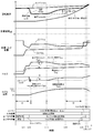
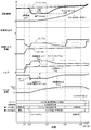
- FIG. 3 shows an example of a time chart during slip control.
- the vehicle control unit 34 is in a state where power generation by the rotating electrical machine MG is required, as in the case where the charge amount of the battery BT is low and the power consumption amount of the electric motor is large, and the vehicle is stopped. If the vehicle is in a stopped state, the engine E is rotated without being stopped even when the vehicle is stopped, and the stop engine power generation mode in which the rotating electrical machine MG generates power with the rotational driving force of the engine E is executed. It is configured. In this stop engine power generation mode, the first engagement device CL1 is controlled to be in the direct engagement state, and the second engagement device CL2 is controlled to be in the release state.
- the driving force of the engine E is transmitted to the rotating electrical machine MG and is not transmitted to the wheels W.
- the target rotational speeds of the engine E and the rotating electrical machine MG are determined based on the target power generation amount Wgo, and are set to target rotational speeds such that the temperatures of the coils of the rotating electrical machine MG and the inverter IN are not excessively increased by power generation.
- the vehicle control unit 34 is in a state where the vehicle is stopped as in the stop engine power generation mode, in which the first engagement device CL1 is controlled in the direct engagement state, and the second engagement device CL2 is in the released state.
- the slip control unit 46 starts slip control (time t11).
- the slip control unit 46 starts torque control for setting the second target torque capacity T2o of the second engagement device CL2 according to the vehicle request torque Trq, and releases the second engagement device CL2.
- a torque corresponding to the vehicle required torque Trq is transmitted to the wheel W side by the slip transmission torque of the second engagement device CL2 to rotate the vehicle speed (rotation of the output shaft O).
- (Speed) is increased (from time t11 to time t15).
- the slip control unit 46 sets the first target torque capacity T1o of the first engagement device CL1 to shift the first engagement device CL1 from the direct engagement state to the slip engagement state after the slip control is started. Perform a sweepdown that gradually decreases from the fully engaged capacity.
- the slip controller 46 determines that the first engagement device CL1 is in the slip engagement state when a rotational speed difference occurs between the rotational speed ⁇ e of the engine E and the rotational speed ⁇ m of the rotating electrical machine MG. Ending the decrease in the first target torque capacity T1o of the first engagement device CL1 and starting the engine speed control for changing the first target torque capacity T1o so that the rotational speed ⁇ e of the engine E approaches the target rotational speed ⁇ mo (Time t12).
- the complete engagement capacity is a transmission torque capacity of the engagement device that can maintain an engagement state without slipping even if the torque transmitted from the driving force source to the engagement device fluctuates.
- the complete engagement capacity is set to a transmission torque capacity that does not cause the engagement apparatus to slip even when the torque transmitted from the driving force source to the engagement apparatus becomes maximum.
- the slip control unit 46 causes the power generation rotation speed control unit 47 to start power generation rotation speed control (time t12). That is, the power generation rotational speed control is executed when both the first engagement device CL1 and the second engagement device CL2 are in the sliding engagement state and the rotating electrical machine MG is in the power generation state (time t12). To time t15).
- the power generation rotational speed control unit 47 sets the target rotational speed ⁇ mo of the rotating electrical machine MG in the power generation rotational speed control of the engine E in order to maintain the first engagement device CL1 in the sliding engagement state having a predetermined rotational speed difference. A rotational speed lower than the rotational speed ⁇ e is set.
- the power generation rotational speed control unit 47 causes the rotational speed ⁇ m of the rotating electrical machine MG to approach the target rotational speed ⁇ mo set at a rotational speed lower than the rotational speed ⁇ e of the engine E while the rotating electrical machine MG is generating power.
- the output torque Tm regenerative torque
- the power generation rotational speed control unit 47 sets a rotational speed lower than the rotational speed ⁇ e of the engine E by a predetermined value as the reference rotational speed ⁇ mob. Then, when the increase correction of the target rotational speed ⁇ mo based on the monitoring target temperature is not necessary, the power generation rotational speed control unit 47 sets the reference rotational speed ⁇ mob as the target rotational speed ⁇ mo and performs the rotational speed control (time t12). To time t13). When the correction based on the monitoring target temperature is necessary, the power generation rotation speed control unit 47 determines the target rotation speed ⁇ mo based on the monitoring target temperature and performs the power generation rotation speed control (from time t13 to time t15). Further, the power generation rotation speed control unit 47 performs power generation amount maintenance control for maintaining the power generation amount Wg of the rotating electrical machine MG at the target power generation amount Wgo during the power generation rotation speed control (from time t12 to time t15).
- the slip control unit 46 increases the rotation speed of the output shaft O, the output rotation speed calculated by multiplying the rotation speed of the output shaft O by the speed ratio of the speed change mechanism TM, and the rotation speed ⁇ m of the rotating electrical machine MG.
- the second target torque capacity T2o of the second engagement device CL2 is completely engaged. A sweep-up that gradually increases to the capacity is started (time t15).
- the slip control part 46 complete finishes the electric power generation rotational speed control of the rotary electric machine MG, and starts the torque control of the rotary electric machine MG (time t15).
- the output rotational speed is a rotational speed obtained by converting the rotational speed of the output shaft O to the rotational speed on the rotating electrical machine MG side, and the rotational speed difference between the output rotational speed and the rotational speed ⁇ m of the rotating electrical machine MG is This corresponds to a difference in rotational speed between the engaging members of the two engaging device CL2.
- the slip controller 46 further increases when the rotational speed of the output shaft O further increases and the rotational speed difference between the rotational speed ⁇ m of the rotating electrical machine MG and the rotational speed ⁇ e of the engine E becomes a predetermined value or less (time t16).
- the engine rotation speed control of the first engagement device CL1 is terminated, and the first target torque capacity of the first engagement device CL1 is completed.
- a sweep-up that gradually increases T1o to the full engagement capacity is started, and after the sweep-up is finished, a series of slip control is finished (time t17).
- the power generation rotational speed control unit 47 that executes the power generation rotational speed control during the slip control will be described in detail.
- the power generation rotation speed control unit 47 is configured so that both the first engagement device CL1 and the second engagement device CL2 are in the sliding engagement state and the rotation electrical machine MG is generating power.
- This is a functional unit that executes power generation rotational speed control for controlling the output torque Tm of the rotating electrical machine MG so that the rotational speed ⁇ m approaches the target rotational speed ⁇ mo.
- the power generation rotation speed control unit 47 monitors at least one of the temperature of the rotating electrical machine MG and the temperature of the inverter IN as the monitoring target temperature, and determines the target rotation speed ⁇ mo based on the monitoring target temperature.
- the power generation amount maintenance control for maintaining the power generation amount Wg of the rotating electrical machine MG during the power generation rotation speed control at the target power generation amount Wgo is executed.
- the power generation rotational speed control unit 47 slips both the first engagement device CL1 and the second engagement device CL2 by the slip control described above during power generation of the rotating electrical machine MG by the driving force of the engine E. It is configured to perform power generation rotation speed control while controlling to the engaged state.
- the electric power generation amount Wg of the rotating electrical machine MG is proportional to the value obtained by multiplying the magnitude (absolute value) of the regenerative torque Tg and the rotational speed ⁇ m of the rotating electrical machine MG, as shown by the equation (1).
- the coil temperature Tc is a temperature in which the heat generation amount Wc due to the current Ic applied to the coil and the heat dissipation amount and cooling amount coming out of the coil are balanced, and as the heat generation amount Wc due to the current Ic increases, It becomes a steady characteristic in which the temperature Tc increases. Further, the heat generation amount Wc due to the current Ic is inversely proportional to the square of the rotational speed ⁇ m of the rotating electrical machine MG from the above formulas (2), (3), and (4) under the condition that the power generation amount Wg is constant. Change. Therefore, as shown in FIG. 5, the coil temperature Tc has a steady characteristic that increases as the rotational speed ⁇ m of the rotating electrical machine MG decreases under the condition that the power generation amount Wg is constant.
- the coil temperature Tc changes with a response delay such as a first-order lag with respect to the change in the heat generation amount Wc of the coil due to the heat capacity of the coil. For this reason, as shown in FIG. 5, after the rotational speed ⁇ m of the rotating electrical machine MG is lowered from the operating point A to the operating point B by the slip control, the coil temperature Tc has a response delay from the operating point B to the operating point E. It rises. Therefore, after the rotational speed ⁇ m of the rotating electrical machine MG is reduced by the slip control, a time lag, that is, a margin time occurs until the coil temperature Tc exceeds the allowable upper limit temperature Tmxc.
- the rotational speed ⁇ m of the rotating electrical machine MG is maintained at the reference rotational speed ⁇ mob set to a relatively low value by the slip control as much as possible during the margin time due to the response delay of the coil temperature Tc change,
- the advantage of slip control such as heat generation reduction of the second engagement device CL2 is not impaired. That is, as will be described later, the power generation rotational speed control unit 47 is configured to increase the rotational speed ⁇ m of the rotating electrical machine MG according to the coil temperature Tc that rises with a response delay due to the heat capacity of the coil.
- the temperature Tin of the inverter IN is a temperature in which the amount of heat generated by the inverter IN due to the current Ic, the amount of heat released from the inverter IN, and the amount of cooling are balanced, and as the amount of heat generated by the current Ic increases, It becomes a steady characteristic in which the temperature Tin increases.
- the inverter temperature Tin has a steady characteristic that increases as the rotational speed ⁇ m of the rotating electrical machine MG decreases under the condition that the power generation amount Wg is constant. Therefore, it is necessary to increase the rotational speed ⁇ m of the rotating electrical machine MG from the reference rotational speed ⁇ mob set by the slip control so that the inverter temperature Tin does not exceed the allowable upper limit temperature Tmxi of the inverter IN.
- the temperature change of the inverter IN has a response delay due to the heat capacity of the inverter IN and the like, similar to the above-described coil. Therefore, during the margin time due to the response delay of the inverter temperature Tin change, the rotational speed ⁇ m of the rotating electrical machine MG is maintained as much as possible at the rotational speed (reference rotational speed ⁇ mob) set to a relatively low value by the slip control.
- the advantage of slip control such as reduction of heat generation of the engaging device CL2 is not impaired. That is, the power generation rotational speed control unit 47 is configured to increase the rotational speed ⁇ m of the rotating electrical machine MG in accordance with the inverter temperature Tin, as will be described later.
- the power generation rotation speed control unit 47 monitors at least one of the coil temperature Tc as the temperature of the rotating electrical machine MG and the temperature Tin of the inverter IN as the monitoring target temperature, and based on the monitoring target temperature, the target rotation speed It is configured to determine ⁇ mo.
- the power generation rotation speed control unit 47 performs the target rotation so that the value increases as the coil temperature Tc increases.
- the speed ⁇ mo is determined.
- the control temperature regions are each set to a temperature region equal to or higher than the control start temperature Tsc that is lower than the allowable upper limit temperature Tmxc by a predetermined temperature.
- the power generation rotational speed control unit 47 is defined according to the target power generation amount Wgo when the coil temperature Tc as the monitoring target temperature becomes a predetermined allowable upper limit temperature Tmxc.
- the target rotational speed ⁇ mo is increased to the temperature equilibrium rotational speed that is the rotational speed and the rotational speed at which the coil temperature Tc does not exceed the allowable upper limit temperature Tmxc regardless of the operation time of the rotating electrical machine MG (that is, constantly). It is configured as follows. As shown in the example of FIG. 7, the temperature equilibrium rotation speed has a characteristic that increases as the target power generation amount Wgo increases. The temperature equilibrium rotation speed is as shown in FIG. 7 for each coil temperature Tc.
- the power generation rotational speed control unit 47 may be configured to increase the target rotational speed ⁇ mo to a rotational speed higher than the temperature equilibrium rotational speed when the coil temperature Tc reaches the allowable upper limit temperature Tmxc. If comprised in this way, it can prevent more reliably that coil temperature Tc exceeds permissible upper limit temperature Tmxc.
- the temperature equilibrium rotational speed is a predetermined temperature equilibrium rotational speed corresponding to the maximum target power generation amount Wgo that can be set during the slip control, or even if fluctuation or disturbance occurs, the coil temperature Tc does not exceed the allowable upper limit temperature Tmxc.
- Such a predetermined rotation speed may be set to a fixed value regardless of the change in the target power generation amount Wgo. With this configuration, it is possible to reliably prevent the coil temperature Tc from exceeding the allowable upper limit temperature Tmxc with a simple configuration.
- the power generation rotational speed control unit 47 sets the target rotational speed ⁇ mo to the reference rotational speed determined by the slip control as the coil temperature Tc rises from the control start temperature Tsc to the allowable upper limit temperature Tmxc. It is configured to gradually increase from ⁇ mob to the temperature equilibrium rotational speed. With this configuration, as the coil temperature Tc approaches the allowable upper limit temperature Tmxc from the control start temperature Tsc, the rotational speed ⁇ m of the rotating electrical machine MG is increased and the magnitude of the regenerative torque is decreased. The amount of heat generated by the coil can be reduced.
- the target rotational speed ⁇ mo is configured to increase at a constant gradient as the coil temperature Tc increases, but may be configured to increase at an arbitrary gradient. . Further, the target rotational speed ⁇ mo may be configured to increase stepwise from the reference rotational speed ⁇ mob to the temperature equilibrium rotational speed at a coil temperature Tc that is equal to or lower than the allowable upper limit temperature Tmxc.
- the power generation rotational speed control unit 47 is configured to gradually increase the target rotational speed ⁇ mo from the temperature equilibrium rotational speed as the coil temperature Tc increases from the allowable upper limit temperature Tmxc. Yes.
- the target rotational speed ⁇ mo can be further increased from the temperature equilibrium rotational speed, and the coil temperature Tc becomes the allowable upper limit temperature Tmxc. Can be greatly suppressed.
- the power generation rotational speed control unit 47 gradually increases the target rotational speed ⁇ mo from the temperature equilibrium rotational speed until the coil temperature Tc becomes equal to or lower than the allowable upper limit temperature Tmxc. You may comprise.
- the power generation rotational speed control unit 47 sets the reference rotational speed ⁇ mob to the target rotational speed. The speed ⁇ mo is determined.
- the reference rotation speed ⁇ mob may be configured to be set to a lower limit rotation speed that can ensure the target power generation amount Wgo.
- the lower limit rotation speed is set to a rotation speed such that the power generation amount Wg of the rotary electric machine MG becomes the target power generation amount Wgo when the maximum amount of regenerative torque that can be output to the rotary electric machine MG is output.
- ⁇ m can be reduced to a lower limit that can ensure the target power generation amount Wgo, and the rotational speed difference between the engagement members of the second engagement device CL2 can be reduced. Therefore, the heat generation in the sliding engagement state of CL2 of the second engagement device can be reduced. Note that the amount of heat generated by the engaging device in the sliding engagement state is proportional to a value obtained by multiplying the rotational speed difference between the engaging members and the slip transmission torque.
- the power generation rotational speed control unit 47 is configured to determine the target rotational speed ⁇ mo based on the inverter temperature Tin by the same determination method as that for the coil temperature Tc described so far.
- FIGS. 6 and 7 when the monitoring target temperature is the coil temperature Tc are FIGS. 8 and 9, respectively, when the monitoring target temperature is the inverter temperature Tin.
- the allowable upper limit temperature Tmxc and the control start temperature Tsc are the allowable upper limit temperature Tmxi and the control start temperature Tsi as shown in FIG. 8 when the monitored temperature is the inverter temperature Tin. It becomes.
- set values such as the control temperature region, the allowable upper limit temperature Tmxi, the control start temperature Tsi, and the temperature equilibrium rotational speed are set according to the heat generation characteristics of the inverter IN.
- the power generation rotational speed control unit 47 determines the first target rotational speed ⁇ mo1 based on the coil temperature Tc as the temperature of the rotating electrical machine MG and the second target rotational speed ⁇ mo2 based on the temperature of the inverter IN, and the first target rotational speed The target rotational speed ⁇ mo is determined based on the higher one of ⁇ mo1 and the second target rotational speed ⁇ mo2.
- the first target rotation speed determination unit 50 provided in the power generation rotation speed control unit 47 determines the first target rotation speed ⁇ mo1 based on the coil temperature Tc as described above, and The two target rotation speed determination unit 51 is configured to determine the second target rotation speed ⁇ mo2 based on the inverter temperature Tin. Then, the maximum value collector 52 is configured to set the higher one of the first target rotation speed ⁇ mo1 and the second target rotation speed ⁇ mo2 as the temporary target rotation speed ⁇ mot.
- the reference rotation speed determination unit 58 is configured to determine the reference rotation speed ⁇ mob based on the target power generation amount Wgo as described above. Alternatively, the reference rotational speed ⁇ mob determined by the slip control unit 46 may be used.
- the upper limit limiter 53 is configured to set a value obtained by limiting the temporary target rotational speed ⁇ mot with the rotational speed ⁇ e of the engine E as the target rotational speed ⁇ mo.
- the upper limit limiter 53 is configured to set the smaller value of the temporary target rotational speed ⁇ mot and the rotational speed ⁇ e of the engine E as the target rotational speed ⁇ mo. With this configuration, the rotational speed ⁇ m of the rotating electrical machine MG can be maintained below the rotational speed ⁇ e of the engine E. Therefore, the state in which the slip transmission torque of the first engagement device CL1 is transmitted from the engine E side to the rotating electrical machine MG side can be maintained, and the rotating electrical machine MG can be continuously generated by the driving force of the engine E. .
- the power generation rotational speed control unit 47 limits the upper limit of the target rotational speed ⁇ mo determined based on the monitoring target temperature to the rotational speed ⁇ e of the engine E, so that the target rotational speed ⁇ mo is the rotational speed of the engine E.
- the first engagement device CL1 is configured to shift from the sliding engagement state to the direct coupling state. More specifically, when the rotational speed difference between the rotational speed ⁇ m of the rotating electrical machine MG and the rotational speed ⁇ e of the engine E becomes equal to or less than a predetermined value, the power generation rotational speed control unit 47 performs the first rotation of the first engagement device CL1.
- the first engagement device CL1 is configured to shift from the sliding engagement state to the direct engagement state by performing a sweep-up that gradually increases the one target torque capacity T1o to the complete engagement capacity. Thereby, the driving force of the engine E is directly transmitted to the rotating electrical machine MG, and the rotating electrical machine MG can be stably generated by the driving force of the engine E.
- the power generation rotational speed control unit 47 may be configured to set the temporary target rotational speed ⁇ mot as the target rotational speed ⁇ mo as it is without limiting the temporary target rotational speed ⁇ mot with the rotational speed ⁇ e of the engine E. . Also in this case, the power generation rotational speed control unit 47 detects the first engagement device CL1 first when the rotational speed difference between the rotational speed ⁇ m of the rotating electrical machine MG and the rotational speed ⁇ e of the engine E becomes a predetermined value or less. Sweep up is performed to gradually increase the target torque capacity T1o to the full engagement capacity, and the first engagement device CL1 is shifted from the sliding engagement state to the direct engagement state.
- the engine can be controlled by controlling the first engagement device CL1 to the direct engagement state. While ensuring that the driving force of E is transmitted to the rotating electrical machine MG, the rotational speed ⁇ m of the rotating electrical machine MG can be increased to suppress overheating of both the rotating electrical machine MG and the inverter IN.
- the rotational speed ⁇ e of the engine E is set to the target rotational speed ⁇ mo by the rotational speed control of the rotating electrical machine MG together with the rotational speed ⁇ m of the rotating electrical machine MG. Be controlled.
- the power generation rotational speed control unit 47 is configured to perform rotational speed control of the rotating electrical machine MG that changes the rotating electrical machine required torque Tmo so that the rotational speed ⁇ m of the rotating electrical machine MG approaches the target rotational speed ⁇ mo.
- a rotation feedback controller 54 is provided.
- the power generation rotation speed control unit 47 performs power generation amount maintenance control for maintaining the power generation amount Wg of the rotating electrical machine MG during the power generation rotation speed control at the target power generation amount Wgo. Is configured to do.
- the power generation rotation speed control unit 47 determines a target regenerative torque Tgo that is a target torque to be output to the rotating electrical machine MG based on the target rotation speed ⁇ mo and the target power generation amount Wgo in the power generation amount maintenance control. And one or more of the transmission torque of the first engagement device CL1, the transmission torque of the second engagement device CL2, and the output torque Te of the engine E are controlled based on the target regeneration torque Tgo. Has been.
- the rotating electrical machine required torque Tmo which is the output torque Tm of the rotating electrical machine MG, is automatically determined by the rotational speed control of the rotating electrical machine MG, and therefore rotates the target regenerative torque Tgo required to maintain the target power generation amount Wgo. It cannot be directly set to the electric machine required torque Tmo. Therefore, the torque (external acting torque) acting on the inertial system of the rotating electrical machine MG from the outside, that is, the transmission torque of the first engagement device CL1, the transmission torque of the second engagement device CL2, and the output torque Te of the engine E. By changing any one or more of them, control is performed so that the required rotating electrical machine torque Tmo indirectly approaches the target regenerative torque Tgo.
- the externally acting torque is used to maintain the rotational speed ⁇ m of the rotating electrical machine MG at the target rotational speed ⁇ mo against the increase or decrease of the externally acting torque.
- the required rotating electrical machine torque Tmo is automatically increased / decreased by the rotational speed control.
- one or more of the transmission torque of the first engagement device CL1, the transmission torque of the second engagement device CL2, and the output torque Te of the engine E based on the target regeneration torque Tgo By controlling the torque, the torque acting from the outside on the inertial system of the rotating electrical machine MG can be changed by the increase / decrease of the target regenerative torque Tgo, and the rotating electrical machine required torque Tmo is changed by the increase / decrease of the target regenerative torque Tgo. It can be changed automatically by rotation speed control.
- the target regenerative torque determining unit 55 provided in the power generation rotational speed control unit 47 uses the power generation characteristics as shown in Equation (1) and FIG. Based on ⁇ mo and the target power generation amount Wgo, a target regenerative torque Tgo to be output to the rotating electrical machine MG is determined.
- the target regenerative torque Tgo corresponds to the absolute value of the negative regenerative torque. According to this configuration, according to the power generation characteristics as shown in FIG.
- the target regenerative torque Tgo is increased (from the operating point A to the operating point B
- the target regenerative torque Tgo is decreased (corresponding to a change from the operating point C to the operating point D).
- the power generation rotational speed control unit 47 is configured to control the output torque Te of the engine E based on the target regenerative torque Tgo. Specifically, as shown in FIG. 11, the power generation rotational speed control unit 47 is configured to perform torque control in which a value obtained by adding the target regenerative torque Tgo to the vehicle required torque Trq is set as the engine required torque Teo. Yes. Then, the power generation rotational speed control unit 47 changes the first target torque capacity T1o so that the rotational speed ⁇ e of the engine E approaches the target rotational speed ⁇ eo of the engine E as control of the transmission torque of the first engagement device CL1. The engine rotation speed control is performed, and a rotation feedback controller 56 is provided.
- the output torque Te of the engine E changes by the increase / decrease amount of the target regenerative torque Tgo.
- the rotation speed ⁇ e of the engine E tends to change, but the transmission torque of the first engagement device CL1 is automatically increased or decreased by the engine rotation speed control of the first engagement device CL1.
- the rotational speed ⁇ e of the engine E is maintained at the target rotational speed ⁇ eo of the engine E.
- the transmission torque of the first engagement device CL1 is automatically increased by the increase of the output torque Te of the engine E by the engine rotation speed control.
- the transmission torque of the first engagement device CL1 increases by the increase of the target regeneration torque Tgo.
- the torque acting on the inertial system of the engine E decreases by the increase in the transmission torque, and the rotational speed ⁇ e of the engine E is maintained at the target rotational speed ⁇ eo.
- the transmission torque of the first engagement device CL1 is a torque that acts on the inertial system of the rotating electrical machine MG from the outside.
- the output torque Tm of the rotating electrical machine MG is increased by the increase in the transmission torque of the first engagement device CL1 by the rotational speed control of the rotating electrical machine MG. It will decrease automatically. Therefore, the output torque Tm of the rotating electrical machine MG decreases by the increase of the target regenerative torque Tgo.
- the transmission torque of the first engagement device CL1 is increased by this increase by the engine speed control by the first engagement device CL1.
- the output torque Tm is automatically increased, and the output torque Tm of the rotating electrical machine MG is automatically reduced by the increased amount by the rotational speed control of the rotating electrical machine. Therefore, according to the above configuration, the output torque Tm of the rotating electrical machine MG is indirectly decreased by the increase of the target regenerative torque Tgo by increasing the output torque Te of the engine E by the increase of the target regenerative torque Tgo.
- the magnitude of the regenerative torque of the rotating electrical machine MG can be increased.
- the power generation rotational speed control unit 47 is configured to perform torque control for setting the vehicle required torque Trq as the second target torque capacity T2o as control of the transmission torque of the second engagement device CL2, and a setting device 57. For this reason, the torque that acts on the inertial system of the rotating electrical machine MG from the second engagement device CL2 side does not change regardless of the increase or decrease of the target regenerative torque Tgo.
- the target regenerative torque Tgo is set to a relatively small value, so the coil temperature Tc is the allowable upper limit temperature.
- the temperature T1 is maintained lower than Tmxc and the control start temperature Tsc.
- the target rotational speeds of the engine E and the rotating electrical machine MG before the start of the slip control are maintained at the coil temperature Tc lower than the allowable upper limit temperature Tmxc based on the target power generation amount Wgo. This is because such a rotational speed is set.
- the target regenerative torque Tgo is maintained in order to maintain the power generation amount Wg of the rotating electrical machine MG at the target power generation amount Wgo. 4 is increased in inverse proportion to the decrease in the target rotational speed ⁇ mo.
- the engine required torque Teo is increased by the increase of the target regenerative torque Tgo.
- the first target torque capacity T1o is automatically increased by the increased amount by the engine speed control by the first engagement device CL1
- the rotating electrical machine required torque Tmo is automatically increased by the increased amount by the rotating electrical machine rotational speed.
- the rotating electrical machine required torque Tmo is indirectly decreased by the increase of the target regenerative torque Tgo, and the power generation amount Wg of the rotary electrical machine MG is maintained at the target power generation amount Wgo.
- the heat generation amount Wc of the coil is increased.
- the coil temperature Tc rises with a response delay due to the heat capacity of the coil and the like with respect to the increase in the heat generation amount Wc of the coil (from time t12 to time t13). Therefore, there is a time lag until the coil temperature Tc reaches the control start temperature Tsc after the target rotational speed ⁇ mo is reduced (period from time t12 to time t13).
- the rotational speed ⁇ m of the rotating electrical machine MG can be maintained at the reference rotational speed ⁇ mob set to a relatively low value, and the rotational speed difference between the engaging members of the second engagement device CL2 is maintained. And the amount of heat generated by the second engagement device CL2 can be reduced.
- the target rotational speed ⁇ mo in the power generation rotational speed control is increased from the reference rotational speed ⁇ mob as the coil temperature Tc increases.
- the power generation rotation speed control unit 47 changes the target rotation speed ⁇ mo from the reference rotation speed ⁇ mob to the temperature balanced rotation as the coil temperature Tc approaches the allowable upper limit temperature Tmxc from the control start temperature Tsc. It is configured to gradually increase to the speed. For this reason, as shown in FIG.
- the target rotational speed ⁇ mo can be reduced to the maximum when the coil temperature Tc is in the range of the control start temperature Tsc or less.
- the amount of heat generated by the second engagement device CL2 can be reduced.
- Example 2 Next, another example of the behavior of the power generation rotational speed control will be described with reference to the example of FIG.
- the example shown in FIG. 12 is an example in which the target rotational speed ⁇ mo is increased to the rotational speed ⁇ e of the engine E by the power generation rotational speed control, unlike the case of FIG.
- the refrigerant that cools the coil is shared with the refrigerant that cools the second engagement device CL2, and the second engagement device CL2 is brought into a sliding engagement state during the slip control and generates heat.
- the temperature of the refrigerant that cools the coil rises more than before the slip control.
- Other conditions are the same as in FIG.
- the power generation rotation speed control unit 47 also takes into consideration the increase in the coil temperature Tc due to the heat generated by the second engagement device CL2, so that the coil temperature Tc does not exceed the allowable upper limit temperature Tmxc.
- the target rotational speed ⁇ mo is determined based on the coil temperature Tc.
- the target rotational speed ⁇ mo is increased with a larger slope than in the example shown in FIG.
- the rotational speed ⁇ e of the engine E is increased.
- the power generation rotational speed control unit 47 is configured to set the upper limit of the target rotational speed ⁇ mo with the rotational speed ⁇ e of the engine E (time t24 to t26). For this reason, the target rotational speed ⁇ mo is limited to the rotational speed ⁇ e of the engine E or less. Therefore, the state where the slip transmission torque of the first engagement device CL1 is transmitted from the engine E side to the rotating electrical machine MG side can be maintained, and the rotating electrical machine MG can generate electric power by the driving force of the engine E.
- the power generation rotational speed control unit 47 causes the first engagement device CL1 to be in the direct engagement state when the rotational speed difference between the rotational speed ⁇ m of the rotating electrical machine MG and the rotational speed ⁇ e of the engine E becomes a predetermined value or less. It is configured to be migrated to. For this reason, when the rotational speed difference becomes equal to or less than a predetermined value, the first target torque capacity T1o is swept up to the full engagement capacity, and is shifted to the direct engagement state (time t24). Therefore, the driving force of the engine E is directly transmitted to the rotating electrical machine MG, and the rotating electrical machine MG can be stably generated by the driving force of the engine E.
- the target rotational speed ⁇ mo may be determined based on the coil temperature Tc by executing power generation rotational speed control. . If comprised in this way, overheating of a coil can be suppressed more reliably.
- the vehicle drive device 1 further includes an engagement device in the power transmission path 2 between the rotating electrical machine MG and the speed change mechanism TM, and the engagement device is controlled to be in the slip engagement state during the slip control. It may be a two-engagement device CL2.
- the vehicle drive apparatus 1 further includes a torque converter in the power transmission path 2 between the rotating electrical machine MG and the speed change mechanism TM, and a lockup clutch that directly connects the input and output members of the torque converter is It may be a two-engagement device CL2.
- the second engagement device CL2 is controlled to the slip engagement state during the slip control.
- the vehicle drive device 1 may be configured not to include the speed change mechanism TM.
- the speed change mechanism TM is a stepped automatic transmission
- the embodiment of the present invention is not limited to this. That is, the speed change mechanism TM may be configured to be a speed change device other than the stepped automatic speed change device such as a continuously variable automatic speed change device capable of continuously changing the speed ratio.
- the engagement device provided in the speed change mechanism TM is the second engagement device CL2 that is controlled to the slip engagement state during the slip control, or the engagement device provided separately from the speed change mechanism TM. May be the second engagement device CL2.
- the control device 30 includes a plurality of control units 32 to 34, and a case where the plurality of control units 32 to 34 share a plurality of functional units 41 to 47 will be described as an example. did.
- the embodiment of the present invention is not limited to this. That is, the control device 30 may be provided as a control device in which the plurality of control units 32 to 34 described above are integrated or separated in any combination, and the assignment of the plurality of functional units 41 to 47 is also arbitrarily set. Can do.
- the power generation rotational speed control may be in any state as long as both the first engagement device CL1 and the second engagement device CL2 are in the sliding engagement state and the rotating electrical machine MG is in the power generation state.
- the power generation rotational speed control may be configured to be executed during extremely low speed traveling or during deceleration of the vehicle.
- the power generation rotational speed control unit 47 exemplifies a case where both the coil temperature Tc as the temperature of the rotating electrical machine MG and the temperature of the inverter IN are monitored temperatures.
- the embodiment of the present invention is not limited to this. That is, the power generation rotational speed control unit 47 may set at least one of the temperature of the rotating electrical machine MG and the temperature of the inverter IN as the monitoring target temperature, for example, only the temperature of the rotating electrical machine MG is set as the monitoring target temperature. Only the temperature of IN may be configured as the monitoring target temperature.
- the power generation rotation speed control unit 47 when the monitored temperature is within a predetermined control temperature region, the power generation rotation speed control unit 47 causes the target rotation to increase as the monitored temperature increases.
- the case where the speed ⁇ mo is determined has been described as an example.
- the embodiment of the present invention is not limited to this. That is, as long as the target rotational speed ⁇ mo is determined based on the monitoring target temperature, the determination method may be arbitrary.
- the power generation rotational speed control unit 47 sets the monitoring target temperature to the allowable upper limit temperature Tmxc or less.
- the target rotational speed ⁇ mo may be changed by feedback control so that the target temperature approaches the target temperature or the monitored temperature becomes equal to or lower than the target temperature.
- control temperature range is set to a temperature range equal to or higher than the control start temperature Tsc that is lower than the allowable upper limit temperature Tmxc by a predetermined temperature.
- the embodiment of the present invention is not limited to this. That is, the control temperature region may be set to any temperature range within a predetermined temperature range including the allowable upper limit temperature Tmxc, and when the control temperature region is within the control temperature region, the control temperature region increases as the monitoring target temperature increases.
- the target rotational speed ⁇ mo may be determined so that
- the power generation rotational speed control unit 47 is configured to determine the engine required torque Teo based on the target regenerative torque Tgo.
- the embodiment of the present invention is not limited to this. That is, the power generation rotational speed control unit 47 is one of the transmission torque of the first engagement device CL1, the transmission torque of the second engagement device CL2, and the output torque Te of the engine E based on the target regeneration torque Tgo. What is necessary is just to be comprised so that the above may be controlled, for example, you may be comprised so that 1st target torque capacity
- the power generation rotational speed control unit 47 performs torque control for setting, as the first target torque capacity T1o, a value obtained by adding the target regeneration torque Tgo to the vehicle request torque Trq as control of the transmission torque of the first engagement device CL1.
- engine rotational speed control is performed in which the engine required torque Teo is changed so that the rotational speed ⁇ e of the engine E approaches the target rotational speed ⁇ eo of the engine E. May be.
- the power generation rotational speed control unit 47 corrects the second target torque capacity T2o determined based on the vehicle required torque Trq based on the target regenerative torque Tgo, and so on, based on the target regenerative torque Tgo.
- the capacity T2o may be determined.
- the present invention provides a power transmission path that connects an input member that is drivingly connected to an internal combustion engine and an output member that is drivingly connected to a wheel, from the input member side to the first engagement device, the rotating electrical machine, and the second engagement. It can utilize suitably for the control apparatus which makes the vehicle drive device provided in order of the apparatus the control object.
Landscapes
- Engineering & Computer Science (AREA)
- Transportation (AREA)
- Mechanical Engineering (AREA)
- Chemical & Material Sciences (AREA)
- Combustion & Propulsion (AREA)
- Power Engineering (AREA)
- Automation & Control Theory (AREA)
- Life Sciences & Earth Sciences (AREA)
- Sustainable Development (AREA)
- Sustainable Energy (AREA)
- Electric Propulsion And Braking For Vehicles (AREA)
- Hybrid Electric Vehicles (AREA)
Abstract
Description
また、本願において、「駆動連結」とは、2つの回転要素が駆動力を伝達可能に連結された状態を指し、当該2つの回転要素が一体的に回転するように連結された状態、或いは当該2つの回転要素が一又は二以上の伝動部材を介して駆動力を伝達可能に連結された状態を含む概念として用いている。このような伝動部材としては、回転を同速で又は変速して伝達する各種の部材が含まれ、例えば、軸、歯車機構、ベルト、チェーン等が含まれる。また、このような伝動部材として、回転及び駆動力を選択的に伝達する係合装置、例えば摩擦係合装置や噛み合い式係合装置等が含まれていてもよい。
一方、回生トルクの大きさの増加により、回転電機の温度及びインバータの温度が上昇する。そこで上記の特徴構成のように、回転電機の温度及びインバータの温度の少なくとも一方を監視対象温度として監視し、当該監視対象温度に基づいて目標回転速度を決定することで、監視対象温度が上昇しすぎないように、回転電機の目標回転速度を増加させて、発電量維持制御により回生トルクの大きさを減少させることができる。よって、必要とされる発電量を確保しながら、監視対象温度の上昇を抑制することができ、回転電機又はインバータ(若しくはその両方;以下同様)の過熱を抑制することができる。
なお、エンジン出力軸Eoが、本発明における「入力部材」であり、出力軸Oが、本発明における「出力部材」である。
そして、発電回転速度制御部47は、発電回転速度制御において、回転電機MGの温度としてのコイル温度Tc及びインバータINの温度Tinの少なくとも一方を監視対象温度として監視し、当該監視対象温度に基づいて目標回転速度ωmoを決定すると共に、発電回転速度制御中の回転電機MGの発電量Wgを目標発電量Wgoに維持する発電量維持制御を実行する点に特徴を有している。
以下、本実施形態に係る車両用駆動装置1及び制御装置30について、詳細に説明する。
まず、本実施形態に係るハイブリッド車両の車両用駆動装置1の構成について説明する。図1に示すように、ハイブリッド車両は、車両の駆動力源としてエンジンE及び回転電機MGを備え、これらのエンジンEと回転電機MGとが直列に駆動連結されるパラレル方式のハイブリッド車両となっている。ハイブリッド車両は、変速機構TMを備えており、当該変速機構TMにより、中間軸Mに伝達されたエンジンE及び回転電機MGの回転速度を変速すると共にトルクを変換して出力軸Oに伝達する。
車両用駆動装置1の油圧制御系は、機械式や電動式の油圧ポンプから供給される作動油の油圧を所定圧に調整するための油圧制御装置PCを備えている。ここでは詳しい説明を省略するが、油圧制御装置PCは、油圧調整用のリニアソレノイド弁からの信号圧に基づき一又は二以上の調整弁の開度を調整することにより、当該調整弁からドレインする作動油の量を調整して作動油の油圧を一又は二以上の所定圧に調整する。所定圧に調整された作動油は、それぞれ必要とされるレベルの油圧で、変速機構TM、並びに第一係合装置CL1や第二係合装置CL2の各摩擦係合要素等に供給される。
次に、車両用駆動装置1の制御を行う制御装置30及びエンジン制御装置31の構成について、図2を参照して説明する。
制御装置30の制御ユニット32~34及びエンジン制御装置31は、CPU等の演算処理装置を中核部材として備えるとともに、当該演算処理装置からデータを読み出し及び書き込みが可能に構成されたRAM(ランダム・アクセス・メモリ)や、演算処理装置からデータを読み出し可能に構成されたROM(リード・オンリ・メモリ)等の記憶装置等を有して構成されている。そして、制御装置のROM等に記憶されたソフトウェア(プログラム)又は別途設けられた演算回路等のハードウェア、或いはそれらの両方により、制御装置30の各機能部41~47などが構成されている。また、制御装置30の制御ユニット32~34及びエンジン制御装置31は、互いに通信を行うように構成されており、センサの検出情報及び制御パラメータ等の各種情報を共有するとともに協調制御を行い、各機能部41~47の機能が実現される。
エンジン回転速度センサSe1は、エンジン出力軸Eo(エンジンE)の回転速度を検出するためのセンサである。エンジン制御装置31は、エンジン回転速度センサSe1の入力信号に基づいてエンジンEの回転速度ωeを検出する。
入力回転速度センサSe2は、入力軸I及び中間軸Mの回転速度を検出するためのセンサである。入力軸I及び中間軸Mには回転電機MGのロータが一体的に駆動連結されているので、制御装置30は、入力回転速度センサSe2の入力信号に基づいて回転電機MGの回転速度ωm、並びに入力軸I及び中間軸Mの回転速度を検出する。
出力回転速度センサSe3は、出力軸Oの回転速度を検出するためのセンサである。制御装置30は、出力回転速度センサSe3の入力信号に基づいて出力軸Oの回転速度を検出する。また、出力軸Oの回転速度は車速に比例するため、制御装置30は、出力回転速度センサSe3の入力信号に基づいて車速を算出する。
バッテリ充電状態検出センサSe5は、バッテリBTの充電状態を検出するためのセンサである。本実施形態では、バッテリ充電状態検出センサSe5は、バッテリ電圧を検出するための電圧センサ、バッテリ電流を検出するための電流センサ、及びバッテリ温度を検出するための温度センサなどから構成されたセンサである。制御装置30は、バッテリ充電状態検出センサSe5の入力信号に基づいて、バッテリBTの充電量を推定する。
エンジン制御装置31は、エンジンEの動作制御を行うエンジン制御部41を備えている。本実施形態では、エンジン制御部41は、車両制御ユニット34からエンジン要求トルクが指令されている場合は、車両制御ユニット34から指令されたエンジン要求トルクを出力トルク指令値に設定し、エンジンEが出力トルク指令値のトルクを出力するように制御するトルク制御を行う。また、エンジン制御装置31は、エンジン始動要求があった場合は、エンジンEの燃焼開始が指令されたと判定して、エンジンEへの燃料供給及び点火を開始するなどして、エンジンEの燃焼を開始する制御を行う。
動力伝達制御ユニット33は、変速機構TMの制御を行う変速機構制御部43と、第一係合装置CL1の制御を行う第一係合装置制御部44と、スリップ制御中に第二係合装置CL2の制御を行う第二係合装置制御部45と、を備えている。
変速機構制御部43は、変速機構TMに変速段を形成する制御を行う。変速機構制御部43は、車速、アクセル開度、及びシフト位置などのセンサ検出情報に基づいて変速機構TMにおける目標変速段を決定する。そして、変速機構制御部43は、油圧制御装置PCを介して変速機構TMに備えられた複数の係合装置に供給される油圧を制御することにより、各係合装置を係合又は解放して目標とされた変速段を変速機構TMに形成させる。具体的には、変速機構制御部43は、油圧制御装置PCに各係合装置の目標油圧(指令圧)を指令し、油圧制御装置PCは、指令された目標油圧(指令圧)の油圧を各係合装置に供給する。
第一係合装置制御部44は、第一係合装置CL1の係合状態を制御する。本実施形態では、第一係合装置制御部44は、第一係合装置CL1の伝達トルク容量が、車両制御ユニット34から指令された第一目標トルク容量T1oに一致するように、油圧制御装置PCを介して第一係合装置CL1に供給される油圧を制御する。具体的には、第一係合装置制御部44は、第一目標トルク容量T1oに基づき設定した目標油圧(指令圧)を、油圧制御装置PCに指令し、油圧制御装置PCは、指令された目標油圧(指令圧)の油圧を第一係合装置CL1に供給する。
第二係合装置制御部45は、スリップ制御中に第二係合装置CL2の係合状態を制御する。本実施形態では、第二係合装置CL2は、変速機構TMの変速段を形成している複数又は単数の係合装置の一つとされる。
本実施形態では、第二係合装置制御部45は、第二係合装置CL2の伝達トルク容量が、車両制御ユニット34から指令された第二目標トルク容量T2oに一致するように、油圧制御装置PCを介して第二係合装置CL2に供給される油圧を制御する。具体的には、第二係合装置制御部45は、第二目標トルク容量T2oに基づき設定した目標油圧(指令圧)を、油圧制御装置PCに指令し、油圧制御装置PCは、指令された目標油圧(指令圧)の油圧を第二係合装置CL2に供給する。
回転電機制御ユニット32は、回転電機MGの動作制御を行う回転電機制御部42を備えている。本実施形態では、回転電機制御部42は、車両制御ユニット34から指令された回転電機要求トルクTmoを出力トルク指令値に設定し、回転電機MGが出力トルク指令値のトルクを出力するように制御するトルク制御を行う。具体的には、回転電機制御部42は、インバータINが備える複数のスイッチング素子をオンオフ制御することにより、回転電機MGの出力トルクTmを制御する。
車両制御ユニット34は、エンジンE、回転電機MG、変速機構TM、第一係合装置CL1、及び第二係合装置CL2等に対して行われる各種トルク制御、及び各係合装置の係合制御等を車両全体として統合する制御を行う機能部を備えている。
本実施形態では、車両制御ユニット34は、回転電機MGの発電中に第一係合装置CL1及び第二係合装置CL2の双方を滑り係合状態に制御するスリップ制御を行うスリップ制御部46、及び発電回転速度制御を行う発電回転速度制御部47を備えている。
以下、スリップ制御部46及び発電回転速度制御部47について詳細に説明する。
本実施形態では、後述する発電回転速度制御部47の処理はスリップ制御中に実行されるため、まず、発電回転速度制御部47の処理の前提となるスリップ制御部46によるスリップ制御について説明する。
本実施形態では、スリップ制御部46は、エンジンEの駆動力による回転電機MGの発電中に、第一係合装置CL1及び第二係合装置CL2の双方を滑り係合状態に制御することにより、エンジンEの回転駆動を維持したままで、エンジンEの駆動力を車輪Wにも伝達して車両を駆動することができると共に、係合装置で生じる摩擦熱を各係合装置CL1、CL2に分散させて各係合装置CL1、CL2の過熱を抑制することができる。すなわち、スリップ制御部46は、第二係合装置CL2を滑り係合状態に制御することにより、第二係合装置CL2のスリップ伝達トルクを駆動力源から車輪Wに伝達して車両を駆動することができる。また、スリップ制御部46は、第一係合装置CL1を滑り係合状態に制御することより、エンジンEの回転速度ωeを維持したままで回転電機MGの回転速度ωmを低減することができる。これにより、第二係合装置CL2の摩擦熱を低減して、その分を第一係合装置CL1に受け持たせることができる。
また、バッテリBTの充電量が低く、エアコンディショナ等などの各種電動機の電力消費量が大きい場合には、スリップ制御中も回転電機MGの発電量Wgを大きくする必要があり、目標発電量Wgoが大きく設定される。
本実施形態では、車両制御ユニット34は、バッテリBTの充電量が低く、電動機の電力消費量が大きい場合のように、回転電機MGによる発電が必要である状態であって、車両が停止している状態の場合は、車両が停止している状態であってもエンジンEを停止させずに回転駆動させ、エンジンEの回転駆動力で回転電機MGに発電させる停車エンジン発電モードを実行するように構成されている。この停車エンジン発電モードでは、第一係合装置CL1は直結係合状態に制御され、第二係合装置CL2は解放状態に制御される。よって、エンジンEの駆動力は、回転電機MGに伝達され、車輪Wに伝達されない。
ここで、エンジンE及び回転電機MGの目標回転速度は、目標発電量Wgoに基づいて決定され、発電により回転電機MGのコイル及びインバータINの温度が上昇しすぎないような目標回転速度に設定される。
なお、完全係合容量は、駆動力源から係合装置に伝達されるトルクが変動しても、滑りのない係合状態を維持できる係合装置の伝達トルク容量である。本実施形態では、完全係合容量は、駆動力源から係合装置に伝達されるトルクが最大となっても係合装置に滑りを生じない伝達トルク容量に設定される。
発電回転速度制御部47は、第一係合装置CL1を所定の回転速度差を有した滑り係合状態に維持するために、発電回転速度制御における回転電機MGの目標回転速度ωmoをエンジンEの回転速度ωeより低い回転速度に設定する。
すなわち、発電回転速度制御部47は、回転電機MGが発電中の状態で当該回転電機MGの回転速度ωmが、エンジンEの回転速度ωeより低い回転速度に設定された目標回転速度ωmoに近づくように、回転電機MGの出力トルクTm(回生トルク)を制御する。
発電回転速度制御部47は、監視対象温度に基づく補正が必要な場合は、監視対象温度に基づいて目標回転速度ωmoを決定して発電回転速度制御を行う(時刻t13から時刻t15)。また、発電回転速度制御部47は、発電回転速度制御中に、回転電機MGの発電量Wgを目標発電量Wgoに維持する発電量維持制御を実行する(時刻t12から時刻t15)。
ここで、出力回転速度は、出力軸Oの回転速度を回転電機MG側の回転速度相当に換算した回転速度であり、出力回転速度と回転電機MGの回転速度ωmとの回転速度差が、第二係合装置CL2の係合部材間の回転速度差相当となる。
次に、スリップ制御中に発電回転速度制御を実行する発電回転速度制御部47について詳細に説明する。
発電回転速度制御部47は、上記したように、第一係合装置CL1及び第二係合装置CL2の双方が滑り係合状態であって回転電機MGが発電中の状態で、回転電機MGの回転速度ωmが目標回転速度ωmoに近づくように回転電機MGの出力トルクTmを制御する発電回転速度制御を実行する機能部である。
そして、発電回転速度制御部47は、発電回転速度制御において、回転電機MGの温度及びインバータINの温度の少なくとも一方を監視対象温度として監視し、当該監視対象温度に基づいて目標回転速度ωmoを決定すると共に、発電回転速度制御中の回転電機MGの発電量Wgを目標発電量Wgoに維持する発電量維持制御を実行する。
本実施形態では、発電回転速度制御部47は、エンジンEの駆動力による回転電機MGの発電中に、上記したスリップ制御により、第一係合装置CL1及び第二係合装置CL2の双方を滑り係合状態に制御している間に、発電回転速度制御を行うように構成されている。
まず、回転電機MGのコイルの発熱特性について説明する。
回転電機MGの発電量Wgは、式(1)で示すように、回生トルクTgの大きさ(絶対値)と回転電機MGの回転速度ωmとを乗算した値に比例する。
Wg ∝ |Tg|×ωm ・・・(1)
よって、図4及び式(2)に示すように、発電量Wgを一定量とする条件では、回生トルクTgの大きさは、回転電機MGの回転速度ωmに反比例して変化する。
|Tg| ∝ Wg/ωm ・・・(2)
このため、例えば、スリップ制御を行う際のように回転電機MGの回転速度ωmを低下させる場合に、発電量Wgを同じ量に維持するためには、回生トルクTgの大きさを増加させる必要がある(例えば、図4における動作点Aから動作点Bへの移行)。
Ic ∝ |Tg| ・・・(3)
そして、式(4)に示すように、回転電機MGのコイルを流れる電流Icの2乗に比例して、コイルの発熱量Wcが増加する。
Wc ∝ Ic2 ・・・(4)
よって、コイル温度Tcは、図5に示すように、発電量Wgを一定量とする条件では、回転電機MGの回転速度ωmが低下するに従い上昇する定常特性となる。
例えば、図5に示すように、スリップ制御により回転電機MGの回転速度ωmが低下される前(ω1)では、高い発電量Wgが設定されている場合でも、コイル温度Tcが許容上限温度Tmxc以下の温度T1に抑えられており(動作点A)、高温によるコイルの劣化が進行する恐れを抑制できている。しかし、スリップ制御により回転電機MGの回転速度ωmを低下させ(ω2)、しかも発電量Wgを変化させず一定量に維持する場合は、図5の動作点Eに示すように、コイル温度Tcは、定常状態では、許容上限温度Tmxcを超えた温度となり、高温によるコイルの劣化の恐れが生じる。そこで、コイル温度Tcが、コイルの許容上限温度Tmxcを超えないように、回転電機MGの回転速度ωmをスリップ制御により設定される回転速度(ω2)から、例えば、コイル温度Tcが定常的に許容上限温度Tmxcになる回転速度(ω3、動作点D)以上に上昇させる必要がある。
次に、インバータINの発熱特性について説明する。
インバータINの発熱量は、回転電機MGのコイルと同様に、回転電機MGを流れる電流Icが増加するにつれて増加する。
インバータINの温度Tinは、定常状態では、電流IcによるインバータINの発熱量と、インバータINから出ていく放熱量、冷却量とがバランスした温度となり、電流Icによる発熱量が増加するに従い、インバータ温度Tinが増加する定常特性となる。よって、インバータ温度Tinは、上記したコイルと同様に、発電量Wgを一定量とする条件では、回転電機MGの回転速度ωmが低下するに従い増加する定常特性となる。よって、インバータ温度Tinが、インバータINの許容上限温度Tmxiを超えないように、回転電機MGの回転速度ωmをスリップ制御により設定される基準回転速度ωmobから上昇させる必要がある。
3-4-2-4-1.監視対象温度に基づいた目標回転速度ωmoの決定
次に、本実施形態に係わる発電回転速度制御部47の構成について詳細に説明する。
発電回転速度制御部47は、上記したように、回転電機MGの温度としてのコイル温度Tc及びインバータINの温度Tinの少なくとも一方を監視対象温度として監視し、当該監視対象温度に基づいて目標回転速度ωmoを決定するように構成されている。
発電回転速度制御部47は、図6の例に示すように、コイル温度Tcが予め定められた制御温度領域内である場合には、コイル温度Tcが高くなるに従って高い値となるように目標回転速度ωmoを決定するように構成されている。
図6に示す例では、制御温度領域は、それぞれ許容上限温度Tmxcより所定温度だけ低い制御開始温度Tsc以上の温度領域に設定されている。
このように構成することにより、コイル温度Tcが許容上限温度Tmxcとなった場合に、コイル温度Tcが定常的に許容上限温度Tmxcとなる温度均衡回転速度まで、回転電機MGの回転速度ωmが上昇されるので、コイル温度Tcが許容上限温度Tmxcを超えることを防止できる。
また、温度均衡回転速度は、スリップ制御中に設定されえる最大の目標発電量Wgoに対応する所定の温度均衡回転速度、又は変動、外乱が生じてもコイル温度Tcが許容上限温度Tmxcを超えないような所定の回転速度のように、目標発電量Wgoの変化に関わらず固定値に設定されるように構成されてもよい。このように構成すれば、簡単な構成で確実にコイル温度Tcが許容上限温度Tmxcを超えることを防止できる。
このように構成することにより、コイル温度Tcが制御開始温度Tscから許容上限温度Tmxcに近づくにつれ、回転電機MGの回転速度ωmを上昇させる共に回生トルクの大きさを減少させ、監視対象物であるコイルの発熱量を減少させることができる。よって、コイル温度Tcが許容上限温度Tmxcに近づくにつれ、コイル温度Tcの上昇速度を減少させ、コイル温度Tcを、許容上限温度Tmxcをオーバーシュートさせることなく、滑らかに許容上限温度Tmxc以下の温度に収束させることができる。
なお、図6に示す例では、目標回転速度ωmoは、コイル温度Tcが増加するに従い、一定の傾きで増加するように構成されているが、任意の傾きで増加するように構成されてもよい。また、目標回転速度ωmoは、許容上限温度Tmxc以下のコイル温度Tcで、ステップ的に基準回転速度ωmobから温度均衡回転速度まで増加させるように構成されてもよい。
或いは、発電回転速度制御部47は、コイル温度Tcが許容上限温度Tmxcを上回った場合に、コイル温度Tcが許容上限温度Tmxc以下になるまで、目標回転速度ωmoを温度均衡回転速度から徐々に増加させるように構成してもよい。
このように構成すると、図3に示す時刻t12からt13までの期間のように、スリップ制御中にコイル温度Tcに基づいた目標回転速度ωmoの増加を行なっていない期間において、回転電機MGの回転速度ωmを、目標発電量Wgoを確保できる下限まで低下させることができ、第二係合装置CL2の係合部材間の回転速度差を減少させることができる。よって、第二係合装置のCL2の滑り係合状態における発熱を低減することができる。なお、滑り係合状態における係合装置の発熱量は、係合部材間の回転速度差とスリップ伝達トルクとを乗算した値に比例する。
発電回転速度制御部47は、これまで説明したコイル温度Tcの場合と同様の決定方法で、インバータ温度Tinに基づいて目標回転速度ωmoを決定するように構成される。監視対象温度がコイル温度Tcである場合の図6、図7は、監視対象温度がインバータ温度Tinである場合では、それぞれ、図8、図9となる。また、監視対象温度がコイル温度Tcである場合の許容上限温度Tmxc、制御開始温度Tscは、監視対象温度がインバータ温度Tinである場合では、図8に示すよう許容上限温度Tmxi、制御開始温度Tsiとなる。
監視対象温度がインバータ温度Tinである場合における制御温度領域、許容上限温度Tmxi、制御開始温度Tsi、温度均衡回転速度などの設定値は、インバータINの発熱特性などに合わせて設定される。
発電回転速度制御部47が、回転電機MGの温度としてのコイル温度Tcに基づく第一目標回転速度ωmo1と、インバータINの温度に基づく第二目標回転速度ωmo2とを決定し、第一目標回転速度ωmo1及び第二目標回転速度ωmo2のいずれか高い方に基づいて目標回転速度ωmoを決定するように構成されている。
また、図10に示す例では、基準回転速度決定部58が、上記したように、目標発電量Wgoに基づいて基準回転速度ωmobを決定するように構成されている。或いは、スリップ制御部46が決定した基準回転速度ωmobを用いるように構成してもよい。
このため、図10に示す例では、上限制限器53は、仮目標回転速度ωmotをエンジンEの回転速度ωeで上限制限した値を目標回転速度ωmoとして設定するように構成されている。具体的には、上限制限器53は、仮目標回転速度ωmotと、エンジンEの回転速度ωeとの小さい方の値を、目標回転速度ωmoとして設定するように構成されている。
このように構成すると、回転電機MGの回転速度ωmをエンジンEの回転速度ωe以下に維持できる。よって、第一係合装置CL1のスリップ伝達トルクが、エンジンE側から回転電機MG側に伝達される状態を維持でき、エンジンEの駆動力による回転電機MGの発電を継続的に行うことができる。
発電回転速度制御部47は、上記したように、発電回転速度制御中の回転電機MGの発電量Wgを目標発電量Wgoに維持する発電量維持制御を実行するように構成されている。
本実施形態では、発電回転速度制御部47は、発電量維持制御において、目標回転速度ωmoと目標発電量Wgoとに基づいて回転電機MGに出力させるべき目標のトルクである目標回生トルクTgoを決定し、当該目標回生トルクTgoに基づいて、第一係合装置CL1の伝達トルク、第二係合装置CL2の伝達トルク、及びエンジンEの出力トルクTeのいずれか1つ以上を制御するように構成されている。
この構成によれば、図4に示すような発電特性に従い、スリップ制御の開始により目標回転速度ωmoが基準回転速度ωmobまで減少されると目標回生トルクTgoが増加され(動作点Aから動作点Bへの変化に相当)、監視対象温度の上昇とともに目標回転速度ωmoが基準回転速度ωmobから増加されると目標回生トルクTgoが減少される(動作点Cから動作点Dへの変化に相当)。
そして、発電回転速度制御部47は、第一係合装置CL1の伝達トルクの制御として、エンジンEの回転速度ωeがエンジンEの目標回転速度ωeoに近づくように、第一目標トルク容量T1oを変化させるエンジン回転速度制御を行うように構成されており、回転フィードバック制御器56を備えている。
この構成によれば、エンジンEの出力トルクTeは、目標回生トルクTgoの増減分だけ変化する。エンジンEの出力トルクTeが増減すると、エンジンEの回転速度ωeが変化しようとするが、第一係合装置CL1のエンジン回転速度制御により第一係合装置CL1の伝達トルクが自動的に増減されて、エンジンEの回転速度ωeがエンジンEの目標回転速度ωeoに維持される。例えば、目標回生トルクTgoの増加分だけエンジンEの出力トルクTeが増加されると、エンジン回転速度制御によりエンジンEの出力トルクTeの増加分だけ第一係合装置CL1の伝達トルクが自動的に増加する。よって、目標回生トルクTgoの増加分だけ第一係合装置CL1の伝達トルクが増加することとなる。なお、この伝達トルクの増加分だけエンジンEの慣性系に作用するトルクが減少し、エンジンEの回転速度ωeが目標回転速度ωeoに維持される。
従って、上記の構成によれば、エンジンEの出力トルクTeを目標回生トルクTgoの増加分だけ増加させることにより、間接的に、目標回生トルクTgoの増加分だけ回転電機MGの出力トルクTmが減少され、回転電機MGの回生トルクの大きさを増加させることができる。
<例1>
次に、発電回転速度制御の挙動について、図3の例を参照して説明する。図3に示す例は、監視対象温度としてのコイル温度Tcが制御開始温度Tscに達する場合の例である。なお、監視対象温度としてのインバータ温度Tinは制御開始温度Tsiに達していないものとする(不図示)。
上記したように、スリップ制御の開始後、第一係合装置CL1が滑り係合状態になったと判定された場合に、発電回転速度制御が開始される(時刻t12)。
回転電機MGの目標回転速度ωmoが基準回転速度ωmobに低下される前まで(時刻t12まで)は、目標回生トルクTgoは比較的小さい値に設定されているので、コイル温度Tcは、許容上限温度Tmxc及び制御開始温度Tscより低い温度T1に維持されている。これは、上記したように、スリップ制御が開始される前のエンジンE及び回転電機MGの目標回転速度は、目標発電量Wgoに基づいて、コイル温度Tcが許容上限温度Tmxcより低い温度に維持されるような回転速度に設定されているためである。
本実施形態では、図11を参照して説明したように、目標回生トルクTgoの増加分だけ、エンジン要求トルクTeoが増加される。そして、第一係合装置CL1によるエンジン回転速度制御により、この増加分だけ第一目標トルク容量T1oが自動的に増加され、更に回転電機回転速度によりこの増加分だけ回転電機要求トルクTmoが自動的に減少される。よって、回転電機要求トルクTmoが、目標回生トルクTgoの増加分だけ間接的に減少され、回転電機MGの発電量Wgが目標発電量Wgoに維持される。
次に、発電回転速度制御の挙動の別例について、図12の例を参照して説明する。図12に示す例は、図3の場合とは異なり、発電回転速度制御により目標回転速度ωmoがエンジンEの回転速度ωeまで増加される場合の例である。このような場合として、例えば、コイルを冷却する冷媒が、第二係合装置CL2を冷却する冷媒と共用されており、第二係合装置CL2がスリップ制御中に滑り係合状態にされ発熱することにより、コイルを冷却する冷媒の温度がスリップ制御前よりも上昇することなどにより生じる。これ以外の条件は、図3の場合と同様である。
最後に、本発明のその他の実施形態について説明する。なお、以下に説明する各実施形態の構成は、それぞれ単独で適用されるものに限られず、矛盾が生じない限り、他の実施形態の構成と組み合わせて適用することも可能である。
これらの場合は、車両用駆動装置1において、変速機構TMが備えられないように構成されてもよい。
例えば、発電回転速度制御部47は、第一係合装置CL1の伝達トルクの制御として、車両要求トルクTrqに目標回生トルクTgoを加算した値を、第一目標トルク容量T1oとして設定するトルク制御を行うように構成され、エンジンEの出力トルクTeの制御として、エンジンEの回転速度ωeがエンジンEの目標回転速度ωeoに近づくようにエンジン要求トルクTeoを変化させるエンジン回転速度制御を行うように構成されてもよい。
或いは、発電回転速度制御部47は、車両要求トルクTrqに基づいて決定された第二目標トルク容量T2oを、目標回生トルクTgoに基づいて補正するなど、目標回生トルクTgoに基づいて第二目標トルク容量T2oを決定するように構成されてもよい。
2 :動力伝達経路
30 :制御装置
31 :エンジン制御装置
32 :回転電機制御ユニット
33 :動力伝達制御ユニット
34 :車両制御ユニット
41 :エンジン制御部
42 :回転電機制御部
43 :変速機構制御部
44 :第一係合装置制御部
45 :第二係合装置制御部
46 :スリップ制御部
47 :発電回転速度制御部
50 :第一目標回転速度決定部
51 :第二目標回転速度決定部
52 :最大値取り器
53 :上限制限器
54 :回転フィードバック制御器
55 :目標回生トルク決定部
56 :回転フィードバック制御器
57 :設定器
58 :基準回転速度決定部
AP :アクセルペダル
BT :バッテリ
CL1 :第一係合装置
CL2 :第二係合装置
E :エンジン(内燃機関)
Eo :エンジン出力軸(入力部材)
I :入力軸
M :中間軸
O :出力軸(出力部材)
IN :インバータ
MG :回転電機
PC :油圧制御装置
TM :変速機構
W :車輪
Se1 :エンジン回転速度センサ
Se2 :入力回転速度センサ
Se3 :出力回転速度センサ
Se4 :アクセル開度検出センサ
Se5 :バッテリ充電状態検出センサ
ωe :エンジンの回転速度
ωeo :エンジンの目標回転速度
ωm :回転電機の回転速度
ωmo :回転電機の目標回転速度
ωmo1 :第一目標回転速度
ωmo2 :第二目標回転速度
ωmob :基準回転速度
Te :エンジンの出力トルク
Teo :エンジン要求トルク
Tm :回転電機の出力トルク
Tmo :回転電機要求トルク
Trq :車両要求トルク
Tg :回生トルク
Tgo :目標回生トルク
T1o :第一目標トルク容量
T2o :第二目標トルク容量
Tc :コイル温度(回転電機の温度)
Tin :インバータ温度
Tmxc :許容上限温度(コイル温度)
Tsc :制御開始温度(コイル温度)
Tmxi :許容上限温度(インバータ温度)
Tsi :制御開始温度(インバータ温度)
Ic :電流
Wc :発熱量
Wg :発電量
Wgo :目標発電量
Claims (6)
- 内燃機関に駆動連結される入力部材と車輪に駆動連結される出力部材とを結ぶ動力伝達経路に、前記入力部材の側から、第一係合装置、回転電機、第二係合装置、の順に設けられた車両用駆動装置を制御対象とする制御装置であって、
前記第一係合装置及び前記第二係合装置の双方が滑り係合状態であって前記回転電機が発電中の状態で、前記回転電機の回転速度が目標回転速度に近づくように前記回転電機の出力トルクを制御する発電回転速度制御を実行する発電回転速度制御部を備え、
前記発電回転速度制御部は、前記発電回転速度制御において、前記回転電機の温度及びインバータの温度の少なくとも一方を監視対象温度として監視し、当該監視対象温度に基づいて前記目標回転速度を決定すると共に、前記発電回転速度制御中の前記回転電機の発電量を目標発電量に維持する発電量維持制御を実行する制御装置。 - 前記発電回転速度制御部は、前記監視対象温度が予め定められた制御温度領域内である場合には、前記監視対象温度が高くなるに従って高い値となるように前記目標回転速度を決定する請求項1に記載の制御装置。
- 前記発電回転速度制御部は、前記監視対象温度が、予め定められた許容上限温度となった場合に、前記目標発電量に応じて規定された回転速度であって、前記回転電機の運転時間に関わらず前記監視対象温度が前記許容上限温度を超えない回転速度である温度均衡回転速度まで、前記目標回転速度を増加させる請求項1又は2に記載の制御装置。
- 前記発電回転速度制御部は、前記回転電機の温度に基づく第一目標回転速度と、前記インバータの温度に基づく第二目標回転速度とを決定し、前記第一目標回転速度及び前記第二目標回転速度のいずれか高い方に基づいて前記目標回転速度を決定する請求項1から3のいずれか一項に記載の制御装置。
- 前記発電回転速度制御部は、前記監視対象温度が予め定められた制御温度領域の下限値未満である場合には、前記目標発電量を確保可能な下限回転速度を、前記目標回転速度に決定する請求項1から4のいずれか一項に記載の制御装置。
- 前記発電回転速度制御部は、前記発電量維持制御において、前記目標回転速度と前記目標発電量とに基づいて前記回転電機に出力させるべき目標のトルクを決定し、当該目標のトルクに基づいて、第一係合装置の伝達トルク、第二係合装置の伝達トルク、及び前記内燃機関の出力トルクのいずれか1つ以上を制御する請求項1から5のいずれか一項に記載の制御装置。
Priority Applications (3)
| Application Number | Priority Date | Filing Date | Title |
|---|---|---|---|
| US14/119,791 US9120482B2 (en) | 2011-08-08 | 2012-08-07 | Control device |
| CN201280022085.2A CN103502071B (zh) | 2011-08-08 | 2012-08-07 | 控制装置 |
| DE112012002016.2T DE112012002016T5 (de) | 2011-08-08 | 2012-08-07 | Steuerungsvorrichtung |
Applications Claiming Priority (2)
| Application Number | Priority Date | Filing Date | Title |
|---|---|---|---|
| JP2011-173218 | 2011-08-08 | ||
| JP2011173218A JP5403377B2 (ja) | 2011-08-08 | 2011-08-08 | 制御装置 |
Publications (1)
| Publication Number | Publication Date |
|---|---|
| WO2013021997A1 true WO2013021997A1 (ja) | 2013-02-14 |
Family
ID=47668504
Family Applications (1)
| Application Number | Title | Priority Date | Filing Date |
|---|---|---|---|
| PCT/JP2012/070094 Ceased WO2013021997A1 (ja) | 2011-08-08 | 2012-08-07 | 制御装置 |
Country Status (5)
| Country | Link |
|---|---|
| US (1) | US9120482B2 (ja) |
| JP (1) | JP5403377B2 (ja) |
| CN (1) | CN103502071B (ja) |
| DE (1) | DE112012002016T5 (ja) |
| WO (1) | WO2013021997A1 (ja) |
Families Citing this family (16)
| Publication number | Priority date | Publication date | Assignee | Title |
|---|---|---|---|---|
| US8950528B2 (en) * | 2011-02-25 | 2015-02-10 | Ntn Corporation | Electric automobile |
| WO2014156774A1 (ja) * | 2013-03-27 | 2014-10-02 | アイシン・エィ・ダブリュ株式会社 | 車両駆動装置の制御装置 |
| CN105579313B (zh) * | 2013-09-26 | 2018-06-08 | 日产自动车株式会社 | 混合动力车辆的控制装置 |
| JP2015157545A (ja) * | 2014-02-24 | 2015-09-03 | トヨタ自動車株式会社 | ハイブリッド車両用駆動装置の制御装置 |
| DE102014211552A1 (de) * | 2014-06-17 | 2015-12-31 | Continental Automotive Gmbh | Steuerung einer Kupplungsvorrichtung zum Optimieren einer Rekuperation eines Elektromotors |
| JP6193186B2 (ja) * | 2014-07-22 | 2017-09-06 | トヨタ自動車株式会社 | ハイブリッド車両 |
| CN106715219B (zh) * | 2014-09-18 | 2019-03-29 | 加特可株式会社 | 车辆控制装置及车辆的控制方法 |
| JP6312584B2 (ja) * | 2014-12-05 | 2018-04-18 | 山洋電気株式会社 | モータ制御装置 |
| DE102015009901A1 (de) | 2015-07-29 | 2017-02-02 | Audi Ag | Verfahren zum Betreiben einer Hybridantriebseinrichtung für ein Kraftfahrzeug sowie entsprechende Hybridantriebseinrichtung |
| US10166855B2 (en) * | 2015-09-12 | 2019-01-01 | GM Global Technology Operations LLC | Vehicle, system, and method of calculating an engine torque request value |
| JP6842237B2 (ja) | 2016-01-29 | 2021-03-17 | スズキ株式会社 | 車両用制御装置 |
| JP6315622B2 (ja) * | 2016-03-04 | 2018-04-25 | 本田技研工業株式会社 | 車両 |
| KR101765639B1 (ko) * | 2016-04-18 | 2017-08-07 | 현대자동차 주식회사 | 하이브리드 자동차의 충전 제어 장치 및 방법 |
| US10131342B2 (en) | 2016-12-14 | 2018-11-20 | Ford Global Technologies, Llc | Engine friction model adaptation |
| JP2019077358A (ja) * | 2017-10-25 | 2019-05-23 | トヨタ自動車株式会社 | ハイブリッド車両の制御装置 |
| FR3081412B1 (fr) * | 2018-05-22 | 2020-10-23 | Psa Automobiles Sa | Procede de controle d’une temperature d’un convertisseur d’un vehicule automobile |
Citations (5)
| Publication number | Priority date | Publication date | Assignee | Title |
|---|---|---|---|---|
| JP2000027672A (ja) * | 1998-07-13 | 2000-01-25 | Nissan Motor Co Ltd | パラレル・ハイブリッド車両の駆動制御装置 |
| JP2003009307A (ja) * | 2001-06-25 | 2003-01-10 | Mitsubishi Motors Corp | ハイブリッド車両のジェネレータ制御装置 |
| JP2008007094A (ja) * | 2006-05-29 | 2008-01-17 | Nissan Motor Co Ltd | ハイブリッド車両の制御装置及びハイブリッド車両の制御方法。 |
| JP2008222222A (ja) * | 2008-03-27 | 2008-09-25 | Toyota Motor Corp | 駆動装置およびその運転制御方法 |
| JP2011507746A (ja) * | 2007-12-13 | 2011-03-10 | ツェットエフ、フリードリッヒスハーフェン、アクチエンゲゼルシャフト | ハイブリッド駆動部を有する自動車のクリープ運転を制御するための方法と装置 |
Family Cites Families (12)
| Publication number | Priority date | Publication date | Assignee | Title |
|---|---|---|---|---|
| JPS6032021B2 (ja) * | 1976-12-26 | 1985-07-25 | 株式会社デンソー | 噴射ポンプ制御装置 |
| JP2006123642A (ja) * | 2004-10-27 | 2006-05-18 | Aisin Aw Co Ltd | ハイブリッド車用駆動装置、その制御方法及び制御装置 |
| EP1862364B1 (en) * | 2006-05-29 | 2016-05-25 | Nissan Motor Co., Ltd. | Vehicle Control |
| JP5088058B2 (ja) * | 2006-12-26 | 2012-12-05 | 日産自動車株式会社 | ハイブリッド車両のモード切り替え制御装置 |
| KR100992781B1 (ko) * | 2007-12-13 | 2010-11-05 | 기아자동차주식회사 | 하이브리드 차량의 클러치 결합제어를 위한 시스템과 그방법 |
| JP4631936B2 (ja) * | 2008-06-18 | 2011-02-16 | トヨタ自動車株式会社 | 動力出力装置およびその制御方法並びに車両 |
| JP5170569B2 (ja) * | 2009-03-31 | 2013-03-27 | アイシン・エィ・ダブリュ株式会社 | ハイブリッド駆動装置 |
| JP5520578B2 (ja) * | 2009-11-19 | 2014-06-11 | 富士重工業株式会社 | 電気自動車の制御装置 |
| CN104192016B (zh) * | 2010-03-31 | 2016-09-28 | 爱信艾达株式会社 | 控制装置 |
| CN102725163B (zh) | 2010-03-31 | 2015-02-11 | 爱信艾达株式会社 | 控制装置 |
| JP5067445B2 (ja) * | 2010-06-11 | 2012-11-07 | トヨタ自動車株式会社 | 車両用制御装置および車両用制御方法 |
| US8498765B2 (en) | 2010-09-29 | 2013-07-30 | Aisin Aw Co., Ltd. | Control device |
-
2011
- 2011-08-08 JP JP2011173218A patent/JP5403377B2/ja not_active Expired - Fee Related
-
2012
- 2012-08-07 US US14/119,791 patent/US9120482B2/en not_active Expired - Fee Related
- 2012-08-07 DE DE112012002016.2T patent/DE112012002016T5/de not_active Ceased
- 2012-08-07 CN CN201280022085.2A patent/CN103502071B/zh not_active Expired - Fee Related
- 2012-08-07 WO PCT/JP2012/070094 patent/WO2013021997A1/ja not_active Ceased
Patent Citations (5)
| Publication number | Priority date | Publication date | Assignee | Title |
|---|---|---|---|---|
| JP2000027672A (ja) * | 1998-07-13 | 2000-01-25 | Nissan Motor Co Ltd | パラレル・ハイブリッド車両の駆動制御装置 |
| JP2003009307A (ja) * | 2001-06-25 | 2003-01-10 | Mitsubishi Motors Corp | ハイブリッド車両のジェネレータ制御装置 |
| JP2008007094A (ja) * | 2006-05-29 | 2008-01-17 | Nissan Motor Co Ltd | ハイブリッド車両の制御装置及びハイブリッド車両の制御方法。 |
| JP2011507746A (ja) * | 2007-12-13 | 2011-03-10 | ツェットエフ、フリードリッヒスハーフェン、アクチエンゲゼルシャフト | ハイブリッド駆動部を有する自動車のクリープ運転を制御するための方法と装置 |
| JP2008222222A (ja) * | 2008-03-27 | 2008-09-25 | Toyota Motor Corp | 駆動装置およびその運転制御方法 |
Also Published As
| Publication number | Publication date |
|---|---|
| US20140088812A1 (en) | 2014-03-27 |
| CN103502071A (zh) | 2014-01-08 |
| JP2013035418A (ja) | 2013-02-21 |
| JP5403377B2 (ja) | 2014-01-29 |
| US9120482B2 (en) | 2015-09-01 |
| DE112012002016T5 (de) | 2014-02-13 |
| CN103502071B (zh) | 2016-02-24 |
Similar Documents
| Publication | Publication Date | Title |
|---|---|---|
| JP5403377B2 (ja) | 制御装置 | |
| KR101453252B1 (ko) | 제어장치 | |
| JP5168600B2 (ja) | 制御装置 | |
| JP5103992B2 (ja) | ハイブリッド車両の制御装置及びハイブリッド車両の制御方法。 | |
| CN103038114B (zh) | 控制装置 | |
| JP5141305B2 (ja) | ハイブリッド車両の制御装置 | |
| JP2014196101A5 (ja) | ||
| WO2013031451A1 (ja) | 制御装置 | |
| JP2013107543A (ja) | 制御装置 | |
| JP5565637B2 (ja) | 制御装置 | |
| JP5920476B2 (ja) | 車両用駆動装置の制御装置 | |
| US20160332618A1 (en) | Controller for vehicle | |
| JP6303422B2 (ja) | ハイブリッド車両の制御装置 | |
| WO2013022039A1 (ja) | 制御装置 | |
| JP2013028304A (ja) | 制御装置 | |
| JP5338473B2 (ja) | エンジン始動制御装置 | |
| JP5578362B2 (ja) | 制御装置 | |
| JP6365761B2 (ja) | ハイブリッド車両の制御装置 | |
| JP6102583B2 (ja) | ハイブリッド車両の制御装置 | |
| JP5445867B2 (ja) | 車両用駆動装置の制御装置 | |
| JP5874594B2 (ja) | 車両用駆動装置の制御装置 | |
| JP6102298B2 (ja) | ハイブリッド車両の制御装置 | |
| CN101189150A (zh) | 汽车的热力发动机和轮子之间的动力传动方法以及相应的装置 |
Legal Events
| Date | Code | Title | Description |
|---|---|---|---|
| WWE | Wipo information: entry into national phase |
Ref document number: 201280022085.2 Country of ref document: CN |
|
| 121 | Ep: the epo has been informed by wipo that ep was designated in this application |
Ref document number: 12822871 Country of ref document: EP Kind code of ref document: A1 |
|
| WWE | Wipo information: entry into national phase |
Ref document number: 14119791 Country of ref document: US |
|
| WWE | Wipo information: entry into national phase |
Ref document number: 112012002016 Country of ref document: DE Ref document number: 1120120020162 Country of ref document: DE |
|
| 122 | Ep: pct application non-entry in european phase |
Ref document number: 12822871 Country of ref document: EP Kind code of ref document: A1 |