WO2013021839A1 - メカニカルシール - Google Patents
メカニカルシール Download PDFInfo
- Publication number
- WO2013021839A1 WO2013021839A1 PCT/JP2012/069144 JP2012069144W WO2013021839A1 WO 2013021839 A1 WO2013021839 A1 WO 2013021839A1 JP 2012069144 W JP2012069144 W JP 2012069144W WO 2013021839 A1 WO2013021839 A1 WO 2013021839A1
- Authority
- WO
- WIPO (PCT)
- Prior art keywords
- sealed fluid
- pumping
- mechanical seal
- sliding
- sliding surface
- Prior art date
Links
Images


Classifications
-
- F—MECHANICAL ENGINEERING; LIGHTING; HEATING; WEAPONS; BLASTING
- F16—ENGINEERING ELEMENTS AND UNITS; GENERAL MEASURES FOR PRODUCING AND MAINTAINING EFFECTIVE FUNCTIONING OF MACHINES OR INSTALLATIONS; THERMAL INSULATION IN GENERAL
- F16J—PISTONS; CYLINDERS; SEALINGS
- F16J15/00—Sealings
- F16J15/16—Sealings between relatively-moving surfaces
- F16J15/34—Sealings between relatively-moving surfaces with slip-ring pressed against a more or less radial face on one member
- F16J15/3404—Sealings between relatively-moving surfaces with slip-ring pressed against a more or less radial face on one member and characterised by parts or details relating to lubrication, cooling or venting of the seal
- F16J15/3408—Sealings between relatively-moving surfaces with slip-ring pressed against a more or less radial face on one member and characterised by parts or details relating to lubrication, cooling or venting of the seal at least one ring having an uneven slipping surface
- F16J15/3412—Sealings between relatively-moving surfaces with slip-ring pressed against a more or less radial face on one member and characterised by parts or details relating to lubrication, cooling or venting of the seal at least one ring having an uneven slipping surface with cavities
Definitions
- the present invention relates to a mechanical seal used in automobiles, general industrial machines, or other sealing fields, for example, a mechanical seal used for sealing a water pump housing and a rotating shaft.
- the present applicants first obtain stable and good lubricity by improving the introduction and holding of the sealed fluid between the sliding surfaces, that is, without causing excessive leakage.
- the sliding surfaces facing the stationary sliding member and the rotating sliding member are slid relative to each other, and one radial direction side of the sliding surface sliding relative to each other
- the grating portions in which a plurality of linear concavo-convex portions parallel to each other are formed in a predetermined section at a predetermined pitch on the sliding surface are separated from each other.
- a plurality of the concavo-convex portions of the grating portions are formed such that the direction of the concavo-convex portions is inclined at a predetermined angle with respect to the sliding direction of the sliding surface.
- a plurality of grating portions made of a plurality of projections and depressions along the sliding direction on at least one of the sliding surfaces of the first member and the second member.
- An invention of a sliding surface structure is also known in which the direction of the periodic structure of adjacent grating portions formed along the sliding direction is symmetric with respect to the sliding direction (hereinafter referred to as “Prior Art 3”). 3).
- the grating portion 50 is formed in the range of the radii R2 to R3 of the sliding surface 51 having the inner diameter R1 and the outer diameter R4, Since the point of communication with the side is not described, it is not intended that the sealed fluid is actively taken into the grating unit 50 when the mechanical seal is started. The amount of fluid to be sealed taken into 50 is not sufficient. Furthermore, since the grating part 50 is formed substantially flush with the sliding surface 51, the amount of sealed fluid taken into the grating part 50 at the time of starting and after starting is also limited.
- the plurality of grating-like periodic structure portions 60 are divided by being surrounded by a mirror surface portion 61 and are not in communication with the outside of the area of the mirror surface portion 61. Therefore, when applied to a mechanical seal, the grating-like periodic structure portion 60 is covered with the opposing sliding material and is not in communication with the sealed fluid side, so that the grating-like periodic structure portion is activated when the mechanical seal is activated. 60, the sealed fluid existing outside the area of the mirror surface portion 61 cannot be taken in, and even after activation, the amount of the sealed fluid into the grating-like periodic structure 60 is sufficient. Absent.
- the prior art 2 does not suggest the use as a mechanical seal, and even if it is used as a mechanical seal, the sealed fluid is positively applied to the grating-like periodic structure 60 when the mechanical seal is activated. The technical idea of taking in and not leaking to the atmosphere side is not disclosed.
- the sliding surface of the disk body 70 and the sliding surface of the ring body 71 slide relative to each other under a lubricant.
- the grating portions 73a and 73b each having a plurality of projections and depressions are divided by the sliding surface 72 of the disc body 70 surrounded by the sliding surface 72 and divided.
- the direction of the periodic structure of the grating portions 73a and 73b adjacent along the sliding direction is symmetric with respect to the sliding direction.
- the grating portions 73a and 73b of the sliding surface 72 of the disk body 70 are not provided. Is there any indication of the point of communication with the sealed fluid side? , It can not be said grating portion 73a after startup and startup of the mechanical seal, the technical idea actively take in sealed fluid in 73b is disclosed. Further, since the grating portions 73a and 73b are formed substantially flush with the sliding surface 72, the sealed fluid cannot be taken into the grating portions 73a and 73b, and the sliding surface is not activated during and after activation. There is a problem that sufficient lubrication cannot be performed.
- the present invention has been made to solve the problems of the prior art, and does not leak when stationary, operates with fluid lubrication during rotation including the initial stage of rotation, prevents leakage, and achieves both sealing and lubrication.
- An object of the present invention is to provide a mechanical seal that can be used.
- an annular stationary ring fixed to the stationary side and an annular rotating ring that rotates together with the rotating shaft are opposed to each other so that the sliding surfaces are relative to each other.
- a plurality of sealed fluid containing blocks separated in the circumferential direction are formed so as to communicate with the sealed fluid containing space.
- a pumping portion that causes a pumping action by relative rotational sliding between the stationary ring and the rotating ring,
- the pumping portion formed at the bottom of the plurality of sealed fluid housing blocks includes a suction pumping portion that acts in a direction of sucking the sealed fluid and a discharge pumping portion that acts in a direction of discharging the sealed fluid.
- the sealing performance is maintained by preventing leakage by the sliding surfaces continuous in the circumferential direction.
- the lubricating fluid film can be quickly formed by taking the sealed fluid into the space in the sealed fluid housing block, the sliding torque on the sliding surface can be lowered, and the wear can be reduced.
- the sealed fluid is taken into a sealed fluid housing block provided with a suction pumping unit, and the sealed fluid is sent to the discharge pumping unit at a position separated by the sliding surface through the sliding surface.
- the mechanical seal of the present invention is secondly characterized in that, in the first feature, among the sliding surfaces of the stationary ring and the rotating ring, the sealed fluid containing block is placed on the sliding surface having the smaller radial width.
- the sealed fluid housing block is a part of the sliding surface in the radial direction, and is formed so as to directly communicate with the sealed fluid housing space via the outer peripheral side or the inner peripheral side. It is said.
- the mechanical seal of the present invention is characterized in that, in the first feature, among the sliding surfaces of the stationary ring and the rotating ring, the sealed fluid containing block is placed on the sliding surface having the larger radial width.
- the sealed fluid housing block is formed in a part leaving the outer side and the inner side in the radial direction of the sliding surface, and a part of the sealed fluid housing block on the sealed fluid side faces each other. It is characterized by being formed so as not to be covered with the sliding surface. According to the second and third features, it is possible to easily take the sealed fluid into the sealed fluid housing block or return the sealed fluid from the sealed fluid housing block to the sealed fluid side.
- the mechanical seal of the present invention is, fourthly, in any one of the first to third features, the pumping part has a periodic structure of linear irregularities, and the linear irregularities are The concave / convex direction is formed so as to be inclined at a predetermined angle with respect to the sliding direction of the sliding surface. According to this feature, since a required pumping action can be obtained with a periodic structure of linear irregularities, the pumping part can be easily formed.
- the pumping portion formed at the bottom of the plurality of sealed fluid containing blocks is adjacent to the sealed fluid containing block.
- the linear concave and convex directions are formed so as to be symmetric with respect to the sliding direction of the sliding surface. This feature is suitable when the sliding surface rotates in both forward and reverse directions.
- the mechanical seal of the present invention is characterized in that, in any one of the first to fifth features, the periodic structure of the linear irregularities of the sealed fluid housing block and the pumping unit is a picosecond or femtosecond laser. It is characterized by being formed by irradiation. According to this feature, the directivity can be controlled and the machining position can also be controlled. Therefore, a desired periodic structure can be formed for each of the divided sections.
- the periodic structure of the linear unevenness of the sealed fluid accommodation block and the pumping portion is formed by stamping or stamping. It is characterized by that. According to this feature, it is possible to efficiently perform a periodic structure of linear irregularities.
- the mechanical seal of the present invention is characterized in that, in any one of the first to fifth features, the sealed fluid housing block is formed by etching, and the periodic structure of the linear unevenness of the pumping portion is pico. It is formed by irradiation with a second or femtosecond laser.
- the sealed fluid housing block in any one of the first to fifth features, is formed by plating or film formation, and a periodic structure of linear irregularities of the pumping portion. Is characterized by being formed by irradiation with a picosecond or femtosecond laser. According to the eighth and ninth features, the formation of the sealed fluid accommodation block and the formation of the linear uneven structure can be flexibly performed by means suitable for the manufacturing facility.
- the mechanical seal of the present invention is characterized in that, in any one of the first to eighth characteristics, the liquid film thickness formed between the sliding surfaces of the stationary ring and the rotating ring is h.
- the suction pumping portion and the discharge pumping portion have a linear unevenness in a circumferential direction and / or a diameter in a side view. It is characterized in that each is formed with an arbitrary inclination in the direction.
- the suction pumping portion is formed so that the linear irregularities gradually increase in the rotational direction of the mating sliding member in a side view.
- the discharge pumping portion is characterized in that the linear irregularities are gradually lowered in the rotation direction of the mating sliding member in a side view.
- the suction pumping portion is formed such that linear irregularities are gradually lowered toward the inner circumferential direction when viewed from the side,
- the pumping part is characterized in that linear irregularities are formed so as to gradually become lower in the outer peripheral direction in a side view.
- the suction pumping unit can further take in the sealed fluid and send it to the discharge pumping unit, and the discharge pumping unit can supply the sealed fluid that has been fed in. Further, it can be returned to the sealed fluid side.
- the mechanical seal according to any one of the fourth to thirteenth aspects, wherein the pumping capacity of the suction pumping section is a pumping section formed at the bottom of the plurality of sealed fluid containing blocks. And the pumping capacity of the discharge pumping unit are equal to each other, or one of the pumping capacity is set large.
- the discharge pumping section in any one of the fourth to fourteenth features, in the pumping section formed at the bottom of the plurality of sealed fluid containing blocks, the discharge pumping section is linear. The pitch of the unevenness is smaller than the pitch of the linear unevenness of the suction pumping portion.
- the mechanical seal according to the sixteenth aspect of the present invention is the pump according to any one of the fourth to fifteenth features, wherein the discharge pumping portion is linear in the pumping portion formed at the bottom of the plurality of sealed fluid-containing blocks.
- the width or depth of the unevenness is formed larger than the width or depth of the linear unevenness of the suction pumping portion.
- the radial direction of the discharge pumping section Or the length in the circumferential direction is larger than the length in the radial direction or the length in the circumferential direction of the suction pumping portion.
- the pumping capacity of the suction pumping part and the pumping capacity of the discharge pumping part can be set to be equal to each other, or one of the pumping capacities can be set large.
- the pumping capacity for suction or discharge can be set freely.
- the discharge capacity of the discharge pumping unit since the discharge capacity of the discharge pumping unit is set to be larger than the suction capacity of the suction pumping unit, the sealed fluid flowing in from the suction pumping unit and the like is discharged from the discharge pumping unit. It is returned to the sealed fluid side and is prevented from leaking to the atmosphere side.
- the mechanical seal of the present invention is eighteenth according to any one of the first to seventeenth features, wherein a pumping portion formed at a bottom portion of the plurality of sealed fluid containing blocks is subjected to a hydrophilic treatment. It is characterized by being. According to this feature, it is easy to introduce the sealed fluid into the pumping section, and an antifouling effect is achieved. Furthermore, a hydrophilic coating is provided on the pumping portion to prevent the generation of deposits, thereby preventing leakage. According to a nineteenth feature of the first to eighteenth aspects of the mechanical seal of the present invention, at least the pumping portion of the sliding portion on the atmosphere side of the sliding surface between the stationary ring and the rotating ring is provided. The sliding portion on the atmosphere side of the formed sliding surface is characterized by being subjected to water repellent processing. According to this feature, it is possible to further prevent the sealed fluid from leaking to the atmosphere side.
- the present invention has the following excellent effects. (1) Due to the above first to fifth characteristics, the stationary ring and the rotating ring are in solid contact between the sliding surfaces of the stationary ring and the stationary ring, so that leakage is prevented by a sliding surface continuous in the circumferential direction. The sealability is maintained, and at the time of start-up, the lubricating fluid film can be quickly formed by taking the sealed fluid into the space in the sealed fluid housing block, reducing the sliding torque on the sliding surface and wearing it. Can be reduced. Further, during operation, the sealed fluid is taken into a sealed fluid housing block provided with a suction pumping unit, and the sealed fluid is sent to the discharge pumping unit at a position separated by the sliding surface through the sliding surface.
- the suction pumping unit can further take in the sealed fluid and send it to the discharge pumping unit. In the discharge pumping unit, the supplied sealed fluid Further, since it can be returned to the sealed fluid side, the sealing performance and lubricity can be further improved.
- the pumping capacity of the suction pumping unit and the pumping capacity of the discharge pumping unit can be set to be equal to each other, or one of the pumping capacities can be set large.
- the suction or discharge pumping capacity can be freely set according to the mode.
- the discharge capacity of the discharge pumping unit is set larger than the suction capacity of the suction pumping unit, the sealed fluid flowing in from the suction pumping unit or the like is discharged from the discharge pumping unit. Is returned to the sealed fluid side from being leaked to the atmosphere side.
- the sealed fluid can be easily introduced into the pumping section, and an antifouling effect is achieved.
- a hydrophilic coating is provided on the pumping portion to prevent the generation of deposits, thereby preventing leakage.
- FIG. 4 is a diagram for explaining the sealed fluid housing block and the pumping unit in FIG. 3 and shows a state during operation.
- FIG. 4 (a) is an enlarged plan view of the main part
- FIG. 4 (b) is FIG. FIG. FIG.
- FIG. 5 is a perspective view illustrating the sealed fluid accommodation block and the pumping unit in FIGS. 3 and 4 as viewed from the sealed fluid side.
- 1 shows a sealed fluid accommodation block and a pumping portion formed on a sliding surface of a stationary ring of a mechanical seal as illustrated in FIGS. 1 and 2 according to Embodiment 2 of the present invention, and orthogonal to the sliding surface. It is sectional drawing cut
- the sliding surface of the rotating ring having the larger radial width among the sliding surfaces of the stationary ring and the rotating ring.
- FIG. 10 is a perspective view illustrating another example of the pumping unit according to the sixth embodiment of the present invention, viewed from the sealed fluid side, and has a smaller radial width among sliding surfaces of the stationary ring and the rotating ring.
- a sealed fluid accommodation block and a pumping portion are formed on the sliding surface of the stationary ring is shown.
- FIG. 10 is a cross-sectional view illustrating various examples of a pumping portion and a sliding surface according to Embodiment 7 of the present invention, and is a stationary ring having a smaller radial width among sliding surfaces of a stationary ring and a rotating ring.
- FIG. 10 is a cross-sectional view illustrating various examples of a pumping portion and a sliding surface according to Embodiment 7 of the present invention, and is a rotating ring having a larger radial width among sliding surfaces of a fixed ring and a rotating ring.
- the example in the case where the to-be-sealed fluid accommodation block and the pumping part are formed on the sliding surface is shown. It is a top view explaining prior art 1. It is a top view explaining the prior art 2. FIG. It is a figure explaining the prior art 3.
- FIG. 10 is a cross-sectional view illustrating various examples of a pumping portion and a sliding surface according to Embodiment 7 of the present invention, and is a rotating ring having a larger radial width among sliding surfaces of a fixed ring and a rotating ring.
- FIG. 1 is a front sectional view showing an example of a mechanical seal for a general industrial machine.
- the mechanical seal shown in FIG. 1 is of an inside type that seals a sealed fluid that is about to leak from the outer periphery of the sliding surface toward the inner peripheral direction, and includes a pump impeller (not shown) on the sealed fluid side.
- a non-rotatable ring-shaped rotating ring 3 provided on the rotating shaft 1 side to be driven via a sleeve 2 so as to be rotatable integrally with the rotating shaft 1 and a seal cover 5 fixed to a pump housing 4
- the ring-shaped stationary ring 6 provided in a state that is movable in the axial direction is in close contact with the sliding surfaces S that are mirror-finished by lapping or the like by a bellows 7 that urges the stationary ring 6 in the axial direction. It comes to slide. That is, this mechanical seal prevents the sealed fluid from flowing out from the outer periphery of the rotating shaft 1 to the atmosphere side on the sliding surfaces S of the rotating ring 3 and the stationary ring 6.
- the rotating ring 3 and the stationary ring 6 are typically formed of SiC (hard material) or a combination of SiC (hard material) and carbon (soft material). What is used as is applicable.
- SiC includes a sintered body using boron, aluminum, carbon and the like as a sintering aid, and a material composed of two or more phases having different components and compositions, for example, SiC, SiC and Si in which graphite particles are dispersed. Reaction-sintered SiC, SiC-TiC, SiC-TiN, and the like can be used.
- As the carbon resin-molded carbon, sintered carbon, etc. can be used as well as carbon mixed with carbonaceous and graphite.
- metal materials, resin materials, surface modifying materials (coating materials), composite materials, and the like can also be applied.
- FIG. 2 is a front sectional view showing an example of a mechanical seal for a water pump.
- the mechanical seal of FIG. 2 is an inside type of a type that seals cooling water that leaks from the outer periphery of the sliding surface toward the inner peripheral direction, and drives a pump impeller (not shown) on the cooling water side.
- An annular rotary ring 3 provided on the rotary shaft 1 side through a sleeve 2 so as to be rotatable integrally with the rotary shaft 1 and a pump housing 4 in a non-rotatable and axially movable state.
- the provided annular fixed ring 6 slides closely on the sliding surfaces S mirror-finished by lapping or the like by the coiled wave spring 8 and the bellows 9 that urge the fixed ring 6 in the axial direction. It is like that. That is, this mechanical seal prevents the cooling water from flowing out from the outer periphery of the rotating shaft 1 to the atmosphere side on the sliding surfaces S of the rotating ring 3 and the stationary ring 6.
- FIG. 3 relates to the first embodiment of the present invention, and in the mechanical seal as illustrated in FIGS. 1 and 2, among the sliding surfaces of the stationary ring 6 and the rotating ring 3, the fixing having the smaller radial width is performed.
- FIG. 6 is a plan view showing an embodiment when a sealed fluid housing block and a pumping portion are formed on the sliding surface S of the ring 6.
- a plurality of sealed fluid housing blocks 10 separated in the circumferential direction are a part of the sliding surface S in the radial direction and are sealed fluid housing spaces.
- the outer peripheral side 12 so as to communicate directly.
- the sealed fluid storage block 10 is a part of the sliding surface S in the radial direction and is sealed. What is necessary is just to form so that it may communicate directly via the fluid storage space and the inner peripheral side.
- the radial width a of the sealed fluid accommodation block 10 is approximately 1/3 to 2/3 of the radial width A of the sliding surface S, and the angular range in the circumferential direction of the sealed fluid accommodation block 10 b is set to be the same as or slightly larger than the angle range B of the sliding surface existing between the adjacent sealed fluid accommodation blocks 10 and 10.
- a liquid film of about 0.1 ⁇ m to 10 ⁇ m is usually required between the sliding surfaces, depending on the type and temperature of the fluid to be sealed.
- a plurality of sealed fluid accommodation blocks 10 that are independent in the circumferential direction are arranged on the sliding surface S, and the bottoms of the plurality of sealed fluid accommodation blocks 10 are arranged at the bottom.
- a pumping portion 11 is formed in which a pumping action is generated by relative rotation sliding between the stationary ring 6 and the rotating ring 3.
- the pumping unit 11 includes a suction pumping unit 11a that operates in the direction of sucking the sealed fluid and a discharge pumping unit 11b that operates in the direction of discharging the sealed fluid.
- each of the pumping portions 11 has a plurality of linear irregularities parallel to each other and having a constant pitch (in the present invention, “periodic structure of linear irregularities”).
- the unevenness is a fine structure formed by, for example, a femtosecond laser.
- linear unevenness includes, in addition to linear unevenness, slightly curved unevenness or curved unevenness appearing in the process of forming linear unevenness.
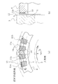
- FIG. 4 illustrates the sealed fluid housing block and the pumping unit in FIG. 3 and shows a state during operation.
- FIG. 4 (a) is an enlarged plan view of the main part
- FIG. FIG. 5 is a sectional view taken along line XX in FIG.
- the stationary ring 6 is indicated by a solid line
- the rotating ring 3 that is a counterpart sliding member is indicated by a two-dot chain line
- the rotating ring 3 rotates in the R direction.
- the plurality of sealed fluid storage blocks 10 are separated from the sealed fluid storage blocks 10 adjacent to each other in the circumferential direction by the sliding surface S, and the sliding surface S is also provided on the atmosphere side. Due to the lack of communication. Further, as shown in FIG.
- the sealed fluid accommodation block 10 is formed in a part of the sliding surface S in the radial direction, has a concave shape so as to accommodate the sealed fluid, and slides.
- the surface S has a step and communicates directly with the sealed fluid housing space via the outer peripheral side 12. For this reason, since the sliding surfaces of the stationary ring 6 and the rotating ring 3 are in a solid contact state when stationary, the sealing performance is maintained by the sliding surfaces continuous in the circumferential direction.
- the sealed fluid is taken into the sealed fluid housing block 10 as indicated by an arrow with a two-dot chain line.
- the linear irregularities formed in the pumping portion 11 in the figure, representative linear irregularities are shown as the linear irregularities.
- the sliding surface S is inclined with respect to the sliding direction, in other words, the rotational tangential direction of the sliding surface S at a predetermined angle ⁇ (in the case of curved irregularities, the angle formed by the tangent.
- the predetermined angle ⁇ is preferably in the range of 10 ° to 80 ° in both the inner diameter direction and the outer diameter direction with respect to the rotational tangent of the sliding surface S.
- each pumping unit 11 is set to an appropriate specific inclination angle ⁇ according to the required lubricity, sliding conditions, and the like. It is effective to obtain a stable sliding characteristic by unifying the inclination angle of the unevenness.
- the inclination angle ⁇ with respect to the rotational tangent of the unevenness in each of the plurality of pumping portions 11 is defined as an optimal specific angle.
- the sliding direction of the sliding surface S is both forward and reverse directions
- the first surface having irregularities that incline with respect to the rotational tangent at a first angle that provides appropriate sliding characteristics when rotating in one direction. It is desirable to mix one pumping portion and a second pumping portion having irregularities that are inclined with respect to the rotation tangent at a second angle that provides appropriate sliding characteristics when rotating in the opposite direction. With such a configuration, appropriate sliding characteristics can be obtained when the sliding surface S rotates in both forward and reverse directions.
- the inclination angle ⁇ of each unevenness between the suction pumping unit 11a and the discharge pumping unit 11b is symmetric with respect to the rotation tangent. It is preferable to form it at an angle. Further, it is preferable that the suction pumping portion 11a and the discharge pumping portion 11b are formed so as to be alternately arranged along the circumferential direction of the sliding surface S.
- the sliding surface S shown in FIGS. 1 and 2 is a configuration of the sliding surface S that is suitable when the sliding surface S rotates in both directions. Note that the suction pumping portions 11a and the discharge pumping portions 11b do not have to be alternately arranged along the circumferential direction of the sliding surface S. For example, two suction pumping portions 11a and one discharge pumping portion 11b are provided. It may be arranged at a ratio of or may be arranged at an opposite ratio.
- the pumping unit 11 which is a structure (a periodic structure of linear irregularities) in which a plurality of linear irregularities parallel to each other and having a constant pitch are accurately arranged at a predetermined pitch, for example, uses a femtosecond laser.
- the moving surface S is strictly divided into predetermined areas, and further, the direction of the unevenness is precisely controlled in each section.
- a linearly polarized laser beam is irradiated to the substrate with an irradiation intensity near the processing threshold, an uneven shape having a pitch of the order of wavelengths and a groove depth due to interference between incident light and scattered light or plasma waves along the surface of the substrate.
- a periodic structure is formed in a self-organizing manner perpendicular to the polarization direction. At this time, the periodic structure pattern can be formed on the surface by performing the operation while overlapping the femtosecond lasers.
- the directionality can be controlled and the processing position can also be controlled, so it is divided into discrete small sections for each section.
- a desired periodic structure can be formed. That is, if this method is used while rotating the sliding surface of the annular mechanical seal sliding material, a fine periodic pattern can be selectively formed on the sliding surface. Further, in the processing method using the femtosecond laser, it is possible to form unevenness with a depth of submicron order effective for improving the lubricity of the mechanical seal and reducing leakage.
- the formation of the sealed fluid accommodating block 10 and the periodic structure of linear irregularities is not limited to the femtosecond laser, and a picosecond laser or an electron beam may be used.
- the formation of the sealed fluid containing block 10 and the periodic structure of the linear irregularities is performed by rotating the sliding surface of the annular mechanical seal sliding member using a mold having the periodic structure of the linear irregularities. However, it may be performed by stamping or stamping.
- the formation of the sealed fluid accommodation block 10 and the linear uneven structure is performed by etching, and then the linear uneven structure is formed on the bottom of the sealed fluid storage block by a femtosecond laser or the like. Also good.
- the sealed fluid housing block 10 may be formed.
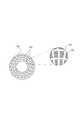
- FIG. 5 is a perspective view illustrating the sealed fluid housing block and the pumping unit in FIGS. 3 and 4 as seen from the sealed fluid side.
- a liquid film h having a thickness of 0.1 ⁇ m to 10 ⁇ m is formed between the sliding surfaces of the fixed ring 6 and the rotating ring 3 as shown in FIG.
- the sealed fluid is taken into the space in the sealed fluid housing block 10 formed by the step d1, and a sufficient liquid film is formed.
- a pumping unit 11 is formed at the bottom of the sealed fluid housing block 10 to cause a liquid flow so that the sealed fluid does not leak to the atmosphere side.
- the sealed fluid housing block 10 is formed, and then the pumping unit 11 is formed.
- the pitch p of the linear irregularities of the pumping part 11 is set according to the viscosity of the fluid to be sealed, but is preferably 0.1 ⁇ m to 100 ⁇ m.
- the pumping portion 11 is formed in parallel with a surface orthogonal to the axis in the circumferential direction and the radial direction.
- the sealing performance is maintained by preventing leakage by the sliding surface S continuous in the circumferential direction.
- the lubricating fluid film can be quickly formed by taking the sealed fluid into the space in the sealed fluid housing block 10, and the sliding torque of the sliding surface S can be reduced to reduce wear. Can do.
- a sealed fluid is taken into a sealed fluid housing block 10 provided with a suction pumping portion 11a, and a discharge pumping portion 11b is provided at a position where the sealed fluid is separated via the sliding surface S.
- the sealed fluid housing block 10 is fed into the sealed fluid housing block 10 and the sealed fluid housing block 10 returns the sealed fluid from the sealed fluid housing block 10 to the sealed fluid side by the action of the discharge pumping portion 11b (indicated by a two-dotted line in FIG. 4A). (See arrows shown.)
- the virtual plane that connects the apexes of the concave and convex portions of the pumping portion 11 is set lower than the sliding surface S, and the virtual plane has a shape having the sliding surface S and the step d1, so that it is formed by the step d1 at startup.
- the lubricating fluid film can be quickly formed by taking the sealed fluid into the remaining space.
- FIG. 6 relates to a second embodiment of the present invention, and shows a sealed fluid storage block 10 and a pumping unit 11 formed on the sliding surface S of the stationary ring 6 of the mechanical seal as exemplified in FIGS. 1 and 2. It is sectional drawing.
- the pumping unit 11 is formed in parallel with the surface orthogonal to the axis in the circumferential direction and the radial direction.
- the suction pumping formed at the bottom of the sealed fluid accommodation block 10 is used.
- the part 11a is formed so that its linear unevenness gradually increases in the circumferential direction toward the rotation direction R of the rotating ring 3 that is the counterpart sliding material, and the discharge pumping part 11b has its linear unevenness Is formed so as to gradually become lower in the rotation direction R of the rotating ring 3 that is the counterpart sliding material.
- the linear unevenness is formed so as to be inclined in the circumferential direction when viewed from the side surface.
- the sealed fluid can be taken in and sent to the discharge pumping unit 11b. In the discharge pumping unit 11b, the fed sealed fluid can be returned to the sealed fluid side further.
- the deepest portion of the virtual plane connecting the vertices of the irregularities of the pumping portion from the sliding surface may be set so as to fall within the range of 0.1h to 10h.
- the pumping 11 formed at the bottom of the sealed fluid containing block 10 can be arbitrarily inclined as necessary in the circumferential direction and / or the radial direction.
- the suction pumping part 11a is formed so as to be gradually lowered toward the inner side in the radial direction to facilitate the suction of the sealed fluid
- the discharge pumping part 11b It can be considered that the sealing fluid is formed so as to gradually increase inward in the radial direction so that the sealed fluid can be easily discharged.
- the deepest portion of the virtual plane connecting the vertices of the irregularities of the pumping portion from the sliding surface may be set to fall within the range of 0.1h to 10h.
- FIG. 7 relates to Embodiment 3 of the present invention, and in the mechanical seal as illustrated in FIGS. 1 and 2, of the sliding surfaces of the stationary ring and the rotating ring, the rotating ring having the larger radial width is shown. It is a top view which shows one Embodiment in case the to-be-sealed fluid accommodation block and pumping part are formed in a sliding surface.
- FIG. 7 among the sliding surfaces of the rotating ring 3 and the stationary ring 6, a plurality of sealed fluids separated in the circumferential direction on the sliding surface S of the rotating ring 3 having a large radial sliding surface width.
- a housing block 10 is formed.
- the plurality of sealed fluid accommodation blocks 10 are formed in a part leaving the outer side and the inner side in the radial direction of the sliding surface S, and a part of the sealed fluid accommodation block 10 on the sealed fluid side is formed. It is formed so as not to be covered with the sliding surface S of the opposite stationary ring 6. Therefore, the sealing performance at the time of stationary is maintained, and the sealed fluid is taken into the sealed fluid housing block 10 at the time of starting.
- the fixed ring 6 slides with a part of the radially inner side of the sealed fluid accommodation block 10 facing each other. What is necessary is just to arrange
- FIG. 8 is a plan view illustrating another example of the pumping unit according to the fourth embodiment of the present invention, and of the sliding surfaces of the stationary ring and the rotating ring, the stationary ring having the smaller radial width. The example in the case where the to-be-sealed fluid accommodation block and the pumping part are formed on the sliding surface is shown.
- the linear uneven pitch Pb of the discharge pumping portion 11b is formed smaller than the linear uneven pitch Pa of the suction pumping portion 11a, and the discharge capacity of the discharge pumping portion 11b is equal to that of the suction pumping portion 11a. It is set larger than the inhalation volume. For this reason, the sealed fluid flowing in from the suction pumping portion 11a and the like is discharged from the discharge pumping portion 11b to the sealed fluid side and is prevented from leaking to the atmosphere side.
- FIG. 8A the linear uneven pitch Pb of the discharge pumping portion 11b is formed smaller than the linear uneven pitch Pa of the suction pumping portion 11a, and the discharge capacity of the discharge pumping portion 11b is equal to that of the suction pumping portion 11a. It is set larger than the inhalation volume. For this reason, the sealed fluid flowing in from the suction pumping portion 11a and the like is discharged from the discharge pumping portion 11b to the sealed fluid side and is prevented from leaking to the atmosphere side.
- the width or depth of the linear unevenness of the discharge pumping portion 11b is formed larger than the width or depth of the linear unevenness of the suction pumping portion 11a, and the discharge capacity of the discharge pumping portion 11b is It is set larger than the suction capacity of the suction pumping part 11a. For this reason, the sealed fluid flowing in from the suction pumping unit 11a and the like is returned from the discharge pumping unit 11b to the sealed fluid side and is prevented from leaking to the atmosphere side.
- FIG. 9 is a plan view illustrating another example of the pumping unit according to the fifth embodiment of the present invention, and of the sliding surfaces of the stationary ring and the rotating ring, the stationary ring having the smaller radial width. The example in the case where the to-be-sealed fluid accommodation block and the pumping part are formed on the sliding surface is shown.
- the suction pumping portion 11a and the discharge pumping portion 11b have the same circumferential length a, but the discharge pumping portion 11b has a radial length b ′ in the radial direction of the suction pumping portion 11a. It is formed larger than the length b, and the discharge capacity of the discharge pumping part 11b is set larger than the suction capacity of the suction pumping part 11a. For this reason, the sealed fluid flowing in from the suction pumping unit 11a and the like is returned from the discharge pumping unit 11b to the sealed fluid side and is prevented from leaking to the atmosphere side.
- FIG. 9A the suction pumping portion 11a and the discharge pumping portion 11b have the same circumferential length a, but the discharge pumping portion 11b has a radial length b ′ in the radial direction of the suction pumping portion 11a. It is formed larger than the length b, and the discharge capacity of the discharge pumping part 11b is set larger than the suction capacity of the suction pumping part 11a
- the suction pumping portion 11a and the discharge pumping portion 11b have the same radial length b, but the discharge pumping portion 11b has a circumferential length a ′ that is the circumference of the suction pumping portion 11a.
- the discharge capacity of the discharge pumping section 11b is set to be larger than the suction capacity of the suction pumping section 11a. For this reason, the sealed fluid flowing in from the suction pumping unit 11a and the like is returned from the discharge pumping unit 11b to the sealed fluid side and is prevented from leaking to the atmosphere side.
- the circumferential length or radial length of the discharge pumping portion 11b is formed larger than the circumferential length or radial length of the suction pumping portion 11a, and the discharge pumping portion 11b
- the discharge capacity may be set larger than the suction capacity of the suction pumping unit 11a.
- FIG. 10 is a perspective view of another example of the pumping unit according to the sixth embodiment of the present invention viewed from the sealed fluid side, and is a radial view of the sliding surfaces of the stationary ring and the rotating ring.
- An example in which a sealed fluid housing block and a pumping portion are formed on the sliding surface of the stationary ring having a smaller width is shown.
- the pumping unit 11 formed at the bottom of the sealed fluid housing block 10 is configured to communicate with the sealed fluid. However, since the sealed fluid housing block 10 has a very shallow depth, the suction pumping unit 11a is sealed.
- hydrophilization is performed along the surface of the concavo-convex part of the pumping part 11 (the suction pumping part 11 a and the discharge pumping part 11 b) formed at the bottom of the sealed fluid housing block 10 to control wettability.
- the sealed fluid is improved so as to easily flow into the pumping unit 11.
- hatching which shows that the hydrophilization process is performed may be seen as filling the recessed part of the pumping part 11, hatching is attached
- the hydrophilic means include the following. (1) Hydrophilization by coating a hydrophilic substance (2) Hydrophilization by roughening the surface (increasing irregularities) and increasing the surface area (3) Photocatalyst (including plasma treatment) Hydrophilization by chemical reaction
- hydrophilic coating materials include ceramics such as silica, alumina, zirconia and titania, organic substances such as fatty acid esters, fatty acid ethers, sulfate esters, phosphate esters and sulfates, and on the surface. Those having a hydrophilic group (fatty acid, carboxylic acid residue, etc.) can be mentioned.
- the coating method includes application, sol-gel method, plasma treatment, PVD, CVD, and shot peening, and a method using a photocatalyst is also possible.
- FIG. 11 shows an example in which the sealed fluid accommodation block and the pumping portion are formed on the sliding surface of the stationary ring having the smaller radial width among the sliding surfaces of the stationary ring and the rotating ring.
- An annular water repellent coating 16 is provided on the sliding portion of the sliding surface S on the atmosphere side.
- FIG. 11 shows the case where the hydrophilic coating 15 shown in the sixth embodiment is provided in the pumping unit 11 (the suction pumping unit 11a and the discharge pumping unit 11b), but this is not always necessary, Of course, the aqueous coating 16 may be provided alone.
- the hydrophilic coating 15 shown in the sixth embodiment is provided in the pumping unit 11 (the suction pumping unit 11a and the discharge pumping unit 11b), but this is not always necessary, Of course, the aqueous coating 16 may be provided alone.
- FIG. 11 shows an example in which the sealed fluid accommodation block and the pumping portion are formed on the sliding surface of the stationary ring having the smaller radial width among the sliding surfaces of the stationary ring and
- the suction pumping part 11a and the discharge pumping part 11b are hydrophilic, the introduction of the sealed fluid is promoted, the lubricity of the sliding surface S is improved, and the sliding part on the atmosphere side Since it is water repellent, the sealed fluid is prevented from leaking to the atmosphere side.
- FIG. 12 shows various water repellent coatings when a sealed fluid housing block and a pumping portion are formed on a sliding surface of a stationary ring having a smaller radial width among sliding surfaces of a stationary ring and a rotating ring.
- the hydrophilic coating 15 is provided in the pumping portion 11
- the annular water-repellent coating 16 is provided in the sliding portion on the atmosphere side of the sliding surface S where the pumping portion 11 is provided.
- a step corresponding to the thickness of the water repellent coating 16 is formed on the sliding surface provided with the water repellent coating 16, but if the thickness of the water repellent coating 16 is about the thickness of the liquid film on the sliding surface S, the seal is sealed. There is no effect on sex.
- FIG. 12A shows various water repellent coatings when a sealed fluid housing block and a pumping portion are formed on a sliding surface of a stationary ring having a smaller radial width among sliding surfaces of a stationary ring and a rotating ring.
- an annular recess is formed in the sliding portion on the atmosphere side of the sliding surface S on which the pumping portion 11 is provided, and is cut by the thickness of the water repellent coating 16, and the annular recess is repelled.
- An aqueous coating 16 is provided. For this reason, the sliding surface S is flush with no step.
- an annular recess is formed in the sliding portion on the atmosphere side of the sliding surface S provided with the pumping portion 11, and the thickness is larger than that of the water repellent coating 16.
- An aqueous coating 16 is provided. In this case, the water-repellent coating 16 is not in contact with the counterpart sliding material, but if the gap is 1 ⁇ m or less, the leakage of the sealed fluid can be sufficiently prevented.
- FIG. 12D an annular recess that is cut by the thickness of the water repellent coating 16 is formed in the sliding portion on the atmosphere side of each sliding surface S, and the water repellent coating 16 is provided in the annular recess. It has been. In this case, leakage of the sealed fluid to the atmosphere side is further prevented.
- FIG. 13 shows various water-repellent coatings in the case where the sealed fluid housing block and the pumping portion are formed on the sliding surface of the rotating ring having the larger radial width among the sliding surfaces of the stationary ring and the rotating ring.
- the hydrophilic coating 15 is provided in the pumping portion 11
- the annular water-repellent coating 16 is provided in the sliding portion on the atmosphere side of the sliding surface S where the pumping portion 11 is provided.
- a step corresponding to the thickness of the water repellent coating 16 is formed on the sliding surface provided with the water repellent coating 16, but if the thickness of the water repellent coating 16 is about the thickness of the liquid film on the sliding surface S, the seal is sealed. There is no effect on sex.
- FIG. 13A the hydrophilic coating 15 is provided in the pumping portion 11
- the annular water-repellent coating 16 is provided in the sliding portion on the atmosphere side of the sliding surface S where the pumping portion 11 is provided.
- a step corresponding to the thickness of the water repellent coating 16 is
- an annular recess that is cut by the thickness of the water repellent coating 16 is formed in the sliding portion on the atmosphere side of the sliding surface S on which the pumping portion 11 is provided.
- An aqueous coating 16 is provided. For this reason, the sliding surface S is flush with no step.
- an annular recess is formed in the sliding portion on the atmosphere side of the sliding surface S provided with the pumping portion 11, which is shaved more than the thickness of the water repellent coating 16.
- An aqueous coating 16 is provided. In this case, the water-repellent coating 16 is not in contact with the counterpart sliding material, but if the gap is 1 ⁇ m or less, the leakage of the sealed fluid can be sufficiently prevented.
- FIG. 13 (b) an annular recess that is cut by the thickness of the water repellent coating 16 is formed in the sliding portion on the atmosphere side of the sliding surface S on which the pumping portion 11 is provided.
- An aqueous coating 16 is provided.
- the water-repellent coating 16 is not in contact
- annular concave portion that is cut by the thickness of the water repellent coating 16 is formed in the sliding portion on the atmosphere side of each sliding surface S, and the water repellent coating 16 is provided in the annular concave portion. It has been. In this case, leakage of the sealed fluid to the atmosphere side is further prevented.
- the pumping capacity of the discharge pumping unit is larger than the pumping capacity of the suction pumping unit.
- the pumping capacity of the suction pumping unit is set larger than the pumping capacity of the discharge pumping unit with emphasis on lubrication. Also good.
Landscapes
- Engineering & Computer Science (AREA)
- General Engineering & Computer Science (AREA)
- Mechanical Engineering (AREA)
- Mechanical Sealing (AREA)
Abstract
Description
また、低摩擦を実現するとともになじみ過程の短縮化を図ることのできる摺動面構造を提供することを目的として、第1部材の摺動面と第2部材の摺動面とが潤滑剤下で相対的に摺動する摺動面構造であって、第1部材と第2部材との少なくともいずれか一方の摺動面に、複数の凹凸からなるグレーティング部を摺動方向に沿って複数個形成し、摺動方向に沿って隣り合うグレーティング部の周期構造の方向を摺動方向に対して対称とした摺動面構造の発明も知られている(以下「従来技術3」という。特許文献3参照。)。
要するに、従来技術2には、メカニカルシールとして使うことは示唆されておらず、また、仮にメカニカルシールに使うとしても、メカニカルシールの起動時にグレーティング状の周期構造部60に積極的に被密封流体を取り込み、かつ、大気側へ漏らさないという技術思想は開示されていない。
前記固定環または回転環の摺動面のいずれか一方には、円周方向に分離された複数の被密封流体収容ブロックが被密封流体収容空間と連通するように形成され、
前記複数の被密封流体収容ブロックの底部には、固定環と回転環との相対回転摺動によりポンピング作用を生起するポンピング部が形成され、
前記複数の被密封流体収容ブロックの底部に形成されるポンピング部は、被密封流体を吸い込む方向に作用する吸入ポンピング部と被密封流体を吐き出す方向に作用する吐出ポンピング部を備えることを特徴としている。
この特徴によれば、静止時には、固定環及び回転環の摺動面間は固体接触状態となるため、円周方向に連続した摺動面により漏れを防止することによりシール性が維持されるとともに、起動時には、被密封流体収容ブロック内の空間に被密封流体を取り込むことによってすばやく潤滑流体膜を形成することができ、摺動面の摺動トルクを低くし、摩耗を低減することができる。さらに、運転時には、吸入ポンピング部を備えた被密封流体収容ブロック内に被密封流体を取り込み、摺動面により分離された位置にある吐出ポンピング部に摺動面を通して被密封流体を送り込み、この被密封流体を被密封流体側に戻すことにより、摺動面の潤滑性を確保するとともに、漏れを防止し、シール性を保つことができる。
また、本発明のメカニカルシールは、第3に、第1の特徴において、前記固定環及び回転環の摺動面のうち、径方向の幅が大きい方の摺動面に被密封流体収容ブロックが設けられる場合、該被密封流体収容ブロックは摺動面の径方向の外方及び内方を残して一部に形成され、かつ、被密封流体収容ブロックの被密封流体側の一部が相対する摺動面で覆われないように形成されることを特徴としている。
第2、第3の特徴によれば、被密封流体収容ブロックに被密封流体を取り込み、または、被密封流体収容ブロックから被密封流体側に被密封流体を戻すことを容易に行うことができる。
この特徴によれば、線状の凹凸の周期構造で所要のポンピング作用を得ることができるので、ポンピング部の形成を容易に行うことができる。
また、本発明のメカニカルシールは、第5に、第1ないし第4のいずれかの特徴において、前記複数の被密封流体収容ブロックの底部に形成されるポンピング部は、隣接する被密封流体収容ブロックの前記線状の凹凸の方向が当該摺動面の摺動方向に対して対称となるように形成されていることを特徴としている。
この特徴によれば、摺動面が正逆両方向に回転する場合に好適である。
この特徴によれば、その方向性の制御が可能であり、加工位置の制御も可能であるため、離散的な小区画に分けて各区画ごとに所望の周期構造の形成ができる。
また、本発明のメカニカルシールは、第7に、第1ないし第5のいずれかの特徴において、前記被密封流体収容ブロック及びポンピング部の線状の凹凸の周期構造は、スタンプまたは刻印により形成されることを特徴としている。
この特徴によれば、線状の凹凸の周期構造を能率良く行うことができる。
また、本発明のメカニカルシールは、第8に、第1ないし第5のいずれかの特徴において、前記被密封流体収容ブロックはエッチングにより形成され、ポンピング部の線状の凹凸の周期構造は、ピコ秒またはフェムト秒レーザの照射により形成されることを特徴としている。
また、本発明のメカニカルシールは、第9に、第1ないし第5のいずれかの特徴において、前記被密封流体収容ブロックはメッキまたは成膜により形成され、ポンピング部の線状の凹凸の周期構造は、ピコ秒またはフェムト秒レーザの照射により形成されることを特徴としている。
第8及び第9の特徴によれば、被密封流体収容ブロックの形成及び線状の凹凸の周期構造の形成を、製造設備に適した手段で柔軟に行うことができる。
この特徴によれば、液膜厚さに応じた最適なポンピング部を得ることができる。
また、本発明のメカニカルシールは、第12に、第11の特徴において、前記吸入ポンピング部は、側面視において線状の凹凸が相手側摺動部材の回転方向に向かって次第に高くなるように形成され、吐出ポンピング部は、側面視において線状の凹凸が相手側摺動部材の回転方向に向かって次第に低くなるように形成されていることを特徴としている。
また、本発明のメカニカルシールは、第13に、第11または12の特徴において、前記吸入ポンピング部は、側面視において線状の凹凸が内周方向に向かって次第に低くなるように形成され、吐出ポンピング部は、側面視において線状の凹凸が外周方向に向かって次第に低くなるように形成されていることを特徴としている。
第11ないし第13の特徴によれば、吸入ポンピング部においては、より一層、被密封流体を取り込んで吐出ポンピング部に送り込むことができ、また、吐出ポンピング部においては、送り込まれた被密封流体を、より一層、被密封流体側に戻すことができる。
また、本発明のメカニカルシールは、第15に、第4ないし第14のいずれかの特徴において、前記複数の被密封流体収容ブロックの底部に形成されるポンピング部において、前記吐出ポンピング部の線状の凹凸のピッチが吸入ポンピング部の線状の凹凸のピッチより小さく形成されていることを特徴としている。
また、本発明のメカニカルシールは、第16に、第4ないし第15のいずれかの特徴において、前記複数の被密封流体収容ブロックの底部に形成されるポンピング部において、前記吐出ポンピング部の線状の凹凸の幅または深さが吸入ポンピング部の線状の凹凸の幅または深さより大きく形成されていることを特徴としている。
また、本発明のメカニカルシールは、第17に、第1ないし第16のいずれかの特徴において、前記複数の被密封流体収容ブロックの底部に形成されるポンピング部において、前記吐出ポンピング部の径方向の長さまたは円周方向の長さが吸入ポンピング部の径方向の長さまたは円周方向の長さより大きく形成されていることを特徴としている。
第14の特徴によれば、吸入ポンピング部のポンピング容量と吐出ポンピング部のポンピング容量とを同等、または、いずれか一方のポンピング容量を大きく設定することができるため、メカニカルシールの使用態様に応じて吸入または吐出のポンピング容量を自由に設定することができる。
また、第15ないし第17の特徴によれば、吐出ポンピング部の吐出容量が吸入ポンピング部の吸入容量より大きく設定されているため、吸入ポンピング部等からの流入する被密封流体は吐出ポンピング部から被密封流体側に戻され、大気側に漏洩することが防止される。
この特徴によれば、被密封流体をポンピング部に導入し易く、また、防汚効果を奏する。さらに、ポンピング部に親水性コーティングを設けて堆積物の発生を防止することで漏れの予防につながる。
また、本発明のメカニカルシールは、第19に、第1ないし第18のいずれかの特徴において、前記固定環と回転環との摺動面の大気側の摺動部において、少なくとポンピング部の形成された摺動面の大気側の摺動部には撥水化加工が施されていることを特徴としている。
この特徴によれば、大気側に被密封流体が漏洩することを一層防止することができる。
(1)上記第1~第5の特徴により、静止時には、固定環及び回転環の摺動面間は固体接触状態となるため、円周方向に連続した摺動面により漏れを防止することによりシール性が維持されるとともに、起動時には、被密封流体収容ブロック内の空間に被密封流体を取り込むことによってすばやく潤滑流体膜を形成することができ、摺動面の摺動トルクを低くし、摩耗を低減することができる。さらに、運転時には、吸入ポンピング部を備えた被密封流体収容ブロック内に被密封流体を取り込み、摺動面により分離された位置にある吐出ポンピング部に摺動面を通して被密封流体を送り込み、この被密封流体を被密封流体側に戻すことにより、摺動面の潤滑性を確保するとともに、漏れを防止し、シール性を保つことができる。
(2)上記第6~第9の特徴により、ポンピング部の線状の凹凸の周期構造を、容易かつ正確に設けることができる。
(3)上記第10の特徴により、上記(1)の効果を最良のものとすることができる。
(4)上記第11~第13の特徴により、吸入ポンピング部においては、より一層、被密封流体を取り込んで吐出ポンピング部に送り込むことができ、吐出ポンピング部においては、送り込まれた被密封流体を、より一層、被密封流体側に戻すことができるため、シール性及び潤滑性を一層高めることができる。
(5)上記第14の特徴によれば、吸入ポンピング部のポンピング容量と吐出ポンピング部のポンピング容量とを同等、または、いずれか一方のポンピング容量を大きく設定することができるため、メカニカルシールの使用態様に応じて吸入または吐出のポンピング容量を自由に設定することができる。
また、上記第15ないし第17の特徴によれば、吐出ポンピング部の吐出容量が吸入ポンピング部の吸入容量より大きく設定されているため、吸入ポンピング部等からの流入する被密封流体は吐出ポンピング部から被密封流体側に戻され、大気側に漏洩することが防止される。
(6)上記第18の特徴によれば、被密封流体をポンピング部に導入し易く、また、防汚効果を奏する。さらに、ポンピング部に親水性コーティングを設けて堆積物の発生を防止することで漏れの予防につながる。
(7)上記第19の特徴によれば、大気側に被密封流体が漏洩することを一層防止することができる。
図1のメカニカルシールは摺動面の外周から内周方向に向かって漏れようとする被密封流体を密封する形式のインサイド形式のものであって、被密封流体側のポンプインペラ(図示省略)を駆動させる回転軸1側にスリーブ2を介してこの回転軸1と一体的に回転可能な状態に設けられた円環状の回転環3と、ポンプのハウジング4に固定されたシールカバー5に非回転状態かつ軸方向移動可能な状態で設けられた円環状の固定環6とが、この固定環6を軸方向に付勢するベローズ7によって、ラッピング等によって鏡面仕上げされた摺動面S同士で密接摺動するようになっている。すなわち、このメカニカルシールは、回転環3と固定環6との互いの摺動面Sにおいて、被密封流体が回転軸1の外周から大気側へ流出するのを防止するものである。
回転環3及び固定環6は、代表的にはSiC(硬質材料)同士またはSiC(硬質材料)とカーボン(軟質材料)の組み合わせで形成されるが、摺動材料にはメカニカルシール用摺動材料として使用されているものは適用可能である。SiCとしては、ボロン、アルミニウム、カーボンなどを焼結助剤とした焼結体をはじめ、成分、組成の異なる2種類以上の相からなる材料、例えば、黒鉛粒子の分散したSiC、SiCとSiからなる反応焼結SiC、SiC-TiC、SiC-TiNなどがあり、カーボンとしては、炭素質と黒鉛質の混合したカーボンをはじめ、樹脂成形カーボン、焼結カーボン、などが利用できる。また、上記摺動材料以外では、金属材料、樹脂材料、表面改質材料(コーティング材料)、複合材料なども適用できる。
図2のメカニカルシールは摺動面の外周から内周方向に向かって漏れようとする冷却水を密封する形式のインサイド形式のものであって、冷却水側のポンプインペラ(図示省略)を駆動させる回転軸1側にスリーブ2を介してこの回転軸1と一体的に回転可能な状態に設けられた円環状の回転環3と、ポンプのハウジング4に非回転状態かつ軸方向移動可能な状態で設けられた円環状の固定環6とが、この固定環6を軸方向に付勢するコイルドウェーブスプリング8及びベローズ9によって、ラッピング等によって鏡面仕上げされた摺動面S同士で密接摺動するようになっている。すなわち、このメカニカルシールは、回転環3と固定環6との互いの摺動面Sにおいて、冷却水が回転軸1の外周から大気側へ流出するのを防止するものである。
図3は、本発明の実施形態1に係り、図1及び2に例示されるようなメカニカルシールにおいて、固定環6及び回転環3の摺動面のうち、径方向の幅が小さい方の固定環6の摺動面Sに被密封流体収容ブロック及びポンピング部が形成される場合の一実施形態示す平面図である。
図3において、固定環6の摺動面Sには、円周方向に分離された複数の被密封流体収容ブロック10が、摺動面Sの径方向の一部であって被密封流体収容空間と外周側12を介して直接連通するように形成されている。
なお、被密封流体側が回転環3及び固定環6の内側に存在するアウトサイド形のメカニカルシールの場合、被密封流体収容ブロック10は、摺動面Sの径方向の一部であって被密封流体収容空間と内周側を介して直接連通するように形成すればよい。
被密封流体収容ブロック10の径方向の幅aは、摺動面Sの径方向の幅Aのおよそ1/3~2/3であり、また、被密封流体収容ブロック10の周方向の角度範囲bは、隣接する被密封流体収容ブロック10、10間に存在する摺動面の角度範囲Bと同じかやや大きく設定される。
なお、本発明において「線状の凹凸」には、直線状の凹凸の他、直線状の凹凸形成の過程で出現される多少彎曲された凹凸、または曲線状の凹凸も包含される。
図4において、固定環6は実線で、また、相手側摺動部材である回転環3は二点差線で示されており、回転環3はR方向に回転する。
図4(a)に示すように、複数の被密封流体収容ブロック10は、円周方向において隣接する被密封流体収容ブロック10と摺動面Sにより分離され、また、大気側とも摺動面Sにより非連通となっている。また、図4(b)に示すように、被密封流体収容ブロック10は、摺動面Sの径方向の一部に形成されており、被密封流体を収容できるように凹状をなし、摺動面Sと段差を有し、被密封流体収容空間とは外周側12を介して直接連通している。このため、静止時には、固定環6及び回転環3の摺動面間は固体接触状態となるため、円周方向に連続した摺動面によりシール性が維持されるとともに、起動時においては、図4(a)において二点差線の矢印で示すように、被密封流体収容ブロック10へ被密封流体の取り込みが行われるようになっている。
さらに、図4(a)に示すように、ポンピング部11に形成される線状の凹凸(図においては、線状の凹凸として代表的な直線状の凹凸を示している。以下同じ。)は、摺動面Sの摺動方向、換言すれば摺動面Sの回転接線方向に対して所定の角度θ(曲線状の凹凸の場合は接線のなす角度である。以下同じ。)で傾斜するように形成される。所定の角度θは、摺動面Sの回転接線に対して内径方向及び外径方向の両方向において各々10°~80°の範囲であることが好ましい。
また、吸入ポンピング部11aと吐出ポンピング部11bとは、摺動面Sの周方向に沿って交互に配置されるように形成するのが好適である。
図1及び図2に示す摺動面Sは、そのような摺動面Sが両方向へ回転する場合に好適な摺動面Sの構成である。
なお、吸入ポンピング部11aと吐出ポンピング部11bとは、摺動面Sの周方向に沿って交互に配置されなくてもよく、例えば、吸入ポンピング部11aが2個、吐出ポンピング部11bが1個の割合で配置されても、あるいは、逆の割合で配置されてもよい。
加工しきい値近傍の照射強度で直線偏光のレーザを基板に照射すると、入射光と基板の表面に沿った散乱光又はプラズマ波の干渉により、波長オーダーのピッチと溝深さを持つ凹凸状の周期構造が偏光方向に直交して自己組織的に形成される。この時、フェムト秒レーザをオーバーラップさせながら操作を行うことにより、その周期構造パターンを表面に形成することができる。
さらに、前記被密封流体収容ブロック10及び線状の凹凸の周期構造の形成は、エッチングで行い、その後、フェムト秒レーザなどにより被密封流体収容ブロック底部に線状の凹凸の周期構造を形成させてもよい。さらに、フェムト秒レーザなどにより、摺動面に線状の凹凸の周期構造のみ形成させ、その後、線状の凹凸の周期構造が形成されていない摺動面にメッキあるいは成膜を行うことで、被密封流体収容ブロック10を形成させてもよい。
固定環6と回転環3との摺動面間には、図4(b)に示すように、回転初期から運転時において、厚さ0.1μm~10μmの液膜hが形成されるが、その場合、ポンピング部11において、凹凸の頂点を結ぶような仮想平面をとると、該仮想平面は液膜hに応じて摺動面Sよりd1=0.1h~10h低く設定され、仮想平面が摺動面Sと段差d1を形成する形状となっている。この段差d1により形成された被密封流体収容ブロック10内の空間に被密封流体が取り込まれ、十分な液膜が形成される。しかし、十分な液膜を形成するだけでは圧力差により漏れが発生することになる。このため、被密封流体収容ブロック10の底部には、被密封流体が大気側に漏れないように液体の流れを生起させるポンピング部11が形成されているのである。
フェムト秒レーザによる場合には、まず、被密封流体収容ブロック10が形成され、その後続いて、ポンピング部11が形成される。
また、凹凸の頂点と底部との深さd2は、d2=0.1h~10hの範囲が望ましい。
ポンピング部11の線状の凹凸のピッチpは、被密封流体の粘度に応じて設定されるが、0.1μm~100μmが望ましい。被密封流体の粘度が高い場合、溝内に流体が十分に入り込めるようにピッチpを大きくした方がよい。
なお、図5において、ポンピング部11は、円周方向及び径方向において、軸と直交する面と平行に形成されている。
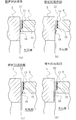
図6は、本発明の実施形態2に係り、図1及び2に例示されるようなメカニカルシールの固定環6の摺動面Sに形成される被密封流体収容ブロック10及びポンピング部11を示す断面図である。
実施形態1において、ポンピング部11は、円周方向及び径方向において軸と直交する面と平行に形成されているが、図6においては、被密封流体収容ブロック10の底部に形成される吸入ポンピング部11aは、周方向において、その線状の凹凸が相手側摺動材である回転環3の回転方向Rに向かって次第に高くなるように形成され、吐出ポンピング部11bは、その線状の凹凸が相手側摺動材である回転環3の回転方向Rに向かって次第に低くなるように形成されている。
このように、線状の凹凸が、平面から見た際の回転接線に対する傾斜に加えて、側面から見ても周方向に傾斜して形成されていることから、吸入ポンピング部11aにおいては、より一層、被密封流体を取り込んで吐出ポンピング部11bに送り込むことができ、また、吐出ポンピング部11bにおいては、送り込まれた被密封流体を、より一層、被密封流体側に戻すことができる。
本例の場合、前記固定環と回転環との摺動面間に形成される液膜厚さをhとした場合、摺動面からのポンピング部の凹凸の頂点を結ぶ仮想平面の最深部及び最浅部の深さが、0.1h~10hの範囲内に入るように設定されればよい。
本例の場合も、前記固定環と回転環との摺動面間に形成される液膜厚さをhとした場合、摺動面からのポンピング部の凹凸の頂点を結ぶ仮想平面の最深部及び最浅部の深さが、0.1h~10hの範囲内に入るように設定されればよい。
図7は、本発明の実施形態3に係り、図1及び2に例示されるようなメカニカルシールにおいて、固定環及び回転環の摺動面のうち、径方向の幅が大きい方の回転環の摺動面に被密封流体収容ブロック及びポンピング部が形成される場合の一実施形態示す平面図である。
図7において、回転環3及び固定環6の摺動面のうち、径方向の摺動面の幅が大きい回転環3の摺動面Sに、円周方向に分離された複数の被密封流体収容ブロック10が形成されている。これら複数の被密封流体収容ブロック10は、摺動面Sの径方向の外方及び内方を残して一部に形成され、かつ、被密封流体収容ブロック10の被密封流体側の一部が相対する固定環6の摺動面Sで覆われないように形成されるものである。このため、静止時のシール性が維持されるとともに、起動時においては、被密封流体収容ブロック10へ被密封流体が取り込まれるものである。
なお、被密封流体側が回転環3及び固定環6の内側に存在するアウトサイド形のメカニカルシールの場合は、被密封流体収容ブロック10の径方向内側の一部が相対する固定環6の摺動面により覆われないように配置すればよい。
図8は、本発明の実施形態4に係り、ポンピング部の他の例を説明する平面図であって、固定環及び回転環の摺動面のうち、径方向の幅が小さい方の固定環の摺動面に被密封流体収容ブロック及びポンピング部が形成される場合の例を示している。
メカニカルシールの摺動面Sに同じ容量の吸入ポンピング部11a及び吐出ポンピング部11bが形成されている場合、両回転方向のメカニカルシールで利用できるメリットはあるが、被密封流体の圧力が高い場合、吐出ポンピング部11bからの吐出量より吸入ポンピング部11a等からの流入量が上回り漏れ量が増加する恐れがある。
また、図8(b)では、吐出ポンピング部11bの線状の凹凸の幅または深さが吸入ポンピング部11aの線状の凹凸の幅または深さより大きく形成され、吐出ポンピング部11bの吐出容量が吸入ポンピング部11aの吸入容量より大きく設定されている。このため、吸入ポンピング部11a等からの流入する被密封流体は吐出ポンピング部11bから被密封流体側に戻され、大気側に漏洩することが防止される。
図9は、本発明の実施形態5に係り、ポンピング部の他の例を説明する平面図であって、固定環及び回転環の摺動面のうち、径方向の幅が小さい方の固定環の摺動面に被密封流体収容ブロック及びポンピング部が形成される場合の例を示している。
メカニカルシールの摺動面Sに同じ容量の吸入ポンピング部11a及び吐出ポンピング部11bが形成されている場合、両回転方向のメカニカルシールで利用できるメリットはあるが、被密封流体の圧力が高い場合、吐出ポンピング部11bからの吐出量より吸入ポンピング部11a等からの流入量が上回り漏れ量が増加する恐れがある。
また、図9(b)では、吸入ポンピング部11a及び吐出ポンピング部11bの径方向の長さbは同じであるが、吐出ポンピング部11bの周方向の長さa’が吸入ポンピング部11aの周方向の長さaより大きく形成され、吐出ポンピング部11bの吐出容量が吸入ポンピング部11aの吸入容量より大きく設定されている。このため、吸入ポンピング部11a等からの流入する被密封流体は吐出ポンピング部11bから被密封流体側に戻され、大気側に漏洩することが防止される。
さらに、図示されていないが、吐出ポンピング部11bの周方向の長さまたは径方向の長さを吸入ポンピング部11aの周方向の長さまたは径方向の長さより大きく形成し、吐出ポンピング部11bの吐出容量を吸入ポンピング部11aの吸入容量より大きく設定してもよい。
図10は、本発明の実施形態6に係り、ポンピング部の他の例を説明する被密封流体側から見た斜視図であって、固定環及び回転環の摺動面のうち、径方向の幅が小さい方の固定環の摺動面に被密封流体収容ブロック及びポンピング部が形成される場合の例を示している。
被密封流体収容ブロック10の底部に形成されたポンピング部11は被密封流体に連通する構成となっているが、被密封流体収容ブロック10の深さは極浅いことから吸入ポンピング部11aの被密封流体が入り込みにくく、また、摺動面Sの隙間が狭いため、吸入ポンピング部11aから出た被密封流体が吐出ポンピング部11bに入り込む際も入り込みにくいと想定される。一方、ポンピング部11がその能力を発揮するためには、ポンピング部11に被密封流体が流れ込みやすいことが必要である。
なお、図10において、親水化加工が施されていることを示すハッチングがポンピング部11の凹部を埋めているように見られる恐れがあるが、ハッチングは凹凸部の表面に沿って付されているのであり、ポンピング部11の親水化加工は凹凸部の表面に沿って施されているものである。
この親水化の手段としては、以下のものがある。
(1)親水性の物質をコーティングすることによる親水化
(2)表面を極微細に粗し(凹凸を増やし)表面積を増加させることによる親水化
(3)光触媒(プラズマ処理を含む)などを用いた化学反応による親水化
また、コーティング方法としては、塗布、ゾル-ゲル法、プラズマ処理、PVD、CVD及びショットピーニングがあり、光触媒を用いた方法も可能である。
図11ないし図13を参照しながら、本発明の実施形態7について説明する。
図11は、固定環及び回転環の摺動面のうち、径方向の幅が小さい方の固定環の摺動面に被密封流体収容ブロック及びポンピング部が形成される場合の例を示しているものであって、摺動面Sの大気側の摺動部には環状の撥水性コーテング16が設けられている。
なお、図11では、ポンピング部11(吸入ポンピング部11a及び吐出ポンピング部11b)には実施形態6で示した親水性コーテング15が設けられている場合を示しているが、必ずしも必要ではなく、撥水性コーテング16が単独で設けられてもよいことはもちろんである。
図11の例では、吸入ポンピング部11a及び吐出ポンピング部11bは親水性であるから被密封流体の導入が促進され、摺動面Sの潤滑性が良好になり、また、大気側の摺動部は撥水性であるから大気側に被密封流体が漏洩することが防止される。
図12(a)では、ポンピング部11に親水性コーテング15が設けられ、ポンピング部11の設けられた摺動面Sの大気側の摺動部に環状の撥水性コーテング16が設けられている。撥水性コーテング16が設けられた摺動面には撥水性コーテング16の厚さ分の段差ができるが、撥水性コーテング16の厚さが摺動面Sの液膜の厚さ程度であればシール性に影響はない。
図12(b)では、ポンピング部11の設けられた摺動面Sの大気側の摺動部には撥水性コーテング16の厚さ分だけ削られた環状凹部が形成され、その環状凹部に撥水性コーテング16が設けられている。このため、摺動面Sは面一となり段差はない。
図12(c)では、ポンピング部11の設けられた摺動面Sの大気側の摺動部には撥水性コーテング16の厚さ以上に削られた環状凹部が形成され、その環状凹部に撥水性コーテング16が設けられている。この場合、撥水性コーテング16は相手側摺動材と非接触となるが、1μm以下の隙間であれば被密封流体の漏洩は十分防止可能である。
図12(d)では、それぞれの摺動面Sの大気側の摺動部には撥水性コーテング16の厚さ分だけ削られた環状凹部が形成され、その環状凹部に撥水性コーテング16が設けられている。この場合、大気側への被密封流体の漏洩は一層防止される。
図13(a)では、ポンピング部11に親水性コーテング15が設けられ、ポンピング部11の設けられた摺動面Sの大気側の摺動部に環状の撥水性コーテング16が設けられている。撥水性コーテング16が設けられた摺動面には撥水性コーテング16の厚さ分の段差ができるが、撥水性コーテング16の厚さが摺動面Sの液膜の厚さ程度であればシール性に影響はない。
図13(b)では、ポンピング部11の設けられた摺動面Sの大気側の摺動部には撥水性コーテング16の厚さ分だけ削られた環状凹部が形成され、その環状凹部に撥水性コーテング16が設けられている。このため、摺動面Sは面一となり段差はない。
図13(c)では、ポンピング部11の設けられた摺動面Sの大気側の摺動部には撥水性コーテング16の厚さ以上に削られた環状凹部が形成され、その環状凹部に撥水性コーテング16が設けられている。この場合、撥水性コーテング16は相手側摺動材と非接触となるが、1μm以下の隙間であれば被密封流体の漏洩は十分防止可能である。
図13(d)では、それぞれの摺動面Sの大気側の摺動部には撥水性コーテング16の厚さ分だけ削られた環状凹部が形成され、その環状凹部に撥水性コーテング16が設けられている。この場合、大気側への被密封流体の漏洩は一層防止される。
2 スリーブ
3 回転環
4 ハウジング
5 シールカバー
6 固定環
7 ベローズ
8 コイルドウェーブスプリング
9 ベローズ
10 被密封流体収容ブロック
11 ポンピング部
11a 吸入ポンピング部
11b 吐出ポンピング部
12 外周側
15 親水性コーテング
16 撥水性コーテング
S 摺動面
Claims (19)
- 固定側に固定される円環状の固定環と、回転軸とともに回転する円環状の回転環とが対向して各摺動面を相対回転させることにより、当該相対回転摺動する前記摺動面の径方向の一方側に存在する被密封流体を密封するメカニカルシールにおいて、
前記固定環または回転環の摺動面のいずれか一方には、円周方向に分離された複数の被密封流体収容ブロックが被密封流体収容空間と連通するように形成され、
前記複数の被密封流体収容ブロックの底部には、固定環と回転環との相対回転摺動によりポンピング作用を生起するポンピング部が形成され、
前記複数の被密封流体収容ブロックの底部に形成されるポンピング部は、被密封流体を吸い込む方向に作用する吸入ポンピング部と被密封流体を吐き出す方向に作用する吐出ポンピング部を備えることを特徴とするメカニカルシール。 - 前記固定環及び回転環の摺動面のうち、径方向の幅が小さい方の摺動面に被密封流体収容ブロックが設けられる場合、該被密封流体収容ブロックは摺動面の径方向の一部であって、被密封流体収容空間と外周側または内周側を介して直接連通するように形成されることを特徴とする請求項1記載のメカニカルシール。
- 前記固定環及び回転環の摺動面のうち、径方向の幅が大きい方の摺動面に被密封流体収容ブロックが設けられる場合、該被密封流体収容ブロックは摺動面の径方向の外方及び内方を残して一部に形成され、かつ、被密封流体収容ブロックの被密封流体側の一部が相対する摺動面で覆われないように形成されることを特徴とする請求項1記載のメカニカルシール。
- 前記ポンピング部は、線状の凹凸の周期構造をしており、前記線状の凹凸は、当該凹凸の方向が当該摺動面の摺動方向に対して所定の角度傾斜するように形成されていることを特徴とする請求項1ないし3のいずれか1項に記載のメカニカルシール。
- 前記複数の被密封流体収容ブロックの底部に形成されるポンピング部は、隣接する被密封流体収容ブロックの前記線状の凹凸の方向が当該摺動面の摺動方向に対して対称となるように形成されていることを特徴とする請求項1ないし4のいずれか1項に記載のメカニカルシール。
- 前記被密封流体収容ブロック及びポンピング部の線状の凹凸の周期構造は、ピコ秒レーザまたはフェムト秒レーザの照射により形成されることを特徴とする請求項1ないし5のいずれか1項に記載のメカニカルシール。
- 前記被密封流体収容ブロック及びポンピング部の線状の凹凸の周期構造は、スタンプまたは刻印により形成されることを特徴とする請求項1ないし5のいずれか1項に記載のメカニカルシール。
- 前記被密封流体収容ブロックはエッチングにより形成され、ポンピング部の線状の凹凸の周期構造は、ピコ秒レーザまたはフェムト秒レーザの照射により形成されることを特徴とする請求項1ないし5のいずれか1項に記載のメカニカルシール。
- 前記被密封流体収容ブロックはメッキまたは成膜により形成され、ポンピング部の線状の凹凸の周期構造は、ピコ秒レーザまたはフェムト秒レーザの照射により形成されることを特徴とする請求項1ないし5のいずれか1項に記載のメカニカルシール。
- 前記固定環と回転環との摺動面間に形成される液膜厚さをhとした場合、摺動面からのポンピング部の凹凸の頂点を結ぶ仮想平面の深さd1が、d1=0.1h~10hの範囲に設定され、また、ポンピング部の凹凸の深さd2が、d2=0.1h~10hの範囲に設定されることを特徴とする請求項1ないし8のいずれか1項に記載のメカニカルシール。
- 前記吸入ポンピング部及び吐出ポンピング部は、側面視において線状の凹凸が円周方向または/及び径方向において、それぞれ任意に傾斜して形成されていることを特徴とする請求項1ないし10のいずれか1項に記載のメカニカルシール。
- 前記吸入ポンピング部は、側面視において線状の凹凸が相手側摺動部材の回転方向に向かって次第に高くなるように形成され、吐出ポンピング部は、側面視において線状の凹凸が相手側摺動部材の回転方向に向かって次第に低くなるように形成されていることを特徴とする請求項11記載のメカニカルシール。
- 前記吸入ポンピング部は、側面視において線状の凹凸が内周方向に向かって次第に低くなるように形成され、吐出ポンピング部は、側面視において線状の凹凸が外周方向に向かって次第に低くなるように形成されていることを特徴とする請求項11または12記載のメカニカルシール。
- 前記複数の被密封流体収容ブロックの底部に形成されるポンピング部において、前記吸入ポンピング部のポンピング容量と吐出ポンピング部のポンピング容量とが同等、または、いずれか一方のポンピング容量が大きく設定されていることを特徴とする請求項1ないし13のいずれか1項に記載のメカニカルシール。
- 前記複数の被密封流体収容ブロックの底部に形成されるポンピング部において、前記吐出ポンピング部の線状の凹凸のピッチが吸入ポンピング部の線状の凹凸のピッチより小さく形成されていることを特徴とする請求項4ないし14のいずれか1項に記載のメカニカルシール。
- 前記複数の被密封流体収容ブロックの底部に形成されるポンピング部において、前記吐出ポンピング部の線状の凹凸の幅または深さが吸入ポンピング部の線状の凹凸の幅または深さより大きく形成されていることを特徴とする請求項4ないし15のいずれか1項に記載のメカニカルシール。
- 前記複数の被密封流体収容ブロックの底部に形成されるポンピング部において、前記吐出ポンピング部の径方向の長さまたは円周方向の長さが吸入ポンピング部の径方向の長さまたは円周方向の長さより大きく形成されていることを特徴とする請求項1ないし16のいずれか1項に記載のメカニカルシール。
- 前記複数の被密封流体収容ブロックの底部に形成されるポンピング部には親水化加工が施されていることを特徴とする請求項1ないし17のいずれか1項に記載のメカニカルシール。
- 前記固定環と回転環との摺動面の大気側の摺動部において、少なくとポンピング部の形成された摺動面の大気側の摺動部には撥水化加工が施されていることを特徴とする請求項1ないし18のいずれか1項に記載のメカニカルシール。
Priority Applications (5)
| Application Number | Priority Date | Filing Date | Title |
|---|---|---|---|
| EP12821851.8A EP2740974B1 (en) | 2011-08-05 | 2012-07-27 | Mechanical seal |
| JP2013527961A JP5936079B2 (ja) | 2011-08-05 | 2012-07-27 | メカニカルシール |
| US14/234,200 US9982784B2 (en) | 2011-08-05 | 2012-07-27 | Mechanical seal |
| KR1020137030778A KR101513278B1 (ko) | 2011-08-05 | 2012-07-27 | 메커니컬 실 |
| CN201280031364.5A CN103620277B (zh) | 2011-08-05 | 2012-07-27 | 机械密封件 |
Applications Claiming Priority (2)
| Application Number | Priority Date | Filing Date | Title |
|---|---|---|---|
| JP2011-171414 | 2011-08-05 | ||
| JP2011171414 | 2011-08-05 |
Publications (1)
| Publication Number | Publication Date |
|---|---|
| WO2013021839A1 true WO2013021839A1 (ja) | 2013-02-14 |
Family
ID=47668352
Family Applications (1)
| Application Number | Title | Priority Date | Filing Date |
|---|---|---|---|
| PCT/JP2012/069144 WO2013021839A1 (ja) | 2011-08-05 | 2012-07-27 | メカニカルシール |
Country Status (6)
| Country | Link |
|---|---|
| US (1) | US9982784B2 (ja) |
| EP (1) | EP2740974B1 (ja) |
| JP (3) | JP5936079B2 (ja) |
| KR (1) | KR101513278B1 (ja) |
| CN (1) | CN103620277B (ja) |
| WO (1) | WO2013021839A1 (ja) |
Cited By (2)
| Publication number | Priority date | Publication date | Assignee | Title |
|---|---|---|---|---|
| WO2019013233A1 (ja) * | 2017-07-13 | 2019-01-17 | イーグル工業株式会社 | 摺動部材 |
| US11708911B2 (en) | 2017-10-03 | 2023-07-25 | Eagle Industry Co., Ltd. | Sliding component |
Families Citing this family (24)
| Publication number | Priority date | Publication date | Assignee | Title |
|---|---|---|---|---|
| JP5758378B2 (ja) * | 2010-03-15 | 2015-08-05 | イーグル工業株式会社 | 摺動部材 |
| CN103732956B (zh) * | 2011-09-06 | 2016-03-30 | 伊格尔工业股份有限公司 | 轴封装置 |
| US9234594B2 (en) * | 2012-05-21 | 2016-01-12 | Eagle Industry Co., Ltd. | Sliding component |
| CN104321568B (zh) * | 2012-09-11 | 2017-02-22 | 伊格尔工业股份有限公司 | 滑动部件 |
| EP2853789B1 (en) * | 2012-10-18 | 2019-03-06 | Eagle Industry Co., Ltd. | Slide part |
| JP6168615B2 (ja) * | 2012-11-28 | 2017-08-02 | 国立大学法人 熊本大学 | 軸封装置及びシール部材並びに水力発電装置 |
| EP3190317B1 (en) * | 2014-09-04 | 2022-02-09 | Eagle Industry Co., Ltd. | Mechanical seal |
| WO2016037652A1 (en) * | 2014-09-11 | 2016-03-17 | Aktiebolaget Skf | Dynamic seal |
| US9682441B2 (en) | 2015-06-01 | 2017-06-20 | Caterpillar Inc. | Laser polishing system and method for metal face seal |
| WO2017002774A1 (ja) * | 2015-06-30 | 2017-01-05 | イーグル工業株式会社 | シール装置 |
| JPWO2017010146A1 (ja) * | 2015-07-10 | 2018-04-19 | 株式会社荏原製作所 | 非接触環状シール及びこれを備える回転機械 |
| CN106313926B (zh) * | 2016-09-27 | 2019-01-29 | 清华大学 | 一种改变浸渍石墨表面浸润性能的表面改性方法 |
| EP3617565A4 (en) * | 2017-04-25 | 2020-12-30 | NOK Corporation | WATERPROOFING ELEMENT |
| US11608897B2 (en) | 2018-08-01 | 2023-03-21 | Eagle Industry Co., Ltd. | Slide component |
| WO2020040234A1 (ja) | 2018-08-24 | 2020-02-27 | イーグル工業株式会社 | 摺動部材 |
| US11815184B2 (en) | 2018-11-30 | 2023-11-14 | Eagle Industry Co., Ltd. | Sliding component |
| CN109488769B (zh) * | 2018-12-20 | 2024-01-16 | 丹东克隆集团有限责任公司 | 带双向螺旋泵送环封液循环机构的双端面机械密封 |
| WO2020130087A1 (ja) | 2018-12-21 | 2020-06-25 | イーグル工業株式会社 | 摺動部品 |
| JP7370681B2 (ja) | 2019-02-14 | 2023-10-30 | イーグル工業株式会社 | 摺動部品 |
| US20220099138A1 (en) * | 2019-02-21 | 2022-03-31 | Eagle Industry Co., Ltd. | Sliding components |
| US20220145931A1 (en) * | 2019-04-09 | 2022-05-12 | Eagle Industry Co., Ltd. | Sliding component |
| EP4345342A2 (en) | 2019-07-26 | 2024-04-03 | Eagle Industry Co., Ltd. | Sliding component |
| US20230027772A1 (en) * | 2019-12-17 | 2023-01-26 | Eagle Industry Co., Ltd. | Sliding component |
| WO2024043211A1 (ja) * | 2022-08-23 | 2024-02-29 | イーグル工業株式会社 | メカニカルシール |
Citations (9)
| Publication number | Priority date | Publication date | Assignee | Title |
|---|---|---|---|---|
| JPS61184165U (ja) * | 1985-05-09 | 1986-11-17 | ||
| JPS63118460U (ja) * | 1987-01-27 | 1988-07-30 | ||
| JPH01133572U (ja) * | 1988-03-08 | 1989-09-12 | ||
| JPH0473A (ja) * | 1990-04-17 | 1992-01-06 | Eagle Ind Co Ltd | 両回転式準接触メカニカルシール及びリング摺動面の溝加工方法 |
| JPH0735242A (ja) * | 1993-07-22 | 1995-02-07 | Nippon Pillar Packing Co Ltd | 非接触形軸封装置 |
| JP2004183810A (ja) * | 2002-12-04 | 2004-07-02 | Matsushita Electric Ind Co Ltd | ウォーターポンプ用メカニカルシール |
| JP2009014183A (ja) * | 2007-07-09 | 2009-01-22 | Canon Machinery Inc | 摺動面構造 |
| WO2009087995A1 (ja) * | 2008-01-11 | 2009-07-16 | Eagle Industry Co., Ltd. | メカニカルシール摺動材及びメカニカルシール |
| JP2009250378A (ja) * | 2008-04-08 | 2009-10-29 | Eagle Ind Co Ltd | 液体用のメカニカルシール装置 |
Family Cites Families (19)
| Publication number | Priority date | Publication date | Assignee | Title |
|---|---|---|---|---|
| US3499653A (en) * | 1968-06-05 | 1970-03-10 | Crane Packing Co | Rotary mechanical seal of the gap type |
| US5312117A (en) * | 1977-04-12 | 1994-05-17 | Taiho Kogyo Co., Ltd. | Mechanical seal |
| JPS57161366A (en) * | 1981-03-31 | 1982-10-04 | Eagle Ind Co Ltd | Mechanical seal |
| JPH0128374Y2 (ja) * | 1985-06-03 | 1989-08-29 | ||
| JPH01158270A (ja) * | 1987-12-15 | 1989-06-21 | Mayekawa Mfg Co Ltd | メカニカルシール |
| GB9103217D0 (en) * | 1991-02-15 | 1991-04-03 | Crane John Uk Ltd | Mechanical face seals |
| DE4209484A1 (de) * | 1991-06-12 | 1993-10-21 | Heinz Konrad Prof Dr I Mueller | Gleitringdichtung mit Rückförderwirkung |
| JPH0590050U (ja) * | 1992-02-06 | 1993-12-07 | イーグル工業株式会社 | 両方向回転型ガスシール |
| US5533739A (en) * | 1992-06-10 | 1996-07-09 | Durametallic Corporation | Non-contacting seal with centering spring mounted in dovetailed grooved |
| US5501470A (en) * | 1992-12-11 | 1996-03-26 | Nippon Pillar Packing Co., Ltd. | Non-contacting shaft sealing device with grooved face pattern |
| JP2563081B2 (ja) * | 1994-03-22 | 1996-12-11 | 日本ピラー工業株式会社 | 非接触形軸封装置 |
| JPH09329247A (ja) * | 1996-06-11 | 1997-12-22 | Ebara Corp | 非接触端面シール |
| PL187630B1 (pl) * | 1998-12-10 | 2004-08-31 | Anga Uszczelnienia Mechaniczne | Pierścień ślizgowy uszczelnienia mechanicznego czołowego bezstykowego |
| US6446976B1 (en) * | 2000-09-06 | 2002-09-10 | Flowserve Management Company | Hydrodynamic face seal with grooved sealing dam for zero-leakage |
| JP2005121164A (ja) * | 2003-10-17 | 2005-05-12 | Nsk Ltd | シール装置 |
| JP2005188651A (ja) * | 2003-12-25 | 2005-07-14 | Yamada Seisakusho Co Ltd | ウォーターポンプにおけるメカニカルシール |
| KR100965978B1 (ko) * | 2004-08-27 | 2010-06-24 | 한국씰마스타주식회사 | 미케니컬 페이스 씰의 그루브패턴구조 |
| JP4263185B2 (ja) | 2005-09-06 | 2009-05-13 | キヤノンマシナリー株式会社 | 低摩擦しゅう動面 |
| JP4699946B2 (ja) * | 2006-06-09 | 2011-06-15 | イーグル工業株式会社 | メカニカルシール装置 |
-
2012
- 2012-07-27 WO PCT/JP2012/069144 patent/WO2013021839A1/ja active Application Filing
- 2012-07-27 EP EP12821851.8A patent/EP2740974B1/en active Active
- 2012-07-27 CN CN201280031364.5A patent/CN103620277B/zh active Active
- 2012-07-27 KR KR1020137030778A patent/KR101513278B1/ko active IP Right Grant
- 2012-07-27 US US14/234,200 patent/US9982784B2/en active Active
- 2012-07-27 JP JP2013527961A patent/JP5936079B2/ja active Active
-
2015
- 2015-08-07 JP JP2015156967A patent/JP2016028210A/ja active Pending
- 2015-09-24 JP JP2015187040A patent/JP5980396B2/ja active Active
Patent Citations (9)
| Publication number | Priority date | Publication date | Assignee | Title |
|---|---|---|---|---|
| JPS61184165U (ja) * | 1985-05-09 | 1986-11-17 | ||
| JPS63118460U (ja) * | 1987-01-27 | 1988-07-30 | ||
| JPH01133572U (ja) * | 1988-03-08 | 1989-09-12 | ||
| JPH0473A (ja) * | 1990-04-17 | 1992-01-06 | Eagle Ind Co Ltd | 両回転式準接触メカニカルシール及びリング摺動面の溝加工方法 |
| JPH0735242A (ja) * | 1993-07-22 | 1995-02-07 | Nippon Pillar Packing Co Ltd | 非接触形軸封装置 |
| JP2004183810A (ja) * | 2002-12-04 | 2004-07-02 | Matsushita Electric Ind Co Ltd | ウォーターポンプ用メカニカルシール |
| JP2009014183A (ja) * | 2007-07-09 | 2009-01-22 | Canon Machinery Inc | 摺動面構造 |
| WO2009087995A1 (ja) * | 2008-01-11 | 2009-07-16 | Eagle Industry Co., Ltd. | メカニカルシール摺動材及びメカニカルシール |
| JP2009250378A (ja) * | 2008-04-08 | 2009-10-29 | Eagle Ind Co Ltd | 液体用のメカニカルシール装置 |
Cited By (3)
| Publication number | Priority date | Publication date | Assignee | Title |
|---|---|---|---|---|
| WO2019013233A1 (ja) * | 2017-07-13 | 2019-01-17 | イーグル工業株式会社 | 摺動部材 |
| JPWO2019013233A1 (ja) * | 2017-07-13 | 2020-07-09 | イーグル工業株式会社 | 摺動部材 |
| US11708911B2 (en) | 2017-10-03 | 2023-07-25 | Eagle Industry Co., Ltd. | Sliding component |
Also Published As
| Publication number | Publication date |
|---|---|
| JP2016028210A (ja) | 2016-02-25 |
| KR20130140209A (ko) | 2013-12-23 |
| CN103620277A (zh) | 2014-03-05 |
| JP2016014482A (ja) | 2016-01-28 |
| JPWO2013021839A1 (ja) | 2015-03-05 |
| KR101513278B1 (ko) | 2015-04-17 |
| JP5936079B2 (ja) | 2016-06-15 |
| EP2740974A1 (en) | 2014-06-11 |
| US20140167361A1 (en) | 2014-06-19 |
| CN103620277B (zh) | 2016-08-17 |
| EP2740974B1 (en) | 2018-04-18 |
| EP2740974A4 (en) | 2015-07-08 |
| JP5980396B2 (ja) | 2016-08-31 |
| US9982784B2 (en) | 2018-05-29 |
Similar Documents
| Publication | Publication Date | Title |
|---|---|---|
| JP5980396B2 (ja) | メカニカルシール | |
| JP5871289B2 (ja) | 摺動部品 | |
| JP5968889B2 (ja) | 摺動部品 | |
| JP5960145B2 (ja) | 摺動部品及びその製造方法 | |
| JP7179430B2 (ja) | 摺動部品 | |
| JP5980217B2 (ja) | 軸封装置及びその製造方法 | |
| JP5881716B2 (ja) | 摺動部品 | |
| JP5950998B2 (ja) | 軸封装置 | |
| JP5950997B2 (ja) | 軸封装置 | |
| CA2934797C (en) | Electrical corrosion resistant mechanical seal | |
| WO2022190944A1 (ja) | 摺動部品 |
Legal Events
| Date | Code | Title | Description |
|---|---|---|---|
| 121 | Ep: the epo has been informed by wipo that ep was designated in this application |
Ref document number: 12821851 Country of ref document: EP Kind code of ref document: A1 |
|
| ENP | Entry into the national phase |
Ref document number: 2013527961 Country of ref document: JP Kind code of ref document: A |
|
| ENP | Entry into the national phase |
Ref document number: 20137030778 Country of ref document: KR Kind code of ref document: A |
|
| WWE | Wipo information: entry into national phase |
Ref document number: 14234200 Country of ref document: US |
|
| NENP | Non-entry into the national phase |
Ref country code: DE |
|
| WWE | Wipo information: entry into national phase |
Ref document number: 2012821851 Country of ref document: EP |