EP2740974B1 - Mechanical seal - Google Patents
Mechanical seal Download PDFInfo
- Publication number
- EP2740974B1 EP2740974B1 EP12821851.8A EP12821851A EP2740974B1 EP 2740974 B1 EP2740974 B1 EP 2740974B1 EP 12821851 A EP12821851 A EP 12821851A EP 2740974 B1 EP2740974 B1 EP 2740974B1
- Authority
- EP
- European Patent Office
- Prior art keywords
- fluid
- sealed
- pumping parts
- mechanical seal
- pumping
- Prior art date
- Legal status (The legal status is an assumption and is not a legal conclusion. Google has not performed a legal analysis and makes no representation as to the accuracy of the status listed.)
- Active
Links
- 238000005086 pumping Methods 0.000 claims description 272
- 238000007789 sealing Methods 0.000 claims description 221
- 239000012530 fluid Substances 0.000 claims description 130
- 230000000737 periodic effect Effects 0.000 claims description 41
- 230000002093 peripheral effect Effects 0.000 claims description 27
- 239000007788 liquid Substances 0.000 claims description 16
- 230000004308 accommodation Effects 0.000 claims description 7
- 230000009471 action Effects 0.000 claims description 5
- 238000005530 etching Methods 0.000 claims description 3
- 238000007747 plating Methods 0.000 claims description 2
- 238000000576 coating method Methods 0.000 description 40
- 239000011248 coating agent Substances 0.000 description 39
- 239000005871 repellent Substances 0.000 description 26
- 238000005461 lubrication Methods 0.000 description 14
- 239000000463 material Substances 0.000 description 9
- OKTJSMMVPCPJKN-UHFFFAOYSA-N Carbon Chemical compound [C] OKTJSMMVPCPJKN-UHFFFAOYSA-N 0.000 description 7
- 229910052799 carbon Inorganic materials 0.000 description 6
- 238000000034 method Methods 0.000 description 5
- 230000015572 biosynthetic process Effects 0.000 description 4
- 230000002265 prevention Effects 0.000 description 4
- 230000002441 reversible effect Effects 0.000 description 4
- 239000013049 sediment Substances 0.000 description 4
- 239000007787 solid Substances 0.000 description 4
- 230000003373 anti-fouling effect Effects 0.000 description 3
- 239000000498 cooling water Substances 0.000 description 3
- 235000014113 dietary fatty acids Nutrition 0.000 description 3
- 230000000694 effects Effects 0.000 description 3
- 239000000194 fatty acid Substances 0.000 description 3
- 229930195729 fatty acid Natural products 0.000 description 3
- 239000000126 substance Substances 0.000 description 3
- XLYOFNOQVPJJNP-UHFFFAOYSA-N water Substances O XLYOFNOQVPJJNP-UHFFFAOYSA-N 0.000 description 3
- VYPSYNLAJGMNEJ-UHFFFAOYSA-N Silicium dioxide Chemical compound O=[Si]=O VYPSYNLAJGMNEJ-UHFFFAOYSA-N 0.000 description 2
- GWEVSGVZZGPLCZ-UHFFFAOYSA-N Titan oxide Chemical compound O=[Ti]=O GWEVSGVZZGPLCZ-UHFFFAOYSA-N 0.000 description 2
- MCMNRKCIXSYSNV-UHFFFAOYSA-N Zirconium dioxide Chemical compound O=[Zr]=O MCMNRKCIXSYSNV-UHFFFAOYSA-N 0.000 description 2
- 230000008901 benefit Effects 0.000 description 2
- -1 fatty acid esters Chemical class 0.000 description 2
- 238000007667 floating Methods 0.000 description 2
- 239000000314 lubricant Substances 0.000 description 2
- 239000000203 mixture Substances 0.000 description 2
- 238000012986 modification Methods 0.000 description 2
- 230000004048 modification Effects 0.000 description 2
- 239000011941 photocatalyst Substances 0.000 description 2
- 238000009832 plasma treatment Methods 0.000 description 2
- 239000000758 substrate Substances 0.000 description 2
- ZOXJGFHDIHLPTG-UHFFFAOYSA-N Boron Chemical compound [B] ZOXJGFHDIHLPTG-UHFFFAOYSA-N 0.000 description 1
- QAOWNCQODCNURD-UHFFFAOYSA-N Sulfuric acid Chemical class OS(O)(=O)=O QAOWNCQODCNURD-UHFFFAOYSA-N 0.000 description 1
- 238000007792 addition Methods 0.000 description 1
- XAGFODPZIPBFFR-UHFFFAOYSA-N aluminium Chemical compound [Al] XAGFODPZIPBFFR-UHFFFAOYSA-N 0.000 description 1
- 229910052782 aluminium Inorganic materials 0.000 description 1
- PNEYBMLMFCGWSK-UHFFFAOYSA-N aluminium oxide Inorganic materials [O-2].[O-2].[O-2].[Al+3].[Al+3] PNEYBMLMFCGWSK-UHFFFAOYSA-N 0.000 description 1
- 230000004888 barrier function Effects 0.000 description 1
- 229910052796 boron Inorganic materials 0.000 description 1
- 150000001735 carboxylic acids Chemical group 0.000 description 1
- 239000000919 ceramic Substances 0.000 description 1
- 238000006243 chemical reaction Methods 0.000 description 1
- 239000002131 composite material Substances 0.000 description 1
- 150000001875 compounds Chemical class 0.000 description 1
- 230000008094 contradictory effect Effects 0.000 description 1
- 230000007423 decrease Effects 0.000 description 1
- 230000008021 deposition Effects 0.000 description 1
- 238000010894 electron beam technology Methods 0.000 description 1
- 230000002708 enhancing effect Effects 0.000 description 1
- 230000007613 environmental effect Effects 0.000 description 1
- 150000004665 fatty acids Chemical class 0.000 description 1
- 230000002349 favourable effect Effects 0.000 description 1
- 229910002804 graphite Inorganic materials 0.000 description 1
- 239000010439 graphite Substances 0.000 description 1
- 230000012447 hatching Effects 0.000 description 1
- 239000004615 ingredient Substances 0.000 description 1
- 230000001050 lubricating effect Effects 0.000 description 1
- 238000004519 manufacturing process Methods 0.000 description 1
- 239000007769 metal material Substances 0.000 description 1
- 238000000465 moulding Methods 0.000 description 1
- 238000010422 painting Methods 0.000 description 1
- 239000002245 particle Substances 0.000 description 1
- 150000003014 phosphoric acid esters Chemical class 0.000 description 1
- 238000005240 physical vapour deposition Methods 0.000 description 1
- 230000010287 polarization Effects 0.000 description 1
- 238000003672 processing method Methods 0.000 description 1
- 230000002035 prolonged effect Effects 0.000 description 1
- 230000000246 remedial effect Effects 0.000 description 1
- 239000011347 resin Substances 0.000 description 1
- 229920005989 resin Polymers 0.000 description 1
- 238000007788 roughening Methods 0.000 description 1
- 238000005480 shot peening Methods 0.000 description 1
- 239000000377 silicon dioxide Substances 0.000 description 1
- 238000005245 sintering Methods 0.000 description 1
- 239000007779 soft material Substances 0.000 description 1
- 238000003980 solgel method Methods 0.000 description 1
- 239000011343 solid material Substances 0.000 description 1
- 150000003467 sulfuric acid derivatives Chemical class 0.000 description 1
Images


Classifications
-
- F—MECHANICAL ENGINEERING; LIGHTING; HEATING; WEAPONS; BLASTING
- F16—ENGINEERING ELEMENTS AND UNITS; GENERAL MEASURES FOR PRODUCING AND MAINTAINING EFFECTIVE FUNCTIONING OF MACHINES OR INSTALLATIONS; THERMAL INSULATION IN GENERAL
- F16J—PISTONS; CYLINDERS; SEALINGS
- F16J15/00—Sealings
- F16J15/16—Sealings between relatively-moving surfaces
- F16J15/34—Sealings between relatively-moving surfaces with slip-ring pressed against a more or less radial face on one member
- F16J15/3404—Sealings between relatively-moving surfaces with slip-ring pressed against a more or less radial face on one member and characterised by parts or details relating to lubrication, cooling or venting of the seal
- F16J15/3408—Sealings between relatively-moving surfaces with slip-ring pressed against a more or less radial face on one member and characterised by parts or details relating to lubrication, cooling or venting of the seal at least one ring having an uneven slipping surface
- F16J15/3412—Sealings between relatively-moving surfaces with slip-ring pressed against a more or less radial face on one member and characterised by parts or details relating to lubrication, cooling or venting of the seal at least one ring having an uneven slipping surface with cavities
-
- F—MECHANICAL ENGINEERING; LIGHTING; HEATING; WEAPONS; BLASTING
- F16—ENGINEERING ELEMENTS AND UNITS; GENERAL MEASURES FOR PRODUCING AND MAINTAINING EFFECTIVE FUNCTIONING OF MACHINES OR INSTALLATIONS; THERMAL INSULATION IN GENERAL
- F16J—PISTONS; CYLINDERS; SEALINGS
- F16J15/00—Sealings
- F16J15/16—Sealings between relatively-moving surfaces
- F16J15/34—Sealings between relatively-moving surfaces with slip-ring pressed against a more or less radial face on one member
Definitions
- the present invention relates to a mechanical seal used in automobiles, general industrial machinery, and other fields requiring seals; e.g., a mechanical seal used for sealing in a rotating shaft and housing for a water pump.
- a low-friction sealing face having a grating-like periodic structure formed in a plurality of discrete regions of a mirror surface portion forming a solid material surface, all of the regions being sectioned with the entire periphery thereof surrounded by the mirror surface portion and the mirror surface portion being one continuous surface, the objective of the invention being to provide a sealing face structure having excellent reciprocating sliding properties in a stopped state ("Prior Art 2;” see Patent Citation 2).
- an invention of a sealing face structure in which a sealing face of a first member and a sealing face of a second member slide in a relative fashion in the presence of a lubricant.
- a plurality of grating parts comprising a plurality of irregularities are formed along the sliding direction on the sealing face of the first member and/or the second member and the direction of a periodic structure of grating parts adjacent along the sliding direction is symmetrical with respect to the sliding direction.
- An objective of this invention is to provide a sealing face structure whereby low friction can be achieved and familiar steps can be shortened ("Prior Art 3;" see Patent Citation 3).
- Prior Art 1 does not state that the grating parts 50, being formed in a range between radii R2 and R3 of the sealing face 51 of an inner radius R1 and an outer radius R4, communicate with the sealed fluid side, and thus the grating parts 50 are not intended to actively keep catching the sealed fluid at the start-up of the mechanical seal, nor is the amount of sealed fluid caught by the grating parts 50 adequate after start-up.
- the amount of sealed fluid caught by the grating parts during start-up and after start-up will also have been limited, because the grating parts 50 are formed substantially flush with the sealing face 51.
- the plurality of grating-like periodic structure parts 60 are sectioned, with the entire periphery thereof surrounded by the mirror surface portion 61, and do not communicate with the outside of the zones of the mirror surface portion 61; therefore, because the grating-like periodic structure parts 60 are covered by the opposing sliding members in the case of application to a mechanical seal and do not communicate with the sealed fluid side, the grating-like periodic structure parts 60 will be unable to catch the sealed fluid present outside of the zones of the mirror surface portion 61 during start-up of the mechanical seal, nor can the amount of sealed fluid caught by the grating-like periodic structure parts 60 be adequate after start-up.
- the grating-like periodic structure parts 60 are formed at a point deeper than the mirror surface portion 61, although the amount of oil film that can be held increases, there is a decline in the efficacy of lateral leakage prevention by the periodic structure parts 60 during sliding, indicating that the grating-like periodic structure parts cannot be too deep.
- Prior Art 2 makes no implication of use as a mechanical seal, and even with hypothetical use as a mechanical seal, discloses no technical idea whereby the sealed fluid would be actively caught by the grating-like periodic structure parts 60 during start-up of the mechanical seal and would be prevented from leaking out to the atmosphere side.
- Prior Art 3 is a bearing or other sealing face structure in which a sealing face of a disc body 70 and a sealing face of a ring body 71 slide in a relative fashion in the presence of a lubricant.
- FIG. 16B there are formed along the sliding direction on the sealing face 72 of the disc body 70 a plurality of grating parts 73a, 73b which are sectioned with the entire periphery thereof surrounded by the sealing face 72 and comprise a plurality of irregularities.
- FIG. 16C the directions of periodic structures of grating parts 73a, 73b that are adjacent in the sliding direction are rendered symmetrical with respect to the sliding direction.
- United States Patent US 5, 664, 787 A1 i.e. patent citation 4 is directed to a non-contacting shaft sealing device, which comprises an even number of dynamic pressure generating grooves arranged in the peripheral direction on a sealing end face of either the seal case side or the rotary shaft side.
- Each dynamic pressure generating groove comprises a shallow L-shaped groove of a specific groove width and depth and includes a fluid lead in part extending in the radial direction from a peripheral edge of the high pressure side of the sealing end face and a dynamic pressure generating part extending in the peripheral direction from the end portion thereof.
- Each groove is symmetrical with respect to one adjacent groove on one side thereof around a first sealing end face diametral line passing between adjacent fluid lead-in parts or symmetrical with respect to a second groove on the other side around a second sealing end face diametral line passing between the dynamic pressure generating grooves.
- United States Patent US 5,529,317 A i.e. patent citation 5 is directed to floating ring seal, wherein in order to return the fluid which has penetrated into the sealing gap of a floating ring seal, recesses with closed edges are machined inside the region permanently covered by the sealing surfaces in a sealing ring in which the fluid is drawn to an end of the recess very close to the chamber to be sealed and hydrodynamically taken to a high pressure.
- Mirror-image recesses are effective regardless of the direction of rotation.
- United States Patent US 6,446,976 B1 i.e. patent citation 6, relates to a mechanical face seal, which includes a pair of relatively rotatable seal rings having opposing seal faces which define a sealing region therebetween.
- the sealing region extends radially between the inside and outside diameters of the seal rings to seal a fluid in a sealing chamber near one diameter thereof.
- the seal faces are provided with hydrodynamic lift features near the sealing chamber to provide a lift load that permits a liquid between the seal faces to form a fluid film therebetween.
- the hydrodynamic lift features primarily function to hydrodynamically generate a hydrodynamic lift load while a plurality of concentric grooves are also provided on the seal face to serve as a leakage barrier during shaft rotation.
- the present invention has been contrived to resolve the problems of the prior art, it being an objective thereof to provide a mechanical seal which will not leak when stationary; which operates using fluid lubrication and prevents leakage during rotation, including at the start of rotation; and which enables airtightness and lubricity to be exhibited.
- a first aspect of the mechanical seal of the present invention is a mechanical seal comprising a stationary ring fixed to a fixed side and an annular rotating ring, which in use rotates together with a rotating shaft face each other, whereas sealing faces are provided to perform relative rotation, thereby sealing in a sealed fluid present on one side in the radial direction of said sealing faces that slide while undergoing the relative rotation, the mechanical seal being characterized in that:
- the sealed fluid will be caught in the sealed-fluid-accommodating blocks provided with the intake pumping parts, the sealed fluid will be sent in through the sealing faces to the discharge pumping parts located at positions separated apart by the sealing faces, and the sealed fluid will be returned to the sealed fluid side, whereby it is possible to ensure lubrication performance of the sealing faces and prevent leakage while maintaining sealing performance.
- a second aspect of the mechanical seal of the present invention relates to the first aspect, characterized in that in a case where the sealed-fluid-accommodating blocks are provided to whichever of the sealing faces of said fixed ring and said rotating ring that has a lesser width in the radial direction, then the sealed-fluid-accommodating blocks are formed so as to be a part of the sealing face in the radial direction and so as to communicate directly with the sealed fluid accommodation space via an outer peripheral side or an inner peripheral side.
- a third aspect of the mechanical seal of the present invention relates to the first aspect, characterized in that in a case where the sealed-fluid-accommodating blocks are provided to whichever sealing face of the sealing faces of the fixed ring and the rotating ring has a greater width in the radial direction, then the sealed-fluid-accommodating blocks are formed on a part of the sealing face that does not include the radial outward and inward sides thereof, and are formed so that a part of the sealed-fluid-accommodating blocks on the sealed fluid side is not covered by the opposing sealing face.
- the sealed fluid will be caught by the sealed-fluid-accommodating blocks; alternatively, the sealed fluid can easily be returned to the sealed fluid side from the sealed-fluid-accommodating blocks.
- a fourth aspect of the mechanical seal of the present invention relates to any of the first through third aspects, characterized in that the pumping parts form a periodic structure of linear irregularities and the linear irregularities are formed so that the direction of the irregularities is sloped by a predetermined angle with respect to the sliding direction of the sealing face.
- a desired pumping action can be obtained with the periodic structure of linear irregularities, and thus the pumping parts can be easily formed.
- a fifth aspect of the mechanical seal of the present invention relates to any of the first through fourth aspects, characterized in that the pumping parts formed on a bottom part of the plurality of sealed-fluid-accommodating blocks are formed so that the directions of the linear irregularities of adjacent sealed-fluid-accommodating blocks are symmetrical with respect to the sliding direction of the sealing face.
- the present invention is suitable for cases where the sealing face rotates in both the front and reverse directions.
- a sixth aspect of the mechanical seal of the present invention relates to any of the first through fifth aspects, characterized in that the sealed-fluid-accommodating blocks and the periodic structure of linear irregularities of the pumping parts are formed by irradiation with a picosecond or femtosecond laser.
- the directionality thereof can be controlled and the processing position can also be controlled; therefore, small, discrete sections can be divided and a desired periodic structure can be formed in each section.
- a seventh aspect relates to any of the first through fifth aspects, characterized in that the sealed-fluid-accommodating blocks and the periodic structure of linear irregularities of the pumping parts are formed by stamping or imprinting.
- the periodic structure of linear irregularities can be efficiently achieved.
- An eighth aspect of the mechanical seal of the present invention relates to any of the first through fifth aspects, characterized in that the sealed-fluid-accommodating blocks are formed by etching, and the periodic structure of linear irregularities of the pumping parts is formed by irradiation with a picosecond or femtosecond laser.
- a ninth aspect of the mechanical seal of the present invention relates to any of the first through fifth aspects, characterized in that the sealed-fluid-accommodating blocks are formed by plating or film-formation, and the periodic structure of linear irregularities of the pumping parts is formed by irradiation with a picosecond or femtosecond laser.
- the sealed-fluid-accommodating blocks and the periodic structure of linear irregularities can be formed with flexibility by means suited to the manufacturing equipment.
- a tenth aspect of the mechanical seal of the present invention relates to any of the first through eighth aspects, characterized in that in a case where the liquid film thickness formed between the sealing faces of the fixed ring and the rotating ring is h, then the depth d1 of a virtual plane linking the vertices of the irregularities of the pumping parts, from the sealing faces, is set so that d1 is 0.1h to 10h, and the depth d2 of the irregularities of the pumping parts is set so that d2 is 0.1h to 10h.
- An eleventh aspect of the mechanical seal of the present invention relates to any of the first through tenth aspects, characterized in that the linear irregularities on the intake pumping parts and the discharge pumping parts are formed respectively sloped as desired in the circumferential direction and/or the radial direction in a side view.
- a twelfth aspect of the mechanical seal of the present invention relates to the eleventh aspect, characterized in that the intake pumping parts are formed so that the linear irregularities become gradually higher toward the direction of rotation of the opposing sliding member in side view, and the discharge pumping parts are formed so that the linear irregularities become gradually lower toward the direction of rotation of the opposing sliding member in side view.
- a thirteenth aspect of the mechanical seal of the present invention relates to either the eleventh or twelfth aspect, characterized in that the intake pumping parts are formed so that the linear irregularities become gradually lower toward the inner peripheral direction in side view, and the discharge pumping parts are formed so that the linear irregularities become gradually lower toward the outer peripheral direction in side view.
- the intake pumping parts for the sealed fluid to be caught and sent to the discharge pumping parts, and it is even further possible in the discharge pumping parts for the sealed fluid sent therein to be returned to the sealed fluid side.
- a fourteenth aspect of the mechanical seal of the present invention relates to any of the fourth through thirteenth aspects, characterized in that in the pumping parts formed on the bottom part of the plurality of sealed-fluid-accommodating blocks, the pumping capacity of the intake pumping parts and the pumping capacity of the discharge pumping parts are set to be equal, or the pumping capacity of either one is set so as to be greater than the other.
- a fifteenth aspect of the mechanical seal of the present invention relates to any of the fourth through fourteenth aspects, characterized in that in the pumping parts formed on the bottom part of the plurality of sealed-fluid-accommodating blocks, the pitch of the linear irregularities of the discharge pumping parts is formed to be smaller than the pitch of the linear irregularities of the intake pumping parts.
- a sixteenth aspect of the mechanical seal of the present invention relates to any of the fourth through fifteenth aspects, characterized in that in the pumping parts formed on the bottom part of the plurality of sealed-fluid-accommodating blocks, the width or depth of the linear irregularities of the discharge pumping parts is formed to be greater than the width or depth of the linear irregularities of the intake pumping parts.
- a seventeenth aspect of the mechanical seal of the present invention relates to any of the first through sixteenth aspects, characterized in that in the pumping parts formed on the bottom part of the plurality of sealed-fluid-accommodating blocks, the length of the discharge pumping parts in the radial direction or the length of the discharge pumping parts in the circumferential direction is formed to be greater than the length of the intake pumping parts in the radial direction or the length of the intake pumping parts in the circumferential direction.
- the pumping capacity of the intake pumping parts and the pumping capacity of the discharge pumping parts can be set to be equal or the pumping capacity of either one can be set to be greater, the intake or discharge pumping capacity can be freely set in accordance with the mode of use of the mechanical seal.
- the discharge capacity of the discharge pumping parts can be set to be greater than the intake capacity of the intake pumping parts, the sealed fluid flowing in from the intake pumping parts and is returned to the sealed fluid side from the discharge pumping parts and is prevented from leaking out to the atmosphere side.
- An eighteenth aspect of the mechanical seal of the present invention relates to any of the first through seventeenth aspects, characterized in that a hydrophilization treatment is carried out on the pumping parts formed on the bottom part of the plurality of sealed-fluid-accommodating blocks.
- the sealed fluid can be more readily introduced to the pumping parts, and an antifouling effect is exhibited. Furthermore, providing a hydrophilic coating to the pumping parts and preventing the occurrence of sediment matter leads to the prevention of leakage.
- a nineteenth aspect of the mechanical seal of the present invention relates to any of the first through eighteenth aspects, characterized in that of the sliding parts on the atmosphere side of the sealing faces of the fixed ring and the rotating ring, a water-repellency treatment is carried out at least on the sliding part on the atmosphere side of the sealing face where the pumping parts are formed.
- the present invention exhibits the following superior effects.
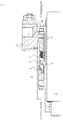
- FIG. 1 is a front cross-sectional view illustrating an example of a mechanical seal for general industrial machinery.
- the mechanical seal in FIG. 1 is of the inside type, which is a type for sealing in a sealed fluid attempting to leak out from an outer periphery of a sealing face toward the inner peripheral direction.
- An annular rotating ring 3, which is provided closer to a rotating shaft 1 for driving a pump impeller (not shown) on a sealed fluid side, with a sleeve 2 therebetween, in a state permitting rotation in an integral fashion with the rotating shaft 1; and a stationary ring 6 provided to a seal cover 5 fixed to a housing 4 of a pump in a non-rotating state and in a state permitting movement in the axial direction are made to slide in close contact on sealing faces S that have been mirror-finished using lapping or another technique, by a bellows 7 for urging the fixed ring 6 in the axial direction.
- the mechanical seal is intended to prevent the sealed fluid from flowing out from the outer periphery of the rotating shaft 1 toward the atmosphere side on sealing faces S of each of the rotating ring 3 and the fixed ring 6.
- the rotating ring 3 and the fixed ring 6 are typically formed from SiC (a hard material) or using a combination of SiC (a hard material) and carbon (a soft material), but sliding materials that are used for mechanical seals could also be applied.
- SiC includes a sintered compact for which boron, aluminum, carbon, or the like has been used as a sintering auxiliary, referring to materials comprising two or more types of phases of different ingredients or components, e.g., SiC having graphite particles dispersed therein, reaction-sintered SiC comprising SiC and Si, SiC-TiC, SiC-TiN, or the like.
- Carbon includes carbonaceous/graphitic carbon mixtures, for which it would be possible to use resin-molding carbon, sintered carbon, or the like. In addition to these sliding materials, it would also be possible to apply a metallic material, resin material, a surface-modified material (coating material), composite material, or the like.
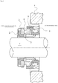
- FIG. 2 is a front cross-sectional view illustrating an example of a mechanical seal for a water pump.
- the mechanical seal in FIG. 2 is of the inside type, which is a type for sealing in cooling water attempting to leak out from an outer periphery of a sealing face toward the inner peripheral direction.
- An annular rotating ring 3, which is provided closer to a rotating shaft 1 for driving a pump impeller (not shown) on a cooling water side, interposed by a sleeve 2, in a state permitting rotation in an integral fashion with the rotating shaft 1; and a stationary ring 6 provided to a housing 4 of a pump in a non-rotating state and in a state permitting movement in the axial direction are made to slide in close contact on sealing faces S that have been mirror-finished using lapping or another technique, by a coiled wave spring 8 and a bellows 9 which urge the fixed ring 6 in the axial direction.
- the mechanical seal is intended to prevent the cooling water from flowing out from the outer periphery of the rotating shaft 1 toward the atmosphere side on the sealing faces S of each of the rotating ring 3 and the fixed ring 6.
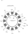
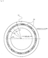
- FIG. 3 is a plan view illustrating a mechanical seal as in a first embodiment of the present invention, as exemplified in FIGS. 1 and 2 , wherein the first embodiment illustrates a case where sealed-fluid-accommodating blocks and pumping parts are formed on the sealing face S of the fixed ring 6, which, of the sealing faces of the fixed ring 6 and the rotating ring 3, has the lesser width in the radial direction.
- a plurality of sealed-fluid-accommodating blocks 10 separated in the circumferential direction are formed on the sealing face S of the fixed ring 6 so as to be a part of the sealing face S in the radial direction and to communicate directly to a sealed fluid accommodation space via an outer peripheral side 12.
- the sealed-fluid-accommodating blocks 10 may also be formed so as to be a part of the sealing face S in the radial direction and to communicate directly to the sealed fluid accommodation space via the inner peripheral side.
- the width a of the sealed-fluid-accommodating blocks 10 in the radial direction is set to be about one- to two-thirds of the width A of the sealing face S in the radial direction, and the angular range b of the sealed-fluid-accommodating blocks 10 in the peripheral direction is set to be equal to or slightly greater than an angular range B of the sealing face existing between adjacent sealed-fluid-accommodating blocks 10, 10.
- the plurality of sealed-fluid-accommodating blocks 10, which stand apart in the circumferential direction, are arranged on the sealing face S, and pumping parts 11 whereby a pumping action arises due to the relative rotation and sliding of the fixed ring 6 and the rotating ring 3 are formed on a bottom part of the plurality of sealed-fluid-accommodating blocks 10.
- the pumping parts 11 are provided with intake pumping part 11a which acts in a direction in which the sealed fluid is drawn in, and a discharge pumping part 11b which acts in a direction in which the sealed fluid is discharged.
- a plurality of linear irregularities (also called a "periodic structure of linear irregularities" in the present invention) at a constant pitch are formed in parallel with each other on each of the pumping parts 11; the irregularities are minute structures formed, for example, using a femtosecond laser.
- linear irregularity as used in the present invention comprises not only rectilinear irregularities but also slightly bent irregularities and curved irregularities which appear during a step for forming rectilinear irregularities.
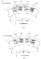
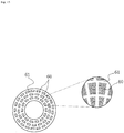
- FIG. 4 which describes the sealed-fluid-accommodating blocks and pumping parts in FIG. 3 , depicts the state during operation, where FIG. 4A is an enlarged plan view of the main parts and FIG. 4B is a cross-sectional view along the X-X line in FIG. 4A .
- the fixed ring 6 is indicated by a solid line
- the rotating ring 3 which is an opposing sliding member, is indicated by a double-dashed line; the rotating ring 3 rotates in the direction "R.”
- the plurality of sealed-fluid-accommodating blocks 10 are separated by the sealing face S from sealed-fluid-accommodating blocks 10 adjacent in the circumferential direction, and do not communicate with the atmosphere side due to the sealing face S.
- the sealed-fluid-accommodating blocks 10 are formed on a part of the sealing face S in the radial direction, make a convex shape so as to be able to accommodate the sealed fluid, have a step from the sealing face S, and communicate directly with the sealed fluid accommodation space via an outer peripheral side 12.
- the linear irregularities formed on the pumping parts 11 are formed so as to slope at a predetermined angle ⁇ (an angle formed by the tangent line in the case of curved irregularities; the same applies below) with respect to the sliding direction of the sealing face S; i.e., with respect to a rotational tangent line direction of the sealing face S.
- the predetermined angle ⁇ is preferably in the range of 10 to 80° in both the inner radial direction and outer radial direction with respect to the rotational tangent line of the sealing face S.
- the slope angle ⁇ of the linear irregularities of the pumping parts 11 with respect to the rotational tangent line in each of the plurality of sealed-fluid-accommodating blocks 10 may be the same for all or may be different for each pumping part 11.
- the sliding properties of the sealing face S are influenced in accordance with the slope angle ⁇ , it is more effective for the slope angle of the irregularities of each of the pumping parts 11 to be standardized overall depending on the desired lubrication performance or sliding conditions to a specific, appropriate slope angle ⁇ in order to yield stabilized sliding properties.
- the slope angle ⁇ of the irregularities with respect to the rotational tangent line in each of the plurality of pumping parts 11 is therefore restricted to a specific, optimal angle when the rotation and sliding direction of the sealing face S is unidirectional.
- first pumping parts which have irregularities that are sloped with respect to the rotational tangent line by a first angle whereby sliding properties become suitable during rotation in one direction
- second pumping parts which have irregularities that are sloped with respect to the rotational tangent line by a second angle whereby sliding properties become suitable during rotation in the direction inverse thereto.
- the irregularities of the intake pumping parts 11a and the discharge pumping parts 11b are preferably formed so that the respective slope angles ⁇ thereof will be angles that are symmetrical with respect to the rotational tangent line.
- the intake pumping parts 11a and the discharge pumping parts 11b are preferably formed so as to be arranged in alternation along the peripheral direction of the sealing face S.
- the sealing face S illustrated in FIGS. 1 and 2 is a preferred configuration of the sealing face S for a case where the sealing face S of such description is to rotate in two directions.
- the intake pumping parts 11a and the discharge pumping parts 11b may instead, for example, be arranged at a ratio of two intake pumping parts 11a for every one discharge pumping part 11b, or alternatively may be arranged at the inverse ratio.
- the pumping parts 11, which are a structure (a periodic structure of linear irregularities) where a plurality of linear irregularities at a constant pitch are precisely arranged at a predetermined pitch in parallel with each other, are formed by using, for example, a femtosecond laser to make exact sections in a predetermined region of the sealing face S and to precisely control the direction of the irregularities in each of the sections.
- interference between incident light and plasma waves or scattered light running along the surface of the substrate forms an irregular-shaped periodic structure having a pitch and groove depth on a wavelength order, in a self-organized fashion orthogonal to the direction of polarization.
- the associated periodic structure pattern can be formed on the surface by carrying out the operation while also overlapping the femtosecond laser.
- the directionality thereof can be controlled, and the processing positions can also be controlled, and thus discrete, small sections can be divided and a desired periodic structure can be formed in each of the sections. More specifically, when this method is used while the sealing face of an annular mechanical seal sliding member is caused to rotate, a fine periodic pattern can be selectively formed on the sealing face. Moreover, with a processing method that uses a femtosecond laser, it is possible to form irregularities on a sub-micron order, such irregularities being effective in enhancing the lubrication performance of the mechanical seal and in reducing leakage.
- the formation of the sealed-fluid-accommodating blocks 10 and the periodic structure of linear irregularities is not limited to a femtosecond laser; a picosecond laser or electron beam may also be used. Further, the formation of the sealed-fluid-accommodating blocks 10 and the periodic structure of linear irregularities may also be carried out by using a die provided with a periodic structure of linear irregularities to stamp or engrave while also causing the sealing face of the annular mechanical seal sliding member to rotate.
- etching may be carried out, followed by the formation of the period structure of linear irregularities on a bottom part of the sealed-fluid-accommodating blocks using a femtosecond laser or the like.
- a femtosecond laser may also be used to form only the periodic structure of linear irregularities on the sealing face, and thereafter the sealing face where the periodic structure of linear irregularities was not formed may be plated or have a film formed thereon to form the sealed-fluid-accommodating blocks 10.
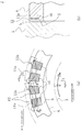
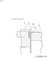
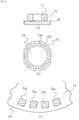
- FIG. 5 is a perspective view seen from the sealed fluid side, which depicts the sealed-fluid-accommodating blocks and pumping parts in FIGS. 3 and 4 .
- a liquid film that is 0.1 to 10 ⁇ m thick is formed between the sealing faces of the fixed ring 6 and the rotating ring 3, but in this case, if a virtual plane linking the vertices of the irregularities is drawn in the pumping parts 11, the virtual plane is set to be d1 (0.1h to 10h) lower than the sealing face S in accordance with the liquid film h, and the virtual plane is shaped to form a step d1 relative to the sealing face S.
- the sealed fluid is caught by the space within the sealed-fluid-accommodating blocks 10 formed by this step d1, and an adequate liquid film is formed.
- the pumping parts 11 from which a flow of liquid arises so as to prevent the sealed fluid from leaking out to the atmosphere side are formed on the bottom part of the sealed-fluid-accommodating blocks 10.
- the sealed-fluid-accommodating blocks 10 are formed first, after which the pumping parts 11 are formed.
- the depth d2 of the vertices and bottom parts of the irregularities is preferably such that d2 is 0.1h to 10h.
- the pitch p of the linear irregularities of the pumping parts 11 is set in accordance with the viscosity of the sealed fluid, but a range of 0.1-100 ⁇ m is preferable. In a case where the sealed fluid is highly viscous, it is better for the pitch p to be sized so as to allow the sealed fluid to adequate enter into the grooves.
- the pumping parts 11 have been formed in parallel with a plane orthogonal to the shaft in the circumferential direction and the radial direction.
- the sealed fluid will be caught in the sealed-fluid-accommodating blocks 10 provided with the intake pumping parts 11a, the sealed fluid will be sent in to the sealed-fluid-accommodating blocks 10 provided with the discharge pumping parts 11b located at positions separated by the sealing face S, and the sealed fluid will be returned to the sealed fluid side from the sealed-fluid-accommodating blocks 10 by the action of the discharge pumping parts 11b (see the arrow illustrated with a double-dashed line in FIG. 4A ).
- the lubrication performance of the sealing face S can be ensured, and leakage can be prevented and sealing performance maintained.
- FIG. 6 is a cross-sectional view illustrating the sealed-fluid-accommodating blocks 10 and pumping parts 11 formed on the sealing face S of the fixed ring 6 of the mechanical seal as in the second embodiment of the present invention, as exemplified in FIGS. 1 and 2 .
- the pumping parts 11 were formed to be parallel to a plane orthogonal to the shaft in the circumferential direction and the radial direction; however, in FIG. 6 , the intake pumping parts 11a formed on the bottom part of the sealed-fluid-accommodating blocks 10 are formed so that the linear irregularities thereof gradually become higher toward the direction R of rotation of the rotating ring 3, which is an opposing sliding member; the discharge pumping parts 11b are formed so that the linear irregularities thereof gradually become lower toward the direction R of rotation of the rotating ring 3, which is an opposing sliding member.
- the linear irregularities are also formed to be sloped in the peripheral direction when seen from a side view as well, and thus it is even further possible in the intake pumping parts 11a for the sealed fluid to be caught and sent to the discharge pumping parts 11b. It is even further possible in the discharge pumping parts 11b for the sealed fluid having been sent therein to be returned to the sealed fluid side.
- the depth of the deepest part and shallowest part of the virtual plane linking the vertices of the irregularities of the pumping parts, from the sealing face may be set to fall within the range 0.1h to 10h.
- the pumping parts 11 formed on the bottom part of the sealed-fluid-accommodating blocks 10 can be sloped as needed, in the circumferential direction and/or the radial direction.
- the intake pumping parts 11a being formed so as to gradually become lower toward the inside in the radial direction, will more readily take in the sealed fluid
- the discharge pumping parts 11b being formed so as to gradually become higher in toward the inside in the radial direction, will more readily discharge the sealed fluid.
- the depth of the deepest part and shallowest part of the virtual plane linking the vertices of the irregularities of the pumping parts, from the sealing face may be set to fall within the range 0.1h to 10h.
- FIG. 7 is a plan view illustrating a mechanical seal as in a third embodiment of the present invention, as exemplified in FIGS. 1 and 2 , wherein this embodiment is a case where the sealed-fluid-accommodating blocks and pumping parts are formed on the sealing face of the rotating ring, which, of the sealing faces of the fixed ring and the rotating ring, has the greater width in the radial direction.
- the plurality of sealed-fluid-accommodating blocks 10 separated in the circumferential direction are formed on the sealing face S of the rotating ring 3, which, of the sealing faces of the rotating ring 3 and the fixed ring 6, has the greater sealing face width in the radial direction.
- the plurality of sealed-fluid-accommodating blocks 10 are formed on a part of the sealing face S that does not include the radial outward and inward sides thereof, and are formed so that a part of the sealed fluid side of the sealed-fluid-accommodating blocks 10 is not covered by the opposing sealing face S of the fixed ring 6. For this reason, the sealing performance when stationary is maintained, and during start-up, the sealed fluid will be caught by the sealed-fluid-accommodating blocks 10.
- the sealed-fluid-accommodating blocks 10 may also be arranged so that a part of the sealed-fluid-accommodating blocks 10 on the inside in the radial direction is not covered by the opposing sealing face of the fixed ring 6.
- FIG. 8 is a plan view describing another example of the pumping parts as in the fourth embodiment of the present invention, and illustrates an exemplary case where the sealed-fluid-accommodating blocks and pumping parts are formed on the sealing face of the fixed ring, which, of the sealing faces of the fixed ring and the rotating ring, has the lesser width in the radial direction.
- the pitch Pb of the linear irregularities of the discharge pumping parts 11b is formed to be smaller than the pitch Pa of the linear irregularities of the intake pumping parts 11a, and the discharge capacity of the discharge pumping parts 11b is set to be greater than the intake capacity of the intake pumping parts 11a. For this reason, the sealed fluid flowing in from the intake pumping parts 11a and elsewhere will be discharged from the discharge pumping parts 11b to the sealed fluid side and is prevented from leaking out to the atmosphere side.
- the width or depth of the linear irregularities of the discharge pumping parts 11b is formed to be greater than the width or depth of the linear irregularities of the intake pumping parts 11a, and the discharge capacity of the discharge pumping parts 11b is set to be greater than the intake capacity of the intake pumping parts 11a. For this reason, the sealed fluid flowing in from the intake pumping parts 11a and elsewhere is returned to the sealed fluid side from the discharge pumping parts 11b and is prevented from leaking out to the atmosphere side.
- FIG. 9 is a plan view describing another example of the pumping parts as in the fifth embodiment of the present invention, and illustrates an exemplary case where the sealed-fluid-accommodating blocks and pumping parts are formed on the sealing face of the fixed ring, which, of the sealing faces of the fixed ring and the rotating ring, has the lesser width in the radial direction.
- the length a of the intake pumping parts 11a and the discharge pumping parts 11b in the peripheral direction is identical, but the length b' of the discharge pumping parts 11b in the radial direction is set to be greater than the length b of the intake pumping parts 11a in the radial direction, and the discharge capacity of the discharge pumping parts 11b is set to be greater than the intake capacity of the intake pumping parts 11a. For this reason, the sealed fluid flowing in from the intake pumping parts 11a and elsewhere is returned to the sealed fluid side from the discharge pumping parts 11b, and is prevented from leaking out to the atmosphere side.
- the length b of the intake pumping parts 11a and the discharge pumping parts 11b in the radial direction is identical, but the length a' of the discharge pumping parts 11b in the peripheral direction is formed to be greater than the length a of the intake pumping parts 11a in the peripheral direction, and the discharge capacity of the discharge pumping parts 11b is set to be greater than the intake capacity of the intake pumping parts 11a. For this reason, the sealed fluid flowing in from the intake pumping parts 11a and elsewhere is returned to the sealed fluid side from the discharge pumping parts 11b, and is prevented from leaking out to the atmosphere side.
- the length of the discharge pumping parts 11b in the peripheral direction or the length thereof in the radial direction may be formed to be greater than the length of the intake pumping parts 11a in the peripheral direction or greater than the length thereof in the radial direction, and the discharge capacity of the discharge pumping parts may be set to be greater than the intake capacity of the intake pumping parts 11a.
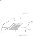
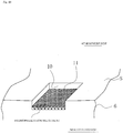
- FIG. 10 is a perspective view, seen from the sealed fluid side, depicting another example of the pumping parts as in the sixth embodiment of the present invention, and illustrates an exemplary case where the sealed-fluid-accommodating blocks and pumping parts are formed on the sealing face of the fixed ring, which, of the sealing faces of the fixed ring and the rotating ring, has the lesser width in the radial direction.
- the sealed fluid of the intake pumping parts 11a is less likely to be drawn in since the sealed-fluid-accommodating blocks 10 are extremely shallow. Also, since the gap of the sealing face S is narrow, the sealed fluid discharged from the intake pumping parts 11a will, when about to flow into the discharge pumping parts 11b, be less likely to do so. It is necessary for the sealed fluid to readily flow into the pumping parts 11 in order for the performance of the pumping parts 11 to be exhibited.
- a hydrophilization treatment is carried out along the surface of the irregularity parts of the pumping parts 11 (the intake pumping parts 11a and the discharge pumping parts 11b) formed on the bottom part of the sealed-fluid-accommodating blocks 10 and wettability is controlled as a remedial measure so that the sealed fluid will more readily flow into the pumping parts 11.
- the hatching indicating that the hydrophilization treatment has been carried out may appear to embed the recesses of the pumping parts 11, but is applied over the surface of the irregularity parts, the hydrophilization of the pumping parts 11 being carried out along the surface of the irregularity parts.
- Hydrophilization means include:
- Hydrophilic coating materials in the case of coating with a hydrophilic substance include silica, alumina, zirconia, titania, and other ceramics, or fatty acid esters, fatty acid ethers, sulfuric acid esters, phosphoric acid esters, sulfates, and other organic substances, as well as compounds having a hydrophilic group (a fatty acid, carboxylic acid residue, or the like) on the surface.
- the method of coating includes painting, a sol-gel method, plasma treatment, PVD, CVD, shot peening; it would also be possible to use a method that employs a photocatalyst.
- FIG. 11 illustrates an example of a case where the sealed-fluid-accommodating blocks and pumping parts are formed on the sealing face of the fixed ring, which, of the sealing faces of the fixed ring and the rotating ring, has the lesser width in the radial direction.
- An annular water-repellent coating 16 is provided to the sliding part on the atmosphere side of the sealing face S.
- FIG. 11 illustrates a case where the hydrophilic coating 15 illustrated in the sixth embodiment is provided to the pumping parts 11 (to the intake pumping parts 11a and the discharge pumping parts 11b); however, this is not necessarily required, it being readily apparent that the water-repellent coating 16 may also be provided alone.
- the intake pumping parts 11a and the discharge pumping parts 11b are hydrophilic, the introduction of sealed fluid is promoted, and the lubrication performance of the sealing face S is improved.
- the sealed fluid is prevented from leaking to the atmosphere side, since the sliding part on the atmosphere side is water-repellent.
- FIG. 12 illustrates a variety of examples of water-repellent coatings for the case where the sealed-fluid-accommodating blocks and pumping parts are formed on the sealing face of the fixed ring, which, of the sealing faces of the fixed ring and the rotating ring, has the lesser width in the radial direction.
- the hydrophilic coating 15 is provided to the pumping parts 11, and an annular water-repellent coating 16 is provided to the sliding part on the atmosphere side of the sealing face S to which the pumping parts 11 are provided.
- a step corresponding to the thickness of the water-repellent coating 16 is formed on the sealing face where the water-repelling coating 16 is provided, but there is no impact on sealing performance provided that the thickness of the water-repellent coating 16 is about the thickness of the liquid film of the sealing face S.
- FIG. 12B an annular recess from which an amount equivalent to the thickness of the water-repellent coating 16 has been removed is formed on the sliding part on the atmosphere side of the sealing face S where the pumping parts 11 are provided, and the water-repellent coating 16 is provided to the annular recess. For this reason, the sealing face is flush and has no step.
- FIG. 12C an annular recess from which an amount equal to or greater than the thickness of the water-repellent coating 16 has been removed is formed on the sliding part on the atmosphere side of the sealing face S where the pumping parts 11 are provided, and the water-repellent coating 16 is provided to the annular recess.
- the water-repellent coating 16 will not be in contact with the opposing sliding member, but leakage of the sliding fluid can still be adequately prevented provided that there is a gap no greater than 1 ⁇ m.
- annular recesses from which an amount equivalent to the thickness of the water-repellent coating 16 has been removed are formed on the sliding parts on the atmosphere side of each of the sealing faces S, and the water-repellent coating 16 is provided to the annular recesses. In this case, leakage of the sealed fluid to the atmosphere side is even further prevented.
- FIG. 13 illustrates a variety of examples of the water-repellent coating in the case where the sealed-fluid-accommodating blocks and pumping parts are formed on the sealing face of the rotating ring, which, of the sealing faces of the fixed ring and the rotating ring, has the greater width in the radial direction.
- the hydrophilic coating 15 is provided to the pumping parts 11, and the annular water-repellent coating 16 is provided to the sliding part on the atmosphere side of the sealing face S, to which the pumping parts 11 are provided.
- a step in the amount of the thickness of the water-repellent coating 16 is formed on the sealing face where the water-repelling coating 16 is provided, but there is no impact on sealing performance provided that the thickness of the water-repellent coating 16 is about the thickness of the liquid film of the sealing face S.
- FIG. 13B an annular recess from which an amount equivalent to the thickness of the water-repellent coating 16 has been removed is formed on the sliding part on the atmosphere side of the sealing face S where the pumping parts 11 are provided, and the water-repellent coating 16 is provided to the annular recess. For this reason, the sealing face is flush and has no step.
- FIG. 13C an annular recess from which an amount equal to or greater than the thickness of the water-repellent coating 16 has been removed is formed on the sliding part on the atmosphere side of the sealing face S where the pumping parts 11 are provided, and the water-repellent coating 16 is provided to the annular recess.
- the water-repellent coating 16 will not be in contact with the opposing sliding member, but leakage of the sliding fluid can still be adequately prevented provided that there is a gap no greater than 1 ⁇ m.
- annular recesses from which an amount equivalent to the thickness of the water-repellent coating 16 has been removed are formed on the sliding parts on the atmosphere side of each of the sealing faces S, and the water-repellent coating 16 is provided to the annular recesses. In this case, leakage of the sealed fluid to the atmosphere side is even further prevented.
- the fourth and fifth embodiments describe cases where the pumping capacity of the discharge pumping parts is greater than the pumping capacity of the intake pumping parts in the pumping parts formed on the bottom part of the plurality of sealed-fluid-accommodating blocks, but depending on the mode for using the mechanical seal, there are some cases where a certain amount of leakage is acceptable. In such cases, lubrication may be emphasized and the pumping capacity of the intake pumping parts may also be set greater than the pumping capacity of the discharge pumping parts.
Landscapes
- Engineering & Computer Science (AREA)
- General Engineering & Computer Science (AREA)
- Mechanical Engineering (AREA)
- Mechanical Sealing (AREA)
Applications Claiming Priority (2)
| Application Number | Priority Date | Filing Date | Title |
|---|---|---|---|
| JP2011171414 | 2011-08-05 | ||
| PCT/JP2012/069144 WO2013021839A1 (ja) | 2011-08-05 | 2012-07-27 | メカニカルシール |
Publications (3)
| Publication Number | Publication Date |
|---|---|
| EP2740974A1 EP2740974A1 (en) | 2014-06-11 |
| EP2740974A4 EP2740974A4 (en) | 2015-07-08 |
| EP2740974B1 true EP2740974B1 (en) | 2018-04-18 |
Family
ID=47668352
Family Applications (1)
| Application Number | Title | Priority Date | Filing Date |
|---|---|---|---|
| EP12821851.8A Active EP2740974B1 (en) | 2011-08-05 | 2012-07-27 | Mechanical seal |
Country Status (6)
| Country | Link |
|---|---|
| US (1) | US9982784B2 (ja) |
| EP (1) | EP2740974B1 (ja) |
| JP (3) | JP5936079B2 (ja) |
| KR (1) | KR101513278B1 (ja) |
| CN (1) | CN103620277B (ja) |
| WO (1) | WO2013021839A1 (ja) |
Families Citing this family (26)
| Publication number | Priority date | Publication date | Assignee | Title |
|---|---|---|---|---|
| JP5758378B2 (ja) * | 2010-03-15 | 2015-08-05 | イーグル工業株式会社 | 摺動部材 |
| CN103732956B (zh) * | 2011-09-06 | 2016-03-30 | 伊格尔工业股份有限公司 | 轴封装置 |
| US9234594B2 (en) * | 2012-05-21 | 2016-01-12 | Eagle Industry Co., Ltd. | Sliding component |
| CN104321568B (zh) * | 2012-09-11 | 2017-02-22 | 伊格尔工业股份有限公司 | 滑动部件 |
| EP2853789B1 (en) * | 2012-10-18 | 2019-03-06 | Eagle Industry Co., Ltd. | Slide part |
| JP6168615B2 (ja) * | 2012-11-28 | 2017-08-02 | 国立大学法人 熊本大学 | 軸封装置及びシール部材並びに水力発電装置 |
| EP3190317B1 (en) * | 2014-09-04 | 2022-02-09 | Eagle Industry Co., Ltd. | Mechanical seal |
| WO2016037652A1 (en) * | 2014-09-11 | 2016-03-17 | Aktiebolaget Skf | Dynamic seal |
| US9682441B2 (en) | 2015-06-01 | 2017-06-20 | Caterpillar Inc. | Laser polishing system and method for metal face seal |
| WO2017002774A1 (ja) * | 2015-06-30 | 2017-01-05 | イーグル工業株式会社 | シール装置 |
| JPWO2017010146A1 (ja) * | 2015-07-10 | 2018-04-19 | 株式会社荏原製作所 | 非接触環状シール及びこれを備える回転機械 |
| CN106313926B (zh) * | 2016-09-27 | 2019-01-29 | 清华大学 | 一种改变浸渍石墨表面浸润性能的表面改性方法 |
| EP3617565A4 (en) * | 2017-04-25 | 2020-12-30 | NOK Corporation | WATERPROOFING ELEMENT |
| EP3653913A4 (en) * | 2017-07-13 | 2021-03-17 | Eagle Industry Co., Ltd. | SLIDING ELEMENT |
| EP3693638A4 (en) | 2017-10-03 | 2021-06-23 | Eagle Industry Co., Ltd. | SLIDING COMPONENT |
| US11608897B2 (en) | 2018-08-01 | 2023-03-21 | Eagle Industry Co., Ltd. | Slide component |
| WO2020040234A1 (ja) | 2018-08-24 | 2020-02-27 | イーグル工業株式会社 | 摺動部材 |
| US11815184B2 (en) | 2018-11-30 | 2023-11-14 | Eagle Industry Co., Ltd. | Sliding component |
| CN109488769B (zh) * | 2018-12-20 | 2024-01-16 | 丹东克隆集团有限责任公司 | 带双向螺旋泵送环封液循环机构的双端面机械密封 |
| WO2020130087A1 (ja) | 2018-12-21 | 2020-06-25 | イーグル工業株式会社 | 摺動部品 |
| JP7370681B2 (ja) | 2019-02-14 | 2023-10-30 | イーグル工業株式会社 | 摺動部品 |
| US20220099138A1 (en) * | 2019-02-21 | 2022-03-31 | Eagle Industry Co., Ltd. | Sliding components |
| US20220145931A1 (en) * | 2019-04-09 | 2022-05-12 | Eagle Industry Co., Ltd. | Sliding component |
| EP4345342A2 (en) | 2019-07-26 | 2024-04-03 | Eagle Industry Co., Ltd. | Sliding component |
| US20230027772A1 (en) * | 2019-12-17 | 2023-01-26 | Eagle Industry Co., Ltd. | Sliding component |
| WO2024043211A1 (ja) * | 2022-08-23 | 2024-02-29 | イーグル工業株式会社 | メカニカルシール |
Family Cites Families (28)
| Publication number | Priority date | Publication date | Assignee | Title |
|---|---|---|---|---|
| US3499653A (en) * | 1968-06-05 | 1970-03-10 | Crane Packing Co | Rotary mechanical seal of the gap type |
| US5312117A (en) * | 1977-04-12 | 1994-05-17 | Taiho Kogyo Co., Ltd. | Mechanical seal |
| JPS57161366A (en) * | 1981-03-31 | 1982-10-04 | Eagle Ind Co Ltd | Mechanical seal |
| JPS61184165U (ja) | 1985-05-09 | 1986-11-17 | ||
| JPH0128374Y2 (ja) * | 1985-06-03 | 1989-08-29 | ||
| JPS63118460U (ja) | 1987-01-27 | 1988-07-30 | ||
| JPH01158270A (ja) * | 1987-12-15 | 1989-06-21 | Mayekawa Mfg Co Ltd | メカニカルシール |
| JPH0614148Y2 (ja) | 1988-03-08 | 1994-04-13 | イーグル工業株式会社 | ドライ摺動型メカニカルシール |
| JPH0660691B2 (ja) * | 1990-04-17 | 1994-08-10 | イーグル工業株式会社 | 両回転式準接触メカニカルシール及びリング摺動面の溝加工方法 |
| GB9103217D0 (en) * | 1991-02-15 | 1991-04-03 | Crane John Uk Ltd | Mechanical face seals |
| DE4209484A1 (de) * | 1991-06-12 | 1993-10-21 | Heinz Konrad Prof Dr I Mueller | Gleitringdichtung mit Rückförderwirkung |
| JPH0590050U (ja) * | 1992-02-06 | 1993-12-07 | イーグル工業株式会社 | 両方向回転型ガスシール |
| US5533739A (en) * | 1992-06-10 | 1996-07-09 | Durametallic Corporation | Non-contacting seal with centering spring mounted in dovetailed grooved |
| US5501470A (en) * | 1992-12-11 | 1996-03-26 | Nippon Pillar Packing Co., Ltd. | Non-contacting shaft sealing device with grooved face pattern |
| JP2639883B2 (ja) * | 1993-07-22 | 1997-08-13 | 日本ピラー工業株式会社 | 非接触形軸封装置 |
| JP2563081B2 (ja) * | 1994-03-22 | 1996-12-11 | 日本ピラー工業株式会社 | 非接触形軸封装置 |
| JPH09329247A (ja) * | 1996-06-11 | 1997-12-22 | Ebara Corp | 非接触端面シール |
| PL187630B1 (pl) * | 1998-12-10 | 2004-08-31 | Anga Uszczelnienia Mechaniczne | Pierścień ślizgowy uszczelnienia mechanicznego czołowego bezstykowego |
| US6446976B1 (en) * | 2000-09-06 | 2002-09-10 | Flowserve Management Company | Hydrodynamic face seal with grooved sealing dam for zero-leakage |
| JP2004183810A (ja) | 2002-12-04 | 2004-07-02 | Matsushita Electric Ind Co Ltd | ウォーターポンプ用メカニカルシール |
| JP2005121164A (ja) * | 2003-10-17 | 2005-05-12 | Nsk Ltd | シール装置 |
| JP2005188651A (ja) * | 2003-12-25 | 2005-07-14 | Yamada Seisakusho Co Ltd | ウォーターポンプにおけるメカニカルシール |
| KR100965978B1 (ko) * | 2004-08-27 | 2010-06-24 | 한국씰마스타주식회사 | 미케니컬 페이스 씰의 그루브패턴구조 |
| JP4263185B2 (ja) | 2005-09-06 | 2009-05-13 | キヤノンマシナリー株式会社 | 低摩擦しゅう動面 |
| JP4699946B2 (ja) * | 2006-06-09 | 2011-06-15 | イーグル工業株式会社 | メカニカルシール装置 |
| JP5111961B2 (ja) * | 2007-07-09 | 2013-01-09 | キヤノンマシナリー株式会社 | 摺動面構造 |
| US8360436B2 (en) * | 2008-01-11 | 2013-01-29 | Eagle Industry Co., Ltd. | Mechanical seal sliding member, and mechanical seal |
| JP2009250378A (ja) | 2008-04-08 | 2009-10-29 | Eagle Ind Co Ltd | 液体用のメカニカルシール装置 |
-
2012
- 2012-07-27 WO PCT/JP2012/069144 patent/WO2013021839A1/ja active Application Filing
- 2012-07-27 EP EP12821851.8A patent/EP2740974B1/en active Active
- 2012-07-27 CN CN201280031364.5A patent/CN103620277B/zh active Active
- 2012-07-27 KR KR1020137030778A patent/KR101513278B1/ko active IP Right Grant
- 2012-07-27 US US14/234,200 patent/US9982784B2/en active Active
- 2012-07-27 JP JP2013527961A patent/JP5936079B2/ja active Active
-
2015
- 2015-08-07 JP JP2015156967A patent/JP2016028210A/ja active Pending
- 2015-09-24 JP JP2015187040A patent/JP5980396B2/ja active Active
Non-Patent Citations (1)
| Title |
|---|
| None * |
Also Published As
| Publication number | Publication date |
|---|---|
| JP2016028210A (ja) | 2016-02-25 |
| KR20130140209A (ko) | 2013-12-23 |
| CN103620277A (zh) | 2014-03-05 |
| JP2016014482A (ja) | 2016-01-28 |
| JPWO2013021839A1 (ja) | 2015-03-05 |
| KR101513278B1 (ko) | 2015-04-17 |
| JP5936079B2 (ja) | 2016-06-15 |
| EP2740974A1 (en) | 2014-06-11 |
| US20140167361A1 (en) | 2014-06-19 |
| CN103620277B (zh) | 2016-08-17 |
| EP2740974A4 (en) | 2015-07-08 |
| JP5980396B2 (ja) | 2016-08-31 |
| WO2013021839A1 (ja) | 2013-02-14 |
| US9982784B2 (en) | 2018-05-29 |
Similar Documents
| Publication | Publication Date | Title |
|---|---|---|
| EP2740974B1 (en) | Mechanical seal | |
| EP2752603B1 (en) | Sliding component | |
| JP7179430B2 (ja) | 摺動部品 | |
| JP5968889B2 (ja) | 摺動部品 | |
| CN109906330B (zh) | 滑动部件 | |
| EP3190317B1 (en) | Mechanical seal | |
| EP3091258B1 (en) | Sliding component | |
| JP5980217B2 (ja) | 軸封装置及びその製造方法 | |
| EP3258145A1 (en) | Sliding component | |
| US20220106980A1 (en) | Sliding components | |
| WO2008013147A1 (fr) | Dispositif d'etanchéité mécanique | |
| JP5950998B2 (ja) | 軸封装置 | |
| EP3051188B1 (en) | Sliding component | |
| US20240151309A1 (en) | Sliding component | |
| KR20130127591A (ko) | 소형 멀티스프링이 적용된 펌프용 메카니컬 씰 장치 |
Legal Events
| Date | Code | Title | Description |
|---|---|---|---|
| PUAI | Public reference made under article 153(3) epc to a published international application that has entered the european phase |
Free format text: ORIGINAL CODE: 0009012 |
|
| 17P | Request for examination filed |
Effective date: 20140210 |
|
| AK | Designated contracting states |
Kind code of ref document: A1 Designated state(s): AL AT BE BG CH CY CZ DE DK EE ES FI FR GB GR HR HU IE IS IT LI LT LU LV MC MK MT NL NO PL PT RO RS SE SI SK SM TR |
|
| DAX | Request for extension of the european patent (deleted) | ||
| RA4 | Supplementary search report drawn up and despatched (corrected) |
Effective date: 20150608 |
|
| RIC1 | Information provided on ipc code assigned before grant |
Ipc: F16J 15/34 20060101AFI20150601BHEP |
|
| STAA | Information on the status of an ep patent application or granted ep patent |
Free format text: STATUS: EXAMINATION IS IN PROGRESS |
|
| 17Q | First examination report despatched |
Effective date: 20161116 |
|
| GRAP | Despatch of communication of intention to grant a patent |
Free format text: ORIGINAL CODE: EPIDOSNIGR1 |
|
| STAA | Information on the status of an ep patent application or granted ep patent |
Free format text: STATUS: GRANT OF PATENT IS INTENDED |
|
| INTG | Intention to grant announced |
Effective date: 20171106 |
|
| GRAS | Grant fee paid |
Free format text: ORIGINAL CODE: EPIDOSNIGR3 |
|
| GRAA | (expected) grant |
Free format text: ORIGINAL CODE: 0009210 |
|
| STAA | Information on the status of an ep patent application or granted ep patent |
Free format text: STATUS: THE PATENT HAS BEEN GRANTED |
|
| AK | Designated contracting states |
Kind code of ref document: B1 Designated state(s): AL AT BE BG CH CY CZ DE DK EE ES FI FR GB GR HR HU IE IS IT LI LT LU LV MC MK MT NL NO PL PT RO RS SE SI SK SM TR |
|
| REG | Reference to a national code |
Ref country code: GB Ref legal event code: FG4D |
|
| REG | Reference to a national code |
Ref country code: CH Ref legal event code: EP |
|
| REG | Reference to a national code |
Ref country code: AT Ref legal event code: REF Ref document number: 990860 Country of ref document: AT Kind code of ref document: T Effective date: 20180515 |
|
| REG | Reference to a national code |
Ref country code: IE Ref legal event code: FG4D |
|
| REG | Reference to a national code |
Ref country code: DE Ref legal event code: R096 Ref document number: 602012045420 Country of ref document: DE |
|
| REG | Reference to a national code |
Ref country code: FR Ref legal event code: PLFP Year of fee payment: 7 |
|
| REG | Reference to a national code |
Ref country code: NL Ref legal event code: MP Effective date: 20180418 |
|
| REG | Reference to a national code |
Ref country code: LT Ref legal event code: MG4D |
|
| PG25 | Lapsed in a contracting state [announced via postgrant information from national office to epo] |
Ref country code: NL Free format text: LAPSE BECAUSE OF FAILURE TO SUBMIT A TRANSLATION OF THE DESCRIPTION OR TO PAY THE FEE WITHIN THE PRESCRIBED TIME-LIMIT Effective date: 20180418 |
|
| PG25 | Lapsed in a contracting state [announced via postgrant information from national office to epo] |
Ref country code: FI Free format text: LAPSE BECAUSE OF FAILURE TO SUBMIT A TRANSLATION OF THE DESCRIPTION OR TO PAY THE FEE WITHIN THE PRESCRIBED TIME-LIMIT Effective date: 20180418 Ref country code: NO Free format text: LAPSE BECAUSE OF FAILURE TO SUBMIT A TRANSLATION OF THE DESCRIPTION OR TO PAY THE FEE WITHIN THE PRESCRIBED TIME-LIMIT Effective date: 20180718 Ref country code: BG Free format text: LAPSE BECAUSE OF FAILURE TO SUBMIT A TRANSLATION OF THE DESCRIPTION OR TO PAY THE FEE WITHIN THE PRESCRIBED TIME-LIMIT Effective date: 20180718 Ref country code: SE Free format text: LAPSE BECAUSE OF FAILURE TO SUBMIT A TRANSLATION OF THE DESCRIPTION OR TO PAY THE FEE WITHIN THE PRESCRIBED TIME-LIMIT Effective date: 20180418 Ref country code: AL Free format text: LAPSE BECAUSE OF FAILURE TO SUBMIT A TRANSLATION OF THE DESCRIPTION OR TO PAY THE FEE WITHIN THE PRESCRIBED TIME-LIMIT Effective date: 20180418 Ref country code: LT Free format text: LAPSE BECAUSE OF FAILURE TO SUBMIT A TRANSLATION OF THE DESCRIPTION OR TO PAY THE FEE WITHIN THE PRESCRIBED TIME-LIMIT Effective date: 20180418 Ref country code: PL Free format text: LAPSE BECAUSE OF FAILURE TO SUBMIT A TRANSLATION OF THE DESCRIPTION OR TO PAY THE FEE WITHIN THE PRESCRIBED TIME-LIMIT Effective date: 20180418 Ref country code: ES Free format text: LAPSE BECAUSE OF FAILURE TO SUBMIT A TRANSLATION OF THE DESCRIPTION OR TO PAY THE FEE WITHIN THE PRESCRIBED TIME-LIMIT Effective date: 20180418 |
|
| PG25 | Lapsed in a contracting state [announced via postgrant information from national office to epo] |
Ref country code: RS Free format text: LAPSE BECAUSE OF FAILURE TO SUBMIT A TRANSLATION OF THE DESCRIPTION OR TO PAY THE FEE WITHIN THE PRESCRIBED TIME-LIMIT Effective date: 20180418 Ref country code: GR Free format text: LAPSE BECAUSE OF FAILURE TO SUBMIT A TRANSLATION OF THE DESCRIPTION OR TO PAY THE FEE WITHIN THE PRESCRIBED TIME-LIMIT Effective date: 20180719 Ref country code: HR Free format text: LAPSE BECAUSE OF FAILURE TO SUBMIT A TRANSLATION OF THE DESCRIPTION OR TO PAY THE FEE WITHIN THE PRESCRIBED TIME-LIMIT Effective date: 20180418 Ref country code: LV Free format text: LAPSE BECAUSE OF FAILURE TO SUBMIT A TRANSLATION OF THE DESCRIPTION OR TO PAY THE FEE WITHIN THE PRESCRIBED TIME-LIMIT Effective date: 20180418 |
|
| REG | Reference to a national code |
Ref country code: AT Ref legal event code: MK05 Ref document number: 990860 Country of ref document: AT Kind code of ref document: T Effective date: 20180418 |
|
| PG25 | Lapsed in a contracting state [announced via postgrant information from national office to epo] |
Ref country code: PT Free format text: LAPSE BECAUSE OF FAILURE TO SUBMIT A TRANSLATION OF THE DESCRIPTION OR TO PAY THE FEE WITHIN THE PRESCRIBED TIME-LIMIT Effective date: 20180820 |
|
| REG | Reference to a national code |
Ref country code: DE Ref legal event code: R097 Ref document number: 602012045420 Country of ref document: DE |
|
| PG25 | Lapsed in a contracting state [announced via postgrant information from national office to epo] |
Ref country code: SK Free format text: LAPSE BECAUSE OF FAILURE TO SUBMIT A TRANSLATION OF THE DESCRIPTION OR TO PAY THE FEE WITHIN THE PRESCRIBED TIME-LIMIT Effective date: 20180418 Ref country code: RO Free format text: LAPSE BECAUSE OF FAILURE TO SUBMIT A TRANSLATION OF THE DESCRIPTION OR TO PAY THE FEE WITHIN THE PRESCRIBED TIME-LIMIT Effective date: 20180418 Ref country code: CZ Free format text: LAPSE BECAUSE OF FAILURE TO SUBMIT A TRANSLATION OF THE DESCRIPTION OR TO PAY THE FEE WITHIN THE PRESCRIBED TIME-LIMIT Effective date: 20180418 Ref country code: DK Free format text: LAPSE BECAUSE OF FAILURE TO SUBMIT A TRANSLATION OF THE DESCRIPTION OR TO PAY THE FEE WITHIN THE PRESCRIBED TIME-LIMIT Effective date: 20180418 Ref country code: AT Free format text: LAPSE BECAUSE OF FAILURE TO SUBMIT A TRANSLATION OF THE DESCRIPTION OR TO PAY THE FEE WITHIN THE PRESCRIBED TIME-LIMIT Effective date: 20180418 Ref country code: EE Free format text: LAPSE BECAUSE OF FAILURE TO SUBMIT A TRANSLATION OF THE DESCRIPTION OR TO PAY THE FEE WITHIN THE PRESCRIBED TIME-LIMIT Effective date: 20180418 |
|
| PLBE | No opposition filed within time limit |
Free format text: ORIGINAL CODE: 0009261 |
|
| STAA | Information on the status of an ep patent application or granted ep patent |
Free format text: STATUS: NO OPPOSITION FILED WITHIN TIME LIMIT |
|
| PG25 | Lapsed in a contracting state [announced via postgrant information from national office to epo] |
Ref country code: SM Free format text: LAPSE BECAUSE OF FAILURE TO SUBMIT A TRANSLATION OF THE DESCRIPTION OR TO PAY THE FEE WITHIN THE PRESCRIBED TIME-LIMIT Effective date: 20180418 |
|
| REG | Reference to a national code |
Ref country code: CH Ref legal event code: PL |
|
| 26N | No opposition filed |
Effective date: 20190121 |
|
| GBPC | Gb: european patent ceased through non-payment of renewal fee |
Effective date: 20180727 |
|
| PG25 | Lapsed in a contracting state [announced via postgrant information from national office to epo] |
Ref country code: LU Free format text: LAPSE BECAUSE OF NON-PAYMENT OF DUE FEES Effective date: 20180727 Ref country code: MC Free format text: LAPSE BECAUSE OF FAILURE TO SUBMIT A TRANSLATION OF THE DESCRIPTION OR TO PAY THE FEE WITHIN THE PRESCRIBED TIME-LIMIT Effective date: 20180418 |
|
| REG | Reference to a national code |
Ref country code: BE Ref legal event code: MM Effective date: 20180731 |
|
| PG25 | Lapsed in a contracting state [announced via postgrant information from national office to epo] |
Ref country code: GB Free format text: LAPSE BECAUSE OF NON-PAYMENT OF DUE FEES Effective date: 20180727 Ref country code: LI Free format text: LAPSE BECAUSE OF NON-PAYMENT OF DUE FEES Effective date: 20180731 Ref country code: CH Free format text: LAPSE BECAUSE OF NON-PAYMENT OF DUE FEES Effective date: 20180731 |
|
| REG | Reference to a national code |
Ref country code: IE Ref legal event code: MM4A |
|
| PG25 | Lapsed in a contracting state [announced via postgrant information from national office to epo] |
Ref country code: SI Free format text: LAPSE BECAUSE OF FAILURE TO SUBMIT A TRANSLATION OF THE DESCRIPTION OR TO PAY THE FEE WITHIN THE PRESCRIBED TIME-LIMIT Effective date: 20180418 Ref country code: BE Free format text: LAPSE BECAUSE OF NON-PAYMENT OF DUE FEES Effective date: 20180731 |
|
| PG25 | Lapsed in a contracting state [announced via postgrant information from national office to epo] |
Ref country code: IE Free format text: LAPSE BECAUSE OF NON-PAYMENT OF DUE FEES Effective date: 20180727 |
|
| PG25 | Lapsed in a contracting state [announced via postgrant information from national office to epo] |
Ref country code: MT Free format text: LAPSE BECAUSE OF NON-PAYMENT OF DUE FEES Effective date: 20180727 |
|
| PG25 | Lapsed in a contracting state [announced via postgrant information from national office to epo] |
Ref country code: TR Free format text: LAPSE BECAUSE OF FAILURE TO SUBMIT A TRANSLATION OF THE DESCRIPTION OR TO PAY THE FEE WITHIN THE PRESCRIBED TIME-LIMIT Effective date: 20180418 |
|
| PG25 | Lapsed in a contracting state [announced via postgrant information from national office to epo] |
Ref country code: HU Free format text: LAPSE BECAUSE OF FAILURE TO SUBMIT A TRANSLATION OF THE DESCRIPTION OR TO PAY THE FEE WITHIN THE PRESCRIBED TIME-LIMIT; INVALID AB INITIO Effective date: 20120727 |
|
| PG25 | Lapsed in a contracting state [announced via postgrant information from national office to epo] |
Ref country code: CY Free format text: LAPSE BECAUSE OF FAILURE TO SUBMIT A TRANSLATION OF THE DESCRIPTION OR TO PAY THE FEE WITHIN THE PRESCRIBED TIME-LIMIT Effective date: 20180418 Ref country code: MK Free format text: LAPSE BECAUSE OF NON-PAYMENT OF DUE FEES Effective date: 20180418 |
|
| PG25 | Lapsed in a contracting state [announced via postgrant information from national office to epo] |
Ref country code: IS Free format text: LAPSE BECAUSE OF FAILURE TO SUBMIT A TRANSLATION OF THE DESCRIPTION OR TO PAY THE FEE WITHIN THE PRESCRIBED TIME-LIMIT Effective date: 20180818 |
|
| PGFP | Annual fee paid to national office [announced via postgrant information from national office to epo] |
Ref country code: IT Payment date: 20230612 Year of fee payment: 12 Ref country code: FR Payment date: 20230620 Year of fee payment: 12 |
|
| PGFP | Annual fee paid to national office [announced via postgrant information from national office to epo] |
Ref country code: DE Payment date: 20230531 Year of fee payment: 12 |