EP4345342A2 - Sliding component - Google Patents
Sliding component Download PDFInfo
- Publication number
- EP4345342A2 EP4345342A2 EP24157861.6A EP24157861A EP4345342A2 EP 4345342 A2 EP4345342 A2 EP 4345342A2 EP 24157861 A EP24157861 A EP 24157861A EP 4345342 A2 EP4345342 A2 EP 4345342A2
- Authority
- EP
- European Patent Office
- Prior art keywords
- sliding
- groove
- sealed fluid
- seal ring
- annular groove
- Prior art date
- Legal status (The legal status is an assumption and is not a legal conclusion. Google has not performed a legal analysis and makes no representation as to the accuracy of the status listed.)
- Pending
Links
- 239000012530 fluid Substances 0.000 claims abstract description 71
- 230000002093 peripheral effect Effects 0.000 claims description 2
- 238000011084 recovery Methods 0.000 abstract description 8
- 239000000463 material Substances 0.000 description 9
- OKTJSMMVPCPJKN-UHFFFAOYSA-N Carbon Chemical compound [C] OKTJSMMVPCPJKN-UHFFFAOYSA-N 0.000 description 8
- 229910052799 carbon Inorganic materials 0.000 description 6
- 238000007789 sealing Methods 0.000 description 3
- 238000011144 upstream manufacturing Methods 0.000 description 3
- 230000001154 acute effect Effects 0.000 description 2
- 229910002804 graphite Inorganic materials 0.000 description 2
- 239000010439 graphite Substances 0.000 description 2
- 239000007788 liquid Substances 0.000 description 2
- 238000005461 lubrication Methods 0.000 description 2
- 239000000203 mixture Substances 0.000 description 2
- 238000012986 modification Methods 0.000 description 2
- 230000004048 modification Effects 0.000 description 2
- ZOXJGFHDIHLPTG-UHFFFAOYSA-N Boron Chemical compound [B] ZOXJGFHDIHLPTG-UHFFFAOYSA-N 0.000 description 1
- 238000007792 addition Methods 0.000 description 1
- 229910052782 aluminium Inorganic materials 0.000 description 1
- XAGFODPZIPBFFR-UHFFFAOYSA-N aluminium Chemical compound [Al] XAGFODPZIPBFFR-UHFFFAOYSA-N 0.000 description 1
- 230000015572 biosynthetic process Effects 0.000 description 1
- 229910052796 boron Inorganic materials 0.000 description 1
- 239000011248 coating agent Substances 0.000 description 1
- 238000000576 coating method Methods 0.000 description 1
- 239000002131 composite material Substances 0.000 description 1
- 230000000694 effects Effects 0.000 description 1
- 230000007613 environmental effect Effects 0.000 description 1
- 239000007769 metal material Substances 0.000 description 1
- 239000002245 particle Substances 0.000 description 1
- 239000011347 resin Substances 0.000 description 1
- 229920005989 resin Polymers 0.000 description 1
- 238000000926 separation method Methods 0.000 description 1
- 238000005245 sintering Methods 0.000 description 1
- 239000007779 soft material Substances 0.000 description 1
- 239000007787 solid Substances 0.000 description 1
Images


Classifications
-
- F—MECHANICAL ENGINEERING; LIGHTING; HEATING; WEAPONS; BLASTING
- F16—ENGINEERING ELEMENTS AND UNITS; GENERAL MEASURES FOR PRODUCING AND MAINTAINING EFFECTIVE FUNCTIONING OF MACHINES OR INSTALLATIONS; THERMAL INSULATION IN GENERAL
- F16J—PISTONS; CYLINDERS; SEALINGS
- F16J15/00—Sealings
- F16J15/16—Sealings between relatively-moving surfaces
- F16J15/34—Sealings between relatively-moving surfaces with slip-ring pressed against a more or less radial face on one member
- F16J15/3404—Sealings between relatively-moving surfaces with slip-ring pressed against a more or less radial face on one member and characterised by parts or details relating to lubrication, cooling or venting of the seal
- F16J15/3408—Sealings between relatively-moving surfaces with slip-ring pressed against a more or less radial face on one member and characterised by parts or details relating to lubrication, cooling or venting of the seal at least one ring having an uneven slipping surface
- F16J15/3412—Sealings between relatively-moving surfaces with slip-ring pressed against a more or less radial face on one member and characterised by parts or details relating to lubrication, cooling or venting of the seal at least one ring having an uneven slipping surface with cavities
- F16J15/342—Sealings between relatively-moving surfaces with slip-ring pressed against a more or less radial face on one member and characterised by parts or details relating to lubrication, cooling or venting of the seal at least one ring having an uneven slipping surface with cavities with means for feeding fluid directly to the face
-
- F—MECHANICAL ENGINEERING; LIGHTING; HEATING; WEAPONS; BLASTING
- F16—ENGINEERING ELEMENTS AND UNITS; GENERAL MEASURES FOR PRODUCING AND MAINTAINING EFFECTIVE FUNCTIONING OF MACHINES OR INSTALLATIONS; THERMAL INSULATION IN GENERAL
- F16J—PISTONS; CYLINDERS; SEALINGS
- F16J15/00—Sealings
- F16J15/16—Sealings between relatively-moving surfaces
- F16J15/34—Sealings between relatively-moving surfaces with slip-ring pressed against a more or less radial face on one member
-
- F—MECHANICAL ENGINEERING; LIGHTING; HEATING; WEAPONS; BLASTING
- F16—ENGINEERING ELEMENTS AND UNITS; GENERAL MEASURES FOR PRODUCING AND MAINTAINING EFFECTIVE FUNCTIONING OF MACHINES OR INSTALLATIONS; THERMAL INSULATION IN GENERAL
- F16C—SHAFTS; FLEXIBLE SHAFTS; ELEMENTS OR CRANKSHAFT MECHANISMS; ROTARY BODIES OTHER THAN GEARING ELEMENTS; BEARINGS
- F16C17/00—Sliding-contact bearings for exclusively rotary movement
- F16C17/04—Sliding-contact bearings for exclusively rotary movement for axial load only
- F16C17/045—Sliding-contact bearings for exclusively rotary movement for axial load only with grooves in the bearing surface to generate hydrodynamic pressure, e.g. spiral groove thrust bearings
-
- F—MECHANICAL ENGINEERING; LIGHTING; HEATING; WEAPONS; BLASTING
- F16—ENGINEERING ELEMENTS AND UNITS; GENERAL MEASURES FOR PRODUCING AND MAINTAINING EFFECTIVE FUNCTIONING OF MACHINES OR INSTALLATIONS; THERMAL INSULATION IN GENERAL
- F16C—SHAFTS; FLEXIBLE SHAFTS; ELEMENTS OR CRANKSHAFT MECHANISMS; ROTARY BODIES OTHER THAN GEARING ELEMENTS; BEARINGS
- F16C17/00—Sliding-contact bearings for exclusively rotary movement
- F16C17/04—Sliding-contact bearings for exclusively rotary movement for axial load only
-
- F—MECHANICAL ENGINEERING; LIGHTING; HEATING; WEAPONS; BLASTING
- F16—ENGINEERING ELEMENTS AND UNITS; GENERAL MEASURES FOR PRODUCING AND MAINTAINING EFFECTIVE FUNCTIONING OF MACHINES OR INSTALLATIONS; THERMAL INSULATION IN GENERAL
- F16C—SHAFTS; FLEXIBLE SHAFTS; ELEMENTS OR CRANKSHAFT MECHANISMS; ROTARY BODIES OTHER THAN GEARING ELEMENTS; BEARINGS
- F16C33/00—Parts of bearings; Special methods for making bearings or parts thereof
- F16C33/02—Parts of sliding-contact bearings
- F16C33/04—Brasses; Bushes; Linings
- F16C33/06—Sliding surface mainly made of metal
- F16C33/10—Construction relative to lubrication
- F16C33/1025—Construction relative to lubrication with liquid, e.g. oil, as lubricant
- F16C33/106—Details of distribution or circulation inside the bearings, e.g. details of the bearing surfaces to affect flow or pressure of the liquid
- F16C33/107—Grooves for generating pressure
-
- F—MECHANICAL ENGINEERING; LIGHTING; HEATING; WEAPONS; BLASTING
- F16—ENGINEERING ELEMENTS AND UNITS; GENERAL MEASURES FOR PRODUCING AND MAINTAINING EFFECTIVE FUNCTIONING OF MACHINES OR INSTALLATIONS; THERMAL INSULATION IN GENERAL
- F16J—PISTONS; CYLINDERS; SEALINGS
- F16J15/00—Sealings
- F16J15/16—Sealings between relatively-moving surfaces
- F16J15/34—Sealings between relatively-moving surfaces with slip-ring pressed against a more or less radial face on one member
- F16J15/3404—Sealings between relatively-moving surfaces with slip-ring pressed against a more or less radial face on one member and characterised by parts or details relating to lubrication, cooling or venting of the seal
- F16J15/3408—Sealings between relatively-moving surfaces with slip-ring pressed against a more or less radial face on one member and characterised by parts or details relating to lubrication, cooling or venting of the seal at least one ring having an uneven slipping surface
- F16J15/3412—Sealings between relatively-moving surfaces with slip-ring pressed against a more or less radial face on one member and characterised by parts or details relating to lubrication, cooling or venting of the seal at least one ring having an uneven slipping surface with cavities
- F16J15/3416—Sealings between relatively-moving surfaces with slip-ring pressed against a more or less radial face on one member and characterised by parts or details relating to lubrication, cooling or venting of the seal at least one ring having an uneven slipping surface with cavities with at least one continuous groove
-
- F—MECHANICAL ENGINEERING; LIGHTING; HEATING; WEAPONS; BLASTING
- F16—ENGINEERING ELEMENTS AND UNITS; GENERAL MEASURES FOR PRODUCING AND MAINTAINING EFFECTIVE FUNCTIONING OF MACHINES OR INSTALLATIONS; THERMAL INSULATION IN GENERAL
- F16J—PISTONS; CYLINDERS; SEALINGS
- F16J15/00—Sealings
- F16J15/16—Sealings between relatively-moving surfaces
- F16J15/34—Sealings between relatively-moving surfaces with slip-ring pressed against a more or less radial face on one member
- F16J15/3404—Sealings between relatively-moving surfaces with slip-ring pressed against a more or less radial face on one member and characterised by parts or details relating to lubrication, cooling or venting of the seal
- F16J15/3408—Sealings between relatively-moving surfaces with slip-ring pressed against a more or less radial face on one member and characterised by parts or details relating to lubrication, cooling or venting of the seal at least one ring having an uneven slipping surface
- F16J15/3424—Sealings between relatively-moving surfaces with slip-ring pressed against a more or less radial face on one member and characterised by parts or details relating to lubrication, cooling or venting of the seal at least one ring having an uneven slipping surface with microcavities
-
- F—MECHANICAL ENGINEERING; LIGHTING; HEATING; WEAPONS; BLASTING
- F16—ENGINEERING ELEMENTS AND UNITS; GENERAL MEASURES FOR PRODUCING AND MAINTAINING EFFECTIVE FUNCTIONING OF MACHINES OR INSTALLATIONS; THERMAL INSULATION IN GENERAL
- F16C—SHAFTS; FLEXIBLE SHAFTS; ELEMENTS OR CRANKSHAFT MECHANISMS; ROTARY BODIES OTHER THAN GEARING ELEMENTS; BEARINGS
- F16C17/00—Sliding-contact bearings for exclusively rotary movement
- F16C17/02—Sliding-contact bearings for exclusively rotary movement for radial load only
- F16C17/026—Sliding-contact bearings for exclusively rotary movement for radial load only with helical grooves in the bearing surface to generate hydrodynamic pressure, e.g. herringbone grooves
Definitions
- the present invention relates to a sliding component, for example, a mechanical seal, a bearing, and other sliding components in which a fluid is interposed between sliding surfaces.
- a fluid is interposed between sliding surfaces to reduce a friction coefficient.
- a dynamic pressure generation groove is provided on a sliding surface of a rotating seal ring of a mechanical seal.
- the sliding surfaces are slightly separated from each other by a positive dynamic pressure (hereinafter, simply referred to as a positive pressure or a dynamic pressure) generated in the dynamic pressure generation groove, a sealed fluid is guided between the sliding surfaces to form a fluid film between the sliding surfaces, and a friction coefficient is reduced.
- Patent Citation 1 there is proposed one in which an opening of a dynamic pressure generation groove is disposed on a leakage side to achieve both sealing and lubrication while having low friction (for example, see Patent Citation 1).
- a plurality of spiral grooves are arranged at equal intervals in a circumferential direction on a sliding surface of a stationary seal ring such that an opening end is opened to a low pressure side and a closed end is disposed on a high pressure side and is closed.
- Patent Citation 1 JP 6444492 B2 (Page 4, FIG. 2 )
- the present invention has been made in view of such problems and an object thereof is to provide a sliding component having excellent lubricity and a high recovery rate of a sealed fluid.
- a sliding component is a sliding component including a pair of sliding members, one of the sliding members having a sliding surface provided with a plurality of dynamic pressure generation grooves extending from a leakage side to a sealed fluid side, wherein the sliding surface is provided with a recessed portion extending in a circumferential direction and opened to the leakage side, and wherein the recessed portion communicates with the dynamic pressure generation grooves.
- the lubricity is excellent, the recovery rate of the sealed fluid is high, and the leakage of the sealed fluid to the leakage side is prevented.
- a bottom surface of the recessed portion is formed to be equal in depth to a bottom surface of each of the dynamic pressure generation grooves at a boundary between the recessed portion and each of the dynamic pressure generation grooves. According to this preferable configuration, the sealed fluid inside the recessed portion is easily introduced into the dynamic pressure generation grooves.
- a bottom surface of the recessed portion is formed to be higher than a bottom surface of each of the dynamic pressure generation grooves at a boundary between the recessed portion and each of the dynamic pressure generation grooves. According to this preferable configuration, the sealed fluid does not easily flow reversely from the dynamic pressure generation grooves to the recessed portion and the sealed fluid does not easily leak.
- the recessed portion is formed by a plurality of arc-shaped recesses separately arranged in a circumferential direction, and each of the arc-shaped recesses is disposed so as to overlap, in a radially directional view, with a part of the dynamic pressure generation grooves communicating with adjacent one of the arc-shaped recesses. According to this preferable configuration, the sealed fluid flowing from the dynamic pressure generation grooves on the upstream side of the rotation direction to the leakage side can be efficiently recovered.
- the recessed portion is formed in an annular shape. According to this preferable configuration, since the recessed portion is formed over the entire circumference, the sealed fluid that is about to leak to the leakage side is easily guided into the recessed portion.
- the recessed portion is formed at an inner radial end of the sliding surface. According to this preferable configuration, the sealed fluid is easily guided into the recessed portion due to the centrifugal force generated by rotational sliding.
- the fact that the recessed portion extending in the circumferential direction is formed on the sliding surface of one sliding member in the present invention means that the extension direction of the recessed portion has a larger component in the circumferential direction than in the radial direction. Further, the recessed portion may be opened to the leakage side wider than the groove width each of of the dynamic pressure generation grooves to be communicated.
- a sliding component according to a first embodiment of the present invention will be described with reference to FIGS. 1 to 4 .
- a mode in which the sliding component is a mechanical seal will be described as an example. Further, a description will be made such that an outer radial side of the sliding component constituting the mechanical seal is a sealed liquid side (high pressure side) which is a sealed fluid side and an inner radial side is an atmosphere side (low pressure side) which is a leakage side.
- dots may be added to the bottom surface of the groove formed on the sliding surface in the drawings. Further, the shape of the groove shown in the drawings is different from the actual shape, and the depth direction is particularly emphasized.
- the sliding component of the first embodiment is an inside type mechanical seal 1 that is applied to a general industrial machine and seals a sealed fluid R which is about to leak from the outer radial side to the inner radial side of the sliding surface.
- the mechanical seal 1 is provided between a rotating shaft 2 of a rotating machine such as a pump or a compressor (not shown) and a seal cover 3 fixed to a housing of the rotating machine and includes a stationary side element including an annular stationary seal ring 4 fixed to the seal cover 3 and a rotary side element including an annular rotating seal ring 5 rotating together with the rotating shaft 2.
- the mechanical seal 1 allows a sliding surface S1 of the stationary seal ring 4 and a sliding surface S2 of the rotating seal ring 5 to slide closely with each other so that the sealed fluid R on the high pressure side (hereinafter, referred to as a high pressure side H) inside the machine is axially sealed and does not leak to the leakage side (hereinafter, referred to as a low pressure side L).
- the sliding component is not limited to the mechanical seal, may be one in which a fluid is interposed between sliding surfaces, and may constitute a bearing or other machines.
- the stationary seal ring 4 and the rotating seal ring 5 are typically formed of SiC (as an example of hard material) or a combination of SiC (as an example of hard material) and carbon (as an example of soft material), but the invention is not limited thereto.
- the sliding material which can be used as the sliding material for the mechanical seal can be applied.
- examples of SiC include materials composed of two or more types of phases having different components and compositions, for example, SiC in which graphite particles are dispersed, reaction sintered SiC composed of SiC and Si, SiC-TiC, SiC-TiN, and the like as well as sintered bodies using boron, aluminum, carbon, and the like as sintering aids and examples of the carbon include resin-molded carbon, sintered carbon, and the like as well as carbon which is a mixture of carbonaceous and graphite.
- metal materials, resin materials, surface modification materials (e.g., coating materials), composite materials, and the like can also be applied.
- the rotating shaft 2 is inserted through the annular stationary seal ring 4 and a plurality of spiral grooves 7 are formed on the sliding surface S1 by surface texturing or the like.
- the rotating seal ring 5 which is disposed to face the sliding surface S1 of the stationary seal ring 4 is provided to rotate in the counter-clockwise rotation direction (i.e., the direction indicated by the arrow in the drawing) with respect to the stationary seal ring 4.
- the sliding surface S1 of the stationary seal ring 4 is provided with the spiral grooves 7 which are formed at a plurality of positions (e.g., in the present embodiment, twenty positions) to be separated from each other at equal intervals along the circumferential direction as dynamic pressure generation grooves which extend while being curved from the inner radial side to the outer radial side and an annular groove 9 is formed as a recessed portion which is formed on the inner radial side in relation to the spiral grooves 7 in an annular shape.
- the annular groove 9 is formed at the inner radial end portion of the sliding surface S1 and is opened to the low pressure side L over 360°. In these spiral grooves 7, the inner radial side communicates with the annular groove 9 at a communication portion 7a and the outer radial side is closed at a terminated end portion 7e (see FIG. 3 ) .
- the sliding surface S2 of the rotating seal ring 5 of this embodiment is formed as a flat surface and the flat surface is not provided with the dynamic pressure generation groove and the like.
- the sliding surface S1 of the stationary seal ring 4 will be described in detail with reference to FIG. 3 .
- the remaining region of the sliding surface S1 excluding the spiral groove 7 and the annular groove 9 is formed as a flat land portion 8.
- the annular groove 9 includes a bottom surface 9b which is parallel to the land portion 8 and a side surface 9c which is formed on the outer radial side and the bottom surface 9b and the side surface 9c are arranged to be orthogonal to each other.
- An opening portion 9a in which an inner surface 4A of the stationary seal ring 4 is notched is formed on the inner radial side of the annular groove 9.
- the spiral groove 7 includes the communication portion 7a which communicates with the annular groove 9, the bottom surface 7b which is parallel to the land portion 8, an outer surface 7c and an inner surface 7d which are curved in an arc shape and face each other, and the terminated end portion 7e and the outer surface 7c and the inner surface 7d which are separated from each other at equal intervals and are curved gradually narrow as they extend to the outer radial side at the terminated end portion 7e continuous to them. From this, the positive pressure of the sealed fluid R flowing into the spiral groove 7 increases especially in the vicinity of the terminated end portion 7e, the sliding surface S1 of the stationary seal ring 4 and the sliding surface S2 of the rotating seal ring 5 are separated from each other, and a liquid film is formed between the sliding surfaces.
- the bottom surface 9b of the annular groove 9, the communication portion 7a corresponding to the boundary between the annular groove 9 and the spiral groove 7, and the bottom surface 7b of the spiral groove 7 are formed at the same depth and the sealed fluid R can easily flow from the annular groove 9 into the spiral groove 7.
- the land portion 8 includes an inner land portion 8b which is formed between the adjacent spiral grooves 7 and an outer land portion 8a which is connected to the inner land portion 8b and is formed in an annular shape at the outer radial end portion of the sliding surface S1.
- the inner land portion 8b and the outer land portion 8a are formed at the substantially same height and a positive pressure is generated by the spiral groove 7 when the sliding surface S1 of the stationary seal ring 4 and the sliding surface S2 of the rotating seal ring 5 slide on each other, so that lubricity between the sliding surfaces S1 and S2 can be obtained.
- FIGS. 4A and 4B the mode of the sealed fluid R when the stationary seal ring 4 and the rotating seal ring 5 slide on each other will be schematically described with reference to FIGS. 4A and 4B .
- the sliding surface S1 and the sliding surface S2 are in contact with each other and the fluid (atmosphere, etc.) on the low pressure side L is introduced into the plurality of spiral grooves 7 of the stationary seal ring 4 by sliding, so that a slight positive pressure is generated between the sliding surfaces.
- FIG. 4A a slight gap is formed between the sliding surface S1 and the sliding surface S2 and the sealed fluid R on the high pressure side H flows between the sliding surfaces due to a pressure difference.
- the sealed fluid R passes through the outer land portion 8a of the land portion 8 and gradually moves to the inner radial side between the inner land portion 8b of the sliding surface S1 of the stationary seal ring 4 and the rotating seal ring 5 and a part of the sealed fluid R flows into the spiral groove 7.
- the sealed fluid R reaches the annular groove 9 on the inner radial side of the spiral groove 7. That is, the sealed fluid R between the sliding surfaces is actively guided from the gap between the sliding surface S1 and the sliding surface S2 slightly separated from each other in the axial direction into the annular groove 9 by the gap formed between the bottom surface 9b of the annular groove 9 and the sliding surface S2 to be wider than the gap between the sliding surfaces.
- the sealed fluid R inside the annular groove 9 is guided toward the side surface 9c on the outer radial side due to a negative pressure to be described later or a centrifugal force generated by the sliding between the rotating seal ring 5 and the stationary seal ring 4. Accordingly, the sealed fluid R does not easily leak from the annular groove 9 to the low pressure side L and is easily recovered to the spiral groove 7 communicating with the outer radial side of the annular groove 9.
- the annular groove 9 including the opening portion 9a opened to the inner radial side is formed on the side of the inner surface 4A in relation to the spiral groove 7 of the stationary seal ring 4, the sealed fluid R interposed between the sliding surfaces and particularly the sealed fluid R not introduced into the spiral groove 7 can be guided into the annular groove 9 on the innermost radial side. That is, conventionally, the sealed fluid R leaking to the low pressure side L (the leakage side) can be introduced into the spiral groove 7 through the annular groove 9. For this, the outflow of the sealed fluid R to the low pressure side L is reduced and the recovery rate of the sealed fluid R that is about to leak can be improved.
- the sliding surface S1 of the stationary seal ring 4 serving as any one sliding component of the mechanical seal 1 serving as the pair of sliding components is provided with the spiral grooves 7 serving as the plurality of dynamic pressure generation grooves extending from the low pressure side L to the high pressure side H
- the sliding surface S1 is provided with the annular groove 9 serving as the recessed portion extending in the circumferential direction and opened to the low pressure side L and the annular groove 9 communicates with the spiral groove 7.
- the sealed fluid R leaking to the low pressure side L on the land portion 8 dividing the adjacent spiral grooves 7 is guided to the annular groove 9 and the sealed fluid R guided to the annular groove 9 is introduced into the spiral groove 7, the lubricity is excellent, the recovery rate of the sealed fluid R is high, and the leakage to the low pressure side L is prevented.
- the bottom surface 9b of the annular groove 9 is formed in the communication portion 7a as the boundary between the annular groove 9 and the spiral groove 7 to have the same depth as the bottom surface 7b of the spiral groove 7, the sealed fluid R inside the annular groove 9 is easily introduced into the spiral groove 7.
- annular groove 9 is formed in an annular shape so that the annular groove 9 is formed over the entire circumference of one sliding surface S1, the sealed fluid R that is about to leak to the low pressure side L is easily guided into the annular groove 9.
- annular groove 9 is formed at the inner radial end portion of one sliding surface S1, the sealed fluid R is easily guided into the annular groove 9 due to the centrifugal force generated by sliding.
- a stationary seal ring 14 of a second embodiment includes an annular groove 90 provided with a bottom surface 90b which is thinner than the bottom surface 9b of the annular groove 9 described in the first embodiment. That is, the bottom surface 90b of the annular groove 90 is formed to be higher than the bottom surface 7b of the spiral groove 7. Further, the annular groove 90 is formed at the inner radial end portion of the sliding surface S1 and is opened to the low pressure side L over 360°. Similarly to the first embodiment, all spiral grooves 7 communicate with the annular groove 90 and the communication portion 7a is provided with a part of the inner surface 7d which hangs down substantially vertically from the bottom surface 90b of the annular groove 90.
- bottom surface 90b of the annular groove 90 is formed at the same depth over the entire circumference.
- a plurality of (e.g., seven in this embodiment) spiral grooves 27 are grouped in a bundle and spiral groove groups 27A to 27E as one group are provided in a plurality of groups (e.g., five groups in this embodiment) at equal intervals in the circumferential direction.
- a wide land portion 18b which is formed to have a wider width in the circumferential direction than the inner land portion 8b formed between the adjacent spiral grooves 27 is formed at five positions at equal intervals in the circumferential direction between the spiral groove groups 27A to 27E which are adjacent to each other in the circumferential direction.
- a negative pressure generation groove 28 is formed on the outer radial side of each wide land portion 18b to be curved and drilled from the outer radial end portion of the stationary seal ring 24 to the inner radial side.
- the outer land portion 18a is separated in the circumferential direction due to the formation of the negative pressure generation groove 28 and is disposed at five equal positions at the outer radial end portion. That is, in the sliding surface of the stationary seal ring 24, the outer land portion 18a, the inner land portion 8b, and the wide land portion 18b are formed to be connected to each other at the same height in the remaining region excluding the spiral groove groups 27A to 27E, the annular groove 9, and the negative pressure generation groove 28.
- An outer radial end portion 28a of the negative pressure generation groove 28 is opened to the high pressure side H and the sealed fluid R on the high pressure side H is introduced during sliding to generate a negative pressure between the sliding surfaces. Further, in the second embodiment, the bottom surfaces of the annular groove 9, the spiral groove 27, and the negative pressure generation groove 28 have the same depth.
- arc grooves 19A to 19E are independently separated from each other at predetermined intervals in the circumferential direction unlike the annular groove 9 formed in an annular shape in the first and second embodiments. Then, in the third embodiment, the arc grooves 19A to 19E are arranged at equal intervals on the innermost radial side of the stationary seal ring 34 and include an opening portion 19a opened to the low pressure side L.
- Each of the arc grooves 19A to 19E communicates with a spiral groove 37 which is curved and extends in the circumferential direction.
- a plurality of (e.g., seven in this embodiment) spiral grooves 37 extend from one arc groove in a direction from the inner radial side to the outer radial side and a plurality of (e.g., five in this embodiment) spiral groove groups 37A to 37E are formed at equal intervals in the circumferential direction.
- the arc grooves 19A to 19E and the spiral groove groups 37A to 37E are formed to have the same depth.
- a wide land portion 28b which is formed to have a wider width in the circumferential direction than the inner land portion 8b formed between the adjacent spiral grooves 27 is formed at five positions at equal intervals in the circumferential direction between the spiral groove groups 37A to 37E which are adjacent to each other in the circumferential direction. Further, an inner end land portion 28c which is connected to the inner radial end portion of the wide land portion 28b is formed between the arc grooves 19A to 19E which are adjacent to each other in the circumferential direction and the arc grooves 19A to 19E are separated from each other in the circumferential direction.
- the outer land portion 8a, the inner land portion 8b, the wide land portion 28b, and the inner end land portion 28c are formed to be connected to each other at the same height in the remaining region excluding the spiral groove groups 37A to 37E and the arc grooves 19A to 19E.
- the arc groove 19B communicating with the spiral groove group 37B is disposed to radially overlap the plurality of spiral groove groups 37A provided to extend and communicate with the upstream arc groove 19A adjacent to the arc groove 19B.
- FIG. 8 a sliding component according to a fourth embodiment of the present invention will be described with reference to FIG. 8 .
- the same components as those shown in the above-described embodiment are designated by the same reference numerals, and duplicate description will be omitted.
- the inner radial side of the sliding component will be described as the sealed fluid side (i.e., the high pressure side H), the outer radial side will be described as the leakage side (i.e., the low pressure side L), and a stationary seal ring 44 capable of sealing the sealed fluid R that is about to leak from the inner radial side to the outer radial side at the sliding portion between the rotating seal ring and the stationary seal ring will be described.
- the sliding surface of the stationary seal ring 44 of the fourth embodiment is provided with a spiral groove 47 which is formed at a plurality of positions (e.g., twenty positions in this embodiment) in the circumferential direction to extend while being curved from the outer radial side to the inner radial side and an annular groove 29 is formed in an annular shape on the outer radial side of the spiral groove 47.
- the annular groove 29 is formed at the outer radial end portion and is provided with an opening portion 29a opened to the low pressure side L over 360°.
- the outer radial side communicates with the annular groove 29 and the inner radial side is closed. Additionally, the annular groove 29 and the spiral groove 47 are formed to have the same depth.
- an inner land portion 38b formed between the adjacent spiral grooves 47 and an inner annular land portion 38a formed in an annular shape at the inner peripheral end portion are formed to be connected to each other at the same height.
- the sliding surface of the stationary seal ring 44 is provided with the annular groove 29 which extends in the circumferential direction and is opened to the low pressure side L and the annular groove 29 communicates with the spiral groove 47, the sealed fluid R leaking to the low pressure side L on the land portion 38 dividing the spiral groove 47 is guided to the annular groove 29 and the sealed fluid R guided to the annular groove 29 is introduced to the spiral groove 47. Accordingly, the lubricity is excellent, the recovery rate of the sealed fluid R is high, and the leakage to the low pressure side L is prevented.
- a sliding component according to a fifth embodiment of the present invention will be described with reference to FIG. 9 .
- the same components as those shown in the above-described embodiment are designated by the same reference numerals, and duplicate description will be omitted.
- a stationary seal ring 54 slides relative to a rotating seal ring (not shown) that rotates in both directions in the circumferential direction.
- the sliding surface of the stationary seal ring 54 of the fifth embodiment is provided with an annular groove 39 which is formed at the inner radial end portion and is opened to the low pressure side L over 360° and a plurality of groove portions 50 which communicate with the annular groove 39 and are separated from each other in the circumferential direction.
- Each groove portion 50 includes a center groove 50A which includes an opening portion 51 communicating with the annular groove 39 and extends in the circumferential direction, a first side groove 50B which obliquely extends in a linear shape in the radial direction from one end portion of the center groove 50A in the circumferential direction, and a second side groove 50C which obliquely extends in a linear shape in the radial direction from the other end portion of the center groove 50A in the circumferential direction.
- the annular groove 39 and the groove portion 50 are formed to have the same depth.
- a terminated end portion 50D thereof is formed at an acute angle in the circumferential direction.
- a terminated end portion 50E thereof is formed at an acute angle in the circumferential direction. That is, the groove portion 50 is formed line-symmetrically with reference to a virtual line P2 extending in the radial direction through the center in the circumferential direction of the center groove 50A. Further, a remaining region excluding the annular groove 39 and the groove portion 50 is formed as a flat land portion 48 and is formed to be connected at the same height.
- the sealed fluid R passing through the land portion 48 between the sliding surfaces to the inner radial side is guided to the annular groove 39 formed at the inner radial end portion and is introduced into the groove portion 50.
- the groove portion 50 is formed line-symmetrically with respect to the virtual line P2, the groove portion can be used not only in the relative rotation direction between the stationary seal ring 54 and the rotating seal ring 5. Further, since the annular groove 39 is formed, the recovery rate of the sealed fluid R is high.
- the annular groove and the arc groove serving as the arc-shaped recesses and the spiral groove and the groove portion serving as the dynamic pressure generation grooves are formed at the same depth, but the present invention is not limited thereto.
- the recessed portion and the dynamic pressure generation groove may be formed at different depths as shown in the modified example of the first embodiment.
- bottom surface 9b of the annular groove 9 and the bottom surface 7b of the spiral groove 7 are parallel to the land portion 8, but the present invention is not limited thereto.
- these bottom surfaces may be arranged to be inclined to the inner radial side or the outer radial side.
- the radial width of the annular groove 9 may not be equal over the entire circumference.
- annular groove 9 is formed at the inner radial end portion of the stationary seal ring 4, but the annular groove may be also provided in the vicinity of the center portion in addition to the inner radial end portion as a double annular groove on the sliding surface.
- annular groove 9 and the spiral groove 7 are formed in the stationary seal ring 4, but the present invention is not limited thereto.
- the annular groove and the spiral groove may be provided in the rotating seal ring and the sliding surface of the stationary seal ring may be a flat surface.
- Particular embodiments of the present invention may comprise the sets of features listed in the following numbered statements 1 to 6.
- a sliding component comprising a pair of sliding members, one of the sliding members having a sliding surface provided with a plurality of dynamic pressure generation grooves extending from a leakage side to a sealed fluid side,
Abstract
Description
- The present invention relates to a sliding component, for example, a mechanical seal, a bearing, and other sliding components in which a fluid is interposed between sliding surfaces.
- The performance of a sliding component is often evaluated by a leakage amount and a wear amount. Conventionally, it is known that a fluid is interposed between sliding surfaces to reduce a friction coefficient. Due to the growing awareness of environmental issues in recent years, there is known one in which a dynamic pressure generation groove is provided on a sliding surface of a rotating seal ring of a mechanical seal. The sliding surfaces are slightly separated from each other by a positive dynamic pressure (hereinafter, simply referred to as a positive pressure or a dynamic pressure) generated in the dynamic pressure generation groove, a sealed fluid is guided between the sliding surfaces to form a fluid film between the sliding surfaces, and a friction coefficient is reduced.
- Further, there is proposed one in which an opening of a dynamic pressure generation groove is disposed on a leakage side to achieve both sealing and lubrication while having low friction (for example, see Patent Citation 1). In the mechanical seal of Patent Citation 1, a plurality of spiral grooves are arranged at equal intervals in a circumferential direction on a sliding surface of a stationary seal ring such that an opening end is opened to a low pressure side and a closed end is disposed on a high pressure side and is closed. Since a fluid on the leakage side is sucked from the opening end of the spiral groove during the relative rotation of the stationary seal ring to generate a positive pressure at the closed end and in the vicinity thereof, a sealed fluid that is about to leak to the leakage side is recovered by allowing the sealed fluid to flow out between the sliding surfaces from the closed end and the vicinity thereof.
- Patent Citation 1:
JP 6444492 B2 Page 4,FIG. 2 ) - However, since the spiral grooves of
Patent Citation 1 are formed to have substantially the same width and are arranged at equal intervals in the circumferential direction of the sliding surface and the opening end of the spiral groove and the land between the adjacent spiral grooves are alternately arranged on the leakage side, there is a risk that the sealed fluid leaks to a space on the leakage side from the position of the land between the adjacent spiral grooves without entering the spiral grooves. As a result, the recovery rate of the sealed fluid was low. - The present invention has been made in view of such problems and an object thereof is to provide a sliding component having excellent lubricity and a high recovery rate of a sealed fluid.
- In order to solve the foregoing problem, a sliding component according to the present invention is a sliding component including a pair of sliding members, one of the sliding members having a sliding surface provided with a plurality of dynamic pressure generation grooves extending from a leakage side to a sealed fluid side, wherein the sliding surface is provided with a recessed portion extending in a circumferential direction and opened to the leakage side, and wherein the recessed portion communicates with the dynamic pressure generation grooves. According to the aforesaid feature of the present invention, since the sealed fluid leaking to the leakage side on a land dividing the adjacent dynamic pressure generation grooves is guided to the recessed portion and the sealed fluid guided to the recessed portion is introduced to the dynamic pressure generation grooves, the lubricity is excellent, the recovery rate of the sealed fluid is high, and the leakage of the sealed fluid to the leakage side is prevented.
- It may be preferable that a bottom surface of the recessed portion is formed to be equal in depth to a bottom surface of each of the dynamic pressure generation grooves at a boundary between the recessed portion and each of the dynamic pressure generation grooves. According to this preferable configuration, the sealed fluid inside the recessed portion is easily introduced into the dynamic pressure generation grooves.
- It may be preferable that a bottom surface of the recessed portion is formed to be higher than a bottom surface of each of the dynamic pressure generation grooves at a boundary between the recessed portion and each of the dynamic pressure generation grooves. According to this preferable configuration, the sealed fluid does not easily flow reversely from the dynamic pressure generation grooves to the recessed portion and the sealed fluid does not easily leak.
- It may be preferable that the recessed portion is formed by a plurality of arc-shaped recesses separately arranged in a circumferential direction, and each of the arc-shaped recesses is disposed so as to overlap, in a radially directional view, with a part of the dynamic pressure generation grooves communicating with adjacent one of the arc-shaped recesses. According to this preferable configuration, the sealed fluid flowing from the dynamic pressure generation grooves on the upstream side of the rotation direction to the leakage side can be efficiently recovered.
- It may be preferable that the recessed portion is formed in an annular shape. According to this preferable configuration, since the recessed portion is formed over the entire circumference, the sealed fluid that is about to leak to the leakage side is easily guided into the recessed portion.
- It may be preferable that the recessed portion is formed at an inner radial end of the sliding surface. According to this preferable configuration, the sealed fluid is easily guided into the recessed portion due to the centrifugal force generated by rotational sliding.
- In addition, the fact that the recessed portion extending in the circumferential direction is formed on the sliding surface of one sliding member in the present invention means that the extension direction of the recessed portion has a larger component in the circumferential direction than in the radial direction. Further, the recessed portion may be opened to the leakage side wider than the groove width each of of the dynamic pressure generation grooves to be communicated.
-
-
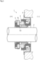
FIG. 1 is a cross-sectional view showing an example of a mechanical seal as a sliding component according to a first embodiment of the present invention. -
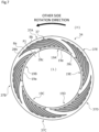
FIG. 2 is a front view showing a sliding surface of a stationary seal ring provided with an annular groove in the first embodiment. -
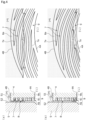
FIG. 3 is a partially enlarged schematic view showing a mode in which a fluid is introduced from the annular groove to dynamic pressure generation grooves in the first embodiment. -
FIG. 4A shows a partially enlarged schematic view of a sliding surface of a stationary seal ring between sliding surfaces at the time of initial sliding in the first embodiment andFIG. 4B shows a partially enlarged schematic view of the sliding surface of the stationary seal ring between the sliding surfaces at the time elapsed from the initial sliding in the first embodiment. -
FIG. 5 is a partially enlarged perspective view showing a modified example of the annular groove in the first embodiment. -
FIG. 6 is a front view showing a sliding surface of a stationary seal ring of a sliding component according to a second embodiment of the present invention. -
FIG. 7 is a front view showing a sliding surface of a stationary seal ring of a sliding component according to a third embodiment of the present invention. -
FIG. 8 is a front view showing a sliding surface of a stationary seal ring of a sliding component according to a fourth embodiment of the present invention. -
FIG. 9 is a front view showing a sliding surface of a stationary seal ring of a sliding component according to a fifth embodiment of the present invention. - Modes for carrying out a sliding component according to the present invention will be described based on embodiments.
- A sliding component according to a first embodiment of the present invention will be described with reference to
FIGS. 1 to 4 . A mode in which the sliding component is a mechanical seal will be described as an example. Further, a description will be made such that an outer radial side of the sliding component constituting the mechanical seal is a sealed liquid side (high pressure side) which is a sealed fluid side and an inner radial side is an atmosphere side (low pressure side) which is a leakage side. Further, for convenience of explanation, dots may be added to the bottom surface of the groove formed on the sliding surface in the drawings. Further, the shape of the groove shown in the drawings is different from the actual shape, and the depth direction is particularly emphasized. - As shown in
FIG. 1 , the sliding component of the first embodiment is an inside typemechanical seal 1 that is applied to a general industrial machine and seals a sealed fluid R which is about to leak from the outer radial side to the inner radial side of the sliding surface. Themechanical seal 1 is provided between a rotatingshaft 2 of a rotating machine such as a pump or a compressor (not shown) and aseal cover 3 fixed to a housing of the rotating machine and includes a stationary side element including an annularstationary seal ring 4 fixed to theseal cover 3 and a rotary side element including an annular rotatingseal ring 5 rotating together with the rotatingshaft 2. Themechanical seal 1 allows a sliding surface S1 of thestationary seal ring 4 and a sliding surface S2 of the rotatingseal ring 5 to slide closely with each other so that the sealed fluid R on the high pressure side (hereinafter, referred to as a high pressure side H) inside the machine is axially sealed and does not leak to the leakage side (hereinafter, referred to as a low pressure side L). - In addition, the sliding component is not limited to the mechanical seal, may be one in which a fluid is interposed between sliding surfaces, and may constitute a bearing or other machines.
- The
stationary seal ring 4 and the rotatingseal ring 5 are typically formed of SiC (as an example of hard material) or a combination of SiC (as an example of hard material) and carbon (as an example of soft material), but the invention is not limited thereto. The sliding material which can be used as the sliding material for the mechanical seal can be applied. In addition, examples of SiC include materials composed of two or more types of phases having different components and compositions, for example, SiC in which graphite particles are dispersed, reaction sintered SiC composed of SiC and Si, SiC-TiC, SiC-TiN, and the like as well as sintered bodies using boron, aluminum, carbon, and the like as sintering aids and examples of the carbon include resin-molded carbon, sintered carbon, and the like as well as carbon which is a mixture of carbonaceous and graphite. In addition to the above-described sliding materials, metal materials, resin materials, surface modification materials (e.g., coating materials), composite materials, and the like can also be applied. - As shown in
FIGS. 1 and2 , the rotatingshaft 2 is inserted through the annularstationary seal ring 4 and a plurality ofspiral grooves 7 are formed on the sliding surface S1 by surface texturing or the like. In addition, the rotatingseal ring 5 which is disposed to face the sliding surface S1 of thestationary seal ring 4 is provided to rotate in the counter-clockwise rotation direction (i.e., the direction indicated by the arrow in the drawing) with respect to thestationary seal ring 4. - The sliding surface S1 of the
stationary seal ring 4 is provided with thespiral grooves 7 which are formed at a plurality of positions (e.g., in the present embodiment, twenty positions) to be separated from each other at equal intervals along the circumferential direction as dynamic pressure generation grooves which extend while being curved from the inner radial side to the outer radial side and anannular groove 9 is formed as a recessed portion which is formed on the inner radial side in relation to thespiral grooves 7 in an annular shape. Theannular groove 9 is formed at the inner radial end portion of the sliding surface S1 and is opened to the low pressure side L over 360°. In thesespiral grooves 7, the inner radial side communicates with theannular groove 9 at acommunication portion 7a and the outer radial side is closed at a terminatedend portion 7e (seeFIG. 3 ) . - In addition, the sliding surface S2 of the rotating
seal ring 5 of this embodiment is formed as a flat surface and the flat surface is not provided with the dynamic pressure generation groove and the like. - The sliding surface S1 of the
stationary seal ring 4 will be described in detail with reference toFIG. 3 . The remaining region of the sliding surface S1 excluding thespiral groove 7 and theannular groove 9 is formed as aflat land portion 8. Further, theannular groove 9 includes abottom surface 9b which is parallel to theland portion 8 and aside surface 9c which is formed on the outer radial side and thebottom surface 9b and theside surface 9c are arranged to be orthogonal to each other. Anopening portion 9a in which aninner surface 4A of thestationary seal ring 4 is notched is formed on the inner radial side of theannular groove 9. - The
spiral groove 7 includes thecommunication portion 7a which communicates with theannular groove 9, thebottom surface 7b which is parallel to theland portion 8, anouter surface 7c and aninner surface 7d which are curved in an arc shape and face each other, and the terminatedend portion 7e and theouter surface 7c and theinner surface 7d which are separated from each other at equal intervals and are curved gradually narrow as they extend to the outer radial side at the terminatedend portion 7e continuous to them. From this, the positive pressure of the sealed fluid R flowing into thespiral groove 7 increases especially in the vicinity of the terminatedend portion 7e, the sliding surface S1 of thestationary seal ring 4 and the sliding surface S2 of therotating seal ring 5 are separated from each other, and a liquid film is formed between the sliding surfaces. - Further, the
bottom surface 9b of theannular groove 9, thecommunication portion 7a corresponding to the boundary between theannular groove 9 and thespiral groove 7, and thebottom surface 7b of thespiral groove 7 are formed at the same depth and the sealed fluid R can easily flow from theannular groove 9 into thespiral groove 7. - The
land portion 8 includes aninner land portion 8b which is formed between theadjacent spiral grooves 7 and anouter land portion 8a which is connected to theinner land portion 8b and is formed in an annular shape at the outer radial end portion of the sliding surface S1. Theinner land portion 8b and theouter land portion 8a are formed at the substantially same height and a positive pressure is generated by thespiral groove 7 when the sliding surface S1 of thestationary seal ring 4 and the sliding surface S2 of therotating seal ring 5 slide on each other, so that lubricity between the sliding surfaces S1 and S2 can be obtained. - Next, the mode of the sealed fluid R when the
stationary seal ring 4 and therotating seal ring 5 slide on each other will be schematically described with reference toFIGS. 4A and 4B . In the initial stage of sliding, the sliding surface S1 and the sliding surface S2 are in contact with each other and the fluid (atmosphere, etc.) on the low pressure side L is introduced into the plurality ofspiral grooves 7 of thestationary seal ring 4 by sliding, so that a slight positive pressure is generated between the sliding surfaces. From this, as shown inFIG. 4A , a slight gap is formed between the sliding surface S1 and the sliding surface S2 and the sealed fluid R on the high pressure side H flows between the sliding surfaces due to a pressure difference. The sealed fluid R passes through theouter land portion 8a of theland portion 8 and gradually moves to the inner radial side between theinner land portion 8b of the sliding surface S1 of thestationary seal ring 4 and therotating seal ring 5 and a part of the sealed fluid R flows into thespiral groove 7. - At this time, a part of the sealed fluid R flowing to the
spiral groove 7 flows toward the terminatedend portion 7e due to the rotation of therotating seal ring 5 and is supplied between the sliding surfaces as the positive pressure increases and thespiral groove 7 is filled with the sealed fluid R as the lubricity between the sliding surfaces increases. - Next, as shown in
FIG. 4B , the sealed fluid R reaches theannular groove 9 on the inner radial side of thespiral groove 7. That is, the sealed fluid R between the sliding surfaces is actively guided from the gap between the sliding surface S1 and the sliding surface S2 slightly separated from each other in the axial direction into theannular groove 9 by the gap formed between thebottom surface 9b of theannular groove 9 and the sliding surface S2 to be wider than the gap between the sliding surfaces. At this time, in this embodiment, since theannular groove 9 is provided with theopening portion 9a opened to the inner radial side, the sealed fluid R inside theannular groove 9 is guided toward theside surface 9c on the outer radial side due to a negative pressure to be described later or a centrifugal force generated by the sliding between therotating seal ring 5 and thestationary seal ring 4. Accordingly, the sealed fluid R does not easily leak from theannular groove 9 to the low pressure side L and is easily recovered to thespiral groove 7 communicating with the outer radial side of theannular groove 9. - Further, since a positive pressure is generated in the vicinity of the terminated
end portion 7e of thespiral groove 7 as described above, a negative pressure is generated in thecommunication portion 7a communicating with thespiral groove 7 and the sealed fluid R flowing through theannular groove 9 is introduced toward thecommunication portion 7a. The introduced sealed fluid R sequentially flows toward the terminatedend portion 7e. - As described above, since the
annular groove 9 including theopening portion 9a opened to the inner radial side is formed on the side of theinner surface 4A in relation to thespiral groove 7 of thestationary seal ring 4, the sealed fluid R interposed between the sliding surfaces and particularly the sealed fluid R not introduced into thespiral groove 7 can be guided into theannular groove 9 on the innermost radial side. That is, conventionally, the sealed fluid R leaking to the low pressure side L (the leakage side) can be introduced into thespiral groove 7 through theannular groove 9. For this, the outflow of the sealed fluid R to the low pressure side L is reduced and the recovery rate of the sealed fluid R that is about to leak can be improved. - In this way, in the
mechanical seal 1 in which the sliding surface S1 of thestationary seal ring 4 serving as any one sliding component of themechanical seal 1 serving as the pair of sliding components is provided with thespiral grooves 7 serving as the plurality of dynamic pressure generation grooves extending from the low pressure side L to the high pressure side H, the sliding surface S1 is provided with theannular groove 9 serving as the recessed portion extending in the circumferential direction and opened to the low pressure side L and theannular groove 9 communicates with thespiral groove 7. Accordingly, since the sealed fluid R leaking to the low pressure side L on theland portion 8 dividing theadjacent spiral grooves 7 is guided to theannular groove 9 and the sealed fluid R guided to theannular groove 9 is introduced into thespiral groove 7, the lubricity is excellent, the recovery rate of the sealed fluid R is high, and the leakage to the low pressure side L is prevented. - Further, since the
bottom surface 9b of theannular groove 9 is formed in thecommunication portion 7a as the boundary between theannular groove 9 and thespiral groove 7 to have the same depth as thebottom surface 7b of thespiral groove 7, the sealed fluid R inside theannular groove 9 is easily introduced into thespiral groove 7. - Further, since the
annular groove 9 is formed in an annular shape so that theannular groove 9 is formed over the entire circumference of one sliding surface S1, the sealed fluid R that is about to leak to the low pressure side L is easily guided into theannular groove 9. - Further, since the
annular groove 9 is formed at the inner radial end portion of one sliding surface S1, the sealed fluid R is easily guided into theannular groove 9 due to the centrifugal force generated by sliding. - Next, a modified example of the sliding component according to the present invention will be described with reference to
FIG. 5 . In addition, the same components as those shown in the first embodiment are designated by the same reference numerals, and duplicate description will be omitted. - As shown in
FIG. 5 , astationary seal ring 14 of a second embodiment includes anannular groove 90 provided with abottom surface 90b which is thinner than thebottom surface 9b of theannular groove 9 described in the first embodiment. That is, thebottom surface 90b of theannular groove 90 is formed to be higher than thebottom surface 7b of thespiral groove 7. Further, theannular groove 90 is formed at the inner radial end portion of the sliding surface S1 and is opened to the low pressure side L over 360°. Similarly to the first embodiment, allspiral grooves 7 communicate with theannular groove 90 and thecommunication portion 7a is provided with a part of theinner surface 7d which hangs down substantially vertically from thebottom surface 90b of theannular groove 90. - Further, the
bottom surface 90b of theannular groove 90 is formed at the same depth over the entire circumference. - In this way, since the
bottom surface 90b of theannular groove 90 is formed to be higher than thebottom surface 7b of thespiral groove 7, the sealed fluid R does not easily flow reversely from thespiral groove 7 to theannular groove 90 and the sealed fluid R does not easily leak to the low pressure side L. - Next, a second embodiment according to the sliding component of the present invention will be described with reference to
FIG. 6 . In addition, the same components as those shown in the above-described embodiment are designated by the same reference numerals, and duplicate description will be omitted. - As shown in
FIG. 6 , in astationary seal ring 24 of the second embodiment, a plurality of (e.g., seven in this embodiment)spiral grooves 27 are grouped in a bundle andspiral groove groups 27A to 27E as one group are provided in a plurality of groups (e.g., five groups in this embodiment) at equal intervals in the circumferential direction. Awide land portion 18b which is formed to have a wider width in the circumferential direction than theinner land portion 8b formed between theadjacent spiral grooves 27 is formed at five positions at equal intervals in the circumferential direction between thespiral groove groups 27A to 27E which are adjacent to each other in the circumferential direction. Further, a negativepressure generation groove 28 is formed on the outer radial side of eachwide land portion 18b to be curved and drilled from the outer radial end portion of thestationary seal ring 24 to the inner radial side. - Thus, the
outer land portion 18a is separated in the circumferential direction due to the formation of the negativepressure generation groove 28 and is disposed at five equal positions at the outer radial end portion. That is, in the sliding surface of thestationary seal ring 24, theouter land portion 18a, theinner land portion 8b, and thewide land portion 18b are formed to be connected to each other at the same height in the remaining region excluding thespiral groove groups 27A to 27E, theannular groove 9, and the negativepressure generation groove 28. - An outer
radial end portion 28a of the negativepressure generation groove 28 is opened to the high pressure side H and the sealed fluid R on the high pressure side H is introduced during sliding to generate a negative pressure between the sliding surfaces. Further, in the second embodiment, the bottom surfaces of theannular groove 9, thespiral groove 27, and the negativepressure generation groove 28 have the same depth. - When the
stationary seal ring 24 of the second embodiment slides on therotating seal ring 5 including the sliding surface S2 provided with the flat surface, a positive pressure is generated by thespiral groove groups 27A to 27E and a negative pressure is generated by the negativepressure generation groove 28 between the sliding surfaces. Accordingly, there is an effect of improving the sealing performance by suppressing the separation width between the sliding surfaces due to the negative pressure while maintaining the lubrication between the sliding surfaces due to the positive pressure. - Next, a sliding component according to a third embodiment of the present invention will be described with reference to
FIG. 7 . In addition, the same components as those shown in the above-described embodiment are designated by the same reference numerals, and duplicate description will be omitted. - As shown in
FIG. 7 , in astationary seal ring 34 of the third embodiment,arc grooves 19A to 19E are independently separated from each other at predetermined intervals in the circumferential direction unlike theannular groove 9 formed in an annular shape in the first and second embodiments. Then, in the third embodiment, thearc grooves 19A to 19E are arranged at equal intervals on the innermost radial side of thestationary seal ring 34 and include anopening portion 19a opened to the low pressure side L. - Each of the
arc grooves 19A to 19E communicates with aspiral groove 37 which is curved and extends in the circumferential direction. In the third embodiment, a plurality of (e.g., seven in this embodiment)spiral grooves 37 extend from one arc groove in a direction from the inner radial side to the outer radial side and a plurality of (e.g., five in this embodiment)spiral groove groups 37A to 37E are formed at equal intervals in the circumferential direction. Further, thearc grooves 19A to 19E and thespiral groove groups 37A to 37E are formed to have the same depth. - A
wide land portion 28b which is formed to have a wider width in the circumferential direction than theinner land portion 8b formed between theadjacent spiral grooves 27 is formed at five positions at equal intervals in the circumferential direction between thespiral groove groups 37A to 37E which are adjacent to each other in the circumferential direction. Further, an innerend land portion 28c which is connected to the inner radial end portion of thewide land portion 28b is formed between thearc grooves 19A to 19E which are adjacent to each other in the circumferential direction and thearc grooves 19A to 19E are separated from each other in the circumferential direction. That is, in the sliding surface of thestationary seal ring 34, theouter land portion 8a, theinner land portion 8b, thewide land portion 28b, and the innerend land portion 28c are formed to be connected to each other at the same height in the remaining region excluding thespiral groove groups 37A to 37E and thearc grooves 19A to 19E. - Further, a description will be made with reference to, for example, a virtual line P1 extending in the radial direction of
FIG. 7 . Thearc groove 19B communicating with thespiral groove group 37B is disposed to radially overlap the plurality ofspiral groove groups 37A provided to extend and communicate with theupstream arc groove 19A adjacent to thearc groove 19B. - From this, since the
arc groove 19B is disposed to radially overlap thespiral groove group 37A extending from theadjacent arc groove 19A, the sealed fluid R flowing to the low pressure side L over thewide land portion 28b from thespiral groove 37A extending from theupstream arc groove 19A in the rotation direction can be efficiently recovered to thedownstream arc groove 19B. - Next, a sliding component according to a fourth embodiment of the present invention will be described with reference to
FIG. 8 . In addition, the same components as those shown in the above-described embodiment are designated by the same reference numerals, and duplicate description will be omitted. - In the fourth embodiment, the inner radial side of the sliding component will be described as the sealed fluid side (i.e., the high pressure side H), the outer radial side will be described as the leakage side (i.e., the low pressure side L), and a
stationary seal ring 44 capable of sealing the sealed fluid R that is about to leak from the inner radial side to the outer radial side at the sliding portion between the rotating seal ring and the stationary seal ring will be described. - As shown in
FIG. 8 , the sliding surface of thestationary seal ring 44 of the fourth embodiment is provided with a spiral groove 47 which is formed at a plurality of positions (e.g., twenty positions in this embodiment) in the circumferential direction to extend while being curved from the outer radial side to the inner radial side and anannular groove 29 is formed in an annular shape on the outer radial side of the spiral groove 47. Theannular groove 29 is formed at the outer radial end portion and is provided with anopening portion 29a opened to the low pressure side L over 360°. In these spiral grooves 47, the outer radial side communicates with theannular groove 29 and the inner radial side is closed. Additionally, theannular groove 29 and the spiral groove 47 are formed to have the same depth. - In a remaining region excluding the spiral groove 47 and the
annular groove 29, aninner land portion 38b formed between the adjacent spiral grooves 47 and an innerannular land portion 38a formed in an annular shape at the inner peripheral end portion are formed to be connected to each other at the same height. - With the above-described configuration of the fourth embodiment, since the sliding surface of the
stationary seal ring 44 is provided with theannular groove 29 which extends in the circumferential direction and is opened to the low pressure side L and theannular groove 29 communicates with the spiral groove 47, the sealed fluid R leaking to the low pressure side L on the land portion 38 dividing the spiral groove 47 is guided to theannular groove 29 and the sealed fluid R guided to theannular groove 29 is introduced to the spiral groove 47. Accordingly, the lubricity is excellent, the recovery rate of the sealed fluid R is high, and the leakage to the low pressure side L is prevented. - Next, a sliding component according to a fifth embodiment of the present invention will be described with reference to
FIG. 9 . In addition, the same components as those shown in the above-described embodiment are designated by the same reference numerals, and duplicate description will be omitted. In the fifth embodiment, astationary seal ring 54 slides relative to a rotating seal ring (not shown) that rotates in both directions in the circumferential direction. - As shown in
FIG. 9 , the sliding surface of thestationary seal ring 54 of the fifth embodiment is provided with anannular groove 39 which is formed at the inner radial end portion and is opened to the low pressure side L over 360° and a plurality ofgroove portions 50 which communicate with theannular groove 39 and are separated from each other in the circumferential direction. Eachgroove portion 50 includes acenter groove 50A which includes an openingportion 51 communicating with theannular groove 39 and extends in the circumferential direction, afirst side groove 50B which obliquely extends in a linear shape in the radial direction from one end portion of thecenter groove 50A in the circumferential direction, and asecond side groove 50C which obliquely extends in a linear shape in the radial direction from the other end portion of thecenter groove 50A in the circumferential direction. Further, theannular groove 39 and thegroove portion 50 are formed to have the same depth. - In the
first side groove 50B, a terminatedend portion 50D thereof is formed at an acute angle in the circumferential direction. Similarly, in thesecond side groove 50C, a terminatedend portion 50E thereof is formed at an acute angle in the circumferential direction. That is, thegroove portion 50 is formed line-symmetrically with reference to a virtual line P2 extending in the radial direction through the center in the circumferential direction of thecenter groove 50A. Further, a remaining region excluding theannular groove 39 and thegroove portion 50 is formed as aflat land portion 48 and is formed to be connected at the same height. - In
FIG. 9 , when the rotating seal ring (not shown) rotates in the counter-clockwise rotation direction of the drawing paper with respect to thestationary seal ring 54, for example, as indicated by a solid arrow, the sealed fluid R on the low pressure side L inside thegroove portion 50 is converged toward the terminatedend portion 50D of thefirst side groove 50B and flows out between the sliding surfaces. - On the other hand, when the rotating seal ring (not shown) rotates in the clockwise rotation direction of the drawing paper with respect to the
stationary seal ring 54 as indicated by a dotted arrow inFIG. 9 , the sealed fluid R on the low pressure side L inside thegroove portion 50 is converged toward the terminatedend portion 50E of thesecond side groove 50C and flows out between the sliding surfaces. - The sealed fluid R passing through the
land portion 48 between the sliding surfaces to the inner radial side is guided to theannular groove 39 formed at the inner radial end portion and is introduced into thegroove portion 50. - In this way, since the
groove portion 50 is formed line-symmetrically with respect to the virtual line P2, the groove portion can be used not only in the relative rotation direction between thestationary seal ring 54 and therotating seal ring 5. Further, since theannular groove 39 is formed, the recovery rate of the sealed fluid R is high. - Although the embodiments of the present invention have been described above with reference to the drawings, the detailed configuration is not limited to the first to fifth embodiments and the modified example and modifications or additions in the scope not departing from the spirit of the present invention are also included in the present invention.
- For example, in the second to fifth embodiments, a case has been described in which the annular groove and the arc groove serving as the arc-shaped recesses and the spiral groove and the groove portion serving as the dynamic pressure generation grooves are formed at the same depth, but the present invention is not limited thereto. For example, the recessed portion and the dynamic pressure generation groove may be formed at different depths as shown in the modified example of the first embodiment.
- Further, a case has been described in which the
bottom surface 9b of theannular groove 9 and thebottom surface 7b of thespiral groove 7 are parallel to theland portion 8, but the present invention is not limited thereto. For example, these bottom surfaces may be arranged to be inclined to the inner radial side or the outer radial side. - Further, the radial width of the
annular groove 9 may not be equal over the entire circumference. - Further, the
annular groove 9 is formed at the inner radial end portion of thestationary seal ring 4, but the annular groove may be also provided in the vicinity of the center portion in addition to the inner radial end portion as a double annular groove on the sliding surface. - Further, in the above-described embodiment, a case has been described in which the
annular groove 9 and thespiral groove 7 are formed in thestationary seal ring 4, but the present invention is not limited thereto. For example, the annular groove and the spiral groove may be provided in the rotating seal ring and the sliding surface of the stationary seal ring may be a flat surface. -
- 1
- Mechanical seal (sliding component)
- 2
- Rotating shaft
- 3
- Seal cover
- 4
- Stationary seal ring (sliding member)
- 5
- Rotating seal ring (sliding member)
- 7
- Spiral groove (dynamic pressure generation groove)
- 7a
- Communication portion
- 8
- Land portion
- 8a
- Outer land portion
- 8b
- Inner land portion
- 9
- Annular groove (recessed portion)
- 9a
- Opening portion
- 14
- Stationary seal ring (sliding member)
- 19A to 19E
- Arc groove (arc-shaped recess)
- 24
- Stationary seal ring (sliding member)
- 27
- Spiral groove (dynamic pressure generation groove)
- 27A to 27E
- Spiral groove group
- 28
- Negative pressure generation groove
- 29
- Annular groove (recessed portion)
- 34
- Stationary seal ring (sliding member)
- 37
- Spiral groove (dynamic pressure generation groove)
- 37A to 37E
- Spiral groove group
- 39
- Annular groove (recessed portion)
- 44
- Stationary seal ring (sliding member)
- 47
- Spiral groove (dynamic pressure generation groove)
- 50
- Groove portion (dynamic pressure generation groove)
- 54
- Stationary seal ring (sliding member)
- 90
- Annular groove (recessed portion)
- Particular embodiments of the present invention may comprise the sets of features listed in the following numbered
statements 1 to 6. - A sliding component comprising a pair of sliding members, one of the sliding members having a sliding surface provided with a plurality of dynamic pressure generation grooves extending from a leakage side to a sealed fluid side,
- wherein the sliding surface is provided with a recessed portion extending in a circumferential direction and opened to the leakage side, and
- wherein the recessed portion communicates with the dynamic pressure generation grooves.
- The sliding component according to
statement 1,
wherein a bottom surface of the recessed portion is formed to be equal in depth to a bottom surface of each of the dynamic pressure generation grooves at a boundary between the recessed portion and each of the dynamic pressure generation grooves. - The sliding component according to
statement 1,
wherein a bottom surface of the recessed portion is formed to be higher than a bottom surface of each of the dynamic pressure generation grooves at a boundary between the recessed portion and each of the dynamic pressure generation grooves. - The sliding component according to any one of
statements 1 to 3, - wherein the recessed portion is formed by a plurality of arc-shaped recesses separately arranged in a circumferential direction, and
- each of the arc-shaped recesses is disposed so as to overlap, in a radially directional view, with a part of the dynamic pressure generation grooves communicating with adjacent one of the arc-shaped recesses.
- The sliding component according to any one of
statements 1 to 3,
wherein the recessed portion is formed in an annular shape. - The sliding component according to any one of
statements 1 to 5,
wherein the recessed portion is formed at an inner radial end of the sliding surface.
Claims (4)
- A sliding component comprising a pair of sliding members, one of the sliding members having a sliding surface provided with a plurality of dynamic pressure generation grooves extending from a leakage side to a sealed fluid side,wherein the sliding surface is provided with a recessed portion extending in a circumferential direction and opened to the leakage side, andwherein the recessed portion is an annular groove and communicates with the dynamic pressure generation grooves,the recessed portion is provided with an opening portion in which a peripheral surface of the one of the sliding members on the leakage side is notched and which is opened to the leakage side over 360°,the dynamic pressure generation grooves are spiral grooves each of which has one radial end portion communicating with the recessed portion and the other radial end portion formed as a closed end, the spiral grooves extending while being curved from the leakage side to the sealed fluid side,in a remaining region of the sliding surface excluding the dynamic pressure generation grooves and the recessed portion, an inner land portion formed between the adjacent dynamic pressure generation grooves and an annular land portion formed in an annular shape are formed to be connected to each other at the same height.
- The sliding component according to claim 1,
wherein the sealed fluid side is an outer radial side of the sliding surface, and the leakage side is an inner radial side of the sliding surface. - The sliding component according to claim 1,
wherein the sealed fluid side is an inner radial side of the sliding surface, and the leakage side is an outer radial side of the sliding surface. - The sliding component according to any one of claims 1 to 3,
wherein a bottom surface of the recessed portion is formed to be equal in depth to a bottom surface of each of the dynamic pressure generation grooves at a boundary between the recessed portion and each of the dynamic pressure generation grooves.
Applications Claiming Priority (3)
| Application Number | Priority Date | Filing Date | Title |
|---|---|---|---|
| JP2019137952 | 2019-07-26 | ||
| PCT/JP2020/027005 WO2021020074A1 (en) | 2019-07-26 | 2020-07-10 | Sliding component |
| EP20847261.3A EP4006368A4 (en) | 2019-07-26 | 2020-07-10 | Sliding component |
Related Parent Applications (1)
| Application Number | Title | Priority Date | Filing Date |
|---|---|---|---|
| EP20847261.3A Division EP4006368A4 (en) | 2019-07-26 | 2020-07-10 | Sliding component |
Publications (1)
| Publication Number | Publication Date |
|---|---|
| EP4345342A2 true EP4345342A2 (en) | 2024-04-03 |
Family
ID=74230287
Family Applications (3)
| Application Number | Title | Priority Date | Filing Date |
|---|---|---|---|
| EP24157861.6A Pending EP4345342A2 (en) | 2019-07-26 | 2020-07-10 | Sliding component |
| EP24157883.0A Pending EP4345343A2 (en) | 2019-07-26 | 2020-07-10 | Sliding component |
| EP20847261.3A Pending EP4006368A4 (en) | 2019-07-26 | 2020-07-10 | Sliding component |
Family Applications After (2)
| Application Number | Title | Priority Date | Filing Date |
|---|---|---|---|
| EP24157883.0A Pending EP4345343A2 (en) | 2019-07-26 | 2020-07-10 | Sliding component |
| EP20847261.3A Pending EP4006368A4 (en) | 2019-07-26 | 2020-07-10 | Sliding component |
Country Status (6)
| Country | Link |
|---|---|
| US (1) | US11892081B2 (en) |
| EP (3) | EP4345342A2 (en) |
| JP (1) | JP7399966B2 (en) |
| KR (1) | KR20220024958A (en) |
| CN (1) | CN114127430A (en) |
| WO (1) | WO2021020074A1 (en) |
Families Citing this family (7)
| Publication number | Priority date | Publication date | Assignee | Title |
|---|---|---|---|---|
| EP3842673A4 (en) | 2018-08-24 | 2022-05-04 | Eagle Industry Co., Ltd. | Sliding member |
| EP4198353A1 (en) | 2018-11-30 | 2023-06-21 | Eagle Industry Co., Ltd. | Sliding component |
| KR102541901B1 (en) * | 2018-12-21 | 2023-06-13 | 이구루코교 가부시기가이샤 | sliding parts |
| WO2020166590A1 (en) | 2019-02-14 | 2020-08-20 | イーグル工業株式会社 | Sliding component |
| EP4345342A2 (en) | 2019-07-26 | 2024-04-03 | Eagle Industry Co., Ltd. | Sliding component |
| EP4328460A1 (en) * | 2021-04-23 | 2024-02-28 | Eagle Industry Co., Ltd. | Sliding component |
| WO2023053964A1 (en) * | 2021-09-28 | 2023-04-06 | イーグル工業株式会社 | Sliding component |
Citations (1)
| Publication number | Priority date | Publication date | Assignee | Title |
|---|---|---|---|---|
| JP6444492B2 (en) | 2015-04-15 | 2018-12-26 | イーグル工業株式会社 | Sliding parts |
Family Cites Families (169)
| Publication number | Priority date | Publication date | Assignee | Title |
|---|---|---|---|---|
| JPS366305B1 (en) | 1960-03-31 | 1961-05-30 | ||
| US3085808A (en) | 1960-05-17 | 1963-04-16 | Worthington Corp | Mechanical seal with controlled leakage |
| US3232680A (en) | 1963-08-19 | 1966-02-01 | Whittaker Corp | Fluid bearing |
| US3410565A (en) | 1966-07-27 | 1968-11-12 | Worthington Corp | Centrifugal and face contact seal |
| FR1505487A (en) | 1966-10-28 | 1967-12-15 | Guinard Pompes | Improvement in leak-controlled rotary joints |
| US3466052A (en) | 1968-01-25 | 1969-09-09 | Nasa | Foil seal |
| US3499653A (en) | 1968-06-05 | 1970-03-10 | Crane Packing Co | Rotary mechanical seal of the gap type |
| US3656227A (en) | 1970-03-26 | 1972-04-18 | Gen Motors Corp | Method of making a mold for bidirectional hydrodynamic shaft seals |
| US3804424A (en) | 1972-04-24 | 1974-04-16 | Crane Packing Co | Gap seal with thermal and pressure distortion compensation |
| JPS4933614A (en) | 1972-07-24 | 1974-03-28 | ||
| NL7213192A (en) | 1972-09-29 | 1974-04-02 | ||
| US3855624A (en) | 1973-08-15 | 1974-12-17 | Philips Corp | Grooved air bearing head |
| DE2504204C3 (en) | 1975-02-01 | 1981-11-12 | Skf Kugellagerfabriken Gmbh, 8720 Schweinfurt | Self-pressure generating axial slide bearing |
| JPS5271858U (en) | 1975-11-25 | 1977-05-28 | ||
| JPS5477305A (en) | 1977-12-02 | 1979-06-20 | Hitachi Constr Mach Co Ltd | Compound pump motor |
| JPS5724220A (en) | 1980-07-21 | 1982-02-08 | Dainippon Printing Co Ltd | Mold device for injection molding |
| JPS57146955A (en) | 1981-03-06 | 1982-09-10 | Shinsaku Kaguchi | Sealing device for rotary member |
| JPS58109771A (en) | 1981-12-23 | 1983-06-30 | Eagle Ind Co Ltd | Non-contact type mechanical seal |
| JPS58137667A (en) | 1982-02-10 | 1983-08-16 | Nippon Seiko Kk | Magnetic fluid seal |
| US4486026A (en) | 1982-02-10 | 1984-12-04 | Nippon Seiko K.K. | Sealing and bearing means by use of ferrofluid |
| JPS5958252A (en) | 1982-09-29 | 1984-04-03 | Honda Motor Co Ltd | V belt transmission device |
| US4406466A (en) | 1982-11-29 | 1983-09-27 | Elliott Turbomachinery Co., Inc. | Gas lift bearing and oil seal |
| JPS60107461A (en) | 1983-11-15 | 1985-06-12 | Jidosha Kiki Co Ltd | Method of controlling power steering device |
| JPS60119021U (en) | 1984-01-20 | 1985-08-12 | 松下電器産業株式会社 | Headed bar alignment and feeding device |
| JPH06100642B2 (en) | 1984-09-29 | 1994-12-12 | 株式会社東芝 | Optical applied magnetic field sensor |
| JPS6237572A (en) | 1985-08-12 | 1987-02-18 | Ebara Res Co Ltd | Shaft seal device |
| DE3619489A1 (en) | 1986-06-10 | 1987-12-17 | Gutehoffnungshuette Man | Shaft seal |
| JPS6333027A (en) | 1986-07-28 | 1988-02-12 | Nippon Hoso Kyokai <Nhk> | Sound digital signal transmission system |
| CH677266A5 (en) | 1986-10-28 | 1991-04-30 | Pacific Wietz Gmbh & Co Kg | |
| US5246295A (en) * | 1991-10-30 | 1993-09-21 | Ide Russell D | Non-contacting mechanical face seal of the gap-type |
| JPH0620155Y2 (en) | 1987-09-11 | 1994-05-25 | シチズン時計株式会社 | Clock time adjustment mechanism |
| JPH01133572A (en) | 1987-11-16 | 1989-05-25 | Sanyo Electric Co Ltd | Single-phase frequency conversion circuit |
| JPH06105105B2 (en) | 1989-03-03 | 1994-12-21 | 日本ピラー工業株式会社 | Non-contact end face mechanical seal |
| JPH0314371A (en) | 1989-06-13 | 1991-01-23 | Fuji Photo Film Co Ltd | Image oscillation correcting device for video camera |
| JPH0335372A (en) | 1989-06-30 | 1991-02-15 | Mita Ind Co Ltd | Image deciding device |
| JP2554542B2 (en) | 1989-07-06 | 1996-11-13 | 株式会社 藤井合金製作所 | Gas cock manufacturing method |
| JPH0341267A (en) | 1989-07-07 | 1991-02-21 | Mitsuwa Gas Kiki Kk | Manufacture of cast iron gas cock |
| JPH0335372U (en) * | 1989-08-14 | 1991-04-05 | ||
| JPH0341268U (en) * | 1989-08-31 | 1991-04-19 | ||
| JPH0660691B2 (en) | 1990-04-17 | 1994-08-10 | イーグル工業株式会社 | Double rotation type semi-contact mechanical seal and groove machining method for ring sliding surface |
| US5492341A (en) | 1990-07-17 | 1996-02-20 | John Crane Inc. | Non-contacting, gap-type seal having a ring with a patterned seal face |
| JPH0496671A (en) | 1990-08-11 | 1992-03-30 | Omron Corp | Harmonic drive electrostatic motor |
| JPH04145267A (en) | 1990-10-08 | 1992-05-19 | Ebara Corp | Noncontact end-face seal |
| GB9103217D0 (en) | 1991-02-15 | 1991-04-03 | Crane John Uk Ltd | Mechanical face seals |
| JPH0590048A (en) | 1991-09-25 | 1993-04-09 | Nissin Electric Co Ltd | Voltage transformer for insulating gas-filled switchgear |
| DE4303237A1 (en) | 1992-02-06 | 1993-10-21 | Eagle Ind Co Ltd | Gas seal |
| US5201531A (en) | 1992-04-02 | 1993-04-13 | John Crane Inc. | Face seal with double spiral grooves |
| JPH0769019B2 (en) | 1992-05-18 | 1995-07-26 | 日本ピラー工業株式会社 | Non-contact mechanical seal |
| GB9214282D0 (en) | 1992-07-04 | 1992-08-19 | Crane John Uk Ltd | Seals |
| US5501470A (en) | 1992-12-11 | 1996-03-26 | Nippon Pillar Packing Co., Ltd. | Non-contacting shaft sealing device with grooved face pattern |
| US5441283A (en) | 1993-08-03 | 1995-08-15 | John Crane Inc. | Non-contacting mechanical face seal |
| BR9407404A (en) | 1993-09-01 | 1996-11-05 | Durametallic Corp | Fluid sealing device |
| US5498007A (en) | 1994-02-01 | 1996-03-12 | Durametallic Corporation | Double gas barrier seal |
| DE4407453A1 (en) | 1994-03-05 | 1995-09-07 | Albrecht Dipl Ing Kayser | Thrust bearing with helix grooves for oil and gas sealing |
| JP2563081B2 (en) | 1994-03-22 | 1996-12-11 | 日本ピラー工業株式会社 | Non-contact type shaft sealing device |
| JP3387236B2 (en) | 1994-09-22 | 2003-03-17 | 株式会社島津製作所 | Biomagnetic measurement device |
| JPH09329247A (en) | 1996-06-11 | 1997-12-22 | Ebara Corp | Non-contact end surface seal |
| JP2999415B2 (en) | 1996-07-24 | 2000-01-17 | 日本ピラー工業株式会社 | mechanical seal |
| JPH10281299A (en) | 1997-04-11 | 1998-10-23 | Mitsubishi Heavy Ind Ltd | Mechanical seal device |
| US5895051A (en) | 1997-07-16 | 1999-04-20 | Freudenberg-Nok General Partnership | Noise abating beads on a rack seal |
| JPH1151043A (en) | 1997-08-05 | 1999-02-23 | Seiko Instr Inc | Fluid dynamic pressure bearing, spindle motor incorporating this bearing and rotor device incorporating this spindle motor |
| US6142478A (en) | 1998-02-06 | 2000-11-07 | John Crane Inc. | Gas lubricated slow speed seal |
| PL187630B1 (en) * | 1998-12-10 | 2004-08-31 | Anga Uszczelnienia Mechaniczne | Contactless mechanical end-face seal |
| JP4075170B2 (en) | 1998-12-17 | 2008-04-16 | 松下電器産業株式会社 | Hydrodynamic bearing device and spindle motor using the same |
| US6189896B1 (en) | 1999-04-08 | 2001-02-20 | Caterpillar Inc. | Controlled leakage rotating seal ring with elements for receiving and holding a lubricant on a face thereof |
| JP2001295833A (en) | 2000-04-18 | 2001-10-26 | Matsushita Electric Ind Co Ltd | Thrust dynamic pressure bearing |
| JP2001317638A (en) | 2000-05-02 | 2001-11-16 | Mitsubishi Heavy Ind Ltd | Seal structure and compressor |
| US6446976B1 (en) | 2000-09-06 | 2002-09-10 | Flowserve Management Company | Hydrodynamic face seal with grooved sealing dam for zero-leakage |
| CN1167890C (en) | 2001-01-18 | 2004-09-22 | 王玉明 | Spiral groove end sealer capable of being rotated in both directions |
| CN2460801Y (en) | 2001-01-18 | 2001-11-21 | 王玉明 | Sealing device for spiral flute end capable of bidirectional rotation |
| JP3984462B2 (en) | 2001-11-26 | 2007-10-03 | 日本電産株式会社 | Hydrodynamic bearing device |
| CN2534429Y (en) | 2001-12-27 | 2003-02-05 | 中国石油天然气股份有限公司 | Double-row same direction fluid dynamic pressure tank upper-stream pumping mechanical seal |
| US6902168B2 (en) | 2002-03-19 | 2005-06-07 | Eagle Industry Co., Ltd. | Sliding element |
| JP4495402B2 (en) | 2002-03-19 | 2010-07-07 | イーグル工業株式会社 | Sliding parts |
| JP4205910B2 (en) | 2002-04-02 | 2009-01-07 | イーグル工業株式会社 | Sliding parts |
| EP2263686B1 (en) | 2002-07-18 | 2012-12-26 | University of Washington | Pharmaceutical compositions comprising immunologically active herpes simplex virus (HSV) protein fragments |
| CN100427816C (en) * | 2002-09-20 | 2008-10-22 | 徐万福 | Helical flute and face mechanial seal composed of angular microflute group |
| JP4316956B2 (en) | 2002-10-23 | 2009-08-19 | イーグル工業株式会社 | Sliding parts |
| US7540664B2 (en) | 2003-01-21 | 2009-06-02 | Seagate Technology Llc | Grooves on both the moving and the stationary mating fluid dynamic bearing surfaces for performance enhancement |
| US7160031B2 (en) | 2003-11-20 | 2007-01-09 | Matsushita Electric Industrial Co., Ltd. | Thrust dynamic pressure bearing, spindle motor using the same, and information recording and reproducing apparatus using them |
| JP4719414B2 (en) | 2003-12-22 | 2011-07-06 | イーグル工業株式会社 | Sliding parts |
| JP2005188651A (en) | 2003-12-25 | 2005-07-14 | Yamada Seisakusho Co Ltd | Mechanical seal in water pump |
| US7568839B2 (en) | 2004-02-18 | 2009-08-04 | Seiko Instruments Inc. | Fluid dynamic pressure bearing, motor, and recording medium driving device |
| GB2413603A (en) | 2004-04-30 | 2005-11-02 | Corac Group Plc | A dry gas seal assembly |
| JP4700394B2 (en) | 2004-05-12 | 2011-06-15 | ミネベア株式会社 | Fluid dynamic pressure bearing, spindle motor equipped with the fluid dynamic pressure bearing, and recording disk drive |
| JP2006009828A (en) | 2004-06-22 | 2006-01-12 | Citizen Fine Tech Co Ltd | Dynamic pressure fluid bearing device |
| JP4322747B2 (en) | 2004-07-06 | 2009-09-02 | イーグル工業株式会社 | Sealing device |
| JP4262656B2 (en) | 2004-09-10 | 2009-05-13 | 日本ピラー工業株式会社 | Non-contact type sealing device |
| KR100630709B1 (en) | 2004-11-03 | 2006-10-02 | 삼성전자주식회사 | Hydro dynamic bearing and hard disk drive employing the same |
| KR101119547B1 (en) | 2004-11-09 | 2012-02-28 | 이글 고오교 가부시키가이샤 | Mechanical seal device |
| US7780399B1 (en) | 2006-01-12 | 2010-08-24 | Stein Seal Company | Reverse pressure double dam face seal |
| US8162322B2 (en) | 2006-10-25 | 2012-04-24 | Rexnord Industries, Llc | Hydrodynamic seal with circumferentially varying lift force |
| JP2008144864A (en) | 2006-12-11 | 2008-06-26 | Nok Corp | Thrust bearing |
| US7770895B2 (en) | 2007-05-01 | 2010-08-10 | Eaton Corporation | Segmented seal portion and assembly |
| US8360436B2 (en) | 2008-01-11 | 2013-01-29 | Eagle Industry Co., Ltd. | Mechanical seal sliding member, and mechanical seal |
| JP2009250378A (en) | 2008-04-08 | 2009-10-29 | Eagle Ind Co Ltd | Mechanical seal device for liquid |
| US8205891B2 (en) | 2008-09-15 | 2012-06-26 | Stein Seal Company | Intershaft seal assembly |
| JP2010133496A (en) | 2008-12-04 | 2010-06-17 | Eagle Ind Co Ltd | Sliding part |
| JP5367423B2 (en) | 2009-03-17 | 2013-12-11 | イーグル工業株式会社 | Sealing device |
| CN201582390U (en) | 2009-09-08 | 2010-09-15 | 江苏大学 | Novel mechanical sealing ring with circumferential through groove added at inner-diameter end of radial spiral groove |
| JP5271858B2 (en) | 2009-09-29 | 2013-08-21 | アイシン精機株式会社 | Mechanical seal and liquid pump |
| CN101749431B (en) | 2010-01-28 | 2013-07-31 | 浙江工业大学 | Mechanical sealing structure of pearl-row-like annular groove zoning end face |
| JPWO2011105513A1 (en) | 2010-02-26 | 2013-06-20 | Nok株式会社 | Seal ring |
| JP5518527B2 (en) | 2010-03-04 | 2014-06-11 | イーグル工業株式会社 | Sliding parts |
| CN101776152B (en) | 2010-03-05 | 2013-08-21 | 北京化工大学 | Outside pressurized type dynamic and static pressure gas lubricating and sealing device |
| JP5583440B2 (en) | 2010-03-18 | 2014-09-03 | イーグル工業株式会社 | Mechanical seal sliding material and mechanical seal |
| JP5122607B2 (en) | 2010-06-17 | 2013-01-16 | キヤノンマシナリー株式会社 | Flat sliding mechanism |
| US8814433B2 (en) | 2010-10-06 | 2014-08-26 | Eagle Industry Co., Ltd. | Sliding component |
| US9039013B2 (en) | 2011-05-04 | 2015-05-26 | United Technologies Corporation | Hydrodynamic non-contacting seal |
| BR112014000038B1 (en) | 2011-07-01 | 2020-10-06 | Eaton Corporation | HYDRODYNAMIC FACE SEAL |
| CN103620277B (en) | 2011-08-05 | 2016-08-17 | 伊格尔工业股份有限公司 | Mechanical sealing member |
| JP5881716B2 (en) | 2011-09-10 | 2016-03-09 | イーグル工業株式会社 | Sliding parts |
| CN104334939B (en) | 2012-08-04 | 2017-05-31 | 伊格尔工业股份有限公司 | Slide unit |
| JP6058018B2 (en) | 2012-09-29 | 2017-01-11 | イーグル工業株式会社 | Sliding parts |
| US20150240950A1 (en) | 2012-10-19 | 2015-08-27 | EagleBurgmann Japan Co., Ltd. | Bellows Seal |
| US9151389B2 (en) | 2012-12-25 | 2015-10-06 | Eagle Industry Co., Ltd. | Sliding component |
| WO2014103631A1 (en) | 2012-12-25 | 2014-07-03 | イーグル工業株式会社 | Sliding component |
| JP6211009B2 (en) | 2013-01-16 | 2017-10-11 | イーグル工業株式会社 | Sliding parts |
| US9574666B2 (en) | 2013-01-23 | 2017-02-21 | Flowserve Management Company | Mechanical face seal with a reverse trapezoidal face pattern |
| EP2977654B1 (en) | 2013-03-17 | 2018-04-25 | Eagle Industry Co., Ltd. | Sliding component |
| CN104769341B (en) | 2013-03-17 | 2017-04-05 | 伊格尔工业股份有限公司 | Slide unit |
| CN104919229B (en) | 2013-04-24 | 2017-05-31 | 伊格尔工业股份有限公司 | Slide unit |
| CN103267132B (en) | 2013-05-28 | 2015-08-05 | 南京林业大学 | From the mechanical seal of pumping Hydrodynamic pressure type |
| US20160252182A1 (en) | 2013-11-22 | 2016-09-01 | Eagle Industry Co., Ltd. | Sliding parts |
| JP6345695B2 (en) | 2013-12-09 | 2018-06-20 | イーグル工業株式会社 | Sliding parts |
| WO2015087799A1 (en) | 2013-12-09 | 2015-06-18 | イーグル工業株式会社 | Sliding component |
| KR20160098451A (en) * | 2014-01-24 | 2016-08-18 | 엔오케이 가부시키가이샤 | Seal ring |
| CN103791097A (en) | 2014-02-28 | 2014-05-14 | 江苏大学 | Combination fluid dynamic pressure groove mechanical seal ring capable of automatically discharging particles |
| CN104019237B (en) | 2014-05-29 | 2016-12-07 | 浙江工业大学 | Deep trouth annulus dynamic pressure type end surface mechanical sealing structure |
| US9353865B2 (en) | 2014-06-03 | 2016-05-31 | Thermo King Corporation | Mechanical face seal |
| EP3156699B1 (en) | 2014-06-10 | 2019-01-09 | NOK Corporation | Seal device |
| EP2975306B1 (en) | 2014-07-18 | 2017-06-14 | LEONARDO S.p.A. | Sealing ring |
| CN104165229A (en) | 2014-07-30 | 2014-11-26 | 浙江工业大学 | Mechanical seal structure for end faces of liquid lubricating ring grooves |
| CN106574725B (en) | 2014-09-04 | 2019-04-16 | 伊格尔工业股份有限公司 | Mechanical sealing member |
| JP6224568B2 (en) | 2014-10-17 | 2017-11-01 | イーグル工業株式会社 | mechanical seal |
| EP3252354A4 (en) * | 2015-01-31 | 2018-10-17 | Eagle Industry Co., Ltd. | Sliding part |
| KR101951585B1 (en) * | 2015-03-16 | 2019-02-22 | 엔오케이 가부시키가이샤 | Seal Ring |
| JP6245406B2 (en) * | 2015-03-16 | 2017-12-13 | Nok株式会社 | Seal ring |
| CN107532726B (en) | 2015-05-19 | 2020-09-22 | 伊格尔工业股份有限公司 | Sliding component |
| BR112017024683A2 (en) | 2015-05-21 | 2018-07-24 | Eagle Industry Co., Ltd. | sliding component |
| WO2016203878A1 (en) | 2015-06-15 | 2016-12-22 | イーグル工業株式会社 | Sliding part |
| CN107709852B (en) | 2015-06-27 | 2020-05-12 | 伊格尔工业股份有限公司 | Sliding component |
| WO2017002774A1 (en) | 2015-06-30 | 2017-01-05 | イーグル工業株式会社 | Seal device |
| CN109563934A (en) | 2016-08-15 | 2019-04-02 | 伊格尔工业股份有限公司 | Slide unit |
| JP6881882B2 (en) | 2016-09-14 | 2021-06-02 | イーグル工業株式会社 | mechanical seal |
| CN206017723U (en) | 2016-09-14 | 2017-03-15 | 中国石油大学(华东) | Envelope line style hydrodynamic lubrication end surface mechanical sealing structure |
| CN109906330B (en) | 2016-10-14 | 2021-12-14 | 伊格尔工业股份有限公司 | Sliding component |
| CN106439037B (en) | 2016-11-18 | 2018-06-29 | 西华大学 | Sealing ring and mechanically-sealing apparatus with combination slot end face |
| WO2018105505A1 (en) | 2016-12-07 | 2018-06-14 | イーグル工業株式会社 | Sliding component |
| EP3575643B1 (en) | 2017-01-30 | 2023-03-22 | Eagle Industry Co., Ltd. | Sliding component |
| JP7139067B2 (en) | 2017-01-30 | 2022-09-20 | イーグル工業株式会社 | sliding parts |
| CN107166036B (en) | 2017-06-21 | 2018-09-21 | 浙江工业大学 | A kind of low leakage helicla flute liquid film mechanical sealing end face structure |
| JP7154692B2 (en) | 2017-07-04 | 2022-10-18 | イーグル工業株式会社 | mechanical seal |
| JP2019013446A (en) | 2017-07-06 | 2019-01-31 | シャープ株式会社 | Heat cooker |
| JP7098260B2 (en) | 2017-08-28 | 2022-07-11 | イーグル工業株式会社 | Sliding parts |
| EP3680519A4 (en) | 2017-09-05 | 2021-05-12 | Eagle Industry Co., Ltd. | Sliding component |
| EP3739242A4 (en) | 2018-01-12 | 2021-10-13 | Eagle Industry Co., Ltd. | Sliding component |
| CN108506494B (en) | 2018-04-23 | 2020-03-17 | 西安交通大学 | Fish bone-like dry gas sealing structure |
| WO2019221228A1 (en) * | 2018-05-17 | 2019-11-21 | イーグル工業株式会社 | Seal ring |
| US11644100B2 (en) * | 2018-05-17 | 2023-05-09 | Eagle Industry Co., Ltd. | Seal ring |
| EP3795868A4 (en) * | 2018-05-17 | 2022-02-23 | Eagle Industry Co., Ltd. | Seal ring |
| JP7210565B2 (en) * | 2018-05-17 | 2023-01-23 | イーグル工業株式会社 | Seal ring |
| EP4198353A1 (en) | 2018-11-30 | 2023-06-21 | Eagle Industry Co., Ltd. | Sliding component |
| US20220099191A1 (en) * | 2019-02-04 | 2022-03-31 | Eagle Industry Co., Ltd. | Sliding components |
| JP7387239B2 (en) | 2019-02-04 | 2023-11-28 | イーグル工業株式会社 | sliding parts |
| JP7366945B2 (en) | 2019-02-14 | 2023-10-23 | イーグル工業株式会社 | sliding parts |
| EP3926188A4 (en) | 2019-02-15 | 2022-11-09 | Eagle Industry Co., Ltd. | Sliding components |
| CN113508238B (en) | 2019-03-22 | 2023-07-25 | 伊格尔工业股份有限公司 | Sliding member |
| EP4345342A2 (en) | 2019-07-26 | 2024-04-03 | Eagle Industry Co., Ltd. | Sliding component |
-
2020
- 2020-07-10 EP EP24157861.6A patent/EP4345342A2/en active Pending
- 2020-07-10 EP EP24157883.0A patent/EP4345343A2/en active Pending
- 2020-07-10 JP JP2021536888A patent/JP7399966B2/en active Active
- 2020-07-10 CN CN202080052389.8A patent/CN114127430A/en active Pending
- 2020-07-10 US US17/628,158 patent/US11892081B2/en active Active
- 2020-07-10 KR KR1020227002564A patent/KR20220024958A/en not_active Application Discontinuation
- 2020-07-10 WO PCT/JP2020/027005 patent/WO2021020074A1/en unknown
- 2020-07-10 EP EP20847261.3A patent/EP4006368A4/en active Pending
Patent Citations (1)
| Publication number | Priority date | Publication date | Assignee | Title |
|---|---|---|---|---|
| JP6444492B2 (en) | 2015-04-15 | 2018-12-26 | イーグル工業株式会社 | Sliding parts |
Also Published As
| Publication number | Publication date |
|---|---|
| JP7399966B2 (en) | 2023-12-18 |
| US20220275828A1 (en) | 2022-09-01 |
| EP4345343A2 (en) | 2024-04-03 |
| CN114127430A (en) | 2022-03-01 |
| JPWO2021020074A1 (en) | 2021-02-04 |
| EP4006368A4 (en) | 2023-08-16 |
| WO2021020074A1 (en) | 2021-02-04 |
| EP4006368A1 (en) | 2022-06-01 |
| KR20220024958A (en) | 2022-03-03 |
| US11892081B2 (en) | 2024-02-06 |
Similar Documents
| Publication | Publication Date | Title |
|---|---|---|
| EP4345342A2 (en) | Sliding component | |
| JP7419346B2 (en) | sliding parts | |
| JP6076985B2 (en) | Sliding parts | |
| US11767916B2 (en) | Sliding components | |
| WO2020162351A1 (en) | Sliding component | |
| EP3922871B1 (en) | Sliding component | |
| EP3832178A1 (en) | Slide component | |
| JP6138132B2 (en) | Sliding parts | |
| EP4317728A2 (en) | Sliding components | |
| WO2020162352A1 (en) | Sliding component | |
| JP7370681B2 (en) | sliding parts | |
| WO2020162349A1 (en) | Sliding component | |
| US20230151848A1 (en) | Sliding component | |
| WO2024004657A1 (en) | Sliding component | |
| US20230175587A1 (en) | Sliding component | |
| WO2024053637A1 (en) | Sliding component | |
| WO2023053964A1 (en) | Sliding component | |
| EP4332415A1 (en) | Sliding component | |
| WO2023095905A1 (en) | Sliding element | |
| WO2023182056A1 (en) | Sliding component | |
| JP2020153468A (en) | Slide component | |
| CN117642568A (en) | Sliding member | |
| CN117859019A (en) | Sliding member |
Legal Events
| Date | Code | Title | Description |
|---|---|---|---|
| PUAI | Public reference made under article 153(3) epc to a published international application that has entered the european phase |
Free format text: ORIGINAL CODE: 0009012 |
|
| STAA | Information on the status of an ep patent application or granted ep patent |
Free format text: STATUS: THE APPLICATION HAS BEEN PUBLISHED |
|
| AC | Divisional application: reference to earlier application |
Ref document number: 4006368 Country of ref document: EP Kind code of ref document: P |
|
| AK | Designated contracting states |
Kind code of ref document: A2 Designated state(s): AL AT BE BG CH CY CZ DE DK EE ES FI FR GB GR HR HU IE IS IT LI LT LU LV MC MK MT NL NO PL PT RO RS SE SI SK SM TR |
|
| RIN1 | Information on inventor provided before grant (corrected) |
Inventor name: SUZUKI, HIROSHI Inventor name: IMURA, TADATSUGU Inventor name: OU, IWA Inventor name: ONUMA, MINORI Inventor name: NEGISHI, YUTA Inventor name: INOUE, HIROKI |