WO2013018203A1 - 切替バルブ - Google Patents
切替バルブ Download PDFInfo
- Publication number
- WO2013018203A1 WO2013018203A1 PCT/JP2011/067732 JP2011067732W WO2013018203A1 WO 2013018203 A1 WO2013018203 A1 WO 2013018203A1 JP 2011067732 W JP2011067732 W JP 2011067732W WO 2013018203 A1 WO2013018203 A1 WO 2013018203A1
- Authority
- WO
- WIPO (PCT)
- Prior art keywords
- port
- land
- seal
- reverse
- input port
- Prior art date
Links
Images


Classifications
-
- F—MECHANICAL ENGINEERING; LIGHTING; HEATING; WEAPONS; BLASTING
- F16—ENGINEERING ELEMENTS AND UNITS; GENERAL MEASURES FOR PRODUCING AND MAINTAINING EFFECTIVE FUNCTIONING OF MACHINES OR INSTALLATIONS; THERMAL INSULATION IN GENERAL
- F16K—VALVES; TAPS; COCKS; ACTUATING-FLOATS; DEVICES FOR VENTING OR AERATING
- F16K3/00—Gate valves or sliding valves, i.e. cut-off apparatus with closing members having a sliding movement along the seat for opening and closing
- F16K3/22—Gate valves or sliding valves, i.e. cut-off apparatus with closing members having a sliding movement along the seat for opening and closing with sealing faces shaped as surfaces of solids of revolution
- F16K3/24—Gate valves or sliding valves, i.e. cut-off apparatus with closing members having a sliding movement along the seat for opening and closing with sealing faces shaped as surfaces of solids of revolution with cylindrical valve members
- F16K3/246—Combination of a sliding valve and a lift valve
-
- F—MECHANICAL ENGINEERING; LIGHTING; HEATING; WEAPONS; BLASTING
- F16—ENGINEERING ELEMENTS AND UNITS; GENERAL MEASURES FOR PRODUCING AND MAINTAINING EFFECTIVE FUNCTIONING OF MACHINES OR INSTALLATIONS; THERMAL INSULATION IN GENERAL
- F16K—VALVES; TAPS; COCKS; ACTUATING-FLOATS; DEVICES FOR VENTING OR AERATING
- F16K11/00—Multiple-way valves, e.g. mixing valves; Pipe fittings incorporating such valves
- F16K11/02—Multiple-way valves, e.g. mixing valves; Pipe fittings incorporating such valves with all movable sealing faces moving as one unit
- F16K11/06—Multiple-way valves, e.g. mixing valves; Pipe fittings incorporating such valves with all movable sealing faces moving as one unit comprising only sliding valves, i.e. sliding closure elements
- F16K11/065—Multiple-way valves, e.g. mixing valves; Pipe fittings incorporating such valves with all movable sealing faces moving as one unit comprising only sliding valves, i.e. sliding closure elements with linearly sliding closure members
- F16K11/07—Multiple-way valves, e.g. mixing valves; Pipe fittings incorporating such valves with all movable sealing faces moving as one unit comprising only sliding valves, i.e. sliding closure elements with linearly sliding closure members with cylindrical slides
- F16K11/0716—Multiple-way valves, e.g. mixing valves; Pipe fittings incorporating such valves with all movable sealing faces moving as one unit comprising only sliding valves, i.e. sliding closure elements with linearly sliding closure members with cylindrical slides with fluid passages through the valve member
-
- F—MECHANICAL ENGINEERING; LIGHTING; HEATING; WEAPONS; BLASTING
- F16—ENGINEERING ELEMENTS AND UNITS; GENERAL MEASURES FOR PRODUCING AND MAINTAINING EFFECTIVE FUNCTIONING OF MACHINES OR INSTALLATIONS; THERMAL INSULATION IN GENERAL
- F16H—GEARING
- F16H61/00—Control functions within control units of change-speed- or reversing-gearings for conveying rotary motion ; Control of exclusively fluid gearing, friction gearing, gearings with endless flexible members or other particular types of gearing
- F16H61/02—Control functions within control units of change-speed- or reversing-gearings for conveying rotary motion ; Control of exclusively fluid gearing, friction gearing, gearings with endless flexible members or other particular types of gearing characterised by the signals used
- F16H61/0262—Control functions within control units of change-speed- or reversing-gearings for conveying rotary motion ; Control of exclusively fluid gearing, friction gearing, gearings with endless flexible members or other particular types of gearing characterised by the signals used the signals being hydraulic
- F16H61/0276—Elements specially adapted for hydraulic control units, e.g. valves
- F16H61/0286—Manual valves
-
- F—MECHANICAL ENGINEERING; LIGHTING; HEATING; WEAPONS; BLASTING
- F16—ENGINEERING ELEMENTS AND UNITS; GENERAL MEASURES FOR PRODUCING AND MAINTAINING EFFECTIVE FUNCTIONING OF MACHINES OR INSTALLATIONS; THERMAL INSULATION IN GENERAL
- F16K—VALVES; TAPS; COCKS; ACTUATING-FLOATS; DEVICES FOR VENTING OR AERATING
- F16K11/00—Multiple-way valves, e.g. mixing valves; Pipe fittings incorporating such valves
- F16K11/02—Multiple-way valves, e.g. mixing valves; Pipe fittings incorporating such valves with all movable sealing faces moving as one unit
- F16K11/06—Multiple-way valves, e.g. mixing valves; Pipe fittings incorporating such valves with all movable sealing faces moving as one unit comprising only sliding valves, i.e. sliding closure elements
- F16K11/065—Multiple-way valves, e.g. mixing valves; Pipe fittings incorporating such valves with all movable sealing faces moving as one unit comprising only sliding valves, i.e. sliding closure elements with linearly sliding closure members
- F16K11/07—Multiple-way valves, e.g. mixing valves; Pipe fittings incorporating such valves with all movable sealing faces moving as one unit comprising only sliding valves, i.e. sliding closure elements with linearly sliding closure members with cylindrical slides
- F16K11/0712—Multiple-way valves, e.g. mixing valves; Pipe fittings incorporating such valves with all movable sealing faces moving as one unit comprising only sliding valves, i.e. sliding closure elements with linearly sliding closure members with cylindrical slides comprising particular spool-valve sealing means
-
- F—MECHANICAL ENGINEERING; LIGHTING; HEATING; WEAPONS; BLASTING
- F15—FLUID-PRESSURE ACTUATORS; HYDRAULICS OR PNEUMATICS IN GENERAL
- F15B—SYSTEMS ACTING BY MEANS OF FLUIDS IN GENERAL; FLUID-PRESSURE ACTUATORS, e.g. SERVOMOTORS; DETAILS OF FLUID-PRESSURE SYSTEMS, NOT OTHERWISE PROVIDED FOR
- F15B13/00—Details of servomotor systems ; Valves for servomotor systems
- F15B13/02—Fluid distribution or supply devices characterised by their adaptation to the control of servomotors
- F15B13/04—Fluid distribution or supply devices characterised by their adaptation to the control of servomotors for use with a single servomotor
- F15B13/0401—Valve members; Fluid interconnections therefor
- F15B13/0402—Valve members; Fluid interconnections therefor for linearly sliding valves, e.g. spool valves
-
- Y—GENERAL TAGGING OF NEW TECHNOLOGICAL DEVELOPMENTS; GENERAL TAGGING OF CROSS-SECTIONAL TECHNOLOGIES SPANNING OVER SEVERAL SECTIONS OF THE IPC; TECHNICAL SUBJECTS COVERED BY FORMER USPC CROSS-REFERENCE ART COLLECTIONS [XRACs] AND DIGESTS
- Y10—TECHNICAL SUBJECTS COVERED BY FORMER USPC
- Y10T—TECHNICAL SUBJECTS COVERED BY FORMER US CLASSIFICATION
- Y10T137/00—Fluid handling
- Y10T137/8593—Systems
- Y10T137/86493—Multi-way valve unit
- Y10T137/86574—Supply and exhaust
- Y10T137/8667—Reciprocating valve
- Y10T137/86694—Piston valve
- Y10T137/8671—With annular passage [e.g., spool]
Definitions
- the present invention relates to a switching valve for switching a path for supplying or discharging a pressure fluid such as pressure oil, and more particularly to a valve for switching a port to be opened and closed by moving a spool type valve body in an axial direction. .
- the manual valve is a spool valve body, and is housed in a reciprocating manner inside a body in which a plurality of oil passages are formed. Are formed with a large-diameter portion corresponding to the land and a tapered portion having a maximum outer diameter equal to the large-diameter portion.
- the spool valve body is configured to move back and forth synchronously with the shift lever, and is configured to open and close an appropriate oil passage according to the position in the axial direction.
- valve body In the valve that opens and closes the oil passage by moving the valve body back and forth in the axial direction, or switches the communication state between the oil passages as in the above manual valve, the valve body is accommodated and a plurality of ports are opened.
- the inner peripheral surface of the cylinder portion functions as a guide for moving the valve body back and forth. Further, as described in Japanese Patent Application Laid-Open No. 2005-90635, a pressure force or a pulling force is applied to the valve body at one end in the axial direction. Therefore, if the outer peripheral surface of the valve body and the inner peripheral surface of the cylinder portion are in close contact with each other, the frictional force between them increases, and a force is applied to move the valve body in its axial direction.
- the valve body including the manual valve in the automatic transmission is housed inside the oil pan, the oil leaked from the valve body returns to the oil pan and does not leak to the outside. Therefore, in the so-called spool type valve described above, a slight gap is provided between the outer peripheral surface of the valve body and the inner peripheral surface of the cylinder portion, and while allowing oil leakage through the gap, the valve It is configured to move the body smoothly back and forth. That is, the conventional spool type switching valve has a function of opening and closing the oil passage, but is configured to leak the pressure fluid.
- a switching valve such as a manual valve as described above may be used to supply pressure fluid such as hydraulic pressure to a predetermined actuator.
- the pressure fluid supplied from a hydraulic source such as a hydraulic pump passes through the switching valve.
- the switching valve is a so-called spool type valve, a part of the pressure fluid is a valve body in the switching valve. And the cylinder part in which it is accommodated. That is, a part of the pressure fluid generated by using the power is lost, and such a leakage of the hydraulic pressure may be a cause of deterioration in energy efficiency.
- the oil passage on the confinement side is connected to the above-described oil passage. If the manual valve is interposed, the pressure leaks from the manual valve and the closing control is not established, and accordingly, it is necessary to continuously supply the pressure, which may deteriorate the fuel consumption of the vehicle.
- the present invention has been made paying attention to the above technical problem, and an object of the present invention is to provide a switching valve that can smoothly move the valve body in the axial direction and surely suppress pressure leakage. It is what.
- a plurality of land portions and a valley portion between the land portions are formed on a valve body that moves back and forth in the axial direction based on a manual operation.
- a plurality of port portions are provided to be opened in a cylinder portion that is inserted movably back and forth, and depending on the position of the valve body in the axial direction, predetermined port portions communicate with each other via the valley portion, or
- the switching valve configured to be blocked by the land portion, the switching valve is provided with a seal portion that seals between the portions on both sides in the axial direction across either land portion in a liquid-tight state.
- Said seal part can be provided in each of the two land parts which divide said Bally part, and one seal part of those seal parts is provided with this one seal part.
- the other seal portion In a state where the land portion and the cylinder portion are sealed in a liquid-tight state, the other seal portion is in a liquid-tight state between the other land portion where the other seal portion is provided and the cylinder portion. It is comprised so that it may seal.
- ⁇ An input port and an output port can be provided that open in a bully portion sealed in a liquid-tight state by these two seal portions.
- the input port can be connected to a hydraulic pressure source, and the vehicle forward engagement device or the reverse engagement device can be connected to the output port.
- the port portion in the present invention may include an output port for supplying hydraulic pressure to a forward engagement device or a reverse engagement device for a vehicle, and an input port for introducing hydraulic pressure of a hydraulic power source, and the land portion.
- the seal portion according to the present invention includes an annular valve seat portion projecting from the inner peripheral surface of the cylinder portion toward the center portion of the cylinder portion, and the valve seat portion when the valve body moves in the axial direction. And an abutting portion formed on the land portion that is pressed onto the land portion and is in close contact with the liquid-tight state.
- valve seat portion in the present invention may be constituted by a ring-shaped member made of an elastic material.
- valve seat portion and the contact portion according to the present invention can each have a tapered surface that is in close contact with each other.
- valve body according to the present invention includes a shaft portion to which the land portion is attached and is movable relative to the land portion in the axial direction.
- the land portion is axially extended from a predetermined limit position in the shaft portion. It may be attached to the shaft part so that it can move in one direction and cannot move in the other direction from the limit position.
- the seal portion in the present invention includes a seal ring that comes into liquid-tight contact with the inner peripheral surface of the cylinder portion by an elastic force that acts to increase the outer diameter, and the port portion is formed of the seal ring.
- An outer diameter restricting portion that contacts at least two locations facing each other in the diametrical direction on the outer peripheral surface and maintains the outer diameter of the seal ring below the inner diameter of the cylinder portion can be provided.
- the output port includes a forward port communicating with the forward engagement device, and a reverse port communicating with the reverse engagement device, and the seal portion includes the forward port.
- the two land portions and the cylinder portion are sealed in a liquid-tight state in a state where either one of the reverse port and the reverse port and the input port are opened in the valley portion.
- the valve body is moved to a position where both the forward port and the input port are opened in the valley part, and a position where both the backward port and the input port are opened in the valley part.
- the input port is connected to a hydraulic pressure source, and a supply valve that cuts off the hydraulic power source is connected to the input port.
- Supply and discharge oil passage may have been communicated with a discharge valve for blocking against.
- the switching valve according to the present invention is a port portion in which a valve body accommodated in a cylinder portion so as to be able to move back and forth in the axial direction includes a land portion and a valley portion between the land portions, and is opened on the inner surface of the cylinder portion. They are configured to communicate with each other via a burry part or to close the port part by a land part. And the seal
- each of the two land portions defining the valley portion and the cylinder portion Since the space between the inner peripheral surface and the inner peripheral surface is sealed in a liquid-tight state by the seal portion, leakage of hydraulic pressure supplied from the input port and output from the output port to a predetermined location can be reliably prevented or suppressed.
- the abutting portion formed on the land portion is pressed against the valve seat portion formed on the cylinder portion, thereby sealing between the portions on both sides in the axial direction across the land portion.
- valve body in this invention can be provided with the shaft part which can move relatively with respect to a land part, and if it is such a structure, with respect to the land part which has formed the liquid-tight state from the outside, Since the shaft portion that receives the operation force relatively moves, it is possible to detect or determine the content of the manual operation based on the position of the shaft portion.
- the seal portion in the present invention can be constituted by a seal ring that is slidably contacted with the inner peripheral surface of the cylinder portion by an elastic force.
- An outer diameter restricting portion that contacts at least two locations facing each other in the diametrical direction on the outer peripheral surface of the seal ring is provided.
- the switching valve according to the present invention is disposed between the forward engagement device and the reverse engagement device, and a supply valve or a discharge valve for supplying or discharging hydraulic pressure to these engagement devices. , It becomes possible to perform the closing control that confines the hydraulic pressure in any one of these engagement devices and maintains the operation state, and the supply valve and the discharge valve are shared for forward use and reverse use as a whole of the device. The number of parts can be reduced, and the overall configuration of the apparatus can be simplified.
- FIG. 2 is a hydraulic circuit diagram illustrating an example of a hydraulic control circuit including the manual valve illustrated in FIG. 1.
- FIG. 1 It is sectional drawing which shows the other example of the manual valve which concerns on this invention.
- FIG. 1 shows an example of the manual valve which concerns on this invention.
- FIG. 6 is a cross-sectional view showing an example of a manual valve in which the arrangement of the drive position, neutral position, reverse position, and parking position is opposite to the example shown in FIG. 5, (a) shows the state set to the drive position, (b ) Indicates the reverse position. It is sectional drawing which shows the example of the manual valve which comprised the seal part by the seal ring fitted by the outer peripheral side of the land part. (A) And (b) is sectional drawing which each shows the example of the port provided with the outer diameter control part which controls the increase in the outer diameter of a seal ring. It is an exploded view which shows the example of the valve body which used the land part as the division structure.
- the switching valve according to the present invention is a valve for controlling supply and discharge of pressure fluid by operating based on manual operation, and is used as a valve for controlling a transmission for a vehicle as an example. . Therefore, a typical example of the pressure fluid is pressure oil, but the pressure fluid in the present invention is not limited to pressure oil. Further, the switching valve according to the present invention may be a valve that is configured to operate based on a manual operation, and thus may be a valve that is connected to an operation lever or a shift lever via a mechanical linkage. Alternatively, a valve may be used in which a predetermined electric actuator is operated by an electric signal output based on a manual operation and is switched by the electric actuator.
- a valve that performs switching operation based on a manual operation is a valve called a manual valve, which is a stepped automatic transmission, a continuously variable transmission, a dual clutch (twin clutch) type transmission.
- a manual valve which is a stepped automatic transmission, a continuously variable transmission, a dual clutch (twin clutch) type transmission.
- the stop (parking) position or range is for setting the power train from the power source to the predetermined output shaft or drive wheel to transmit torque and to stop the rotation of the output shaft.
- the reverse or reverse position or range is a position or range for setting the power train so that the output shaft or the drive wheel rotates in the reverse travel direction.
- the neutral position or range is a position or range for setting the power train to transmit no torque
- the forward (drive) position or range is the output shaft or drive wheel moving forward. A position or range for setting the power train to rotate in the direction of travel.
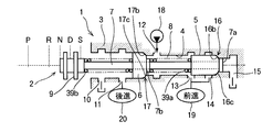
- FIG. 1 schematically shows an example of a manual valve 1 configured to select these positions or ranges.
- the example shown here is an example of a so-called spool type valve, and the valve body 2 is inserted into a cylinder portion 4 formed in the valve body 3 so as to move back and forth in the axial direction thereof.
- the valve body 2 includes cylindrical or disk-like land portions 5 and 6 at two positions, a tip portion and an intermediate portion, and these land portions 5 and 6 are integrally connected by a shaft portion 7. Yes. Therefore, a portion between the land portions 5 and 6 is a bulge portion 8 having a smaller diameter than the land portions 5 and 6.
- the shaft portion 7 extends toward the rear end portion and protrudes from the cylinder portion 4 to the outside.
- the protruding end portion applies an operating force in the axial direction to the valve body 2 to provide the valve body 2.
- the operation unit 9 is used to move the lever back and forth.
- the operation unit 9 is configured to connect a linkage connected to a shift lever (not shown) or to connect an electrically operated shift actuator.
- the cylinder portion 4 is a hollow portion formed in a metal valve body 3 such as aluminum or aluminum alloy and having one end opened, and is substantially half on the opening end side (substantially left half in FIG. 1). Is formed in a cylindrical shape substantially equal to the outer diameter of one land portion 6 described above, and substantially half of the tip side (substantially right half in FIG. 1) has a cylindrical shape substantially equal to that of the other land portion 5. .
- six ports 10, 11, 12, 13, 14, 15 are formed so as to open on the inner peripheral surface of the cylinder portion 4. These port portions are a first drain port 10, a reverse port 11, an input port 12, a first forward port 13, a second forward port 14, and a second drain port 15 from the left side of FIG. 1. ing.
- Each of the ports 10 to 15 is constituted by an annular groove having a narrower width than the land portions 5 and 6 and an oil hole opened in the annular groove.
- the interval between these ports 10 to 15 is set to an interval at which the communication state described below is established. That is, in the example shown in FIG. 1, the parking position P, the reverse position R, the neutral position N, and the drive position D described above are set in order from the left side of FIG.
- the input port 12 is moved to close the input port 12, and the intermediate land portion 6 moves to the vicinity of the opening end of the cylinder portion 4.
- the reverse port 11 communicates with the first drain port 10.
- the forward ports 13 and 14 communicate with the second drain port 15.
- the land portion 5 on the front end side moves to a position where the first advance port 13 is closed and the second advance port 14 is opened, and therefore the second advance port 14 is moved to the second position.
- the intermediate land portion 6 is located between the first drain port 10 and the reverse port 11 so that the input port 12 and the reverse port 11 are connected to the valley portion. 8 to communicate.
- the land portion 5 on the front end side closes the first advance port 13 and the second advance port 14 in half, so that the second advance port 14 is connected to the second drain port 15.
- the intermediate land portion 6 passes through the reverse port 11 and opens a part thereof to the first drain port 10 side to connect the reverse port 11 to the first drain port 10. . Therefore, although the input port 12 opens to the valley section 8, it does not communicate with any other port.
- valve body 2 In the drive position D, the valve body 2 further moves to the right in FIG. 1, and the land portion 5 on the front end side closes the second advance port 14 and closes the first advance port 14 half, and therefore 1 forward port 13 communicates with the input port 12 via the burry portion 8, while the intermediate land portion 6 passes through the reverse port 11 and blocks the reverse port 11 from the input port 12. And communicate with the first drain port 10.
- the switching valve 1 shown in FIG. 1 is provided with seal portions 16 and 17 for sealing between the portions on both sides in the axial direction across the land portions 5 and 6 at the drive position D. It has been.
- the seal portion 16 for the land portion 5 on the front end side will be described.
- a ring-shaped packing 16 a having an outer diameter substantially equal to the outer diameter of the land portion 5 is attached to the front end surface of the land portion 5.
- the contact part in this invention is formed.
- An annular protrusion that protrudes toward the inner periphery of the inner peripheral surface of the cylinder portion 4 between the second forward port 14 and the second drain port 15 so that the inner diameter is smaller than the packing 16a.
- the protrusion part is the valve seat part 16b.
- the seal portion 16 is formed between the land portion 5 and the inner peripheral surface of the cylinder portion 4 by the packing 16a provided on the tip surface of the land portion 5 being in contact with the valve seat portion 16b. Sealed in a liquid-tight state, and as a result, sealed between the portions on both sides in the axial direction with respect to the land portion 5 (space portions on each end face side in the axial direction of the land portion 5). Is configured to do.
- the seal portion 17 for the land portion 6 in the intermediate portion is configured in substantially the same manner as the seal portion 16 for the land portion 5 on the tip side, and the tip surface of the land portion 6 (the right side in FIG. 1).
- a ring-shaped packing 17a having an outer diameter substantially equal to the outer diameter of the land portion 6 is attached to the end surface of the land portion 6 and an abutting portion according to the present invention is formed.
- an annular projecting portion projecting toward the inner peripheral side is formed between the reverse port 11 and the input port 12 on the inner peripheral surface of the cylinder portion 4 so that the inner diameter is smaller than the packing 17a.
- the protruding portion is a valve seat portion 17b.
- the seal portion 17 is formed between the land portion 6 and the inner peripheral surface of the cylinder portion 4 by the packing 17a provided on the front end surface of the land portion 6 being in contact with and intimate contact with the valve seat portion 17b. Sealed in a liquid-tight state, and as a result, sealed between the portions on both sides in the axial direction with respect to the land portion 6 (space portions on each end face side in the axial direction of the land portion 6). Is configured to do. Therefore, the outer diameter of the land portion 5 on the front end side is smaller than the outer diameter of the land portion 6 in the intermediate portion, and the inner diameter of the cylinder portion 4 correspondingly increases at the opening end side on the left side in FIG. It is smaller on the closed end side on the right side.
- the hydraulic pressure source 18 is communicated with the input port 12, the forward actuator 19 is communicated with the forward ports 13 and 14, and the reverse actuator 20 is communicated with the reverse port 11.
- These actuators 19 and 20 are incorporated in the power train of the vehicle, and operate by being supplied with hydraulic pressure to set the power transmission path of the power train so that the vehicle travels forward or backward. belongs to.
- the actuators 19 and 20 are clutches that connect the rotating elements or connect the rotating elements to a predetermined fixed portion in a stepped automatic transmission mainly composed of a plurality of sets of planetary gear mechanisms.
- a hydraulic actuator for engaging a forward clutch and a reverse brake in the forward / reverse switching mechanism, and a plurality of forward In a dual clutch automatic transmission (DCT) configured to select a gear pair to transmit torque from among gear pairs provided for each stage and each reverse stage, the synchronizers are used. It is a hydraulic actuator for shift for operating.
- DCT dual clutch automatic transmission
- FIG. 2 schematically shows an example of a vehicle power train in which the forward / reverse switching mechanism 21 is arranged in series with the continuously variable transmission mechanism 22, and torque is applied to the output side of the engine 23 that is a driving force source.
- the converter 24 is connected, and the output member of the torque converter 24 is connected to the forward / reverse switching mechanism 21.
- the forward / reverse switching mechanism 21 is mainly composed of a single pinion type planetary gear mechanism. That is, the forward / reverse switching mechanism 21 has a sun gear 25, a ring gear 26 disposed concentrically with the sun gear 25, and a carrier 27 holding the sun gear 25 and a pinion gear that rotates in mesh with the ring gear 26.
- the ring gear 26 is connected to the output member of the torque converter 24 as an input element, and the sun gear 25 is connected to the input member of the continuously variable transmission mechanism 22 as an output element.
- the carrier 27 is connected to a brake 28 that is engaged by the reverse actuator 20, and the carrier 27 is a reaction force element. Further, a clutch 29 that is engaged by the forward actuator 19 and connects the sun gear 25 and the ring gear 26 is provided.
- the output member of the continuously variable transmission mechanism 22 is connected to the left and right drive wheels 31 via the differential 30.
- the brake 28 and the clutch 29 correspond to the engagement device in the present invention.
- the entire planetary gear mechanism rotates as a whole when the clutch 29 is engaged to set the forward movement state, and the brake 28 is engaged and the carrier 27 is engaged. Is fixed so that the sun gear 25, which is an output element, rotates in the opposite direction to the ring gear 26, which is an input element, and sets a reverse state.
- a mechanism for supplying or discharging hydraulic pressure to the hydraulic power source 18 and the actuators 19 and 20 will be described later.
- the input port 12 is closed by the land portion 5 on the front end side, and the reverse port 11 is connected to the first drain port 10.
- the advance port 13, 14 communicates with the second drain port 15 and is exhausted from the forward actuator 19 while being communicated and exhausted from the reverse actuator 20. Therefore, these actuators 19 and 20 are in a non-operating state, and the power train does not transmit torque, so that torque is not transmitted to the drive wheels 31.
- a lock mechanism that stops the rotation of the output shaft of the speed change mechanism operates to stop the rotation of the drive wheels 31.
- the second forward port 14 communicates with the second drain port 15 and is discharged from the forward actuator 19.
- the reverse port 11 communicates with the input port 12 via the burry portion 8 in the valve body 2. Accordingly, the hydraulic pressure is supplied to the reverse actuator 20, and the brake 28 shown in FIG. 2, for example, is engaged, and the reverse state is set. In this case, if a slight gap is provided between the valve body 2 and the cylinder portion 4 to ensure smooth back-and-forth movement of the valve body 2, the pressure oil can leak even slightly. However, since the time required for the vehicle to travel backward is short, there is little energy loss due to leakage of pressure oil, and there is no particular problem.
- the second forward port 14 is communicated with the second drain port 15 and the reverse port 11 is communicated with the first drain port 10 as described above. Accordingly, the pressure is discharged from the actuators 19 and 20 so that the actuators 19 and 20 are not operated, so that the power train does not transmit torque and the torque is not transmitted to the drive wheels 31.
- the valve body 2 moves to the position shown in FIG. 1, and the packings 16a and 17a provided in the land portions 5 and 6 are provided corresponding to the respective valve portions. It is pressed against the seats 16b and 17b. That is, between each land part 5 and 6 and the cylinder part 4 is sealed in a liquid-tight state by each seal part 16 and 17, and as a result, the valley part 8 partitioned by these land parts 5 and 6 is formed. It is sealed with respect to other parts inside the cylinder part 4. Further, as described above, the land portion 5 on the front end side closes the second advance port 14 and closes the first advance port 14 in half, so that the first advance port 13 is connected to the input port 12.
- the intermediate land portion 6 passes through the reverse port 11 to block the reverse port 11 from the input port 12 and to communicate with the first drain port 10. Accordingly, the hydraulic pressure is supplied to the forward actuator 19 and discharged from the reverse actuator 20. As a result, in the example shown in FIG. 2, for example, the clutch 29 is engaged and the brake 28 is released, so that the forward movement state is set. In this case, since the seal portions 16 and 17 are closed in a liquid-tight state, the valve body 2 is smoothly moved between the outer peripheral surfaces of the land portions 5 and 6 and the inner peripheral surface of the cylinder portion 4. Even when a slight gap is provided, the portions on both sides in the axial direction across the land portions 5 and 6 are blocked in a liquid-tight state.
- the valley portion 8 between the two land portions 5 and 6 is blocked in a liquid-tight state with respect to the drain ports 10 and 15 and the reverse port 11. Therefore, the pressure oil supplied from the hydraulic power source 18 to the forward actuator 19 does not leak, and pressure loss or energy loss during forward traveling can be avoided or suppressed. Further, if the oil passage communicating with the input port 12 is shut off, the hydraulic pressure can be confined to the forward actuator 19, so there is no need to continue to supply the hydraulic pressure for maintaining the forward traveling state. In this case, energy consumption can be avoided or suppressed.
- the hydraulic pressure source 18 includes a pump 32 driven by the engine 23 or a motor (not shown), and an accumulator 34 connected to a discharge port of the pump 32 via a check valve 33.
- An oil path 35 communicating with the accumulator 34 and the input port 12 of the manual valve 1 is electrically controlled to open the oil path 35 and to close the oil path 35 in a liquid-tight state.
- a supply valve 36 that is a two-way valve that switches to a state is interposed.
- the input port 12 is electrically controlled to have an open state in which the input port 12 communicates with a predetermined drain location, and a closed state in which the input port 12 is sealed in a liquid tight state with respect to the drain location.
- An exhaust pressure valve 37 that is a two-way valve that switches to is communicated.
- the hydraulic pressure generated by the pump 32 or the accumulator 34 is stored by controlling the supply valve 36 to the open state with the manual valve 1 set to the drive position D.
- the hydraulic pressure is supplied to the forward actuator 19 and the clutch 29 is engaged to set the forward state.
- the exhaust pressure valve 37 is controlled to be in the open state, the forward actuator 19 communicates with a predetermined drain location and is exhausted from the forward actuator 19, so that the transmission torque capacity of the clutch 29 decreases or the clutch 29 is released. That is, the engagement / release of the clutch 29 can be controlled by these valves 36 and 37, and the transmission torque capacity can be controlled.
- valves 36 and 37 are set in a closed state while a predetermined hydraulic pressure is supplied to the forward actuator 19, the hydraulic pressure is confined in the forward actuator 19 to maintain the engaged state of the clutch 29 or the transmission torque capacity. can do. That is, the closing control is possible.
- the supply valve 36 to the open state with the reverse position R selected by the manual valve 1
- the hydraulic pressure generated by the pump 32 or the hydraulic pressure stored in the accumulator 34 is supplied to the reverse actuator 20.
- the brake 28 is engaged, and the reverse drive state is set.
- the exhaust pressure valve 37 is controlled to be in the open state
- the reverse actuator 20 is communicated with a predetermined drain location and is exhausted from the reverse actuator 20, so that the transmission torque capacity of the brake 28 decreases or the brake 28 is released. That is, the engagement / release of the brake 28 can be controlled by these valves 36 and 37, and the transmission torque capacity thereof can be controlled.
- valve seat part and the contact part in the present invention may be of any configuration as long as the valve body 2 moves in the axial direction and can be in close contact with each other and sealed in a liquid-tight state. It is not limited to the configuration using 16a, and may be another appropriate configuration.
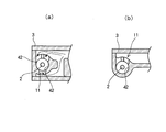
- a taper surface is formed on the outer peripheral portion on one end side in the axial direction of the land portions 5 and 6 and this is used as a contact portion, and the inner peripheral end of the annular projecting portion formed on the inner peripheral surface of the cylinder portion 4 is It is good also as a taper shape and setting it as a valve seat part here. Or as shown in FIG.
- each valve seat part 16b, 17b is formed so that an inner peripheral surface may become a taper surface, and it is the axial direction of each land part 5, 6 facing each valve seat part 16b, 17b.
- Convex-curved contact portions 16c and 17c are formed on one end face, and the contact portions 16c and 17c are brought into contact with the tapered valve seat portions 16b and 17b to be sealed in a liquid-tight state.
- the seal portions 16 and 17 may be configured as described above.
- the shift device may be configured to select a position B (or S) that limits the speed ratio on the side.
- the present invention can be configured to be suitable for such a shift device, an example of which is shown in FIGS.
- FIG. 5 is an example in which the shaft portion 7 can be moved relative to the land portions 5 and 6 having the configuration shown in FIG. 1 described above. That is, the shaft portion 7 passes through the land portions 5 and 6 along the central axis thereof, and a flange portion 7a serving as a stopper for preventing the shaft portion 7 is formed at the tip portion.
- a cylindrical spacer 38 penetrating the shaft portion 7 is disposed between the land portions 5 and 6, and the space between the land portions 5 and 6 is maintained at a constant interval by the spacer 38. Yes. Further, a compression coil spring 39 is disposed between the land portion 6 at the intermediate portion and the operation portion 9 described above, and the land portion 6 is pressed toward the distal end side of the shaft portion 7.
- the compression is performed in a state until a load that positively compresses the compression coil spring 39 is applied, that is, in a state where any one of the parking position P or the drive position D is selected.
- the land portions 5 and 6 and the spacer 38 are pressed toward the distal end side of the shaft portion 7 by the elastic force of the coil spring 39, and the land portion 5 on the distal end side comes into contact with the flange portion 7a formed on the shaft portion 7. Yes. That is, the positions of the land portions 5 and 6 with respect to the shaft portion 7 are determined at predetermined positions by the flange portion 7 a and the spacer 38. Therefore, as shown in FIG.
- a position B (hereinafter, tentatively referred to as a brake position) B that limits engine braking or setting a high speed gear ratio is provided adjacent to the drive position D, and the shaft portion of the valve body 2 7 is further moved from the drive position D to the front end side (right side in FIG. 5).
- the state is shown in FIG. 5 (b).
- the land portions 5 and 6 are stopped from being advanced by the valve seat portions 16b and 17b which are the limit positions, whereas the shaft portion 7 is connected to each land. 5 passes through the portions 5 and 6 and the spacer 38 and moves forward in the right direction in FIG. 5 to reach the position set as the brake position B. In that case, since the land portions 5 and 6 do not move, the communication state of each port does not change. It is detected that the position B is selected, and an appropriate actuator (not shown) for operating the engine brake or limiting the speed ratio on the high speed side is operated based on the detection result.
- the example shown in FIG. 6 is an example in which the shaft portion 7 can be moved relative to the land portions 5 and 6 having the configuration shown in FIG. 4 described above. That is, the shaft portion 7 passes through the land portions 5 and 6 along the center axis, and a flange portion 7a for preventing the shaft portion 7 is formed at the tip portion. Further, a stopper 7 b for determining the position of the land portion 6 is provided at the intermediate portion of the shaft portion 7.
- a compression coil spring 39a is disposed between the stopper 7b and the land portion 5 on the front end side, and a compression coil spring 39b is disposed between the land portion 6 at the intermediate portion and the operation portion 9 described above. Therefore, the land portion 5 on the front end side is pressed toward the flange portion 7a by the compression coil spring 39a, and the land portion 6 at the intermediate portion is pressed toward the stopper 7b by the other compression coil spring 39b. .
- a position (hereinafter temporarily referred to as a sub-position) S that applies engine braking or restricts the setting of the high speed side gear ratio is provided adjacent to the drive position D, and the shaft portion of the valve body 2 7 is further moved from the drive position D to the tip side.
- the land portions 5 and 6 are prevented from advancing by the valve seat portions 16b and 17b, whereas the shaft portion 7 passes through the land portions 5 and 6 in the right direction in FIG.
- the vehicle moves forward and reaches the position set as the sub-position S. In that case, since the land portions 5 and 6 do not move, the communication state of each port does not change. It is detected that the position S has been selected, and an appropriate actuator (not shown) for operating the engine brake or limiting the speed ratio on the high speed side is operated based on the detection result.
- the shaft portion 7 when the shaft portion 7 is configured to move relative to the land portions 5 and 6, the shaft even if the movement of the land portions 5 and 6 is restricted by the seal portions 16 and 17.
- the part 7 can be moved further.
- the arrangement of the positions P, N, R, and D can be reversed from the arrangement shown in FIG. 1 or FIG. An example of this is shown in FIG.
- the configuration shown in FIG. 5 is partially changed, and the drive position D, neutral position N, reverse position R, and parking position P are set in order from the left in FIG. Has been.
- the first drain port 10A, the forward port 11A, the input port 12A, the first reverse port 13A, the second port are sequentially arranged from the left in FIG.
- a reverse port 14A and a second drain port 15A are provided.
- the input port 12A is supplied with hydraulic pressure from a hydraulic pressure source 18 and discharges the hydraulic pressure to a predetermined drain location.
- a forward actuator 19 is communicated with the forward port 11A, and a reverse actuator 20 is communicated with the reverse ports 13A, 14A.
- the interval or position between these ports 10A to 15A is set so that the communication state described below is established. That is, at the drive position D, the intermediate land portion 6 is located between the first drain port 10A and the forward port 11A so that the input port 12 and the forward port 11A communicate with each other, The land portion 5 is located between the input port 12 and the first reverse port 13A so that the reverse ports 13A and 14A are blocked from the input port 12, and the second reverse port 14A is the second reverse port 14A. To the drain port 15A. This state is shown in FIG. In this drive position D, the packings 16a and 17a provided on the land portions 5 and 6 are separated from the valve seat portions 16b and 17b, and the seal portions 16 and 17 are not closed.
- the intermediate land portion 6 moves to a position where the forward port 11A is opened to the first drain port 10A side, and the forward port 11A communicates with the first drain port 10A.
- the land portion 5 on the front end side closes the first reverse port 13A and moves the second reverse port 14A to the position where the second reverse port 14A is opened to the second drain port 15A side. To the drain port 15A.
- the land portion 5 on the tip side opens the first reverse port 13A to the input port 12A side and closes the second reverse port 14A, and the packing 16a provided on the land portion 5
- the seal portion 16 is closed in a liquid-tight state by contacting the valve seat portion 16b.
- the land portion 6 in the intermediate portion moves between the forward port 11A and the input port 12A to shut off these ports 11A and 12A, and at the same time, the packing 17a provided in the land portion 6 Comes into contact with the valve seat portion 17b and the seal portion 17 is closed in a liquid-tight state.
- the input port 12A and the reverse port 14A communicate with each other via the burry unit 8, and at the same time, the burry unit 8 is sealed in a liquid-tight state with respect to the other ports. Therefore, in the reverse drive state, the leakage of the pressure oil at the manual valve 1 is avoided or suppressed, and so-called hydraulic pressure closing control is possible. This state is shown in FIG.
- the shaft portion 7 is further moved in the right direction in FIG. In that case, since the movement of the land portions 5 and 6 is blocked by the valve seat portions 16b and 17b, the communication state of each port in the manual valve 1 does not change.
- the shaft portion 7 and a shift lever for operating the shaft 7 or appropriate actuators move to a position corresponding to the parking position P. Therefore, the parking state is controlled by detecting the position. .
- the discharge valve 37 shown in FIG. 3 is controlled to be opened and discharged from the reverse actuator 20, and at the same time, an appropriate lock mechanism (not shown) is operated to stop the rotation of the drive wheels 31.
- the seal part in this invention can be comprised by the seal ring which slidably contacts the internal peripheral surface of the cylinder part 4 in the liquid-tight state other than the structure which closes a packing closely to a valve seat part and closes it in a liquid-tight state.
- An example is shown in FIG.
- the example shown here is an example in which the configuration of the seal portion and each port in the configuration shown in FIG. 1 is changed. Therefore, the same or common configuration as the configuration shown in FIG. The same reference numerals are given.
- the outer diameter of the cylinder part 4 is constant over the entire length.
- Annular grooves are formed in the outer peripheral parts of the land parts 5 and 6, and seal rings 40 and 41 are fitted in the annular grooves. These seal rings 40 and 41 are slidably contacted with the inner peripheral surface of the cylinder portion 4 by their own elastic force in a liquid-tight state, and are in close contact with the inner side wall of the annular groove, whereby the outer peripheral surfaces of the land portions 5 and 6 are provided. And the inner peripheral surface of the cylinder portion 4 are sealed in a liquid-tight state.
- each of the ports 10 to 15 is configured such that when the seal rings 40 and 41 together with the valve body 2 move in the axial direction, the seal rings 40 and 41 are not caught at the open ends.
- an outer diameter restricting portion is provided that restricts the outer diameter of the seal rings 40, 41 so as not to increase beyond the inner diameter of the cylinder portion 4 by contacting the outer peripheral surfaces of the seal rings 40, 41.
- An example thereof is shown in FIG. 9, and in the example shown in FIG. 9A, each port (representing the reverse port 11 as a representative example) does not have the above-described annular groove, and FIG. 9 (a) is formed as an opening hole that opens at two places at the top and one place at the bottom.
- the remaining portion in the circumferential direction excluding these opening holes is an outer diameter restricting portion 42 that contacts at least two locations facing each other in the diameter direction of the seal rings 40 and 41.
- the example shown in (b) is formed as an opening hole that opens at two places on the upper part thereof.
- the range in which the opening holes shown in (b) of FIG. 9 are provided is a range in which the opening angle with respect to the center portion of the valve body 2 is smaller than 180 degrees, and therefore these opening holes are excluded.
- the remaining portion in the circumferential direction serves as an outer diameter restricting portion 42 that contacts at least two locations facing each other in the diameter direction of the seal rings 40 and 41.
- seal rings 40 and 41 will be further described.
- These seal rings 40 and 41 may be made of a flexible elastic material or made of a hard material. If it is formed of a soft material or is formed in an annular shape that is partially cut away by a hard material, it is elastically expanded so that the inner diameter is equal to or greater than the outer diameter of the land portions 5 and 6. Then, it can be assembled to the land portions 5 and 6 by fitting in the annular grooves of the land portions 5 and 6 in this state.
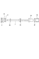
- the land portions 5 and 6 are divided and the seal rings 40 and 41 are assembled between the divided pieces. It is preferable. An example thereof is shown in FIG.
- the land portion 5 on the front end side is formed from a flange portion and a boss portion having an outer diameter approximately equal to the inner diameter of the seal ring 40 and extending from the flange portion to the tip of the shaft portion 7.
- the base portion 5 ⁇ / b> A is integrated with the shaft portion 7. Moreover, it is fitted with the boss
- the ring material 5B which forms an annular groove between the flange parts in 5 A of bases is provided. Therefore, after the seal ring 40 is fitted into the boss portion of the base portion 5A, the ring member 5B is attached to the boss portion by a method such as press fitting or shrink fitting, thereby configuring the land portion 5 in a state where the seal ring 40 is fitted. can do.
- the land portion 6 at the intermediate portion has an outer diameter approximately equal to the inner diameter of the flange portion and the seal ring 41 and is directed from the flange portion toward the operation portion 9 side of the shaft portion 7 in the same manner as the land portion 5 at the front end side.
- a base portion 6 ⁇ / b> A composed of a boss portion extending in the direction is provided, and the base portion 6 ⁇ / b> A is integrated with the shaft portion 7. Moreover, it is fitted with the boss
- the operation portion 9 is configured to be detachable from the shaft portion 7, and a stopper piece 9A having an outer diameter smaller than the inner diameter of the seal ring 41 and the ring material 6B is provided on the end portion side of the shaft portion 7 to operate the operation portion 9.
- the operation portion 9 is fixed to the shaft portion 7 by a method such as caulking. Therefore, after the seal ring 41 is fed from one end side (left end side in FIG. 10) of the shaft portion 7 and fitted into the boss portion of the base portion 6A, the ring material 6B is pressed into the boss portion by a method such as press fitting or shrink fitting. By attaching, the land part 6 in the state where the seal ring 41 is fitted can be formed.
- the present invention is not limited to the specific examples described above, and the number of land portions provided in the valve body may be one, or three or more. Moreover, in this invention, you may provide two or more seal rings in each land part.
Landscapes
- Engineering & Computer Science (AREA)
- General Engineering & Computer Science (AREA)
- Mechanical Engineering (AREA)
- Control Of Transmission Device (AREA)
- Multiple-Way Valves (AREA)
- Gear-Shifting Mechanisms (AREA)
- Sliding Valves (AREA)
Abstract
Description
Claims (11)
- 手動操作に基づいて軸線方向に前後動する弁体に複数のランド部とそれらのランド部の間のバリー部とが形成され、その弁体が前後動自在に挿入されたシリンダ部に複数のポート部が開口して設けられ、弁体の軸線方向での位置に応じて、所定のポート部同士が前記バリー部を介して連通され、もしくは前記ランド部によって遮断されるように構成された切替バルブにおいて、
いずれかのランド部を挟んだ軸線方向での両側の部分の間を液密状態に封止するシール部を備えていることを特徴とする切替バルブ。 - 前記バリー部を区画している二つのランド部のそれぞれに前記シール部が設けられ、
一方のシール部が該一方のシール部の設けられている一方のランド部と前記シリンダ部との間を液密状態に封止した状態では、他方のシール部が該他方のシール部の設けられている他方のランド部と前記シリンダ部との間を液密状態に封止するように構成されている
ことを特徴とする請求項1に記載の切替バルブ。 - 前記各シール部が前記各ランド部と前記シリンダ部との間を液密状態に封止している状態で前記バリー部に開口する入力ポートと出力ポートとを更に備えていることを特徴とする請求項2に記載の切替バルブ。
- 前記入力ポートに油圧源が接続され、かつ
前記周力ポートに車両の前進用係合装置もしくは後進用係合装置が接続されている
ことを特徴とする請求項3に記載の切替バルブ。 - 前記ポート部は、車両の前進用係合装置もしくは後進用係合装置に油圧を供給する出力ポートと、油圧源の油圧を導入する入力ポートとを含み、
前記ランド部は、前記入力ポートと前記出力ポートとを共に開口させるバリー部を区画する二つのランド部を含み、
前記シール部は、前記入力ポートと前記出力ポートとを共に前記バリー部に開口させている状態で前記二つのランド部と前記シリンダ部との間を液密状態に封止するように構成されている
ことを特徴とする請求項1に記載の切替バルブ。 - 前記シール部は、
前記シリンダ部の内周面からそのシリンダ部の中心部に向けて突出した環状の弁座部と、
前記弁体が軸線方向に移動した際にその弁座部に押し付けられて液密状態に密着する、前記ランド部に形成された当接部と
を備えていることを特徴とする請求項1ないし5のいずれか一項に記載の切替バルブ。 - 前記弁座部は、弾性素材からなるリング状部材によって構成されていることを特徴とする請求項6に記載の切替バルブ。
- 前記弁座部および前記当接部とは、互いに密着するテーパ面をそれぞれ備えていることを特徴とする請求項6または7に記載の切替バルブ。
- 前記弁体は、前記ランド部が取り付けられかつランド部に対して軸線方向に相対移動可能なシャフト部を備え、
前記ランド部は前記シャフト部における所定の限界位置から軸線方向での一方向に移動可能であり、かつ前記限界位置から他の方向には移動できないように前記シャフト部に取り付けられている
ことを特徴とする請求項1ないし8のいずれか一項に記載の切替バルブ。 - 前記シール部は、外径を増大させるように作用する弾性力で前記シリンダ部の内周面に液密状態に接触するシールリングを含み、
前記ポート部は、前記シールリングの外周面のうち直径方向で対向する少なくとも二箇所に接触して前記シールリングの外径を前記シリンダ部の内径以下に維持する外径規制部を備えている
ことを特徴とする請求項1ないし5のいずれか一項に記載の切替バルブ。 - 前記出力ポートは、前記前進用係合装置に連通した前進用ポートと、前記後進用係合装置に連通した後進用ポートとを含み、
前記シール部は、前記前進用ポートと前記後進用ポートとのいずれか一方と前記入力ポートとを共に前記バリー部に開口させている状態で前記二つのランド部と前記シリンダ部との間を液密状態に封止するように構成され、
前記弁体は、前記前進用ポートと前記入力ポートとを共に前記バリー部に開口させた位置と、前記後進用ポートと前記入力ポートとを共に前記バリー部に開口させた位置とに移動させられるように構成され、
前記入力ポートには、その入力ポートを油圧源に連通させ、また油圧源に対して遮断する供給弁と、前記入力ポートをドレイン箇所に連通させ、またドレイン箇所に対して遮断する排出弁とを有する給排油路が連通させられている
ことを特徴とする請求項3または5ないし10のいずれか一項に記載の切替バルブ。
Priority Applications (8)
| Application Number | Priority Date | Filing Date | Title |
|---|---|---|---|
| US14/236,783 US9297462B2 (en) | 2011-08-03 | 2011-08-03 | Switch valve |
| AU2011374411A AU2011374411B2 (en) | 2011-08-03 | 2011-08-03 | Switching valve |
| JP2013526684A JP5708808B2 (ja) | 2011-08-03 | 2011-08-03 | 切替バルブ |
| BR112014002571A BR112014002571A2 (pt) | 2011-08-03 | 2011-08-03 | válvula de comutação |
| RU2014103491/06A RU2556149C1 (ru) | 2011-08-03 | 2011-08-03 | Переключающий клапан |
| PCT/JP2011/067732 WO2013018203A1 (ja) | 2011-08-03 | 2011-08-03 | 切替バルブ |
| EP11870348.7A EP2740977B1 (en) | 2011-08-03 | 2011-08-03 | Switching valve |
| CN201180072707.8A CN103717952B (zh) | 2011-08-03 | 2011-08-03 | 换向阀 |
Applications Claiming Priority (1)
| Application Number | Priority Date | Filing Date | Title |
|---|---|---|---|
| PCT/JP2011/067732 WO2013018203A1 (ja) | 2011-08-03 | 2011-08-03 | 切替バルブ |
Publications (1)
| Publication Number | Publication Date |
|---|---|
| WO2013018203A1 true WO2013018203A1 (ja) | 2013-02-07 |
Family
ID=47628766
Family Applications (1)
| Application Number | Title | Priority Date | Filing Date |
|---|---|---|---|
| PCT/JP2011/067732 WO2013018203A1 (ja) | 2011-08-03 | 2011-08-03 | 切替バルブ |
Country Status (8)
| Country | Link |
|---|---|
| US (1) | US9297462B2 (ja) |
| EP (1) | EP2740977B1 (ja) |
| JP (1) | JP5708808B2 (ja) |
| CN (1) | CN103717952B (ja) |
| AU (1) | AU2011374411B2 (ja) |
| BR (1) | BR112014002571A2 (ja) |
| RU (1) | RU2556149C1 (ja) |
| WO (1) | WO2013018203A1 (ja) |
Cited By (1)
| Publication number | Priority date | Publication date | Assignee | Title |
|---|---|---|---|---|
| WO2015042514A3 (en) * | 2013-09-22 | 2015-07-02 | Unison Industries, Llc | Dual seated by-pass valve for surface coolers |
Families Citing this family (14)
| Publication number | Priority date | Publication date | Assignee | Title |
|---|---|---|---|---|
| US9982511B2 (en) | 2014-01-03 | 2018-05-29 | Proserv Operations, Inc. | Dirty fluid pressure regulator and control valve |
| US10670155B2 (en) | 2015-10-05 | 2020-06-02 | Proserv Gilmore Valve Llc | Latching poppet valve |
| US10487951B2 (en) * | 2016-01-22 | 2019-11-26 | Proserv Operations, Inc. | Non-interflow directional control valve |
| US10591076B2 (en) | 2016-09-15 | 2020-03-17 | Proserv Operations, Inc. | Low friction hydraulic circuit control components |
| US10739796B2 (en) | 2017-09-22 | 2020-08-11 | Proserv Gilmore Valve Llc | Pressure regulator with reconfigurable hydraulic dampening |
| US10633951B2 (en) | 2017-09-22 | 2020-04-28 | Proserv Operations, Inc. | Pressure regulator with user selectable dampening |
| DE102017219645A1 (de) * | 2017-11-06 | 2019-05-09 | Zf Friedrichshafen Ag | Ventil, Hydrauliksystem und Kraftfahrzeuggetriebe |
| US11022226B2 (en) | 2018-03-20 | 2021-06-01 | Proserv Operations, Inc. | Microfluidic valve |
| US11054050B2 (en) | 2018-08-13 | 2021-07-06 | Proserv Operations Inc. | Valve with press-fit insert |
| US11686330B2 (en) * | 2018-09-20 | 2023-06-27 | The Boeing Company | Manufacture and process for inhibiting wear in a latch system |
| US11209096B2 (en) | 2018-11-19 | 2021-12-28 | Proserv Operations, Inc. | Bilateral and throttling directional control valve |
| JP7357465B2 (ja) * | 2019-05-22 | 2023-10-06 | 川崎重工業株式会社 | 油圧システム |
| US11261982B2 (en) | 2019-06-27 | 2022-03-01 | Proserv Gilmore Valve Llc | Pressure relief valve with bi-directional seat |
| US11828370B2 (en) | 2020-01-02 | 2023-11-28 | Proserv Gilmore Valve Llc | Check valve with conforming seat |
Citations (6)
| Publication number | Priority date | Publication date | Assignee | Title |
|---|---|---|---|---|
| JPS5022322A (ja) * | 1973-06-29 | 1975-03-10 | ||
| JPS57117477U (ja) * | 1981-01-16 | 1982-07-21 | ||
| JPS59108870U (ja) * | 1983-01-12 | 1984-07-23 | 焼結金属工業株式会社 | スプ−ル弁 |
| JP2003013909A (ja) * | 2001-06-29 | 2003-01-15 | Bosch Automotive Systems Corp | 油圧回路 |
| JP2005036960A (ja) * | 2003-06-24 | 2005-02-10 | Nachi Fujikoshi Corp | 2速油圧モータの自動変速切換弁 |
| JP2005090635A (ja) | 2003-09-17 | 2005-04-07 | Denso Corp | 自動変速機のシフトポジション検出装置 |
Family Cites Families (15)
| Publication number | Priority date | Publication date | Assignee | Title |
|---|---|---|---|---|
| US2971090A (en) * | 1955-05-16 | 1961-02-07 | Futurecraft Corp | Solenoid operated high pressure valve having minimum closure travel |
| US2837148A (en) | 1956-07-25 | 1958-06-03 | Orenda Engines Ltd | Fuel metering valve |
| FR2265685A1 (en) * | 1974-03-29 | 1975-10-24 | Delabie Sa | Distributor supplying water with adjusted total hardness - with internal sliding plugs and valves |
| SU972178A1 (ru) * | 1979-08-27 | 1982-11-07 | Винницкий политехнический институт | Клапан-переключатель |
| DE3109285A1 (de) * | 1981-03-11 | 1982-09-23 | Cillichemie Ernst Vogelmann Gmbh & Co, 7100 Heilbronn | Absperrvorrichtung |
| US4574687A (en) * | 1982-07-20 | 1986-03-11 | Mannesmann Rexroth Gmbh | Apparatus for positioning an adjusting member |
| JPS6185775U (ja) | 1984-11-12 | 1986-06-05 | ||
| JPH04138167A (ja) | 1990-09-28 | 1992-05-12 | Daikin Ind Ltd | オゾン脱臭機 |
| JPH04138167U (ja) * | 1991-06-17 | 1992-12-24 | エスエムシー株式会社 | 方向切換弁 |
| JP3190447B2 (ja) * | 1992-08-12 | 2001-07-23 | ジヤトコ・トランステクノロジー株式会社 | 自動変速機の制御装置 |
| GB9710529D0 (en) * | 1997-05-23 | 1997-07-16 | Seddon Donald | Hydraulic valves and systems |
| DE19840849C2 (de) * | 1998-09-07 | 2001-09-27 | Claas Industrietechnik Gmbh | Vorrichtung zum Arretieren einer Schaltstange |
| JP4499021B2 (ja) * | 2005-11-17 | 2010-07-07 | トヨタ自動車株式会社 | 車輌用伝動装置 |
| US20070113906A1 (en) * | 2005-11-21 | 2007-05-24 | Sturman Digital Systems, Llc | Pressure balanced spool poppet valves with printed actuator coils |
| KR100748668B1 (ko) * | 2005-12-14 | 2007-08-10 | 현대자동차주식회사 | 자동 변속기 유압 제어시스템의 매뉴얼 밸브 |
-
2011
- 2011-08-03 RU RU2014103491/06A patent/RU2556149C1/ru not_active IP Right Cessation
- 2011-08-03 JP JP2013526684A patent/JP5708808B2/ja not_active Expired - Fee Related
- 2011-08-03 AU AU2011374411A patent/AU2011374411B2/en not_active Ceased
- 2011-08-03 BR BR112014002571A patent/BR112014002571A2/pt not_active Application Discontinuation
- 2011-08-03 EP EP11870348.7A patent/EP2740977B1/en not_active Not-in-force
- 2011-08-03 CN CN201180072707.8A patent/CN103717952B/zh not_active Expired - Fee Related
- 2011-08-03 US US14/236,783 patent/US9297462B2/en not_active Expired - Fee Related
- 2011-08-03 WO PCT/JP2011/067732 patent/WO2013018203A1/ja active Application Filing
Patent Citations (6)
| Publication number | Priority date | Publication date | Assignee | Title |
|---|---|---|---|---|
| JPS5022322A (ja) * | 1973-06-29 | 1975-03-10 | ||
| JPS57117477U (ja) * | 1981-01-16 | 1982-07-21 | ||
| JPS59108870U (ja) * | 1983-01-12 | 1984-07-23 | 焼結金属工業株式会社 | スプ−ル弁 |
| JP2003013909A (ja) * | 2001-06-29 | 2003-01-15 | Bosch Automotive Systems Corp | 油圧回路 |
| JP2005036960A (ja) * | 2003-06-24 | 2005-02-10 | Nachi Fujikoshi Corp | 2速油圧モータの自動変速切換弁 |
| JP2005090635A (ja) | 2003-09-17 | 2005-04-07 | Denso Corp | 自動変速機のシフトポジション検出装置 |
Non-Patent Citations (1)
| Title |
|---|
| See also references of EP2740977A4 |
Cited By (3)
| Publication number | Priority date | Publication date | Assignee | Title |
|---|---|---|---|---|
| WO2015042514A3 (en) * | 2013-09-22 | 2015-07-02 | Unison Industries, Llc | Dual seated by-pass valve for surface coolers |
| US10345057B2 (en) | 2013-09-22 | 2019-07-09 | Unison Industries, Llc | Dual seated by-pass valve for surface coolers |
| US11029103B2 (en) | 2013-09-22 | 2021-06-08 | Unison Industries, Llc | Dual seated by-pass valve for surface coolers |
Also Published As
| Publication number | Publication date |
|---|---|
| AU2011374411B2 (en) | 2015-09-17 |
| AU2011374411A1 (en) | 2014-02-20 |
| EP2740977A4 (en) | 2015-01-28 |
| RU2556149C1 (ru) | 2015-07-10 |
| CN103717952A (zh) | 2014-04-09 |
| JPWO2013018203A1 (ja) | 2015-03-02 |
| EP2740977A1 (en) | 2014-06-11 |
| US9297462B2 (en) | 2016-03-29 |
| BR112014002571A2 (pt) | 2017-02-21 |
| CN103717952B (zh) | 2016-05-04 |
| US20140182722A1 (en) | 2014-07-03 |
| JP5708808B2 (ja) | 2015-04-30 |
| EP2740977B1 (en) | 2017-12-13 |
Similar Documents
| Publication | Publication Date | Title |
|---|---|---|
| JP5708808B2 (ja) | 切替バルブ | |
| US8491434B2 (en) | Transmission assembly having variable force clutch | |
| CN108884934B (zh) | 自动变速器及摩擦接合单元 | |
| CA2578888C (en) | Transmission for vehicle | |
| JP2009287736A (ja) | 無段変速機 | |
| KR100309653B1 (ko) | 동력전환 변속기 특히 2단-유성변속기 | |
| WO2012063522A1 (ja) | ベルト式無段変速機 | |
| JPH0712221A (ja) | 自動変速機の締結力調整装置 | |
| JP5170326B2 (ja) | シール構造 | |
| CN108700136B (zh) | 自动变速器 | |
| KR20100124480A (ko) | 다단 자동 변속기 | |
| KR20000029386A (ko) | 가압 순환장치를 갖는 2속도 지로터 모터 | |
| EP1491798B1 (en) | Traveling transmission of working vehicle | |
| JP4897652B2 (ja) | 歯車変速機のシフト機構 | |
| JP3894439B2 (ja) | 自動変速機用油圧制御装置 | |
| RU2561158C1 (ru) | Уплотнительное устройство для гидравлического контура | |
| JP2009079740A (ja) | 作業機のブレーキ構造 | |
| JP4886720B2 (ja) | 密封装置 | |
| JP3894438B2 (ja) | 自動変速機用油圧制御装置 | |
| JPH05296346A (ja) | 自動変速機の油圧制御装置 | |
| JPS6324008Y2 (ja) | ||
| JP2017067222A (ja) | 自動変速機 | |
| JP2021060053A (ja) | 車両用油圧シリンダ装置 | |
| JP2003139162A (ja) | 密封装置 | |
| JP2020056444A (ja) | 摩擦係合装置 |
Legal Events
| Date | Code | Title | Description |
|---|---|---|---|
| WWE | Wipo information: entry into national phase |
Ref document number: 201180072707.8 Country of ref document: CN |
|
| 121 | Ep: the epo has been informed by wipo that ep was designated in this application |
Ref document number: 11870348 Country of ref document: EP Kind code of ref document: A1 |
|
| ENP | Entry into the national phase |
Ref document number: 2013526684 Country of ref document: JP Kind code of ref document: A |
|
| NENP | Non-entry into the national phase |
Ref country code: DE |
|
| WWE | Wipo information: entry into national phase |
Ref document number: 14236783 Country of ref document: US Ref document number: 2011870348 Country of ref document: EP |
|
| ENP | Entry into the national phase |
Ref document number: 2011374411 Country of ref document: AU Date of ref document: 20110803 Kind code of ref document: A |
|
| ENP | Entry into the national phase |
Ref document number: 2014103491 Country of ref document: RU Kind code of ref document: A |
|
| REG | Reference to national code |
Ref country code: BR Ref legal event code: B01A Ref document number: 112014002571 Country of ref document: BR |
|
| ENP | Entry into the national phase |
Ref document number: 112014002571 Country of ref document: BR Kind code of ref document: A2 Effective date: 20140203 |