WO2013005663A1 - Connecteur de type à levier - Google Patents
Connecteur de type à levier Download PDFInfo
- Publication number
- WO2013005663A1 WO2013005663A1 PCT/JP2012/066653 JP2012066653W WO2013005663A1 WO 2013005663 A1 WO2013005663 A1 WO 2013005663A1 JP 2012066653 W JP2012066653 W JP 2012066653W WO 2013005663 A1 WO2013005663 A1 WO 2013005663A1
- Authority
- WO
- WIPO (PCT)
- Prior art keywords
- connector
- lever
- mounting hole
- locking portion
- contact
- Prior art date
Links
Images


Classifications
-
- H—ELECTRICITY
- H01—ELECTRIC ELEMENTS
- H01R—ELECTRICALLY-CONDUCTIVE CONNECTIONS; STRUCTURAL ASSOCIATIONS OF A PLURALITY OF MUTUALLY-INSULATED ELECTRICAL CONNECTING ELEMENTS; COUPLING DEVICES; CURRENT COLLECTORS
- H01R13/00—Details of coupling devices of the kinds covered by groups H01R12/70 or H01R24/00 - H01R33/00
- H01R13/62—Means for facilitating engagement or disengagement of coupling parts or for holding them in engagement
- H01R13/629—Additional means for facilitating engagement or disengagement of coupling parts, e.g. aligning or guiding means, levers, gas pressure electrical locking indicators, manufacturing tolerances
- H01R13/62933—Comprising exclusively pivoting lever
-
- H—ELECTRICITY
- H01—ELECTRIC ELEMENTS
- H01R—ELECTRICALLY-CONDUCTIVE CONNECTIONS; STRUCTURAL ASSOCIATIONS OF A PLURALITY OF MUTUALLY-INSULATED ELECTRICAL CONNECTING ELEMENTS; COUPLING DEVICES; CURRENT COLLECTORS
- H01R13/00—Details of coupling devices of the kinds covered by groups H01R12/70 or H01R24/00 - H01R33/00
- H01R13/64—Means for preventing incorrect coupling
-
- H—ELECTRICITY
- H01—ELECTRIC ELEMENTS
- H01R—ELECTRICALLY-CONDUCTIVE CONNECTIONS; STRUCTURAL ASSOCIATIONS OF A PLURALITY OF MUTUALLY-INSULATED ELECTRICAL CONNECTING ELEMENTS; COUPLING DEVICES; CURRENT COLLECTORS
- H01R13/00—Details of coupling devices of the kinds covered by groups H01R12/70 or H01R24/00 - H01R33/00
- H01R13/62—Means for facilitating engagement or disengagement of coupling parts or for holding them in engagement
- H01R13/629—Additional means for facilitating engagement or disengagement of coupling parts, e.g. aligning or guiding means, levers, gas pressure electrical locking indicators, manufacturing tolerances
- H01R13/62905—Additional means for facilitating engagement or disengagement of coupling parts, e.g. aligning or guiding means, levers, gas pressure electrical locking indicators, manufacturing tolerances comprising a camming member
- H01R13/62927—Comprising supplementary or additional locking means
-
- H—ELECTRICITY
- H01—ELECTRIC ELEMENTS
- H01R—ELECTRICALLY-CONDUCTIVE CONNECTIONS; STRUCTURAL ASSOCIATIONS OF A PLURALITY OF MUTUALLY-INSULATED ELECTRICAL CONNECTING ELEMENTS; COUPLING DEVICES; CURRENT COLLECTORS
- H01R13/00—Details of coupling devices of the kinds covered by groups H01R12/70 or H01R24/00 - H01R33/00
- H01R13/62—Means for facilitating engagement or disengagement of coupling parts or for holding them in engagement
- H01R13/629—Additional means for facilitating engagement or disengagement of coupling parts, e.g. aligning or guiding means, levers, gas pressure electrical locking indicators, manufacturing tolerances
- H01R13/62933—Comprising exclusively pivoting lever
- H01R13/62955—Pivoting lever comprising supplementary/additional locking means
-
- H—ELECTRICITY
- H01—ELECTRIC ELEMENTS
- H01R—ELECTRICALLY-CONDUCTIVE CONNECTIONS; STRUCTURAL ASSOCIATIONS OF A PLURALITY OF MUTUALLY-INSULATED ELECTRICAL CONNECTING ELEMENTS; COUPLING DEVICES; CURRENT COLLECTORS
- H01R13/00—Details of coupling devices of the kinds covered by groups H01R12/70 or H01R24/00 - H01R33/00
- H01R13/62—Means for facilitating engagement or disengagement of coupling parts or for holding them in engagement
- H01R13/629—Additional means for facilitating engagement or disengagement of coupling parts, e.g. aligning or guiding means, levers, gas pressure electrical locking indicators, manufacturing tolerances
- H01R13/631—Additional means for facilitating engagement or disengagement of coupling parts, e.g. aligning or guiding means, levers, gas pressure electrical locking indicators, manufacturing tolerances for engagement only
-
- H—ELECTRICITY
- H01—ELECTRIC ELEMENTS
- H01R—ELECTRICALLY-CONDUCTIVE CONNECTIONS; STRUCTURAL ASSOCIATIONS OF A PLURALITY OF MUTUALLY-INSULATED ELECTRICAL CONNECTING ELEMENTS; COUPLING DEVICES; CURRENT COLLECTORS
- H01R13/00—Details of coupling devices of the kinds covered by groups H01R12/70 or H01R24/00 - H01R33/00
- H01R13/64—Means for preventing incorrect coupling
- H01R13/641—Means for preventing incorrect coupling by indicating incorrect coupling; by indicating correct or full engagement
-
- H—ELECTRICITY
- H01—ELECTRIC ELEMENTS
- H01R—ELECTRICALLY-CONDUCTIVE CONNECTIONS; STRUCTURAL ASSOCIATIONS OF A PLURALITY OF MUTUALLY-INSULATED ELECTRICAL CONNECTING ELEMENTS; COUPLING DEVICES; CURRENT COLLECTORS
- H01R13/00—Details of coupling devices of the kinds covered by groups H01R12/70 or H01R24/00 - H01R33/00
- H01R13/73—Means for mounting coupling parts to apparatus or structures, e.g. to a wall
- H01R13/74—Means for mounting coupling parts in openings of a panel
Definitions
- the present invention relates to a lever type connector attached to a panel.
- a lever-type connector attached to a panel a first connector, a second connector that can be fitted to the first connector, and a first connector and a second connector that are provided on the first connector and are turned by fitting.
- a lever provided with a mating lever and the first connector and the second connector are fitted in the mounting holes of the panel in a fitted state (see, for example, Patent Document 1).
- the interference portion is provided on the side surface which is the rear side in the rotation direction of the lever, so when the lever is close to the horizontal direction with respect to the fitting direction of the connector, the interference portion and Although the interference with the edge of the mounting hole is reduced, it is difficult to detect the half-fitted state even though the connectors are in a half-fitted state.
- the lever-type connector may be increased in size.
- an object of the present invention is to provide a lever-type connector that can suppress an increase in size and improve detection of a half-fitted state between connectors.
- a lever-type connector that is attached to a mounting hole of a panel, the first connector, the second connector that can be fitted to the first connector, the first connector, and the second connector. And a lever that is provided on one of the connectors and that fits the first connector and the second connector by turning.
- the lever-type connector includes the first connector and the second connector.
- the lever has a locking portion that can be bent inward and outward in the rotational direction, and the one connector is rotated by the lever.
- the locking portion is bent outward in the rotation direction of the lever, and the locking portion is bent inward in the rotation direction of the lever in a properly fitted state of the first connector and the second connector.
- a locking portion that contacts the edge of the mounting hole when the first connector and the second connector are attached to the mounting hole of the panel during the rotation of the lever.
- a lever-type connector provided with a contact portion to be contacted.
- the lever has a locking portion that can be bent inward and outward in the rotation direction, and one connector flexes the locking portion outward in the rotation direction of the lever by the rotation of the lever. Since it has a locked portion that is locked by bending the locking portion inward in the direction of rotation of the lever in the normal fitting state of the first connector and the second connector, the connectors are half-fitted In the combined state, the portion of the lever protruding outward in the rotation direction can be only the locking portion bent by the locked portion, and the increase in size of the lever-type connector can be suppressed.
- such a locking portion has a contact portion that comes into contact with the edge of the mounting hole when the first connector and the second connector are mounted in the mounting hole of the panel during the rotation of the lever. Since the locking part is not bent inward in the direction of rotation of the lever unless the connectors are in a properly fitted state, even if the lever is close to the horizontal direction with respect to the fitting direction of the connector The abutment portion of the locking portion bent outward in the rotation direction of the lever is abutted against the edge portion of the mounting hole, and the half-fitted state between the connectors can be detected.
- the one connector includes a contact enhancement portion that contacts the edge of the mounting hole when the contact portion contacts the edge of the mounting hole. Is provided.
- the half-fitted state between the connectors can also be detected by the contact between the contact-enhancing portion and the edge of the mounting hole. The state detection can be further improved.
- the one connector is restricted from bending outward in the rotational direction of the lever of the locking portion in a properly fitted state of the first connector and the second connector.
- a restricting section to perform.
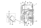
- FIG. 1 is an exploded perspective view of a lever connector according to an embodiment of the present invention.
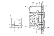
- FIG. 2A is a front view of the lever-type connector according to the embodiment of the present invention.
- FIG. 2B is a side view of the lever-type connector according to the embodiment of the present invention.
- FIG. 3A is a side view of the lever-type connector when the first connector and the second connector of the lever-type connector according to the embodiment of the present invention are in a temporarily locked state.
- 3B is a cross-sectional view of the lever-type connector shown in FIG. 3A.
- FIG. 4A is a side view of the lever-type connector when the first connector and the second connector of the lever-type connector according to the embodiment of the present invention are in a temporarily locked release state.
- FIG. 4B is a cross-sectional view of the lever-type connector shown in FIG. 4A.
- FIG. 5A is a side view of the lever-type connector in a state before the first connector and the second connector of the lever-type connector according to the embodiment of the present invention are properly fitted.
- FIG. 5B is a cross-sectional view of the lever-type connector shown in FIG. 5A.
- FIG. 6A is a side view of the lever-type connector when the first connector and the second connector of the lever-type connector according to the embodiment of the present invention are in a properly fitted state. 6B is a cross-sectional view of the lever-type connector shown in FIG. 6A.
- a lever-type connector according to an embodiment of the present invention will be described with reference to FIGS. 1 to 6B.
- the lever-type connector 1 includes a first connector 3, a second connector 5 that can be fitted to the first connector 3, and a first connector 3 and a first connector 3 that are provided on the first connector 3 and rotated. 2 is provided with a lever 7 for fitting with the connector 5, and the first connector 3 and the second connector 5 are attached to the attachment hole 11 of the panel 9 in a fitted state.
- the lever 7 has a locking portion 13 provided so as to be able to bend inward and outward in the rotation direction.
- the first connector 3 rotates the locking portion 13 in the rotation direction of the lever 7 by the rotation of the lever 7.
- the first connector 3 is provided with a contact enhancing portion 19 that contacts the edge of the mounting hole 11 when the contact portion 17 contacts the edge of the mounting hole 11.
- the first connector 3 is provided with a restricting portion 21 that restricts the bending of the locking portion 13 outward in the rotational direction of the lever 7 in a properly fitted state of the first connector 3 and the second connector 5. ing.
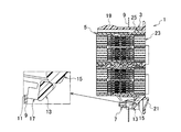
- the first connector 3 includes an inner housing 23 and a frame 25.
- the inner housing 23 has a structure in which two casing members are stacked in two stages, and a plurality of terminals 27 are accommodated therein.
- the inner housing 23 is accommodated in the frame 25.
- the frame 25 accommodates the inner housing 23 inside, and is attached to the attachment hole 11 of the panel 9 by a plurality (four places here) of panel locks 29 provided so as to be elastically deformable outside.
- the inner housing 23 accommodated in the frame 25 is fitted with the second connector 5 in the frame 25.
- the second connector 5 has a structure in which two casing members larger than the inner housing 23 are vertically stacked in two stages, and a plurality of mating terminals 31 connected to a plurality of terminals 27 are accommodated therein. .
- cam followers 35 that are inserted into the cam grooves 33 of the lever 7 project from both side surfaces of the second connector 5.
- the cam follower 35 is inserted into the cam groove 33, and the lever 7 is turned to fit into the inner housing 23, and the plurality of terminals 27 and the plurality of mating terminals 31 are connected.
- the lever 7 is rotatably assembled to the frame 25 by shaft support portions 37 provided on both side surfaces.
- the lever 7 is rotated by pressing the operating portion 39 in a state where the cam follower 35 of the second connector 5 is inserted into the cam groove 33, that is, in a temporarily fitted state of the first connector 3 and the second connector 5.
- the 1st connector 3 and the 2nd connector 5 are made into a regular fitting state by lever action.
- Such a lever 7 is provided with a locking portion 13 that is locked to the locked portion 15 of the frame 25.
- the locking portion 13 is provided on the operation portion 39 side of the lever 7 so as to be able to bend inward and outward in the rotation direction of the lever 7.
- the inside and outside in the rotation direction of the lever 7 indicate the inside and the outside with respect to the locus drawn by the rotation of the lever 7. That is, here, the inward direction of the rotation direction is a direction from the trajectory of rotation of the lever 7 toward the shaft support portion 37, and the outward direction of the rotation direction is a direction away from the trajectory of rotation of the lever 7.
- the locking portion 13 is brought into contact with the locked portion 15 in the second half of the turning operation of the lever 7 and is locked to the locked portion 15 at the end of the turning operation of the lever 7.
- the locked portion 15 protrudes from the lower surface of the frame 25 and is provided with an inclined surface that is inclined downward from the top to both sides.
- the locked portion 15 bends the locking portion 13 outward in the rotation direction of the lever 7 when the locking portion 13 is brought into contact with the rotation operation of the lever 7. If the rotation operation of the lever 7 is further continued from this state, the locking portion 13 gets over the locked portion 15, and the locking portion 13 is restored toward the inside in the rotation direction of the lever 7. Is locked to the locked portion 15.
- the locking portion 13 In the locked state of the locking portion 13 and the locked portion 15, the locking portion 13 is disposed in the restriction portion 21 provided on the frame 25.
- This restricting portion 21 is provided on the frame 25 so as to cover the periphery of the locking portion 13, and even if the locking portion 13 is bent outward in the rotation direction of the lever 7 by an unexpected external force or the like, The contact between the locking portion 13 and the locked portion 15 is prevented from being released by coming into contact with the locking portion 13.
- Such a locking portion 13 is provided with a contact portion 17.
- the contact portion 17 is a side surface on the outer side in the rotation direction of the lever 7 of the locking portion 13, and is in a half-fitted state where the first connector 3 and the second connector 5 have not reached the normal fitting state.
- a contact enhancing portion 19 that protrudes from the edge of the mounting hole 11 when the contact portion 17 contacts the edge of the mounting hole 11 is provided.
- the contact portion 17 and the contact enhancement portion 19 are inserted into the cam follower 35 of the second connector 5 in the cam groove 33 of the lever 7 as shown in FIGS. 3A and 3B.
- the contact portion 17 is in contact with the lower edge of the mounting hole 11 of the panel 9, and the contact enhancing portion 19 is in the mounting hole 11. It is contact
- the lever 7 has a locking portion 13 provided so as to be able to bend inward and outward in the rotation direction, and the first connector 3 moves the locking portion 13 to the lever by the rotation of the lever 7. 7 is bent outwardly in the rotational direction of the first connector 3 and the second connector 5 is normally engaged, and the locking portion 13 is bent inward in the rotational direction of the lever 7 to be locked. Since the portion 15 is provided, the portion that protrudes outward in the rotation direction of the lever 7 in the half-fitted state between the connectors 3 and 5 is only the locking portion 13 bent by the locked portion 15. The increase in the size of the lever-type connector 1 can be suppressed.
- such a locking portion 13 contacts the edge of the mounting hole 11 when the first connector 3 and the second connector 5 are mounted in the mounting hole 11 of the panel 9 during the rotation of the lever 7.
- An abutting portion 17 to be contacted is provided, and the locking portion 13 is not bent inward in the rotation direction of the lever 7 unless the connectors 3 and 5 are in a normal fitting state. , 5, the contact portion 17 of the locking portion 13 bent outward in the rotation direction of the lever 7 contacts the edge portion of the mounting hole 11 even when the lever is close to the horizontal direction.
- the half-fitted state between the connectors 3 and 5 can be detected.
- such a lever-type connector 1 can suppress an increase in size and improve detection of a half-fitted state between the connectors 3 and 5.
- the first connector 3 is provided with a contact enhancing portion 19 that contacts the edge of the mounting hole 11 when the contact portion 17 contacts the edge of the mounting hole 11.
- the half-fitted state between the connectors 3 and 5 is also detected by the contact between the contact enhancing portion 19 and the edge of the mounting hole 11. It is possible to further improve the detection of the half-fitted state between the connectors 3 and 5.
- the first connector 3 is provided with a restricting portion 21 that restricts the bending of the locking portion 13 to the outside in the rotation direction of the lever 7 in a properly fitted state of the first connector 3 and the second connector 5. Therefore, in the normal fitting state between the connectors 3 and 5, the locking between the locking portion 13 and the locked portion 15 is not released by the restricting portion 21, and the normal fitting state between the connectors 3 and 5 is maintained. Can be held.
- the first connector is provided with a lever, but the second connector may be provided with a lever.
- the inner housing and the frame are separately formed and integrally assembled, but the inner housing and the frame may be integrally formed.
Abstract
Priority Applications (5)
| Application Number | Priority Date | Filing Date | Title |
|---|---|---|---|
| DE112012002777.9T DE112012002777T5 (de) | 2011-07-01 | 2012-06-29 | Hebelverbinder |
| CN201280032021.0A CN103650253B (zh) | 2011-07-01 | 2012-06-29 | 杠杆式连接器 |
| KR1020147001065A KR20140023432A (ko) | 2011-07-01 | 2012-06-29 | 레버식 커넥터 |
| IN639CHN2014 IN2014CN00639A (fr) | 2011-07-01 | 2012-06-29 | |
| US14/139,921 US9312638B2 (en) | 2011-07-01 | 2013-12-24 | Lever connector |
Applications Claiming Priority (2)
| Application Number | Priority Date | Filing Date | Title |
|---|---|---|---|
| JP2011-147153 | 2011-07-01 | ||
| JP2011147153A JP5789139B2 (ja) | 2011-07-01 | 2011-07-01 | レバー式コネクタ |
Related Child Applications (1)
| Application Number | Title | Priority Date | Filing Date |
|---|---|---|---|
| US14/139,921 Continuation US9312638B2 (en) | 2011-07-01 | 2013-12-24 | Lever connector |
Publications (1)
| Publication Number | Publication Date |
|---|---|
| WO2013005663A1 true WO2013005663A1 (fr) | 2013-01-10 |
Family
ID=47437016
Family Applications (1)
| Application Number | Title | Priority Date | Filing Date |
|---|---|---|---|
| PCT/JP2012/066653 WO2013005663A1 (fr) | 2011-07-01 | 2012-06-29 | Connecteur de type à levier |
Country Status (7)
| Country | Link |
|---|---|
| US (1) | US9312638B2 (fr) |
| JP (1) | JP5789139B2 (fr) |
| KR (1) | KR20140023432A (fr) |
| CN (1) | CN103650253B (fr) |
| DE (1) | DE112012002777T5 (fr) |
| IN (1) | IN2014CN00639A (fr) |
| WO (1) | WO2013005663A1 (fr) |
Families Citing this family (1)
| Publication number | Priority date | Publication date | Assignee | Title |
|---|---|---|---|---|
| JP6193060B2 (ja) * | 2013-09-02 | 2017-09-06 | タイコエレクトロニクスジャパン合同会社 | レバー式電気コネクタ |
Citations (5)
| Publication number | Priority date | Publication date | Assignee | Title |
|---|---|---|---|---|
| JP2002359037A (ja) * | 2001-05-30 | 2002-12-13 | Sumitomo Wiring Syst Ltd | レバー式コネクタ |
| JP2008027787A (ja) * | 2006-07-24 | 2008-02-07 | Sumitomo Wiring Syst Ltd | レバー式コネクタ |
| JP2009135071A (ja) * | 2007-11-09 | 2009-06-18 | Yazaki Corp | レバー嵌合式コネクタ |
| JP2011081951A (ja) * | 2009-10-05 | 2011-04-21 | Yazaki Corp | レバー嵌合式コネクタ |
| JP2011124057A (ja) * | 2009-12-10 | 2011-06-23 | Sumitomo Wiring Syst Ltd | レバー式コネクタ |
Family Cites Families (1)
| Publication number | Priority date | Publication date | Assignee | Title |
|---|---|---|---|---|
| JP5119788B2 (ja) * | 2007-08-01 | 2013-01-16 | 住友電装株式会社 | コネクタ |
-
2011
- 2011-07-01 JP JP2011147153A patent/JP5789139B2/ja active Active
-
2012
- 2012-06-29 WO PCT/JP2012/066653 patent/WO2013005663A1/fr active Application Filing
- 2012-06-29 IN IN639CHN2014 patent/IN2014CN00639A/en unknown
- 2012-06-29 DE DE112012002777.9T patent/DE112012002777T5/de not_active Ceased
- 2012-06-29 CN CN201280032021.0A patent/CN103650253B/zh active Active
- 2012-06-29 KR KR1020147001065A patent/KR20140023432A/ko active IP Right Grant
-
2013
- 2013-12-24 US US14/139,921 patent/US9312638B2/en active Active
Patent Citations (5)
| Publication number | Priority date | Publication date | Assignee | Title |
|---|---|---|---|---|
| JP2002359037A (ja) * | 2001-05-30 | 2002-12-13 | Sumitomo Wiring Syst Ltd | レバー式コネクタ |
| JP2008027787A (ja) * | 2006-07-24 | 2008-02-07 | Sumitomo Wiring Syst Ltd | レバー式コネクタ |
| JP2009135071A (ja) * | 2007-11-09 | 2009-06-18 | Yazaki Corp | レバー嵌合式コネクタ |
| JP2011081951A (ja) * | 2009-10-05 | 2011-04-21 | Yazaki Corp | レバー嵌合式コネクタ |
| JP2011124057A (ja) * | 2009-12-10 | 2011-06-23 | Sumitomo Wiring Syst Ltd | レバー式コネクタ |
Also Published As
| Publication number | Publication date |
|---|---|
| US20140113470A1 (en) | 2014-04-24 |
| US9312638B2 (en) | 2016-04-12 |
| CN103650253A (zh) | 2014-03-19 |
| DE112012002777T5 (de) | 2014-03-20 |
| JP2013016298A (ja) | 2013-01-24 |
| IN2014CN00639A (fr) | 2015-04-03 |
| JP5789139B2 (ja) | 2015-10-07 |
| KR20140023432A (ko) | 2014-02-26 |
| CN103650253B (zh) | 2016-08-17 |
Similar Documents
| Publication | Publication Date | Title |
|---|---|---|
| JP6424190B2 (ja) | レバー式コネクタ | |
| JP5820179B2 (ja) | レバー式コネクタ | |
| JP5781846B2 (ja) | コネクタ装置 | |
| JP5707257B2 (ja) | レバー式コネクタ | |
| JP5631089B2 (ja) | レバー式コネクタ | |
| JP2011146249A (ja) | レバー式コネクタ | |
| JP5869225B2 (ja) | レバー式コネクタ | |
| WO2013005658A1 (fr) | Connecteur de type à levier | |
| JP6164265B2 (ja) | レバー式コネクタ | |
| WO2013005637A1 (fr) | Connecteur de type à levier | |
| WO2013005663A1 (fr) | Connecteur de type à levier | |
| JP5707256B2 (ja) | レバー式コネクタ | |
| JP2011034843A (ja) | レバー式コネクタ | |
| JP2016207442A (ja) | レバー嵌合式コネクタ | |
| JP2003282183A (ja) | レバー式コネクタ | |
| JP2004079485A (ja) | 嵌合検知機構付きコネクタ装置 |
Legal Events
| Date | Code | Title | Description |
|---|---|---|---|
| 121 | Ep: the epo has been informed by wipo that ep was designated in this application |
Ref document number: 12807310 Country of ref document: EP Kind code of ref document: A1 |
|
| WWE | Wipo information: entry into national phase |
Ref document number: 112012002777 Country of ref document: DE Ref document number: 1120120027779 Country of ref document: DE |
|
| ENP | Entry into the national phase |
Ref document number: 20147001065 Country of ref document: KR Kind code of ref document: A |
|
| 122 | Ep: pct application non-entry in european phase |
Ref document number: 12807310 Country of ref document: EP Kind code of ref document: A1 |