WO2013002152A1 - ハイブリッド式作業機械及びその制御方法 - Google Patents
ハイブリッド式作業機械及びその制御方法 Download PDFInfo
- Publication number
- WO2013002152A1 WO2013002152A1 PCT/JP2012/066065 JP2012066065W WO2013002152A1 WO 2013002152 A1 WO2013002152 A1 WO 2013002152A1 JP 2012066065 W JP2012066065 W JP 2012066065W WO 2013002152 A1 WO2013002152 A1 WO 2013002152A1
- Authority
- WO
- WIPO (PCT)
- Prior art keywords
- turning
- operation state
- turning operation
- speed
- transition
- Prior art date
Links
Images


Classifications
-
- E—FIXED CONSTRUCTIONS
- E02—HYDRAULIC ENGINEERING; FOUNDATIONS; SOIL SHIFTING
- E02F—DREDGING; SOIL-SHIFTING
- E02F9/00—Component parts of dredgers or soil-shifting machines, not restricted to one of the kinds covered by groups E02F3/00 - E02F7/00
- E02F9/08—Superstructures; Supports for superstructures
- E02F9/10—Supports for movable superstructures mounted on travelling or walking gears or on other superstructures
- E02F9/12—Slewing or traversing gears
- E02F9/121—Turntables, i.e. structure rotatable about 360°
- E02F9/123—Drives or control devices specially adapted therefor
-
- E—FIXED CONSTRUCTIONS
- E02—HYDRAULIC ENGINEERING; FOUNDATIONS; SOIL SHIFTING
- E02F—DREDGING; SOIL-SHIFTING
- E02F9/00—Component parts of dredgers or soil-shifting machines, not restricted to one of the kinds covered by groups E02F3/00 - E02F7/00
- E02F9/20—Drives; Control devices
- E02F9/2025—Particular purposes of control systems not otherwise provided for
- E02F9/2033—Limiting the movement of frames or implements, e.g. to avoid collision between implements and the cabin
-
- E—FIXED CONSTRUCTIONS
- E02—HYDRAULIC ENGINEERING; FOUNDATIONS; SOIL SHIFTING
- E02F—DREDGING; SOIL-SHIFTING
- E02F9/00—Component parts of dredgers or soil-shifting machines, not restricted to one of the kinds covered by groups E02F3/00 - E02F7/00
- E02F9/20—Drives; Control devices
- E02F9/2058—Electric or electro-mechanical or mechanical control devices of vehicle sub-units
- E02F9/2095—Control of electric, electro-mechanical or mechanical equipment not otherwise provided for, e.g. ventilators, electro-driven fans
-
- H—ELECTRICITY
- H02—GENERATION; CONVERSION OR DISTRIBUTION OF ELECTRIC POWER
- H02P—CONTROL OR REGULATION OF ELECTRIC MOTORS, ELECTRIC GENERATORS OR DYNAMO-ELECTRIC CONVERTERS; CONTROLLING TRANSFORMERS, REACTORS OR CHOKE COILS
- H02P29/00—Arrangements for regulating or controlling electric motors, appropriate for both AC and DC motors
Definitions
- the present invention relates to a hybrid work machine and a control method thereof.
- a hybrid excavator including a hydraulic cylinder that drives work elements such as a boom, an arm, and a bucket and a turning motor generator that drives an upper turning body is known (see, for example, Patent Document 1).
- This hybrid excavator excavates the lower sediment with a bucket, then pivots the upper swinging body at a predetermined angle while raising the boom, and loads the excavated sediment on the dump truck bed and electric motor for swing Combined operation with a generator.
- the hybrid excavator matches the boom ascending speed and the turning speed of the upper turning body by reducing the turning maximum speed from the turning maximum speed at the normal time to the turning maximum speed at the time of the combined operation. In this way, the hybrid excavator ensures that the boom is raised to the height of the dump truck bed when the upper swing body turns to the dump truck bed.
- Patent Literature 1 does not disclose a process for continuously operating only the turning motor generator after the combined operation of the boom hydraulic cylinder and the turning motor generator is completed. The transition of the turning speed of the upper-part turning body at the time of switching from single operation to independent operation is not disclosed.
- the present invention provides a hybrid work machine that improves operability when switching between a combined operation of a hydraulic actuator and a turning electric motor and a single operation of the turning electric motor, and a control method thereof. Objective.
- a hybrid work machine includes a turning electric motor that turns an upper turning body, a hydraulic actuator, a single turning operation state by the turning electric motor, and the A hybrid work machine having a turning electric motor and a controller that performs turning control in a combined turning operation state by the hydraulic actuator, wherein the controller performs independent turning after the transition from the combined turning operation state to the independent turning operation state
- the output of the turning electric motor in the operating state is limited to an output smaller than the output of the turning electric motor in the single turning operation state other than after the transition.
- control method of the hybrid work machine includes a turning electric motor for turning the upper turning body, a hydraulic actuator, a single turning operation state by the turning electric motor, the turning electric motor,
- the output of the electric motor for turning in a state is limited to an output smaller than the output of the electric motor for turning in a single turning operation state other than after the transition.
- the present invention can provide a hybrid work machine that improves the operability when switching between the combined operation of the hydraulic actuator and the turning electric motor and the single operation of the turning electric motor, and a control method thereof. .
- FIG. 1 is a side view of a hybrid excavator according to a first embodiment. It is a block diagram which shows the structural example of the drive system of the hybrid type shovel which concerns on a 1st Example. It is a block diagram which shows the structural example of the electrical storage system of the hybrid type shovel which concerns on a 1st Example. It is a control block diagram which shows the structural example of the turning drive control part of the hybrid type shovel which concerns on a 1st Example. It is a figure which shows an example of the speed command limitation characteristic by the turning drive control part of the hybrid type shovel which concerns on a 1st Example.
- FIG. 1 is a side view showing a hybrid excavator as an example of a hybrid work machine to which the present invention is applied.
- the upper swing body 3 is mounted on the lower traveling body 1 of the hybrid excavator via the swing mechanism 2.
- a boom 4 is attached to the upper swing body 3.
- An arm 5 is attached to the tip of the boom 4, and a bucket 6 is attached to the tip of the arm 5.
- the boom 4, the arm 5, and the bucket 6 are hydraulically driven by a boom cylinder 7, an arm cylinder 8, and a bucket cylinder 9, respectively.
- the upper swing body 3 is provided with a cabin 10 and is mounted with a power source such as an engine.
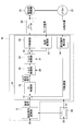
- FIG. 2 is a block diagram showing a configuration example of the drive system of the hybrid excavator shown in FIG.
- the mechanical power system is indicated by a double line
- the high-pressure hydraulic line is indicated by a solid line (thick line)
- the pilot line is indicated by a broken line
- the electric drive / control system is indicated by a solid line (thin line).
- the engine 11 as a mechanical drive unit and the motor generator 12 as an assist drive unit are connected to two input shafts of a transmission 13, respectively.
- a main pump 14 and a pilot pump 15 are connected to the output shaft of the transmission 13 as hydraulic pumps.
- a control valve 17 is connected to the main pump 14 via a high pressure hydraulic line 16.
- the main pump 14 is a swash plate type variable displacement hydraulic pump, and can control the discharge flow rate by adjusting the stroke length of the piston by controlling the angle (tilt angle) of the swash plate.
- the control valve 17 is a control device that controls the hydraulic system in the hybrid excavator.
- the hydraulic motors 1A (for right) and 1B (for left), the boom cylinder 7, the arm cylinder 8, and the bucket cylinder 9 for the lower traveling body 1 are connected to a control valve 17 via a high-pressure hydraulic line.
- the hydraulic motors 1A (for right) and 1B (for left), the boom cylinder 7, the arm cylinder 8, and the bucket cylinder 9 are collectively referred to as “hydraulic actuators”.
- the motor generator 12 is connected to a power storage system 120 including a battery via an inverter 18.
- the motor generator 12 and the inverter 18 constitute a motor generator system.
- An operation device 26 is connected to the pilot pump 15 through a pilot line 25.
- the operation device 26 includes a turning operation lever 26A, a hydraulic actuator operation lever 26B, and a hydraulic actuator operation pedal 26C.
- the turning operation lever 26A, the hydraulic actuator operation lever 26B, and the hydraulic actuator operation pedal 26C are connected to the control valve 17 and the pressure sensor 29 via hydraulic lines 27 and 28, respectively.
- the pressure sensor 29 is connected to a controller 30 that performs drive control of the electric system.
- the hybrid excavator shown in FIG. 2 is one in which the turning mechanism is electrically driven, and a turning electric motor 21 is provided to drive the turning mechanism 2.
- a turning electric motor 21 as an electric work element is connected to a power storage system 120 via an inverter 20.
- a resolver 22, a mechanical brake 23, and a turning transmission 24 are connected to the rotating shaft 21 ⁇ / b> A of the turning electric motor 21.
- the inverter 20, the turning electric motor 21, the resolver 22, the mechanical brake 23, and the turning transmission 24 constitute a load drive system.
- the controller 30 includes an arithmetic processing unit including a CPU (Central Processing Unit), an internal memory, and the like, and controls the operation of the motor generator 12 (switching between electric (assist) operation or power generation operation) and the electric motor 21 for turning. Perform operation control (switching between power running or regenerative operation). In addition, the controller 30 performs charge / discharge control of a capacitor (capacitor) by drivingly controlling a buck-boost converter as a buck-boost control unit.
- a CPU Central Processing Unit
- an internal memory and the like
- the controller 30 controls the operation of the motor generator 12 (switching between electric (assist) operation or power generation operation) and the electric motor 21 for turning. Perform operation control (switching between power running or regenerative operation).
- the controller 30 performs charge / discharge control of a capacitor (capacitor) by drivingly controlling a buck-boost converter as a buck-boost control unit.
- the controller 30 includes a state of charge of the capacitor (capacitor), an operation state of the motor generator 12 (electric (assist) operation or power generation operation), and an operation state of the turning motor 21 (power running operation or regenerative operation). ), The switching control between the step-up / step-down operation of the step-up / step-down converter is performed, and thereby the charge / discharge control of the capacitor (capacitor) is performed.
- the switching control between the step-up / step-down operation of the step-up / step-down converter includes the DC bus voltage value detected by the DC bus voltage detection unit provided in the DC bus, the capacitor voltage value detected by the capacitor voltage detection unit, and the capacitor This is performed based on the capacitor current value detected by the current detector.
- the SOC State Of Charge
- a capacitor is shown as an example of a capacitor.
- a secondary battery that can be charged and discharged such as a lithium ion battery, or another type of power source that can exchange power is used as a capacitor. Also good.
- FIG. 3 is a block diagram showing the configuration of the power storage system 120.
- the power storage system 120 includes a capacitor 19 as a battery, a buck-boost converter 100, and a DC bus 110.
- the DC bus 110 controls transmission and reception of electric power among the capacitor 19, the motor generator 12, and the turning electric motor 21.
- the capacitor 19 is provided with a capacitor voltage detector 112 for detecting the capacitor voltage value and a capacitor current detector 113 for detecting the capacitor current value.
- the capacitor voltage value detected by the capacitor voltage detection unit 112 and the capacitor current value detected by the capacitor current detection unit 113 are supplied to the controller 30.
- the buck-boost converter 100 performs control to switch between the step-up operation and the step-down operation so that the DC bus voltage value falls within a certain range according to the operating state of the motor generator 12 and the turning electric motor 21.
- the DC bus 110 is disposed between the inverters 18, 20 and the step-up / down converter 100, and transfers power between the capacitor 19, the motor generator 12, and the turning electric motor 21.
- the electric power generated by the motor generator 12 that is an assist motor and the regenerative power generated by the regenerative operation of the turning motor 21 are supplied to the DC bus of the power storage system 120 via the inverters 18 and 20. 110 and supplied to the capacitor 19 via the buck-boost converter 100.
- the controller 30 includes a drive control unit 32, a turning drive control unit 40, and a main control unit 60.
- Each of the drive control unit 32, the turning drive control unit 40, and the main control unit 60 is a functional element realized, for example, when the CPU of the controller 30 executes a drive control program stored in an internal memory. .
- the drive control unit 32 performs operation control of the motor generator 12 (switching between electric (assist) operation or power generation operation).
- the drive control unit 32 performs charge / discharge control of the capacitor 19 by driving and controlling the step-up / down converter 100 as the step-up / down control unit.
- the turning drive control unit 40 performs drive control of the turning electric motor 21 via the inverter 20.
- FIG. 4 is a control block diagram showing the configuration of the turning drive control unit 40.
- the turning drive control unit 40 generates a drive command for generating a speed command conversion unit 31 and a drive command for driving the turning electric motor 21. Part 50.
- the speed command conversion unit 31 is an arithmetic processing unit that converts a signal input from the pressure sensor 29 into a speed command. Thereby, the operation amount of the turning operation lever 26A is converted into a speed command (rad / s) for rotating the turning electric motor 21. This speed command is input to the drive control unit 32 and the drive command generation unit 50.
- the drive command generator 50 receives a speed command output from the speed command converter 31 according to the amount of operation of the turning lever 26A. Moreover, the drive command generation unit 50 generates a drive command based on the speed command. The drive command output from the drive command generation unit 50 is input to the inverter 20, and the inverter 20 AC drives the turning electric motor 21 with a PWM control signal based on the drive command.
- the turning drive control unit 40 controls the switching between the power running operation and the regenerative operation when the turning electric motor 21 is driven and controlled according to the operation amount of the turning operation lever 26 ⁇ / b> A, and the capacitor 19 through the inverter 20. Charge / discharge control.
- the drive command generation unit 50 includes a subtractor 51, a PI (Proportional Integral) control unit 52, a torque limiting unit 53, a torque limiting unit 54, a subtractor 55, a PI control unit 56, a current conversion unit 57, and a turning motion detection unit 58. including.
- PI Proportional Integral
- the subtractor 51 receives a speed command (rad / s) for turning driving corresponding to the operation amount of the turning motion lever 26A from the speed command converting unit 31, and receives the value of the speed command (hereinafter referred to as “speed command value”). ) Is subtracted from the rotational speed (rad / s) of the electric motor 21 for turning detected by the turning motion detector 58, and a deviation is output. This deviation is used in PI control for causing the rotational speed of the turning electric motor 21 to approach the speed command value (target value) in the PI control unit 52 described later.
- the PI control unit 52 Based on the deviation input from the subtractor 51, the PI control unit 52 performs PI control so that the rotation speed of the turning electric motor 21 approaches the speed command value (target value) (that is, this deviation is reduced). And calculate and generate a torque current command necessary for that. The generated torque current command is input to the torque limiter 53.
- the torque limiter 53 performs a process of limiting the value of the torque current command (hereinafter referred to as “torque current command value”) according to the operation amount of the turning lever 26A.
- This restriction process is performed based on a restriction characteristic in which the allowable value (absolute value) of the torque current command value gradually increases as the operation amount of the turning lever 26A increases.
- Such limitation of the torque current command value is performed in order to suppress this because the controllability deteriorates when the torque current command value calculated by the PI control unit 52 increases rapidly.
- the torque current command value is limited with respect to the bi-directional rotation of the upper swing body 3 in the left direction and the right direction.
- the data representing the limiting characteristic is stored in the internal memory of the main control unit 60, read by the CPU of the main control unit 60, and input to the torque limiting unit 53.
- the torque limiting unit 54 receives the torque current input from the torque limiting unit 53 so that the torque (absolute value) generated by the torque current command input from the torque limiting unit 53 is less than or equal to the maximum allowable torque value of the turning electric motor 21. Limit the command value.
- the torque current command value is limited with respect to the bi-directional rotation of the upper swing body 3 in the left direction and the right direction, similarly to the torque limiting unit 53.
- the torque limiter 54 is configured so that the torque (absolute value) generated by the torque current command input from the torque limiter 53 is less than or equal to the maximum allowable torque value of the turning electric motor 21 in one control cycle. If the increase / decrease width of the torque current command value is equal to or greater than the predetermined width, the increase / decrease width is limited to the predetermined width to prevent the torque current command value from rapidly increasing / decreasing.
- the torque limiter 54 applies the low-pass filter to the increase / decrease width, that is, adopts the increase / decrease width less than the predetermined width as it is, and limits the increase / decrease width greater than the predetermined width to the predetermined width,
- the torque current command value is prevented from suddenly increasing or decreasing.
- the torque limiting unit 54 can delay the turning speed of the upper turning body 3 from reaching the speed command value (target value).
- the subtractor 55 outputs a deviation obtained by subtracting the output value of the current converter 57 from the torque current command value input from the torque limiter 54.
- This deviation is a torque current command that is input via the torque limiter 54 to the driving torque of the turning electric motor 21 output from the current converter 57 in a feedback loop including a PI controller 56 and a current converter 57 described later. It is used for PI control to approach the torque represented by the value (target value).
- the PI control unit 56 performs PI control so as to reduce the deviation output from the subtractor 55, and generates a torque current command that is a final drive command to be sent to the inverter 20.
- the inverter 20 PWM drives the turning electric motor 21 based on the torque current command input from the PI control unit 56.
- the current converter 57 detects the motor current of the turning electric motor 21, converts it to a value corresponding to the torque current command, and outputs it to the subtractor 55.
- the turning motion detector 58 detects a change in the rotational position of the turning electric motor 21 detected by the resolver 22 (that is, the turning position of the upper turning body 3). Further, the turning motion detection unit 58 derives the rotational speed of the turning electric motor 21 by differential calculation from the temporal change of the rotational position. Data representing the derived rotational speed is input to the subtractor 51.
- a torque current command for driving the turning electric motor 21 is generated based on the speed command input from the speed command conversion unit 31.
- the upper swing body 3 is swung to a desired position.
- the main control unit 60 is a functional element that performs peripheral processing necessary for the control processing of the drive command generation unit 50, and includes an operation state detection unit 61.
- the operation state detection unit 61 is a functional element for detecting the operation state of the hybrid excavator. Based on the detection value of the pressure sensor 29, the operation state detection unit 61 detects operation states such as a single turning operation state, a combined turning operation state, and a stop state. To detect.
- the single turning operation state is a state in which the turning electric motor 21 is operated while the hydraulic actuator is stopped
- the compound turning operation state is a state in which both the turning electric motor 21 and the hydraulic actuator are operated
- the stopped state is a turning electric motor. 21 and the hydraulic actuator are both stopped.
- the pressure sensor 29 detects a pilot pressure corresponding to each operation amount of the turning operation lever 26A, the hydraulic actuator operation lever 26B, and the hydraulic actuator operation pedal 26C.
- the speed command conversion unit 31 controls the turning speed of the upper swing body 3 according to the operation state detected by the operation state detection unit 61.
- the speed command is converted into a speed limit for a single turning operation or a speed limit for a combined turning operation.
- the speed limit during the single turning operation is a speed limit adopted during the single turning operation
- the speed limit during the combined turning operation is a speed limit adopted during the combined turning operation.
- FIG. 5 is a diagram illustrating an example of speed command limiting characteristics by the speed command conversion unit 31, wherein the operation amount of the turning operation lever 26 ⁇ / b> A is arranged on the horizontal axis, and the speed command output from the speed command conversion unit 31 is plotted on the vertical axis. Arrange.
- the operation amount of the turning lever 26A is shown as a ratio when the maximum operation amount (operation amount at the time of full lever operation) is 100%.
- FIG. 5 shows the speed command limiting characteristic in the case of a right turn, but the same applies to the case of a left turn.
- the speed command output from the speed command conversion unit 31 to the drive command generation unit 50 is the same as that in the single turning operation and the combined turning when the operation amount of the turning operation lever 26 ⁇ / b> A is less than 60%. It follows the same transition as in operation, and increases as the amount of operation increases.
- the speed command at the time of a single turning operation increases with an increase in the operation amount when the operation amount is less than 80%, and the operation amount becomes 80% or more when the operation amount is less than 60%.
- the speed is limited by the speed limit SL for the single turning operation and becomes constant.
- the speed command at the time of the composite turning operation is limited by the speed limit PL at the time of the composite turning operation when the operation amount is 60% or more, and becomes constant at a timing earlier than that at the time of the single turning operation.
- the speed command conversion unit 31 reduces the turning speed of the upper swing body 3 during the combined turning operation when the operation amount of the turning operation lever 26A is equal to or greater than the predetermined amount compared to the single turning operation. Can do.
- the speed command conversion unit 31 changes the speed command restriction characteristic from that in the combined turning operation to that in the single turning operation. Try to switch to something.
- the speed command conversion unit 31 performs the combined turning when the operation amount of the turning operation lever 26A is maintained or reduced.
- the speed command limiting characteristic during operation may be used as it is. This is to prevent the turning speed from increasing immediately after the transition from the combined turning operation state to the single turning operation state, even though the operation amount of the turning operation lever 26A is maintained or reduced.
- the speed command converting unit 31 changes the speed command limiting characteristic to the composite turning when the operation amount of the turning operation lever 26A increases thereafter. You may make it switch from the thing at the time of operation
- the operation state detection unit 61 outputs a control signal to the torque limiting unit 54, and the maximum increase / decrease width (for deriving the torque current command value) used by the torque limiting unit 54 to limit the torque current command value.
- the maximum increase / decrease width in one control cycle) is switched.
- this switching process by the operation state detection unit 61 is referred to as “increase / decrease width restriction process”.
- the operation state detection unit 61 determines the maximum increase range of the torque current command value in one control cycle from the normal increase range. Reduce to an increase at the time of transition.
- the speed command limit characteristic is changed from the one during compound swing operation to the one during single swing operation during the transition from the combined swing operation state to the single swing operation state (when the speed command value increases) This is to prevent the turning speed from rapidly increasing even though the operation amount of the operation lever 26A is not changed.
- the increase width at the time of transition is the maximum increase width that is adopted when the operation state transitions from the combined swing operation state to the single swing operation state. This is the maximum increase that can be adopted.
- the operation state detection unit 61 sets the maximum increase width in one control cycle of the torque current command value to the normal increase width. Keep it. This is to prevent the increase in the turning speed corresponding to the increase in the operation amount of the turning operation lever 26A when the state is changed from the stop state to the single turning operation state or the combined turning operation state.
- the operation state detection unit 61 After switching from the normal increase range to the transition increase range, the operation state detection unit 61 performs a single control of the torque current command value when detecting the transition from the single turning operation state to the stop state.
- the maximum increase width in the cycle is returned from the increase width at the transition time to the normal time increase width.
- the operation state detection unit 61 changes the maximum increase width in one control cycle of the torque current command value from the increase width at the transition time to the normal time when the operation amount of the swing operation lever 26A decreases in the single swing operation state. You may make it return to an increase range. This is because when the operation of the turning operation lever 26A for increasing the turning speed is performed thereafter, the turning speed can be quickly increased.
- the maximum decrease width in one control cycle of the torque current command value is decreased from the normal time decrease width at the time of transition.
- the width may be reduced.
- the operation state detection unit 61 can prevent the turning speed from rapidly increasing or decreasing when switching between the combined turning operation state and the single turning operation state.
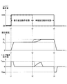
- various physical quantities (the operation amounts of the turning operation lever 26A and the hydraulic actuator (boom) operation lever 26B) when the operation state of the hybrid excavator shifts from the combined turning operation state to the single turning operation state.
- the time transition of the turning speed (refer to the middle part of FIG. 6) and the torque current command value (refer to the lower part of FIG. 6) will be described.
- the transition represented by the solid line in the upper part of FIG. 6 represents the transition of the operation amount of the turning lever 26A
- the transition represented by the one-dot chain line in the upper part of FIG. 6 represents the transition of the operation amount of the boom operation lever 26B. .
- transitions represented by solid lines in each of the middle stage of FIG. 6 and the lower stage of FIG. 6 explain the effect when the increase / decrease width limiting process by the operation state detection unit 61 is executed.
- transition represented by the broken line in each of the middle stage of FIG. 6 and the lower stage of FIG. 6 explains the effect when the increase / decrease width limiting process by the operation state detection unit 61 is not executed.
- the speed command output from the speed command conversion unit 31 is the speed limit during the combined turning operation.
- the torque current command value generated by the drive command generation unit 50 increases rapidly to reach the maximum allowable torque value T MAX .
- T MAX the maximum allowable torque value
- the turning speed of the upper-part turning body 3 rapidly increases to the combined turning operation limit speed PL, and after reaching the combined turning operation limit speed PL, the turning speed at the composite turning operation limit speed PL changes as it is.
- the torque current command value becomes close to zero when the turning speed of the upper turning body 3 reaches the combined turning operation limit speed PL.
- the operation amount of the turning operation lever 26A remains 100%. Even if it exists, the speed command is switched from the speed limit PL for the combined turning operation to the speed limit SL for the single turning operation. Then, since the maximum increase width of the torque current command value is reduced to the increase width at the time of transition by the torque limiter 54, the torque current command value becomes gentler than the sudden increase when the combined turning operation is started. To increase.
- the controller 30 sets the output of the turning electric motor 21 after the transition from the combined turning operation state to the single turning operation state to an output smaller than the output of the turning electric motor 21 in the single turning operation state other than after the transition.
- the turning speed of the upper-part turning body 3 gradually increases up to the limit speed SL for the single turning operation, compared with the rapid increase when the combined turning operation is started, and reaches the speed limit SL for the single turning operation. After that, the speed changes at the limit speed SL during the single turning operation.
- the torque current command value starts to decrease without reaching the maximum allowable torque value T MAX and becomes close to zero when the turning speed of the upper turning body 3 reaches the limit speed SL during the single turning operation.
- the speed command is switched from the single turning operation limit speed SL to zero.
- the torque current command value decreases rapidly and reaches the minimum allowable torque value T MIN (negative value).
- T MIN negative value
- the turning speed of the upper-part turning body 3 rapidly decreases to zero speed, and after reaching zero, it remains unchanged at zero speed.
- the torque current command value becomes zero when the turning speed of the upper turning body 3 reaches zero speed.
- the torque current command value is Similarly to the rapid increase when the combined turning operation is started, it rapidly increases and reaches the maximum allowable torque value T MAX (see the broken line in the lower part of FIG. 6). As a result, the turning speed of the upper-part turning body 3 also increases rapidly and reaches the speed limit SL for the single turning operation (see the broken line in the middle part of FIG. 6) in the same manner as the rapid increase when the combined turning operation is started. .
- the hybrid excavator according to the first embodiment when the operation state shifts from the combined turning operation state to the single turning operation state, the operation amount of the turning operation lever 26A is not changed. However, the turning speed is increased by increasing the speed command corresponding to the operation amount.
- the hybrid excavator according to the first embodiment is configured so that the discharge oil of the hydraulic pump is concentratedly supplied to the turning hydraulic actuator when the operation state shifts from the combined turning operation state to the single turning operation state, and the turning speed is increased. The operability of the hydraulic excavator that increases can be realized in a pseudo manner.
- the operator who is familiar with the hydraulic excavator has a sense of incongruity when using the hybrid excavator (discomfort that the turning speed does not increase even when the operating state shifts from the combined turning state to the single turning state) can do.
- the hybrid excavator according to the first embodiment gradually increases the turning speed when shifting from the combined turning operation state to the single turning operation state.
- the hybrid excavator according to the first embodiment can eliminate the uncomfortable feeling that the operator has when the turning speed rapidly increases when shifting from the combined turning operation state to the single turning operation state.
- the hybrid excavator according to the second embodiment is different from the hybrid excavator according to the first embodiment in that the switching of the speed command speed limit is prohibited in the transition from the combined turning operation state to the single turning operation state. However, it is common in other points.
- the speed command conversion unit 31 maintains the operation amount of the turning operation lever 26A even when the operation state detection unit 61 detects the transition from the combined turning operation state to the single turning operation state. If it is reduced or reduced, the speed command limiting characteristic during the combined turning operation is used as it is.
- this processing by the speed command conversion unit 31 is referred to as “limit characteristic maintaining processing”.
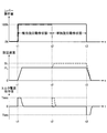
- FIG. 7 is a diagram corresponding to FIG. 6, and various physical quantities (the turning operation lever 26 ⁇ / b> A and the boom operation) when the operation state of the hybrid excavator according to the second embodiment shifts from the combined turning operation state to the single turning operation state.
- FIG. 7 shows temporal changes in the operation amount of the lever 26B (see the upper part of FIG. 7), the turning speed (see the middle part of FIG. 7), and the torque current command value (see the lower part of FIG. 7).
- 7 represents the transition of the operation amount of the turning lever 26A
- the transition represented by the alternate long and short dash line of FIG. 7 represents the transition of the operation amount of the boom operation lever 26B.
- the speed command output from the speed command conversion unit 31 is the speed limit during the combined turning operation.
- the torque current command value generated by the drive command generation unit 50 increases rapidly to reach the maximum allowable torque value T MAX .
- T MAX the maximum allowable torque value
- the turning speed of the upper-part turning body 3 rapidly increases up to the combined turning operation limit speed PL, and after reaching the combined turning operation limit speed PL, the turning speed remains unchanged at the combined turning operation limit speed PL.
- the torque current command value becomes close to zero when the turning speed of the upper turning body 3 reaches the combined turning operation limit speed PL.
- the controller 30 sets the output of the turning electric motor 21 after the transition from the combined turning operation state to the single turning operation state to an output smaller than the output of the turning electric motor 21 in the single turning operation state other than after the transition. Restrict.
- the turning speed of the upper-part turning body 3 remains unchanged at the combined turning operation limit speed PL even after shifting to the single turning operation state.
- the torque limiting unit 54 may not be provided.
- the speed command is switched from the combined turning operation limit speed PL to zero.
- the torque current command value decreases rapidly and reaches the minimum allowable torque value T MIN (negative value).
- T MIN negative value
- the turning speed of the upper-part turning body 3 rapidly decreases to zero speed, and after reaching zero, it remains unchanged at zero speed.
- the torque current command value becomes zero when the turning speed of the upper turning body 3 reaches zero speed.
- the speed command is changed from the speed limit PL during the combined turning operation to the time of the single turning operation at time t2.
- the torque current command value increases rapidly to reach the maximum allowable torque value T MAX in the same manner as the rapid increase when the combined turning operation is started (see the broken line in the lower part of FIG. 7). ).
- the turning speed of the upper-part turning body 3 also increases abruptly and reaches the speed limit SL for the single turning operation (see the broken line in the middle of FIG. 7), in the same manner as the rapid increase when the combined turning operation is started. .
- the hybrid excavator according to the second embodiment maintains the operation amount of the turning lever 26A even when the operating state shifts from the combined turning operation state to the single turning operation state.
- the speed command limit characteristic at the time of the combined turning operation is used as it is so as not to increase the turning speed.
- the turning speed increases even though the operation amount of the turning lever 26A does not increase during the transition from the combined turning operation state to the single turning operation state. This can eliminate the uncomfortable feeling that the operator has.
- the operation amount of the turning operation lever 26A is thereafter When the number is increased, the switching is executed, which is different from the hybrid excavator according to the second embodiment and common in other points.
- the speed command conversion unit 31 maintains or reduces the operation amount of the turning operation lever 26A when the operation state detection unit 61 detects the transition from the combined turning operation state to the single turning operation state. In such a case, the speed command limiting characteristic during the combined turning operation is used as it is. Then, the speed command conversion unit 31 switches the speed command limiting characteristic during the combined turning operation to the speed command limiting characteristic during the single turning operation when the operation amount of the turning operation lever 26A is subsequently increased.
- this processing by the speed command conversion unit 31 is referred to as “limit characteristic switching delay processing”.
- FIG. 8 is a diagram corresponding to FIGS. 6 and 7, and various physical quantities (swing operation lever 26 ⁇ / b> A) when the operation state of the hybrid excavator according to the third embodiment shifts from the combined turning operation state to the single turning operation state.
- the operation amount of the boom control lever 26B (see the upper part of FIG. 8), the turning speed (see the middle part of FIG. 8), and the torque current command value (see the lower part of FIG. 8)) over time.
- the transition represented by the solid line in the upper part of FIG. 8 indicates the transition of the operation amount of the turning lever 26A
- the transition represented by the alternate long and short dash line in FIG. 8 indicates the transition of the operation amount of the boom operation lever 26B. .
- transitions represented by solid lines in each of the middle stage of FIG. 8 and the lower stage of FIG. 8 explain the effect when the limit characteristic switching delay process by the speed command conversion unit 31 is executed. Further, transitions represented by broken lines in each of the middle stage of FIG. 8 and the lower stage of FIG. 8 explain the effect when the speed characteristic conversion delay process by the speed command conversion unit 31 is not executed.
- the speed command conversion unit 31 outputs.
- the speed command to be set is set to the combined speed limit speed PL.
- the torque current command value generated by the drive command generation unit 50 increases rapidly to reach the maximum allowable torque value T MAX .
- the turning speed of the upper-part turning body 3 rapidly increases to the combined turning operation limit speed PL, and after reaching the combined turning operation limit speed PL, the turning speed at the composite turning operation limit speed PL changes as it is.
- the torque current command value becomes close to zero when the turning speed of the upper turning body 3 reaches the combined turning operation limit speed PL.
- the operation amount of the boom operation lever 26B becomes 0%, and the operation state of the excavator shifts from the combined turning operation state to the single turning operation state.
- the speed command changes as the combined turning operation limit speed PL.
- the torque current command value remains in the vicinity of zero.
- the controller 30 sets the output of the turning electric motor 21 after the transition from the combined turning operation state to the single turning operation state to an output smaller than the output of the turning electric motor 21 in the single turning operation state other than after the transition. Restrict.
- the turning speed of the upper-part turning body 3 remains unchanged at the combined turning operation limit speed PL even after shifting to the single turning operation state.
- the torque limiting unit 54 may not be provided.
- the speed command is switched from the combined turning action speed limit PL to the single turning action speed limit SL.
- the torque current command value increases to reach the maximum allowable torque value T MAX .
- the controller 30 releases the output restriction of the turning electric motor 21.
- the turning speed of the upper-part turning body 3 also increases abruptly and reaches the speed limit SL for the single turning operation, similarly to the rapid increase when the combined turning operation is started.
- the speed command is switched from the single turning operation limit speed SL to zero.
- the torque current command value decreases rapidly and reaches the minimum allowable torque value T MIN (negative value).
- T MIN negative value
- the turning speed of the upper-part turning body 3 rapidly decreases to zero speed, and after reaching zero, it remains unchanged at zero speed.
- the torque current command value becomes zero when the turning speed of the upper turning body 3 reaches zero speed.
- the hybrid excavator according to the third embodiment maintains the operation amount of the turning lever 26A even when the operating state shifts from the combined turning operation state to the single turning operation state.
- the speed command limit characteristic at the time of the combined turning operation is used as it is so as not to increase the turning speed.
- the hybrid excavator according to the third embodiment increases the turning speed even when the operation amount of the turning operation lever 26A is not increased during the transition from the combined turning operation state to the single turning operation state. By doing so, it is possible to eliminate the uncomfortable feeling that the operator has.
- the hybrid excavator according to the third embodiment has the turning operation lever 26A even when the speed command limiting characteristic at the time of the composite turning operation is used as it is after the transition from the composite turning operation state to the single turning operation state.
- the speed command limiting characteristic during the combined turning operation is switched to the speed command limiting characteristic during the single turning operation.
- the hybrid excavator according to the third embodiment prevents the turning speed from unexpectedly increasing during the transition from the combined turning operation state to the single turning operation state, but thereafter the turning operation lever 26A
- the turning speed that exceeds the speed limit PL at the time of the combined turning operation and increases to the speed limit SL at the time of the single turning operation can realize a turning speed that suits the operator's intention.
- the speed conversion command unit 31 limits the speed command at the time of the compound turning operation.
- the torque current command value may be limited.
- the controller 30 can limit the output (for example, drive torque) of the turning electric motor 21 when the composite turning operation state is switched to the single turning operation state.
- the above-mentioned embodiment is applied to the case where it is applied to a hybrid excavator provided with the bucket 6, it may be applied to a hybrid work machine provided with a lifting magnet, a breaker, a fork and the like.
Abstract
Description
Claims (10)
- 上部旋回体を旋回させる旋回用電動機と、油圧アクチュエータと、該旋回用電動機による単独旋回動作状態、並びに、該旋回用電動機及び該油圧アクチュエータによる複合旋回動作状態での旋回制御を行うコントローラとを有するハイブリッド型作業機械であって、
前記コントローラは、複合旋回動作状態から単独旋回動作状態への移行後における単独旋回動作状態での前記旋回用電動機の出力を、該移行後以外の単独旋回動作状態での前記旋回用電動機の出力よりも小さい出力に制限する、
ことを特徴とするハイブリッド型作業機械。 - 前記コントローラは、複合旋回動作状態から移行した後の単独旋回動作状態において、前記旋回用電動機が発生させるトルクを制限することによって、旋回速度の増加を緩やかにする、
ことを特徴とする請求項1に記載のハイブリッド型作業機械。 - 旋回動作レバーの操作量に応じた速度指令を生成する速度指令生成部と、
前記速度指令と現在の旋回速度とに基づいてトルク電流指令を生成するトルク電流指令生成部と、を有し、
前記コントローラは、複合旋回動作状態から移行した後の単独旋回動作状態において、前記トルク電流指令の増加幅にフィルタをかけることによって、旋回速度の増加を緩やかにする、
ことを特徴とする請求項1に記載のハイブリッド型作業機械。 - 前記コントローラは、複合旋回動作状態から単独旋回動作状態への移行時において旋回動作レバーの操作量が不変の場合、複合旋回動作状態から単独旋回動作状態への移行後における単独旋回動作状態での前記旋回用電動機の出力を、前記移行後以外の単独旋回動作状態での前記旋回用電動機の出力よりも小さい出力に制限する、
ことを特徴とする請求項1に記載のハイブリッド型作業機械。 - 前記コントローラは、複合旋回動作状態から単独旋回動作状態への移行後において旋回動作レバーの操作量が変更されると、前記旋回用電動機の出力制限を解除する、
ことを特徴とする請求項4に記載のハイブリッド型作業機械。 - 上部旋回体を旋回させる旋回用電動機と、油圧アクチュエータと、該旋回用電動機による単独旋回動作状態、並びに、該旋回用電動機及び該油圧アクチュエータによる複合旋回動作状態での旋回制御を行うコントローラとを有するハイブリッド型作業機械の制御方法であって、
前記コントローラは、複合旋回動作状態から単独旋回動作状態への移行後における単独旋回動作状態での前記旋回用電動機の出力を、該移行後以外の単独旋回動作状態での前記旋回用電動機の出力よりも小さい出力に制限する、
ことを特徴とするハイブリッド型作業機械の制御方法。 - 前記コントローラは、複合旋回動作状態から移行した後の単独旋回動作状態において、前記旋回用電動機が発生させるトルクを制限することによって、旋回速度の増加を緩やかにする、
請求項6に記載のハイブリッド型作業機械の制御方法。 - 前記コントローラは、旋回動作レバーの操作量に応じた速度指令を生成し、前記速度指令と現在の旋回速度とに基づいてトルク電流指令を生成し、複合旋回動作状態から移行した後の単独旋回動作状態において、前記トルク電流指令の増加幅にフィルタをかけることによって、旋回速度の増加を緩やかにする、
請求項6に記載のハイブリッド型作業機械の制御方法。 - 前記コントローラは、複合旋回動作状態から単独旋回動作状態への移行時において旋回動作レバーの操作量が不変の場合、複合旋回動作状態から単独旋回動作状態への移行後における単独旋回動作状態での前記旋回用電動機の出力を、前記移行後以外の単独旋回動作状態での前記旋回用電動機の出力よりも小さい出力に制限する、
請求項6に記載のハイブリッド型作業機械の制御方法。 - 前記コントローラは、複合旋回動作状態から単独旋回動作状態への移行後において旋回動作レバーの操作量が変更されると、前記旋回用電動機の出力制限を解除する、
請求項9に記載のハイブリッド型作業機械の制御方法。
Priority Applications (5)
| Application Number | Priority Date | Filing Date | Title |
|---|---|---|---|
| JP2013522823A JP5913311B2 (ja) | 2011-06-27 | 2012-06-22 | ハイブリッド式作業機械及びその制御方法 |
| EP12803957.5A EP2725151B1 (en) | 2011-06-27 | 2012-06-22 | Hybrid work machine and method for controlling same |
| KR1020137030506A KR101549117B1 (ko) | 2011-06-27 | 2012-06-22 | 하이브리드식 작업기계 및 그 제어방법 |
| CN201280024124.2A CN103547743B (zh) | 2011-06-27 | 2012-06-22 | 混合式工作机械及其控制方法 |
| US14/101,487 US9382691B2 (en) | 2011-06-27 | 2013-12-10 | Hybrid work machine and method of controlling same |
Applications Claiming Priority (2)
| Application Number | Priority Date | Filing Date | Title |
|---|---|---|---|
| JP2011142340 | 2011-06-27 | ||
| JP2011-142340 | 2011-06-27 |
Related Child Applications (1)
| Application Number | Title | Priority Date | Filing Date |
|---|---|---|---|
| US14/101,487 Continuation US9382691B2 (en) | 2011-06-27 | 2013-12-10 | Hybrid work machine and method of controlling same |
Publications (1)
| Publication Number | Publication Date |
|---|---|
| WO2013002152A1 true WO2013002152A1 (ja) | 2013-01-03 |
Family
ID=47424047
Family Applications (1)
| Application Number | Title | Priority Date | Filing Date |
|---|---|---|---|
| PCT/JP2012/066065 WO2013002152A1 (ja) | 2011-06-27 | 2012-06-22 | ハイブリッド式作業機械及びその制御方法 |
Country Status (6)
| Country | Link |
|---|---|
| US (1) | US9382691B2 (ja) |
| EP (1) | EP2725151B1 (ja) |
| JP (1) | JP5913311B2 (ja) |
| KR (1) | KR101549117B1 (ja) |
| CN (1) | CN103547743B (ja) |
| WO (1) | WO2013002152A1 (ja) |
Cited By (3)
| Publication number | Priority date | Publication date | Assignee | Title |
|---|---|---|---|---|
| JP2014194120A (ja) * | 2013-03-28 | 2014-10-09 | Sumitomo Heavy Ind Ltd | 電動旋回制御装置 |
| JP2016113791A (ja) * | 2014-12-12 | 2016-06-23 | 住友重機械工業株式会社 | ショベル |
| EP3109366A4 (en) * | 2014-02-20 | 2017-11-01 | Hitachi Construction Machinery Co., Ltd. | Construction machine |
Families Citing this family (3)
| Publication number | Priority date | Publication date | Assignee | Title |
|---|---|---|---|---|
| US9402344B1 (en) * | 2015-01-20 | 2016-08-02 | Deere & Company | Power management for sugarcane harvesters |
| KR102391357B1 (ko) * | 2018-09-05 | 2022-04-27 | 가부시키가이샤 히다치 겡키 티에라 | 전동식 유압 작업 기계의 유압 구동 장치 |
| EP3943674A4 (en) * | 2019-03-19 | 2022-07-13 | Sumitomo Construction Machinery Co., Ltd. | EXCAVATOR |
Citations (5)
| Publication number | Priority date | Publication date | Assignee | Title |
|---|---|---|---|---|
| WO2007052538A1 (ja) | 2005-10-31 | 2007-05-10 | Komatsu Ltd. | 作業機械の制御装置 |
| JP2008088659A (ja) * | 2006-09-29 | 2008-04-17 | Kobelco Contstruction Machinery Ltd | 作業機械の旋回制御装置 |
| JP2009068245A (ja) * | 2007-09-13 | 2009-04-02 | Meidensha Corp | 建設機械のアーム駆動用制御装置 |
| JP2010106512A (ja) * | 2008-10-29 | 2010-05-13 | Kobelco Contstruction Machinery Ltd | 作業機械の旋回制御装置 |
| JP2011094451A (ja) * | 2009-11-02 | 2011-05-12 | Sumitomo (Shi) Construction Machinery Co Ltd | 建設機械の旋回制御装置 |
Family Cites Families (22)
| Publication number | Priority date | Publication date | Assignee | Title |
|---|---|---|---|---|
| JP3985756B2 (ja) * | 2003-09-05 | 2007-10-03 | コベルコ建機株式会社 | 建設機械の油圧制御回路 |
| KR101117533B1 (ko) * | 2004-07-05 | 2012-03-08 | 가부시키가이샤 고마쓰 세이사쿠쇼 | 선회 제어장치, 선회 제어방법, 및 건설기계 |
| JP4125337B2 (ja) * | 2006-10-02 | 2008-07-30 | 昭和シェル石油株式会社 | 太陽電池モジュール取付構造 |
| GB2457401B (en) * | 2007-01-18 | 2011-05-11 | Komatsu Mfg Co Ltd | Engine control device and its control method |
| KR101464016B1 (ko) * | 2007-03-29 | 2014-11-20 | 가부시키가이샤 고마쓰 세이사쿠쇼 | 작업 기계 |
| JP4827789B2 (ja) * | 2007-04-18 | 2011-11-30 | カヤバ工業株式会社 | 油圧アクチュエータ速度制御装置 |
| JP5064160B2 (ja) * | 2007-09-19 | 2012-10-31 | 株式会社小松製作所 | エンジンの制御装置 |
| JP5078693B2 (ja) * | 2008-03-26 | 2012-11-21 | カヤバ工業株式会社 | ハイブリッド建設機械の制御装置 |
| JP5074432B2 (ja) * | 2009-02-16 | 2012-11-14 | 住友重機械工業株式会社 | ハイブリッド型建設機械 |
| JP5220679B2 (ja) * | 2009-04-20 | 2013-06-26 | 住友重機械工業株式会社 | ハイブリッド型作業機械及びハイブリッド型作業機械の制御方法 |
| CN101920653B (zh) * | 2009-06-17 | 2015-02-18 | 上海捷能汽车技术有限公司 | 一种混合动力驱动系统的动力传输单元及传输控制方法 |
| EP2447119A4 (en) * | 2009-06-25 | 2018-04-04 | Sumitomo Heavy Industries, LTD. | Hybrid working machine and method of controlling working machine |
| CN102713085B (zh) * | 2010-01-29 | 2015-09-30 | 住友重机械工业株式会社 | 混合式施工机械 |
| JP5342473B2 (ja) * | 2010-02-25 | 2013-11-13 | ナブテスコ株式会社 | ハイブリッド建機の制御装置 |
| JP5703587B2 (ja) * | 2010-04-14 | 2015-04-22 | コベルコ建機株式会社 | ハイブリッド作業機械 |
| US8612102B2 (en) * | 2010-05-17 | 2013-12-17 | Komatsu Ltd. | Hydraulic excavator and hydraulic excavator control method |
| JP5203434B2 (ja) * | 2010-09-08 | 2013-06-05 | 日立建機株式会社 | ハイブリッド建設機械 |
| JP5738674B2 (ja) * | 2011-05-25 | 2015-06-24 | コベルコ建機株式会社 | 旋回式作業機械 |
| US8850806B2 (en) * | 2011-06-28 | 2014-10-07 | Caterpillar Inc. | Hydraulic control system having swing motor energy recovery |
| US8909434B2 (en) * | 2011-06-29 | 2014-12-09 | Caterpillar, Inc. | System and method for controlling power in machine having electric and/or hydraulic devices |
| JP5954054B2 (ja) * | 2012-08-30 | 2016-07-20 | コベルコ建機株式会社 | ハイブリッド式建設機械の蓄電装置暖機装置 |
| JP5192605B1 (ja) * | 2012-09-28 | 2013-05-08 | 株式会社小松製作所 | ホイールローダ |
-
2012
- 2012-06-22 CN CN201280024124.2A patent/CN103547743B/zh active Active
- 2012-06-22 JP JP2013522823A patent/JP5913311B2/ja not_active Expired - Fee Related
- 2012-06-22 EP EP12803957.5A patent/EP2725151B1/en active Active
- 2012-06-22 KR KR1020137030506A patent/KR101549117B1/ko active IP Right Grant
- 2012-06-22 WO PCT/JP2012/066065 patent/WO2013002152A1/ja active Application Filing
-
2013
- 2013-12-10 US US14/101,487 patent/US9382691B2/en active Active
Patent Citations (5)
| Publication number | Priority date | Publication date | Assignee | Title |
|---|---|---|---|---|
| WO2007052538A1 (ja) | 2005-10-31 | 2007-05-10 | Komatsu Ltd. | 作業機械の制御装置 |
| JP2008088659A (ja) * | 2006-09-29 | 2008-04-17 | Kobelco Contstruction Machinery Ltd | 作業機械の旋回制御装置 |
| JP2009068245A (ja) * | 2007-09-13 | 2009-04-02 | Meidensha Corp | 建設機械のアーム駆動用制御装置 |
| JP2010106512A (ja) * | 2008-10-29 | 2010-05-13 | Kobelco Contstruction Machinery Ltd | 作業機械の旋回制御装置 |
| JP2011094451A (ja) * | 2009-11-02 | 2011-05-12 | Sumitomo (Shi) Construction Machinery Co Ltd | 建設機械の旋回制御装置 |
Non-Patent Citations (1)
| Title |
|---|
| See also references of EP2725151A4 |
Cited By (3)
| Publication number | Priority date | Publication date | Assignee | Title |
|---|---|---|---|---|
| JP2014194120A (ja) * | 2013-03-28 | 2014-10-09 | Sumitomo Heavy Ind Ltd | 電動旋回制御装置 |
| EP3109366A4 (en) * | 2014-02-20 | 2017-11-01 | Hitachi Construction Machinery Co., Ltd. | Construction machine |
| JP2016113791A (ja) * | 2014-12-12 | 2016-06-23 | 住友重機械工業株式会社 | ショベル |
Also Published As
| Publication number | Publication date |
|---|---|
| JPWO2013002152A1 (ja) | 2015-02-23 |
| KR101549117B1 (ko) | 2015-09-01 |
| EP2725151A1 (en) | 2014-04-30 |
| EP2725151B1 (en) | 2016-08-03 |
| CN103547743A (zh) | 2014-01-29 |
| US20140107898A1 (en) | 2014-04-17 |
| KR20140009507A (ko) | 2014-01-22 |
| JP5913311B2 (ja) | 2016-04-27 |
| EP2725151A4 (en) | 2015-05-13 |
| US9382691B2 (en) | 2016-07-05 |
| CN103547743B (zh) | 2015-12-02 |
Similar Documents
| Publication | Publication Date | Title |
|---|---|---|
| JP5149826B2 (ja) | ハイブリッド式作業機械及びサーボ制御システム | |
| JP5356427B2 (ja) | ハイブリッド式建設機械 | |
| KR101229330B1 (ko) | 선회구동제어장치 및 이를 포함하는 건설기계 | |
| JP5913311B2 (ja) | ハイブリッド式作業機械及びその制御方法 | |
| JP5519484B2 (ja) | ハイブリッド型建設機械 | |
| JP5095361B2 (ja) | 旋回駆動制御装置及びこれを含む建設機械 | |
| JP2010173599A (ja) | ハイブリッド式作業機械の制御方法、及びサーボ制御システムの制御方法 | |
| JP5074432B2 (ja) | ハイブリッド型建設機械 | |
| JP5917304B2 (ja) | ショベルの制御方法 | |
| JP5101406B2 (ja) | 建設機械 | |
| JP5611532B2 (ja) | サーボ制御システムおよび作業機械 | |
| JP2014001793A (ja) | 油圧ショベル | |
| JP5968819B2 (ja) | 電動旋回制御装置 | |
| JP5808635B2 (ja) | ハイブリッド式ショベルの制御方法 | |
| JP5864309B2 (ja) | ショベル | |
| JP5976471B2 (ja) | ショベルの制御方法 | |
| JP6628971B2 (ja) | ショベル | |
| JP5814835B2 (ja) | ショベル | |
| JP6347977B2 (ja) | ショベル | |
| JP5037558B2 (ja) | ハイブリッド型建設機械 | |
| JP5207232B2 (ja) | 旋回駆動制御装置及びこれを含む建設機械 | |
| JP2010150897A (ja) | 旋回駆動制御装置及びこれを含む建設機械 | |
| JP6042303B2 (ja) | 作業車両 | |
| JP2009293668A (ja) | 建設機械 | |
| JP2018141290A (ja) | ショベル |
Legal Events
| Date | Code | Title | Description |
|---|---|---|---|
| 121 | Ep: the epo has been informed by wipo that ep was designated in this application |
Ref document number: 12803957 Country of ref document: EP Kind code of ref document: A1 |
|
| DPE1 | Request for preliminary examination filed after expiration of 19th month from priority date (pct application filed from 20040101) | ||
| ENP | Entry into the national phase |
Ref document number: 20137030506 Country of ref document: KR Kind code of ref document: A |
|
| ENP | Entry into the national phase |
Ref document number: 2013522823 Country of ref document: JP Kind code of ref document: A |
|
| NENP | Non-entry into the national phase |
Ref country code: DE |
|
| REEP | Request for entry into the european phase |
Ref document number: 2012803957 Country of ref document: EP |
|
| WWE | Wipo information: entry into national phase |
Ref document number: 2012803957 Country of ref document: EP |