WO2013001985A1 - めっき処理装置、めっき処理方法および記憶媒体 - Google Patents
めっき処理装置、めっき処理方法および記憶媒体 Download PDFInfo
- Publication number
- WO2013001985A1 WO2013001985A1 PCT/JP2012/064380 JP2012064380W WO2013001985A1 WO 2013001985 A1 WO2013001985 A1 WO 2013001985A1 JP 2012064380 W JP2012064380 W JP 2012064380W WO 2013001985 A1 WO2013001985 A1 WO 2013001985A1
- Authority
- WO
- WIPO (PCT)
- Prior art keywords
- substrate
- plating solution
- plating
- nozzle
- temperature
- Prior art date
- Legal status (The legal status is an assumption and is not a legal conclusion. Google has not performed a legal analysis and makes no representation as to the accuracy of the status listed.)
- Ceased
Links
Images








Classifications
-
- C—CHEMISTRY; METALLURGY
- C23—COATING METALLIC MATERIAL; COATING MATERIAL WITH METALLIC MATERIAL; CHEMICAL SURFACE TREATMENT; DIFFUSION TREATMENT OF METALLIC MATERIAL; COATING BY VACUUM EVAPORATION, BY SPUTTERING, BY ION IMPLANTATION OR BY CHEMICAL VAPOUR DEPOSITION, IN GENERAL; INHIBITING CORROSION OF METALLIC MATERIAL OR INCRUSTATION IN GENERAL
- C23C—COATING METALLIC MATERIAL; COATING MATERIAL WITH METALLIC MATERIAL; SURFACE TREATMENT OF METALLIC MATERIAL BY DIFFUSION INTO THE SURFACE, BY CHEMICAL CONVERSION OR SUBSTITUTION; COATING BY VACUUM EVAPORATION, BY SPUTTERING, BY ION IMPLANTATION OR BY CHEMICAL VAPOUR DEPOSITION, IN GENERAL
- C23C18/00—Chemical coating by decomposition of either liquid compounds or solutions of the coating forming compounds, without leaving reaction products of surface material in the coating; Contact plating
- C23C18/16—Chemical coating by decomposition of either liquid compounds or solutions of the coating forming compounds, without leaving reaction products of surface material in the coating; Contact plating by reduction or substitution, e.g. electroless plating
- C23C18/31—Coating with metals
-
- B—PERFORMING OPERATIONS; TRANSPORTING
- B05—SPRAYING OR ATOMISING IN GENERAL; APPLYING FLUENT MATERIALS TO SURFACES, IN GENERAL
- B05C—APPARATUS FOR APPLYING FLUENT MATERIALS TO SURFACES, IN GENERAL
- B05C5/00—Apparatus in which liquid or other fluent material is projected, poured or allowed to flow on to the surface of the work
- B05C5/001—Apparatus in which liquid or other fluent material is projected, poured or allowed to flow on to the surface of the work incorporating means for heating or cooling the liquid or other fluent material
-
- C—CHEMISTRY; METALLURGY
- C23—COATING METALLIC MATERIAL; COATING MATERIAL WITH METALLIC MATERIAL; CHEMICAL SURFACE TREATMENT; DIFFUSION TREATMENT OF METALLIC MATERIAL; COATING BY VACUUM EVAPORATION, BY SPUTTERING, BY ION IMPLANTATION OR BY CHEMICAL VAPOUR DEPOSITION, IN GENERAL; INHIBITING CORROSION OF METALLIC MATERIAL OR INCRUSTATION IN GENERAL
- C23C—COATING METALLIC MATERIAL; COATING MATERIAL WITH METALLIC MATERIAL; SURFACE TREATMENT OF METALLIC MATERIAL BY DIFFUSION INTO THE SURFACE, BY CHEMICAL CONVERSION OR SUBSTITUTION; COATING BY VACUUM EVAPORATION, BY SPUTTERING, BY ION IMPLANTATION OR BY CHEMICAL VAPOUR DEPOSITION, IN GENERAL
- C23C18/00—Chemical coating by decomposition of either liquid compounds or solutions of the coating forming compounds, without leaving reaction products of surface material in the coating; Contact plating
- C23C18/16—Chemical coating by decomposition of either liquid compounds or solutions of the coating forming compounds, without leaving reaction products of surface material in the coating; Contact plating by reduction or substitution, e.g. electroless plating
- C23C18/1601—Process or apparatus
- C23C18/1619—Apparatus for electroless plating
-
- B—PERFORMING OPERATIONS; TRANSPORTING
- B05—SPRAYING OR ATOMISING IN GENERAL; APPLYING FLUENT MATERIALS TO SURFACES, IN GENERAL
- B05D—PROCESSES FOR APPLYING FLUENT MATERIALS TO SURFACES, IN GENERAL
- B05D1/00—Processes for applying liquids or other fluent materials
- B05D1/02—Processes for applying liquids or other fluent materials performed by spraying
-
- C—CHEMISTRY; METALLURGY
- C23—COATING METALLIC MATERIAL; COATING MATERIAL WITH METALLIC MATERIAL; CHEMICAL SURFACE TREATMENT; DIFFUSION TREATMENT OF METALLIC MATERIAL; COATING BY VACUUM EVAPORATION, BY SPUTTERING, BY ION IMPLANTATION OR BY CHEMICAL VAPOUR DEPOSITION, IN GENERAL; INHIBITING CORROSION OF METALLIC MATERIAL OR INCRUSTATION IN GENERAL
- C23C—COATING METALLIC MATERIAL; COATING MATERIAL WITH METALLIC MATERIAL; SURFACE TREATMENT OF METALLIC MATERIAL BY DIFFUSION INTO THE SURFACE, BY CHEMICAL CONVERSION OR SUBSTITUTION; COATING BY VACUUM EVAPORATION, BY SPUTTERING, BY ION IMPLANTATION OR BY CHEMICAL VAPOUR DEPOSITION, IN GENERAL
- C23C18/00—Chemical coating by decomposition of either liquid compounds or solutions of the coating forming compounds, without leaving reaction products of surface material in the coating; Contact plating
- C23C18/16—Chemical coating by decomposition of either liquid compounds or solutions of the coating forming compounds, without leaving reaction products of surface material in the coating; Contact plating by reduction or substitution, e.g. electroless plating
- C23C18/1601—Process or apparatus
- C23C18/1633—Process of electroless plating
- C23C18/1655—Process features
- C23C18/1664—Process features with additional means during the plating process
- C23C18/1669—Agitation, e.g. air introduction
-
- C—CHEMISTRY; METALLURGY
- C23—COATING METALLIC MATERIAL; COATING MATERIAL WITH METALLIC MATERIAL; CHEMICAL SURFACE TREATMENT; DIFFUSION TREATMENT OF METALLIC MATERIAL; COATING BY VACUUM EVAPORATION, BY SPUTTERING, BY ION IMPLANTATION OR BY CHEMICAL VAPOUR DEPOSITION, IN GENERAL; INHIBITING CORROSION OF METALLIC MATERIAL OR INCRUSTATION IN GENERAL
- C23C—COATING METALLIC MATERIAL; COATING MATERIAL WITH METALLIC MATERIAL; SURFACE TREATMENT OF METALLIC MATERIAL BY DIFFUSION INTO THE SURFACE, BY CHEMICAL CONVERSION OR SUBSTITUTION; COATING BY VACUUM EVAPORATION, BY SPUTTERING, BY ION IMPLANTATION OR BY CHEMICAL VAPOUR DEPOSITION, IN GENERAL
- C23C18/00—Chemical coating by decomposition of either liquid compounds or solutions of the coating forming compounds, without leaving reaction products of surface material in the coating; Contact plating
- C23C18/16—Chemical coating by decomposition of either liquid compounds or solutions of the coating forming compounds, without leaving reaction products of surface material in the coating; Contact plating by reduction or substitution, e.g. electroless plating
- C23C18/1601—Process or apparatus
- C23C18/1633—Process of electroless plating
- C23C18/1675—Process conditions
- C23C18/1676—Heating of the solution
-
- C—CHEMISTRY; METALLURGY
- C23—COATING METALLIC MATERIAL; COATING MATERIAL WITH METALLIC MATERIAL; CHEMICAL SURFACE TREATMENT; DIFFUSION TREATMENT OF METALLIC MATERIAL; COATING BY VACUUM EVAPORATION, BY SPUTTERING, BY ION IMPLANTATION OR BY CHEMICAL VAPOUR DEPOSITION, IN GENERAL; INHIBITING CORROSION OF METALLIC MATERIAL OR INCRUSTATION IN GENERAL
- C23C—COATING METALLIC MATERIAL; COATING MATERIAL WITH METALLIC MATERIAL; SURFACE TREATMENT OF METALLIC MATERIAL BY DIFFUSION INTO THE SURFACE, BY CHEMICAL CONVERSION OR SUBSTITUTION; COATING BY VACUUM EVAPORATION, BY SPUTTERING, BY ION IMPLANTATION OR BY CHEMICAL VAPOUR DEPOSITION, IN GENERAL
- C23C18/00—Chemical coating by decomposition of either liquid compounds or solutions of the coating forming compounds, without leaving reaction products of surface material in the coating; Contact plating
- C23C18/16—Chemical coating by decomposition of either liquid compounds or solutions of the coating forming compounds, without leaving reaction products of surface material in the coating; Contact plating by reduction or substitution, e.g. electroless plating
- C23C18/1601—Process or apparatus
- C23C18/1633—Process of electroless plating
- C23C18/1675—Process conditions
- C23C18/168—Control of temperature, e.g. temperature of bath, substrate
Definitions
- the present invention relates to a plating apparatus, a plating method, and a storage medium for supplying a plating solution to the surface of a substrate to perform a plating process.
- wirings are formed on a substrate such as a semiconductor wafer or a liquid crystal substrate in order to form a circuit on the surface.
- a copper material having low electrical resistance and high reliability has come to be used.
- copper is more easily oxidized than aluminum, it is desirable to perform plating with a metal having high electromigration resistance in order to prevent oxidation of the copper wiring surface.
- Patent Document 1 proposes a plating apparatus including a substrate rotation mechanism that rotates a substrate, a nozzle that discharges a plating solution onto the substrate, and a nozzle movement mechanism that moves the nozzle in a direction along the substrate. ing.
- a uniform flow of the plating solution is formed on the surface of the substrate by supplying the plating solution while rotating the substrate.
- the plating process is uniformly performed over the entire surface of the substrate.
- the plating process by electroless plating is affected by reaction conditions such as the composition of the plating solution and temperature.
- reaction conditions such as the composition of the plating solution and temperature.
- An object of the present invention is to provide a plating apparatus, a plating method, and a storage medium that can effectively solve such problems.
- a plating apparatus for performing a plating process by supplying a plating solution to a substrate, the substrate rotation holding mechanism for holding and rotating the substrate, and the substrate rotation holding mechanism.
- a discharge mechanism for discharging a plating solution toward the held substrate;
- a plating solution supply mechanism that supplies the plating solution to the discharge mechanism; and
- a control mechanism that controls the discharge mechanism and the plating solution supply mechanism. The discharge mechanism discharges the plating solution toward the substrate.
- a plating method for performing a plating process by supplying a plating solution to a substrate, wherein the substrate is disposed on a substrate rotation holding mechanism, and the substrate is disposed via a discharge mechanism.
- Discharging the plating solution, and the discharge mechanism includes a first nozzle including a discharge port for discharging the plating solution toward the substrate, and a central portion of the substrate rather than the discharge port of the first nozzle.
- a plating method characterized by being higher than the temperature of the plating solution discharged.
- the plating method performs plating by supplying a plating solution to the substrate.
- a method comprising: disposing the substrate on a substrate rotation holding mechanism; and discharging a plating solution to the substrate via a discharge mechanism, wherein the discharge mechanism discharges the plating solution toward the substrate.
- the temperature of the plating solution discharged from the nozzle toward the substrate is higher than the temperature of the plating solution discharged from the second nozzle toward the substrate.
- Medium is provided.
- the discharge mechanism that discharges the plating solution toward the substrate includes the first nozzle including the discharge port that discharges the plating solution toward the substrate, and the central portion of the substrate from the discharge port of the first nozzle. And a second nozzle including a discharge port that can be positioned close to each other.
- the plating solution supply mechanism that supplies the plating solution to the discharge mechanism is configured such that the temperature of the plating solution supplied to the first nozzle is higher than the temperature of the plating solution supplied to the second nozzle. For this reason, the plating solution supplied from the first nozzle and the plating solution supplied from the second nozzle are mixed at the peripheral portion of the substrate, whereby the temperature of the plating solution at the peripheral portion of the substrate is changed to the first nozzle.
- FIG. 1 is a plan view showing a schematic configuration of a plating system in an embodiment of the present invention.
- FIG. 2 is a side view showing the plating apparatus in the embodiment of the present invention.
- FIG. 3 is a plan view of the plating apparatus shown in FIG.
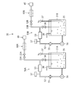
- FIG. 4 is a diagram showing a plating solution supply mechanism in the embodiment of the present invention.
- FIG. 5 is a view showing a first heating means of the plating solution supply mechanism.
- FIG. 6 is a view showing a second heating means of the plating solution supply mechanism.
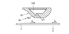
- 7 is a cross-sectional view of the second nozzle of FIG. 3 as viewed from the VII-VII direction.
- FIG. 8 is a flowchart showing a plating method.
- FIGS. 1 is a plan view showing a schematic configuration of a plating system in an embodiment of the present invention.
- FIG. 2 is a side view showing the plating apparatus in the embodiment of the present invention.
- FIG. 3 is a plan view of the
- FIG. 10 is a diagram illustrating a manner in which a plating solution is discharged from a nozzle having a vertical discharge port toward a substrate in a comparative embodiment.
- FIG. 11 is a view showing a modification of the plating solution supply mechanism.
- FIG. 12 is a plan view showing a modification of the second nozzle. 13 is a cross-sectional view of the second nozzle of FIG. 12 as viewed from the XIII-XIII direction.
- FIG. 14 is a plan view showing a modification of the first nozzle.
- FIGS. 15A and 15B are views showing a first modification of the second nozzle control method.
- FIGS. 16A and 16B are views showing a second modification of the second nozzle control method.
- FIG. 17 is a view showing a further modification of the first nozzle 40.
- FIG. 18 is a diagram showing a result of measuring the temperature of the substrate in the example.
- FIGS. 1 to 9A to 9E First, referring to FIG. 1, the entire plating system 1 in this embodiment will be described.
- the plating system 1 mounts a carrier 3 that accommodates a plurality of substrates 2 (here, 25 semiconductor wafers) (for example, 25 wafers), and carries in a predetermined number of substrates 2. And a substrate loading / unloading chamber 5 for unloading and a substrate processing chamber 6 for performing various processes such as plating and cleaning of the substrate 2.
- the substrate carry-in / out chamber 5 and the substrate processing chamber 6 are provided adjacent to each other.
- the substrate carry-in / out chamber 5 includes a carrier placement unit 4, a transfer chamber 9 that stores the transfer device 8, and a substrate transfer chamber 11 that stores a substrate transfer table 10.
- the transfer chamber 9 and the substrate delivery chamber 11 are connected to each other via a delivery port 12.
- the carrier placement unit 4 places a plurality of carriers 3 that accommodate a plurality of substrates 2 in a horizontal state.
- the substrate 2 is transferred, and in the substrate transfer chamber 11, the substrate 2 is transferred to and from the substrate processing chamber 6.
- a predetermined number of substrates 2 are transported by the transport device 8 between any one carrier 3 placed on the carrier platform 4 and the substrate delivery table 10.
- the substrate processing chamber 6 is arranged in the front and back on one side and the other side of the substrate transfer unit 13 and extends in the front and back in the central portion, and supplies the plating solution to the substrate 2 to perform the plating process.
- a plurality of plating processing apparatuses 20 are arranged in the front and back on one side and the other side of the substrate transfer unit 13 and extends in the front and back in the central portion, and supplies the plating solution to the substrate 2 to perform the plating process.
- a plurality of plating processing apparatuses 20 is arranged in the front and back on one side and the other side of the substrate transfer unit 13 and extends in the front and back in the central portion, and supplies the plating solution to the substrate 2 to perform the plating process.
- the substrate transport unit 13 includes a substrate transport device 14 configured to be movable in the front-rear direction.
- the substrate transfer unit 13 communicates with the substrate transfer table 10 in the substrate transfer chamber 11 via the substrate transfer port 15.
- the substrates 2 are transferred to the respective plating processing apparatuses 20 in a state where the substrates 2 are held horizontally one by one by the substrate transfer device 14 of the substrate transfer unit 13.
- the cleaning process and the plating process are performed on the substrate 2 one by one.
- Each plating apparatus 20 is different only in the plating solution used, and the other configurations are substantially the same. Therefore, in the following description, the configuration of one plating processing apparatus 20 among the plurality of plating processing apparatuses 20 will be described.
- FIG. 2 is a side view showing the plating apparatus 20
- FIG. 3 is a plan view showing the plating apparatus 20.
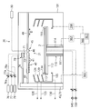
- the plating apparatus 20 holds the substrate 2 inside the casing 101 and rotates the substrate 2 on the surface of the substrate 2 held by the substrate rotation holding mechanism 110.
- a discharge mechanism 21 that discharges the plating liquid toward the discharge mechanism, a plating liquid supply mechanism 30 that supplies the plating liquid to the discharge mechanism 21, and a cup 105 that is driven up and down by an elevating mechanism 164 and has discharge ports 124, 129, and 134.
- the liquid discharge mechanisms 120, 125, and 130 for collecting and discharging the plating solution and the like scattered from the substrate 2 to the discharge ports 124, 129, and 134, the substrate rotation holding mechanism 110, the discharge mechanism 21, and the plating solution supply mechanism 30 are controlled. And a control mechanism 160.
- the substrate rotation holding mechanism 110 includes a hollow cylindrical rotation shaft 111 extending vertically in the casing 101, and a turntable 112 attached to the upper end portion of the rotation shaft 111. And a wafer chuck 113 that is provided on the outer peripheral portion of the upper surface of the turntable 112 and supports the substrate 2, and a rotation mechanism 162 that rotates the rotation shaft 111.
- the rotation mechanism 162 is controlled by the control mechanism 160, and the rotation shaft 111 is rotationally driven by the rotation mechanism 162, whereby the substrate 2 supported by the wafer chuck 113 is rotated.
- the discharge mechanism 21 includes a first nozzle 40 and a second nozzle 45 that discharge a chemical reduction type plating solution such as a CoP plating solution toward the substrate 2.
- the chemical reduction type plating solution is supplied from the plating solution supply mechanism 30 to the first nozzle 40 and the second nozzle 45. Details of the first nozzle 40 and the second nozzle 45 will be described later.
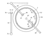
- the discharge mechanism 21 may further include a third nozzle 70 including a discharge port 71 and a discharge port 72 as shown in FIG. As shown in FIGS. 2 and 3, the third nozzle 70 is attached to the distal end portion of the arm 74, and the arm 74 can extend in the vertical direction and is rotated by the rotation mechanism 165. 73 is fixed.
- the discharge port 71 is connected through a valve 76a to a plating solution supply mechanism 76 that supplies a replacement type plating solution, for example, a Pd plating solution.
- the discharge port 72 is connected to a cleaning process liquid supply mechanism 77 that supplies a cleaning process liquid via a valve 77a.
- a rinsing treatment liquid supply for supplying a pretreatment liquid for pretreatment performed prior to the plating process, for example, a rinsing treatment liquid such as pure water, to the discharge port 72 of the third nozzle 70.
- a mechanism 78 may be further connected via a valve 78a. In this case, by appropriately controlling the opening and closing of the valve 77a and the valve 78a, either the cleaning processing liquid or the rinsing processing liquid is selectively discharged from the discharge port 72 onto the substrate 2.
- the first nozzle 40 includes a plurality of discharge ports 41.
- the first nozzle 40 is attached to the tip of the arm 44.
- the arm 44 can be extended in the vertical direction and is fixed to a support shaft 43 that is rotationally driven by a rotation mechanism 165.
- the discharge ports 41 of the first nozzle 40 are provided so as to be aligned along the radial direction of the substrate 2. Therefore, the plating solution can be directly supplied from the first nozzle 40 to a region within a predetermined range in the radial direction of the substrate 2 in the region on the substrate 2.
- directly supplying means that the path for the plating solution to reach a predetermined region on the substrate 2 is caused by the rotation of the substrate 2 when the plating solution dropped on the center side of the substrate 2 from the predetermined region. This means that it is not a path that reaches the predetermined area by the centrifugal force, but a path that the plating solution is dropped onto the predetermined area.
- the ambient temperature in the plating apparatus 20 or the temperature of the substrate 2 is lower than the temperature of the plating solution when discharged from the first nozzle 40 or the second nozzle 45 toward the substrate 2. For this reason, when the plating solution dropped on or near the center portion of the substrate 2 flows outwardly by centrifugal force on the substrate 2, the temperature of the plating solution is considered to become lower toward the peripheral side of the substrate 2. .
- the temperature of the plating solution on the substrate 2 is: It is thought that it becomes low as it goes from the center part of the board
- the plating solution is supplied to the first nozzle 40 in a region within a predetermined range in the radial direction of the substrate 2 in the region on the substrate 2. Can be supplied directly from. For this reason, there is a difference between the temperature of the plating solution that reaches the region on the peripheral side of the center portion of the substrate 2 in the region on the substrate 2 and the temperature of the plating solution that reaches the center portion of the substrate. Can be suppressed.
- the second nozzle 45 includes a discharge port 46.
- the second nozzle 45 is attached to the tip of an arm 49, and the arm 49 is configured to be able to advance and retract in the radial direction of the substrate 2 (the direction indicated by the arrow D in FIGS. 2 and 3). ing. Therefore, the second nozzle 45 has a central position where the discharge port 46 of the second nozzle 45 is closer to the center of the substrate 2 than each discharge port 41 of the first nozzle 40, and a peripheral edge that is closer to the peripheral side than the central position. It can move between positions.
- the second nozzle at the center position is indicated by reference numeral 45 ′
- the second nozzle at the peripheral position is indicated by reference numeral 45 ′′.
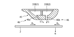
- FIG. 7 is a sectional view of the second nozzle 45 shown in FIG. 3 as viewed from the VII-VII direction.
- the arrow shown by reference numeral R 1 indicates the direction of rotation (first rotational direction) when the substrate 2 rotates clockwise
- the arrow indicated by reference numeral R 2 the substrate 2 is The rotation direction (second rotation direction) when rotating counterclockwise is shown.
- the discharge port 46 of the second nozzle 45 is represented by an inclination direction (indicated by an arrow S ⁇ b> 1 in FIG. 7) inclined from the normal direction of the substrate 2 (direction indicated by the arrow N in FIG. 7).
- Inclined discharge ports 46 a configured to discharge the plating solution 35 toward the substrate 2 in the direction of
- “inclined” means that the arrow N and the arrow S 1 are not parallel to each other and the arrow N and the arrow S 1 are not orthogonal to each other in FIG.
- the inclined discharge port 46a is inclined direction S 1 of the inclined discharge port 46a is configured to correspond to the first rotational direction R 1.
- the "inclination direction S 1 of the inclined discharge port 46a corresponds to the first rotational direction R 1" is a vector S 1 indicating a discharge direction of the plating liquid discharged from the inclined discharge port 46a, shown in FIG. 7 as such, rather than the second component of the rotational direction R 2 of the substrate 2, which means having a first component of the rotational direction R 1 of the substrate 2.
- inclined discharge port 46a inclined direction S 1 is corresponding to the first rotational direction R 1 of" wording and referred to as the "first rotational direction R 1 corresponds to the inclination direction S 1 of the inclined discharge port 46a 'is synonymous It is.
- the degree of slope on the inclined discharge port 46a is not particularly limited, for example, the inclination direction S 1 and such that the angle of the normal direction N and is the angle of the substrate is in the range of 5 to 60 degrees, the inclined discharge port 46a Is configured.
- the advantages of the discharge port 46 including the inclined discharge port 46a as described above will be described.
- the magnitude of impact given to the substrate 2 by the plating solution 35 colliding with the substrate 2 is such that the moving speed of the substrate 2 in the horizontal direction in the region where the plating solution 35 has collided and the moving speed of the plating solution 35 in the horizontal direction. And the speed of the plating solution 35 in the vertical direction.
- the inclination direction S 1 of the inclined discharge port 46a corresponds to the rotation direction of the substrate 2, and the moving speed of the substrate 2 in the horizontal direction of the region where the plating solution 35 has collided, the plating solution 35 in the horizontal direction The difference with the moving speed of is small. Accordingly, by tilting direction S 1 of the inclined discharge port 46a constitute the inclined discharge port 46a so as to correspond to the rotation direction of the substrate 2, can plating solution 35 that has collided with the substrate 2 attenuates impact on the substrate 2 It becomes.
- FIG. 4 is a diagram showing the plating solution supply mechanism 30.
- the plating solution supply mechanism 30 includes a supply tank 31 that stores the plating solution 35, a first supply pipe 33 ⁇ / b> A that supplies the plating solution 35 in the supply tank 31 to the first nozzle 40, and a supply tank 31. And a second supply pipe 33 ⁇ / b> B that supplies the plating solution 35 to the second nozzle 45.
- a first valve 32A is inserted into the first supply pipe 33A, and a second valve 32B is inserted into the second supply pipe 33B.
- a tank heating means 50 for heating the plating solution 35 to the storage temperature is attached to the supply tank 31. Further, between the tank heating means 50 and the first nozzle 40, a first heating means 60A for heating the plating solution 35 to a first discharge temperature higher than the storage temperature is attached to the first supply pipe 33A. Similarly, between the tank heating means 50 and the second nozzle 45, a second heating means 60B for heating the plating solution 35 to a second discharge temperature higher than the storage temperature is attached to the second supply pipe 33B. ing.
- the tank heating unit 50, the first heating unit 60A, and the second heating unit 60B will be described in detail later.
- the “reservation temperature” described above is a predetermined temperature that is lower than the temperature (plating temperature) at which the deposition of metal ions due to self-reaction in the plating solution 35 proceeds and higher than room temperature.
- the “first discharge temperature” and the “second discharge temperature” are predetermined temperatures that are equal to or higher than the above-described plating temperature. According to the present embodiment, the plating solution 35 is thus heated to a temperature equal to or higher than the plating temperature in two stages. For this reason, compared with the case where the plating solution 35 is heated to a temperature equal to or higher than the plating temperature in the supply tank 31, the deactivation of the reducing agent and the evaporation of the components can be prevented in the plating solution 35 in the supply tank 31. .
- the life of the plating solution 35 can be extended.
- the plating solution 35 is stored with less energy. It can be quickly heated to a temperature above the plating temperature. Thereby, precipitation of metal ions can be suppressed.
- Various chemicals are supplied to the supply tank 31 from a plurality of chemical supply sources (not shown) in which various components of the plating solution 35 are stored.
- chemical solutions such as CoSO 4 metal salts containing Co ions, reducing agents (for example, hypophosphorous acid, etc.) and additives are supplied.
- the flow rates of various chemical solutions are adjusted so that the components of the plating solution 35 stored in the supply tank 31 are appropriately adjusted.
- the tank heating means 50 is attached to the circulation pipe 52 that forms a circulation path of the plating solution 35 in the vicinity of the supply tank 31 and the circulation pipe 52, and heats the plating solution 35 to a storage temperature.
- a heater 53 and a pump 56 that is inserted into the circulation pipe 52 and circulates the plating solution 35 are provided.
- the tank heating means 50 the plating solution 35 in the supply tank 31 can be heated to the above-mentioned storage temperature while circulating in the vicinity of the supply tank 31.
- the first supply pipe 33 ⁇ / b> A and the second supply pipe 33 ⁇ / b> B are connected to the circulation pipe 52.
- the valve 36 when the valve 36 is opened and the first valve 32 ⁇ / b> A and the second valve 32 ⁇ / b> B are closed, the plating solution 35 that has passed through the heater 53 is returned to the supply tank 31.
- the valve 36 when the valve 36 is closed and the first valve 32 ⁇ / b> A and the second valve 32 ⁇ / b> B are opened, the plating solution 35 that has passed through the heater 53 reaches the first nozzle 40 and the second nozzle 45.
- a filter 55 may be inserted in the circulation pipe 52. Thereby, when the plating solution 35 is heated by the tank heating means 50, various impurities contained in the plating solution 35 can be removed.
- the circulation pipe 52 may be provided with monitor means 57 for monitoring the characteristics of the plating solution 35.
- the monitor means 57 is composed of, for example, a temperature monitor that monitors the temperature of the plating solution 35, a pH monitor that monitors the pH of the plating solution 35, and the like.
- the plating solution supply mechanism 30 further includes a deaeration unit 37 connected to the supply tank 31 for removing dissolved oxygen and dissolved hydrogen in the plating solution 35 stored in the supply tank 31. It may be.
- the deaeration unit 37 is configured to supply, for example, an inert gas such as nitrogen into the supply tank 31. In this case, by dissolving an inert gas such as nitrogen in the plating solution 35, other gases such as oxygen and hydrogen already dissolved in the plating solution 35 can be discharged to the outside of the plating solution 35. . Oxygen and hydrogen discharged from the plating solution 35 are discharged from the supply tank 31 by the exhaust means 38.
- the first heating means 60A is for heating the plating solution 35 heated to the storage temperature by the tank heating means 50 to the first discharge temperature.
- the first heating means 60A includes a first temperature medium supply means 61A for heating a predetermined heat transfer medium to a first discharge temperature or a temperature higher than the first discharge temperature, And a temperature controller 62 that is attached to the supply pipe 33A and conducts heat of the heat transfer medium from the first temperature medium supply means 61A to the plating solution 35 in the first supply pipe 33A.
- temperature holding for holding the plating solution 35 passing through the first supply pipe 33 ⁇ / b> A that is provided so as to reach the inside of the first nozzle 40 at the first discharge temperature.
- a vessel 65 may be further provided.
- the temperature controller 62 has a supply port 62a for introducing a heat transfer medium for temperature adjustment (for example, hot water) supplied from the first temperature medium supply means 61A, and a discharge port 62b for discharging the heat transfer medium. ing.
- the heat transfer medium supplied from the supply port 62 a comes into contact with the first supply pipe 33 ⁇ / b> A while flowing through the space 62 c inside the temperature regulator 62.
- the plating solution 35 flowing through the first supply pipe 33A is heated to the first discharge temperature.
- the heat transfer medium after being used for heating the plating solution 35 is discharged from the discharge port 62b.
- the first supply pipe 33A in the temperature controller 62 is formed in a spiral shape as shown in FIG.
- the contact area between the heat transfer medium and the first supply pipe 33 ⁇ / b> A can be increased, whereby the heat of the heat transfer medium can be efficiently transferred to the plating solution 35.
- the temperature holder 65 is for holding the temperature of the plating solution 35 until the plating solution 35 heated to the first discharge temperature by the temperature controller 62 is discharged from the first nozzle 40.
- the temperature retainer 65 includes a heat retaining pipe 65c extending in contact with the first supply pipe 33A in the temperature retainer 65 and a heat transfer medium supplied from the first temperature medium supply means 61A. It has the supply port 65a introduced into the heat insulation pipe 65c, and the discharge port 65b which discharges
- the heat retaining pipe 65c extends to the vicinity of the tip of the first nozzle 40 along the first supply pipe 33A, and thereby the temperature of the plating solution 35 discharged from each discharge port 41 of the first nozzle 40 is made uniform. The first discharge temperature can be maintained.
- the heat retaining pipe 65 c may be opened inside the first nozzle 40 and communicate with a space 65 d in the temperature retainer 65.
- the temperature holder 65 includes the first supply pipe 33A located at the center of the cross section, the heat retaining pipe 65c disposed in thermal contact with the outer periphery of the first supply pipe 33A, and the outer periphery of the heat retaining pipe 65c.
- the heat transfer medium supplied from the supply port 65 a keeps the plating solution 35 through the heat retaining pipe 65 c until reaching the tip of the first nozzle 40, and then passes through the space 65 d in the temperature holder 65 to the discharge port.
- the heat transfer medium flowing through the space 65d thermally shuts off the heat transfer medium flowing through the heat retaining pipe 65c (and the plating solution 35 flowing through the first supply pipe 33A inside thereof) and the atmosphere outside the temperature holder 65. do. Therefore, heat loss of the heat transfer medium flowing through the heat retaining pipe 65c can be suppressed, and heat transfer from the heat transfer medium flowing through the heat retaining pipe 65c to the plating solution 35 flowing through the first supply pipe 33A can be efficiently performed.
- the heat transfer medium supplied to the temperature controller 62 and the heat transfer medium supplied to the temperature holder 65 are both the heat transfer medium supplied from the first temperature medium supply means 61A.
- An example is shown.
- the present invention is not limited to this, and the heat transfer medium supplied to the temperature controller 62 and the heat transfer medium supplied to the temperature holder 65 are supplied from separate heat transfer medium sources. Also good.
- the second heating means 60B is for heating the plating solution 35 heated to the storage temperature by the tank heating means 50 to the second discharge temperature.
- the second heating means 60B includes a second temperature medium supply means 61B for heating a predetermined heat transfer medium to a second discharge temperature or a temperature higher than the second discharge temperature, and a second supply pipe.
- a temperature controller 62 that conducts the heat of the heat transfer medium from the second temperature medium supply means 61B to the plating solution 35 in the second supply pipe 33B.
- temperature holding for holding the plating solution 35 that is provided so as to reach the inside of the second nozzle 45 and passes through the second supply pipe 33 ⁇ / b> B located in the second nozzle 45 at the second discharge temperature.
- a vessel 65 may be further provided.
- the second heating means 60B is different only in that the heat transfer medium is heated to a second discharge temperature or a temperature higher than the second discharge temperature by the second temperature medium supply means 61B. This is substantially the same as the first heating means 60A shown in FIG. Regarding the second heating means 60B shown in FIG. 6, the same parts as those of the first heating means 60A shown in FIG.
- the first heating means 60A and the second heating means 60B described above are controlled by the control mechanism 160 so that the first discharge temperature is higher than the second discharge temperature. That is, in the plating solution supply mechanism 30 having the first heating unit 60A and the second heating unit 60B, the temperature of the plating solution supplied to the first nozzle 40 is higher than the temperature of the plating solution supplied to the second nozzle 45. It is comprised so that it may become. As a result, as will be described later, between the temperature of the plating solution that reaches the region on the peripheral side of the center portion of the substrate 2 in the region on the substrate 2 and the temperature of the plating solution that reaches the center portion of the substrate. It can suppress more reliably that a difference arises.
- liquid discharge mechanism 120, 125, and 130 for discharging the plating solution and the cleaning solution scattered from the substrate 2 will be described with reference to FIG.
- a cup 105 that is driven up and down by an elevating mechanism 164 and has outlets 124, 129, and 134 is disposed in the casing 101.
- the liquid discharge mechanisms 120, 125, and 130 discharge the liquid collected at the discharge ports 124, 129, and 134, respectively.
- the processing liquid scattered from the substrate 2 is discharged by the liquid discharge mechanism 120, 125, 130 via the discharge ports 124, 129, 134 for each type.
- the CoP plating solution scattered from the substrate 2 is discharged from the plating solution discharge mechanism 120
- the Pd plating solution scattered from the substrate 2 is discharged from the plating solution discharge mechanism 125
- the cleaning solution and the rinse treatment solution scattered from the substrate 2. Is discharged from the processing liquid discharge mechanism 130.
- the plating apparatus 20 further includes a back surface treatment liquid supply mechanism 145 that supplies a treatment liquid to the back surface of the substrate 2 and a back surface gas supply mechanism 150 that supplies gas to the back surface of the substrate 2. You may do it.
- the plating processing system 1 including a plurality of plating processing apparatuses 20 configured as described above is driven and controlled by the control mechanism 160 according to various programs recorded in the storage medium 161 provided in the control mechanism 160. As a result, various processes are performed on the substrate 2.
- the storage medium 161 stores various programs such as various setting data and a plating processing program described later.
- known media such as a computer-readable memory such as ROM and RAM, and a disk-shaped storage medium such as a hard disk, CD-ROM, DVD-ROM, and flexible disk can be used.
- the plating processing system 1 and the plating processing apparatus 20 are driven and controlled to perform plating processing on the substrate 2 in accordance with a plating processing program recorded in the storage medium 161.
- a method of performing Pd plating treatment on the substrate 2 by displacement plating and then performing Co plating treatment by chemical reduction plating with the one plating apparatus 20 will be described with reference to FIGS. This will be described with reference to e).
- a substrate carrying-in process and a substrate receiving process are performed.
- the cup 105 is lowered to a predetermined position.
- the loaded substrate 2 is supported by the wafer chuck 113.
- the cup 105 is raised by the elevating mechanism 164 to a position where the discharge port 134 and the outer peripheral edge of the substrate 2 face each other.
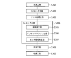
- a cleaning process including a rinse process, a pre-clean process, and a subsequent rinse process is executed (S301).
- the valve 78a of the rinse treatment liquid supply mechanism 78 is opened, whereby the rinse treatment liquid is supplied to the surface of the substrate 2 through the discharge port 72 of the third nozzle 70.
- a pre-cleaning process is performed.
- the valve 77a of the cleaning processing liquid supply mechanism 77 is opened, whereby the cleaning processing liquid is supplied to the surface of the substrate 2 through the discharge port 72 of the third nozzle 70.
- the rinse treatment liquid is supplied to the surface of the substrate 2 through the discharge port 72 of the third nozzle 70.
- any washing step S301 and the following steps may, unless otherwise specified, the substrate 2 is rotated in the first rotational direction R 1 by the substrate rotation holding mechanism 110.
- Pd plating process Next, a Pd plating process is performed (S302). This Pd plating process is executed as a displacement plating process while the substrate 2 after the pre-cleaning process is not dried. In this way, by performing the displacement plating process in a state where the substrate 2 is not dried, it is possible to prevent the copper on the surface to be plated of the substrate 2 from being oxidized and failing to perform a satisfactory displacement plating process. it can.
- the cup 105 is lowered by the elevating mechanism 164 to a position where the discharge port 129 and the outer peripheral edge of the substrate 2 face each other.
- the valve 76 a of the plating solution supply mechanism 76 is opened, whereby the plating solution containing Pd is discharged onto the surface of the substrate 2 at a desired flow rate through the discharge port 71 of the third nozzle 70.
- the treated plating solution is discharged from the discharge port 129 of the cup 105.
- the plating solution discharged from the discharge port 129 is collected and reused or discarded via the discharge mechanism 125.
- a rinsing process is performed as a pre-process performed prior to the Co plating process (S303).
- a rinse treatment liquid is supplied to the surface of the substrate 2 as a pretreatment liquid.
- the Co plating step S304 is performed as a chemical reduction plating treatment step.
- the Co plating step S304 includes a liquid replacement step S305 (first step), an incubation step S306 (second step), and a plating film growth step S307 (third step). Yes.
- the element forming the plating layer by precipitation is not limited to Co, and other elements may be simultaneously deposited.
- the plating solution used in the Co plating step contains ions of other elements in addition to Co ions, other elements may be deposited simultaneously with Co.
- the plating solution contains Co ions and P ions, and therefore a plating layer (CoP) containing not only Co but also P will be described.
- a plating layer obtained by the Co plating process is referred to as a “Co plating layer” even when an element other than Co is included in the plating layer.
- the liquid replacement step S305 is a step of replacing the rinse treatment liquid supplied to the substrate 2 in the above-described rinse treatment step S303 with the plating solution 35 that forms CoP.
- the incubation step S306 is a step of forming the initial Co plating layer 84 over the entire area of the Pd plating layer 83 described later after the liquid replacement step S305.
- the initial Co plating layer 84 is a Co plating layer 84 having a thickness of several tens of nm or less.
- the plating reaction is further advanced on the initial Co plating layer 84 formed in the incubation step S306 to form the Co plating layer 84 having a sufficient thickness, for example, a thickness of 100 nm or more. It is.
- FIG. 9A shows the substrate 2 after the Pd plating step S302 and the rinse treatment step S303 are performed.
- the substrate 2 has an insulating layer 81 made of an organic compound, a wiring 82 made of copper, and a Pd plating layer 83 provided so as to cover the wiring 82. Yes.
- the rinse treatment liquid 79 supplied in the rinse treatment step S303 is present on the substrate 2.
- the discharge port 46 of the second nozzle 45 is positioned closer to the center of the substrate 2 than the discharge ports 41 of the first nozzle 40, unless otherwise specified. is doing.
- the plating solution 35 heated to the first discharge temperature by the first heating means 60 ⁇ / b> A is discharged from the discharge ports 41 of the first nozzle 40 toward the surface of the substrate 2.
- the plating solution 35 heated to the second discharge temperature by the second heating unit 60B is discharged from the discharge port 46 of the second nozzle 45 toward the surface of the substrate 2.
- the plating solution 35 discharged from each discharge port 41 of the first nozzle 40 reaches a region within a predetermined range in the radial direction of the substrate 2 in the region on the substrate 2 as shown in FIG. To do. Further, the plating solution 35 discharged from the discharge port 46 of the second nozzle 45 reaches the substantially central portion of the substrate 2.
- the rinse treatment solution 79 present on the substrate 2 is It is replaced by a plating solution 35 that forms CoP. That is, the above-described liquid replacement step S305 is completed.
- the time required for the liquid replacement step S305 varies depending on the dimensions of the substrate 2 and the flow rate of the plating solution 35, but is, for example, about 1 second to 2 minutes.
- the plating solution 35 is discharged toward the substrate 2 using the first nozzle 40 and the second nozzle 45.
- the thickness of the Co plating layer 84 on the Pd plating layer 83 reaches a predetermined thickness, for example, 1 ⁇ m. That is, the plating film growth step S307 described above is completed.
- the cup 105 is lowered by the elevating mechanism 164 to a position where the discharge port 124 and the outer peripheral edge of the substrate 2 face each other. For this reason, the treated plating solution 35 is discharged from the discharge port 124 of the cup 105. The discharged plating solution 35 that has been discharged is collected and reused or discarded through the discharge mechanism 120.
- a cleaning step S308 including a rinsing process, a post-cleaning process, and a subsequent rinsing process is performed on the surface of the substrate 2 that has been subjected to the Co plating process. Since this cleaning step S308 is substantially the same as the above-described cleaning step S301, detailed description thereof is omitted.
- a drying process for drying the substrate 2 is performed (S309).
- the turntable 112 when the turntable 112 is rotated, the liquid adhering to the substrate 2 is blown outward by centrifugal force, thereby drying the substrate 2. That is, the turntable 112 may have a function as a drying mechanism that dries the surface of the substrate 2.
- the surface of the substrate 2 is first subjected to Pd plating by displacement plating, and then Co plating by chemical reduction plating.
- the substrate 2 may be transported to another plating processing apparatus 20 for Au plating processing.
- another plating processing apparatus 20 the surface of the substrate 2 is subjected to Au plating processing by displacement plating.
- the Au plating treatment method is substantially the same as the above-described method for Pd plating treatment except that the plating solution and the cleaning solution are different, and thus detailed description thereof is omitted.
- the discharge mechanism 21 that discharges the plating solution 35 toward the substrate 2 includes a plurality of discharge ports 41 arranged in the radial direction of the substrate 2.
- One nozzle 40 and a second nozzle 45 including a discharge port 46 that can be positioned closer to the center of the substrate 2 than the discharge ports 41 of the first nozzle 40 are provided.
- the plating solution 35 can be supplied to the central portion of the substrate 2 by the second nozzle 45, and the first nozzle 40 is located on the peripheral side of the central portion of the substrate 2 in the region on the substrate 2.
- the plating solution 35 can be directly supplied to the predetermined region.
- the temperature of the plating solution 35 reaching the predetermined region can be increased as compared with the case where only the plating solution 35 passing through the central portion of the substrate 2 reaches the predetermined region. Thereby, it is possible to suppress the occurrence of a difference between the reaction condition of the plating solution 35 in the central portion of the substrate 2 and the reaction condition of the plating solution 35 in the peripheral portion of the substrate 2. Thereby, the thickness of the Co plating layer 84 formed on the substrate 2 can be made substantially uniform over the entire area of the substrate 2.
- the substrate 2 is rotated by the substrate rotation holding mechanism 110 during the plating process. Therefore, not only the plating solution 35 directly supplied from the first nozzle 40 but also the second nozzle 45 is discharged into a predetermined region located on the peripheral side of the center portion of the substrate 2 in the region on the substrate 2. It is conceivable that the plating solution 35 also reaches the plating solution 35 via the central portion of the substrate 2. In this case, the plating solution 35 directly supplied from the first nozzle 40 to the predetermined area is mixed with the plating liquid 35 passing through the central portion of the substrate 2, whereby the temperature of the plating liquid 35 in the predetermined area is increased. The temperature of the plating solution 35 (first discharge temperature) when discharged from the first nozzle 40 is considered to be lower.
- the plating solution supply mechanism 30 performs the plating in which the temperature (first discharge temperature) of the plating solution supplied to the first nozzle 40 is supplied to the second nozzle 45.
- the temperature is higher than the temperature of the liquid (second discharge temperature). Therefore, even when the plating solution 35 from the first nozzle 40 and the plating solution 35 from the second nozzle 45 are mixed in the predetermined region, the temperature of the mixed plating solution 35 and the second nozzle The difference between the temperature of the plating solution 35 reaching the center of the substrate 2 from 45 (second discharge temperature) can be suppressed. Thereby, the thickness of the Co plating layer 84 formed on the substrate 2 can be made substantially uniform over the entire area of the substrate 2 more reliably.
- each discharge port 41 of the 1st nozzle 40 is comprised so that the plating solution 35 may be directly supplied to the peripheral part vicinity of the board
- the thickness of the Co plating layer 84 formed on the substrate 2 can be made substantially uniform over the entire area of the substrate 2 more reliably.
- the discharge port 46 of the second nozzle 45 applies the plating solution 35 toward the substrate 2 along the inclined direction S 1 inclined from the normal direction N of the substrate 2.
- An inclined discharge port 46a configured to discharge is included.
- the inclination direction S 1 of the inclined discharge port 46 a corresponds to the first rotation direction R 1 of the substrate 2. For this reason, the impact which the plating solution 35 which reached
- FIG. 10 shows a plating solution directed toward the substrate 2 using a nozzle 100 having a vertical discharge port 101 configured to discharge the plating solution 35 along the normal direction N of the substrate 2 toward the center of the substrate 2. It is a figure which shows the case where 35 is discharged.
- the components of the moving speed of the plating solution 35 are all components in the vertical direction. For this reason, compared with the case of this Embodiment, the impact which the plating solution 35 which arrived at the center part of the board
- the state of the plating solution 35 existing on the substrate 2 becomes unstable at or near the center of the substrate 2.
- the amount of the plating solution 35 present on the substrate 2 decreases or the flow of the plating solution 35 becomes intense at or near the center of the substrate 2.
- the reducing agent in the plating solution 35 emits electrons to the Pd plating layer 83 of the substrate 2, and these electrons are converted to metal ions (for example, Co ions) on the Pd plating layer 83. ) Is received, metal (Co) is deposited on the Pd plating layer 83.
- metal (Co) is deposited on the Pd plating layer 83.
- some layer for transferring electrons is formed between the plating solution 35 and the Pd plating layer 83.
- an electric double layer formed by forming positive and negative charged particles in pairs at the interface and arranging them in a layered manner is considered. In this case, in order to quickly transfer and receive electrons, it is important to stably maintain a layer for transferring and receiving electrons.
- the state of the plating solution 35 existing on the substrate 2 is unstable in the central portion of the substrate 2 or in the vicinity of the central portion.
- the layer for transferring and receiving electrons becomes unstable, and as a result, the speed of transferring and receiving electrons decreases, or the transfer of electrons cannot be performed.
- the thickness of the Co plating layer 84 formed at or near the center of the substrate 2 is thinner than the thickness of the Co plating layer 84 formed at other regions of the substrate. It can be considered.
- the Co plating layer 84 is not formed at the center of the substrate 2.
- the plating solution 35 is discharged toward the central portion of the substrate 2 using the inclined discharge port 46a, thereby reaching the central portion of the substrate 2.
- the impact of the liquid 35 on the substrate 2 can be weakened.
- the layer for transferring and receiving electrons can be stably maintained, so that the transfer of electrons between the plating solution 35 and the Pd plating layer 83 can be performed quickly.
- This can prevent the thickness of the Co plating layer 84 formed at the center of the substrate 2 from becoming thinner than the thickness of the Co plating layer 84 formed in other regions of the substrate.
- the inclined discharge port 46a the impact of the plating solution 35 on the substrate 2 can be weakened without reducing the discharge flow rate of the plating solution 35.
- the plating solution supply mechanism 30 stores a supply tank 31 that stores the plating solution 35, and tank heating means that heats the plating solution 35 in the supply tank 31 to a storage temperature. 50, a first supply pipe 33A for supplying the plating solution 35 in the supply tank 31 to the first nozzle 40, and a plating solution 35 attached to the first supply pipe 33A and supplied to the first nozzle 40 at the first discharge temperature.
- the first heating means 60A for heating the first, the second supply pipe for supplying the plating solution 35 of the supply tank 31 to the second nozzle 45, and the plating solution attached to the second supply pipe 33B and supplied to the second nozzle 45 The example which has the 2nd heating means 60B which heats 35 to 2nd discharge temperature was shown. However, the present invention is not limited to this, as long as it is realized that the temperature of the plating solution 35 supplied to the first nozzle 40 is higher than the temperature of the plating solution 35 supplied to the second nozzle 45.
- Various configurations of the plating solution supply mechanism 30 may be employed.
- the tank heating means 50 for heating the plating solution 35 in the supply tank 31 to the storage temperature may not be provided.
- the normal temperature plating solution 35 reaches the first heating means 60A and the second heating means 60B. Then, the plating solution 35 is heated to the first discharge temperature by the first heating means 60A, and the plating solution 35 is heated to the second discharge temperature by the second heating means 60B.
- the second heating means 60B may not be provided.
- the above-described storage temperature realized by the tank heating means 50 is set to be higher than the plating temperature. That is, the tank heating means 50 heats the plating solution 35 in the supply tank 31 to a temperature higher than the plating temperature.
- the temperature of the plating solution 35 discharged from the second nozzle 45 can be set to a predetermined temperature equal to or higher than the plating temperature.
- the temperature of the plating solution 35 supplied to the first nozzle 40 can be made higher than the temperature of the plating solution 35 supplied to the second nozzle 45 by the first heating means 60A.
- the plating solution supply mechanism 30 supplies the first supply tank 31 ⁇ / b> A and the second supply tank 31 ⁇ / b> B storing the plating solution 35 and the plating solution 35 in the first supply tank 31 ⁇ / b> A to the first nozzle 40.
- the first supply pipe 33A to be supplied, the second supply pipe 33B to supply the plating solution 35 in the second supply tank 31B to the second nozzle 45, and the plating solution 35 in the first supply tank 31A are heated to the first storage temperature.
- the tank first heating means 50A and the tank second heating means 50B for heating the plating solution 35 in the second supply tank 31B to the second storage temperature may be provided.
- first tank heating means 50A and the tank heating means 50B differ only in the target temperature, and the other points are substantially the same as the tank heating means 50 shown in FIG. Regarding the first tank heating means 50A and the tank heating means 50B shown in FIG. 11, the same parts as those of the tank heating means 50 shown in FIG.
- the tank first heating means 50 ⁇ / b> A and the tank second heating means 50 ⁇ / b> B are controlled by the control mechanism 160 so that the first storage temperature is higher than the second storage temperature. .
- the 1st storage temperature and the 2nd storage temperature are set so that it may become higher than the above-mentioned plating temperature. For this reason, the temperature of the plating solution 35 supplied to the first nozzle 40 and the second nozzle 45 can be made higher than the plating temperature, and the temperature of the plating solution 35 supplied to the first nozzle 40 is The temperature of the plating solution 35 supplied to the second nozzle 45 can be made higher.
- the plating solution supply mechanism 30 may further include a first heating means 60A and a second heating means 60B.
- the plating solution 35 is heated in two stages by the tank heating means 50A and 50B and the heating means 60A and 60B, as in the case of the embodiment shown in FIG. For this reason, the temperature of the plating solution 35 stored in each of the first supply tank 31A and the second supply tank 31B can be set lower than the plating temperature.
- the discharge port 46 of the second nozzle 45 discharges the plating solution 35 toward the substrate 2 along the inclined direction S 1 inclined from the normal direction N of the substrate 2.
- the example including the inclined discharge port 46a configured to do is shown.
- the present invention is not limited to this, and the discharge port 46 of the second nozzle 45 has a vertical discharge port 46 b configured to discharge the plating solution 35 toward the substrate 2 along the normal direction N of the substrate 2. Further, it may be included.
- 12 is a plan view showing a second nozzle 45 having a discharge port 46 further including a vertical discharge port 46b
- FIG. 13 is a cross-sectional view of the second nozzle 45 shown in FIG. 12 as viewed from the XIII-XIII direction. is there.
- the vertical discharge port 46 b discharges the plating solution 35 along a direction S 2 parallel to the normal direction N of the substrate 2.
- a second supply pipe 33B (1) for an inclined discharge port is connected to the inclined discharge port 46a, and a second supply pipe 33B (2) for a vertical discharge port is connected to the vertical discharge port 46b.
- Is connected Is connected.
- the second supply pipe 33B (1) for the inclined discharge port, the second supply pipe 33B (2) for the vertical discharge port, and the second supply pipe 33B are connected to the second supply pipe 33B.
- Closing means for selectively supplying the plating solution 35 in the pipe 33B to either the second supply pipe 33B (1) for the inclined discharge port or the second supply pipe 33B (2) for the vertical discharge port is provided. ing.
- This closing means is controlled by the control mechanism 160. Accordingly, by controlling the closing means by the control mechanism 160, the supply of the plating solution 35 to either the inclined discharge port 46a or the vertical discharge port 46b can be stopped. In other words, the closing means can close either the inclined discharge port 46 a or the vertical discharge port 46 b based on control from the control mechanism 160.
- the discharge port 46 of the second nozzle 45 further includes the above-described vertical discharge port 46b
- the following effects can be obtained by properly using the inclined discharge port 46a and the vertical discharge port 46b depending on the situation.
- the plating liquid 35 is discharged toward the substrate 2 using the vertical discharge port 46b of the second nozzle 45.
- the plating solution 35 is discharged toward the substrate 2 using the inclined discharge port 46a of the second nozzle 45.
- the impact given to the substrate 2 by the plating solution 35 that has reached the substrate 2 can be increased, whereby the rinse treatment solution on the substrate 2 is replaced with the plating solution 35. Can be promoted.
- the impact given to the substrate 2 by the plating solution 35 that has reached the substrate 2 can be weakened, as in the case of the present embodiment described above. Accordingly, it is possible to prevent the initial Co plating layer 84 from being formed and the Co plating layer 84 from being hindered by an impact.
- the example in which the first nozzle 40 includes a plurality of discharge ports 41 arranged along the radial direction of the substrate 2 has been shown.
- the first nozzle 40 can directly supply the plating solution 35 to a region within a predetermined range in the radial direction of the substrate 2 in the region on the substrate 2, a specific form of the first nozzle 40.
- the first nozzle 40 may include a slit-like discharge port 42 extending along the radial direction of the substrate 2.
- the first nozzle 40 may be configured by arranging a plurality of independent nozzles along the radial direction of the substrate 2.
- the discharge port 41 or the discharge port 42 is formed on the substrate 2 along the inclined direction inclined from the normal direction N of the substrate 2. You may be comprised so that the plating solution 35 may be discharged toward. Thereby, it is possible to weaken the impact when the plating solution 35 discharged from the first nozzle 40 collides with the substrate 2. This makes it possible to more stably maintain a layer for transferring electrons between the plating solution 35 and the Pd plating layer 83 during the incubation step S306 and the plating film growth step S307.
- the discharge port 46 of the second nozzle 45 is positioned closer to the center of the substrate 2 than the discharge ports 41 of the first nozzle 40.
- the second nozzle 45 discharges the plating solution 35 toward the substrate 2.
- the present invention is not limited to this, and the control mechanism 160 causes the second nozzle 45 to discharge the plating solution 35 toward the substrate 2 while the second nozzle 45 moves from the center position to the peripheral position.
- the two nozzles 45 and the arm 49 may be controlled.
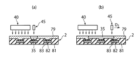
- FIGS. 15A and 15B are diagrams showing an example in which the plating solution 35 is discharged toward the substrate 2 while the second nozzle 45 is moving from the center position to the peripheral position in the above-described liquid replacement step S305. It is.
- FIG. 15 (b) the direction from the center position to peripheral positions is represented by arrow D 1.
- the second nozzle 45 discharges the plating solution 35 toward the center of the substrate 2 at the center position.
- the second nozzle 45 discharges the plating solution 35 toward the substrate 2 while the second nozzle 45 moves from the center position to the peripheral position.
- the rinsing solution 79 on the substrate 2 is sequentially replaced with the plating solution 35 in the direction from the central portion to the peripheral portion of the substrate 2.
- the moving speed of the second nozzle 45 is included in the velocity component of the discharged plating solution 35.
- the force by which the plating solution 35 pushes the rinsing treatment liquid 79 toward the peripheral edge of the substrate 2 is strengthened, whereby the rinsing treatment solution 79 on the substrate 2 is more efficiently replaced with the plating solution 35.
- the second nozzle 45 moves toward the substrate 2 while the second nozzle 45 moves from the center position to the peripheral position.
- the example in which the second nozzle 45 and the arm 49 are controlled by the control mechanism 160 so as to discharge 35 is shown.
- the present invention is not limited to this, and the control mechanism 160 causes the second nozzle 45 to discharge the plating solution 35 toward the substrate 2 while the second nozzle 45 is moving from the peripheral position to the center position.
- the two nozzles 45 and the arm 49 may be controlled.
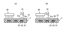
- the second nozzle 45 discharges the plating solution 35 toward the substrate 2 while the second nozzle 45 moves from the peripheral position to the center position. It is a figure which shows an example. In FIG. 16 (a) (b), the direction toward the center position from the edge position is indicated by the arrow D 2.
- the second nozzle 45 discharges the plating solution 35 toward the substrate 2 while the second nozzle 45 is moving from the peripheral position to the center position
- the second nozzle 45 is included in the velocity component of the discharged plating solution.
- a speed component corresponding to a moving speed of 45 which is a horizontal speed component from the peripheral edge of the substrate 2 toward the center, is included.
- the substrate 2 is rotated by the substrate rotation holding mechanism 110. For this reason, it is considered that the plating solution 35 already existing on the substrate 2 is moving from the central portion of the substrate 2 toward the peripheral portion based on the centrifugal force.
- the velocity component in the horizontal direction of the plating solution 35 discharged from the second nozzle 45 toward the substrate 2 and the velocity component in the horizontal direction of the plating solution 35 already existing on the substrate 2 are contradictory. It has become.
- the plating solution 35 discharged from the second nozzle 45 and the plating solution 35 already present on the substrate 2 collide with each other. It is conceivable that the flow is stagnated, and as a result, a liquid deposit portion 35 a of the plating solution 35 is formed on the substrate 2.
- the present invention is not limited to this, and also in the plating film growth step S307 described above, the second nozzle 45 moves toward the substrate 2 while the second nozzle 45 moves from the peripheral position to the center position.
- the second nozzle 45 and the arm 49 may be controlled by the control mechanism 160 so as to discharge the gas. Thereby, the growth of the Co plating layer 84 can be promoted.
- the control mechanism 160 discharges the plating solution 35 toward the substrate 2 while the second nozzle 45 is moving from the center position to the peripheral position, and the incubation step S306.
- the second nozzle 45 and the arm 49 are controlled so that the second nozzle 45 discharges the plating solution 35 toward the substrate 2 while the second nozzle 45 is moving from the peripheral position to the center position.
- the substrate 2 is an example that is rotated in the first rotational direction R 1 by the substrate rotation holding mechanism 110.
- the present invention is not limited to this, and the substrate 2 may be rotated in the second rotation direction R 2 depending on the situation.
- the control The mechanism 160 may control the substrate rotation holding mechanism 110 and the second nozzle 45.
- inclined discharge opening 46a corresponds to the first rotational direction R 1 as described above
- the second rotational direction R 2 is a direction opposite the first rotational direction R 1. Therefore, when rotating the substrate 2 in the second rotational direction R 2, the moving speed of the substrate 2 in the horizontal direction of the region where the plating solution 35 collide, large difference between the moving speed of the plating solution 35 in the horizontal direction It has become.
- the plating solution 35 that has collided with the substrate 2 has on the substrate 2
- the impact can be strengthened.
- the force with which the plating solution 35 pushes the rinsing treatment liquid 79 can be increased, whereby the rinsing treatment solution 79 on the substrate 2 can be replaced with the plating solution 35 more efficiently.
- the control mechanism 160, the second nozzle 45 ejects the plating solution 35 toward the substrate 2 while the substrate 2 when the liquid replacement step S305 is rotating in the second rotational direction R 2, the incubation step S306 the second nozzle 45 to eject the plating solution 35 toward the substrate 2, which controls the substrate rotating holding mechanism 110 and the second nozzle 45 while the substrate 2 is rotated in the first rotational direction R 1 when.
- the impact of the plating solution 35 on the substrate 2 at the time of the liquid replacement step S305 can be increased, and the impact of the plating solution 35 on the substrate 2 at the time of the incubation step S306 can be reduced.
- both the liquid replacement step S305 and the incubation step S306 can be efficiently performed.
- the substrate 2 is supplied from both the first nozzle 40 and the second nozzle 45 in all the steps of the liquid replacement step S305, the incubation step S306, and the plating film growth step S307.
- An example in which the plating solution 35 is discharged is shown.
- the present invention is not limited to this.
- the plating solution 35 may be discharged toward the substrate 2 using only the second nozzle 45.
- the plating solution 35 may be discharged toward the substrate 2 using only the first nozzle 40.
- the plating solution 35 discharged from the second nozzle 45 is applied to the substrate 2 during the incubation step S306 by using the inclined discharge port 46a of the second nozzle 45.
- An example where the impact is weakened is shown.
- specific means for reducing the impact of the plating solution 35 discharged from the second nozzle 45 on the substrate 2 is not particularly limited.
- the second nozzle 45 is adjusted during the incubation step S306 by appropriately adjusting the second valve 32B of the plating solution supply mechanism 30. , The discharge speed of the plating solution 35 discharged toward the substrate 2 in the normal direction N of the substrate 2 can be reduced.
- the discharge speed in the normal direction N of the substrate 2 of the plating solution 35 discharged from the second nozzle 45 toward the substrate 2 during the incubation step S306 is such that the second nozzle is discharged during the liquid replacement step S305.
- the control mechanism 160 controls the plating solution supply mechanism 30 so that the plating solution 35 discharged from 45 toward the substrate 2 is smaller than the discharge speed in the normal direction N of the substrate 2.
- the plating solution 35 used is not limited to the CoP plating solution, and various plating solutions 35 can be used.
- the chemical reduction type plating solution 35 various plating solutions 35 such as a CoWB plating solution, a CoWP plating solution, a CoB plating solution, or a NiP plating solution may be used.
- the first nozzle 40 includes a plurality of discharge ports 41 arranged along the radial direction of the substrate 2, or has a slit shape extending along the radial direction of the substrate 2.
- An example including the discharge port 42 was shown.
- the present invention is not limited to this, and the first nozzle 40 may include only one circular discharge port 41.
- the discharge mechanism 21 includes a first nozzle 40 including a discharge port 41 that discharges the plating solution 35 toward the substrate 2, and the central portion of the substrate 2 rather than the discharge port 41 of the first nozzle 40.
- the plating solution supply mechanism 30 uses the plating solution in which the temperature of the plating solution 35 supplied to the first nozzle 40 is supplied to the second nozzle 45.
- the temperature is higher than 35.
- Example 1 The CoP plating solution was discharged toward the substrate 2 using the first nozzle 40 having a plurality of discharge ports 41 and the second nozzle 45 located at the center of the substrate 2. At this time, the temperature of the plating solution supplied to the first nozzle 40 was 90 ° C., and the temperature of the plating solution supplied to the second nozzle 45 was 80 ° C. Then, the temperature of the substrate 2 was measured along the radial direction of the substrate 2. The results are shown in FIG. In FIG. 18, the horizontal axis indicates the position on the substrate 2, and the vertical axis indicates the measured temperature. In the horizontal axis of FIG. 18, “0” corresponds to the center portion of the substrate 2, and “ ⁇ 150” corresponds to the peripheral portion of the substrate 2.
- the temperature of the substrate 2 is substantially reduced over the entire area of the substrate 2. It was possible to make it uniform.
Landscapes
- Chemical & Material Sciences (AREA)
- General Chemical & Material Sciences (AREA)
- Chemical Kinetics & Catalysis (AREA)
- Engineering & Computer Science (AREA)
- Materials Engineering (AREA)
- Mechanical Engineering (AREA)
- Metallurgy (AREA)
- Organic Chemistry (AREA)
- Chemically Coating (AREA)
- Electrodes Of Semiconductors (AREA)
Abstract
Description
前記吐出機構にめっき液を供給するめっき液供給機構と、前記吐出機構および前記めっき液供給機構を制御する制御機構と、を備え、前記吐出機構は、前記基板に向けてめっき液を吐出する吐出口を含む第1ノズルと、前記第1ノズルの吐出口よりも前記基板の中心部に近接するよう位置することができる吐出口を含む第2ノズルと、を有し、前記めっき液供給機構は、前記第1ノズルに供給されるめっき液の温度が前記第2ノズルに供給されるめっき液の温度よりも高くなるよう構成されているめっき処理装置が提供される。
図1に示すように、めっき処理システム1は、基板2(ここでは、半導体ウエハ)を複数枚(たとえば、25枚)収容するキャリア3を載置し、基板2を所定枚数ずつ搬入及び搬出するための基板搬入出室5と、基板2のめっき処理や洗浄処理などの各種の処理を行うための基板処理室6と、を含んでいる。基板搬入出室5と基板処理室6とは、隣接して設けられている。
基板搬入出室5は、キャリア載置部4、搬送装置8を収容した搬送室9、基板受渡台10を収容した基板受渡室11を有している。基板搬入出室5においては、搬送室9と基板受渡室11とが受渡口12を介して連通連結されている。キャリア載置部4は、複数の基板2を水平状態で収容するキャリア3を複数個載置する。搬送室9では、基板2の搬送が行われ、基板受渡室11では、基板処理室6との間で基板2の受け渡しが行われる。
また基板処理室6は、中央部において前後に伸延する基板搬送ユニット13と、基板搬送ユニット13の一方側および他方側において前後に並べて配置され、基板2にめっき液を供給してめっき処理を行う複数のめっき処理装置20と、を有している。
以下、図2および図3を参照して、めっき処理装置20について説明する。図2は、めっき処理装置20を示す側面図であり、図3は、めっき処理装置20を示す平面図である。
このうち基板回転保持機構110は、図2および図3に示すように、ケーシング101内で上下に伸延する中空円筒状の回転軸111と、回転軸111の上端部に取り付けられたターンテーブル112と、ターンテーブル112の上面外周部に設けられ、基板2を支持するウエハチャック113と、回転軸111を回転駆動する回転機構162と、を有している。このうち回転機構162は、制御機構160により制御され、回転機構162によって回転軸111が回転駆動され、これによって、ウエハチャック113により支持されている基板2が回転される。
次に、基板2に向けてめっき液などを吐出する吐出機構21について説明する。吐出機構21は、基板2に向けてCoPめっき液などの化学還元タイプのめっき液を吐出する第1ノズル40および第2ノズル45を含んでいる。化学還元タイプのめっき液は、めっき液供給機構30から第1ノズル40および第2ノズル45に供給される。第1ノズル40および第2ノズル45の詳細については後述する。
図2および図3に示すように、第1ノズル40は、複数の吐出口41を含んでいる。また第1ノズル40は、アーム44の先端部に取り付けられている。アーム44は、上下方向に延伸可能であるとともに回転機構165により回転駆動される支持軸43に固定されている。
次に第2ノズル45について説明する。図2および図3に示すように、第2ノズル45は吐出口46を含んでいる。また第2ノズル45は、アーム49の先端部に取り付けられており、このアーム49は、基板2の半径方向(図2および図3において矢印Dにより示される方向)において進退自在となるよう構成されている。このため、第2ノズル45は、第2ノズル45の吐出口46が第1ノズル40の各吐出口41よりも基板2の中心部に近接する中心位置と、中心位置よりも周縁側にある周縁位置との間で移動可能となっている。なお図3において、中心位置にある第2ノズルが符号45’で示されており、周縁位置にある第2ノズルが符号45”で示されている。
次に、吐出機構21の第1ノズル40および第2ノズル45に、CoPめっき液などの化学還元タイプのめっき液を供給するめっき液供給機構30について説明する。図4は、めっき液供給機構30を示す図である。
このため、めっき液35が供給タンク31内でめっき温度以上の温度に加熱される場合に比べて、供給タンク31内のめっき液35中で還元剤の失活や成分の蒸発を防ぐことができる。これによって、めっき液35の寿命を長くすることができる。
また、供給タンク31においてめっき液35が常温で貯留され、その後に第1加熱手段60Aおよび第2加熱手段60Bによってめっき温度以上の温度に加熱される場合に比べて、めっき液35を小さいエネルギーで素早くめっき温度以上の温度に加熱することができる。このことにより、金属イオンの析出を抑制することができる。
タンク用加熱手段50は、図4に示すように、供給タンク31の近傍でめっき液35の循環経路を形成する循環管52と、循環管52に取り付けられ、めっき液35を貯留温度に加熱するヒータ53と、循環管52に挿入され、めっき液35を循環させるポンプ56と、を有している。タンク用加熱手段50を設けることにより、供給タンク31内のめっき液35を供給タンク31近傍で循環させながら上述の貯留温度まで加熱することができる。
次に図5を参照して、第1加熱手段60Aについて説明する。第1加熱手段60Aは、タンク用加熱手段50によって貯留温度まで加熱されためっき液35を、さらに第1吐出温度まで加熱するためのものである。この第1加熱手段60Aは、図5に示すように、所定の伝熱媒体を、第1吐出温度、または第1吐出温度よりも高い温度に加熱する第1温度媒体供給手段61Aと、第1供給管33Aに取り付けられ、第1温度媒体供給手段61Aからの伝熱媒体の熱を第1供給管33A内のめっき液35に伝導させる温度調節器62と、を有している。また図5に示すように、第1ノズル40の内部に至るよう設けられ、第1ノズル40内に位置する第1供給管33Aを通るめっき液35を第1吐出温度で保持するための温度保持器65がさらに設けられていてもよい。
次に図6を参照して、第2加熱手段60Bについて説明する。第2加熱手段60Bは、タンク用加熱手段50によって貯留温度まで加熱されためっき液35を、さらに第2吐出温度まで加熱するためのものである。この第2加熱手段60Bは、図6に示すように、所定の伝熱媒体を第2吐出温度または第2吐出温度よりも高い温度に加熱する第2温度媒体供給手段61Bと、第2供給管33Bに取り付けられ、第2温度媒体供給手段61Bからの伝熱媒体の熱を第2供給管33B内のめっき液35に伝導させる温度調節器62と、を有している。また図6に示すように、第2ノズル45の内部に至るよう設けられ、第2ノズル45内に位置する第2供給管33Bを通るめっき液35を第2吐出温度で保持するための温度保持器65がさらに設けられていてもよい。
次に、基板2から飛散しためっき液や洗浄液などを排出する液排出機構120,125,130について、図2を参照して説明する。図2に示すように、ケーシング101内には、昇降機構164により上下方向に駆動され、排出口124,129,134を有するカップ105が配置されている。液排出機構120,125,130は、それぞれ排出口124,129,134に集められる液を排出するものとなっている。
図2に示すように、めっき処理装置20は、基板2の裏面に処理液を供給する裏面処理液供給機構145と、基板2の裏面に気体を供給する裏面ガス供給機構150と、をさらに有していてもよい。
本実施の形態において、めっき処理システム1およびめっき処理装置20は、記憶媒体161に記録されためっき処理プログラムに従って、基板2にめっき処理を施すよう駆動制御される。以下の説明では、はじめに、一のめっき処理装置20で基板2にPdめっき処理を置換めっきにより施し、その後、Coめっき処理を化学還元めっきにより施す方法について、図8および図9(a)~(e)を参照して説明する。
はじめに、基板搬入工程および基板受入工程が実行される。まず、基板搬送ユニット13の基板搬送装置14を用いて、1枚の基板2を基板受渡室11から一のめっき処理装置20に搬入する。めっき処理装置20においては、はじめに、カップ105が所定位置まで降下される。次に、搬入された基板2がウエハチャック113により支持される。その後、排出口134と基板2の外周端縁とが対向する位置までカップ105が昇降機構164により上昇させられる。
次に、リンス処理、前洗浄処理およびその後のリンス処理を含む洗浄工程が実行される(S301)。はじめに、リンス処理液供給機構78のバルブ78aが開かれ、これによって、リンス処理液が基板2の表面に第3ノズル70の吐出口72を介して供給される。次に、前洗浄工程が実行される。はじめに、洗浄処理液供給機構77のバルブ77aが開かれ、これによって、洗浄処理液が基板2の表面に第3ノズル70の吐出口72を介して供給される。その後、上述の場合と同様にして、リンス処理液が基板2の表面に第3ノズル70の吐出口72を介して供給される。処理後のリンス処理液や洗浄処理液は、カップ105の排出口134および処理液排出機構130を介して廃棄される。なお洗浄工程S301および以下の各工程のいずれにおいても、特に言及しない限り、基板2は基板回転保持機構110により第1回転方向R1において回転されている。
次に、Pdめっき工程が実行される(S302)。このPdめっき工程は、前洗浄工程後の基板2が乾燥されていない状態の間に、置換めっき処理工程として実行される。このように、基板2が乾燥していない状態で置換めっき処理工程を実行することで、基板2の被めっき面の銅などが酸化してしまい良好に置換めっき処理できなくなるのを防止することができる。
次に、Coめっき工程に先立って実施される前処理として、例えばリンス処理工程が実行される(S303)。このリンス処理工程S303においては、前処理液として例えばリンス処理液が基板2の表面に供給される。
その後、上述の工程S301~303が実行されたのと同一のめっき処理装置20において、Coめっき工程が実行される(S304)。このCoめっき工程S304は、化学還元めっき処理工程として実行される。このCoめっき工程S304は、図8に示すように、液置換工程S305(第1工程)と、インキュベーション工程S306(第2工程)と、めっき膜成長工程S307(第3工程)と、を含んでいる。
第1ノズル40および第2ノズル45を用いて基板2に向けてめっき液35を吐出することにより、図9(b)に示すように、基板2上に存在していたリンス処理液79が、CoPを形成するめっき液35によって置換される。すなわち、上述の液置換工程S305が完了する。液置換工程S305に要する時間は、基板2の寸法やめっき液35の流量によって異なるが、例えば1秒~2分程度となっている。
引き続き第1ノズル40および第2ノズル45を用いて基板2に向けてめっき液35を吐出する。これによって、図9(c)に示すように、Pdめっき層83上に初期のCoめっき層84が部分的に形成される。さらに基板2に向けてめっき液35を吐出し続けると、図9(d)に示すように、Pdめっき層83上の全域にわたって初期のCoめっき層84が形成される。すなわち、上述のインキュベーション工程S306が完了する。
引き続き第1ノズル40および第2ノズル45を用いて基板2に向けてめっき液35を吐出する。これによって、図9(e)に示すように、Pdめっき層83上のCoめっき層84の厚みが、所定の厚み、例えば1μmに到達する。すなわち、上述のめっき膜成長工程S307が完了する。
次に、Coめっき処理が施された基板2の表面に対して、リンス処理、後洗浄処理およびその後のリンス処理を含む洗浄工程S308が実行される。この洗浄工程S308は、上述の洗浄工程S301と略同一であるので、詳細な説明は省略する。
その後、基板2を乾燥させる乾燥工程が実行される(S309)。例えば、ターンテーブル112を回転させることにより、基板2に付着している液体が遠心力により外方へ飛ばされ、これによって基板2が乾燥される。すなわち、ターンテーブル112が、基板2の表面を乾燥させる乾燥機構としての機能を備えていてもよい。
ここで本実施の形態によれば、上述のように、基板2に向けてめっき液35を吐出する吐出機構21は、基板2の半径方向に沿って並べられた複数の吐出口41を含む第1ノズル40と、第1ノズル40の各吐出口41よりも基板2の中心部に近接するよう位置することができる吐出口46を含む第2ノズル45と、を有している。このため、第2ノズル45によって基板2の中心部にめっき液35を供給することができ、かつ、第1ノズル40によって、基板2上の領域のうち基板2の中心部よりも周縁側にある所定領域にめっき液35を直接供給することができる。このため、基板2の中心部を経由しためっき液35のみが上記所定領域に到達する場合に比べて、上記所定領域に到達するめっき液35の温度を高くすることができる。これによって、基板2の中心部におけるめっき液35の反応条件と、基板2の周縁部におけるめっき液35の反応条件との間に差が生じることを抑制することができる。このことにより、基板2に形成されるCoめっき層84の厚みを、基板2の全域にわたって略均一にすることができる。
また本実施の形態によれば、上述のように、第2ノズル45の吐出口46は、基板2の法線方向Nから傾斜した傾斜方向S1に沿って基板2に向けてめっき液35を吐出するよう構成された傾斜吐出口46aを含んでいる。また、傾斜吐出口46aの傾斜方向S1は、基板2の第1回転方向R1に対応している。このため、基板2の中心部に到達しためっき液35が基板2に与える衝撃を弱めることができる。これによって、基板2の中心部または中心部近傍において上述のインキュベーション工程S306およびめっき膜成長工程S307が阻害されることを防ぐことができる。
なお本実施の形態において、めっき液供給機構30が、めっき液35を貯留する供給タンク31と、供給タンク31内のめっき液35を貯留温度に加熱するタンク用加熱手段50と、供給タンク31のめっき液35を第1ノズル40へ供給する第1供給管33Aと、第1供給管33Aに取り付けられ、第1ノズル40に供給されるめっき液35を第1吐出温度に加熱する第1加熱手段60Aと、供給タンク31のめっき液35を第2ノズル45へ供給する第2供給管と、第2供給管33Bに取り付けられ、第2ノズル45に供給されるめっき液35を第2吐出温度に加熱する第2加熱手段60Bと、を有する例を示した。しかしながら、これに限られることはなく、第1ノズル40に供給されるめっき液35の温度が第2ノズル45に供給されるめっき液35の温度よりも高くなるということが実現される限りにおいて、めっき液供給機構30の様々な構成が採用され得る。
また本実施の形態において、第2ノズル45の吐出口46が、基板2の法線方向Nから傾斜した傾斜方向S1に沿って基板2に向けてめっき液35を吐出するよう構成された傾斜吐出口46aを含む例を示した。しかしながら、これに限られることはなく、第2ノズル45の吐出口46は、基板2の法線方向Nに沿って基板2に向けてめっき液35を吐出するよう構成された垂直吐出口46bをさらに含んでいてもよい。図12は、垂直吐出口46bをさらに含む吐出口46を有する第2ノズル45を示す平面図であり、図13は、図12に示す第2ノズル45をXIII-XIII方向から見た断面図である。
また本実施の形態において、第1ノズル40が、基板2の半径方向に沿って並べられた複数の吐出口41を含む例を示した。しかしながら、基板2上の領域のうち基板2の半径方向における所定範囲内の領域に対して第1ノズル40がめっき液35を直接供給することができる限りにおいて、第1ノズル40の具体的な形態が限定されることはない。例えば図14に示すように、第1ノズル40は、基板2の半径方向に沿って延びるスリット状の吐出口42を含んでいてもよい。若しくは、図示はしないが、独立した複数のノズルを基板2の半径方向に沿って並べることにより第1ノズル40が構成されていてもよい。
また本実施の形態において、第2ノズル45の吐出口46が第1ノズル40の各吐出口41よりも基板2の中心部に近接するよう位置している状態で、第2ノズル45が基板2に向けてめっき液35を吐出する例を示した。しかしながら、これに限られることはなく、第2ノズル45が中心位置から周縁位置へ移動している間に第2ノズル45が基板2に向けてめっき液35を吐出するよう、制御機構160が第2ノズル45およびアーム49を制御してもよい。
なお上述の制御方法の第1の変形例において、第2ノズル45が中心位置から周縁位置へ移動している間に第2ノズル45が基板2に向けてめっき液35を吐出するよう、制御機構160によって第2ノズル45およびアーム49が制御される例を示した。しかしながら、これに限られることはなく、第2ノズル45が周縁位置から中心位置へ移動している間に第2ノズル45が基板2に向けてめっき液35を吐出するよう、制御機構160によって第2ノズル45およびアーム49を制御してもよい。
また本実施の形態において、基板2が基板回転保持機構110により第1回転方向R1において回転されている例を示した。しかしながら、これに限られることはなく、状況に応じて基板2を第2回転方向R2において回転させてもよい。
また本実施の形態において、液置換工程S305、インキュベーション工程S306およびめっき膜成長工程S307の全ての工程において、第1ノズル40および第2ノズル45の両方から基板2に向けてめっき液35が吐出される例を示した。しかしながら、これに限られることはなく、液置換工程S305において少なくとも第2ノズル45が用いられ、インキュベーション工程S306において少なくとも第1ノズル40が用いられる限りにおいて、各工程において用いられる第1ノズル40および第2ノズル45を適宜決定することができる。例えば、液置換工程S305においては、第2ノズル45のみを用いて基板2に向けてめっき液35を吐出してもよい。またインキュベーション工程S306およびめっき膜成長工程S307においては、第1ノズル40のみを用いて基板2に向けてめっき液35を吐出してもよい。
また本実施の形態および各変形例において、第2ノズル45の傾斜吐出口46aを用いることにより、インキュベーション工程S306の時に第2ノズル45から吐出されためっき液35が基板2に与える衝撃が弱められる例を示した。しかしながら、第2ノズル45から吐出されためっき液35が基板2に与える衝撃を弱めるための具体的な手段が特に限られることはない。例えば、第2ノズル45の吐出口46が垂直吐出口46bのみを含む場合であっても、めっき液供給機構30の第2バルブ32Bを適宜調整することにより、インキュベーション工程S306の時に第2ノズル45から基板2に向けて吐出されるめっき液35の、基板2の法線方向Nにおける吐出速度を小さくすることができる。これによって、インキュベーション工程S306の時に第2ノズル45から吐出されためっき液35が基板2に与える衝撃を弱めることができる。この場合、好ましくは、インキュベーション工程S306の時に第2ノズル45から基板2に向けて吐出されるめっき液35の、基板2の法線方向Nにおける吐出速度が、液置換工程S305の時に第2ノズル45から基板2に向けて吐出されるめっき液35の、基板2の法線方向Nにおける吐出速度よりも小さくなるよう、制御機構160がめっき液供給機構30を制御する。これによって、液置換工程S305およびインキュベーション工程S306の両方を効率的に実施することができる。
複数の吐出口41を有する第1ノズル40と、基板2の中心部に位置する第2ノズル45とを用いて、基板2に向けてCoPめっき液を吐出した。この際、第1ノズル40に供給されるめっき液の温度を90℃とし、第2ノズル45に供給されるめっき液の温度を80℃とした。そして、基板2の温度を、基板2の半径方向に沿って測定した。結果を図18に示す。なお図18において、横軸は基板2上での位置を示しており、縦軸は測定された温度を示している。また図18の横軸において、「0」が基板2の中心部に対応しており、「±150」が基板2の周縁部に対応している。
基板2の中心部に位置する第2ノズル45のみを用いて、基板2に向けてCoPめっき液を吐出した。この際、第2ノズル45に供給されるめっき液の温度を80℃とした。そして、基板2の温度を、基板2の半径方向に沿って測定した。結果を、実施例1の結果と併せて図18に示す。
2 基板
20 めっき処理装置
21 吐出機構
30 めっき液供給機構
31 供給タンク
31A 第1供給タンク
31B 第2供給タンク
33A 第1供給管
33B 第2供給管
40 第1ノズル
41 吐出口
45 第2ノズル
46 吐出口
46a 傾斜吐出口
46b 垂直吐出口
50 タンク用加熱手段
50A 第1タンク用加熱手段
50B 第2タンク用加熱手段
60A 第1加熱手段
60B 第2加熱手段
110 基板回転保持機構
160 制御機構
161 記憶媒体
Claims (10)
- 基板にめっき液を供給してめっき処理を行うめっき処理装置において、
前記基板を保持して回転させる基板回転保持機構と、
前記基板回転保持機構に保持された前記基板に向けてめっき液を吐出する吐出機構と、
前記吐出機構にめっき液を供給するめっき液供給機構と、
前記吐出機構および前記めっき液供給機構を制御する制御機構と、を備え、
前記吐出機構は、前記基板に向けてめっき液を吐出する吐出口を含む第1ノズルと、前記第1ノズルの吐出口よりも前記基板の中心部に近接するよう位置することができる吐出口を含む第2ノズルと、を有し、
前記めっき液供給機構は、前記第1ノズルに供給されるめっき液の温度が前記第2ノズルに供給されるめっき液の温度よりも高くなるよう構成されていることを特徴とするめっき処理装置。 - 前記めっき液供給機構は、めっき液を貯留する供給タンクと、前記供給タンクのめっき液を前記第1ノズルへ供給する第1供給管と、前記第1供給管に取り付けられ、前記第1ノズルに供給されるめっき液を加熱する第1加熱手段と、前記供給タンクのめっき液を前記第2ノズルへ供給する第2供給管と、を有することを特徴とする請求項1に記載のめっき処理装置。
- 前記めっき液供給機構は、前記第2供給管に取り付けられ、前記第2ノズルに供給されるめっき液を加熱する第2加熱手段をさらに有し、
前記第1加熱手段および前記第2加熱手段は、前記第1ノズルに供給されるめっき液の温度が前記第2ノズルに供給されるめっき液の温度よりも高くなるよう構成されていることを特徴とする請求項2に記載のめっき処理装置。 - 前記めっき液供給機構は、前記供給タンク内のめっき液を加熱するタンク用加熱手段をさらに有することを特徴とする請求項2に記載のめっき処理装置。
- 前記タンク用加熱手段は、前記供給タンク内のめっき液の温度が、めっき液の自己反応が進行するめっき温度よりも低温になるよう構成されていることを特徴とする請求項4に記載のめっき処理装置。
- 前記めっき液供給機構は、前記供給タンク内のめっき液を加熱するタンク用加熱手段をさらに有することを特徴とする請求項3に記載のめっき処理装置。
- 前記タンク用加熱手段は、前記供給タンク内のめっき液の温度が、めっき液の自己反応が進行するめっき温度よりも低温になるよう構成されていることを特徴とする請求項6に記載のめっき処理装置。
- 前記めっき液供給機構は、めっき液を貯留する第1供給タンクおよび第2供給タンクと、前記第1供給タンクのめっき液を前記第1ノズルへ供給する第1供給管と、前記第2供給タンクのめっき液を前記第2ノズルへ供給する第2供給管と、前記第1供給タンク内のめっき液を加熱するタンク用第1加熱手段と、前記第2供給タンク内のめっき液を加熱するタンク用第2加熱手段と、を有し、
前記タンク用第1加熱手段および前記タンク用第2加熱手段は、前記第1ノズルに供給されるめっき液の温度が前記第2ノズルに供給されるめっき液の温度よりも高くなるよう構成されていることを特徴とする請求項1に記載のめっき処理装置。 - 基板にめっき液を供給してめっき処理を行うめっき処理方法において、
前記基板を基板回転保持機構上に配置することと、
前記基板に吐出機構を介してめっき液を吐出することと、を備え、
前記吐出機構は、前記基板に向けてめっき液を吐出する吐出口を含む第1ノズルと、前記第1ノズルの吐出口よりも前記基板の中心部に近接するよう位置することができる吐出口を含む第2ノズルと、を配置し、
前記第1ノズルから前記基板に向けて吐出されるめっき液の温度は、前記第2ノズルから前記基板に向けて吐出されるめっき液の温度よりも高いことを特徴とするめっき処理方法。 - めっき処理装置にめっき処理方法を実行させるためのコンピュータプログラムを格納した記憶媒体において、
前記めっき処理方法は、基板にめっき液を供給してめっき処理を行う方法であって、
基板を基板回転保持機構上に配置することと、
前記基板に吐出機構を介してめっき液を吐出することと、を備え、
前記吐出機構は、前記基板に向けてめっき液を吐出する吐出口を含む第1ノズルと、前記第1ノズルの吐出口よりも前記基板の中心部に近接するよう位置することができる吐出口を含む第2ノズルと、を配置し、
前記第1ノズルから前記基板に向けて吐出されるめっき液の温度は、前記第2ノズルから前記基板に向けて吐出されるめっき液の温度よりも高い、方法からなっていることを特徴とする記憶媒体。
Priority Applications (2)
| Application Number | Priority Date | Filing Date | Title |
|---|---|---|---|
| US14/129,623 US9505019B2 (en) | 2011-06-29 | 2012-06-04 | Plating apparatus, plating method and storage medium |
| KR1020137033423A KR101765570B1 (ko) | 2011-06-29 | 2012-06-04 | 도금 처리 장치, 도금 처리 방법 및 기억 매체 |
Applications Claiming Priority (2)
| Application Number | Priority Date | Filing Date | Title |
|---|---|---|---|
| JP2011144795A JP5634341B2 (ja) | 2011-06-29 | 2011-06-29 | めっき処理装置、めっき処理方法および記憶媒体 |
| JP2011-144795 | 2011-06-29 |
Publications (1)
| Publication Number | Publication Date |
|---|---|
| WO2013001985A1 true WO2013001985A1 (ja) | 2013-01-03 |
Family
ID=47423885
Family Applications (1)
| Application Number | Title | Priority Date | Filing Date |
|---|---|---|---|
| PCT/JP2012/064380 Ceased WO2013001985A1 (ja) | 2011-06-29 | 2012-06-04 | めっき処理装置、めっき処理方法および記憶媒体 |
Country Status (5)
| Country | Link |
|---|---|
| US (1) | US9505019B2 (ja) |
| JP (1) | JP5634341B2 (ja) |
| KR (1) | KR101765570B1 (ja) |
| TW (1) | TWI535888B (ja) |
| WO (1) | WO2013001985A1 (ja) |
Families Citing this family (10)
| Publication number | Priority date | Publication date | Assignee | Title |
|---|---|---|---|---|
| JP6064875B2 (ja) | 2013-11-25 | 2017-01-25 | 東京エレクトロン株式会社 | 液処理装置、液処理方法及び記憶媒体 |
| JP6118719B2 (ja) | 2013-12-16 | 2017-04-19 | 東京エレクトロン株式会社 | 基板処理装置及び基板処理方法並びに基板処理プログラムを記録したコンピュータ読み取り可能な記録媒体 |
| JP6190278B2 (ja) * | 2014-01-08 | 2017-08-30 | 東京エレクトロン株式会社 | 熱交換システム及び同熱交換システムを有する基板処理装置 |
| KR102432858B1 (ko) * | 2015-09-01 | 2022-08-16 | 삼성전자주식회사 | 약액 공급 장치 및 이를 구비하는 반도체 처리 장치 |
| JP6526543B2 (ja) * | 2015-10-28 | 2019-06-05 | 東京エレクトロン株式会社 | めっき処理装置及びめっき処理方法 |
| JP6707386B2 (ja) * | 2016-04-07 | 2020-06-10 | 東京エレクトロン株式会社 | めっき処理装置、めっき処理方法及び記憶媒体 |
| JP6815828B2 (ja) * | 2016-10-27 | 2021-01-20 | 東京エレクトロン株式会社 | めっき処理方法、めっき処理装置及び記憶媒体 |
| CN113227453B (zh) * | 2018-12-28 | 2024-04-16 | 东京毅力科创株式会社 | 基板液处理装置和基板液处理方法 |
| JP7467264B2 (ja) | 2020-07-14 | 2024-04-15 | 東京エレクトロン株式会社 | 基板処理装置、基板処理方法およびノズル |
| US11747729B2 (en) * | 2021-03-19 | 2023-09-05 | Taiwan Semiconductor Manufacturing Company, Ltd. | Semiconductor developer tool and methods of operation |
Citations (2)
| Publication number | Priority date | Publication date | Assignee | Title |
|---|---|---|---|---|
| JP2005200701A (ja) * | 2004-01-15 | 2005-07-28 | Toyota Motor Corp | メッキ方法及び該方法によりメッキされた電子部品 |
| JP2009249679A (ja) * | 2008-04-04 | 2009-10-29 | Tokyo Electron Ltd | 半導体製造装置、半導体製造方法 |
Family Cites Families (6)
| Publication number | Priority date | Publication date | Assignee | Title |
|---|---|---|---|---|
| US4564280A (en) * | 1982-10-28 | 1986-01-14 | Fujitsu Limited | Method and apparatus for developing resist film including a movable nozzle arm |
| JP3280883B2 (ja) * | 1996-05-08 | 2002-05-13 | 東京エレクトロン株式会社 | 現像処理方法及び現像処理装置 |
| US7341634B2 (en) * | 2002-08-27 | 2008-03-11 | Ebara Corporation | Apparatus for and method of processing substrate |
| JP4369325B2 (ja) * | 2003-12-26 | 2009-11-18 | 東京エレクトロン株式会社 | 現像装置及び現像処理方法 |
| US7770535B2 (en) * | 2005-06-10 | 2010-08-10 | Semiconductor Energy Laboratory Co., Ltd. | Chemical solution application apparatus and chemical solution application method |
| JP4571208B2 (ja) * | 2008-07-18 | 2010-10-27 | 東京エレクトロン株式会社 | 半導体製造装置 |
-
2011
- 2011-06-29 JP JP2011144795A patent/JP5634341B2/ja active Active
-
2012
- 2012-06-04 US US14/129,623 patent/US9505019B2/en active Active
- 2012-06-04 WO PCT/JP2012/064380 patent/WO2013001985A1/ja not_active Ceased
- 2012-06-04 KR KR1020137033423A patent/KR101765570B1/ko active Active
- 2012-06-28 TW TW101123280A patent/TWI535888B/zh active
Patent Citations (2)
| Publication number | Priority date | Publication date | Assignee | Title |
|---|---|---|---|---|
| JP2005200701A (ja) * | 2004-01-15 | 2005-07-28 | Toyota Motor Corp | メッキ方法及び該方法によりメッキされた電子部品 |
| JP2009249679A (ja) * | 2008-04-04 | 2009-10-29 | Tokyo Electron Ltd | 半導体製造装置、半導体製造方法 |
Also Published As
| Publication number | Publication date |
|---|---|
| KR101765570B1 (ko) | 2017-08-07 |
| JP2013010994A (ja) | 2013-01-17 |
| US9505019B2 (en) | 2016-11-29 |
| US20140134345A1 (en) | 2014-05-15 |
| KR20140033136A (ko) | 2014-03-17 |
| TW201319312A (zh) | 2013-05-16 |
| JP5634341B2 (ja) | 2014-12-03 |
| TWI535888B (zh) | 2016-06-01 |
Similar Documents
| Publication | Publication Date | Title |
|---|---|---|
| JP5634341B2 (ja) | めっき処理装置、めっき処理方法および記憶媒体 | |
| US9255331B2 (en) | Apparatus for plating process | |
| JP5815827B2 (ja) | めっき処理装置、めっき処理方法および記憶媒体 | |
| JP5666419B2 (ja) | めっき処理装置、めっき処理方法および記憶媒体 | |
| WO2013140938A1 (ja) | めっき処理装置、めっき処理方法および記憶媒体 | |
| US9421569B2 (en) | Plating apparatus, plating method and storage medium | |
| JP5666394B2 (ja) | めっき処理装置、めっき処理方法および記憶媒体 | |
| JP5631815B2 (ja) | めっき処理方法、めっき処理装置および記憶媒体 | |
| US20170121822A1 (en) | Plating apparatus, plating method and recording medium | |
| JP5667550B2 (ja) | めっき処理装置、めっき処理方法および記憶媒体 | |
| WO2013080781A1 (ja) | めっき処理装置、めっき処理方法および記憶媒体 |
Legal Events
| Date | Code | Title | Description |
|---|---|---|---|
| 121 | Ep: the epo has been informed by wipo that ep was designated in this application |
Ref document number: 12804473 Country of ref document: EP Kind code of ref document: A1 |
|
| ENP | Entry into the national phase |
Ref document number: 20137033423 Country of ref document: KR Kind code of ref document: A |
|
| WWE | Wipo information: entry into national phase |
Ref document number: 14129623 Country of ref document: US |
|
| NENP | Non-entry into the national phase |
Ref country code: DE |
|
| 122 | Ep: pct application non-entry in european phase |
Ref document number: 12804473 Country of ref document: EP Kind code of ref document: A1 |