WO2012176794A1 - ロール状金型の製造方法、および微細凹凸構造を表面に有する物品の製造方法 - Google Patents
ロール状金型の製造方法、および微細凹凸構造を表面に有する物品の製造方法 Download PDFInfo
- Publication number
- WO2012176794A1 WO2012176794A1 PCT/JP2012/065711 JP2012065711W WO2012176794A1 WO 2012176794 A1 WO2012176794 A1 WO 2012176794A1 JP 2012065711 W JP2012065711 W JP 2012065711W WO 2012176794 A1 WO2012176794 A1 WO 2012176794A1
- Authority
- WO
- WIPO (PCT)
- Prior art keywords
- mold body
- mold
- roll
- lubricant
- central axis
- Prior art date
- Legal status (The legal status is an assumption and is not a legal conclusion. Google has not performed a legal analysis and makes no representation as to the accuracy of the status listed.)
- Ceased
Links
Images


Classifications
-
- B—PERFORMING OPERATIONS; TRANSPORTING
- B29—WORKING OF PLASTICS; WORKING OF SUBSTANCES IN A PLASTIC STATE IN GENERAL
- B29C—SHAPING OR JOINING OF PLASTICS; SHAPING OF MATERIAL IN A PLASTIC STATE, NOT OTHERWISE PROVIDED FOR; AFTER-TREATMENT OF THE SHAPED PRODUCTS, e.g. REPAIRING
- B29C59/00—Surface shaping of articles, e.g. embossing; Apparatus therefor
-
- B—PERFORMING OPERATIONS; TRANSPORTING
- B29—WORKING OF PLASTICS; WORKING OF SUBSTANCES IN A PLASTIC STATE IN GENERAL
- B29C—SHAPING OR JOINING OF PLASTICS; SHAPING OF MATERIAL IN A PLASTIC STATE, NOT OTHERWISE PROVIDED FOR; AFTER-TREATMENT OF THE SHAPED PRODUCTS, e.g. REPAIRING
- B29C37/00—Component parts, details, accessories or auxiliary operations, not covered by group B29C33/00 or B29C35/00
- B29C37/0067—Using separating agents during or after moulding; Applying separating agents on preforms or articles, e.g. to prevent sticking to each other
-
- B—PERFORMING OPERATIONS; TRANSPORTING
- B29—WORKING OF PLASTICS; WORKING OF SUBSTANCES IN A PLASTIC STATE IN GENERAL
- B29C—SHAPING OR JOINING OF PLASTICS; SHAPING OF MATERIAL IN A PLASTIC STATE, NOT OTHERWISE PROVIDED FOR; AFTER-TREATMENT OF THE SHAPED PRODUCTS, e.g. REPAIRING
- B29C33/00—Moulds or cores; Details thereof or accessories therefor
- B29C33/56—Coatings, e.g. enameled or galvanised; Releasing, lubricating or separating agents
- B29C33/58—Applying the releasing agents
-
- B—PERFORMING OPERATIONS; TRANSPORTING
- B29—WORKING OF PLASTICS; WORKING OF SUBSTANCES IN A PLASTIC STATE IN GENERAL
- B29C—SHAPING OR JOINING OF PLASTICS; SHAPING OF MATERIAL IN A PLASTIC STATE, NOT OTHERWISE PROVIDED FOR; AFTER-TREATMENT OF THE SHAPED PRODUCTS, e.g. REPAIRING
- B29C35/00—Heating, cooling or curing, e.g. crosslinking or vulcanising; Apparatus therefor
- B29C35/02—Heating or curing, e.g. crosslinking or vulcanizing during moulding, e.g. in a mould
- B29C35/08—Heating or curing, e.g. crosslinking or vulcanizing during moulding, e.g. in a mould by wave energy or particle radiation
- B29C35/0805—Heating or curing, e.g. crosslinking or vulcanizing during moulding, e.g. in a mould by wave energy or particle radiation using electromagnetic radiation
- B29C2035/0827—Heating or curing, e.g. crosslinking or vulcanizing during moulding, e.g. in a mould by wave energy or particle radiation using electromagnetic radiation using UV radiation
-
- B—PERFORMING OPERATIONS; TRANSPORTING
- B29—WORKING OF PLASTICS; WORKING OF SUBSTANCES IN A PLASTIC STATE IN GENERAL
- B29C—SHAPING OR JOINING OF PLASTICS; SHAPING OF MATERIAL IN A PLASTIC STATE, NOT OTHERWISE PROVIDED FOR; AFTER-TREATMENT OF THE SHAPED PRODUCTS, e.g. REPAIRING
- B29C33/00—Moulds or cores; Details thereof or accessories therefor
- B29C33/42—Moulds or cores; Details thereof or accessories therefor characterised by the shape of the moulding surface, e.g. ribs or grooves
- B29C33/424—Moulding surfaces provided with means for marking or patterning
-
- B—PERFORMING OPERATIONS; TRANSPORTING
- B29—WORKING OF PLASTICS; WORKING OF SUBSTANCES IN A PLASTIC STATE IN GENERAL
- B29C—SHAPING OR JOINING OF PLASTICS; SHAPING OF MATERIAL IN A PLASTIC STATE, NOT OTHERWISE PROVIDED FOR; AFTER-TREATMENT OF THE SHAPED PRODUCTS, e.g. REPAIRING
- B29C59/00—Surface shaping of articles, e.g. embossing; Apparatus therefor
- B29C59/02—Surface shaping of articles, e.g. embossing; Apparatus therefor by mechanical means, e.g. pressing
- B29C59/04—Surface shaping of articles, e.g. embossing; Apparatus therefor by mechanical means, e.g. pressing using rollers or endless belts
- B29C59/046—Surface shaping of articles, e.g. embossing; Apparatus therefor by mechanical means, e.g. pressing using rollers or endless belts for layered or coated substantially flat surfaces
Definitions
- the present invention relates to a method for manufacturing a roll-shaped mold and a method for manufacturing an article having a fine concavo-convex structure on the surface.
- This application claims priority based on Japanese Patent Application No. 2011-138300 for which it applied to Japan on June 22, 2011, and uses the content here.
- An article such as an optical film having a fine concavo-convex structure with a period of less than or equal to the wavelength of visible light on the surface exhibits an antireflection function, and therefore, its usefulness is attracting attention.
- a fine concavo-convex structure called a moth-eye structure exhibits an effective antireflection function by continuously increasing from the refractive index of air to the refractive index of a material.
- Examples of the method for producing an optical film having a fine concavo-convex structure on the surface include an imprint method in which the fine concavo-convex structure formed on the mold surface is transferred to the surface of a base film (transfer object).
- the imprint method is known as the imprint method.
- UV curable resin Irradiate the UV curable resin with UV light in the state where the UV curable resin is interposed between the roll mold with anodized alumina with multiple pores formed on the outer peripheral surface and the transparent base film. Then, the ultraviolet curable resin is cured to form a cured resin layer having a plurality of convex portions on which the pores of the anodized alumina are inverted, and the base film is peeled off from the roll mold together with the cured resin layer Optical imprint method.
- a roll-shaped aluminum base material is anodized in electrolyte solution, and it has several pores in the outer peripheral surface of an aluminum base material
- the roll mold produced by the above method is usually further treated with a treating agent in order to improve the mold release property on the surface on which the fine relief structure is formed.
- a mold surface treatment method for improving mold releasability for example, a mold surface treatment method in which a mold is immersed in a fluororesin lubricant and a coating layer of fluororesin is provided on the mold surface is known. (See, for example, Patent Document 1).
- Patent Document 1 the mold is surface-treated by moving the mold, which is a workpiece, up and down to immerse and take out the mold in the treatment tank containing the fluororesin lubricant. .
- the fluororesin-based lubricant usually includes a fluororesin that forms a coating layer and a diluent for dissolving the fluororesin, and the diluent of the fluororesin-based lubricant that adheres to the mold surface volatilizes. Thus, a fluororesin coating layer is formed on the mold surface.
- Patent Document 1 a method in which a mold is immersed in a treatment tank containing a fluororesin-based lubricant and then the mold is taken out of the treatment tank and the mold is surface-treated
- the roll mold is moved up and down with the central axis of the roll mold vertical or horizontal, and immersed in the treatment tank and taken out from the treatment tank.
- the roll-shaped mold can be taken out in a short time from the state of being immersed in the fluororesin-based lubricant as compared with the case where it is vertical.
- the roll-shaped mold is pulled away from the surface of the fluororesin-based lubricant, the droplets of the fluororesin-based lubricant are placed at the bottom of the horizontal roll-shaped mold surface (based on the direction of gravity). It will remain on the entire bottom). The portions where the droplets remain are thicker than the other portions of the fluororesin, and as shown in FIG.
- FIG. 5 is a perspective view when the central axis of the roll-shaped mold 50 after the surface treatment is rotated 180 degrees.
- the mechanism of stain generation is as follows. Although the diluent that dissolves the fluororesin is volatile, the fluororesin itself does not volatilize, so when the diluent remaining on the bottom of the horizontal roll mold surface due to surface tension volatilizes, the diluent The fluororesin inside aggregates and remains as a stain on the entire bottom.
- the fine concavo-convex structure formed on the surface of the roll-shaped mold is transferred seamlessly by, for example, a roll-to-roll method.
- the feature of the roll-to-roll method is that the longer the overall length of the mold, the larger the area and the seamless transfer, and the higher the productivity.
- the entire surface of the mold surface is not used, but in order to prevent the resin from protruding from the mold, as shown in FIG. ) Is not used for transfer, and the central surface (transfer portion 53) is used for transfer.
- the central surface transfer portion 53
- FIG. 5 when a single stripe S is generated on the surface of the roll-shaped mold 50, a stain is also present in the transfer portion 53. Therefore, the pattern of the S is transferred to the molded product. This is a product defect.
- the above problem becomes significant.
- the fluororesin-based lubricant treatment liquid droplets are at the bottom of the roll mold surface in the vertical state (when the direction of gravity is used as a reference).
- the lowermost part may remain on the entire surface, and spots due to thickness unevenness of the coating layer of the fluororesin may occur.
- the stain is generated in a ring shape at the edge of one end of the roll mold.
- the surface (non-transfer portion) of the end of the mold is not used for transfer, even if a ring-like stain occurs on the edge of the end, the pattern of the stain is formed on the molded product. There is no fear of being transferred.
- An object of the present invention is to provide a method for producing a roll mold capable of surface treatment and a method for producing an article having a fine concavo-convex structure on the surface.
- the present invention has the following aspects.
- the mold body in the third removal step A method for producing a roll-shaped mold, in which a mandrel is inclined by 0.6 ° or more with respect to a horizontal plane.
- the center of the mold body The tilting 2 ° or more with respect to the horizontal plane, the production method of the roll-shaped mold.
- a roll mold capable of uniformly performing a surface treatment in a short time while suppressing occurrence of a stain at a transfer portion on the surface of the roll mold. And a method for producing an article having a fine concavo-convex structure on the surface.
- (meth) acrylate means “acrylate and / or methacrylate”
- (meth) acryloyl group means “methacryloyl group and / or acryloyl group”.
- active energy ray means a heat ray such as an electron beam, ultraviolet rays, visible rays, plasma, infrared rays, or the like.
- the method for producing a roll-shaped mold of the present invention is a method for producing a roll-shaped mold in which the surface of a roll-shaped mold body is treated with a treatment agent.
- die of this invention has an immersion process, a 1st taking-out process, a 2nd taking-out process, and a 3rd taking-out process.
- die may have further the fine concavo-convex structure formation process (main body preparation process) which forms a fine concavo-convex structure on the surface of a metallic mold body before an immersion process.
- main body preparation process fine concavo-convex structure formation process
- the fine concavo-convex structure forming step is a step of producing a roll-shaped mold main body in which a fine concavo-convex structure is formed on the surface of a mold base.
- the material of the mold base include materials that can be generally used as molds, such as pure aluminum and aluminum alloys.
- the mold substrate has a roll shape.
- the method for producing the mold body is not particularly limited, and examples thereof include a method using an interference laser and a method using anodization (anodization treatment).
- the fine concavo-convex structure utilizes anodization in that a seamless and roll-shaped mold body can be easily manufactured, and anodized alumina having a plurality of pores (recesses) on the surface of an aluminum base (aluminum It is preferably formed by a method of forming a porous oxide film (alumite).
- a mold body having an anodized alumina on the surface can be produced, for example, through the following steps (a) to (e).
- (A) A step of forming an oxide film by anodizing a rolled aluminum base material in an electrolytic solution under a constant voltage.
- (B) A step of removing at least a part of the oxide film to form pore generation points for anodic oxidation.
- (C) A step of anodizing the roll-shaped aluminum substrate again in the electrolytic solution to form an oxide film having pores at the pore generation points.
- D A step of enlarging the diameter of the pores.
- (E) A step of repeatedly performing the steps (c) and (d).
- step (a) Process In the step (a), an oxide film is formed by anodizing a roll-shaped aluminum base material in an electrolytic solution under a constant voltage.
- an oxide film having pores is formed.
- the purity of the aluminum substrate is preferably 99% or more, more preferably 99.5% or more, and particularly preferably 99.8% or more. If the purity of the aluminum substrate is low, when anodized, an uneven structure having a size that scatters visible light due to segregation of impurities may be formed, or the regularity of pores obtained by anodization may be reduced. is there.
- the electrolytic solution include sulfuric acid, oxalic acid, and phosphoric acid.
- the concentration of oxalic acid is preferably 0.7 M or less. When the concentration of oxalic acid exceeds 0.7M, the current value becomes too high, and the surface of the oxide film may become rough. When the formation voltage is 30 to 60 V, anodized alumina having highly regular pores with a period of 100 nm can be obtained. Regardless of whether the formation voltage is higher or lower than this range, the regularity tends to decrease.
- the temperature of the electrolytic solution is preferably 60 ° C. or lower, and more preferably 45 ° C. or lower. When the temperature of the electrolytic solution exceeds 60 ° C., a so-called “burn” phenomenon occurs, and the pores may be broken, or the surface may melt and the regularity of the pores may be disturbed.
- the concentration of sulfuric acid is preferably 0.7M or less. If the concentration of sulfuric acid exceeds 0.7M, the current value may become too high to maintain a constant voltage.
- the formation voltage is 25 to 30 V, anodized alumina having highly regular pores with a period of 63 nm can be obtained. The regularity tends to decrease whether the formation voltage is higher or lower than this range.
- the temperature of the electrolytic solution is preferably 30 ° C. or lower, and more preferably 20 ° C. or lower. When the temperature of the electrolytic solution exceeds 30 ° C., a so-called “burn” phenomenon occurs, and the pores may be broken or the surface may melt and the regularity of the pores may be disturbed.
- step (B) Process In the step (b), at least a part of the oxide film formed in the step (a) is removed to form pore generation points for anodic oxidation.
- the regularity of the pores can be improved by forming pore generation points for anodization.
- the method for removing the oxide film include a method in which aluminum is not dissolved but is dissolved in a solution that selectively dissolves the oxide film and removed. Examples of such a solution include a chromic acid / phosphoric acid mixed solution.
- step (C) Process In the step (c), the aluminum substrate from which at least a part of the oxide film has been removed is anodized again in the electrolytic solution to form an oxide film having cylindrical pores at the pore generation points. Anodization may be performed under the same conditions as in step (a). Deeper pores can be obtained as the anodic oxidation time is lengthened.
- pore diameter expanding process a process of expanding the pore diameter of the oxide film formed in the process (c) (hereinafter referred to as “pore diameter expanding process”) is performed.
- the pore diameter expansion treatment is a treatment for expanding the diameter of the pores obtained by anodic oxidation by immersing in a solution dissolving the oxide film. Examples of such a solution include a phosphoric acid aqueous solution of about 5% by mass. The longer the pore diameter expansion processing time, the larger the pore diameter.
- step (E) Process In the step (e), the anodization in the step (c) and the pore diameter enlargement process in the step (d) are repeated. Then, anodized alumina having pores having a shape whose diameter continuously decreases from the opening in the depth direction is formed, and a roll-shaped mold body having anodized alumina on the surface of the aluminum substrate is obtained.
- the total number of repetitions is preferably 3 times or more, and more preferably 5 times or more. When the number of repetitions is 2 times or less, the diameter of the pores decreases discontinuously. Therefore, the effect of reducing the reflectance of the fine uneven structure manufactured using anodized alumina having such pores is insufficient. There is a case.
- a plurality of pores (concave portions) are formed on the surface of the mold body thus produced, thereby forming an uneven structure.
- the shape of the concave portion of the concavo-convex structure is preferably a shape in which the cross-sectional area of the concave portion in the direction perpendicular to the depth direction decreases continuously or stepwise from the outermost surface, such as a cone shape, a bell shape, or a sharp shape. .
- the average depth of the recesses is preferably 80 to 500 nm, more preferably 120 to 400 nm, and particularly preferably 150 to 300 nm.
- the surface treatment step is a step of treating the surface of the mold body with a treatment agent.
- the surface treatment step is a step of treating the surface on which the fine concavo-convex structure of the mold body obtained in the main body preparation step is formed with a treatment agent. It is.
- By surface-treating the mold body it is possible to suppress clogging of the resin material used for the transfer into the concave portions of the fine concavo-convex structure when the fine concavo-convex structure of the roll mold is transferred.
- a roll-shaped mold with a nanometer-order fine concavo-convex structure formed on the surface once the resin material becomes clogged, it becomes difficult to remove. Keep it.
- the surface treatment process includes an immersion process, a first extraction process, a second extraction process, and a third extraction process.
- the mold body is taken out of the treatment agent, and the surface of the mold body is treated with the treatment agent.
- the fine uneven structure forming process main body manufacturing process
- the mold main body is taken out of the processing agent,
- the surface of the mold body on which the fine uneven structure is formed is treated with a lubricant.
- the surface treatment process will be described in detail.
- Examples of the treating agent include a lubricating treating agent, and specifically include a fluorine-based resin and a phosphate ester compound.
- Examples of treatment agents include organic solvent liquids such as fluororesin-based lubricants in which a fluororesin is dissolved in a diluent made of an organic solvent, aqueous solutions of phosphate ester-based lubricants in which a phosphate ester compound is dissolved in water, etc. Is preferably used.
- the fluororesin-based lubricant treatment agent examples include a treatment agent having a functional group (B) that can react with the functional group (A) present on the surface of the mold body.
- the functional group (A) is a functional group present on the surface of the mold body and reacts with the reactive functional group (B) possessed by the fluororesin-based lubricant. It means a group capable of forming a chemical bond.
- the functional group (A) include a hydroxyl group, an amino group, a carboxyl group, a mercapto group, an epoxy group, an ester group, and the like, and the fluororesin-based lubricant often has a reactive functional group (B).
- a hydroxyl group is particularly preferred from the viewpoint of good reactivity with the decomposable silyl group.
- the functional group (A) exists on the surface of the mold body.
- the functional group (A) is a hydroxyl group.
- the functional group (A) is introduced by the following method (1), method (2), etc. Also good.
- Method (1) A method in which the functional group (A) is introduced into the surface of the mold main body by performing plasma treatment on the surface of the mold body on which the fine relief structure is formed.
- Method (2) The surface of the mold body on which the fine uneven structure is formed is treated with a functional group (A) or a compound having a precursor thereof (such as a silane coupling agent), so that the surface is functionalized.
- a functional group (A) or a compound having a precursor thereof (such as a silane coupling agent
- the functional group (B) means a group that can react with the functional group (A) to form a chemical bond or a group that can be easily converted into the group.
- the functional group (A) is a hydroxyl group
- examples of the functional group (B) include a hydrolyzable silyl group, a silanol group, a hydrolyzable group containing a titanium atom or an aluminum atom, and the reactivity with the hydroxyl group is good.
- a hydrolyzable silyl group or a silanol group is preferable.
- the hydrolyzable silyl group is a group that generates a silanol group (Si—OH) by hydrolysis.
- Si—OR 1 R 1 is an alkyl group
- Si—X X is a halogen atom
- fluororesin lubricant examples include, for example, a fluororesin having a functional group (B), a fluorine compound having a functional group (B), and the like, and a fluorine compound having a hydrolyzable silyl group is particularly preferable.
- fluorine compounds having hydrolyzable silyl groups include, for example, fluoroalkylsilanes, “KBM-7803” manufactured by Shin-Etsu Chemical Co., Ltd., “OPTOOL” series manufactured by Daikin Industries, Ltd. (for example, “OPTOOL DSX”, etc.) And “Novec EGC-1720” manufactured by Sumitomo 3M Limited.
- OPTOOL DSX when using the “OPTOOL” series, “OPTOOL DSX” can be used alone, or “OPTOOL DSX” can be diluted with a diluent (for example, “OPTOOL HD-ZV” manufactured by Daikin Industries, Ltd.) To do.
- a diluent for example, “OPTOOL HD-ZV” manufactured by Daikin Industries, Ltd.
- the phosphoric acid ester compound it is preferable to use a polyoxyethylene alkyl phosphoric acid ester compound, and at least one polyoxyethylene alkyl phosphoric acid ester compound represented by the following general formula (I) is particularly preferred.
- R 2 represents an alkyl group, m is 1 to 20, and n is 1 to 3.
- R 2 is preferably an alkyl group having 3 to 18 carbon atoms.
- m represents the average number of moles of ethylene oxide added, and is preferably from 1 to 10.
- the polyoxyethylene alkyl phosphate compound represented by the general formula (I) may be any of a monoester, a diester, and a triester. Moreover, when it is a diester body or a triester body, several polyoxyethylene alkyl residues in 1 molecule may each differ.
- Examples of commercially available products of the polyoxyethylene alkyl phosphate compound represented by the general formula (I) include “JP-506H” manufactured by Johoku Chemical Industry Co., Ltd. INT-1856 ”,“ TDP-10 ”,“ TDP-8 ”,“ TDP-6 ”,“ TDP-2 ”,“ DDP-10 ”,“ DDP-8 ”,“ DDP-6 ”manufactured by Nikko Chemicals ”,“ DDP-4 ”,“ DDP-2 ”,“ TLP-4 ”,“ TCP-5 ”,“ DLP-10 ”, and the like (all are trade names). These may be used alone or in combination of two or more.
- the concentration of the phosphoric acid ester compound may be a concentration that can ensure mold releasability.
- the concentration of the phosphate ester compound is preferably 0.001 to 10% by mass, more preferably 0.01 to 1% by mass, and still more preferably 0.05 to 0.5% by mass in the solution of the lubricant.
- the lubricating treatment agent may contain an antifoaming agent or the like for the purpose of improving the handleability.
- the dipping process is a process of immersing the mold body in the treatment agent.
- An example of a method for immersing the mold body in the treatment agent will be described below with reference to FIG. 1, but the present invention is not limited to the following method. Note that the dipping process and the first to third extraction processes described below are examples in which a lubricant is used as the processing agent.
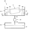
- FIG. 1 is a schematic configuration diagram showing an example of a surface treatment apparatus used in the present invention.
- the surface treatment apparatus 20 of this example includes a treatment tank 22 that contains a lubricant 21, an inclination mechanism 23 that is installed in the treatment tank 22 and supports the mold body 11 by being inclined, and a lubricant 21.
- a draining means 24 for draining from the bottom of the processing tank 22 and a receiving tank 25 for receiving the lubricating treatment agent 21 drained from the processing tank 22 are provided.
- the processing tank 22 of this example is provided with an outer tank (not shown) having a structure like an outer moat adjacent to the periphery thereof, and the outer tank receives the lubricant 21 overflowing from the processing tank 22. Be able to. Further, the outer tub and the processing tub 22 are connected by piping, and the lubricating treatment agent 21 accumulated in the outer tub can be supplied to the processing tub 22 by a circulation pump (not shown).
- the tilt mechanism 23 includes a pair of support members 23a and 23b, and shafts 26a and 26b can be attached thereto.
- the support members 23a and 23b can be individually adjusted in height, and the inclination angle of the central axis of the mold body 11 can be adjusted.
- mounting members 27a and 27b for mounting the shafts 26a and 26b on the mold body 11 are provided.
- the method of disposing the mold body 11 in the surface treatment apparatus 20 is not particularly limited.
- the shafts 26a and 26b are mounted on both ends of the mold body 11 via the mounting members 27a and 27b, and the mold body 11 is inclined. After adjusting the angle (angle formed by the central axis and the horizontal plane), the shafts 26a and 26b are attached to the support members 23a and 23b whose heights are individually adjusted in advance, and the mold body 11 is set on the tilt mechanism 23. . At this time, the lubricant 21 is not supplied to the treatment tank 22.
- the lubricant treatment agent 21 is supplied to the treatment tank 22, and the mold body 11 is immersed in the lubricant treatment agent 21.
- the lubricant 21 is supplied to the outer tank (not shown), and the lubricant 21 is supplied from the outer tank to the treatment tank 22 using a circulation pump (not shown). To do.
- the lubricant 21 is preferably supplied from the bottom of the treatment tank 22.
- the process tank 22 may be covered with a lid. By covering the lid, it is possible to prevent the surface of the mold body 11 from being scattered due to the supply of the lubricant 21, and it is possible to suppress the mold surface from being stained.
- the lubricant 21 When the lubricant 21 is continuously supplied from the outer tank to the treatment tank 22 by the circulation pump, the lubricant 21 overflows from the treatment tank 22 to the outer tank (overflow), and is supplied again from the outer tank to the treatment tank 22 by the circulation pump. Is done.
- the outer tank serves as an overflow receiving tank and a buffer tank for supplying the lubricant 21 to the processing tank 22.
- the lubricating treatment agent 21 overflows from the treatment tank 22 to the outer tank, particles derived from the respective members (the treatment tank 22 and the piping) of the surface treatment apparatus 20, the lubricating treatment agent 21, the mold body 11, and the like.
- foreign matters such as dust may be brought into the outer tank. Therefore, when supplying the lubricant 21 from the outer tank, it is preferable to filter the lubricant 21 through a filter (not shown) and then supply the lubricant 21 to the tank 22. By performing the filtration, foreign matters are removed, and a clean lubricant 21 can be supplied to the treatment tank 22. Moreover, the effect which removes the foreign material which floated on the liquid level from the processing tank 22 is also acquired by making it overflow.
- the members that come into contact with the lubricant 21 are materials that do not easily generate foreign matter, and have solvent resistance.
- a material is preferable, and specifically, metals such as SUS, aluminum, and copper, and fluorine-based resins are suitable.
- the circulating pump is preferably one that generates less particles by the sliding portion. Also, the finer the filter, the better for filtering out foreign substances.
- the filter pores preferably have a pore size of 0.45 ⁇ m or less, and more preferably have a pore size of 0.2 ⁇ m or less.
- the immersion temperature when immersing the mold body 11 in the lubricant treatment agent 21 is preferably 0 ° C. or more and 50 ° C. or less in order to suppress volatilization from the inside of the treatment tank 22.
- immersion time is not specifically limited, For example, when using the "Optool" series by Daikin Industries, Ltd. mentioned above as the lubricating treatment agent 21, 5 minutes or more are preferable.
- the method for immersing the mold body in the lubricant is not limited to the method described above.
- the height of the support members 23a and 23b is individually adjusted to adjust the inclination angle of the mold body 11. May be.
- the inclination angle may be adjusted before supplying the lubricant 21 to the treatment tank 22 or after supplying it (for example, when the mold body 11 is taken out from the lubricant 21).
- the lubricant treatment agent 21 is supplied to the treatment tank 22 after the mold body 11 is set on the tilt mechanism 23 of the surface treatment apparatus 20, but the lubricant treatment agent 21 is accommodated in the treatment tank 22. In this state, the mold body 11 may be set on the tilt mechanism 23.
- the mold body is removed from the processing agent through a first removal step, a second removal step, and a third removal step in this order.
- the first extraction step is a step of exposing a part of the mold body from the liquid surface of the lubricating treatment agent in a state where the central axis of the mold body is inclined with respect to the horizontal plane.
- the first removal step at least a part of the uppermost portion (the uppermost portion with respect to the direction of gravity) on the peripheral surface of the mold body when the central axis of the mold body is horizontal is lubricated. It is preferable to expose from the liquid surface of the agent, and it is more preferable to expose all of the uppermost portion from the liquid surface of the lubricant.
- the tilt angle of the mold body in the first take-out step that is, the angle between the center axis of the mold body and the horizontal plane is not particularly limited, but when the lubricant is an organic solvent liquid, the center axis of the mold body Is preferably inclined by 0.6 ° or more with respect to the horizontal plane. If the tilt angle is 0.6 ° or more, the liquid residue when the mold body is pulled away from the lubricant treatment liquid surface is likely to concentrate on one place on the surface of one end of the mold body. As will be described later, it is possible to effectively prevent the transfer portion 13 shown in FIG.
- the upper limit value of the tilt angle when the lubricant is an organic solvent liquid is not particularly limited, but the tilt angle is preferably smaller as the overall length of the mold body becomes longer, for example, 45 ° or less is preferable, and 10 ° or less is preferable. More preferred is 5 ° or less. If the inclination angle is 45 ° or less, the amount of the lubricant necessary for immersing the mold body while the mold body is inclined can be reduced.
- the lubricant when the lubricant is an aqueous solution, it is preferable to incline the central axis of the mold body by 2 ° or more with respect to the horizontal plane. If the inclination angle is 2 ° or more, the liquid residue when the mold main body is pulled away from the lubricant treatment liquid surface is likely to be concentrated on one surface of one end of the mold main body. It is possible to effectively prevent a stain from occurring in the transfer portion 13 shown.
- the upper limit of the tilt angle when the lubricant is an aqueous solution is not particularly limited, but the tilt angle is preferably smaller as the overall length of the mold body becomes longer, for example, 45 ° or less is preferable, and 10 ° or less is more preferable. 5 degrees or less is more preferable. If the inclination angle is 45 ° or less, the amount of the lubricant necessary for immersing the mold body while the mold body is inclined can be reduced.
- the mold is maintained while maintaining a meniscus between the exposed portion of the die body exposed from the liquid surface of the lubricant and the liquid surface of the lubricant in the first take-out step.
- the main body and the liquid surface of the lubricant are relatively moved to further expose the mold main body from the liquid surface of the processing agent.
- the lowermost part of the peripheral surface of the mold body when the central axis of the mold body is horizontal is the liquid level of the lubricant. It is preferable that the mold body is exposed from the liquid surface of the lubricating treatment agent until just before exposure.
- the “meniscus” is a concavely curved liquid surface of the lubricating treatment agent formed by the surface of the mold body and the lubricating treatment agent in contact with the surface.
- the mold body and the liquid surface of the lubricant are relatively moved while the meniscus is maintained, the lubricant is uniformly adhered to the surface of the mold body and the lubricant is removed from the mold body.
- a roll-shaped mold having a uniform surface treatment is obtained by gradually drying from a distant portion.
- a method for relatively moving the mold body and the liquid surface of the lubricant for example, a method of draining the lubricant from the processing tank while the inclined mold body is fixed, an inclined mold body
- a method of moving the slanted mold body as it is vertically upward while removing the lubricant from the treatment tank for example, a method of moving the slanted mold body as it is vertically upward while removing the lubricant from the treatment tank.
- the method of draining the lubricant from the treatment tank in a state where the inclined mold body is fixed is preferable in that the state of the meniscus can be stably maintained and the surface treatment apparatus can be simplified.
- the mold body and the liquid surface of the lubricant are relatively moved at a speed within a range where the meniscus is maintained.
- the surface treatment becomes non-uniform and occurs due to the division of the meniscus on the surface of the mold body.
- a liquid residue is generated, which aggregates and remains as a stain.
- the meniscus is divided means that visible liquid droplets or the like divided from the meniscus are generated on the surface of the transfer part of the mold body.
- the “state in which the meniscus is maintained” refers to a state in which no visible liquid droplet exists in the transfer portion of the mold body pulled up from the liquid surface of the lubricant.
- the material of the mold base material the type of the lubricant, and the like in addition to the relative movement speed between the mold body and the liquid surface of the lubricant.
- this relative moving speed is determined by the inclination angle of the mold body described later. For example, when the inclination angles are the same, the meniscus is more easily maintained as the relative movement speed becomes slower. Also, the smaller the tilt angle, the faster the relative movement speed can be while maintaining the meniscus.
- the relative movement speed is preferably 0.03 to 0.3 mm / second.
- the relative movement speed is preferably 0.001 to 0.05 mm / second.
- the inclination angle of the mold body is not particularly limited, but it is preferable to set the same inclination angle as that in the first step.
- the third removal step is a step of removing all of the mold body from the lubricant with the central axis of the mold body inclined with respect to the horizontal plane.
- the lubricant is an organic solvent liquid
- the center axis of the mold body is inclined by 0.6 ° or more with respect to the horizontal plane in the third extraction step. If the tilt angle is 0.6 ° or more, the liquid residue when the mold body is pulled away from the lubricant treatment liquid surface is likely to concentrate on one place on the surface of one end of the mold body. It is possible to effectively prevent a stain from occurring in the transfer portion 13 shown in FIG.
- the upper limit of the tilt angle when the lubricant is an organic solvent liquid is not particularly limited, but from the viewpoint of simplification of equipment when taking out and space saving, the smaller the tilt angle, the longer the overall length of the mold body. For example, preferably 45 ° or less, more preferably 10 ° or less, and further preferably 5 ° or less.
- the central axis of the mold body is inclined by 2 ° or more with respect to the horizontal plane. If the inclination angle is 2 ° or more, the liquid residue when the mold main body is pulled away from the lubricant treatment liquid surface is likely to be concentrated on one surface of one end of the mold main body. It is possible to effectively prevent a stain from occurring in the transfer portion 13 shown.
- the upper limit value of the tilt angle when the lubricant is an aqueous solution is not particularly limited, but from the viewpoint of simplification of equipment when taking out and space saving, it is preferable that the tilt angle is smaller as the overall length of the mold body becomes longer. For example, 45 ° or less is preferable, 10 ° or less is more preferable, and 5 ° or less is more preferable.
- the mold body When the mold body is removed from the lubricant through the first removal step, the second removal step, and the third removal step in order, the mold body is inclined, so that the mold body is the surface of the lubricant treatment liquid.
- the liquid residue at the time of being separated from is concentrated at one place on the surface of one end of the mold body (that is, the portion that is in contact with the lubricant until the end). Therefore, as shown in FIG. 2, the occurrence of the stain S due to the liquid residue occurs at one place on the end surface (non-transfer portion 12) of the roll-shaped mold 10, and the central surface (transfer portion 13). ) Can be prevented.
- FIG. 2 is a perspective view showing an example when the central axis of the roll-shaped mold 10 obtained by the present invention is rotated by 180 degrees.
- the central axis of the mold body it is preferable to incline the central axis of the mold body with respect to the horizontal plane. If the central axis of the mold body is inclined with respect to the horizontal plane in all the removal steps, the lubricant is applied to the uppermost part of the peripheral surface of the mold body when the central axis of the mold body is horizontal.
- the mold when the liquid remains and causes liquid dripping, the lubricant treatment liquid droplets remain in the transfer portion 12 and causes stains, and the mold body is in a state where the central axis is horizontal. It is possible to prevent the occurrence of a streak-like spot or the like at the lowermost part of the peripheral surface of the main body.
- the mold body and the lubrication are maintained while maintaining a meniscus between the surface of the mold body and the liquid surface of the lubricant. It is preferable to relatively move the liquid surface of the treatment agent. If the mold body and the liquid surface of the lubricant are moved relative to each other while maintaining the meniscus in all removal steps, the uppermost liquid residue on the peripheral surface of the mold body, the transfer section 12 and the mold It is possible to more effectively prevent the occurrence of a stain at the lowermost portion of the peripheral surface of the main body.
- the center axis of the mold body is inclined with respect to the horizontal plane, and the surface of the mold body and the lubricant liquid It is preferable to remove the mold body from the lubricant by relatively moving the mold body and the liquid surface of the lubricant with the meniscus being maintained between the surfaces.
- the mold body 11 may be inclined by, for example, a method of suspending chains having different lengths from the shafts 26a and 26b on a beam or the like.
- the timing for inclining the mold body may be when the mold body is immersed in the lubricant or before it is taken out from the lubricant. In consideration of workability, it is preferable to incline the mold body at the time of immersion in the lubricant using, for example, the surface treatment apparatus 20 shown in FIG. Further, if the mold body is tilted when immersed in the lubricant, the lubricant can be removed from the treatment tank while maintaining the meniscus, and as shown in FIG. The occurrence of spots can be easily prevented.
- the lubricating treatment agent 21 When draining the lubricating treatment agent from the treatment tank, for example, as shown in FIG. 1, the lubricating treatment agent 21 is drained from the bottom of the treatment tank 22 via the drainage means 24. The drained lubricant 21 is collected in the receiving tank 25.
- the draining method is not particularly limited as long as it can be drained while maintaining a meniscus, and may be a natural drop draining liquid or a quantitative draining liquid.
- the natural drop drainage is a method that allows drainage by providing a valve 28 at the bottom of the treatment tank 22 as shown in FIG. 1, and has a simple structure and low cost.
- the opening degree of the valve 28 is constant, the liquid drop flow rate varies depending on the liquid level of the lubricant 21. That is, since the liquid level of the lubricant 21 is high at the beginning of liquid removal, the liquid pressure is high and the liquid discharge flow rate is high (that is, the relative speed of the mold body 11 with respect to the liquid level of the lubricant 21 is high).
- the liquid discharge flow rate is small (that is, the relative speed of the mold body 11 with respect to the liquid level of the lubricant 21 is low). Even if the liquid level of the lubricant 21 is the same, the drainage flow rate can be changed depending on the opening degree of the valve 28.
- the pump is preferably one with little liquid pulsation on the pump entrance side.
- the liquid contact portion of the pump is preferably made of a material resistant to the lubricant, and examples thereof include Viton (registered trademark) and polytetrafluoroethylene.
- the surface-treated mold body can be used as a roll-shaped mold as it is, but the surface-treated mold body may be dried after the surface treatment step as necessary (drying step). When the surface-treated mold body is dried, it may be air-dried or heat-dried with a drier or the like.
- die of this invention is the state which maintained the meniscus between the surface of the metal mold
- the roll mold manufacturing method is suitable not only for manufacturing a roll mold having a short overall length but also for manufacturing a roll mold having a long total length. There is no need to deepen the treatment tank along with the entire length of the mold body as in the case of surface treatment in a vertical state.
- the method for producing an article having a fine concavo-convex structure on the surface thereof according to the present invention is formed on the surface of a roll-shaped mold obtained by the method for producing a roll-shaped mold having a fine concavo-convex structure forming step (main body production step). And a transfer step of transferring the fine concavo-convex structure comprising a plurality of pores onto the surface of the article body.
- Articles manufactured by transferring the fine concavo-convex structure (pores) of the roll-shaped mold have the reverse structure (convex part) of the fine concavo-convex structure of the roll-shaped mold transferred on the surface due to the relationship between the key and the keyhole.
- an uncured active energy ray-curable resin composition is filled between the roll mold and the transparent substrate (article body).
- the active energy ray-curable resin composition is irradiated with the active energy ray-curable resin composition in a state where the active energy ray-curable resin composition is in contact with the fine concavo-convex structure of the roll die, and then the active energy ray-curable resin composition is cured.
- a method of releasing is preferable. Thereby, an article in which a fine uneven structure made of a cured product of the active energy ray-curable resin composition is formed on the surface of the transparent substrate can be produced.
- the fine uneven structure of the obtained article is an inverted structure of the fine uneven structure of the roll mold.
- ⁇ Article body> As a transparent base material, since active energy ray irradiation is performed through the transparent base material, a material that does not significantly inhibit irradiation of active energy rays is preferable.
- the material for the transparent substrate include polyester resins (polyethylene terephthalate, polybutylene terephthalate, etc.), polymethacrylate resins, polycarbonate resins, vinyl chloride resins, ABS resins, styrene resins, and glass.
- the method of filling the active energy ray-curable resin composition includes a method of supplying the active energy ray-curable resin composition between the roll mold and the transparent substrate and then rolling and filling the active energy ray-curable resin composition. Examples thereof include a method of laminating a transparent substrate on a roll-shaped mold coated with the composition, a method of previously coating an active energy ray-curable resin composition on a transparent substrate, and laminating it on a roll-shaped mold.
- the active energy ray-curable resin composition contains a polymerization reactive compound and an active energy ray polymerization initiator.
- a non-reactive polymer or active energy ray sol-gel reactive component may be contained depending on the application, and a thickener, leveling agent, ultraviolet absorber, light stabilizer, heat stabilizer, solvent Various additives such as inorganic fillers may be included.
- polymerization reactive compound examples include monomers, oligomers, and reactive polymers having a radical polymerizable bond and / or a cationic polymerizable bond in the molecule.
- monomer having a radical polymerizable bond examples include a monofunctional monomer and a polyfunctional monomer.
- Monofunctional monomers having radical polymerizable bonds include (meth) acrylate derivatives (methyl (meth) acrylate, ethyl (meth) acrylate, propyl (meth) acrylate, n-butyl (meth) acrylate, i-butyl (meth) Acrylate, s-butyl (meth) acrylate, t-butyl (meth) acrylate, 2-ethylhexyl (meth) acrylate, lauryl (meth) acrylate, alkyl (meth) acrylate, tridecyl (meth) acrylate, stearyl (meth) acrylate, Cyclohexyl (meth) acrylate, benzyl (meth) acrylate, phenoxyethyl (meth) acrylate, isobornyl (meth) acrylate, glycidyl (meth) acrylate, tetrahydrofurfuryl (
- bifunctional monomers ethylene glycol di (meth) acrylate, tripropylene glycol di (meth) acrylate, isocyanuric acid ethylene oxide modified di (meth) acrylate, triethylene glycol di) (Meth) acrylate, diethylene glycol di (meth) acrylate, neopentyl glycol di (meth) acrylate, 1,6-hexanediol di (meth) acrylate, 1,5-pentanediol di (meth) acrylate, 1,3-butylene Glycol di (meth) acrylate, polybutylene glycol di (meth) acrylate, 2,2-bis (4- (meth) acryloxypolyethoxyphenyl) propane, 2,2-bis (4- (meth) acryloxyethoxy) Enyl) propane, 2,2-bis (4- (3- (meth) acryloxy-2-hydroxypropoxy) phenyl) propane
- Examples of the monomer having a cationic polymerizable bond include monomers having an epoxy group, an oxetanyl group, an oxazolyl group, a vinyloxy group, and the like, and a monomer having an epoxy group is particularly preferable.
- Examples of the oligomer or reactive polymer having a radical polymerizable bond and / or a cationic polymerizable bond in the molecule include unsaturated polyesters such as a condensate of unsaturated dicarboxylic acid and polyhydric alcohol; polyester (meth) acrylate, poly Ether (meth) acrylate, polyol (meth) acrylate, epoxy (meth) acrylate, urethane (meth) acrylate, cationic polymerization type epoxy compound, homopolymer or copolymer of the above-mentioned monomers having a radical polymerizable bond in the side chain, etc. Can be mentioned.
- the active energy ray polymerization initiator a known polymerization initiator can be used, and it is preferable to select appropriately according to the type of the active energy ray used when the active energy ray curable resin composition is cured.
- photoinitiators When using a photocuring reaction, photoinitiators include carbonyl compounds (benzoin, benzoin methyl ether, benzoin ethyl ether, benzoin isopropyl ether, benzoin isobutyl ether, benzyl, benzophenone, p-methoxybenzophenone, 2,2-di- Ethoxyacetophenone, ⁇ , ⁇ -dimethoxy- ⁇ -phenylacetophenone, methylphenylglyoxylate, ethylphenylglyoxylate, 4,4′-bis (dimethylamino) benzophenone, 2-hydroxy-2-methyl-1-phenylpropane -1-one, etc.), sulfur compounds (tetramethylthiuram monosulfide, tetramethylthiuram disulfide, etc.), 2,4,6-trimethylbenzoyldiphenylphosphine oxide, benzoyl Ethoxy phosphine oxide, and the
- polymerization initiators include benzophenone, 4,4-bis (diethylamino) benzophenone, 2,4,6-trimethylbenzophenone, methyl orthobenzoylbenzoate, 4-phenylbenzophenone, t-butylanthraquinone 2-ethylanthraquinone, thioxanthone (2,4-diethylthioxanthone, isopropylthioxanthone, 2,4-dichlorothioxanthone, etc.), acetophenone (diethoxyacetophenone, 2-hydroxy-2-methyl-1-phenylpropan-1-one, Benzyldimethyl ketal, 1-hydroxycyclohexyl-phenylketone, 2-methyl-2-morpholino (4-thiomethylphenyl) propan-1-one, 2-benzyl-2-dimethylamino-1- ( -Morpholinophenyl) -butanone), benzophenone, 4,4-bis
- the content of the active energy ray polymerization initiator in the active energy ray curable resin composition is preferably 0.1 to 10 parts by mass with respect to 100 parts by mass of the polymerization reactive compound.
- the active energy ray polymerization initiator is less than 0.1 part by mass, the polymerization is difficult to proceed.
- the active energy ray polymerization initiator exceeds 10 parts by mass, the cured resin may be colored or the mechanical strength may be lowered.
- Non-reactive polymers include acrylic resins, styrene resins, polyurethane resins, cellulose resins, polyvinyl butyral resins, polyester resins, thermoplastic elastomers, and the like.
- Examples of the active energy ray sol-gel reactive component include alkoxysilane compounds and alkyl silicate compounds.
- alkoxysilane compound examples include those represented by R 3 x Si (OR 4 ) y .
- tetramethoxysilane tetra-iso-propoxysilane, tetra-n-propoxysilane, tetra-n-butoxysilane, tetra-sec-butoxysilane, tetra-tert-butoxysilane, methyltriethoxysilane, methyl
- tripropoxysilane methyltributoxysilane, dimethyldimethoxysilane, dimethyldiethoxysilane, trimethylethoxysilane, trimethylmethoxysilane, trimethylpropoxysilane, and trimethylbutoxysilane.
- alkyl silicate compound examples include those represented by R 5 O [Si (OR 7 ) (OR 8 ) O] z R 6 .
- R 5 to R 8 each represents an alkyl group having 1 to 5 carbon atoms, and z represents an integer of 3 to 20.
- Specific examples include methyl silicate, ethyl silicate, isopropyl silicate, n-propyl silicate, n-butyl silicate, n-pentyl silicate, acetyl silicate and the like.
- An article having a fine concavo-convex structure on its surface is manufactured as follows using, for example, a manufacturing apparatus 30 shown in FIG. Active energy rays from the tank 31 between a roll-shaped mold 10 having a fine uneven structure (not shown) on the surface and a strip-shaped film 41 (transparent substrate) moving along the surface of the roll-shaped mold 10 A curable resin composition 32 is supplied.
- the film 41 and the active energy ray-curable resin composition 32 are nipped between the roll-shaped mold 10 and the nip roll 34 whose nip pressure is adjusted by the pneumatic cylinder 33, and the active energy ray-curable resin composition 32 is
- the film 41 and the roll mold 10 are uniformly distributed, and at the same time, the recesses of the fine uneven structure of the roll mold 10 are filled.
- the active energy ray curable resin composition 32 is irradiated to the active energy ray curable resin composition 32 through the film 41 from the active energy ray irradiation device 35 installed below the roll-shaped mold 10 to cure the active energy ray curable resin composition 32.
- the cured resin layer 42 to which the fine concavo-convex structure on the surface of the roll mold 10 is transferred is formed.
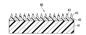
- an article 40 as shown in FIG. 4 is obtained.
- Examples of the active energy ray irradiation device 35 include a high-pressure mercury lamp and a metal halide lamp.
- the irradiation amount of the active energy ray may be an energy amount that allows the active energy ray-curable resin composition to cure, and is usually about 100 to 10,000 mJ / cm 2 .
- ⁇ Article> 4 has a cured resin layer 42 formed on the surface of a film 41 (transparent substrate).
- the cured resin layer 42 is a film made of a cured product of the active energy ray curable resin composition, and has a fine uneven structure on the surface.
- the fine concavo-convex structure on the surface of the article 40 is formed by, for example, transferring the fine concavo-convex structure on the surface of the oxide film, and has a plurality of convex portions 43 made of a cured product of the active energy ray-curable resin composition. .
- the fine concavo-convex structure is preferably a so-called moth-eye structure in which a plurality of protrusions (convex portions) having a substantially conical shape or a pyramid shape are arranged. It is known that the moth-eye structure in which the distance between the protrusions is less than or equal to the wavelength of visible light is an effective anti-reflection measure by continuously increasing the refractive index from the refractive index of air to the refractive index of the material. It has been.
- the articles produced according to the present invention exhibit various performances such as antireflection performance and water repellency performance due to the fine concavo-convex structure on the surface.
- an article having a fine concavo-convex structure is a sheet or film
- the surface of an object such as an image display device (TV, mobile phone display, etc.), display panel, meter panel, etc.
- TV mobile phone display, etc.
- display panel meter panel
- it can be used by pasting it on or insert molding it.
- water repellency it is also used as a member for objects that may be exposed to rain, water, steam, etc., such as bathroom windows and mirrors, solar cell members, automobile mirrors, signboards, glasses lenses, etc. be able to.
- an antireflection article is manufactured using a transparent substrate having a shape suitable for the application, and this is used as a member constituting the surface of the object. You can also.
- an article having a fine uneven structure on the surface may be attached to the front plate, or the front plate itself may be It can also consist of an article having a structure on its surface.
- an article having a fine concavo-convex structure on the surface of a rod lens array attached to a sensor array for reading an image, a cover glass of an image sensor such as a FAX, a copying machine or a scanner, or a contact glass for placing an original of a copying machine May be used.
- an article having a fine concavo-convex structure on the surface of a light receiving portion of an optical communication device such as visible light communication
- signal reception sensitivity can be improved.
- articles having a fine concavo-convex structure on the surface can be developed for optical uses such as optical waveguides, relief holograms, optical lenses, and polarization separation elements, and for use as cell culture sheets.
- the method for producing an article having a fine concavo-convex structure on the surface according to the present invention described above is a roll-shaped mold having a fine concavo-convex structure forming step (main body producing step) in the method for producing a roll-shaped mold according to the present invention. Since the roll-shaped mold obtained by the manufacturing method is used, the stain pattern is not transferred, and a high-quality article can be obtained. Moreover, since the surface of the roll-shaped mold is surface-treated with a lubricant, the mold release property is excellent. Therefore, an article having a fine uneven structure on the surface can be manufactured with high productivity.
- a roll mold was produced as follows.
- a roll-shaped aluminum substrate (purity: 99.99%, diameter 200 mm, total length: 320 mm) was prepared as a mold substrate.
- (Main body production process) (A) Process: This aluminum substrate was anodized in a 0.3 M oxalic acid aqueous solution for 30 minutes under conditions of a direct current of 40 V and a temperature of 16 ° C. (B) Process: The aluminum plate on which the oxide film was formed was immersed in a 6% by mass phosphoric acid / 1.8% by mass chromic acid mixed aqueous solution for 6 hours to remove the oxide film. (C) Process: This aluminum substrate was anodized in a 0.3 M oxalic acid aqueous solution for 30 seconds under conditions of a direct current of 40 V and a temperature of 16 ° C.
- the mold main body obtained in the main body manufacturing process was washed with pure water so that no stains or foreign substances adhered to the surface.
- the mold body was surface-treated as follows using the surface treatment apparatus 20 shown in FIG.
- the lubricant 21 a fluororesin-based lubricant obtained by diluting “OPTOOL DSX” manufactured by Daikin Industries, Ltd. 200 times with a diluent “OPTOOL HD-ZV” manufactured by Daikin Industries, Ltd. was used.
- the processing tank 22 what was equipped with the outer tank (not shown) adjacent to the circumference
- the shafts 26a and 26b are mounted on both ends of the mold body 11 via the mounting members 27a and 27b so that the inclination angle of the mold body 11 is 5 ° (that is, the central axis of the mold body 11 is After adjustment (inclined by 5 ° from the horizontal state), the shafts 26a and 26b were attached to the support members 23a and 23b whose heights were individually adjusted in advance, and the mold body 11 was set on the tilt mechanism 23. At this time, the lubricant 21 is not supplied to the treatment tank 22. Next, a lubricant adjusting agent 21 whose liquid temperature is adjusted to 20 ° C.
- Lubricant 21 was supplied from the bottom of the treatment tank 22 using a magnet pump “MD-55R-M” manufactured by the company, and the mold body 11 was immersed in the lubricant 21 for 10 minutes (immersion step).
- the lubricant 21 was filtered through a filter (a PES membrane cartridge filter “TCS-E020-S1FE” manufactured by Advantech) and then supplied to the tank 22. .
- the lubricant 21 was overflowed from the processing tank 22 to the outer tank, and foreign matters floating on the liquid surface of the processing tank 22 were removed.
- the lubricating treatment agent 21 overflowed to the outer tank was filtered through a filter and supplied again to the treatment tank 22, and the lubricating treatment agent 21 was circulated between the outer tank and the treatment tank 22.
- the circulation of the lubricating treatment agent 21 is stopped, the valve 28 provided at the bottom of the treatment tank 22 is opened, and the lubricating treatment agent 21 is drained from the draining means 24 by a natural drop draining solution. Then, the mold body 11 was removed from the lubricant 21 (first to third extraction steps), and the mold body 11 was surface-treated. At this time, the opening degree of the valve 28 was adjusted so that the average value of the relative movement speed between the mold body 11 and the liquid surface of the lubricant 21 in the 30 seconds after the start of liquid removal was 0.067 mm / second.
- This relative movement speed is a speed at which the mold body 11 can be taken out of the lubricant 21 while maintaining a meniscus between the surface of the mold body 11 and the liquid surface of the lubricant 21.
- the valve 28 a needle valve was used.
- SUS flexible piping was used as the drainage means 24 as the drainage means 24 .
- Example 1-2 Except that the inclination angle of the mold body 11 was changed to 3 °, a roll mold was manufactured in the same manner as in Example 1-1, and the occurrence of spots was evaluated. The results are shown in Table 1.
- Example 1-3 Except that the inclination angle of the mold body 11 was changed to 1 °, a roll-shaped mold was manufactured in the same manner as in Example 1-1, and the occurrence of spots was evaluated. The results are shown in Table 1.
- Example 1-3 A roll-shaped mold was manufactured in the same manner as in Example 1-1 except that the inclination angle of the mold body 11 was changed to 1 ° and the average value of the relative movement speed was changed to 10 mm / second. Evaluation was performed. The results are shown in Table 1.
- the relative movement speed is a speed at which the mold body 11 is taken out from the lubricant 21 in a state where the meniscus is not maintained between the surface of the mold body 11 and the liquid surface of the lubricant 21.
- a phosphoric acid ester compound (manufactured by Nikko Chemical Co., “TDP8”) is dissolved in pure water, and the phosphoric acid ester compound has a concentration of 0.1% by mass (phosphoric acid ester-based lubricant ) was used. Further, the inclination angle of the mold body 11 was changed to 1 °, and the average value of the relative movement speed was changed to 0.0046 mm / second. Otherwise, a roll mold was produced in the same manner as in Example 1-1, and the occurrence of spots was evaluated. The results are shown in Table 2.
- a phosphoric acid ester compound (manufactured by Nikko Chemical Co., “TDP8”) is dissolved in pure water, and the phosphoric acid ester compound has a concentration of 0.1% by mass (phosphoric acid ester-based lubricant ) was used.
- the inclination angle of the mold body 11 was changed to 2 °. Otherwise, a roll mold was produced in the same manner as in Example 1-1, and the occurrence of spots was evaluated.
- the results are shown in Table 2.
- the relative movement speed is a speed at which the mold body 11 is taken out from the lubricant 21 in a state where the meniscus is not maintained between the surface of the mold body 11 and the liquid surface of the lubricant 21.
- Comparative Example 2-1 In the case of Comparative Example 2-1, in which an aqueous solution (phosphate ester-based lubricant) is used as the lubricant and the mold body is tilted at an angle of 1 ° and taken out from the lubricant, the transfer portion is stained. Occurred.
- Comparative Example 1-3 and Comparative Example 2-3 In the case of Comparative Example 1-3 and Comparative Example 2-3 in which the mold body was removed from the lubricant without maintaining the meniscus between the surface of the mold body and the liquid level of the lubricant, In the mold body, an amount of liquid that could confirm the dripping of the lubricant remained from the entire surface of the mold body. In the roll molds obtained in Comparative Examples 1-3 and 2-3, irregular spots due to residual liquid droplets generated by the division of the meniscus occurred on the entire mold surface.
- the roll-shaped mold obtained by the roll-shaped mold manufacturing method of the present invention is useful as a mold for manufacturing an article having a fine concavo-convex structure on the surface by a roll-to-roll imprint method.
Landscapes
- Engineering & Computer Science (AREA)
- Mechanical Engineering (AREA)
- Moulds For Moulding Plastics Or The Like (AREA)
- Shaping Of Tube Ends By Bending Or Straightening (AREA)
- Exposure Of Semiconductors, Excluding Electron Or Ion Beam Exposure (AREA)
Abstract
Description
本願は、2011年06月22日に、日本に出願された特願2011-138300号、に基づき優先権を主張し、その内容をここに援用する。
離型性を向上させるための金型の表面処理方法として、例えば金型をフッ素樹脂系潤滑処理剤に浸漬させ、金型表面にフッ素系樹脂の被覆層を設ける金型の表面処理方法が知られている(例えば特許文献1参照)。特許文献1によれば、被加工物である金型を上下動させることによって、フッ素樹脂系潤滑処理剤を収容した処理槽内に金型を浸漬および取り出して、金型を表面処理している。
また、短時間でロール状金型を取り出すと、表面処理が不均一となり、被覆斑が生じやすかった。
しかし、ロール状金型がフッ素樹脂系潤滑処理剤の液面から引き離される際に、フッ素樹脂系潤滑処理剤の液滴が、水平状態のロール状金型表面の最下部(重力方向を基準としたときの最下部)全体に残ってしまう。液滴が残った箇所はフッ素樹脂が他の部位に比べ厚塗りの状態になり、図5に示すように、ロール状金型50の表面に1本筋のシミSが発生するといった問題点があった。なお、図5は、表面処理後のロール状金型50の中心軸を180度回転させたときの斜視図である。
シミ発生のメカニズムは以下の通りである。フッ素樹脂を溶解する希釈剤は揮発性であるが、フッ素樹脂自身は揮発しないため、水平状態のロール状金型表面の最下部に表面張力で残存している希釈剤が揮発した際、希釈剤中のフッ素樹脂が凝集して最下部全体にシミとして残る。
図5に示すように、ロール状金型50の表面に1本筋のシミSが発生すると、転写部53にもシミが存在することになるため、このシミSの模様が成形品に転写されてしまい、製品の欠陥となる。特にナノメートルオーダーの凹凸構造を転写するロール状金型の場合には、上記の問題が顕著となる。
しかし、上述したように、金型の端部の表面(非転写部)は転写に使用されないので、端部の縁部にリング状にシミが発生しても、このシミの模様が成形品に転写される恐れはない。
(1) ロール状の金型本体の表面が処理剤で処理されたロール状金型を製造する方法であって、前記金型本体を前記処理剤に浸漬させる浸漬工程と、前記金型本体の中心軸を水平面に対して傾斜させた状態で、前記金型本体の一部を前記処理剤の液面から露出させる第1の取り出し工程と、前記金型本体の露出した部分と前記処理剤の液面との間にメニスカスを維持した状態で、前記金型本体と前記処理剤の液面とを相対的に移動させ、前記金型本体を前記処理剤の液面からさらに露出させる第2の取り出し工程と、前記金型本体の中心軸を水平面に対して傾斜させた状態で、前記金型本体の全てを前記処理剤から取り出す第3の取り出し工程とを有し、前記処理剤が有機溶剤液であり、前記第3の取り出し工程において、前記金型本体の中心軸を水平面に対して0.6°以上傾斜させる、ロール状金型の製造方法。
(4) 前記浸漬工程の前に、前記金型本体の表面に微細凹凸構造を形成する微細凹凸構造形成工程をさらに有する、(1)~(3)のいずれか一項に記載のロール状金型の製造方法。
(5) 前記微細凹凸構造は、陽極酸化処理により形成される、(4)に記載のロール状金型の製造方法。
(6) (4)または(5)に記載のロール状金型の製造方法により得られた、ロール状金型の表面の微細凹凸構造を物品本体の表面に転写する転写工程を有する、微細凹凸構造を表面に有する物品の製造方法。
なお、本発明において、「(メタ)アクリレート」は「アクリレートおよび/またはメタクリレート」を、「(メタ)アクリロイル基」は「メタクリロイル基および/またはアクリロイル基」をそれぞれ意味する。
また、「活性エネルギー線」とは、電子線、紫外線、可視光線、プラズマ、赤外線などの熱線等を意味する。
本発明のロール状金型の製造方法は、ロール状の金型本体の表面が処理剤で処理されたロール状金型を製造する方法である。
本発明のロール状金型の製造方法は、浸漬工程と、第1の取り出し工程と、第2の取り出し工程と、第3の取り出し工程とを有する。
前記ロール状金型の製造方法は、浸漬工程の前に、金型本体の表面に微細凹凸構造を形成する微細凹凸構造形成工程(本体作製工程)をさらに有していてもよい。
以下、各工程について説明する。なお、本明細書において、浸漬工程と、第1の取り出し工程と、第2の取り出し工程と、第3の取り出し工程とを総称して「表面処理工程」という。
微細凹凸構造形成工程(本体作製工程)は、金型基材の表面に微細凹凸構造が形成されたロール状の金型本体を作製する工程である。
金型基材の材質としては、純アルミニウム、アルミニウム合金等、一般に金型として用いることができる材質が挙げられる。金型基材の形状は、ロール状である。
(a)ロール状のアルミニウム基材を電解液中、定電圧下で陽極酸化して酸化皮膜を形成する工程。
(b)酸化皮膜の少なくとも一部を除去し、陽極酸化の細孔発生点を形成する工程。
(c)ロール状のアルミニウム基材を電解液中、再度陽極酸化し、細孔発生点に細孔を有する酸化皮膜を形成する工程。
(d)細孔の径を拡大させる工程。
(e)前記(c)工程と(d)工程を繰り返し行う工程。
(a)工程では、ロール状のアルミニウム基材を電解液中、定電圧下で陽極酸化して酸化皮膜を形成する。アルミニウム基材を陽極酸化すると、細孔を有する酸化皮膜が形成される。
アルミニウム基材の純度は、99%以上が好ましく、99.5%以上がより好ましく、99.8%以上が特に好ましい。アルミニウム基材の純度が低いと、陽極酸化した時に、不純物の偏析により可視光を散乱する大きさの凹凸構造が形成されたり、陽極酸化で得られる細孔の規則性が低下したりすることがある。
電解液としては、硫酸、シュウ酸、リン酸等が挙げられる。
シュウ酸の濃度は、0.7M以下が好ましい。シュウ酸の濃度が0.7Mを超えると、電流値が高くなりすぎて酸化皮膜の表面が粗くなることがある。
化成電圧が30~60Vの時、周期が100nmの規則性の高い細孔を有する陽極酸化アルミナを得ることができる。化成電圧がこの範囲より高くても低くても規則性が低下する傾向にある。
電解液の温度は、60℃以下が好ましく、45℃以下がより好ましい。電解液の温度が60℃を超えると、いわゆる「ヤケ」といわれる現象がおこり、細孔が壊れたり、表面が溶けて細孔の規則性が乱れたりすることがある。
硫酸の濃度は0.7M以下が好ましい。硫酸の濃度が0.7Mを超えると、電流値が高くなりすぎて定電圧を維持できなくなることがある。
化成電圧が25~30Vの時、周期が63nmの規則性の高い細孔を有する陽極酸化アルミナを得ることができる。化成電圧がこの範囲より高くても低くても規則性が低下する傾向がある。
電解液の温度は、30℃以下が好ましく、20℃以下がよりに好ましい。電解液の温度が30℃を超えると、いわゆる「ヤケ」といわれる現象がおこり、細孔が壊れたり、表面が溶けて細孔の規則性が乱れたりすることがある。
(b)工程では、(a)工程で形成された酸化皮膜の少なくとも一部を除去し、陽極酸化の細孔発生点を形成する。陽極酸化の細孔発生点を形成することで細孔の規則性を向上することができる。
酸化皮膜を除去する方法としては、アルミニウムを溶解せず、酸化皮膜を選択的に溶解する溶液に溶解させて除去する方法が挙げられる。このような溶液としては、例えばクロム酸/リン酸混合液等が挙げられる。
(c)工程では、酸化皮膜の少なくとも一部を除去したアルミニウム基材を電解液中、再度陽極酸化し、細孔発生点に円柱状の細孔を有する酸化皮膜を形成する。
陽極酸化は、(a)工程と同様な条件で行えばよい。陽極酸化の時間を長くするほど深い細孔を得ることができる。
(d)工程では、(c)工程で形成された酸化皮膜の細孔の径を拡大させる処理(以下、「細孔径拡大処理」という。)を行う。細孔径拡大処理は、酸化皮膜を溶解する溶液に浸漬して陽極酸化で得られた細孔の径を拡大させる処理である。このような溶液としては、例えば5質量%程度のリン酸水溶液等が挙げられる。
細孔径拡大処理の時間を長くするほど、細孔径は大きくなる。
(e)工程では、(c)工程の陽極酸化と、(d)工程の細孔径拡大処理を繰り返す。すると、直径が開口部から深さ方向に連続的に減少する形状の細孔を有する陽極酸化アルミナが形成され、アルミニウム基材の表面に陽極酸化アルミナを有するロール状の金型本体が得られる。
繰り返し回数は、合計で3回以上が好ましく、5回以上がより好ましい。繰り返し回数が2回以下では、非連続的に細孔の直径が減少するため、このような細孔を有する陽極酸化アルミナを用いて製造された微細凹凸構造の反射率低減効果は不十分となる場合がある。
また、凹部の平均深さは、80~500nmが好ましく、120~400nmがより好ましく、150~300nmが特に好ましい。
表面処理工程は、金型本体の表面を処理剤で処理する工程である。浸漬工程の前に微細凹凸構造形成工程(本体作製工程)を行う場合、表面処理工程は該本体作製工程で得られた金型本体の微細凹凸構造が形成された表面を処理剤で処理する工程である。
金型本体を表面処理することで、ロール状金型の微細凹凸構造を転写する際に、転写に用いる樹脂材料が微細凹凸構造の凹部に詰まるのを抑制できる。特に、表面にナノメートルオーダーの微細な凹凸構造が形成されたロール状金型を転写に用いる場合には、一旦、樹脂材料が凹部に詰まると除去しにくくなるので、金型本体を表面処理しておく。
本発明に係る方法においては、金型本体を処理剤に浸漬させた後、該処理剤から金型本体を取り出して、金型本体の表面を処理剤で処理する。浸漬工程の前に微細凹凸構造形成工程(本体作製工程)を行う場合は、本体作製工程で得られた金型本体を処理剤に浸漬させた後、該処理剤から金型本体を取り出して、金型本体の微細凹凸構造が形成された表面を潤滑処理剤で処理する。
なお、金型本体を表面処理する前に、表面状態を清浄な状態にしておくことが好ましく、特にシミ、異物等の付着がある場合は、これらを除去しておくのが好ましい。
以下、表面処理工程について詳細に説明する。
処理剤としては、例えば潤滑処理剤が挙げられ、具体的にはフッ素系樹脂やリン酸エステル化合物などが挙げられる。
処理剤としては、フッ素系樹脂が有機溶剤からなる希釈剤に溶解したフッ素樹脂系潤滑処理剤等の有機溶剤液、リン酸エステル化合物が水に溶解したリン酸エステル系潤滑処理剤等の水溶液などを用いるのが好ましい。
ここで、官能基(A)とは、金型本体の表面に存在する官能基のことであり、フッ素樹脂系潤滑処理剤が有している反応性の官能基(B)と反応して、化学結合を形成し得る基を意味する。
官能基(A)としては、水酸基、アミノ基、カルボキシル基、メルカプト基、エポキシ基、エステル基等が挙げられ、フッ素樹脂系潤滑処理剤が反応性の官能基(B)として有することが多い加水分解性シリル基との反応性がよい点から、水酸基が特に好ましい。
方法(1):金型本体の微細凹凸構造が形成された側の表面をプラズマ処理することによって、該表面に官能基(A)を導入する方法。
方法(2):金型本体の微細凹凸構造が形成された側の表面を、官能基(A)またはその前駆体を有する化合物(シランカップリング剤等)で処理することによって、該表面に官能基(A)を導入する方法。
官能基(A)が水酸基の場合、官能基(B)としては、加水分解性シリル基、シラノール基、チタン原子もしくはアルミニウム原子を含む加水分解性基等が挙げられ、水酸基との反応性がよい点から、加水分解性シリル基またはシラノール基が好ましい。加水分解性シリル基とは、加水分解によってシラノール基(Si-OH)を生成する基であり、Si-OR1(R1はアルキル基である。)、Si-X(Xはハロゲン原子である。)等が挙げられる。
加水分解性シリル基を有するフッ素化合物の市販品としては、例えば、フルオロアルキルシラン、信越化学工業社製の「KBM-7803」、ダイキン工業社製の「オプツール」シリーズ(例えば「オプツールDSX」など)、住友スリーエム社製の「ノベックEGC-1720」などが挙げられる。なお、「オプツール」シリーズを用いる場合は、「オプツールDSX」単体で使用したり、「オプツールDSX」を希釈剤(例えばダイキン工業社製の「オプツールHD-ZV」)にて希釈させて使用したりする。

R2はの炭素数は3~18のアルキル基が好ましい。
mはエチレンオキサイドの平均付加モル数を示し、1~10が好ましい。
浸漬工程は、金型本体を処理剤に浸漬させる工程である。
金型本体を処理剤へ浸漬させる方法の一例について、図1を参照しながら以下に示すが、本発明は以下の方法に限定されない。
なお、以下に説明する浸漬工程および第1~第3の取り出し工程は、処理剤として潤滑処理剤を用いた場合の例である。
シャフト26a,26bの一端には、金型本体11にシャフト26a,26bを装着させるための装着部材27a,27bが設けられている。
潤滑処理剤21の供給は、まず外槽(図示略)へ潤滑処理剤21を供給し、外槽から処理槽22へ循環ポンプ(図示略)を用いて潤滑処理剤21を処理槽22へ供給する。潤滑処理剤21は、処理槽22の底部から供給されるのが好ましい。
また、外槽から潤滑処理剤21を供給する際は、処理槽22に蓋を被せてもよい。蓋を被せることにより、潤滑処理剤21の供給に伴う、金型本体11の表面への飛び散りを防ぐことができ、これに起因する金型表面のシミを抑制することができる。
従って、外槽から潤滑処理剤21を供給する際は、フィルター(図示略)を通して潤滑処理剤21を濾過してから、処理槽22へ供給するのが好ましい。濾過を行うことで、異物が除去され、清浄な潤滑処理剤21を処理槽22へ供給することができる。
また、オーバーフローさせることでも液面に浮いた異物を処理槽22から除去する効果が得られる。特に、液面に浮遊する異物は、表面処理工程の後に金型を乾燥させる際に金型表面に付着することが多く、特にナノメートルオーダーの凹凸構造を転写する金型の場合には金型表面の異物は顕著な問題となる。
また、同じ理由で、循環ポンプは摺動部によるパーティクル発生が少ないものが好ましい。
また、フィルターは異物を濾過させるために、目の細かいものほど好ましい。フィルター孔は、好ましくは孔径0.45μm以下であり、より好ましくは孔径0.2μm以下である。
また、浸漬時間は特に限定されないが、例えば潤滑処理剤21として前述したダイキン工業社製の「オプツール」シリーズを用いる場合は、5分以上が好ましい。
また、上述した方法では、表面処理装置20の傾斜機構23に金型本体11をセットした後で潤滑処理剤21を処理槽22に供給しているが、処理槽22に潤滑処理剤21が収容された状態で、傾斜機構23に金型本体11をセットしてもよい。
処理剤からの金型本体の取り出しは、第1の取り出し工程、第2の取り出し工程、第3の取り出し工程を順に経て行われる。
第1の取り出し工程では、金型本体の中心軸が水平となった状態のときの金型本体の周面における最上部(重力方向を基準とした場合の最上部)の少なくとも一部を潤滑処理剤の液面から露出させることが好ましく、最上部の全てを潤滑処理剤の液面から露出させることがより好ましい。
潤滑処理剤が有機溶剤液である場合の傾斜角度の上限値については特に制限されないが、金型本体の全長が長くなるほど傾斜角度は小さい方が好ましく、例えば45°以下が好ましく、10°以下がより好ましく、5°以下がさらに好ましい。傾斜角度が45°以下であれば、金型本体を傾斜させた状態で金型本体を浸漬させるために必要な潤滑処理剤の液量を低減することができる。
潤滑処理剤が水溶液である場合の傾斜角度の上限値については特に制限されないが、金型本体の全長が長くなるほど傾斜角度は小さい方が好ましく、例えば45°以下が好ましく、10°以下がより好ましく、5°以下がさらに好ましい。傾斜角度が45°以下であれば、金型本体を傾斜させた状態で金型本体を浸漬させるために必要な潤滑処理剤の液量を低減することができる。
第2の取り出し工程では、金型本体の中心軸が水平となった状態のときの金型本体の周面における最下部(重力方向を基準とした場合の最下部)が潤滑処理剤の液面から露出する直前まで、金型本体を潤滑処理剤の液面から露出させることが好ましい。
メニスカスが維持された状態で金型本体と潤滑処理剤の液面とを相対的に移動させると、潤滑処理剤が金型本体の表面に均一に付着しつつ、潤滑処理剤が金型本体から離れた部分から徐々に乾燥していき、均一に表面処理されたロール状金型が得られる。
ここで、「メニスカスが分断される」とは、金型本体の表面にメニスカスから分断した、視認可能な液滴等が金型本体の転写部表面に発生することである。一方、「メニスカスが維持された状態」とは、潤滑処理剤の液面から引き上げられた金型本体の転写部に、視認されるような液滴が存在しない状態のことを指す。
潤滑処理剤としてリン酸エステル系潤滑処理剤等の水溶液を用いる場合、相対移動速度は0.001~0.05mm/秒が好ましい。
潤滑処理剤が有機溶剤液である場合、第3の取り出し工程では金型本体の中心軸を水平面に対して0.6°以上傾斜させる。傾斜角度が0.6°以上であれば、金型本体が潤滑処理剤液面から引き離される際の液残りが、金型本体の一方の端部の表面の一箇所に集中しやすくなり、図2に示す転写部13にシミが発生するのを効果的に防止できる。
潤滑処理剤が有機溶剤液である場合の傾斜角度の上限値については特に制限されないが、取り出す際の設備の簡素化や省スペースの観点から、金型本体の全長が長くなるほど傾斜角度は小さい方が好ましく、例えば45°以下が好ましく、10°以下がより好ましく、5°以下がさらに好ましい。
潤滑処理剤が水溶液である場合の傾斜角度の上限値については特に制限されないが、取り出す際の設備の簡素化や省スペースの観点から、金型本体の全長が長くなるほど傾斜角度は小さい方が好ましく、例えば45°以下が好ましく、10°以下がより好ましく、5°以下がさらに好ましい。
なお、図2は、本発明により得られたロール状金型10の中心軸を180度回転させたときの一例を示す斜視図である。
また、第1の取り出し工程、第2の取り出し工程、および第3の取り出し工程では、金型本体の表面と潤滑処理剤の液面との間にメニスカスを維持した状態で、金型本体と潤滑処理剤の液面とを相対的に移動させることが好ましい。全ての取り出し工程においてメニスカスを維持した状態で金型本体と潤滑処理剤の液面とを相対的に移動させれば、金型本体の周面における最上部の液残り、転写部12や金型本体の周面における最下部におけるシミの発生をより効果的に防止することができる。
よって、表面処理工程では、金型本体を潤滑処理剤に浸漬させた後、金型本体の中心軸を水平面に対して傾斜させた状態で、かつ、金型本体の表面と潤滑処理剤の液面との間にメニスカスを維持した状態で、金型本体と潤滑処理剤の液面とを相対的に移動させて、潤滑処理剤から金型本体を取り出すことが好ましい。
抜液方法は、メニスカスを維持した状態で抜液できるものであれば特に限定されず、自然落差抜液でもよいし、定量抜液でもよい。
表面処理された金型本体は、そのままロール状金型として用いることができるが、必要に応じて表面処理工程の後に、表面処理された金型本体を乾燥させてもよい(乾燥工程)。
表面処理された金型本体を乾燥させる場合は、風乾でもよいし、乾燥機等による加熱乾燥でもよい。
以上説明した本発明のロール状金型の製造方法は、表面処理工程のうち、少なくとも第1の取り出し工程および第3の取り出し工程において、金型本体の中心軸を水平面に対して傾斜させた状態で、潤滑処理剤から金型本体を取り出す。従って、金型本体の中心軸を鉛直にして表面処理する場合に比べて短時間で金型本体を潤滑処理剤から取り出すことができ、短時間での表面処理が可能となる。
また、本発明のロール状金型の製造方法は、表面処理工程のうち、少なくとも第2の取り出し工程において、金型本体の表面と潤滑処理剤の液面との間にメニスカスを維持した状態で、金型本体と潤滑処理剤の液面とを相対的に移動させて、潤滑処理剤から金型本体を取り出す。従って、ロール状金型表面の転写部でのシミの発生を抑制しつつ、均一に表面処理できる。よって、ロール状金型の微細凹凸構造を成形品に転写しても、シミの模様は転写されない。
前記ロール状金型の製造方法は、全長が短いロール状金型を製造する場合はもちろんのこと、全長が長いロール状金型を製造する場合にも好適であり、金型本体の中心軸を鉛直にして表面処理する場合のように処理槽を金型本体の全長に併せて深くする必要がない。
本発明の、微細凹凸構造を表面に有する物品の製造方法は、微細凹凸構造形成工程(本体作製工程)を有するロール状金型の製造方法で得られた、ロール状金型の表面に形成された複数の細孔からなる微細凹凸構造を、物品本体の表面に転写する転写工程を有する。
ロール状金型の微細凹凸構造(細孔)を転写して製造された物品は、その表面にロール状金型の微細凹凸構造の反転構造(凸部)が、鍵と鍵穴の関係で転写される。
透明基材としては、活性エネルギー線の照射を、該透明基材を介して行うため、活性エネルギー線の照射を著しく阻害しないものが好ましい。透明基材の材料としては、例えばポリエステル樹脂(ポリエチレンテレフタレート、ポリブチレンテレフタレート等)、ポリメタクリレート樹脂、ポリカーボネート樹脂、塩化ビニル樹脂、ABS樹脂、スチレン樹脂、ガラス等が挙げられる。
活性エネルギー線硬化性樹脂組成物を用いる方法は、熱硬化性樹脂組成物を用いる方法に比べて加熱や硬化後の冷却を必要としないため、短時間で微細凹凸構造を転写することができ、量産に好適である。
活性エネルギー線硬化性樹脂組成物の充填方法としては、ロール状金型と透明基材の間に活性エネルギー線硬化性樹脂組成物を供給した後に圧延して充填する方法、活性エネルギー線硬化性樹脂組成物を塗布したロール状金型上に透明基材をラミネートする方法、あらかじめ透明基材上に活性エネルギー線硬化性樹脂組成物を塗布してロール状金型にラミネートする方法等が挙げられる。
ラジカル重合性結合を有するモノマーとしては、単官能モノマー、多官能モノマーが挙げられる。
分子中にラジカル重合性結合および/またはカチオン重合性結合を有するオリゴマーまたは反応性ポリマーとしては、不飽和ジカルボン酸と多価アルコールとの縮合物等の不飽和ポリエステル類;ポリエステル(メタ)アクリレート、ポリエーテル(メタ)アクリレート、ポリオール(メタ)アクリレート、エポキシ(メタ)アクリレート、ウレタン(メタ)アクリレート、カチオン重合型エポキシ化合物、側鎖にラジカル重合性結合を有する上述のモノマーの単独または共重合ポリマー等が挙げられる。
活性エネルギー線ゾルゲル反応性成分としては、例えば、アルコキシシラン化合物、アルキルシリケート化合物等が挙げられる。
微細凹凸構造を表面に有する物品は、例えば、図3に示す製造装置30を用いて、下記のようにして製造される。
表面に微細凹凸構造(図示略)を有するロール状金型10と、ロール状金型10の表面に沿って移動する帯状のフィルム41(透明基材)との間に、タンク31から活性エネルギー線硬化性樹脂組成物32を供給する。
剥離ロール36により、表面に硬化樹脂層42が形成されたフィルム41をロール状金型10から剥離することによって、図4に示すような物品40を得る。
活性エネルギー線の照射量は、活性エネルギー線硬化性樹脂組成物の硬化が進行するエネルギー量であればよく、通常、100~10000mJ/cm2程度である。
図4に示す物品40は、フィルム41(透明基材)の表面に硬化樹脂層42が形成されたものである。
硬化樹脂層42は、活性エネルギー線硬化性樹脂組成物の硬化物からなる膜であり、表面に微細凹凸構造を有する。
物品40の表面の微細凹凸構造は、例えば酸化皮膜の表面の微細凹凸構造を転写して形成されたものであり、活性エネルギー線硬化性樹脂組成物の硬化物からなる複数の凸部43を有する。
微細凹凸構造を表面に有する物品がシート状またはフィルム状の場合には、反射防止膜として、例えば、画像表示装置(テレビ、携帯電話のディスプレイ等)、展示パネル、メーターパネル等の対象物の表面に貼り付けたり、インサート成形したりして用いることができる。また、撥水性能を活かして、風呂場の窓や鏡、太陽電池部材、自動車のミラー、看板、メガネのレンズ等、雨、水、蒸気等にさらされるおそれのある対象物の部材としても用いることができる。
微細凹凸構造を表面に有する物品が立体形状の場合には、用途に応じた形状の透明基材を用いて反射防止物品を製造しておき、これを上記対象物の表面を構成する部材として用いることもできる。
また、微細凹凸構造を表面に有する物品は、上述した用途以外にも、光導波路、レリーフホログラム、光学レンズ、偏光分離素子等の光学用途や、細胞培養シートとしての用途に展開できる。
以上説明した本発明の、微細凹凸構造を表面に有する物品の製造方法は、本発明のロール状金型の製造方法のうち、微細凹凸構造形成工程(本体作製工程)を有するロール状金型の製造方法で得られたロール状金型を用いているため、シミの模様が転写されず、高品質の物品が得られる。また、ロール状金型の表面は潤滑処理剤で表面処理されているので離型性に優れる。よって、微細凹凸構造を表面に有する物品を生産性よく製造できる。
各種測定および評価方法は以下の通りである。
(1)ロール状金型の細孔の測定
陽極酸化ポーラスアルミナからなるロール状金型の一部の縦断面を1分間Pt蒸着し、電界放出形走査電子顕微鏡(日本電子社製、「JSM-7400F」)により加速電圧3.00kVで観察し、隣り合う細孔の間隔(周期)及び細孔の深さを測定した。具体的にはそれぞれ10点ずつ測定し、その平均値を測定値とした。
LEDライト(日亜化学工業社製、1.5WパワーLED搭載)をロール状金型の表面に照射して、目視にてシミの発生場所とシミの状態を確認した。なお、シミの状態は、ライトを照射することにより、フッ素系樹脂またはリン酸エステル化合物の被覆層の厚み斑による干渉縞で判断した。
以下のようにしてロール状金型を製造した。なお、金型基材として、ロール状のアルミニウム基材(純度:99.99%、直径200mm、全長:320mm)を用意した。
(a)工程:
このアルミニウム基材について、0.3Mシュウ酸水溶液中で、直流40V、温度16℃の条件で30分間陽極酸化を行った。
(b)工程:
酸化皮膜が形成されたアルミニウム板を、6質量%リン酸/1.8質量%クロム酸混合水溶液に6時間浸漬して、酸化皮膜を除去した。
(c)工程:
このアルミニウム基材について、0.3Mシュウ酸水溶液中、直流40V、温度16℃の条件で30秒間陽極酸化を行った。
(d)工程:
酸化皮膜が形成されたアルミニウム基材を、32℃の5質量%リン酸水溶液に8分間浸漬して、細孔径拡大処理を行った。
(e)工程:
前記(c)工程および(d)工程を合計で4回繰り返し、最後に工程(d)を行い、平均間隔:100nm、深さ:180nmの略円錐形状の細孔(凹部)を有する陽極酸化アルミナが表面に形成されたロール状の金型本体を得た。
本体作製工程で得られた金型本体を純水により洗浄し、表面にシミや異物付着のない状態にした。この金型本体を図1に示す表面処理装置20を用いて、以下のようにして表面処理した。
なお、潤滑処理剤21としては、ダイキン工業社製の「オプツールDSX」をダイキン工業社製の希釈剤「オプツールHD-ZV」にて200倍に希釈したフッ素樹脂系潤滑処理剤を使用した。また、処理槽22としては、周囲に外槽(図示略)が隣接して備えられたものを使用した。
ついで、恒温槽と熱交換器を備えた温度調整機構(図示略)により、液温を20℃に調整した潤滑処理剤21を外槽へ供給し、外槽から処理槽22へ循環ポンプ(イワキ社製のマグネットポンプ「MD-55R-M」)を用いて潤滑処理剤21を処理槽22の底部から供給し、金型本体11を潤滑処理剤21へ10分間浸漬させた(浸漬工程)。
なお、外槽から潤滑処理剤21を供給する際は、フィルター(アドバンテック社製のPESメンブレンカートリッジフィルター「TCS-E020-S1FE」)を通して潤滑処理剤21を濾過してから、処理槽22へ供給した。
また、潤滑処理剤21を処理槽22から外槽へオーバーフローさせ、処理槽22の液面に浮いた異物を除去した。外槽へオーバーフローした潤滑処理剤21をフィルターで濾過して再び処理槽22に供給し、潤滑処理剤21を外槽と処理槽22の間で循環させた。
なお、バルブ28としては、ニードルバルブを用いた。また、抜液手段24としては、SUS製のフレキシブル配管を用いた。
得られたロール状金型について、シミ発生の評価を行った。結果を表1に示す。
金型本体11の傾斜角度を3°に変更した以外は、実施例1-1と同様にしてロール状金型を製造し、シミ発生の評価を行った。結果を表1に示す。
金型本体11の傾斜角度を1°に変更した以外は、実施例1-1と同様にしてロール状金型を製造し、シミ発生の評価を行った。結果を表1に示す。
金型本体11を傾斜させなかった以外は(すなわち、金型本体11の傾斜角度=0°)、実施例1-1と同様にしてロール状金型を製造し、シミ発生の評価を行った。結果を表1に示す。
金型本体11の傾斜角度を0.5°に変更した以外は、実施例1-1と同様にしてロール状金型を製造し、シミ発生の評価を行った。結果を表1に示す。
金型本体11の傾斜角度を1°に変更し、相対移動速度の平均値を10mm/秒に変更した以外は、実施例1-1と同様にしてロール状金型を製造し、シミ発生の評価を行った。結果を表1に示す。
なお、この相対移動速度は、金型本体11の表面と潤滑処理剤21の液面との間にメニスカスが維持されない状態で、金型本体11を潤滑処理剤21から取り出す速度である。
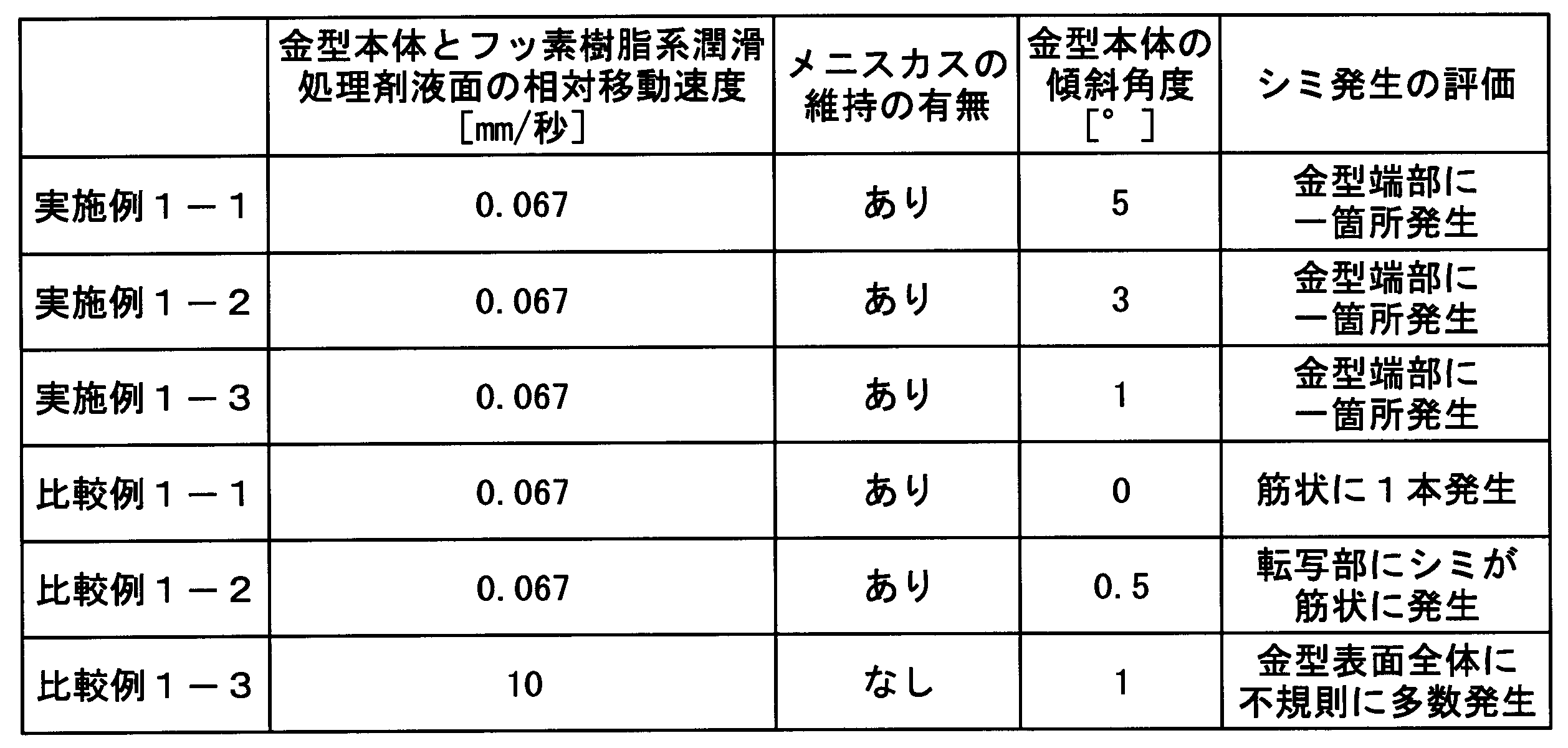
潤滑処理剤21として、リン酸エステル化合物(日光ケミカル社製、「TDP8」)を純水に溶解し、リン酸エステル化合物の濃度が0.1質量%である水溶液(リン酸エステル系潤滑処理剤)を用いた。また、金型本体11の傾斜角度を2°に変更し、相対移動速度の平均値を0.0046mm/秒に変更した。それ以外は実施例1-1と同様にロール金型を製造し、シミ発生の評価を行った。結果を表2に示す。
潤滑処理剤21として、リン酸エステル化合物(日光ケミカル社製、「TDP8」)を純水に溶解し、リン酸エステル化合物の濃度が0.1質量%である水溶液(リン酸エステル系潤滑処理剤)を用いた。また、金型本体11の傾斜角度を1°に変更し、相対移動速度の平均値を0.0046mm/秒に変更した。それ以外は実施例1-1と同様にロール金型を製造し、シミ発生の評価を行った。結果を表2に示す。
潤滑処理剤21として、リン酸エステル化合物(日光ケミカル社製、「TDP8」)を純水に溶解し、リン酸エステル化合物の濃度が0.1質量%である水溶液(リン酸エステル系潤滑処理剤)を用いた。また、金型本体11の傾斜角度を0°に変更し、相対移動速度の平均値を0.0046mm/秒に変更した。それ以外は実施例1-1と同様にロール金型を製造し、シミ発生の評価を行った。結果を表2に示す。
潤滑処理剤21として、リン酸エステル化合物(日光ケミカル社製、「TDP8」)を純水に溶解し、リン酸エステル化合物の濃度が0.1質量%である水溶液(リン酸エステル系潤滑処理剤)を用いた。また、金型本体11の傾斜角度を2°に変更した。それ以外は実施例1-1と同様にロール金型を製造し、シミ発生の評価を行った。結果を表2に示す。
なお、この相対移動速度は、金型本体11の表面と潤滑処理剤21の液面との間にメニスカスが維持されない状態で、金型本体11を潤滑処理剤21から取り出す速度である。
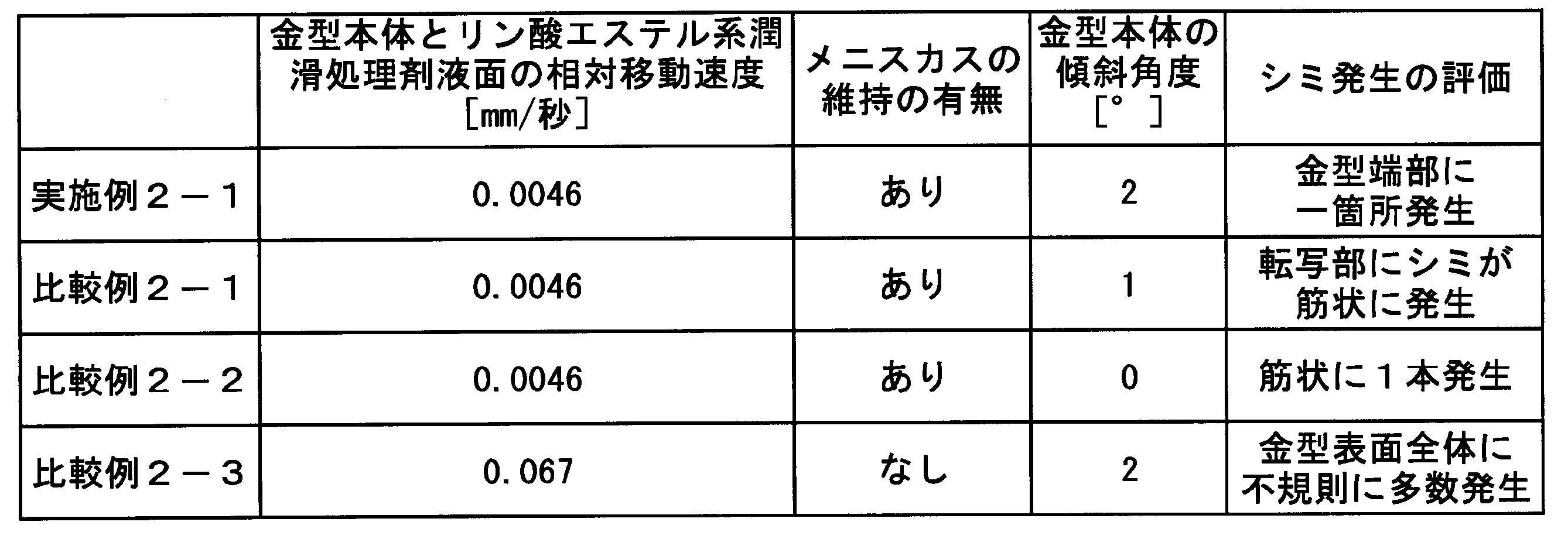
潤滑処理剤として有機溶剤液(フッ素樹脂系潤滑処理剤)を用い、金型本体の傾斜角度を0.5°にして潤滑処理剤から取り出した比較例1-2の場合、転写部にシミが筋状に発生した。
また、潤滑処理剤として水溶液(リン酸エステル系潤滑処理剤)を用い、金型本体の傾斜角度を1°にして潤滑処理剤から取り出した比較例2-1の場合、転写部にシミが筋状に発生した。
金型本体の表面と潤滑処理剤の液面との間にメニスカスを維持しない状態で、金型本体を潤滑処理剤から取り出した比較例1-3および比較例2-3の場合、取り出した直後は金型本体の表面全体から潤滑処理剤の液垂れが確認できる量の液が残存していた。比較例1-3および比較例2-3で得られたロール状金型は、メニスカスの分断によって生じた液滴残りによる不規則なシミが、金型表面全体に発生した。
11:金型本体、
21:潤滑処理剤、
40:物品、
41:フィルム、
43:凸部。
Claims (6)
- ロール状の金型本体の表面が処理剤で処理されたロール状金型を製造する方法であって、
前記金型本体を前記処理剤に浸漬させる浸漬工程と、
前記金型本体の中心軸を水平面に対して傾斜させた状態で、前記金型本体の一部を前記処理剤の液面から露出させる第1の取り出し工程と、
前記金型本体の露出した部分と前記処理剤の液面との間にメニスカスを維持した状態で、前記金型本体と前記処理剤の液面とを相対的に移動させ、前記金型本体を前記処理剤の液面からさらに露出させる第2の取り出し工程と、
前記金型本体の中心軸を水平面に対して傾斜させた状態で、前記金型本体の全てを前記処理剤から取り出す第3の取り出し工程とを有し、
前記処理剤が有機溶剤液であり、
前記第3の取り出し工程において、前記金型本体の中心軸を水平面に対して0.6°以上傾斜させる、ロール状金型の製造方法。 - ロール状の金型本体の表面が処理剤で処理されたロール状金型を製造する方法であって、
前記金型本体を前記処理剤に浸漬させる浸漬工程と、
前記金型本体の中心軸を水平面に対して傾斜させた状態で、前記金型本体の一部を前記処理剤の液面から露出させる第1の取り出し工程と、
前記金型本体の露出した部分と前記処理剤の液面との間にメニスカスを維持した状態で、前記金型本体と前記処理剤の液面とを相対的に移動させ、前記金型本体を前記処理剤の液面からさらに露出させる第2の取り出し工程と、
前記金型本体の中心軸を水平面に対して傾斜させた状態で、前記金型本体の全てを前記処理剤から取り出す第3の取り出し工程とを有し、
前記処理剤が水溶液であり、
前記第3の取り出し工程において、前記金型本体の中心軸を水平面に対して2°以上傾斜させる、ロール状金型の製造方法。 - 前記第1の取り出し工程、第2の取り出し工程、および第3の取り出し工程において、前記金型本体の中心軸を水平面に対して傾斜させる、請求項1または2に記載のロール状金型の製造方法。
- 前記浸漬工程の前に、前記金型本体の表面に微細凹凸構造を形成する微細凹凸構造形成工程をさらに有する、請求項1または2に記載のロール状金型の製造方法。
- 前記微細凹凸構造は、陽極酸化処理により形成される、請求項4に記載のロール状金型の製造方法。
- 請求項4に記載のロール状金型の製造方法により得られた、ロール状金型の表面の微細凹凸構造を物品本体の表面に転写する転写工程を有する、微細凹凸構造を表面に有する物品の製造方法。
Priority Applications (3)
| Application Number | Priority Date | Filing Date | Title |
|---|---|---|---|
| US14/126,444 US8940177B2 (en) | 2011-06-22 | 2012-06-20 | Method of manufacturing roll-shaped mold and method of manufacturing product having concave-convex microstructure on surface thereof |
| KR1020147001669A KR20140027495A (ko) | 2011-06-22 | 2012-06-20 | 롤상 금형의 제조방법, 및 미세 요철 구조를 표면에 갖는 물품의 제조방법 |
| CN201280030220.8A CN103619563A (zh) | 2011-06-22 | 2012-06-20 | 辊状模具的制造方法和表面具有微细凹凸结构的物品的制造方法 |
Applications Claiming Priority (2)
| Application Number | Priority Date | Filing Date | Title |
|---|---|---|---|
| JP2011-138300 | 2011-06-22 | ||
| JP2011138300 | 2011-06-22 |
Publications (1)
| Publication Number | Publication Date |
|---|---|
| WO2012176794A1 true WO2012176794A1 (ja) | 2012-12-27 |
Family
ID=47422626
Family Applications (1)
| Application Number | Title | Priority Date | Filing Date |
|---|---|---|---|
| PCT/JP2012/065711 Ceased WO2012176794A1 (ja) | 2011-06-22 | 2012-06-20 | ロール状金型の製造方法、および微細凹凸構造を表面に有する物品の製造方法 |
Country Status (6)
| Country | Link |
|---|---|
| US (1) | US8940177B2 (ja) |
| JP (1) | JPWO2012176794A1 (ja) |
| KR (1) | KR20140027495A (ja) |
| CN (1) | CN103619563A (ja) |
| TW (1) | TW201302438A (ja) |
| WO (1) | WO2012176794A1 (ja) |
Cited By (2)
| Publication number | Priority date | Publication date | Assignee | Title |
|---|---|---|---|---|
| JP2014184626A (ja) * | 2013-03-22 | 2014-10-02 | Mitsubishi Rayon Co Ltd | ロール状モールドの製造方法、および複数の凸部を表面に有する物品の製造方法 |
| KR20160130280A (ko) | 2014-04-08 | 2016-11-10 | 미쯔비시 레이온 가부시끼가이샤 | 몰드의 제조 방법 및 롤 형상 몰드의 제조 장치, 및 미세 요철 구조를 표면에 갖는 물품의 제조 방법 |
Families Citing this family (3)
| Publication number | Priority date | Publication date | Assignee | Title |
|---|---|---|---|---|
| TWI485452B (zh) * | 2012-10-31 | 2015-05-21 | Compal Electronics Inc | 複合導光板的製造方法 |
| CN113905890B (zh) * | 2019-06-03 | 2024-12-27 | 巴斯夫涂料有限公司 | 通过用于转移的压花工具的预处理将压花结构转移到涂料组合物的方法 |
| CN116277714B (zh) * | 2023-02-17 | 2023-09-01 | 宁波力松注塑科技有限公司 | 一种高端精密注塑机 |
Citations (4)
| Publication number | Priority date | Publication date | Assignee | Title |
|---|---|---|---|---|
| JPH08267464A (ja) * | 1995-03-28 | 1996-10-15 | Sakura Keikinzoku Kogyo Kk | 金型及びその表面処理方法 |
| JP2008081547A (ja) * | 2006-09-26 | 2008-04-10 | Arakawa Chem Ind Co Ltd | アルコキシシリル基含有シラン変性フッ素樹脂、アルコキシシリル基含有シラン変性フッ素樹脂組成物、アルコキシシリル基含有シラン変性フッ素樹脂組成物を含有するコーティング剤、フッ素樹脂−シリカハイブリッド硬化物およびそれを用いてなる積層体 |
| JP2010253820A (ja) * | 2009-04-24 | 2010-11-11 | Kanagawa Acad Of Sci & Technol | スタンパ製造用アルミニウム基材およびスタンパの製造方法 |
| JP2011025683A (ja) * | 2009-07-03 | 2011-02-10 | Mitsubishi Rayon Co Ltd | モールドの製造方法 |
Family Cites Families (6)
| Publication number | Priority date | Publication date | Assignee | Title |
|---|---|---|---|---|
| US4911226A (en) * | 1987-08-13 | 1990-03-27 | The Standard Oil Company | Method and apparatus for continuously casting strip steel |
| TWI225246B (en) * | 2003-05-21 | 2004-12-11 | Fan-Gang Tseng | Micro optical pickup head module, method of manufacturing the same and method of manufacturing the objective lens of the same |
| JP4800860B2 (ja) * | 2006-06-16 | 2011-10-26 | 富士フイルム株式会社 | 微細構造体の製造方法および微細構造体 |
| TW200928598A (en) * | 2007-12-24 | 2009-07-01 | Ind Tech Res Inst | Inclined exposure lithography system |
| JP2009292089A (ja) * | 2008-06-06 | 2009-12-17 | Nitto Denko Corp | 成形型及びそれを用いて成形したマイクロレンズ |
| US20110048958A1 (en) * | 2009-09-02 | 2011-03-03 | Gm Global Technology Operations, Inc. | Methods of reducing surface roughness and improving oxide coating thickness uniformity for anodized aluminum-silicon alloys |
-
2012
- 2012-06-20 JP JP2012531154A patent/JPWO2012176794A1/ja active Pending
- 2012-06-20 US US14/126,444 patent/US8940177B2/en not_active Expired - Fee Related
- 2012-06-20 CN CN201280030220.8A patent/CN103619563A/zh active Pending
- 2012-06-20 WO PCT/JP2012/065711 patent/WO2012176794A1/ja not_active Ceased
- 2012-06-20 TW TW101121993A patent/TW201302438A/zh unknown
- 2012-06-20 KR KR1020147001669A patent/KR20140027495A/ko not_active Abandoned
Patent Citations (4)
| Publication number | Priority date | Publication date | Assignee | Title |
|---|---|---|---|---|
| JPH08267464A (ja) * | 1995-03-28 | 1996-10-15 | Sakura Keikinzoku Kogyo Kk | 金型及びその表面処理方法 |
| JP2008081547A (ja) * | 2006-09-26 | 2008-04-10 | Arakawa Chem Ind Co Ltd | アルコキシシリル基含有シラン変性フッ素樹脂、アルコキシシリル基含有シラン変性フッ素樹脂組成物、アルコキシシリル基含有シラン変性フッ素樹脂組成物を含有するコーティング剤、フッ素樹脂−シリカハイブリッド硬化物およびそれを用いてなる積層体 |
| JP2010253820A (ja) * | 2009-04-24 | 2010-11-11 | Kanagawa Acad Of Sci & Technol | スタンパ製造用アルミニウム基材およびスタンパの製造方法 |
| JP2011025683A (ja) * | 2009-07-03 | 2011-02-10 | Mitsubishi Rayon Co Ltd | モールドの製造方法 |
Cited By (2)
| Publication number | Priority date | Publication date | Assignee | Title |
|---|---|---|---|---|
| JP2014184626A (ja) * | 2013-03-22 | 2014-10-02 | Mitsubishi Rayon Co Ltd | ロール状モールドの製造方法、および複数の凸部を表面に有する物品の製造方法 |
| KR20160130280A (ko) | 2014-04-08 | 2016-11-10 | 미쯔비시 레이온 가부시끼가이샤 | 몰드의 제조 방법 및 롤 형상 몰드의 제조 장치, 및 미세 요철 구조를 표면에 갖는 물품의 제조 방법 |
Also Published As
| Publication number | Publication date |
|---|---|
| KR20140027495A (ko) | 2014-03-06 |
| CN103619563A (zh) | 2014-03-05 |
| JPWO2012176794A1 (ja) | 2015-02-23 |
| TW201302438A (zh) | 2013-01-16 |
| US8940177B2 (en) | 2015-01-27 |
| US20140110371A1 (en) | 2014-04-24 |
Similar Documents
| Publication | Publication Date | Title |
|---|---|---|
| JP5898719B2 (ja) | スタンパの製造方法、成形体の製造方法 | |
| EP2636501B1 (en) | Method for producing article having fine concavo-convex structure on surface | |
| JP5742220B2 (ja) | フィルムの製造方法 | |
| CN104870694B (zh) | 多孔阳极氧化铝的制造方法、和表面具有微细凹凸结构的成形体的制造方法、以及表面具有微细凹凸结构的成形体 | |
| CN104350184B (zh) | 模具的制造方法和表面具有微细凹凸结构的成形体的制造方法 | |
| JP5156146B2 (ja) | 光透過性フィルムの製造方法、活性エネルギー線硬化性組成物 | |
| WO2011132771A1 (ja) | モールド、その製造方法、微細凹凸構造を表面に有する物品およびその製造方法 | |
| WO2012176794A1 (ja) | ロール状金型の製造方法、および微細凹凸構造を表面に有する物品の製造方法 | |
| CN104884218A (zh) | 光学物品、用于制造光学物品的模具和模具的制造方法 | |
| JP5474401B2 (ja) | スタンパ製造用アルミニウム基材およびスタンパの製造方法 | |
| CN102791454B (zh) | 模具的制造方法及表面具有微细凹凸结构的物品的制造方法 | |
| CN102666055B (zh) | 有机系脱模剂的性能评价方法、模具的制造方法和表面具有微细凹凸结构的透明薄膜的制造方法 | |
| JP6455127B2 (ja) | 透明フィルムの製造方法 | |
| WO2012105539A1 (ja) | 活性エネルギー線硬化性組成物、および微細凹凸構造を表面に有する透明フィルムの製造方法 | |
| JP6057130B2 (ja) | ロール状モールドの製造方法、および複数の凸部を表面に有する物品の製造方法 | |
| JP2013224015A (ja) | 光透過性フィルムおよびその製造方法 | |
| JP2014069533A (ja) | ロール状の金型の被覆処理方法、ロール状の金型の製造方法、表面に微細凹凸構造を有する部材の製造方法、及び金型の被覆処理装置 | |
| JP2013182007A (ja) | 微細凹凸構造を表面に有する物品の製造方法および製造装置 | |
| JP2015101780A (ja) | モールドの製造方法、および微細凹凸構造を表面に有する成形体とその製造方法 | |
| JP5751535B2 (ja) | 金型の洗浄方法、及び、物品の製造方法 | |
| JP2013007997A (ja) | 微細凹凸構造を表面に有する物品、およびその製造方法 | |
| JP5877006B2 (ja) | モールドの製造方法、および微細凹凸構造を表面に有する成形体の製造方法 |
Legal Events
| Date | Code | Title | Description |
|---|---|---|---|
| ENP | Entry into the national phase |
Ref document number: 2012531154 Country of ref document: JP Kind code of ref document: A |
|
| 121 | Ep: the epo has been informed by wipo that ep was designated in this application |
Ref document number: 12802103 Country of ref document: EP Kind code of ref document: A1 |
|
| WWE | Wipo information: entry into national phase |
Ref document number: 14126444 Country of ref document: US |
|
| NENP | Non-entry into the national phase |
Ref country code: DE |
|
| ENP | Entry into the national phase |
Ref document number: 20147001669 Country of ref document: KR Kind code of ref document: A |
|
| 122 | Ep: pct application non-entry in european phase |
Ref document number: 12802103 Country of ref document: EP Kind code of ref document: A1 |