WO2012176323A1 - 車両の駆動制御装置 - Google Patents
車両の駆動制御装置 Download PDFInfo
- Publication number
- WO2012176323A1 WO2012176323A1 PCT/JP2011/064482 JP2011064482W WO2012176323A1 WO 2012176323 A1 WO2012176323 A1 WO 2012176323A1 JP 2011064482 W JP2011064482 W JP 2011064482W WO 2012176323 A1 WO2012176323 A1 WO 2012176323A1
- Authority
- WO
- WIPO (PCT)
- Prior art keywords
- driving force
- vehicle
- prime mover
- driving
- suppression
- Prior art date
- Legal status (The legal status is an assumption and is not a legal conclusion. Google has not performed a legal analysis and makes no representation as to the accuracy of the status listed.)
- Ceased
Links
Images

Classifications
-
- B—PERFORMING OPERATIONS; TRANSPORTING
- B60—VEHICLES IN GENERAL
- B60W—CONJOINT CONTROL OF VEHICLE SUB-UNITS OF DIFFERENT TYPE OR DIFFERENT FUNCTION; CONTROL SYSTEMS SPECIALLY ADAPTED FOR HYBRID VEHICLES; ROAD VEHICLE DRIVE CONTROL SYSTEMS FOR PURPOSES NOT RELATED TO THE CONTROL OF A PARTICULAR SUB-UNIT
- B60W10/00—Conjoint control of vehicle sub-units of different type or different function
- B60W10/10—Conjoint control of vehicle sub-units of different type or different function including control of change-speed gearings
-
- B—PERFORMING OPERATIONS; TRANSPORTING
- B60—VEHICLES IN GENERAL
- B60W—CONJOINT CONTROL OF VEHICLE SUB-UNITS OF DIFFERENT TYPE OR DIFFERENT FUNCTION; CONTROL SYSTEMS SPECIALLY ADAPTED FOR HYBRID VEHICLES; ROAD VEHICLE DRIVE CONTROL SYSTEMS FOR PURPOSES NOT RELATED TO THE CONTROL OF A PARTICULAR SUB-UNIT
- B60W10/00—Conjoint control of vehicle sub-units of different type or different function
- B60W10/04—Conjoint control of vehicle sub-units of different type or different function including control of propulsion units
-
- B—PERFORMING OPERATIONS; TRANSPORTING
- B60—VEHICLES IN GENERAL
- B60W—CONJOINT CONTROL OF VEHICLE SUB-UNITS OF DIFFERENT TYPE OR DIFFERENT FUNCTION; CONTROL SYSTEMS SPECIALLY ADAPTED FOR HYBRID VEHICLES; ROAD VEHICLE DRIVE CONTROL SYSTEMS FOR PURPOSES NOT RELATED TO THE CONTROL OF A PARTICULAR SUB-UNIT
- B60W10/00—Conjoint control of vehicle sub-units of different type or different function
- B60W10/04—Conjoint control of vehicle sub-units of different type or different function including control of propulsion units
- B60W10/06—Conjoint control of vehicle sub-units of different type or different function including control of propulsion units including control of combustion engines
-
- B—PERFORMING OPERATIONS; TRANSPORTING
- B60—VEHICLES IN GENERAL
- B60W—CONJOINT CONTROL OF VEHICLE SUB-UNITS OF DIFFERENT TYPE OR DIFFERENT FUNCTION; CONTROL SYSTEMS SPECIALLY ADAPTED FOR HYBRID VEHICLES; ROAD VEHICLE DRIVE CONTROL SYSTEMS FOR PURPOSES NOT RELATED TO THE CONTROL OF A PARTICULAR SUB-UNIT
- B60W30/00—Purposes of road vehicle drive control systems not related to the control of a particular sub-unit, e.g. of systems using conjoint control of vehicle sub-units
- B60W30/18—Propelling the vehicle
- B60W30/18009—Propelling the vehicle related to particular drive situations
- B60W30/18027—Drive off, accelerating from standstill
-
- B—PERFORMING OPERATIONS; TRANSPORTING
- B60—VEHICLES IN GENERAL
- B60W—CONJOINT CONTROL OF VEHICLE SUB-UNITS OF DIFFERENT TYPE OR DIFFERENT FUNCTION; CONTROL SYSTEMS SPECIALLY ADAPTED FOR HYBRID VEHICLES; ROAD VEHICLE DRIVE CONTROL SYSTEMS FOR PURPOSES NOT RELATED TO THE CONTROL OF A PARTICULAR SUB-UNIT
- B60W50/00—Details of control systems for road vehicle drive control not related to the control of a particular sub-unit, e.g. process diagnostic or vehicle driver interfaces
- B60W50/08—Interaction between the driver and the control system
- B60W50/087—Interaction between the driver and the control system where the control system corrects or modifies a request from the driver
-
- B—PERFORMING OPERATIONS; TRANSPORTING
- B60—VEHICLES IN GENERAL
- B60W—CONJOINT CONTROL OF VEHICLE SUB-UNITS OF DIFFERENT TYPE OR DIFFERENT FUNCTION; CONTROL SYSTEMS SPECIALLY ADAPTED FOR HYBRID VEHICLES; ROAD VEHICLE DRIVE CONTROL SYSTEMS FOR PURPOSES NOT RELATED TO THE CONTROL OF A PARTICULAR SUB-UNIT
- B60W50/00—Details of control systems for road vehicle drive control not related to the control of a particular sub-unit, e.g. process diagnostic or vehicle driver interfaces
- B60W50/08—Interaction between the driver and the control system
- B60W50/10—Interpretation of driver requests or demands
-
- B—PERFORMING OPERATIONS; TRANSPORTING
- B60—VEHICLES IN GENERAL
- B60W—CONJOINT CONTROL OF VEHICLE SUB-UNITS OF DIFFERENT TYPE OR DIFFERENT FUNCTION; CONTROL SYSTEMS SPECIALLY ADAPTED FOR HYBRID VEHICLES; ROAD VEHICLE DRIVE CONTROL SYSTEMS FOR PURPOSES NOT RELATED TO THE CONTROL OF A PARTICULAR SUB-UNIT
- B60W2540/00—Input parameters relating to occupants
- B60W2540/10—Accelerator pedal position
-
- B—PERFORMING OPERATIONS; TRANSPORTING
- B60—VEHICLES IN GENERAL
- B60W—CONJOINT CONTROL OF VEHICLE SUB-UNITS OF DIFFERENT TYPE OR DIFFERENT FUNCTION; CONTROL SYSTEMS SPECIALLY ADAPTED FOR HYBRID VEHICLES; ROAD VEHICLE DRIVE CONTROL SYSTEMS FOR PURPOSES NOT RELATED TO THE CONTROL OF A PARTICULAR SUB-UNIT
- B60W2540/00—Input parameters relating to occupants
- B60W2540/16—Ratio selector position
-
- B—PERFORMING OPERATIONS; TRANSPORTING
- B60—VEHICLES IN GENERAL
- B60W—CONJOINT CONTROL OF VEHICLE SUB-UNITS OF DIFFERENT TYPE OR DIFFERENT FUNCTION; CONTROL SYSTEMS SPECIALLY ADAPTED FOR HYBRID VEHICLES; ROAD VEHICLE DRIVE CONTROL SYSTEMS FOR PURPOSES NOT RELATED TO THE CONTROL OF A PARTICULAR SUB-UNIT
- B60W2710/00—Output or target parameters relating to a particular sub-units
- B60W2710/06—Combustion engines, Gas turbines
- B60W2710/0666—Engine torque
Definitions
- the present invention relates to a vehicle drive control device.
- a vehicle such as an automobile includes a control unit that adjusts the driving force output from the prime mover according to the accelerator operation by the driver, and the driving force output from the prime mover is It travels by transmitting to wheels. Further, the vehicle is provided with a shift mechanism that can be switched between a driving position and a non-driving position by a driver. When the shift mechanism is in the driving position, the driving force is transmitted from the prime mover to the wheels. On the other hand, when the shift mechanism is in the non-driving position, transmission of the driving force from the prime mover to the wheels is interrupted.
- a driver who tries to run a vehicle in a stopped state usually operates the accelerator in an off state to an on state after switching the shift mechanism from a non-drive position to a drive position.
- the on operation from the accelerator off state may be faster than the shift mechanism switching from the non-drive position to the drive position.
- an operation different from the normal operation of switching the shift mechanism from the non-drive position to the drive position with the accelerator on is actually performed. .
- the behavior of the vehicle assumed by the driver may be inconsistent with the actual behavior of the vehicle.
- the driver intends to start running the vehicle when the accelerator is turned on, but in actuality, when the shift mechanism is switched from the non-drive position to the drive position after the accelerator is turned on, the prime mover Is transmitted to the wheels, and the vehicle starts to travel.
- the shift mechanism is switched from the non-driving position to the driving position with the accelerator turned on, the driving force of the prime mover is transmitted to the wheels and the vehicle starts to run, and the driver feels uncomfortable. It is unavoidable to remember the vehicle, which in turn reduces the drivability of the vehicle.
- Patent Document 1 the pedal force or the depression speed of the accelerator pedal exceeds the detection level when the gear ratio of the transmission provided on the transmission path of the driving force between the prime mover and the wheels is large.
- a technique for reducing the driving force output from the prime mover until the vehicle becomes inoperable is disclosed. Even if such a technique of Patent Document 1 is applied, it is impossible to suppress a decrease in drivability of the vehicle due to the driver's uncomfortable feeling under the above-described situation. This is because even when the technique of Patent Document 1 is applied, when the shift mechanism is switched from the non-driving position to the driving position with the accelerator turned on, the driving force output from the prime mover is not necessarily reduced. This is because there is a high possibility that the driving force of the prime mover is transmitted to the wheels and the vehicle starts to travel at that time.
- the present invention has been made in view of such a situation, and an object thereof is to suppress a driver's uncomfortable feeling when the shift mechanism is switched from the non-driving position to the driving position with the accelerator turned on. Therefore, an object of the present invention is to provide a vehicle drive control device that can suppress a decrease in vehicle drivability due to such uncomfortable feeling.
- the vehicle drive control device provides a driving force from the prime mover according to the operation of the accelerator when the shift mechanism is switched from the non-drive position to the drive position while the accelerator is turned on. Is output, the driving force suppressing process for suppressing the driving force is executed.
- the situation where the shift mechanism is switched from the non-driving position to the driving position while the accelerator is turned on is when the driver is rushing to drive a vehicle in a stopped state.
- the accelerator is turned on from the off state before the shift mechanism is switched from the non-drive position to the drive position without being aware of it.
- the suppression degree of the driving force output from the prime mover is changed according to the acceleration of the vehicle.
- the degree of suppression of the driving force output from the prime mover can be increased as the acceleration of the vehicle increases. More specifically, when the vehicle acceleration is less than the determination value, the degree of suppression of the driving force output from the prime mover is set to “0”, while when the vehicle acceleration is greater than or equal to the determination value, the drive output from the prime mover. It is conceivable that the degree of force suppression is greater than “0”.
- the determination value is preferably variably set according to the vehicle speed.
- the driving force can be suppressed so that the driver does not feel uncomfortable while avoiding unnecessary suppression of the driving force output from the prime mover.
- the driver may repeatedly switch the shift mechanism between the non-driving position and the driving position, at which time the accelerator is turned on. In this state, the shift mechanism may be switched from the non-drive position to the drive position.
- the degree of suppression of the driving force output from the prime mover through the driving force suppression process is reduced. Therefore, it is possible to suppress the suppression of the driving force by the driving force suppression process from hindering the vehicle from escaping from the mud path, and to improve the drivability of the vehicle when the vehicle is evacuated from the mud path.
- the driving force suppression process when executed by the control unit, when the vehicle speed is equal to or higher than the reference value, the output from the prime mover is not affected by the magnitude relationship between the acceleration of the vehicle and the determination value.
- the degree of suppression of the driving force is made larger than “0”. In this case, when the driving force suppression process is executed, when the vehicle speed is high, that is, when the driver tends to feel uncomfortable, the uncomfortable feeling can be suppressed by accurately suppressing the driving force output from the prime mover.
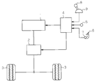
- an automobile has an internal combustion engine as a prime mover 1. And if the driving force output from the motor
- the transmission 2 includes a plurality of gears, and the combination of the plurality of gears can be changed so as to form any one of a plurality of predetermined gears. Further, the transmission 2 can transmit the driving force output from the prime mover 1 to the wheels 3 or can block the transmission of the driving force. That is, the transmission 2 functions as a driving force transmission / cutoff device.
- the electronic control unit 4 executes various controls related to the prime mover 1 and the transmission 2 and the like.
- the electronic control unit 4 includes a vehicle speed sensor 5 that detects the vehicle speed of the vehicle, an accelerator position sensor 7 that detects an operation amount (accelerator operation amount) of an accelerator pedal 6 that is depressed by a vehicle driver, Various sensors such as a shift position sensor 9 that outputs a signal corresponding to the position of the shift lever 8 (shift mechanism) operated by the driver are connected.
- the electronic control device 4 is connected to a drive circuit for driving the prime mover 1 and a drive circuit for driving the transmission 2.
- the electronic control unit 4 adjusts the driving force output from the prime mover 1 according to the accelerator operation amount. Further, the electronic control unit 4 switches the gear position in the transmission 2 and transmits and interrupts the driving force between the prime mover 1 and the wheels 3 based on the accelerator operation amount, the vehicle speed, and the operation position of the shift lever 8. I do. Incidentally, the shift lever 8 is switched to one of a plurality of operation positions such as a parking position, a reverse position, a neutral position, and a drive position.
- driving modes of the transmission 2 for each operation position of the shift lever 8 will be listed.
- the shift lever 8 When the shift lever 8 is switched to the parking position, the rotation of the wheel 3 is prohibited due to the meshing of the gear in the transmission 2, and the transmission of the driving force output from the prime mover 1 to the wheel 3 is interrupted. 2 is driven through the electronic control unit 4.
- the shift lever 8 When the shift lever 8 is switched to the neutral position, the prohibition of rotation of the wheel 3 due to the meshing of the gears in the transmission 2 described above is released, and transmission of the driving force output from the prime mover 1 to the wheel 3 is interrupted.
- the transmission 2 is driven through the electronic control unit 4. Therefore, the parking position or neutral position of the shift lever 8 is an operating position (hereinafter referred to as a non-driving position) for interrupting transmission of the driving force output from the prime mover 1 to the wheels 3.
- the transmission 2 When the shift lever 8 is switched to the drive position, the transmission 2 is driven through the electronic control unit 4 so that the driving force output from the prime mover 1 is transmitted to the wheels 3 in the forward rotation direction.
- the shift lever 8 When the shift lever 8 is switched to the reverse position, the transmission 2 is driven through the electronic control unit 4 so that the driving force output from the prime mover 1 is transmitted to the wheels 3 in the reverse rotation direction. Accordingly, the drive position and the reverse position of the shift lever 8 become an operation position for transmitting the driving force output from the prime mover 1 to the wheels 3 (hereinafter referred to as a driving position).
- a driver who tries to run a vehicle in a stopped state normally switches the shift lever 8 from a non-driving position such as a parking position to a driving position such as a driving position or a reverse position and then is in an off state. Depress the accelerator pedal 6 to the on state.
- the operation (on operation) of the accelerator pedal 6 from the off state to the on state is faster than the operation of switching the shift lever 8 from the non-drive position to the drive position.
- the operation is actually different from the normal operation of switching the shift lever 8 from the non-drive position to the drive position with the accelerator pedal 6 turned on. Is done.
- the behavior of the automobile assumed by the driver may be different from the actual behavior of the automobile.
- the driver intends to start running the vehicle when the accelerator pedal 6 is turned on, but actually the shift lever 8 is switched from the non-drive position to the drive position after the accelerator pedal 6 is turned on.
- the driving force of the prime mover 1 is transmitted to the wheels 3 and the vehicle starts to travel.
- the shift lever 8 is switched from the non-driving position to the driving position with the accelerator pedal 6 turned on, the driving force of the prime mover 1 is transmitted to the wheels 3 and the vehicle starts to travel.
- the accelerator pedal 6 when the shift lever 8 is switched from the non-drive position to the drive position with the accelerator pedal 6 turned on, when the driving force is output from the prime mover 1 according to the accelerator operation amount, A driving force suppression process for suppressing the driving force is executed. Accordingly, the accelerator pedal 6 is operated prior to the operation of switching the shift lever 8 from the non-driving position to the driving position without the driver being aware of it, such as when the driver is about to drive the vehicle in a stopped state. When a situation occurs in which the ON operation is performed from the OFF state, the driving force suppression process is executed.
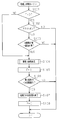
- This driving force suppression routine is periodically executed through the electronic control unit 4 by, for example, a time interruption every predetermined time.
- this routine first, it is determined whether or not the flag F used for determining whether or not the driving force suppression process is being executed is 0 (stopped) (S101). If the determination is affirmative, it is determined whether or not the accelerator pedal 6 has been turned on (S102), and whether or not the shift lever 8 has been switched from the non-driving position to the driving position (S103). Done. As a situation where the shift lever 8 is switched from the non-drive position to the drive position, a situation where the driver switches the shift lever 8 from the parking position or neutral position to the drive position or reverse position is conceivable. Further, when the neutral position is, for example, between the drive position and the reverse position, the situation in which the driver repeatedly switches the shift lever 8 between the drive position and the reverse position also occurs.
- the required driving force calculated based on the accelerator operation amount as the driving force to be output from the prime mover 1 according to the accelerator operation amount is the control driving force that is the driving force after suppression by the driving force suppression processing. It is determined whether or not it has become less than (S106: YES). For example, when the driver's on-operation of the accelerator pedal 6 is canceled and the accelerator operation amount becomes “0” due to the off-state, the requested driving force becomes less than the control driving force and affirmative is obtained in S106. Judgment is made. If an affirmative determination is made here, the driving force suppression process is terminated (S107).
- the driving force output from the prime mover 1 thereafter becomes the required driving force based on the accelerator operation amount. To be adjusted. Further, after the driving force suppression process is completed, the flag F is set to “0 (stopped)” (S108).
- the driving force output from the prime mover 1 is realized by reducing the driving force by a reduction amount. Accordingly, as the reduction amount is increased, the degree of suppression of the driving force output from the prime mover 1 by the driving force reduction process is increased.
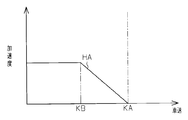
- the degree of suppression of the driving force output from the prime mover 1 by the driving force reduction process is changed according to the acceleration of the vehicle obtained based on the detection signal of the vehicle speed sensor 5. For example, the amount of reduction is increased as the acceleration of the automobile increases, and the degree of suppression of the driving force output from the prime mover 1 is increased. More specifically, for example, as shown in FIG.
- the driving force can be suppressed so that the driver does not feel uncomfortable while avoiding unnecessary suppression of the driving force output from the prime mover 1.
- the driver may repeatedly perform the switching operation of the shift lever 8 between the non-driving position and the driving position.
- the shift lever 8 may be switched from the non-driving position to the driving position in a state in which is turned on.
- the degree of suppression of the driving force output from the prime mover 1 through the driving force suppression process is reduced. Accordingly, it is possible to suppress the suppression of the driving force by the driving force suppression process from hindering the escape of the automobile from the mud road, and the drivability of the automobile can be improved when the automobile is escaped from the mud road.
- the determination value HA used in the driving force suppression process is preferably variably set so as to be an optimum value determined in advance by experiments or the like according to the vehicle speed.
- the determination value HA variably set according to the vehicle speed changes according to the vehicle speed as shown by a solid line in FIG. 4, for example.
- the determination value HA is set to an optimum value determined in advance through experiments or the like.
- the determination value HA is gradually reduced as the vehicle speed increases.
- the determination value HA is set to “0”.
- the driving force suppression process when executed, if the vehicle speed is equal to or higher than the reference value KA, the driving force output from the prime mover 1 is suppressed without being affected by the magnitude relationship between the acceleration of the vehicle and the determination value HA.
- the degree is made larger than “0” according to the acceleration of the automobile. That is, in order to make the degree of suppression of the driving force output from the prime mover 1 larger than “0” as described above, the reduction amount is set to a value larger than “0” according to the acceleration of the automobile.
- the driving force output from the prime mover 1 when the vehicle speed is larger than the reference value KA, that is, when the driver is likely to feel uncomfortable, the driving force output from the prime mover 1 is accurately suppressed to suppress the uncomfortable feeling. can do.
- the degree of suppression of the driving force output from the prime mover 1 by the driving force reduction process is changed according to the acceleration of the automobile. Specifically, when the acceleration of the automobile is less than the determination value HA, the degree of suppression of the driving force output from the prime mover 1 is set to “0”, while when the acceleration of the automobile is greater than or equal to the determination value HA, the acceleration is the determination value. The degree of suppression of the driving force output from the prime mover 1 becomes larger than “0” as it becomes larger than HA. By performing the driving force suppression process in this manner, the driving force can be suppressed so that the driver does not feel uncomfortable while avoiding unnecessary suppression of the driving force output from the prime mover 1.
- the determination value HA used in the driving force suppression process is variably set so as to be an optimum value determined in advance by experiments or the like according to the vehicle speed.
- the determination value HA is set to “0”. Therefore, if the vehicle speed is equal to or higher than the reference value KA when the driving force suppression process is executed, the acceleration of the vehicle and the determination value HA.
- the degree of suppression of the driving force output from the prime mover 1 is made greater than “0” in accordance with the acceleration of the vehicle. In this case, when executing the driving force suppression process, when the vehicle speed is larger than the reference value KA, that is, when the driver is likely to feel uncomfortable, the driving force output from the prime mover 1 is accurately suppressed to suppress the uncomfortable feeling. can do.
- variable setting based on the vehicle speed of the judgment value HA is not necessarily performed in the manner shown in FIG. 4, and can be arbitrarily changed according to the specifications of the automobile.
- the judgment value HA does not necessarily need to be variably set according to the vehicle speed, and may be fixed to an optimum value determined by experiments or the like.
- the amount of reduction in driving force in the driving force suppression process is variably set according to the acceleration of the vehicle, but such variable setting is not necessarily performed in the manner shown in FIG. It is possible to change to For example, when the acceleration is less than the determination value HA, the reduction amount can be variably set to be larger than “0”. Note that the amount of reduction when the acceleration is less than the determination value HA can be a constant value larger than “0” or a variable value that increases as the acceleration increases. Further, the amount of reduction when the acceleration is equal to or higher than the determination value HA may be a constant value larger than “0”.
- the above reduction amount does not necessarily need to be variably set according to the acceleration of the vehicle, and may be fixed to an optimum value determined by experiments or the like.
- the driving force suppression process when executed, the driving force output from the prime mover 1 is reduced by the reduction amount set to the optimum value regardless of the acceleration of the automobile.
- the degree of suppression of the driving force is constant regardless of the acceleration of the automobile.
- the situation in which it is determined in S103 of the driving force suppression routine shown in FIG. 2 that the shift lever 8 has been switched from the non-driving position to the driving position is not limited to the situation illustrated in the above embodiment, but for example, the following situation Can also be raised.
- a shift mechanism other than the shift lever 8 may be employed as a shift mechanism, such as a switch mechanism that switches between a drive position and a non-drive position by a button operation.
- the internal combustion engine was illustrated as the motor
- 1 ... prime mover, 2 ... transmission, 3 ... wheel, 4 ... electronic control device, 5 ... vehicle speed sensor, 6 ... accelerator pedal, 7 ... accelerator position sensor, 8 ... shift lever, 9 ... shift position sensor.
Landscapes
- Engineering & Computer Science (AREA)
- Automation & Control Theory (AREA)
- Transportation (AREA)
- Mechanical Engineering (AREA)
- Chemical & Material Sciences (AREA)
- Combustion & Propulsion (AREA)
- Human Computer Interaction (AREA)
- Control Of Vehicle Engines Or Engines For Specific Uses (AREA)
- Hybrid Electric Vehicles (AREA)
- Combined Controls Of Internal Combustion Engines (AREA)
Abstract
Description
Claims (5)
- アクセルの操作に応じて原動機から出力される駆動力を調整する制御部と、駆動位置及び非駆動位置に選択的に切り換えられるシフト機構とを備え、前記シフト機構が前記駆動位置にあるときに前記原動機から車輪に駆動力を伝達する一方、前記シフト機構が前記非駆動位置にあるときには前記原動機から前記車輪への駆動力の伝達を遮断する、車両の駆動制御装置において、
前記制御部は、前記アクセルがオン操作された状態で前記シフト機構が前記非駆動位置から前記駆動位置に切り換えられたとき、前記原動機から出力される駆動力を抑制する駆動力抑制処理を実行する
ことを特徴とする車両の駆動制御装置。 - 前記制御部は、前記駆動力抑制処理を実行する際、前記原動機から出力される駆動力の抑制度合いを車両の加速度に応じて変更する
請求項1記載の車両の駆動制御装置。 - 前記制御部は、前記駆動力抑制処理を実行する際、前記車両の加速度が判定値未満であるときには前記原動機から出力される駆動力の抑制度合いを「0」とする一方、前記車両の加速度が判定値以上であるときには前記原動機から出力される駆動力の抑制度合いを「0」よりも大きくする
請求項2記載の車両の駆動制御装置。 - 前記制御部は、前記駆動力抑制処理を実行する際、前記判定値を車速に応じて可変設定する
請求項3記載の車両の駆動制御装置。 - 前記制御部は、前記駆動力抑制処理を実行する際、車速が基準値以上であるときには、車両の加速度と前記判定値との大小関係から影響を受けることなく、前記原動機から出力される駆動力の抑制度合いを「0」よりも大きくする
請求項3記載の車両の駆動制御装置。
Priority Applications (5)
| Application Number | Priority Date | Filing Date | Title |
|---|---|---|---|
| JP2013521393A JP5704235B2 (ja) | 2011-06-23 | 2011-06-23 | 車両の駆動制御装置 |
| US14/126,639 US8838351B2 (en) | 2011-06-23 | 2011-06-23 | Vehicle drive control device |
| PCT/JP2011/064482 WO2012176323A1 (ja) | 2011-06-23 | 2011-06-23 | 車両の駆動制御装置 |
| BR112013032730-8A BR112013032730B1 (pt) | 2011-06-23 | 2011-06-23 | dispositivo de controle de acionamento de veículo |
| CN201180071712.7A CN103620194B (zh) | 2011-06-23 | 2011-06-23 | 车辆的驱动控制装置 |
Applications Claiming Priority (1)
| Application Number | Priority Date | Filing Date | Title |
|---|---|---|---|
| PCT/JP2011/064482 WO2012176323A1 (ja) | 2011-06-23 | 2011-06-23 | 車両の駆動制御装置 |
Publications (1)
| Publication Number | Publication Date |
|---|---|
| WO2012176323A1 true WO2012176323A1 (ja) | 2012-12-27 |
Family
ID=47422198
Family Applications (1)
| Application Number | Title | Priority Date | Filing Date |
|---|---|---|---|
| PCT/JP2011/064482 Ceased WO2012176323A1 (ja) | 2011-06-23 | 2011-06-23 | 車両の駆動制御装置 |
Country Status (5)
| Country | Link |
|---|---|
| US (1) | US8838351B2 (ja) |
| JP (1) | JP5704235B2 (ja) |
| CN (1) | CN103620194B (ja) |
| BR (1) | BR112013032730B1 (ja) |
| WO (1) | WO2012176323A1 (ja) |
Cited By (2)
| Publication number | Priority date | Publication date | Assignee | Title |
|---|---|---|---|---|
| US8852055B2 (en) | 2011-11-29 | 2014-10-07 | Toyota Jidosha Kabushiki Kaisha | Vehicle drive control apparatus |
| US9156462B2 (en) | 2011-12-02 | 2015-10-13 | Toyota Jidosha Kabushiki Kaisha | Drive control apparatus for vehicle |
Families Citing this family (4)
| Publication number | Priority date | Publication date | Assignee | Title |
|---|---|---|---|---|
| CN103620193B (zh) * | 2011-06-23 | 2015-11-25 | 丰田自动车株式会社 | 车辆的驱动控制装置 |
| DE102014009448B4 (de) * | 2014-06-25 | 2019-12-05 | Audi Ag | Prädiktive Ladezustandssteuerung einer Energiespeichereinrichtung eines elektrisch betriebenen Kraftfahrzeugs |
| JP7091816B2 (ja) * | 2018-05-08 | 2022-06-28 | トヨタ自動車株式会社 | 駆動力制御装置 |
| JP7200736B2 (ja) * | 2019-02-20 | 2023-01-10 | トヨタ自動車株式会社 | 駆動力制御装置 |
Citations (4)
| Publication number | Priority date | Publication date | Assignee | Title |
|---|---|---|---|---|
| JPH0796779A (ja) * | 1993-09-28 | 1995-04-11 | Mazda Motor Corp | 自動変速機の制御装置 |
| JP2004263741A (ja) * | 2003-02-28 | 2004-09-24 | Jatco Ltd | 自動変速機のクラッチ締結制御装置 |
| JP2004360567A (ja) * | 2003-06-04 | 2004-12-24 | Nissan Motor Co Ltd | 自動変速機のセレクトショック軽減装置 |
| JP2010018174A (ja) * | 2008-07-11 | 2010-01-28 | Toyota Motor Corp | ハイブリッド自動車およびその制御方法 |
Family Cites Families (6)
| Publication number | Priority date | Publication date | Assignee | Title |
|---|---|---|---|---|
| JPH0621582B2 (ja) | 1985-02-16 | 1994-03-23 | ダイハツ工業株式会社 | 自動車の走行制御方法 |
| DE19637210B4 (de) * | 1996-09-12 | 2007-05-24 | Siemens Ag | Antriebsstrangsteuerung für ein Kraftfahrzeug |
| JP4037506B2 (ja) * | 1998-03-12 | 2008-01-23 | 富士重工業株式会社 | 車両運動制御装置 |
| JP2000006682A (ja) * | 1998-06-24 | 2000-01-11 | Aisin Seiki Co Ltd | 定速走行装置 |
| JP4683023B2 (ja) * | 2007-08-21 | 2011-05-11 | 日産自動車株式会社 | 車両の加速ショック軽減装置 |
| CN103620193B (zh) | 2011-06-23 | 2015-11-25 | 丰田自动车株式会社 | 车辆的驱动控制装置 |
-
2011
- 2011-06-23 JP JP2013521393A patent/JP5704235B2/ja active Active
- 2011-06-23 WO PCT/JP2011/064482 patent/WO2012176323A1/ja not_active Ceased
- 2011-06-23 CN CN201180071712.7A patent/CN103620194B/zh not_active Expired - Fee Related
- 2011-06-23 BR BR112013032730-8A patent/BR112013032730B1/pt not_active IP Right Cessation
- 2011-06-23 US US14/126,639 patent/US8838351B2/en active Active
Patent Citations (4)
| Publication number | Priority date | Publication date | Assignee | Title |
|---|---|---|---|---|
| JPH0796779A (ja) * | 1993-09-28 | 1995-04-11 | Mazda Motor Corp | 自動変速機の制御装置 |
| JP2004263741A (ja) * | 2003-02-28 | 2004-09-24 | Jatco Ltd | 自動変速機のクラッチ締結制御装置 |
| JP2004360567A (ja) * | 2003-06-04 | 2004-12-24 | Nissan Motor Co Ltd | 自動変速機のセレクトショック軽減装置 |
| JP2010018174A (ja) * | 2008-07-11 | 2010-01-28 | Toyota Motor Corp | ハイブリッド自動車およびその制御方法 |
Cited By (2)
| Publication number | Priority date | Publication date | Assignee | Title |
|---|---|---|---|---|
| US8852055B2 (en) | 2011-11-29 | 2014-10-07 | Toyota Jidosha Kabushiki Kaisha | Vehicle drive control apparatus |
| US9156462B2 (en) | 2011-12-02 | 2015-10-13 | Toyota Jidosha Kabushiki Kaisha | Drive control apparatus for vehicle |
Also Published As
| Publication number | Publication date |
|---|---|
| BR112013032730B1 (pt) | 2020-10-20 |
| JP5704235B2 (ja) | 2015-04-22 |
| CN103620194A (zh) | 2014-03-05 |
| CN103620194B (zh) | 2016-03-16 |
| US8838351B2 (en) | 2014-09-16 |
| US20140136061A1 (en) | 2014-05-15 |
| JPWO2012176323A1 (ja) | 2015-02-23 |
| BR112013032730A2 (pt) | 2017-02-07 |
Similar Documents
| Publication | Publication Date | Title |
|---|---|---|
| JP5704235B2 (ja) | 車両の駆動制御装置 | |
| JP2014141119A (ja) | ハイブリッド車両の制御装置 | |
| JP5668850B2 (ja) | 車両の駆動制御装置 | |
| JP2014156140A (ja) | アクセルペダルの誤操作制御装置 | |
| JP2009077585A (ja) | モータトルク制御装置 | |
| US8751120B2 (en) | Driving control system for vehicle | |
| US9156462B2 (en) | Drive control apparatus for vehicle | |
| JP5019013B1 (ja) | 車両の駆動制御装置 | |
| JP5741424B2 (ja) | 車両の駆動制御装置 | |
| JP5810870B2 (ja) | 車両の駆動制御装置 | |
| JP6036328B2 (ja) | ハイブリッド車両の制御装置 | |
| JP2020131961A (ja) | 駆動力制御装置 | |
| JP2013224058A (ja) | ハイブリッド車両の発進制御装置 | |
| JP6187402B2 (ja) | 車両駆動ユニットの制御装置 | |
| JP2015197203A (ja) | 無段変速機の制御装置 | |
| JP4687726B2 (ja) | 車速制限装置 | |
| JP2013216152A (ja) | ハイブリッド車両の制御装置 | |
| JP2015067259A (ja) | 車両の駆動力制御装置 | |
| JP2015013540A (ja) | 車両の駆動力制御装置 |
Legal Events
| Date | Code | Title | Description |
|---|---|---|---|
| WWE | Wipo information: entry into national phase |
Ref document number: 201180071712.7 Country of ref document: CN |
|
| 121 | Ep: the epo has been informed by wipo that ep was designated in this application |
Ref document number: 11868092 Country of ref document: EP Kind code of ref document: A1 |
|
| ENP | Entry into the national phase |
Ref document number: 2013521393 Country of ref document: JP Kind code of ref document: A |
|
| WWE | Wipo information: entry into national phase |
Ref document number: 14126639 Country of ref document: US |
|
| NENP | Non-entry into the national phase |
Ref country code: DE |
|
| REG | Reference to national code |
Ref country code: BR Ref legal event code: B01A Ref document number: 112013032730 Country of ref document: BR |
|
| 122 | Ep: pct application non-entry in european phase |
Ref document number: 11868092 Country of ref document: EP Kind code of ref document: A1 |
|
| ENP | Entry into the national phase |
Ref document number: 112013032730 Country of ref document: BR Kind code of ref document: A2 Effective date: 20131219 |