WO2012173254A1 - 動作検出センサ - Google Patents
動作検出センサ Download PDFInfo
- Publication number
- WO2012173254A1 WO2012173254A1 PCT/JP2012/065425 JP2012065425W WO2012173254A1 WO 2012173254 A1 WO2012173254 A1 WO 2012173254A1 JP 2012065425 W JP2012065425 W JP 2012065425W WO 2012173254 A1 WO2012173254 A1 WO 2012173254A1
- Authority
- WO
- WIPO (PCT)
- Prior art keywords
- finger
- detection sensor
- motion detection
- arm
- base
- Prior art date
- Legal status (The legal status is an assumption and is not a legal conclusion. Google has not performed a legal analysis and makes no representation as to the accuracy of the status listed.)
- Ceased
Links
Images






Classifications
-
- A—HUMAN NECESSITIES
- A45—HAND OR TRAVELLING ARTICLES
- A45D—HAIRDRESSING OR SHAVING EQUIPMENT; EQUIPMENT FOR COSMETICS OR COSMETIC TREATMENTS, e.g. FOR MANICURING OR PEDICURING
- A45D29/00—Manicuring or pedicuring implements
-
- G—PHYSICS
- G01—MEASURING; TESTING
- G01L—MEASURING FORCE, STRESS, TORQUE, WORK, MECHANICAL POWER, MECHANICAL EFFICIENCY, OR FLUID PRESSURE
- G01L1/00—Measuring force or stress, in general
- G01L1/04—Measuring force or stress, in general by measuring elastic deformation of gauges, e.g. of springs
- G01L1/044—Measuring force or stress, in general by measuring elastic deformation of gauges, e.g. of springs of leaf springs
-
- A—HUMAN NECESSITIES
- A45—HAND OR TRAVELLING ARTICLES
- A45D—HAIRDRESSING OR SHAVING EQUIPMENT; EQUIPMENT FOR COSMETICS OR COSMETIC TREATMENTS, e.g. FOR MANICURING OR PEDICURING
- A45D44/00—Other cosmetic or toiletry articles, e.g. for hairdressers' rooms
Definitions
- the present invention relates to a motion detection sensor, and more particularly to a motion detection sensor that is mounted on a finger and detects its motion.
- cosmetics and makeup tools are used.
- a practitioner who performs makeup performs makeup by directly holding the cosmetic (for example, mascara, eyeliner, etc.).
- the practitioner may use makeup tools (various brushes such as lip brushes and teak brushes, makeup puffs, foundation sponges, and cotton).
- makeup tools When performing makeup in this way, the practitioner uses cosmetics and makeup tools (hereinafter collectively referred to as makeup tools, etc.) by hand. Therefore, it is important for a cosmetic tool or the like to improve the feeling of use when the practitioner directly holds it. In addition, it is desirable that the feeling of use of a cosmetic tool or the like can be quantitatively detected so that improvement in usability can be objectively determined.
- the motion of the fingertip can be detected using a motion detection sensor as disclosed in Patent Document 1.
- a strain sensor is arranged on a fingernail, and the motion of the fingertip is detected by detecting strain generated on the fingernail during finger motion.
- Patent Document 1 has a problem that handling is inconvenient because the sensor is directly attached to the nail using an adhesive or the like.
- the present invention has a general object to provide an improved and useful motion detection sensor that solves the above-described problems of the prior art.
- a more detailed object of the present invention is to provide a motion detection sensor capable of detecting a finger motion with high accuracy.
- the present invention A motion detection sensor that is mounted on a finger and detects the motion of the finger, A base located at the top of the finger in a worn state; A pair of arms extending from both sides of the base to the side of the finger and holding the finger in a worn state; An acceleration sensor disposed on the base for detecting acceleration of the finger when the finger is moved; And a strain gauge that is disposed on the arm and measures strain generated in the arm as the finger is deformed when the finger moves.
- the motion of the finger can be directly detected by the acceleration sensor, and the deformation of the finger can be detected via the arm by the strain gauge. Since the deformation of the finger is related to the sensibility felt by the finger, the use of the disclosed motion detection sensor enables comprehensive sensibility evaluation by simultaneously performing finger motion measurement and sensibility evaluation by the finger.
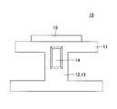
- FIG. 1 is a front view of the motion detection sensor 10 (only the covering member 17 is shown in cross section)
- FIG. 2 is a side view of the motion detection sensor 10 (illustration of the covering member 17 is omitted)
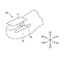
- FIG. 4 is a perspective view showing a state where the motion detection sensor 10 is attached to a finger A.
- the motion detection sensor 10 has a function of detecting a motion of the finger A, which is a test subject, using a finger A of a person (subject) as a test subject as shown in FIG.
- the motion detection sensor 10 generally includes a base portion 11, arm portions 12 and 13, a strain gauge 14, an acceleration sensor 15, a covering member 17, and the like.
- the base part 11 and the arm parts 12 and 13 serving as the base part are each composed of a plate-like member made of metal.
- the base part 11 and the arms 12 and 13 are made of different metal materials.
- the base part 11 is made of an aluminum plate
- the arm parts 12 and 13 are made of a springy material (for example, stainless steel) that is more easily elastically deformed than the base part 11. Therefore, the arms 12 and 13 are configured to be elastically deformable in the directions of arrows B1 and B2 in FIG.
- the arm portions 12 and 13 are joined to the base portion 11 by welding.
- a fixing member such as a screw is used.
- the arm portions 12 and 13 are easily elastically deformed with respect to the base portion 11. It is also possible to form it integrally.
- the arm portions 12 and 13 are configured to extend downward (in the direction of arrow Z1 in the drawing) from both side edges of the base portion 11 in the direction of arrows X1 and X2 in the drawing. That is, the arm portions 12 and 13 are in a cantilever shape in which one end is fixed to the base portion 11 and the other end portion is a free end.
- the motion detection sensor 10 is attached to the finger A, as shown in FIGS. 1 and 3, the base portion 11 comes into contact with the upper portion of the finger A (upper portion of the nail), and the pair of arm portions 12 and 13 are It abuts on both sides of the finger A. In this mounted state, the pair of arm portions 12 and 13 are slightly elastically deformed in the B1 direction. For this reason, the finger A is held between the pair of arm portions 12 and 13 by this elastic force. The motion detection sensor 10 is attached to the finger A by this clamping force.
- the acceleration sensor 15 is disposed on the upper part of the base part 11.
- the acceleration sensor 15 detects the acceleration of the finger A when the finger A moves.
- a triaxial acceleration sensor is used as the acceleration sensor 15. Therefore, when the finger A moves, the motion detection sensor 10 is configured to detect each acceleration in the X1, X2 direction, the Y1, Y2 direction (see FIG. 3), and the Z1, Z2 directions orthogonal to each other.
- the acceleration sensor 15 used in the motion detection sensor 10 according to the present embodiment has a detectable speed range of 25 mm / s or more, a measurable speed range of 50 mm / s or more, and a measurable acceleration range of 2,4. 8G can be used.
- the strain gauge 14 is disposed in the arm portions 12 and 13 and measures strain generated in the arm portions 12 and 13 when the finger A moves. As shown in FIG. 4, the strain gauge 14 is configured such that a resistor 14a is formed in a predetermined pattern (for example, a meander pattern) on a film-like base material 14b. Moreover, the wiring 14c is connected to the both ends of the resistor 14a.
- a resistor 14a is formed in a predetermined pattern (for example, a meander pattern) on a film-like base material 14b.
- the wiring 14c is connected to the both ends of the resistor 14a.
- the resistor 14a has a characteristic of changing the electric resistance by being deformed. That is, as shown in FIG. 5, the resistor 14a has a characteristic that its resistance value increases as the amount of deformation increases. Therefore, the strain can be measured by measuring the resistance change of the resistor 14a output from the wiring 14c as a voltage change.
- a single strain gauge 14 has a small resistance change due to strain.
- the two strain gauges 14 are disposed on the arm portion 12 and the two strain gauges 14 are disposed on the arm portion 13 and assembled into a Wheatstone bridge circuit. The measurement accuracy is improved.
- the position where the strain gauge 14 is disposed on the arm portions 12 and 13 is set slightly above the position where the finger A contacts the arm portions 12 and 13 when the motion detection sensor 10 is attached to the finger A. ing. This is because when the strain gauge 14 is positioned below the arm portions 12 and 13 (in the Z1 direction), it cannot contact the finger A to perform proper strain detection, and conversely, the strain gauge 14 is close to the base portion 11 ( This is because the displacement amount of the arm portions 12 and 13 is reduced and the proper strain cannot be detected.
- the covering member 17 is a resin material, and is formed on the upper portion of the base portion 11 so as to cover the acceleration sensor 15. As described above, the motion detection sensor 10 is attached to the finger A. Further, when measuring the motion of the finger A using the motion detection sensor 10, for example, when trying to measure a makeup motion using cosmetics, the cosmetics adhere to the fingers A.
- the acceleration sensor 15 is covered with the covering member 17 so that cosmetics or the like (hereinafter referred to as “attachments”) do not affect the acceleration sensor 15.
- each strain gauge 14 may be provided on the surface of each strain gauge 14 to protect each strain gauge 14. It should be noted that the covering member 17 is not necessarily required when no deposit is used when the motion detection sensor 10 is used.
- the motion detection sensor 10 has a very simple configuration in which the strain gauge 14 and the acceleration sensor 15 are disposed on the base portion 11 and the arm portions 12 and 13 made of a thin plate metal material. ing.
- the strain gauge 14 is thin and lightweight because the resistor 14a is formed on the film-like base material 14b as described above.
- the motion detection sensor 10 according to the present embodiment can be reduced in size and weight.
- the motion detection sensor 10 according to the present embodiment has a length (dimensions in the directions of arrows Y1 and Y2 in the drawing) of 8 mm and a height (dimensions in the directions of arrows Z1 and Z2 in the drawing) of 3.5 mm.
- the weight could be 2.4g. Thereby, the usability of the motion detection sensor 10 can be improved.
- it since it is lightweight, it can prevent that the own weight of the motion detection sensor 10 influences acceleration measurement.
- the inventor conducted an experiment to examine the relationship between the contact force of the finger A and the deformation of the finger side surface.
- a finger A without a jig is pressed against the pressing plate 16 (the force applied to the finger A at this time is referred to as finger contact force).
- the deformation of the finger side surface occurring in A was measured from the direction indicated by arrow X in the figure.
- the deformation of the finger side surface is defined as the deformation of the finger A in the directions of arrows X1 and X2 (horizontal direction) in the drawing.
- the deformation of the finger side surface was measured using a laser displacement meter. Since the laser displacement meter can measure the deformation of the finger A without contacting the finger A, the accuracy of the experiment can be improved.
- the finger A with the jig 18 attached is pressed against the pressing plate 16, and the deformation of the finger side surface that occurs on the finger A at this time is measured from the X direction using a laser displacement meter. Measured.
- the jig 18 a configuration in which the strain gauge 14, the acceleration sensor 15, and the covering member 17 are removed from the motion detection sensor 10 described above is used.
- FIG. 7 is a diagram showing the relationship between the finger contact force and the deformation of the finger side surface obtained by the above experiment.
- the characteristic indicated by the arrow A is a characteristic when the jig 18 shown in FIG. 6A is not attached
- the characteristic indicated by the arrow B is the characteristic when the jig 18 shown in FIG. 6B is attached.
- the case characteristics In either case, the experiment is performed once, and the measurement results are shown.
- the motion detection sensor 10 uses this experimental result as a measurement principle.
- the motion detection sensor 10 when deformation occurs on the finger side surface of the finger, distortion occurs in the arm portions 12 and 13 holding the finger. Is detected by the strain gauge 14, and the deformation of the finger side surface of the finger is measured.
- the upper dish balance 25 has a dish 26 and a dish 27.
- a weight 29 is placed on the plate 26. As the weight 29, eight kinds of weights having different weights for every 100 g weight of 100 g weight to 800 g weight were prepared.
- the lower contactor 20 is disposed on the plate 27.
- the lower contactor 20 is in contact with a finger, and the area of the upper surface of the lower contactor 20 is sufficiently large to cover the fingertip of the finger (for example, 25 mm ⁇ ).
- an upper contactor 19 is disposed at an upper position facing the lower contactor 20. Further, the deformation of the finger side surface of the finger was measured using a laser displacement meter, which is a non-contact sensor, as described with reference to FIG.
- the weight of the lower contactor 20 is corrected in advance, and the plate 27 provided with the plate 26 and the lower contactor 20 is set so as to maintain a balance in a state where the weight 29 is not placed on the plate 26.
- Measurement was performed on the finger in the wearing state with the jig 18 attached.
- a finger in a mounted state was fixed to the upper contactor 19 with a double-sided tape, and a weight 29 was placed on the dish 26 in this state.
- the plate 27 moves in the direction of arrow D, and the lower contactor 20 contacts the finger and presses the finger. Since the finger is fixed to the upper contactor 19, the force with which the lower contactor 20 presses the finger becomes the finger contact force.
- This finger contact force is variable depending on the weight of the weight 29 placed on the plate 26.
- the eight types of weights 29 are prepared. Therefore, a finger contact force of 100 to 800 g weight can be applied to the finger. And the deformation
- a plurality of jigs 18 were prepared in which the thickness of the base portion 11 was constant and the thickness of the arm portions 12 and 13 was changed.
- a jig 18 having arm portions 12 and 13 having four types of thicknesses of 0.1 mm, 0.2 mm, 0.3 mm, and 0.5 mm is manufactured, and each of them is attached to a finger, and the finger side surface of the finger is attached. An experiment was conducted to measure the deformation.
- FIG. 9 shows the experimental results of this experiment.
- the arrow A indicates the finger side surface deformation characteristics when the jig 18 having the arm portions 12 and 13 having a thickness of 0.1 mm is mounted
- the arrow B indicates the arm portions 12 and 13 having a thickness of 0.2 mm.
- the finger side surface deformation characteristics when the jig 18 is mounted are shown
- the arrow C indicates the finger side surface deformation characteristics when the jig 18 having the arm portions 12 and 13 having a thickness of 0.3 mm is mounted.
- An arrow D indicates the finger side surface deformation characteristics when the jig 18 having the arm portions 12 and 13 having a thickness of 0.5 mm is attached.
- the thickness of the arm portions 12 and 13 is set to a value of 0.2 mm or more and 0.5 mm or less. Thereby, the motion detection accuracy of the motion detection sensor 10 can be improved.
- toe is required.
- this preload can be easily set large. Further, as described above, when the thickness of the arm portions 12 and 13 is increased, the linearity and the repeatability are improved.
- the preload that is the force for pinching the finger can be maintained constant.
- individual differences in finger side deformation at the time of wearing can be reduced, and thus the standard error of finger deformation can be reduced.
- the mounting property of the arm portions 12 and 13 on the finger is improved, and the measurement accuracy can be improved.
- the motion detection sensor 10 can be securely worn on the finger, and the motion detection sensor 10 can be prevented from being detached from the finger when motion is detected.
- FIG. 10 shows the pressure sensor 28 used for calibration.
- This pressure sensor 28 has a structure in which a support 36A is erected on a base 35A, and a contact portion 34A is provided at the upper end of the support 36A.
- the pressure sensor 28 is provided with a three-component load cell 31 so that the load applied to the contact portion 34A can be measured.
- the motion detection sensor 10 is attached to the finger A as shown in FIG. 10, and then the contact portion 34A of the pressure sensor 28 is pressed.
- the strain amount of the arm portions 12 and 13 (corresponding to the amount of deformation of the finger side surface of the finger A) is measured from the strain gauge 14 of the motion detection sensor 10, and the contact portion 34A from the three component force load cell 31.
- the finger contact force of the finger A with respect to is required. This process is performed with various finger contact forces by changing the finger contact force of the finger A with respect to the contact portion 34A.
- the strain amount data obtained from the strain gauge 14 thus obtained and the finger contact force data obtained from the vector combined load of the three-component force load cell 31 are approximated by, for example, polynomial approximation (quadratic function) based on the least square method. Is done.
- FIG. 11 shows the relationship between the amount of distortion of the arm portions 12 and 13 and the finger contact force (hereinafter referred to as calibration characteristics) obtained in this way. Therefore, by using this calibration characteristic, the motion detection sensor 10 can obtain the finger contact pressure (load) applied to the finger A based on the strain amount data output from the strain gauge 14. .
- the calibration performed as described above is a calibration process including the inherent deformation characteristics and attributes of the finger A of the subject wearing the motion detection sensor 10. For this reason, the detection accuracy by the motion detection sensor 10 can be improved by obtaining the finger contact pressure from the strain amount data based on the calibration characteristics.
- a calibration characteristic that most closely approximates the characteristics of the subject is extracted from a plurality of types of calibration processing. Calibration can also be performed based on this. In this case, the process for obtaining the calibration characteristics described above for each subject can be eliminated, and the motion detection of the finger A can be easily performed.
- FIG. 12 shows an apparatus used for calibration evaluation.
- This device includes a vibration device 30 and an upper contactor 32. Further, the vibration device 30 has an output shaft 36B that vibrates in the vertical direction in the figure (the arrow Z direction in the figure). A lower contactor 34B for pressing the finger A is provided at the tip of the output shaft 36B. Further, a three-component force load cell 31 capable of measuring a load applied to the lower contactor 34B is disposed in the middle of the output shaft 36B.
- the upper contactor 32 is disposed at a position facing the lower contactor 34B. Therefore, an alternating load can be applied to the finger A by holding the finger A between the upper contactor 32 and the lower contactor 34B and driving the vibration device 30.
- the finger A wearing the motion detection sensor 10 is sandwiched between the upper contactor 32 and the lower contactor 34B, and vibration that is displaced in the Z direction by the vibration device 30 is applied to the output shaft 36B. Further, the vibration at this time was 0.5 Hz, and the time for applying the vibration (experiment time) was 60 seconds.
- a pressing force (equivalent to finger contact pressure; hereinafter referred to as finger contact pressure) is alternately applied from the vibration device 30 to the finger A.
- finger contact pressure is measured using the motion detection sensor 10 and the two sensors of the three component load cell 31.
- the motion detection sensor 10 deforms the finger A when a pressing force is applied, and measures the amount of strain generated in the arm portions 12 and 13 with the strain gauge 14 along with this, and described above for the strain amount data. Calibration is performed, and the finger contact pressure generated on the finger A is calculated from the calibration.
- the output value of the three-component force load cell 31 is directly used as the finger contact pressure. Therefore, when the value of the finger contact pressure obtained from the measurement result of the motion detection sensor 10 matches the measurement result of the three-component force load cell 31 as described above, the calibration has high accuracy. Can be evaluated.
- FIG. 13 shows the experimental results of the above experiment.
- the horizontal axis represents time
- the vertical axis represents the measured value of finger contact pressure.
- an arrow A indicates a measurement result (comparison value) by the load cell 31.
- the arrow B in the figure indicates the motion detection sensor 10 after approximating the relationship of (finger) strain [ ⁇ ] ⁇ finger contact pressure [N] obtained in FIG. It is the result of estimating the contact force from the measurement result of (strain gauge 14) (actual measurement value 1).
- an arrow C in the figure indicates a value (actual value 2) obtained by approximating the measurement result of the motion detection sensor 10 (strain gauge 14) using a reference table.
- the motion detection sensor 10 can measure the finger contact pressure during the movement of the finger A with the strain gauge 14, and can measure the speed of the finger A during the movement of the finger A with the acceleration sensor 15. it can.
- FIG. 14 shows each output when the subject performs each operation of applying lipstick to the lower lip and then applying lipstick to the upper lip from the operation of opening the cap of the lipstick container.
- the horizontal axis indicates time
- the vertical axis indicates finger contact pressure and finger motion acceleration.
- the acceleration is shown as an absolute value.
- the strain gauge 14 does not react until the cap of the lipstick container is opened, but the acceleration sensor 15 detects the movement of the finger A. It was also found that when the subject opens the cap of the lipstick container, both the finger contact force and the finger motion acceleration increase rapidly. Furthermore, it was found that when the lipstick is applied to the upper lip or the lower lip, both the finger contact force and the finger motion acceleration change more slowly than when the cap is opened.
- the motion detection sensor 10 can simultaneously measure the finger contact force and the finger motion acceleration. Therefore, it can be expected to use the motion detection sensor 10 to evaluate the ease of use of cosmetics and to evaluate the characteristics (smoothness, viscosity, etc.) of the cosmetic preparation itself.
- the motion detection sensor 10 is used for detection of a cosmetic application operation.
- the application of the motion detection sensor 10 is not limited to this, and in various technical fields. It can be used.
- the base portion 11 and the arm portions 12 and 13 are both made of metal.
- the base portion 11 and the arm portions 12 and 13 are not necessarily limited to metal, such as resin. It is also possible to configure by.
Landscapes
- Physics & Mathematics (AREA)
- General Physics & Mathematics (AREA)
- Measurement Of The Respiration, Hearing Ability, Form, And Blood Characteristics Of Living Organisms (AREA)
- Position Input By Displaying (AREA)
- User Interface Of Digital Computer (AREA)
Abstract
本発明は指に装着してその動作を検出する動作検出センサに係り、装着状態で前記指の上部に位置する基部と、該基部の両側部から前記指の側部に延出され装着状態において指を挟持する一対のアームと、前記基部に配設されており前記指が動作した時の該指の加速度検出を行う加速度センサと、前記アームに配設されており前記指が動作した時に該指の変形に伴い前記アームに発生する歪を測定する歪ゲージとを備える。
Description
本発明は動作検出センサに係り、特に指に装着してその動作を検出する動作検出センサに関する。
一般に、化粧を行う場合には種々の化粧品や化粧道具を用いる。化粧品の中には、化粧を行う施術者が化粧品を直接把持して化粧を行うものがある(例えば、マスカラ,アイライナー等)。また化粧を行うに際し、施術者が化粧道具(リップブラシやチークブラシ等の各種ブラシ、メーキャップパフ、ファンデーションスポンジ、コットン等)を用いる場合もある。
このように化粧を行う場合、施術者は化粧品や化粧道具(以下、総称して化粧道具等という)を手にとって使用することになる。従って化粧道具等は、施術者が直接把持した際の使用感を向上させることが重要となる。また、使用性の向上を客観的に判断できるように、化粧道具等の使用感は定量的に検出できることが望ましい。
この化粧道具等の使用感を定量的に検出するには、化粧を行う際の指先の動作と、その動作を行った時に指先に感じる感触を検出することが必要となる。指先に感じる感触は、被験者(化粧道具等を使用する者)に対して官能検査を行うことにより得ることができる。これに対して指先の動作は、特許文献1に開示されているような動作検出センサを用いて検出することが可能である。この特許文献1に開示されたセンサでは、指の爪に歪みセンサを配置し、指の動作時に爪に発生する歪みを検出することにより指先の動作を検知する構成とされている。
しかしながら、特許文献1に開示された発明は、爪に直接センサを接着剤等を用いて貼着する構成であったため、取り扱いが不便であるという問題点があった。また、爪の大きさや剛性には個人差があり、被験者の爪の個人特性により検出結果が左右されるという問題点があった。
更に、強い動作を行う場合には爪の歪みが確実に発生するため精度の高い動作検出が行えるが、化粧道具等を使用する時のような、あまり大きな力を必要としない動作の場合には爪に発生する歪が小さく、高精度の動作検出が行えないという問題点があった。
本発明は、上述した従来技術の問題を解決する、改良された有用な動作検出センサを提供することを総括的な目的とする。
本発明のより詳細な目的は、指の動作を高精度に検出しうる動作検出センサを提供することにある。
この目的を達成するために、本発明は、
指に装着され、該指の動作を検出する動作検出センサであって、
装着状態で前記指の上部に位置する基部と、
前記基部の両側部から前記指の側部に延出され、装着状態において指を挟持する一対のアームと、
該基部に配設されており、前記指が動作した時の該指の加速度検出を行う加速度センサと、
前記アームに配設されており、前記指が動作した時に該指の変形に伴い前記アームに発生する歪を測定する歪ゲージとを有することを特徴とするものである。
指に装着され、該指の動作を検出する動作検出センサであって、
装着状態で前記指の上部に位置する基部と、
前記基部の両側部から前記指の側部に延出され、装着状態において指を挟持する一対のアームと、
該基部に配設されており、前記指が動作した時の該指の加速度検出を行う加速度センサと、
前記アームに配設されており、前記指が動作した時に該指の変形に伴い前記アームに発生する歪を測定する歪ゲージとを有することを特徴とするものである。
開示の動作検出センサによれば、加速度センサにより指の動作を直接的に検出することができ、また歪ゲージによりアームを介して指の変形を検出することができる。指の変形は指で感じる感性と関係があるため、開示の動作検出センサを用いることにより、指の動作測定と指による感性評価を同時に行うことで包括的な感性評価が可能になる。
10 動作検出センサ
11 ベース部
12,13 アーム部
14 歪ゲージ
15 加速度センサ
18 治具
25 上皿天秤
28 圧力センサ
30 振動装置
31 3分力ロードセル
11 ベース部
12,13 アーム部
14 歪ゲージ
15 加速度センサ
18 治具
25 上皿天秤
28 圧力センサ
30 振動装置
31 3分力ロードセル
以下、本発明の実施形態について図面を参照しつつ説明する。
図1乃至図3は、本発明の一実施形態である動作検出センサを示している。図1は動作検出センサ10の正面図(被覆部材17のみ断面で示す)であり、図2は動作検出センサ10の側面図(被覆部材17の図示は省略している)であり、図3は動作検出センサ10を指Aに装着した状態を示す斜視図である。
本実施形態に係る動作検出センサ10は、図3に示すように人(被験者)の指Aを被検査体とし、この被検査体である指Aの動作を検出する機能を奏するものである。この動作検出センサ10は、大略するとベース部11、アーム部12,13、歪ゲージ14、加速度センサ15、及び被覆部材17等を有した構成とされている。
基部となるベース部11及びアーム部12,13は、いずれも金属よりなる板状の部材で構成されている。ベース部11とアーム12,13は、異なる金属材料とされている。具体的には、ベース部11はアルミニウム板により構成されており、またアーム部12,13はベース部11よりも弾性変形し易いバネ性を有する材料(例えば、ステンレス鋼)により構成されている。よって、アーム12,13は、ベース部11に対して図1に矢印B1,B2方向に弾性変形可能な構成とされている。
なお本実施形態では、アーム部12,13は、溶接によりベース部11に接合された構成とされている。しかしながら、ネジ等の固定部材を用いて接合した構成とすることも可能である。また、ベース部11とアーム部12,13の厚さを変えることにより、ベース部11に対してアーム部12,13を弾性変形し易くすること等により、ベース部11とアーム部12,13を一体的に形成することも可能である。
アーム部12,13は、ベース部11の図中矢印X1,X2方向の両側縁部から下方(図中矢印Z1方向)に延出した構成とされている。即ち、アーム部12,13は、一端がベース部11に固定されると共に他端部が自由端とされた片持ち梁状とされている。
よって、動作検出センサ10を指Aに装着した際、図1及び図3に示すように、ベース部11は指Aの上部(爪の上部)に当接し、また一対のアーム部12,13は指Aの両側部に当接する。この装着状態において、一対のアーム部12,13はB1方向に若干弾性変形する。このため、この弾性力により指Aは一対のアーム部12,13に挟持された状態となる。この挟持力により、動作検出センサ10は指Aに装着される。
加速度センサ15は、ベース部11の上部に配設されている。この加速度センサ15は、指Aが動作した際、この指Aの加速度を検出する。本実施形態では、加速度センサ15として、3軸加速度センサを用いている。よって指Aが動作する際、動作検出センサ10は互いに直行するX1,X2方向、Y1,Y2方向(図3参照)、及びZ1,Z2方向に対する各加速度を検出しうる構成となっている。
なお、本実施形態に係る動作検出センサ10に用いる加速度センサ15としては、検出可能な速度レンジが25mm/s以上、計測可能な速度レンジが50mm/s以上、計測可能な加速度レンジが2,4,8Gのものを用いることができる。
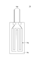
歪ゲージ14はアーム部12,13に配設されており、指Aが動作した際にアーム部12,13に発生する歪を測定するものである。この歪ゲージ14は、図4に示すようにフィルム状のベース材14bに所定のパターン(例えば、ミアンダ状パターン)で抵抗体14aが形成された構成とされている。また、抵抗体14aの両端部には配線14cが接続されている。
抵抗体14aは、変形することにより電気抵抗を変化する特性を有している。即ち、図5に示すように抵抗体14aは変形量が増大することにより、その抵抗値が増大する特性を有している。よって、配線14cから出力される抵抗体14aの抵抗変化を電圧変化として測定することにより歪を測定することが可能となる。
しかしながら、1個の歪ゲージ14では歪による抵抗変化が小さい。このため、本実施形態では、アーム部12に2個の歪ゲージ14を配設すると共に、アーム部13にも2個の歪ゲージ14を配設し、これをホイートストンブリッジ回路に組むことにより、測定精度の向上を図っている。
なお、歪ゲージ14のアーム部12,13への配設位置は、動作検出センサ10を指Aに装着した際、指Aがアーム部12,13と当接する位置よりも若干上部位置に設定されている。これは、歪ゲージ14がアーム部12,13の下方(Z1方向)位置すると指Aに接触して適正な歪検出を行うことができず、逆に歪ゲージ14がベース部11に近い上方(Z2方向)位置するとアーム部12,13の変位量が少なくなりやはり適正な歪検出を行うことができないためである。
被覆部材17は樹脂材であり、ベース部11の上部に加速度センサ15を被覆するよう形成されている。前記のように、動作検出センサ10は指Aに装着される。また、動作検出センサ10を用いて指Aの動作測定を行う際、例えば化粧料を用いた化粧動作を測定しようとした場合、指Aに化粧料が付着する。
よって、ベース部11上に加速度センサ15が露出した状態では、化粧料が加速度センサ15にも付着して加速度センサ15を劣化させる可能性がある。そこで本実施形態では、化粧料等(以下、付着物という)が加速度センサ15に影響を及ぼさないよう、加速度センサ15を被覆部材17で被覆した構成としている。
また、同様の理由により、各歪ゲージ14の表面に被覆部材を設け、各歪ゲージ14を保護する構成としてもよい。なお、動作検出センサ10の使用に際して付着物を用いない場合には、被覆部材17は必ずしも必要ではない。
上記構成とされた本実施形態に係る動作検出センサ10は、薄板状の金属材よりなるベース部11及びアーム部12,13に歪ゲージ14及び加速度センサ15を配設した極めて簡単な構成とされている。また、歪ゲージ14は、前記のようにフィルム状のベース材14bに抵抗体14aが形成された構成であるため、薄くまた軽量なものである。
このため、本実施形態に係る動作検出センサ10は、小型化及び軽量化を図ることができた。具体的には、本実施形態に係る動作検出センサ10は、長さ(図中、矢印Y1,Y2方向の寸法)を8mm、高さ(図中、矢印Z1,Z2方向の寸法)を3.5mm、重さを2.4g重とすることができた。これにより、動作検出センサ10の使用性の向上を図ることができる。また、軽量であるため、動作検出センサ10の自重が加速度計測に影響を及ぼすことを防止することができる。
次に、上記構成とされた動作検出センサ10の動作原理について説明する。
本発明者は指Aの接触力と指側面の変形との関係を調べる実験を行った。本実験では、先ず、図6(A)に示すように治具を非装着の指Aを押圧板16に押圧し(この時に指Aに印加される力を指接触力という)、この時に指Aに発生する指側面の変形を図中矢印Xで示す方向から測定した。ここで、指側面の変形とは、図中矢印X1,X2方向(水平方向)への指Aの変形であると定義する。
本実験では、この指側面の変形をレーザ変位計を用いて測定した。レーザ変位計は、指Aに非接触で指Aの変形測定を行うことができるため、実験の精度を高めることができる。
次に、図6(B)に示すように治具18を装着した状態の指Aを押圧板16に押圧し、この時に指Aに発生する指側面の変形をX方向からレーザ変位計を用いて測定した。また、治具18としては、前記した動作検出センサ10において、歪ゲージ14、加速度センサ15、及び被覆部材17を取り外した構成のものを使用した。
図7は、上記の実験により得られた指接触力と指側面の変形との関係とを示す図である。同図中、矢印Aで示す特性は図6(A)に示した治具18を装着しない場合の特性であり、矢印Bで示す特性は図6(B)に示した治具18を装着した場合の特性である。いずれの場合も1回ずつ実験を行い、その際の測定結果を示している。
同図に示されるように、治具18を装着しない場合には、指接触力の増加に伴い、指側面の変形は飽和する傾向を示すことが判った。これに対して、治具18を装着し指Aを治具18で挟み込んだ場合には、指接触力の増加に伴い、指側面の変形も線形に増加する傾向を示すことが判った。
上記の実験結果より、治具18を装着した場合には指接触力の変化と指側面の変形に線形的な相関があり、よって指側面の変形を測定することにより、指Aに印加されている指接触力を求めることができることが判った。本実施形態に係る動作検出センサ10は、この実験結果を測定原理としている。
次に、本発明者が実施した、動作検出センサ10を構成するアーム部12,13の厚さの適正値を求める実験について説明する。本実施形態に係る動作検出センサ10は、指の指側面に変形が発生した場合、指を挟持しているアーム部12,13に歪が発生するため、このアーム部12,13に発生する歪を歪ゲージ14で検出することにより指の指側面の変形を測定する構成としている。
このため、アーム部12,13が指の変形に追随して変形して歪を発生しないと、動作検出センサ10の測定精度が低下してしまう。そこで、図8に示す上皿天秤25を用いて、アーム部12,13の厚さの適正値を求める実験を行った。
上皿天秤25は、皿26と皿27を有している。皿26には錘29が乗せられる。錘29としては、100g重~800g重の100g重毎に重さの異なる8種類の錘を用意した。
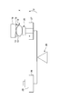
また、皿27には下部コンタクタ20を配設した。この下部コンタクタ20は、指が接触するものであり、その上面の面積は指の指先を十分にカバーする大きさ(例えば、25mmφ)とされている。また、下部コンタクタ20と対向する上部位置には、上部コンタクタ19を配設した。更に、指の指側面の変形は、図6で説明したと同様に、非接触センサであるレーザ変位計を用いて測定した。
なお、予め下部コンタクタ20の重さは補正されており、皿26に錘29を乗せない状態において、皿26と下部コンタクタ20が設けられた皿27は、均衡を保つように設定されている。
測定は、治具18を装着した装着状態の指に対して実施した。また、測定方法としては、装着状態の指を両面テープにより上部コンタクタ19に固定し、この状態で皿26に錘29を乗せた。これにより、皿27は矢印D方向に移動し、下部コンタクタ20は指に接触し、指を押圧する。指は上部コンタクタ19に固定されているため、下部コンタクタ20が指を押圧する力が指接触力となる。
この指接触力は、皿26に乗せる錘29の重さにより可変される。本実施形態では、上記の8種類の錘29を用意している。このため、100g重~800g重の指接触力を指に対して印加することができる。そして、それぞれの指接触力における指の指側面の変形をレーザ変位計により測定した。
また、指に装着する治具18としては、ベース部11の厚さは一定とし、アーム部12,13の厚さを変えた複数の治具18を用意した。本実施形態では、0.1mm,0.2mm,0.3mm,0.5mmの4種類の厚さのアーム部12,13を有した治具18を作製し、それぞれを指に装着して指の指側面の変形を測定する実験を行った。
図9は、この実験の実験結果を示している。図中、矢印Aは厚さ0.1mmのアーム部12,13を有した治具18を装着した時の指の指側面変形特性を示し、矢印Bは厚さ0.2mmのアーム部12,13を有した治具18を装着した時の指の指側面変形特性を示し、矢印Cは厚さ0.3mmのアーム部12,13を有した治具18を装着した時の指の指側面変形特性を示し、矢印Dは厚さ0.5mmのアーム部12,13を有した治具18を装着した時の指の指側面変形特性を示している。
同図に矢印Aで示すように、厚さが0.1mmと薄いアーム部12,13の治具18では、指変形が緩やかであることが判る。しかしながら、アーム部12,13が薄いと線形性や繰り返し精度が低下し、よって動作検出センサ10の動作検出精度が低下してしまうおそれがある。
これに対し、図中矢印B~Dで示す厚さが0.2m~0.5mmのアーム部12,13である治具18を用いた場合には、標準誤差も小さく、線形性や繰り返し精度を高く維持することができる。以上の実験結果より、本実施形態に係る動作検出センサ10では、アーム部12,13の厚さを0.2mm以上0.5mm以下の値に設定した。これにより、動作検出センサ10の動作検出精度の向上を図ることができる。
なお、上記のように動作検出センサ10を指に装着する際、アーム部12,13が指を挟持する力(予圧)が必要となる。アーム部12,13の厚さを大きくした場合には、この予圧を容易に大きく設定することができる。かつ、アーム部12,13の厚さを大きくした場合には、線形性や繰り返し精度を向上させることは前述したとおりである。
更に、本実施形態のようにアーム部12,13の厚さを0.2mm以上0.5mm以下に設定した場合、指を挟持する力である予圧を一定に維持することができる。加えて、被験者の指の大きさに差異があっても、装着時における指側面の変形の個人差を小さくすることができ、よって指変形の標準誤差を小さくすることができる。
これにより、アーム部12,13の指に対する装着性が高まり、測定精度の向上を図ることができる。同時に、誰が動作検出センサ10を装着しても指へ確実に装着することが可能となり、動作検出時に動作検出センサ10が指から離脱することを防止することができる。
ところで、動作検出センサ10を用いて指Aの動作検出を高精度に行おうとした場合、動作検出センサ10により検出される指Aの指側面の変形量と指接触力の値とが高精度に相関している必要がある。また、動作検出センサ10を装着する被験者により、指Aの大きさや変形量等に個人差が存在する。そこで、動作検出センサ10による指Aの動作検出処理に先立ち、指Aの指側面の変形量と指接触力の値とを相関させる校正処理(キャリブレーション)を行う必要がある。以下、本実施形態における、動作検出センサ10のキャリブレーション(校正処理)について説明する。
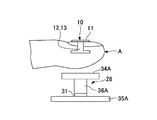
図10及び図11は、キャリブレーションを説明するための図である。図10は、キャリブレーションに用いる圧力センサ28を示している。この圧力センサ28は、ベース35A上に支柱36Aが立設され、この支柱36Aの上端部にコンタクト部34Aが設けられた構成とされている。また、圧力センサ28には3分力ロードセル31が配設されており、コンタクト部34Aに印加された荷重を測定できる構成とされている。
キャリブレーションにおいては、先ず図10に示すように指Aに動作検出センサ10を装着した上で、圧力センサ28のコンタクト部34Aを押圧する。この時、動作検出センサ10の歪ゲージ14からはアーム部12,13の歪量(指Aの指側面の変形量に対応する)が測定されると共に、3分力ロードセル31からはコンタクト部34Aに対する指Aの指接触力が求められる。この処理を、指Aのコンタクト部34Aに対する指接触力を変化させることにより、種々の指接触力で実施する。
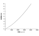
このように求められた歪ゲージ14からの歪量データと、3分力ロードセル31のベクトル合成荷重から求められた指接触力データは、例えば最小2乗法に基づき多項式近似(二次関数)で近似される。図11は、このようにして求められた、アーム部12,13の歪量と指接触力との関係(以下、キャリブレーション特性という)を示している。よって、このキャリブレーション特性を用いることにより、動作検出センサ10は歪ゲージ14からの出力される歪量データに基づき、指Aに印加されている指接触圧(荷重)を求めることが可能となる。
上記のように実施されるキャリブレーションは、動作検出センサ10を装着する被験者の指Aの固有の変形特性及び属性を含めた校正処理となる。このため、キャリブレーション特性に基づき歪量データから指接触圧を求めることにより、動作検出センサ10による検出精度を高めることができる。
また上記のキャリブレーション特性をプログラムとして図示しない動作検出装置(パーソナルコンピュータ等)に格納しておくことにより、複数種類の校正処理のうち被験者の特性に最も近似したキャリブレーション特性を抽出し、これに基づきキャリブレーションを行うことも可能となる。この場合、個々の被験者に対して上記したキャリブレーション特性を得るための処理を不要とすることができ、指Aの動作検出を容易に行うことが可能となる。
次に、本発明者が実施した上記したキャリブレーションを評価する実験について説明する。
図12は、キャリブレーションの評価に用いた装置を示している。この装置は、振動装置30と上部コンタクタ32とにより構成されている。また、振動装置30は、図中上下方向(図中、矢印Z方向)に振動する出力軸36Bを有している。この出力軸36Bの先端部には、指Aを押圧するための下部コンタクタ34Bが設けられている。更に、出力軸36Bの途中位置には、下部コンタクタ34Bに印加される荷重を測定できる3分力ロードセル31が配設されている。
上部コンタクタ32は、下部コンタクタ34Bと対向する位置に配設されている。よって、上部コンタクタ32と下部コンタクタ34Bとの間に指Aを挟持させ、振動装置30を駆動することにより指Aに対して交番的な荷重を印加することができる。
実験方法としては、上部コンタクタ32と下部コンタクタ34Bとの間で動作検出センサ10を装着した指Aを挟持させ、振動装置30により出力軸36BにZ方向に変位する振動を印加した。また、この時の振動は0.5Hzとし、また振動を与える時間(実験時間)は60秒とした。
このように振動装置30が振動発生することにより、振動装置30から指Aには交番的に押圧力(指接触圧と等価。以下、指接触圧という)が印加される。本実験では、この振動装置30から印加される指接触圧を動作検出センサ10と、3分力ロードセル31の二つのセンサを用いて測定している。
動作検出センサ10は、押圧力が印加されたことにより指Aが変形し、これに伴いアーム部12,13に発生した歪量を歪ゲージ14により測定し、この歪量データに対して前記したキャリブレーションを実施し、これより指Aに発生する指接触圧を演算する。
これに対し、振動装置30に配設された3分力ロードセル31による測定では、3分力ロードセル31の出力値がそのまま指接触圧となる。よって、上記のように動作検出センサ10の測定結果から得られた指接触圧の値が、3分力ロードセル31の測定結果と一致していた場合、上記のキャリブレーションは高い精度を有していると評価することができる。
図13は、上記の実験の実験結果を示している。同図において、横軸は時間であり、縦軸は指接触圧の測定値を示している。
また同図において、矢印Aで示すのはロードセル31による測定結果(比較値)である。これに対して図中矢印Bで示すのは、予め図11で得ていた(指の)歪量[με]-指接触圧[N]の関係を最小二乗線形近似した上で動作検出センサ10(歪ゲージ14)の測定結果から接触力を推定した結果である(実測値1)。また、図中矢印Cで示すのは、動作検出センサ10(歪ゲージ14)の測定結果を、参照テーブルを用いて近似した値(実測値2)である。
前記のように、振動装置30は一定の振動数で出力軸34を振動させるため、図示されるように一定の間隔で高い指接触圧が出力されているが、実測値1,2と比較値とは高い精度を持って一致している。よって本実験結果より、上記したキャリブレーションを実施することにより、動作検出センサ10による動作時において指Aに作用する指接触圧を高精度に測定できることが実証された。
次に、動作検出センサ10を用いて実際に指Aの動作を測定した実験結果について説明する。本実験では、動作検出センサ10を用いて化粧動作を測定する実験を実施した。具体的には、被験者に化粧品として口紅を使用してもらい、この時の指Aの動作を動作検出センサ10を用いて測定した。
本実施形態に係る動作検出センサ10は、歪ゲージ14により指Aの動作時における指接触圧を測定でき、また加速度センサ15により指Aの動作時における指Aの動作の速度を測定することができる。
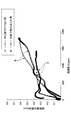
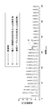
図14において、矢印Aで示すのは歪ゲージ14を介して測定された指接触圧であり、矢印Bで示すのは加速度センサ15を介して測定された指動作の加速度である。また、図14は、被験者が口紅容器のキャップを開く動作から下唇に口紅を塗布し、その後に上唇に口紅を塗布する各動作を行った時の各出力を示している。
なお、図14において横軸は時間を示し、縦軸は指接触圧及び指動作加速度を示している。また、加速度は絶対値として示している。
同図に示すように、歪ゲージ14は口紅容器のキャップを開くまでは反応しないが、加速度センサ15は指Aの動作を検出している。また、被験者が口紅容器のキャップを開く時は、指接触力及び指動作加速度共に急激に増加することが判った。更に、口紅を上唇或いは下唇に塗布する時においては、キャップ開蓋時に比べては指接触力及び指動作加速度共に緩やかな変化を行うことが判った。
このように、本実施形態に係る動作検出センサ10では、指接触力の測定と指動作加速度との測定を同時に行える。よって、動作検出センサ10を用いて化粧品の使用し易さを評価したり、また化粧品製剤自体の特性(滑らかさ,粘度等)を評価したりすることに利用することが望める。
以上、本発明の好ましい実施例について詳述したが、本発明は上記した特定の実施形態に限定されるものではなく、特許請求の範囲に記載された本発明の要旨の範囲内において、種々の変形・変更が可能なものである。
例えば、上記した実施形態では、動作検出センサ10を化粧料の塗布動作の検出に用いた例を示したが、動作検出センサ10の適用はこれに限定されるものではなく、種々の技術分野において利用が可能なものである。
また、本実施形態ではベース部11及びアーム部12,13をいずれも金属により構成した例を示したが、ベース部11及びアーム部12,13は必ずしも金属に限定されるものではなく、樹脂等により構成することも可能である。
本国際出願は2011年6月15日に出願された日本国特許出願2011-133395号に基づく優先権を主張するものであり、日本特許出願2011-133395号の全内容をここに本国際出願に援用する。
Claims (5)
- 指に装着され、該指の動作を検出する動作検出センサであって、
装着状態で前記指の上部に位置する基部と、
該基部の両側部から前記指の側部に延出され、装着状態において指を挟持する一対のアームと、
前記基部に配設されており、前記指が動作した時の該指の加速度検出を行う加速度センサと、
前記アームに配設されており、前記指が動作した時に該指の変形に伴い前記アームに発生する歪を測定する歪ゲージとを有することを特徴とする動作検出センサ。 - 前記加速度センサは、3軸加速度センサであることを特徴とする請求項1記載の動作検出センサ。
- 前記基部と前記アームを異なる材料とし、前記アームの材料を前記基部の材料に対して弾性変形し易い材料としたことを特徴とする請求項1記載の動作検出センサ。
- 前記アームの厚さを0.2mm以上0.5mm以下としたことを特徴とする請求項1記載の動作検出センサ。
- 前記アームは、一端が前記基部に固定されると共に他端部が自由端とされた片持ち梁状とされていることを特徴とする請求項1記載の動作検出センサ。
Applications Claiming Priority (2)
| Application Number | Priority Date | Filing Date | Title |
|---|---|---|---|
| JP2011133395A JP5809452B2 (ja) | 2011-06-15 | 2011-06-15 | 動作検出センサ |
| JP2011-133395 | 2011-06-15 |
Publications (1)
| Publication Number | Publication Date |
|---|---|
| WO2012173254A1 true WO2012173254A1 (ja) | 2012-12-20 |
Family
ID=47357232
Family Applications (1)
| Application Number | Title | Priority Date | Filing Date |
|---|---|---|---|
| PCT/JP2012/065425 Ceased WO2012173254A1 (ja) | 2011-06-15 | 2012-06-15 | 動作検出センサ |
Country Status (3)
| Country | Link |
|---|---|
| JP (1) | JP5809452B2 (ja) |
| TW (1) | TW201305855A (ja) |
| WO (1) | WO2012173254A1 (ja) |
Cited By (3)
| Publication number | Priority date | Publication date | Assignee | Title |
|---|---|---|---|---|
| JP2015117942A (ja) * | 2013-12-16 | 2015-06-25 | 国立大学法人 名古屋工業大学 | 爪振動計測装置、爪振動モニタリングシステムおよび爪振動フィードバック提示システム |
| US10342458B2 (en) | 2013-11-13 | 2019-07-09 | The University Of Western Ontario | Finger segment tracker and digitizer |
| JP2021060290A (ja) * | 2019-10-07 | 2021-04-15 | 株式会社 資生堂 | 動作計測装置、動作計測システム、及び動作計測方法 |
Families Citing this family (12)
| Publication number | Priority date | Publication date | Assignee | Title |
|---|---|---|---|---|
| JP6114562B2 (ja) * | 2013-01-22 | 2017-04-12 | 株式会社 資生堂 | 動作検出センサ及び動作検出装置 |
| JP6194550B2 (ja) * | 2013-04-26 | 2017-09-13 | 学校法人自治医科大学 | 手技シミュレータ |
| JP6546733B2 (ja) * | 2014-10-23 | 2019-07-17 | 智広 梅田 | 健康モニタシステム |
| KR101853706B1 (ko) * | 2016-11-30 | 2018-05-02 | (주)슈팅스 | 손가락 마디 간 착용형 반지 타입의 사용자 조작 센싱 장치 |
| KR102536546B1 (ko) * | 2017-06-29 | 2023-05-30 | 애플 인크. | 센서들 및 햅틱들을 갖는 핑거 장착형 디바이스 |
| US10712931B2 (en) | 2017-08-29 | 2020-07-14 | Apple Inc. | Systems for modifying finger sensations during finger press input events |
| WO2019159493A1 (ja) * | 2018-02-19 | 2019-08-22 | 株式会社資生堂 | 動作検出センサ及び動作検出方法 |
| JP7365136B2 (ja) * | 2018-05-17 | 2023-10-19 | 花王株式会社 | 触感評価方法および触感計測装置 |
| JP7198730B2 (ja) | 2019-07-05 | 2023-01-04 | 株式会社日立製作所 | センサデータ補正システム |
| US12229341B2 (en) | 2019-09-23 | 2025-02-18 | Apple Inc. | Finger-mounted input devices |
| JP7637375B2 (ja) * | 2020-12-03 | 2025-02-28 | 株式会社テック技販 | 触感検出装置 |
| JP2024033372A (ja) * | 2022-08-30 | 2024-03-13 | 株式会社 資生堂 | 蓋つき化粧料容器の開閉時の官能評価の結果の予測方法、予測装置及び予測プログラム、並びに蓋付き化粧料容器の設計方法及び製造方法 |
Citations (5)
| Publication number | Priority date | Publication date | Assignee | Title |
|---|---|---|---|---|
| JP2001265522A (ja) * | 2000-03-16 | 2001-09-28 | Keio Gijuku | 爪に装着するセンサ |
| JP2005349492A (ja) * | 2004-06-08 | 2005-12-22 | Sharp Corp | ロボットハンド |
| JP2006340370A (ja) * | 2006-05-05 | 2006-12-14 | Haruyuki Iwata | 指先装着センサによる入力装置 |
| JP2007236855A (ja) * | 2006-03-13 | 2007-09-20 | Sharp Corp | 光電式生体センサ |
| JP2009153550A (ja) * | 2007-12-25 | 2009-07-16 | Mitsuba Corp | 睡眠判定装置 |
Family Cites Families (6)
| Publication number | Priority date | Publication date | Assignee | Title |
|---|---|---|---|---|
| JP2001104256A (ja) * | 1999-10-04 | 2001-04-17 | Toriumu Kk | 指先接触圧センサー |
| JP2002007030A (ja) * | 2000-06-16 | 2002-01-11 | Olympus Optical Co Ltd | 運動検出装置及び操作入力装置 |
| JP4292247B2 (ja) * | 2003-11-20 | 2009-07-08 | 堅造 赤澤 | 動作解析装置およびその利用 |
| JP5108485B2 (ja) * | 2006-12-12 | 2012-12-26 | トヨタ自動車株式会社 | 触覚に作用する方法およびそれを実現する触覚デバイス、屈曲可変機構 |
| JP2009064053A (ja) * | 2007-09-04 | 2009-03-26 | Citizen Holdings Co Ltd | 操作入力装置 |
| JP2010277469A (ja) * | 2009-05-29 | 2010-12-09 | Brother Ind Ltd | 入力装置 |
-
2011
- 2011-06-15 JP JP2011133395A patent/JP5809452B2/ja active Active
-
2012
- 2012-06-15 WO PCT/JP2012/065425 patent/WO2012173254A1/ja not_active Ceased
- 2012-06-15 TW TW101121680A patent/TW201305855A/zh unknown
Patent Citations (5)
| Publication number | Priority date | Publication date | Assignee | Title |
|---|---|---|---|---|
| JP2001265522A (ja) * | 2000-03-16 | 2001-09-28 | Keio Gijuku | 爪に装着するセンサ |
| JP2005349492A (ja) * | 2004-06-08 | 2005-12-22 | Sharp Corp | ロボットハンド |
| JP2007236855A (ja) * | 2006-03-13 | 2007-09-20 | Sharp Corp | 光電式生体センサ |
| JP2006340370A (ja) * | 2006-05-05 | 2006-12-14 | Haruyuki Iwata | 指先装着センサによる入力装置 |
| JP2009153550A (ja) * | 2007-12-25 | 2009-07-16 | Mitsuba Corp | 睡眠判定装置 |
Cited By (5)
| Publication number | Priority date | Publication date | Assignee | Title |
|---|---|---|---|---|
| US10342458B2 (en) | 2013-11-13 | 2019-07-09 | The University Of Western Ontario | Finger segment tracker and digitizer |
| US11589779B2 (en) | 2013-11-13 | 2023-02-28 | Louis FERREIRA | Finger segment tracker and digitizer |
| JP2015117942A (ja) * | 2013-12-16 | 2015-06-25 | 国立大学法人 名古屋工業大学 | 爪振動計測装置、爪振動モニタリングシステムおよび爪振動フィードバック提示システム |
| JP2021060290A (ja) * | 2019-10-07 | 2021-04-15 | 株式会社 資生堂 | 動作計測装置、動作計測システム、及び動作計測方法 |
| JP7654355B2 (ja) | 2019-10-07 | 2025-04-01 | 株式会社 資生堂 | 動作計測装置、動作計測システム、及び動作計測方法 |
Also Published As
| Publication number | Publication date |
|---|---|
| TW201305855A (zh) | 2013-02-01 |
| JP5809452B2 (ja) | 2015-11-10 |
| JP2013003782A (ja) | 2013-01-07 |
Similar Documents
| Publication | Publication Date | Title |
|---|---|---|
| JP5809452B2 (ja) | 動作検出センサ | |
| JP6114562B2 (ja) | 動作検出センサ及び動作検出装置 | |
| da Silva et al. | A strain gauge tactile sensor for finger-mounted applications | |
| KR101477120B1 (ko) | 정전용량형 6축 힘/토크 센서 | |
| US9983696B2 (en) | Force-sensing stylus for use with electronic devices | |
| Nakatani et al. | Wearable contact force sensor system based on fingerpad deformation | |
| EP3460433A1 (en) | Device for measuring hair properties | |
| US20090044639A1 (en) | Sensor element, sensor device, object movement control device, object judgment device | |
| WO2013165601A1 (en) | Moment compensated bending beam sensor for load measurement on platform supported by bending beams | |
| US7958775B2 (en) | Triboacoustic probe | |
| JP6138092B2 (ja) | 触覚評価測定装置 | |
| Kalra et al. | Measurement of coupling forces at the power tool handle-hand interface | |
| US10151684B2 (en) | Handle tribometer | |
| JP6232273B2 (ja) | 指先接触状態測定装置 | |
| JP5700497B2 (ja) | 動作検出センサのキャリブレーション方法 | |
| Wang et al. | Characterization of a silicon-based shear-force sensor on human subjects | |
| JP5148219B2 (ja) | 触覚センサユニットおよびその製造方法 | |
| JP7136882B2 (ja) | 動作検出センサ及び動作検出方法 | |
| Wolterink et al. | Evaluation of a 3D printed soft sensor for measuring fingertip interaction forces | |
| JP2021103156A (ja) | 押し込み試験装置 | |
| KR20190067228A (ko) | 펜 입력 디바이스용 필름의 평가 방법, 펜 입력 디바이스 필름 평가 장치, 및 펜 입력 디바이스용 필름 | |
| JP2019032239A (ja) | 指先接触状態測定装置 | |
| KR101533920B1 (ko) | 정전용량형 3축 힘 센서 | |
| EP3563131B1 (en) | MEASURING ELEMENT, MEASURING SYSTEM AND METHOD FOR SUPPLYING A MEASURING ELEMENT FOR THE MEASUREMENT OF FORCES | |
| JP2005127717A (ja) | 触感計 |
Legal Events
| Date | Code | Title | Description |
|---|---|---|---|
| 121 | Ep: the epo has been informed by wipo that ep was designated in this application |
Ref document number: 12800700 Country of ref document: EP Kind code of ref document: A1 |
|
| NENP | Non-entry into the national phase |
Ref country code: DE |
|
| 122 | Ep: pct application non-entry in european phase |
Ref document number: 12800700 Country of ref document: EP Kind code of ref document: A1 |