WO2012173131A1 - 無人搬送車 - Google Patents
無人搬送車 Download PDFInfo
- Publication number
- WO2012173131A1 WO2012173131A1 PCT/JP2012/065073 JP2012065073W WO2012173131A1 WO 2012173131 A1 WO2012173131 A1 WO 2012173131A1 JP 2012065073 W JP2012065073 W JP 2012065073W WO 2012173131 A1 WO2012173131 A1 WO 2012173131A1
- Authority
- WO
- WIPO (PCT)
- Prior art keywords
- rotation
- barrel
- shaft
- pair
- wheel
- Prior art date
- Legal status (The legal status is an assumption and is not a legal conclusion. Google has not performed a legal analysis and makes no representation as to the accuracy of the status listed.)
- Ceased
Links
Images







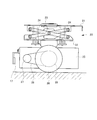
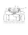

Classifications
-
- B—PERFORMING OPERATIONS; TRANSPORTING
- B60—VEHICLES IN GENERAL
- B60B—VEHICLE WHEELS; CASTORS; AXLES FOR WHEELS OR CASTORS; INCREASING WHEEL ADHESION
- B60B33/00—Castors in general ; Anti-clogging castors
-
- B—PERFORMING OPERATIONS; TRANSPORTING
- B62—LAND VEHICLES FOR TRAVELLING OTHERWISE THAN ON RAILS
- B62B—HAND-PROPELLED VEHICLES, e.g. HAND CARTS OR PERAMBULATORS; SLEDGES
- B62B3/00—Hand carts having more than one axis carrying transport wheels; Steering devices therefor; Equipment therefor
- B62B3/001—Steering devices
-
- B—PERFORMING OPERATIONS; TRANSPORTING
- B60—VEHICLES IN GENERAL
- B60B—VEHICLE WHEELS; CASTORS; AXLES FOR WHEELS OR CASTORS; INCREASING WHEEL ADHESION
- B60B2200/00—Type of product being used or applied
- B60B2200/40—Articles of daily use
- B60B2200/43—Carts
-
- B—PERFORMING OPERATIONS; TRANSPORTING
- B62—LAND VEHICLES FOR TRAVELLING OTHERWISE THAN ON RAILS
- B62B—HAND-PROPELLED VEHICLES, e.g. HAND CARTS OR PERAMBULATORS; SLEDGES
- B62B2301/00—Wheel arrangements; Steering; Stability; Wheel suspension
- B62B2301/02—Wheel arrangements; Steering; Stability; Wheel suspension comprising wheels for longitudinal travelling and wheels for lateral travelling
Definitions
- the present invention relates to an automatic guided vehicle. More specifically, the present invention provides the reverse traveling performance and the front / rear / left / right (four-way) traveling performance equivalent to those of the forward traveling even in the automatic guided vehicle having one drive unit at the bottom of the carriage body. It is devised so that it can be made to have a good running performance.
- This simple automatic guided vehicle is configured by including a drive unit, a control unit, and the like on a carriage.
- FIG. 15 which is a side view during forward travel
- FIG. 16 which is a side view during reverse travel
- FIG. 17 which is a rear view.
- a cart body 11 and a hand handle 12 are configured by assembling a pipe frame.
- a pair of universal caster wheels 13 are attached to the bottom of the cart body 11 on the front side thereof, and a pair of fixed caster wheels 14 are attached to the rear side thereof.
- a front bumper 15 is disposed at the front end edge of the cart body 11, and a rear bumper 16 is disposed at the rear end edge of the cart body 11.
- a drive unit 20 is disposed at the bottom of the carriage body 11.
- a control unit 30, a battery 31, an operation switch panel 32, and the like are attached to the hand handle 12.
- a forward travel sensor 17 is attached to the front side of the drive unit 20, and a reverse travel sensor 18 is attached to the cart body 11 behind the fixed caster wheel 14.
- FIG. 18 is a side view
- FIG. 19 which is a rear view.
- the upper frame 21 of the drive unit 20 is fixed to the bottom of the carriage body 11 of the carriage 10.
- the lower frame 22 is connected to the upper frame 21 through a pantograph connection mechanism 23 so as to be vertically movable.
- a compression coil spring 24 is interposed between the upper frame 21 and the lower frame 22, and the lower frame 22 is urged downward by the compression coil spring 24.
- the drive unit 25 is connected to the lower portion of the lower frame 22 so as to be rotatable in a horizontal plane (steering is rotatable around a vertical axis).
- the drive unit 25 has a pair of drive wheels 26.
- the drive unit 25 incorporates two drive motor mechanisms (not shown), and the drive force generated from each drive motor mechanism is applied to the pair of drive wheels 26 via the sprocket 27, the chain 28, and the sprocket 29. It is communicated individually. Therefore, the right drive wheel 26 and the left drive wheel 26 are driven to rotate by separate drive motor mechanisms.
- the simple automatic guided vehicle 1 travels by driving the pair of drive wheels 26 to rotate. Further, steering can be performed by changing the rotational speeds of the right and left drive wheels 26.
- the drive unit 20 arranged at the bottom of the carriage body 11 has a pair of drive wheels 26 that are independently rotated, and a drive unit 25 that is urged downward and is rotatable around the vertical axis. I have.
- the vehicle travels in the front-rear and left-right directions (four directions). Direction). Further, the reverse travel performance was worse than the forward travel performance.
- the travel route is detected by the travel sensor 18 during backward travel, and steering is performed according to the positional deviation between the travel route and the travel sensor 18, but the amount of steering is appropriate only after traveling backward by a certain distance. Since it was not known whether or not it was, there was a problem that response was poor and meandering was increased.
- ⁇ Two-drive unit type conventional technology> Therefore, a simple automatic guided vehicle including two drive units is used in order to be able to travel in the front-rear and left-right directions (four directions) and to improve the reverse traveling performance.
- FIG. 20 shows a two-drive unit type simple automatic guided vehicle 1a.
- a pair of free caster wheels 13a are attached to the bottom of the carriage body 11 of the carriage 10 on the front side, and a pair of free casters on the rear side.
- a caster wheel 13b is attached. In other words, all four wheels are free caster wheels.
- the drive unit 20a and the drive unit 20b are arranged at the bottom of the carriage body 11 while being shifted in the front-rear direction.
- the drive units 20a and 20b have the same configuration as the drive unit 20 shown in FIGS.
- a forward travel sensor 17a is attached to the front side of the drive unit 20a
- a reverse travel sensor 17b is attached to the rear side
- a forward travel sensor 18a is attached to the front side of the drive unit 20b
- a reverse travel sensor is attached to the rear side.
- the traveling sensor 18b is attached.
- the structure of other parts is the same as that of the simplified automatic guided vehicle 1 shown in FIGS. 15 to 19, and parts having the same functions are denoted by the same reference numerals, and redundant description is omitted.
- the travel path is detected by the forward travel sensors 17a and 18a, and the drive wheels 26 of the drive units 20a and 20b rotate forwardly to travel forward with good steering performance.
- the travel route is detected by the reverse travel sensors 17b and 18b, and the drive wheels 26 of the drive units 20a and 20b rotate reversely to travel backward with good steering performance.
- the direction of the drive unit 25 of the drive units 20a, 20b is turned 90 degrees right in the horizontal plane with respect to the direction of the drive unit 25 of the drive units 20a, 20b during forward / reverse travel.
- the drive wheels 26 of the drive units 20a and 20b can rotate and travel rightward with good steering performance.
- the drive unit 25 of the drive units 20a, 20b is turned 90 degrees left in the horizontal plane with respect to the drive unit 25 of the drive units 20a, 20b during forward / reverse travel.
- the drive wheels 26 of the drive units 20a and 20b can rotate and travel leftward with good steering performance.
- the backward traveling performance and the front / rear / right / left (four directions) traveling performance can be made to be good traveling performance equivalent to that during forward traveling.
- the present invention has a good traveling performance equivalent to that during forward traveling, such as backward traveling performance and front / rear / left / right (four-way) traveling performance, even if there is only one drive unit provided in the cart body.
- An object of the present invention is to provide an automatic guided vehicle that can be used.
- the configuration of the present invention for solving the above problems is as follows.
- One drive unit is disposed at the bottom of the cart body, and a pair of special caster wheels are attached to the front side of the bottom of the cart body, and a pair of special caster wheels are attached to the rear side of the bottom of the cart body.
- the special caster wheel is An omni wheel having a wheel body fixed to a shaft, and a plurality of barrel rollers disposed at a plurality of locations along the circumferential direction of the circumferential surface of the wheel body; A support structure for rotatably supporting the shaft; A wheel body rotation fixing function unit that is attached to the support structure unit and can restrain the rotation of the shaft.
- the special caster wheel is arranged in a state where the shaft center of the shaft extends in the front-rear direction of the cart body.
- the configuration of the present invention is as follows.
- the wheel body rotation fixing function unit By controlling the wheel body rotation fixing function unit, During forward traveling, the rotation of the shaft of the pair of special caster wheels on the front side is allowed and the rotation of the shaft of the pair of special caster wheels on the rear side is restricted,
- the vehicle When the vehicle is traveling in reverse, it has a control unit that allows rotation of the shafts of the pair of special caster wheels on the rear side and restricts rotation of the shafts of the pair of special caster wheels on the front side.
- the configuration of the present invention is as follows.
- One drive unit is disposed at the bottom of the cart body, and a pair of special caster wheels are attached to the front side of the bottom of the cart body, and a pair of special caster wheels are attached to the rear side of the bottom of the cart body.
- the special caster wheel is A wheel body that is attached to a shaft and rotates integrally with the shaft in the rotational direction of the shaft, but is slidable in the axial direction of the shaft, and a plurality of portions disposed at a plurality of locations along the circumferential direction of the peripheral surface of the wheel body
- An omni wheel having a barrel-shaped roller, A support structure for rotatably supporting the shaft; A first rotation-fixed wedge fixed to the shaft, and the first rotation with the wheel body interposed between the first main body and the shaft.
- a second rotation fixing wedge disposed on the side opposite to the fixed wedge, and the first and second rotation fixing wedges by pushing the second rotation fixing wedge and the wheel body toward the first rotation fixing wedge.
- a barrel-type roller rotation fixing function unit having a push-back unit that allows the rotation of the barrel-type roller by separating the second rotation-fixed wedge from the barrel-type roller.
- the special caster wheel is arranged in a state in which the shaft center of the shaft extends in the vehicle width direction of the cart body.
- the configuration of the present invention is as follows.
- the barrel-type roller rotation fixing function unit By controlling the barrel-type roller rotation fixing function unit, During forward traveling, the rotation of the barrel roller of the pair of special caster wheels on the front side is allowed and the rotation of the barrel roller of the pair of special caster wheels on the rear side is restricted,
- the vehicle When the vehicle is traveling backward, it has a control unit that allows rotation of the barrel rollers of the pair of special caster wheels on the rear side and restricts rotation of the barrel rollers of the pair of special caster wheels on the front side.
- the configuration of the present invention is as follows.
- One drive unit is disposed at the bottom of the cart body, and a pair of special caster wheels are attached to the front side of the bottom of the cart body, and a pair of special caster wheels are attached to the rear side of the bottom of the cart body.
- the special caster wheel is A wheel body that is attached to a shaft and rotates integrally with the shaft with respect to the rotation direction of the shaft, but is slidable with respect to the axial direction of the shaft, and a plurality of portions disposed at a plurality of locations along the circumferential direction of the peripheral surface of the wheel body
- An omni wheel having a barrel-shaped roller, A support structure for rotatably supporting the shaft; A wheel body rotation fixing function unit that is attached to the support structure unit and can restrain rotation of the shaft; A first rotation-fixed wedge fixed to the shaft, and the first rotation with the wheel body interposed between the first main body and the shaft.
- a second rotation fixing wedge disposed on the side opposite to the fixed wedge, and the first and second rotation fixing wedges by pushing the second rotation fixing wedge and the wheel body toward the first rotation fixing wedge.
- a barrel-type roller rotation fixing function unit having a push-back unit that allows the rotation of the barrel-type roller by separating the second rotation-fixed wedge from the barrel-type roller.
- the special caster wheel is arranged in a state in which the shaft center of the shaft extends in the vehicle width direction of the cart body.
- the configuration of the present invention is as follows.
- the rotation of the barrel roller is restricted while allowing the rotation of the shaft of the pair of special caster wheels on the front side and the barrel type roller while allowing the rotation of the shaft of the pair of special caster wheels on the rear side
- the rotation of the barrel roller while restricting the rotation of the shaft of the pair of special caster wheels on the rear side and the rotation of the shaft of the barrel of the special caster wheel on the front side is permitted
- traveling rightward the rotation of the shaft of the pair of special caster wheels on the right side and the rotation of the barrel type roller is allowed and the rotation of the barrel type rollers of the pair of special caster wheels on the left side is permitted, and the rotation of the shaft is restricted.
- the shaft of the right pair of special caster wheels and the barrel-shaped roller are allowed to rotate, and the rotation of the barrel roller shaft of the pair of left-hand special caster wheels is permitted while restraining the rotation of the shaft. It has a control part.
- the configuration of the present invention is as follows.
- the drive unit has a pair of drive wheels that are independently driven to rotate, and includes a drive unit that is capable of steering and turning about a vertical axis.
- the reverse traveling performance and the forward / backward / left / right (four directions) traveling performance are as good as when traveling forward. Can be performance.
- the device configuration can be simplified and the manufacturing cost can be reduced.
- FIG. 3 is a side view showing a simplified automatic guided vehicle according to the first embodiment.
- the top view which shows simply the simple automatic guided vehicle of Example 1.
- FIG. The structure figure which shows the 2nd special free caster wheel.
- FIG. 6 is a side view showing a simple automatic guided vehicle according to a third embodiment.
- the top view which shows simply the simple automatic guided vehicle of Example 3.
- FIG. The side view which shows the conventional simple type automatic guided vehicle.
- the side view which shows the conventional simple type automatic guided vehicle.
- the rear view which shows the conventional simple type automatic guided vehicle.
- the side view which shows a drive unit The rear view which shows a drive unit.
- Example 1 is a simple automatic guided vehicle according to a first example in which reverse traveling performance is improved.
- a special universal caster wheel used in the simplified automatic guided vehicle of the first embodiment will be described first.
- This special caster wheel has a configuration in which an omni wheel is provided with a wheel body rotation fixing function portion (electromagnetic brake).
- FIG. 1 is a structural diagram illustrating a special universal caster wheel 100 used in a simple automatic guided vehicle according to a first embodiment.
- FIG. 1 (a) is a left side view
- FIG. 1 (b) is a cross-sectional view viewed from the front side.
- FIG. 1C is a right side view.
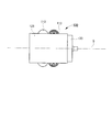
- FIG. 2 is a plan view showing the special universal caster wheel 100.
- the special caster wheel 100 includes an omni wheel 110, a support structure 120, and an electromagnetic brake 130 as a wheel body rotation fixing function unit.
- a wheel body 112 is fixed to a shaft 111.
- a plurality of barrel rollers 113 are arranged at a plurality of locations along the circumferential direction of the wheel main body 112. At this time, the rotational direction of each barrel roller 113 is orthogonal to the rotational direction of the shaft 111 and the wheel body 112.
- the pair of brackets 121 and 122 of the support structure portion 120 rotatably supports the shaft 111 via bearing portions (roller bearings) 123 and 124.
- the upper sides of the brackets 121 and 122 are fixed to the upper frame 125.
- the electromagnetic brake 130 is fixed to the bracket 122.
- the electromagnetic brake 130 When the electromagnetic brake 130 is energized, the brake operation is performed and the rotation of the shaft 111 is restricted.
- the demagnetization When the demagnetization is performed, the brake operation is released and the rotation of the shaft 111 is allowed.
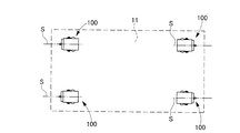
- FIG. 3 which is a side view of the simplified automatic guided vehicle 1-1 according to the first embodiment provided with the above-described special caster wheel 100, and a plan view simply showing the mounting state of the special caster wheel 100. This will be described with reference to FIG.
- a cart body 11 and a hand handle 12 are configured by assembling a pipe frame.
- a pair of special caster wheels 100 are attached to the bottom of the cart body 11 on the front side, and a pair of special caster wheels 100 are attached to the rear side. That is, the upper frame 125 of each special caster wheel 100 is fixed to the bottom portion of the cart body 11.
- the pair of special caster wheels 100 on the front side and the pair of special caster wheels 100 on the rear side are arranged in a state where the axis S of the shaft 111 extends in the front-rear direction.
- a front bumper 15 is disposed at the front end edge of the cart body 11, and a rear bumper 16 is disposed at the rear end edge of the cart body 11.
- a drive unit 20 is disposed at the bottom of the carriage body 11.
- the drive unit 20 has the same configuration as that described in the prior art (see FIGS. 18 and 19), and the drive unit 25 of the drive unit 20 has a pair of drive wheels 26 that are independently driven to rotate.
- the steering wheel 25 can be rotated around the vertical axis while being biased downward.
- the configuration and operation of other parts of the drive unit 20 are the same as those described in the prior art, and detailed description thereof is omitted.
- a forward travel sensor 17 is attached to the front side of the drive unit 20, and a reverse travel sensor 18 is attached to the rear side of the drive unit 20.
- a control unit 30, a battery 31, an operation switch panel 32, and the like are attached to the hand handle 12.
- the control unit 30 controls the rotation of the drive wheels 26 of the drive unit 20 and the excitation / demagnetization control of the electromagnetic brakes 130 of the special universal caster wheels 100 in response to a command from the operation switch panel 32.
- the control unit 30 demagnetizes the electromagnetic brake 130 of the pair of special caster wheels 100 on the front side, and a pair of special swivels on the rear side.
- the electromagnetic brake 130 of the caster wheel 100 is in an excited state.
- the barrel roller 113 rotates and the rotation of the wheel body 112 is allowed, and the same function as a normal universal caster wheel is achieved. That is, the barrel roller 113 rotates while being in contact with the floor surface, and the wheel main body 112 rotates according to the steering.
- the barrel roller 113 rotates but the rotation of the wheel body 112 is restricted, and functions equivalent to a normal fixed caster wheel.
- the barrel roller 113 rotates while being in contact with the floor surface, the wheel body 112 does not rotate, and the orientation of the pair of special caster wheels 100 on the rear side is fixed reliably and reliably.
- the pair of special caster wheels 100 on the front side performs the same function as a normal caster wheel
- the pair of special caster wheels 100 on the rear side performs the same function as a normal fixed caster wheel.
- the control unit 30 demagnetizes the electromagnetic brake 130 of the pair of special caster wheels 100 on the rear side, and a pair of special universal on the front side.
- the electromagnetic brake 130 of the caster wheel 100 is in an excited state.
- the rotation of the shaft 111 and the wheel main body 112 is allowed in the pair of special caster wheels 100 on the rear side, while the rotation of the shaft 111 and the wheel main body 112 is restricted in the pair of special caster wheels 100 on the front side.
- the barrel-shaped roller 113 rotates and the wheel body 112 is allowed to rotate, so that the same function as that of a normal universal caster wheel is achieved. That is, the barrel roller 113 rotates while being in contact with the floor surface, and the wheel main body 112 rotates according to the steering.
- the barrel roller 113 rotates but the rotation of the wheel main body 112 is restricted, and the same function as a normal fixed caster wheel is achieved.
- the barrel roller 113 rotates while being in contact with the floor surface, the wheel body 112 does not rotate, and the orientation of the pair of special caster wheels 100 on the front side is reliably and reliably fixed.
- the pair of special caster wheels 100 on the rear side performs the same function as a normal caster wheel
- the pair of special caster wheels 100 on the front side performs the same function as a normal fixed caster wheel.
- Example 2 is a simple automatic guided vehicle according to a second example in which reverse traveling performance is improved.
- a special universal caster wheel used in the simplified automatic guided vehicle of Example 2 will be described first.
- This special caster wheel has a configuration in which an omni wheel is provided with a barrel-type roller rotation fixing function portion.
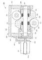
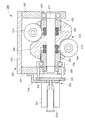
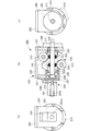
- FIG. 5 and 6 are structural views showing a special universal caster wheel 200 used in the simplified automatic guided vehicle of Example 2, and FIG. 5 shows a state in which the rotation of the barrel roller is fixed (constrained), FIG. 6 shows a state in which the barrel roller is free to rotate. 7 is a right side view showing the special universal caster wheel 200, and FIG. 8 is a plan view.
- the special caster wheel 200 includes an omni wheel 210, a support structure 220, and a barrel roller rotation fixing function 230.
- a wheel body 212 is attached to the shaft 211.
- the shaft 211 has a cylindrical shape at both ends thereof, but has a hexagonal column shape at other portions except both ends, and the wheel body 212 is integrated with the shaft 211 with respect to the rotation direction of the shaft 211.
- the shaft 211 is slidable in the axial direction.
- a plurality of barrel rollers 213 are arranged at a plurality of locations along the circumferential direction of the wheel body 212. At this time, the rotation direction of each barrel roller 213 is orthogonal to the rotation direction of the shaft 211 and the wheel body 212.
- the pair of brackets 221 and 222 of the support structure portion 220 rotatably supports the shaft 211 via bearing portions (roller bearings) 223 and 224.
- the upper sides of the brackets 221 and 222 are fixed to the upper frame 225.
- the barrel-type roller rotation fixing function unit 230 includes an electromagnetic solenoid 231, rotation fixing wedges 232, 233, and the like.
- the electromagnetic solenoid (pushing part) 231 is fixed to the bracket 221 via a mounting plate 234.
- the rotation fixing wedges 232 and 233 are disposed on the shaft 211 with the wheel body 212 sandwiched therebetween.
- one rotation fixing wedge 232 is fixed to the shaft 211.
- the other rotation fixing wedge 233 rotates integrally with the shaft 211 with respect to the rotation direction of the shaft 211, but is attached to the shaft 211 so as to be slidable with respect to the axial center direction of the shaft 211.
- a compression coil spring (push-back portion) 235 that generates a spring force that separates the rotation fixing wedge 232 and the wheel main body 212 is disposed between the rotation fixing wedge 232 and the wheel main body 212.
- a compression coil spring (push-back portion) 236 that generates a spring force that separates the two is disposed between them.
- the slide shaft 231a of the electromagnetic solenoid 231 is connected to the rotation fixed wedge 233 via the connecting plate 237, the connecting shaft 238, and the connecting rotary bearing 239.
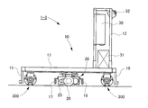
- FIG. 9 which is a side view of the simplified automatic guided vehicle 1-2 according to the second embodiment provided with the above-described special caster wheel 200, and a plan view simply showing the mounting state of the special caster wheel 200. This will be described with reference to FIG.
- a cart body 11 and a hand handle 12 are configured by assembling a pipe frame.
- a pair of special caster wheels 200 are attached to the bottom of the cart body 11 on the front side, and a pair of special caster wheels 200 are attached to the rear side.
- the upper frame 225 of each special caster wheel 200 is fixed to the bottom of the carriage body 11.
- the pair of special caster wheels 200 on the front side and the pair of special caster wheels 200 on the rear side are arranged in a state where the axis S of the shaft 211 extends in the left-right (vehicle width) direction.
- a front bumper 15 is disposed at the front end edge of the cart body 11, and a rear bumper 16 is disposed at the rear end edge of the cart body 11.
- a drive unit 20 is disposed at the bottom of the carriage body 11.
- the drive unit 20 has the same configuration as that described in the prior art (see FIGS. 18 and 19), and the drive unit 25 of the drive unit 20 has a pair of drive wheels 26 that are independently driven to rotate.
- the steering wheel 25 can be rotated around the vertical axis while being biased downward.
- the configuration and operation of other parts of the drive unit 20 are the same as those described in the prior art, and detailed description thereof is omitted.
- a forward travel sensor 17 is attached to the front side of the drive unit 20, and a reverse travel sensor 18 is attached to the rear side of the drive unit 20.
- a control unit 30, a battery 31, an operation switch panel 32, and the like are attached to the hand handle 12.
- the control unit 30 controls the rotation of the drive wheels 26 of the drive unit 20 and controls the excitation / demagnetization of the electromagnetic solenoids 231 of the special universal caster wheels 200 in response to a command from the operation switch panel 32.
- the control unit 30 demagnetizes the electromagnetic solenoid 231 of the pair of special caster wheels 200 on the front side and a pair of special swivels on the rear side.
- the electromagnetic solenoid 231 of the caster wheel 200 is in an excited state.
- the pair of special caster wheels 200 on the front side allows the barrel-shaped roller 213 to rotate
- the pair of special caster wheels 200 on the rear side restricts the rotation of the barrel-shaped roller 213.
- the wheel main body 212 rotates and the barrel-shaped roller 213 is allowed to rotate, and the same function as that of a normal universal caster wheel is achieved. That is, the wheel body 212 rotates and travels, and the barrel roller 213 rotates according to the steering.
- the wheel body 212 rotates, but the rotation of the barrel roller 213 is restricted, and functions equivalent to a normal fixed caster wheel. That is, the wheel body 212 rotates and the barrel roller 213 does not rotate, and the direction of the pair of special caster wheels 200 on the rear side is reliably and reliably fixed.
- the pair of special caster wheels 200 on the front side performs the same function as a normal caster wheel
- the pair of special caster wheels 200 on the rear side performs a function equivalent to a normal fixed caster wheel.
- the control unit 30 demagnetizes the electromagnetic solenoids 231 of the pair of special caster wheels 200 on the rear side, and sets a pair of special universal on the front side.
- the electromagnetic solenoid 231 of the caster wheel 200 is in an excited state.
- the rotation of the barrel roller 213 is allowed in the pair of special caster wheels 200 on the rear side, while the rotation of the barrel roller 213 is restrained in the pair of special caster wheels 200 on the front side.
- the wheel main body 212 rotates and the barrel-shaped roller 213 is allowed to rotate, so that the same function as a normal universal caster wheel is achieved. That is, the wheel body 212 rotates and travels, and the barrel roller 213 rotates according to the steering.
- the wheel body 212 rotates, but the rotation of the barrel roller 213 is restricted, and the same function as a normal fixed caster wheel is achieved. That is, the wheel body 212 rotates and the barrel roller 213 does not rotate, and the direction of the pair of special caster wheels 200 on the rear side is reliably and reliably fixed.
- the pair of special caster wheels 200 on the rear side performs the same function as a normal caster wheel
- the pair of special caster wheels 200 on the front side performs the same function as a normal fixed caster wheel.
- the third embodiment is a simple automatic guided vehicle that has improved traveling performance in the front-rear and left-right directions (four directions).
- a special universal caster wheel used in the simplified automatic guided vehicle of the third embodiment will be described first.
- This special caster wheel has a configuration in which an omni wheel is provided with a wheel body rotation fixing function part and a barrel roller rotation fixing function part.
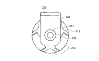
- FIG. 11 is a structural diagram showing a special universal caster wheel 300 used in the simplified automatic guided vehicle according to the third embodiment.
- FIG. 11 (a) is a left side view
- FIG. 11 (b) is a cross-sectional view seen from the front side.
- FIG. 11C is a right side view.
- FIG. 12 is a plan view.
- the special universal caster wheel 300 shown in these drawings is the special universal caster wheel 200 shown in FIG. 5 used in the second embodiment, that is, the omni wheel 210 provided with the barrel-type roller rotation fixing function unit 230, An electromagnetic brake 330 serving as a wheel body rotation fixing function unit is provided.
- the electromagnetic brake 330 is fixed to the bracket 222.
- the brake operation is performed to restrain the rotation of the shaft 211, and when demagnetized, the brake operation is released to allow the rotation of the shaft 211.
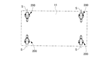
- FIG. 13 which is a side view of the simplified automatic guided vehicle 1-3 according to the third embodiment provided with the above-described special caster wheel 300, and a plan view simply showing the mounting state of the special caster wheel 300. This will be described with reference to FIG.
- a cart body 11 and a hand handle 12 are configured by assembling a pipe frame.
- a pair of special caster wheels 300 are attached to the bottom of the cart body 11 on the front side, and a pair of special caster wheels 300 are attached to the rear side. That is, the upper frame 225 of each special caster wheel 300 is fixed to the bottom portion of the cart body 11.
- the pair of special caster wheels 300 on the front side and the pair of special caster wheels 300 on the rear side are arranged in a state where the axis S of the shaft 211 extends in the left-right (vehicle width) direction.
- a front bumper 15 is disposed at the front end edge of the cart body 11, and a rear bumper 16 is disposed at the rear end edge of the cart body 11.
- a drive unit 20 is disposed at the bottom of the carriage body 11.
- the drive unit 20 has the same configuration as that described in the prior art (see FIGS. 18 and 19), and the drive unit 25 of the drive unit 20 has a pair of drive wheels 26 that are independently driven to rotate.
- the steering wheel 25 can be rotated around the vertical axis while being biased downward.
- the configuration and operation of other parts of the drive unit 20 are the same as those described in the prior art, and detailed description thereof is omitted.
- a forward travel sensor 17 is attached to the front side of the drive unit 20, and a reverse travel sensor 18 is attached to the rear side of the drive unit 20.
- a control unit 30, a battery 31, an operation switch panel 32, and the like are attached to the hand handle 12.
- the control unit 30 controls the rotation of the drive wheels 26 of the drive unit 20 in response to a command from the operation switch panel 32, and performs excitation / demagnetization control of the electromagnetic solenoids 231 and electromagnetic brakes 330 of the special universal caster wheels 300. To do.
- the control unit 30 demagnetizes the electromagnetic solenoid 231 and turns off the electromagnetic brake 330 for the pair of special caster wheels 300 on the front side.
- the electromagnetic solenoid 231 is energized and the electromagnetic brake 330 is demagnetized.
- the barrel-shaped roller 213 and the wheel body 212 are allowed to rotate in the pair of special caster wheels 300 on the front side, while the rotation of the barrel-shaped roller 213 is restrained in the pair of special caster wheels 300 on the rear side. And the rotation of the wheel body 212 is allowed.
- the wheel main body 212 and the barrel-shaped roller 213 rotate, so that the same function as a normal universal caster wheel is achieved. That is, the wheel body 212 rotates and travels, and the barrel roller 213 rotates according to the steering.
- the wheel body 212 rotates but the rotation of the barrel roller 213 is restrained, and the same function as a normal fixed caster wheel is achieved. That is, the wheel body 212 rotates and the barrel roller 213 does not rotate, and the orientation of the pair of special caster wheels 300 on the rear side is fixed reliably with high reliability.
- the pair of special caster wheels 300 on the front side perform the same function as a normal caster wheel
- the pair of special caster wheels 300 on the rear side perform a function equivalent to a normal fixed caster wheel.
- the control unit 30 In order to travel backward, when a reverse command is sent from the operation switch panel 32 to the control unit 30, the control unit 30 causes the electromagnetic solenoid 231 to be demagnetized and the electromagnetic brake 330 for the pair of special caster wheels 300 on the rear side. Is demagnetized, and for the pair of special caster wheels 300 on the front side, the electromagnetic solenoid 231 is energized and the electromagnetic brake 330 is demagnetized.
- the pair of special caster wheels 300 on the rear side allows the barrel roller 213 and the wheel body 212 to rotate, while the pair of special caster wheels 300 on the front side restrains the rotation of the barrel roller 213. And the rotation of the wheel body 212 is allowed.
- the wheel main body 212 and the barrel roller 213 rotate, so that the same function as that of a normal universal caster wheel is achieved. That is, the wheel body 212 rotates and travels, and the barrel roller 213 rotates according to the steering.
- the wheel body 212 rotates but the rotation of the barrel roller 213 is restricted, and the same function as a normal fixed caster wheel is achieved. That is, the wheel body 212 rotates and the barrel roller 213 does not rotate, and the direction of the pair of special caster wheels 300 on the front side is reliably and reliably fixed.
- the pair of special caster wheels 300 on the rear side performs the same function as a normal caster wheel
- the pair of special caster wheels 300 on the front side performs the same function as a normal fixed caster wheel.
- the control unit 30 causes the electromagnetic solenoid 231 to be demagnetized and the electromagnetic brake for the pair of special caster wheels 300 on the left side.
- the electromagnetic solenoid 231 is demagnetized and the electromagnetic brake 330 is excited.
- the barrel pair 213 and the wheel body 212 are allowed to rotate in the pair of left special caster wheels 300, while the barrel pair roller 213 is allowed to rotate in the pair of right special caster wheels 300. At the same time, the rotation of the wheel body 212 is restricted.
- the wheel main body 212 and the barrel roller 213 rotate, so that the same function as that of a normal universal caster wheel is achieved. That is, the barrel roller 213 rotates and travels, and the wheel main body 212 rotates according to steering.
- the barrel roller 213 rotates but the rotation of the wheel body 212 is restricted, and the same function as a normal fixed caster wheel is achieved. That is, the barrel-shaped roller 213 rotates and travels, the wheel body 212 does not rotate, and the direction of the pair of special caster wheels 300 on the right side is reliably and reliably fixed.
- the pair of special caster wheels 300 on the left side performs the same function as a normal caster wheel
- the pair of special caster wheels 300 on the right performs a function equivalent to a normal fixed caster wheel.
- the control unit 30 causes the electromagnetic solenoid 231 to be demagnetized and the electromagnetic brake for the pair of special caster wheels 300 on the right side.
- the electromagnetic solenoid 231 is demagnetized and the electromagnetic brake 330 is excited.
- the barrel pair 213 and the wheel body 212 are allowed to rotate in the pair of right special caster wheels 300, while the barrel pair roller 213 is allowed to rotate in the pair of left special caster wheels 300. At the same time, the rotation of the wheel body 212 is restricted.
- the wheel main body 212 and the barrel-shaped roller 213 rotate, so that the same function as a normal universal caster wheel is achieved. That is, the barrel roller 213 rotates and travels, and the wheel main body 212 rotates according to steering.
- the barrel roller 213 rotates but the rotation of the wheel body 212 is restricted, and the same function as a normal fixed caster wheel is achieved. That is, the barrel-shaped roller 213 rotates and travels, the wheel body 212 does not rotate, and the direction of the pair of left and right special caster wheels 300 is reliably and reliably fixed.
- the pair of right special caster wheels 300 on the right side performs the same function as that of a normal universal caster wheel
- the pair of special caster wheels 300 on the left side performs a function equivalent to that of a normal fixed caster wheel.
- the traveling performance in the front / rear / right / left directions (four directions) can be improved.
- the present invention can be used not only for a simple automatic guided vehicle but also for a normal automatic guided vehicle which is not a simple type.
Landscapes
- Engineering & Computer Science (AREA)
- Mechanical Engineering (AREA)
- Chemical & Material Sciences (AREA)
- Combustion & Propulsion (AREA)
- Transportation (AREA)
- Handcart (AREA)
Abstract
台車本体(10)の底部には、1台の駆動ユニット(20)が備えられており、台車の底部前側及び底部後側には、特殊自在キャスタ輪(100)が備えられている。特殊自在キャスタ輪(100)は、オムニホイール(110)と車輪本体の回転を拘束する電磁ブレーキ(130)を有している。後進走行時には、後側の特殊自在キャスタ輪(100)では、樽型ローラ(113)の回転により走行しホイール本体(112)の回転により操舵し、前側の特殊自在キャスタ輪(100)では、樽型ローラ(113)の回転により走行しホイール本体(112)の回転は電磁ブレーキ(130)により拘束して操舵しないようにする。これにより、1つの駆動ユニット(20)を備えた無人搬送車(1-1)でも、良好な後進走行性能を得ることができる。
Description
本発明は無人搬送車に関するものである。
更に説明すると、本発明は、台車本体の底部に1つの駆動ユニットを備えた無人搬送車であっても、後進走行性能や前後左右方向(四方向)走行性能を、前進走行時と同等な良好な走行性能とすることができるように工夫したものである。
更に説明すると、本発明は、台車本体の底部に1つの駆動ユニットを備えた無人搬送車であっても、後進走行性能や前後左右方向(四方向)走行性能を、前進走行時と同等な良好な走行性能とすることができるように工夫したものである。
無人搬送車の一種として簡易型無人搬送車がある。この簡易型無人搬送車は、台車に、駆動ユニット及び制御ユニット等を備えて構成したものである。
<1駆動ユニット型の従来技術>
ここで、前進走行時における側面図である図15、後進走行時における側面図である図16、背面図である図17を参照して、従来の簡易型無人搬送車を説明する。
図15~図17に示すように、この簡易型無人搬送車1の台車10では、パイプフレームを組み付けて台車本体11と手押しハンドル12が構成されている。台車本体11の底部には、その前側に一対の自在キャスタ輪13が取り付けられており、その後側に一対の固定キャスタ輪14が取り付けられている。
台車本体11の前端縁には前側のバンパー15が配置され、台車本体11の後端縁には後側のバンパー16が配置されている。
ここで、前進走行時における側面図である図15、後進走行時における側面図である図16、背面図である図17を参照して、従来の簡易型無人搬送車を説明する。
図15~図17に示すように、この簡易型無人搬送車1の台車10では、パイプフレームを組み付けて台車本体11と手押しハンドル12が構成されている。台車本体11の底部には、その前側に一対の自在キャスタ輪13が取り付けられており、その後側に一対の固定キャスタ輪14が取り付けられている。
台車本体11の前端縁には前側のバンパー15が配置され、台車本体11の後端縁には後側のバンパー16が配置されている。
更に、台車本体11の底部には駆動ユニット20が配置されている。
手押しハンドル12には、制御ユニット30、バッテリ31、操作スイッチパネル32等が取り付けられている。
駆動ユニット20の前側には、前進用の走行センサ17が取り付けられ、台車本体11には、固定キャスタ輪14よりも後ろ側に後進用の走行センサ18が取り付けられている。
手押しハンドル12には、制御ユニット30、バッテリ31、操作スイッチパネル32等が取り付けられている。
駆動ユニット20の前側には、前進用の走行センサ17が取り付けられ、台車本体11には、固定キャスタ輪14よりも後ろ側に後進用の走行センサ18が取り付けられている。
次に、駆動ユニット20の構造を、側面図である図18、及び、背面図である図19を参照して説明する。
図18及び図19に示すように、駆動ユニット20の上フレーム21は、台車10の台車本体11の底部に固定されている。下フレーム22はパンタグラフ式連結機構23を介して、上下移動可能な状態で上フレーム21に連結されている。
上フレーム21と下フレーム22との間には、圧縮コイルばね24が介装されており、下フレーム22は圧縮コイルばね24によって下方に向かって付勢されている。
図18及び図19に示すように、駆動ユニット20の上フレーム21は、台車10の台車本体11の底部に固定されている。下フレーム22はパンタグラフ式連結機構23を介して、上下移動可能な状態で上フレーム21に連結されている。
上フレーム21と下フレーム22との間には、圧縮コイルばね24が介装されており、下フレーム22は圧縮コイルばね24によって下方に向かって付勢されている。
駆動部25は、水平面内で回転自在(鉛直軸周りでステアリング回転自在)に、下フレーム22の下部に連結されている。駆動部25は一対の駆動輪26を有している。駆動部25には、2つの駆動モータ機構(図示省略)が内蔵されており、各駆動モータ機構から発生した駆動力が、スプロケット27,チェーン28及びスプロケット29を介して、一対の駆動輪26に個別に伝達されるようになっている。
このため右側の駆動輪26と左側の駆動輪26は、それぞれ別々の駆動モータ機構により回転駆動する。このように一対の駆動輪26が回転駆動することにより、簡易型無人搬送車1が走行する。また、右と左の駆動輪26の回転速度を変えることにより、操舵することができる。
このため右側の駆動輪26と左側の駆動輪26は、それぞれ別々の駆動モータ機構により回転駆動する。このように一対の駆動輪26が回転駆動することにより、簡易型無人搬送車1が走行する。また、右と左の駆動輪26の回転速度を変えることにより、操舵することができる。
結局、台車本体11の底部に配置される駆動ユニット20は、独立に回転駆動する一対の駆動輪26を有すると共に下方に付勢されつつ鉛直軸周りでステアリング回転自在となっている駆動部25を備えている。
ところで図15~図17に示すような、駆動ユニット20を1つ備えたタイプの無人搬送車1では、前後左右方向(四方向)走行、つまり、前後方向に走行することなく左右方向(車幅方向)に向かって走行することができなかった。
また、後進走行性能は前進走行性能に比べて悪かった。つまり、後進走行時には走行センサ18により走行経路を検出し、走行経路と走行センサ18との位置ズレに応じて操舵をしているが、ある程度の距離だけ後進走行した後でないと、操舵量が適当であったかどうかが分らないため、応答が悪く蛇行が大きくなるという問題があった。
また、後進走行性能は前進走行性能に比べて悪かった。つまり、後進走行時には走行センサ18により走行経路を検出し、走行経路と走行センサ18との位置ズレに応じて操舵をしているが、ある程度の距離だけ後進走行した後でないと、操舵量が適当であったかどうかが分らないため、応答が悪く蛇行が大きくなるという問題があった。
<2駆動ユニット型の従来技術>
そこで、前後左右方向(四方向)走行が可能で、且つ、後進走行性能を向上させるため、2個の駆動ユニットを備えた簡易型無人搬送車が使用されている。
そこで、前後左右方向(四方向)走行が可能で、且つ、後進走行性能を向上させるため、2個の駆動ユニットを備えた簡易型無人搬送車が使用されている。
図20は、2駆動ユニット型の簡易型無人搬送車1aであり、台車10の台車本体11の底部には、その前側に一対の自在キャスタ輪13aが取り付けられており、その後側に一対の自在キャスタ輪13bが取り付けられている。つまり、4輪とも自在キャスタ輪としている。
また、台車本体11の底部に、駆動ユニット20aと駆動ユニット20bを前後方向にずらして配置している。駆動ユニット20a,20bは、図15~図19に示す駆動ユニット20と同様な構成となっている。
駆動ユニット20aの前側には前進用の走行センサ17aが、後側には後進用の走行センサ17bが取り付けられ、駆動ユニット20bの前側には前進用の走行センサ18aが、後側には後進用の走行センサ18bが取り付けられている。
他の部分の構成は、図15~図19に示す簡易型無人搬送車1と同様であり、同一機能を果たす部分には同じ符号を付し、重複する説明は省略する。
駆動ユニット20aの前側には前進用の走行センサ17aが、後側には後進用の走行センサ17bが取り付けられ、駆動ユニット20bの前側には前進用の走行センサ18aが、後側には後進用の走行センサ18bが取り付けられている。
他の部分の構成は、図15~図19に示す簡易型無人搬送車1と同様であり、同一機能を果たす部分には同じ符号を付し、重複する説明は省略する。
前進走行時には前進用の走行センサ17a,18aにより走行経路を検出して駆動ユニット20a,20bの駆動輪26が正転回転して操舵性良く前進走行することができる。
後進走行時には後進用の走行センサ17b,18bにより走行経路を検出して駆動ユニット20a,20bの駆動輪26が逆転回転して操舵性良く後進走行することができる。
後進走行時には後進用の走行センサ17b,18bにより走行経路を検出して駆動ユニット20a,20bの駆動輪26が逆転回転して操舵性良く後進走行することができる。
右進走行時には、駆動ユニット20a,20bの駆動部25の向きを、前進・後進走行時の駆動ユニット20a,20bの駆動部25の向きに対して、水平面内で右90度旋回させた後に、駆動ユニット20a,20bの駆動輪26が回転して操舵性良く右進走行することができる。
左進走行時には、駆動ユニット20a,20bの駆動部25の向きを、前進・後進走行時の駆動ユニット20a,20bの駆動部25の向きに対して、水平面内で左90度旋回させた後に、駆動ユニット20a,20bの駆動輪26が回転して操舵性良く左進走行することができる。
左進走行時には、駆動ユニット20a,20bの駆動部25の向きを、前進・後進走行時の駆動ユニット20a,20bの駆動部25の向きに対して、水平面内で左90度旋回させた後に、駆動ユニット20a,20bの駆動輪26が回転して操舵性良く左進走行することができる。
かくして、図20に示す簡易型無人搬送車1aでは、後進走行性能や前後左右方向(四方向)走行性能を、前進走行時と同等な良好な走行性能とすることができる。
図20に示すように、4つの自在キャスタ輪13a,13bと、2台の駆動ユニット20a,20bを備えれば、良好な後進走行性能や前後左右方向(四方向)走行性能を得ることができる。
しかし、2台の駆動ユニット20a,20bが必要になるため、機台(台車)寸法が大きくなると共に、価格が高くなるという問題があった。
しかし、2台の駆動ユニット20a,20bが必要になるため、機台(台車)寸法が大きくなると共に、価格が高くなるという問題があった。
本発明は、上記従来技術に鑑み、台車本体に備える駆動ユニットが1台であっても、後進走行性能や前後左右方向(四方向)走行性能を、前進走行時と同等な良好な走行性能とすることができる無人搬送車を提供することを目的とする。
上記課題を解決する本発明の構成は、
台車本体の底部に1台の駆動ユニットが配置され、前記台車本体の底部の前側に一対の特殊自在キャスタ輪が取りつけられると共に前記台車本体の底部の後側に一対の特殊自在キャスタ輪が取りつけられており、
前記特殊自在キャスタ輪は、
シャフトに固定されたホイール本体と、前記ホイール本体の周面の周方向に沿う複数個所に配置した複数の樽型ローラを有するオムニホイールと、
前記シャフトを回転自在に支持する支持構造部と、
前記支持構造部に取り付けられており前記シャフトの回転を拘束することができるホイール本体回転固定機能部とでなり、
しかも、前記特殊自在キャスタ輪は、前記シャフトの軸心が前記台車本体の前後方向に伸びる状態で配置されていることを特徴とする。
台車本体の底部に1台の駆動ユニットが配置され、前記台車本体の底部の前側に一対の特殊自在キャスタ輪が取りつけられると共に前記台車本体の底部の後側に一対の特殊自在キャスタ輪が取りつけられており、
前記特殊自在キャスタ輪は、
シャフトに固定されたホイール本体と、前記ホイール本体の周面の周方向に沿う複数個所に配置した複数の樽型ローラを有するオムニホイールと、
前記シャフトを回転自在に支持する支持構造部と、
前記支持構造部に取り付けられており前記シャフトの回転を拘束することができるホイール本体回転固定機能部とでなり、
しかも、前記特殊自在キャスタ輪は、前記シャフトの軸心が前記台車本体の前後方向に伸びる状態で配置されていることを特徴とする。
また本発明の構成は、
前記ホイール本体回転固定機能部を制御することにより、
前進走行時には、前側の一対の特殊自在キャスタ輪のシャフトの回転を許容すると共に後側の一対の特殊自在キャスタ輪のシャフトの回転を拘束し、
後進走行時には、後側の一対の特殊自在キャスタ輪のシャフトの回転を許容すると共に前側の一対の特殊自在キャスタ輪のシャフトの回転を拘束する制御部を有することを特徴とする。
前記ホイール本体回転固定機能部を制御することにより、
前進走行時には、前側の一対の特殊自在キャスタ輪のシャフトの回転を許容すると共に後側の一対の特殊自在キャスタ輪のシャフトの回転を拘束し、
後進走行時には、後側の一対の特殊自在キャスタ輪のシャフトの回転を許容すると共に前側の一対の特殊自在キャスタ輪のシャフトの回転を拘束する制御部を有することを特徴とする。
また本発明の構成は、
台車本体の底部に1台の駆動ユニットが配置され、前記台車本体の底部の前側に一対の特殊自在キャスタ輪が取りつけられると共に前記台車本体の底部の後側に一対の特殊自在キャスタ輪が取りつけられており、
前記特殊自在キャスタ輪は、
シャフトに取り付けられて前記シャフトの回転方向に関して前記シャフトと一体に回転するが前記シャフトの軸方向に関してはスライド移動できるホイール本体と、前記ホイール本体の周面の周方向に沿う複数個所に配置した複数の樽型ローラを有するオムニホイールと、
前記シャフトを回転自在に支持する支持構造部と、
前記シャフトに固定された第1の回転固定クサビと、前記シャフトの回転方向に関して前記シャフトと一体に回転するが前記シャフトの軸方向に関してはスライド移動でき且つ前記ホイール本体を間にして第1の回転固定クサビと反対側に配置された第2の回転固定クサビと、第2の回転固定クサビ及び前記ホイール本体を第1の回転固定クサビ側に押し込んでいくことにより第1及び第2の回転固定クサビを前記樽型ローラに接触させて前記樽型ローラの回転を拘束させる押し込み部と、第2の回転固定クサビ及び前記ホイール本体を第1の回転固定クサビとは反対側に押し戻すことにより第1及び第2の回転固定クサビを前記樽型ローラから離間させて前記樽型ローラの回転を許容させる押し戻し部とを有する樽型ローラ回転固定機能部とでなり、
しかも、前記特殊自在キャスタ輪は、前記シャフトの軸心が前記台車本体の車幅方向に伸びる状態で配置されていることを特徴とする。
台車本体の底部に1台の駆動ユニットが配置され、前記台車本体の底部の前側に一対の特殊自在キャスタ輪が取りつけられると共に前記台車本体の底部の後側に一対の特殊自在キャスタ輪が取りつけられており、
前記特殊自在キャスタ輪は、
シャフトに取り付けられて前記シャフトの回転方向に関して前記シャフトと一体に回転するが前記シャフトの軸方向に関してはスライド移動できるホイール本体と、前記ホイール本体の周面の周方向に沿う複数個所に配置した複数の樽型ローラを有するオムニホイールと、
前記シャフトを回転自在に支持する支持構造部と、
前記シャフトに固定された第1の回転固定クサビと、前記シャフトの回転方向に関して前記シャフトと一体に回転するが前記シャフトの軸方向に関してはスライド移動でき且つ前記ホイール本体を間にして第1の回転固定クサビと反対側に配置された第2の回転固定クサビと、第2の回転固定クサビ及び前記ホイール本体を第1の回転固定クサビ側に押し込んでいくことにより第1及び第2の回転固定クサビを前記樽型ローラに接触させて前記樽型ローラの回転を拘束させる押し込み部と、第2の回転固定クサビ及び前記ホイール本体を第1の回転固定クサビとは反対側に押し戻すことにより第1及び第2の回転固定クサビを前記樽型ローラから離間させて前記樽型ローラの回転を許容させる押し戻し部とを有する樽型ローラ回転固定機能部とでなり、
しかも、前記特殊自在キャスタ輪は、前記シャフトの軸心が前記台車本体の車幅方向に伸びる状態で配置されていることを特徴とする。
また本発明の構成は、
前記樽型ローラ回転固定機能部を制御することにより、
前進走行時には、前側の一対の特殊自在キャスタ輪の樽型ローラの回転を許容すると共に後側の一対の特殊自在キャスタ輪の樽型ローラの回転を拘束し、
後進走行時には、後側の一対の特殊自在キャスタ輪の樽型ローラの回転を許容すると共に前側の一対の特殊自在キャスタ輪の樽型ローラの回転を拘束する制御部を有することを特徴とする。
前記樽型ローラ回転固定機能部を制御することにより、
前進走行時には、前側の一対の特殊自在キャスタ輪の樽型ローラの回転を許容すると共に後側の一対の特殊自在キャスタ輪の樽型ローラの回転を拘束し、
後進走行時には、後側の一対の特殊自在キャスタ輪の樽型ローラの回転を許容すると共に前側の一対の特殊自在キャスタ輪の樽型ローラの回転を拘束する制御部を有することを特徴とする。
また本発明の構成は、
台車本体の底部に1台の駆動ユニットが配置され、前記台車本体の底部の前側に一対の特殊自在キャスタ輪が取りつけられると共に前記台車本体の底部の後側に一対の特殊自在キャスタ輪が取りつけられており、
前記特殊自在キャスタ輪は、
シャフトに取りつけられて前記シャフトの回転方向に関して前記シャフトと一体に回転するが前記シャフトの軸方向に関してはスライド移動できるホイール本体と、前記ホイール本体の周面の周方向に沿う複数個所に配置した複数の樽型ローラを有するオムニホイールと、
前記シャフトを回転自在に支持する支持構造部と、
前記支持構造部に取り付けられており前記シャフトの回転を拘束することができるホイール本体回転固定機能部と、
前記シャフトに固定された第1の回転固定クサビと、前記シャフトの回転方向に関して前記シャフトと一体に回転するが前記シャフトの軸方向に関してはスライド移動でき且つ前記ホイール本体を間にして第1の回転固定クサビと反対側に配置された第2の回転固定クサビと、第2の回転固定クサビ及び前記ホイール本体を第1の回転固定クサビ側に押し込んでいくことにより第1及び第2の回転固定クサビを前記樽型ローラに接触させて前記樽型ローラの回転を拘束させる押し込み部と、第2の回転固定クサビ及び前記ホイール本体を第1の回転固定クサビとは反対側に押し戻すことにより第1及び第2の回転固定クサビを前記樽型ローラから離間させて前記樽型ローラの回転を許容させる押し戻し部とを有する樽型ローラ回転固定機能部とでなり、
しかも、前記特殊自在キャスタ輪は、前記シャフトの軸心が前記台車本体の車幅方向に伸びる状態で配置されていることを特徴とする。
台車本体の底部に1台の駆動ユニットが配置され、前記台車本体の底部の前側に一対の特殊自在キャスタ輪が取りつけられると共に前記台車本体の底部の後側に一対の特殊自在キャスタ輪が取りつけられており、
前記特殊自在キャスタ輪は、
シャフトに取りつけられて前記シャフトの回転方向に関して前記シャフトと一体に回転するが前記シャフトの軸方向に関してはスライド移動できるホイール本体と、前記ホイール本体の周面の周方向に沿う複数個所に配置した複数の樽型ローラを有するオムニホイールと、
前記シャフトを回転自在に支持する支持構造部と、
前記支持構造部に取り付けられており前記シャフトの回転を拘束することができるホイール本体回転固定機能部と、
前記シャフトに固定された第1の回転固定クサビと、前記シャフトの回転方向に関して前記シャフトと一体に回転するが前記シャフトの軸方向に関してはスライド移動でき且つ前記ホイール本体を間にして第1の回転固定クサビと反対側に配置された第2の回転固定クサビと、第2の回転固定クサビ及び前記ホイール本体を第1の回転固定クサビ側に押し込んでいくことにより第1及び第2の回転固定クサビを前記樽型ローラに接触させて前記樽型ローラの回転を拘束させる押し込み部と、第2の回転固定クサビ及び前記ホイール本体を第1の回転固定クサビとは反対側に押し戻すことにより第1及び第2の回転固定クサビを前記樽型ローラから離間させて前記樽型ローラの回転を許容させる押し戻し部とを有する樽型ローラ回転固定機能部とでなり、
しかも、前記特殊自在キャスタ輪は、前記シャフトの軸心が前記台車本体の車幅方向に伸びる状態で配置されていることを特徴とする。
また本発明の構成は、
前記ホイール本体回転固定機能部及び前記樽型ローラ回転固定機能部を制御することにより、
前進走行時には、前側の一対の特殊自在キャスタ輪のシャフト及び樽型ローラの回転を許容すると共に後側の一対の特殊自在キャスタ輪のシャフトの回転を許容しつつ樽型ローラの回転を拘束し、
後進走行時には、後側の一対の特殊自在キャスタ輪のシャフト及び樽型ローラの回転を許容すると共に前側の一対の特殊自在キャスタ輪のシャフトの回転を許容しつつ樽型ローラの回転を拘束し、
右進走行時には、右側の一対の特殊自在キャスタ輪のシャフト及び樽型ローラの回転を許容すると共に左側の一対の特殊自在キャスタ輪の樽型ローラの回転を許容しつつシャフトの回転を拘束し、
右進走行時には、右側の一対の特殊自在キャスタ輪のシャフト及び樽型ローラの回転を許容すると共に左側の一対の特殊自在キャスタ輪の樽型ローラシャフトの回転を許容しつつシャフトの回転を拘束する制御部を有することを特徴とする。
前記ホイール本体回転固定機能部及び前記樽型ローラ回転固定機能部を制御することにより、
前進走行時には、前側の一対の特殊自在キャスタ輪のシャフト及び樽型ローラの回転を許容すると共に後側の一対の特殊自在キャスタ輪のシャフトの回転を許容しつつ樽型ローラの回転を拘束し、
後進走行時には、後側の一対の特殊自在キャスタ輪のシャフト及び樽型ローラの回転を許容すると共に前側の一対の特殊自在キャスタ輪のシャフトの回転を許容しつつ樽型ローラの回転を拘束し、
右進走行時には、右側の一対の特殊自在キャスタ輪のシャフト及び樽型ローラの回転を許容すると共に左側の一対の特殊自在キャスタ輪の樽型ローラの回転を許容しつつシャフトの回転を拘束し、
右進走行時には、右側の一対の特殊自在キャスタ輪のシャフト及び樽型ローラの回転を許容すると共に左側の一対の特殊自在キャスタ輪の樽型ローラシャフトの回転を許容しつつシャフトの回転を拘束する制御部を有することを特徴とする。
また本発明の構成は、
前記駆動ユニットは、独立に回転駆動する一対の駆動輪を有し且つ鉛直軸周りでステアリング旋回自在な駆動部を備えていることを特徴とする。
前記駆動ユニットは、独立に回転駆動する一対の駆動輪を有し且つ鉛直軸周りでステアリング旋回自在な駆動部を備えていることを特徴とする。
本発明によれば、台車本体の底部に1つの駆動ユニットを備えた無人搬送車であっても、後進走行性能や前後左右方向(四方向)走行性能を、前進走行時と同等な良好な走行性能とすることができる。
また、駆動ユニットが1台だけであるので、機器構成を簡略化できると共に製造コストを削減することができる。
また、駆動ユニットが1台だけであるので、機器構成を簡略化できると共に製造コストを削減することができる。
以下、本発明の実施の形態について、実施例に基づき詳細に説明する。
実施例1は、後進走行性能を向上させた第1の例に係る簡易型無人搬送車である。
まず、実施例1の簡易型無人搬送車に用いる、特殊自在キャスタ輪について先に説明する。この特殊自在キャスタ輪は、オムニホイールにホイール本体回転固定機能部(電磁ブレーキ)を備えた構成となっている。
まず、実施例1の簡易型無人搬送車に用いる、特殊自在キャスタ輪について先に説明する。この特殊自在キャスタ輪は、オムニホイールにホイール本体回転固定機能部(電磁ブレーキ)を備えた構成となっている。
図1は、実施例1の簡易型無人搬送車に用いる特殊自在キャスタ輪100を示す構造図であり、図1(a)は左側面図、図1(b)は正面側から見た断面図、図1(c)は右側面図である。また、図2は特殊自在キャスタ輪100を示す平面図である。
図1及び図2に示すように、特殊自在キャスタ輪100は、オムニホイール110と、支持構造部120と、ホイール本体回転固定機能部としての電磁ブレーキ130とで構成されている。
図1及び図2に示すように、特殊自在キャスタ輪100は、オムニホイール110と、支持構造部120と、ホイール本体回転固定機能部としての電磁ブレーキ130とで構成されている。
オムニホイール110では、シャフト111にホイール本体112が固定されている。ホイール本体112の周面には、複数の樽型ローラ113が、ホイール本体112の周方向に沿う複数個所に配置されている。このとき、シャフト111及びホイール本体112の回転方向に対して、各樽型ローラ113の回転方向は直行している。
支持構造部120の一対のブラケット121,122は、軸受部(ローラベアリング)123,124を介してシャフト111を回転自在に支持している。ブラケット121,122の上辺は、上フレーム125に固定されている。
電磁ブレーキ130はブラケット122に固定されており、励磁されるとブレーキ動作をしてシャフト111の回転を拘束し、消磁されるとブレーキ動作を解除してシャフト111の回転を許容する。
次に、上記の特殊自在キャスタ輪100を備えた実施例1の簡易型無人搬送車1-1を、側面図である図3と、特殊自在キャスタ輪100の取付状態を簡易的に示す平面図である図4を参照して説明する。
図3及び図4に示すように、この簡易型無人搬送車1-1の台車10では、パイプフレームを組み付けて台車本体11と手押しハンドル12が構成されている。台車本体11の底部には、その前側に一対の特殊自在キャスタ輪100が取り付けられており、その後側に一対の特殊自在キャスタ輪100が取り付けられている。つまり、各特殊自在キャスタ輪100の上フレーム125が台車本体11の底部に固定されている。
しかも、前側の一対の特殊自在キャスタ輪100及び後側の一対の特殊自在キャスタ輪100は、シャフト111の軸心Sが前後方向に伸びる状態で配置されている。
台車本体11の前端縁には前側のバンパー15が配置され、台車本体11の後端縁には後側のバンパー16が配置されている。
しかも、前側の一対の特殊自在キャスタ輪100及び後側の一対の特殊自在キャスタ輪100は、シャフト111の軸心Sが前後方向に伸びる状態で配置されている。
台車本体11の前端縁には前側のバンパー15が配置され、台車本体11の後端縁には後側のバンパー16が配置されている。
更に、台車本体11の底部には駆動ユニット20が配置されている。この駆動ユニット20は、従来技術で説明したもの(図18、図19参照)と同構成であり、駆動ユニット20の駆動部25は独立に回転駆動する一対の駆動輪26を有し、駆動部25は下方に付勢されつつ鉛直軸周りでステアリング回転自在となっている。なお、駆動ユニット20の他の部分の構成・動作は、従来技術で説明したのと同じであり、詳細説明は省略する。
駆動ユニット20の前側には、前進用の走行センサ17が取り付けられ、駆動ユニット20の後側には、後進用の走行センサ18が取り付けられている。
駆動ユニット20の前側には、前進用の走行センサ17が取り付けられ、駆動ユニット20の後側には、後進用の走行センサ18が取り付けられている。
手押しハンドル12には、制御ユニット30、バッテリ31、操作スイッチパネル32等が取り付けられている。
制御ユニット30は、操作スイッチパネル32からの指令に応じて、駆動ユニット20の駆動輪26の回転制御をすると共に、各特殊自在キャスタ輪100の電磁ブレーキ130の励磁・消磁制御をする。
制御ユニット30は、操作スイッチパネル32からの指令に応じて、駆動ユニット20の駆動輪26の回転制御をすると共に、各特殊自在キャスタ輪100の電磁ブレーキ130の励磁・消磁制御をする。
前進走行するため、操作スイッチパネル32から前進指令を制御ユニット30に送ると、制御ユニット30は、前側の一対の特殊自在キャスタ輪100の電磁ブレーキ130を消磁状態とし、後側の一対の特殊自在キャスタ輪100の電磁ブレーキ130を励磁状態とする。
これにより、前側の一対の特殊自在キャスタ輪100ではシャフト111及びホイール本体112の回転が許容される一方で、後側の一対の特殊自在キャスタ輪100ではシャフト111及びホイール本体112の回転が拘束される。
この結果、前側の一対の特殊自在キャスタ輪100では、樽型ローラ113が回転すると共にホイール本体112の回転が許容され、通常の自在キャスタ輪と同等な機能を果たす。つまり、樽型ローラ113が床面に接地しつつ回転して走行し、操舵に応じてホイール本体112が回転する。
また、後側の一対の特殊自在キャスタ輪100では、樽型ローラ113は回転するがホイール本体112の回転は拘束され、通常の固定キャスタ輪と同等な機能を果たす。つまり、樽型ローラ113が床面に接地しつつ回転して走行し、ホイール本体112は回転せず後側の一対の特殊自在キャスタ輪100の向きは信頼性高く確実に固定される。
このように、前側の一対の特殊自在キャスタ輪100が通常の自在キャスタ輪と同等な機能を果たし、後側の一対の特殊自在キャスタ輪100が通常の固定キャスタ輪と同等な機能を果たすため、制御部30により前進走行するように制御ユニット20の駆動輪26を回転駆動すると、良好な走行性能で前進走行することができる。
後進走行するため、操作スイッチパネル32から後進指令を制御ユニット30に送ると、制御ユニット30は、後側の一対の特殊自在キャスタ輪100の電磁ブレーキ130を消磁状態とし、前側の一対の特殊自在キャスタ輪100の電磁ブレーキ130を励磁状態とする。
これにより、後側の一対の特殊自在キャスタ輪100ではシャフト111及びホイール本体112の回転が許容される一方で、前側の一対の特殊自在キャスタ輪100ではシャフト111及びホイール本体112の回転が拘束される。
この結果、後側の一対の特殊自在キャスタ輪100では、樽型ローラ113が回転すると共にホイール本体112の回転が許容され、通常の自在キャスタ輪と同等な機能を果たす。つまり、樽型ローラ113が床面に接地しつつ回転して走行し、操舵に応じてホイール本体112が回転する。
また、前側の一対の特殊自在キャスタ輪100では、樽型ローラ113は回転するがホイール本体112の回転は拘束され、通常の固定キャスタ輪と同等な機能を果たす。つまり、樽型ローラ113が床面に接地しつつ回転して走行し、ホイール本体112は回転せず前側の一対の特殊自在キャスタ輪100の向きは信頼性高く確実に固定される。
このように、後側の一対の特殊自在キャスタ輪100が通常の自在キャスタ輪と同等な機能を果たし、前側の一対の特殊自在キャスタ輪100が通常の固定キャスタ輪と同等な機能を果たすため、制御部30により後進走行するように制御ユニット20の駆動輪26を回転駆動すると、良好な走行性能で後進走行することができる。
つまり、後進走行性能を前進走行性能と同じ良好な性能にすることができる。
つまり、後進走行性能を前進走行性能と同じ良好な性能にすることができる。
実施例2は、後進走行性能を向上させた第2の例に係る簡易型無人搬送車である。
まず、実施例2の簡易型無人搬送車に用いる、特殊自在キャスタ輪について先に説明する。この特殊自在キャスタ輪は、オムニホイールに樽型ローラ回転固定機能部を備えた構成となっている。
まず、実施例2の簡易型無人搬送車に用いる、特殊自在キャスタ輪について先に説明する。この特殊自在キャスタ輪は、オムニホイールに樽型ローラ回転固定機能部を備えた構成となっている。
図5及び図6は、実施例2の簡易型無人搬送車に用いる特殊自在キャスタ輪200を示す構造図であり、図5は樽型ローラの回転が固定(拘束)されている状態を示し、図6は樽型ローラの回転がフリー(自由)になっている状態を示している。また、図7は特殊自在キャスタ輪200を示す右側面図であり、図8は平面図である。
これらの図に示すように、特殊自在キャスタ輪200は、オムニホイール210と、支持構造部220と、樽型ローラ回転固定機能部230とで構成されている。
オムニホイール210では、シャフト211にホイール本体212が取り付けられている。この場合、シャフト211は、その両端部では円柱状になっているが、両端部を除く他の部分では六角柱状になっており、ホイール本体212は、シャフト211の回転方向に関してはシャフト211と一体に回転するが、シャフト211の軸心方向に関してはスライド移動できるようになっている。
ホイール本体212の周面には、複数の樽型ローラ213が、ホイール本体212の周方向に沿う複数個所に配置されている。このとき、シャフト211及びホイール本体212の回転方向に対して、各樽型ローラ213の回転方向は直行している。
ホイール本体212の周面には、複数の樽型ローラ213が、ホイール本体212の周方向に沿う複数個所に配置されている。このとき、シャフト211及びホイール本体212の回転方向に対して、各樽型ローラ213の回転方向は直行している。
支持構造部220の一対のブラケット221,222は、軸受部(ローラベアリング)223,224を介してシャフト211を回転自在に支持している。ブラケット221,222の上辺は、上フレーム225に固定されている。
樽型ローラ回転固定機能部230は、電磁ソレノイド231、回転固定クサビ232,233等により構成されている。
電磁ソレノイド(押し込み部)231は、取付板234を介してブラケット221に固定されている。
回転固定クサビ232,233は、ホイール本体212を間に挟んだ状態で、シャフト211に配置されている。
しかも、一方の回転固定クサビ232はシャフト211に固定されている。また、他方の回転固定クサビ233は、シャフト211の回転方向に関してはシャフト211と一体に回転するが、シャフト211の軸心方向に関してはスライド移動できるように、シャフト211に取り付けられている。
回転固定クサビ232,233は、ホイール本体212を間に挟んだ状態で、シャフト211に配置されている。
しかも、一方の回転固定クサビ232はシャフト211に固定されている。また、他方の回転固定クサビ233は、シャフト211の回転方向に関してはシャフト211と一体に回転するが、シャフト211の軸心方向に関してはスライド移動できるように、シャフト211に取り付けられている。
そして、回転固定クサビ232とホイール本体212との間には、両者を離間させるようなばね力を発生する圧縮コイルばね(押し戻し部)235が配置されており、回転固定クサビ233とホイール本体212との間には、両者を離間させるようなばね力を発生する圧縮コイルばね(押し戻し部)236が配置されている。
電磁ソレノイド231のスライド軸231aは、連結板237,連結軸238及び連結用回転軸受239を介して、回転固定クサビ233に連結されている。
電磁ソレノイド231が励磁されると、スライド軸231aがシャフト211側に向かって引き込まれ、回転固定クサビ233及びホイール本体212が、回転固定クサビ232側に向かって押し込まれる。このため図5に示すように、回転固定クサビ232,233が樽型ローラ213に接触して樽型ローラ213の回転を拘束する。
電磁ソレノイド231が消磁されると、圧縮コイルばね235,236のばね力により、回転固定クサビ233及びホイール本体212がスライド軸231a側に向かって押され、スライド軸231aは押し戻される。このため、図6に示すように、回転固定クサビ232,233と樽型ローラ213との間に隙間ができ、樽型ローラ213の回転が許容される。
次に、上記の特殊自在キャスタ輪200を備えた実施例2の簡易型無人搬送車1-2を、側面図である図9と、特殊自在キャスタ輪200の取付状態を簡易的に示す平面図である図10を参照して説明する。
図9及び図10に示すように、この簡易型無人搬送車1-2の台車10では、パイプフレームを組み付けて台車本体11と手押しハンドル12が構成されている。台車本体11の底部には、その前側に一対の特殊自在キャスタ輪200が取り付けられており、その後側に一対の特殊自在キャスタ輪200が取り付けられている。つまり、各特殊自在キャスタ輪200の上フレーム225が台車本体11の底部に固定されている。
しかも、前側の一対の特殊自在キャスタ輪200及び後側の一対の特殊自在キャスタ輪200は、シャフト211の軸心Sが左右(車幅)方向に伸びる状態で配置されている。
台車本体11の前端縁には前側のバンパー15が配置され、台車本体11の後端縁には後側のバンパー16が配置されている。
しかも、前側の一対の特殊自在キャスタ輪200及び後側の一対の特殊自在キャスタ輪200は、シャフト211の軸心Sが左右(車幅)方向に伸びる状態で配置されている。
台車本体11の前端縁には前側のバンパー15が配置され、台車本体11の後端縁には後側のバンパー16が配置されている。
更に、台車本体11の底部には駆動ユニット20が配置されている。この駆動ユニット20は、従来技術で説明したもの(図18、図19参照)と同構成であり、駆動ユニット20の駆動部25は独立に回転駆動する一対の駆動輪26を有し、駆動部25は下方に付勢されつつ鉛直軸周りでステアリング回転自在となっている。なお、駆動ユニット20の他の部分の構成・動作は、従来技術で説明したのと同じであり、詳細説明は省略する。
駆動ユニット20の前側には、前進用の走行センサ17が取り付けられ、駆動ユニット20の後側には、後進用の走行センサ18が取り付けられている。
駆動ユニット20の前側には、前進用の走行センサ17が取り付けられ、駆動ユニット20の後側には、後進用の走行センサ18が取り付けられている。
手押しハンドル12には、制御ユニット30、バッテリ31、操作スイッチパネル32等が取り付けられている。
制御ユニット30は、操作スイッチパネル32からの指令に応じて、駆動ユニット20の駆動輪26の回転制御をすると共に、各特殊自在キャスタ輪200の電磁ソレノイド231の励磁・消磁制御をする。
制御ユニット30は、操作スイッチパネル32からの指令に応じて、駆動ユニット20の駆動輪26の回転制御をすると共に、各特殊自在キャスタ輪200の電磁ソレノイド231の励磁・消磁制御をする。
前進走行するため、操作スイッチパネル32から前進指令を制御ユニット30に送ると、制御ユニット30は、前側の一対の特殊自在キャスタ輪200の電磁ソレノイド231を消磁状態とし、後側の一対の特殊自在キャスタ輪200の電磁ソレノイド231を励磁状態とする。
これにより、前側の一対の特殊自在キャスタ輪200では樽型ローラ213の回転が許容される一方で、後側の一対の特殊自在キャスタ輪200では樽型ローラ213の回転が拘束される。
この結果、前側の一対の特殊自在キャスタ輪200では、ホイール本体212が回転すると共に樽型ローラ213の回転が許容され、通常の自在キャスタ輪と同等な機能を果たす。つまり、ホイール本体212が回転して走行し、操舵に応じて樽型ローラ213が回転する。
また、後側の一対の特殊自在キャスタ輪200では、ホイール本体212は回転するが樽型ローラ213の回転は拘束され、通常の固定キャスタ輪と同等な機能を果たす。つまり、ホイール本体212が回転して走行し、樽型ローラ213は回転せず後側の一対の特殊自在キャスタ輪200の向きは信頼性高く確実に固定される。
このように、前側の一対の特殊自在キャスタ輪200が通常の自在キャスタ輪と同等な機能を果たし、後側の一対の特殊自在キャスタ輪200が通常の固定キャスタ輪と同等な機能を果たすため、制御部30により前進走行するように制御ユニット20の駆動輪26を回転駆動すると、良好な走行性能で前進走行することができる。
後進走行するため、操作スイッチパネル32から後進指令を制御ユニット30に送ると、制御ユニット30は、後側の一対の特殊自在キャスタ輪200の電磁ソレノイド231を消磁状態とし、前側の一対の特殊自在キャスタ輪200の電磁ソレノイド231を励磁状態とする。
これにより、後側の一対の特殊自在キャスタ輪200では樽型ローラ213の回転が許容される一方で、前側の一対の特殊自在キャスタ輪200では樽型ローラ213の回転が拘束される。
この結果、後側の一対の特殊自在キャスタ輪200では、ホイール本体212が回転すると共に樽型ローラ213の回転が許容され、通常の自在キャスタ輪と同等な機能を果たす。つまり、ホイール本体212が回転して走行し、操舵に応じて樽型ローラ213が回転する。
また、前側の一対の特殊自在キャスタ輪200では、ホイール本体212は回転するが樽型ローラ213の回転は拘束され、通常の固定キャスタ輪と同等な機能を果たす。つまり、ホイール本体212が回転して走行し、樽型ローラ213は回転せず後側の一対の特殊自在キャスタ輪200の向きは信頼性高く確実に固定される。
このように、後側の一対の特殊自在キャスタ輪200が通常の自在キャスタ輪と同等な機能を果たし、前側の一対の特殊自在キャスタ輪200が通常の固定キャスタ輪と同等な機能を果たすため、制御部30により後進走行するように制御ユニット20の駆動輪26を回転駆動すると、良好な走行性能で後進走行することができる。
つまり、後進走行性能を前進走行性能と同じ良好な性能にすることができる。しかも、走行時には、車輪径の大きなホイール本体212が回転するため、溝や段差があっても、走行性能は殆ど落ちることはない。
つまり、後進走行性能を前進走行性能と同じ良好な性能にすることができる。しかも、走行時には、車輪径の大きなホイール本体212が回転するため、溝や段差があっても、走行性能は殆ど落ちることはない。
実施例3は、前後左右方向(四方向)走行性能を向上させた簡易型無人搬送車である。
まず、実施例3の簡易型無人搬送車に用いる、特殊自在キャスタ輪について先に説明する。この特殊自在キャスタ輪は、オムニホイールにホイール本体回転固定機能部と樽型ローラ回転固定機能部を備えた構成となっている。
まず、実施例3の簡易型無人搬送車に用いる、特殊自在キャスタ輪について先に説明する。この特殊自在キャスタ輪は、オムニホイールにホイール本体回転固定機能部と樽型ローラ回転固定機能部を備えた構成となっている。
図11は、実施例3の簡易型無人搬送車に用いる特殊自在キャスタ輪300を示す構造図であり、図11(a)は左側面図、図11(b)は正面側から見た断面図、図11(c)は右側面図である。また、図12は平面図である。
これらの図に示す特殊自在キャスタ輪300は、実施例2で用いた図5に示す特殊自在キャスタ輪200、即ち、オムニホイール210に樽型ローラ回転固定機能部230を備えたものに、更に、ホイール本体回転固定機能部としての電磁ブレーキ330を備えて構成されている。
電磁ブレーキ330はブラケット222に固定されており、励磁されるとブレーキ動作をしてシャフト211の回転を拘束し、消磁されるとブレーキ動作を解除してシャフト211の回転を許容する。
他の部分の構成は、図5,図6に示すものと同一であるため、同一部分には同一符号を付して重複する説明は省略する。
次に、上記の特殊自在キャスタ輪300を備えた実施例3の簡易型無人搬送車1-3を、側面図である図13と、特殊自在キャスタ輪300の取付状態を簡易的に示す平面図である図14を参照して説明する。
図13及び図14に示すように、この簡易型無人搬送車1-3の台車10では、パイプフレームを組み付けて台車本体11と手押しハンドル12が構成されている。台車本体11の底部には、その前側に一対の特殊自在キャスタ輪300が取り付けられており、その後側に一対の特殊自在キャスタ輪300が取り付けられている。つまり、各特殊自在キャスタ輪300の上フレーム225が台車本体11の底部に固定されている。
しかも、前側の一対の特殊自在キャスタ輪300及び後側の一対の特殊自在キャスタ輪300は、シャフト211の軸心Sが左右(車幅)方向に伸びる状態で配置されている。
台車本体11の前端縁には前側のバンパー15が配置され、台車本体11の後端縁には後側のバンパー16が配置されている。
しかも、前側の一対の特殊自在キャスタ輪300及び後側の一対の特殊自在キャスタ輪300は、シャフト211の軸心Sが左右(車幅)方向に伸びる状態で配置されている。
台車本体11の前端縁には前側のバンパー15が配置され、台車本体11の後端縁には後側のバンパー16が配置されている。
更に、台車本体11の底部には駆動ユニット20が配置されている。この駆動ユニット20は、従来技術で説明したもの(図18、図19参照)と同構成であり、駆動ユニット20の駆動部25は独立に回転駆動する一対の駆動輪26を有し、駆動部25は下方に付勢されつつ鉛直軸周りでステアリング回転自在となっている。なお、駆動ユニット20の他の部分の構成・動作は、従来技術で説明したのと同じであり、詳細説明は省略する。
駆動ユニット20の前側には、前進用の走行センサ17が取り付けられ、駆動ユニット20の後側には、後進用の走行センサ18が取り付けられている。
駆動ユニット20の前側には、前進用の走行センサ17が取り付けられ、駆動ユニット20の後側には、後進用の走行センサ18が取り付けられている。
手押しハンドル12には、制御ユニット30、バッテリ31、操作スイッチパネル32等が取り付けられている。
制御ユニット30は、操作スイッチパネル32からの指令に応じて、駆動ユニット20の駆動輪26の回転制御をすると共に、各特殊自在キャスタ輪300の電磁ソレノイド231及び電磁ブレーキ330の励磁・消磁制御をする。
制御ユニット30は、操作スイッチパネル32からの指令に応じて、駆動ユニット20の駆動輪26の回転制御をすると共に、各特殊自在キャスタ輪300の電磁ソレノイド231及び電磁ブレーキ330の励磁・消磁制御をする。
前進走行するため、操作スイッチパネル32から前進指令を制御ユニット30に送ると、制御ユニット30は、前側の一対の特殊自在キャスタ輪300については、電磁ソレノイド231を消磁状態とすると共に電磁ブレーキ330を消磁状態とし、後側の一対の特殊自在キャスタ輪300については、電磁ソレノイド231を励磁状態とすると共に電磁ブレーキ330を消磁状態とする。
これにより、前側の一対の特殊自在キャスタ輪300では樽型ローラ213及びホイール本体212の回転が許容される一方で、後側の一対の特殊自在キャスタ輪300では樽型ローラ213の回転が拘束されると共にホイール本体212の回転が許容される。
この結果、前側の一対の特殊自在キャスタ輪300では、ホイール本体212及び樽型ローラ213が回転するため、通常の自在キャスタ輪と同等な機能を果たす。つまり、ホイール本体212が回転して走行し、操舵に応じて樽型ローラ213が回転する。
また、後側の一対の特殊自在キャスタ輪300では、ホイール本体212は回転するが樽型ローラ213の回転は拘束され、通常の固定キャスタ輪と同等な機能を果たす。つまり、ホイール本体212が回転して走行し、樽型ローラ213は回転せず後側の一対の特殊自在キャスタ輪300の向きは信頼性高く確実に固定される。
このように、前側の一対の特殊自在キャスタ輪300が通常の自在キャスタ輪と同等な機能を果たし、後側の一対の特殊自在キャスタ輪300が通常の固定キャスタ輪と同等な機能を果たすため、制御部30により前進走行するように制御ユニット20の駆動輪26を回転駆動すると、良好な走行性能で前進走行することができる。
後進走行するため、操作スイッチパネル32から後進指令を制御ユニット30に送ると、制御ユニット30は、後側の一対の特殊自在キャスタ輪300については、電磁ソレノイド231を消磁状態とすると共に電磁ブレーキ330を消磁状態とし、前側の一対の特殊自在キャスタ輪300については、電磁ソレノイド231を励磁状態とすると共に電磁ブレーキ330を消磁状態とする。
これにより、後側の一対の特殊自在キャスタ輪300では樽型ローラ213及びホイール本体212の回転が許容される一方で、前側の一対の特殊自在キャスタ輪300では樽型ローラ213の回転が拘束されると共にホイール本体212の回転が許容される。
この結果、後側の一対の特殊自在キャスタ輪300では、ホイール本体212及び樽型ローラ213が回転するため、通常の自在キャスタ輪と同等な機能を果たす。つまり、ホイール本体212が回転して走行し、操舵に応じて樽型ローラ213が回転する。
また、前側の一対の特殊自在キャスタ輪300では、ホイール本体212は回転するが樽型ローラ213の回転は拘束され、通常の固定キャスタ輪と同等な機能を果たす。つまり、ホイール本体212が回転して走行し、樽型ローラ213は回転せず前側の一対の特殊自在キャスタ輪300の向きは信頼性高く確実に固定される。
このように、後側の一対の特殊自在キャスタ輪300が通常の自在キャスタ輪と同等な機能を果たし、前側の一対の特殊自在キャスタ輪300が通常の固定キャスタ輪と同等な機能を果たすため、制御部30により前進走行するように制御ユニット20の駆動輪26を回転駆動すると、良好な走行性能で後進走行することができる。
左進走行するため、操作スイッチパネル32から左進指令を制御ユニット30に送ると、制御ユニット30は、左側の一対の特殊自在キャスタ輪300については、電磁ソレノイド231を消磁状態とすると共に電磁ブレーキ330を消磁状態とし、右側の一対の特殊自在キャスタ輪300については、電磁ソレノイド231を消磁状態とすると共に電磁ブレーキ330を励磁状態とする。
これにより、左側の一対の特殊自在キャスタ輪300では樽型ローラ213及びホイール本体212の回転が許容される一方で、右側の一対の特殊自在キャスタ輪300では樽型ローラ213の回転が許容されると共にホイール本体212の回転が拘束される。
この結果、左側の一対の特殊自在キャスタ輪300では、ホイール本体212及び樽型ローラ213が回転するため、通常の自在キャスタ輪と同等な機能を果たす。つまり、樽型ローラ213が回転して走行し、操舵に応じてホイール本体212が回転する。
また、右側の一対の特殊自在キャスタ輪300では、樽型ローラ213は回転するがホイール本体212の回転は拘束され、通常の固定キャスタ輪と同等な機能を果たす。つまり、樽型ローラ213が回転して走行し、ホイール本体212は回転せず右側の一対の特殊自在キャスタ輪300の向きは信頼性高く確実に固定される。
このように、左側の一対の特殊自在キャスタ輪300が通常の自在キャスタ輪と同等な機能を果たし、右側の一対の特殊自在キャスタ輪300が通常の固定キャスタ輪と同等な機能を果たすため、制御部30により左進走行するように制御ユニット20の駆動輪26を回転駆動すると、良好な走行性能で左進走行することができる。
右進走行するため、操作スイッチパネル32から右進指令を制御ユニット30に送ると、制御ユニット30は、右側の一対の特殊自在キャスタ輪300については、電磁ソレノイド231を消磁状態とすると共に電磁ブレーキ330を消磁状態とし、左側の一対の特殊自在キャスタ輪300については、電磁ソレノイド231を消磁状態とすると共に電磁ブレーキ330を励磁状態とする。
これにより、右側の一対の特殊自在キャスタ輪300では樽型ローラ213及びホイール本体212の回転が許容される一方で、左側の一対の特殊自在キャスタ輪300では樽型ローラ213の回転が許容されると共にホイール本体212の回転が拘束される。
この結果、右側の一対の特殊自在キャスタ輪300では、ホイール本体212及び樽型ローラ213が回転するため、通常の自在キャスタ輪と同等な機能を果たす。つまり、樽型ローラ213が回転して走行し、操舵に応じてホイール本体212が回転する。
また、左側の一対の特殊自在キャスタ輪300では、樽型ローラ213は回転するがホイール本体212の回転は拘束され、通常の固定キャスタ輪と同等な機能を果たす。つまり、樽型ローラ213が回転して走行し、ホイール本体212は回転せず左側の一対の特殊自在キャスタ輪300の向きは信頼性高く確実に固定される。
このように、右側の一対の特殊自在キャスタ輪300が通常の自在キャスタ輪と同等な機能を果たし、左側の一対の特殊自在キャスタ輪300が通常の固定キャスタ輪と同等な機能を果たすため、制御部30により右進走行するように制御ユニット20の駆動輪26を回転駆動すると、良好な走行性能で左進走行することができる。
このように、4つの特殊自在キャスタ輪300の電磁ソレノイド231及び電磁ブレーキ330の励磁・消磁を制御することにより、前後左右方向(四方向)走行性能を向上させることができる。
本発明は、簡易型無人搬送車のみならず、簡易型ではない通常の無人搬送車にも利用可能である。
1,1a,1-1,1-2,1-3 簡易型無人搬送車
10 台車
11 台車本体
12 手押しハンドル
13,13a,13b 自在キャスタ輪
14 固定キャスタ輪
15,16 バンパー
17,17a,17b,18,18a,18b 走行センサ
20,20a,20b 駆動ユニット
25 駆動部
26 駆動輪
30 制御ユニット
31 バッテリ
32 操作スイッチパネル
100 特殊自在キャスタ輪
110 オムニホイール
111 シャフト
112 ホイール本体
113 樽型ローラ
120 支持構造部
121,122 ブラケット
123,124 軸受部
125 上フレーム
130,330 電磁ブレーキ(ホイール本体回転固定機能部)
200 特殊自在キャスタ輪
210 オムニホイール
211 シャフト
212 ホイール本体
213 樽型ローラ
220 支持構造部
221,222 ブラケット
223,224 軸受部
225 上フレーム
230 樽型ローラ回転固定機能部
231 電磁ソレノイド
231a スライド軸
232,233 回転固定クサビ
234 取付板
235,236 圧縮コイルばね
237 連結板
238 連結軸
239 連結用回転軸受
10 台車
11 台車本体
12 手押しハンドル
13,13a,13b 自在キャスタ輪
14 固定キャスタ輪
15,16 バンパー
17,17a,17b,18,18a,18b 走行センサ
20,20a,20b 駆動ユニット
25 駆動部
26 駆動輪
30 制御ユニット
31 バッテリ
32 操作スイッチパネル
100 特殊自在キャスタ輪
110 オムニホイール
111 シャフト
112 ホイール本体
113 樽型ローラ
120 支持構造部
121,122 ブラケット
123,124 軸受部
125 上フレーム
130,330 電磁ブレーキ(ホイール本体回転固定機能部)
200 特殊自在キャスタ輪
210 オムニホイール
211 シャフト
212 ホイール本体
213 樽型ローラ
220 支持構造部
221,222 ブラケット
223,224 軸受部
225 上フレーム
230 樽型ローラ回転固定機能部
231 電磁ソレノイド
231a スライド軸
232,233 回転固定クサビ
234 取付板
235,236 圧縮コイルばね
237 連結板
238 連結軸
239 連結用回転軸受
Claims (7)
- 台車本体の底部に1台の駆動ユニットが配置され、前記台車本体の底部の前側に一対の特殊自在キャスタ輪が取りつけられると共に前記台車本体の底部の後側に一対の特殊自在キャスタ輪が取りつけられており、
前記特殊自在キャスタ輪は、
シャフトに固定されたホイール本体と、前記ホイール本体の周面の周方向に沿う複数個所に配置した複数の樽型ローラを有するオムニホイールと、
前記シャフトを回転自在に支持する支持構造部と、
前記支持構造部に取り付けられており前記シャフトの回転を拘束することができるホイール本体回転固定機能部とでなり、
しかも、前記特殊自在キャスタ輪は、前記シャフトの軸心が前記台車本体の前後方向に伸びる状態で配置されていることを特徴とする無人搬送車。 - 前記ホイール本体回転固定機能部を制御することにより、
前進走行時には、前側の一対の特殊自在キャスタ輪のシャフトの回転を許容すると共に後側の一対の特殊自在キャスタ輪のシャフトの回転を拘束し、
後進走行時には、後側の一対の特殊自在キャスタ輪のシャフトの回転を許容すると共に前側の一対の特殊自在キャスタ輪のシャフトの回転を拘束する制御部を有することを特徴とする請求項1の無人搬送車。 - 台車本体の底部に1台の駆動ユニットが配置され、前記台車本体の底部の前側に一対の特殊自在キャスタ輪が取りつけられると共に前記台車本体の底部の後側に一対の特殊自在キャスタ輪が取りつけられており、
前記特殊自在キャスタ輪は、
シャフトに取り付けられて前記シャフトの回転方向に関して前記シャフトと一体に回転するが前記シャフトの軸方向に関してはスライド移動できるホイール本体と、前記ホイール本体の周面の周方向に沿う複数個所に配置した複数の樽型ローラを有するオムニホイールと、
前記シャフトを回転自在に支持する支持構造部と、
前記シャフトに固定された第1の回転固定クサビと、前記シャフトの回転方向に関して前記シャフトと一体に回転するが前記シャフトの軸方向に関してはスライド移動でき且つ前記ホイール本体を間にして第1の回転固定クサビと反対側に配置された第2の回転固定クサビと、第2の回転固定クサビ及び前記ホイール本体を第1の回転固定クサビ側に押し込んでいくことにより第1及び第2の回転固定クサビを前記樽型ローラに接触させて前記樽型ローラの回転を拘束させる押し込み部と、第2の回転固定クサビ及び前記ホイール本体を第1の回転固定クサビとは反対側に押し戻すことにより第1及び第2の回転固定クサビを前記樽型ローラから離間させて前記樽型ローラの回転を許容させる押し戻し部とを有する樽型ローラ回転固定機能部とでなり、
しかも、前記特殊自在キャスタ輪は、前記シャフトの軸心が前記台車本体の車幅方向に伸びる状態で配置されていることを特徴とする無人搬送車。 - 前記樽型ローラ回転固定機能部を制御することにより、
前進走行時には、前側の一対の特殊自在キャスタ輪の樽型ローラの回転を許容すると共に後側の一対の特殊自在キャスタ輪の樽型ローラの回転を拘束し、
後進走行時には、後側の一対の特殊自在キャスタ輪の樽型ローラの回転を許容すると共に前側の一対の特殊自在キャスタ輪の樽型ローラの回転を拘束する制御部を有することを特徴とする請求項3の無人搬送車。 - 台車本体の底部に1台の駆動ユニットが配置され、前記台車本体の底部の前側に一対の特殊自在キャスタ輪が取りつけられると共に前記台車本体の底部の後側に一対の特殊自在キャスタ輪が取りつけられており、
前記特殊自在キャスタ輪は、
シャフトに取りつけられて前記シャフトの回転方向に関して前記シャフトと一体に回転するが前記シャフトの軸方向に関してはスライド移動できるホイール本体と、前記ホイール本体の周面の周方向に沿う複数個所に配置した複数の樽型ローラを有するオムニホイールと、
前記シャフトを回転自在に支持する支持構造部と、
前記支持構造部に取り付けられており前記シャフトの回転を拘束することができるホイール本体回転固定機能部と、
前記シャフトに固定された第1の回転固定クサビと、前記シャフトの回転方向に関して前記シャフトと一体に回転するが前記シャフトの軸方向に関してはスライド移動でき且つ前記ホイール本体を間にして第1の回転固定クサビと反対側に配置された第2の回転固定クサビと、第2の回転固定クサビ及び前記ホイール本体を第1の回転固定クサビ側に押し込んでいくことにより第1及び第2の回転固定クサビを前記樽型ローラに接触させて前記樽型ローラの回転を拘束させる押し込み部と、第2の回転固定クサビ及び前記ホイール本体を第1の回転固定クサビとは反対側に押し戻すことにより第1及び第2の回転固定クサビを前記樽型ローラから離間させて前記樽型ローラの回転を許容させる押し戻し部とを有する樽型ローラ回転固定機能部とでなり、
しかも、前記特殊自在キャスタ輪は、前記シャフトの軸心が前記台車本体の車幅方向に伸びる状態で配置されていることを特徴とする無人搬送車。 - 前記ホイール本体回転固定機能部及び前記樽型ローラ回転固定機能部を制御することにより、
前進走行時には、前側の一対の特殊自在キャスタ輪のシャフト及び樽型ローラの回転を許容すると共に後側の一対の特殊自在キャスタ輪のシャフトの回転を許容しつつ樽型ローラの回転を拘束し、
後進走行時には、後側の一対の特殊自在キャスタ輪のシャフト及び樽型ローラの回転を許容すると共に前側の一対の特殊自在キャスタ輪のシャフトの回転を許容しつつ樽型ローラの回転を拘束し、
右進走行時には、右側の一対の特殊自在キャスタ輪のシャフト及び樽型ローラの回転を許容すると共に左側の一対の特殊自在キャスタ輪の樽型ローラの回転を許容しつつシャフトの回転を拘束し、
右進走行時には、右側の一対の特殊自在キャスタ輪のシャフト及び樽型ローラの回転を許容すると共に左側の一対の特殊自在キャスタ輪の樽型ローラシャフトの回転を許容しつつシャフトの回転を拘束する制御部を有することを特徴とする請求項5の無人搬送車。 - 前記駆動ユニットは、独立に回転駆動する一対の駆動輪を有し且つ鉛直軸周りでステアリング旋回自在な駆動部を備えていることを特徴とする請求項1ないし請求項6の無人搬送車。
Priority Applications (1)
| Application Number | Priority Date | Filing Date | Title |
|---|---|---|---|
| CN201280029062.4A CN103608238B (zh) | 2011-06-15 | 2012-06-13 | 无人搬运车 |
Applications Claiming Priority (2)
| Application Number | Priority Date | Filing Date | Title |
|---|---|---|---|
| JP2011132922A JP5811612B2 (ja) | 2011-06-15 | 2011-06-15 | 無人搬送車 |
| JP2011-132922 | 2011-06-15 |
Publications (1)
| Publication Number | Publication Date |
|---|---|
| WO2012173131A1 true WO2012173131A1 (ja) | 2012-12-20 |
Family
ID=47357118
Family Applications (1)
| Application Number | Title | Priority Date | Filing Date |
|---|---|---|---|
| PCT/JP2012/065073 Ceased WO2012173131A1 (ja) | 2011-06-15 | 2012-06-13 | 無人搬送車 |
Country Status (3)
| Country | Link |
|---|---|
| JP (1) | JP5811612B2 (ja) |
| CN (1) | CN103608238B (ja) |
| WO (1) | WO2012173131A1 (ja) |
Cited By (2)
| Publication number | Priority date | Publication date | Assignee | Title |
|---|---|---|---|---|
| JP2015027817A (ja) * | 2013-07-30 | 2015-02-12 | サカセ化学工業株式会社 | 自走式搬送カート |
| CN110588834A (zh) * | 2019-10-18 | 2019-12-20 | 广东博智林机器人有限公司 | 一种全向底盘和机器人 |
Families Citing this family (6)
| Publication number | Priority date | Publication date | Assignee | Title |
|---|---|---|---|---|
| JP2017064360A (ja) * | 2015-09-29 | 2017-04-06 | 富士フイルム株式会社 | 放射線照射装置 |
| CN106322063B (zh) * | 2016-11-10 | 2019-01-29 | 杭州南江机器人股份有限公司 | 一种举升旋转装置及举升运动导向机构及举升机构 |
| CN108162689A (zh) * | 2018-02-25 | 2018-06-15 | 华北理工大学 | 一种万向刹车轮及带刹车行李箱 |
| JP6925575B1 (ja) * | 2020-09-16 | 2021-08-25 | 有限会社古賀設計 | ストッパ付きキャスター |
| JP7029615B1 (ja) | 2021-04-12 | 2022-03-04 | 有限会社古賀設計 | キャスターストッパ |
| JP2023007617A (ja) * | 2021-07-02 | 2023-01-19 | トヨタ自動車株式会社 | 移動体 |
Citations (5)
| Publication number | Priority date | Publication date | Assignee | Title |
|---|---|---|---|---|
| JPS624630A (ja) * | 1985-07-01 | 1987-01-10 | Nippon Yusoki Co Ltd | 全方向移動台車 |
| JPH1111318A (ja) * | 1997-06-24 | 1999-01-19 | Murata Mach Ltd | 搬送車 |
| JP2000001170A (ja) * | 1998-06-16 | 2000-01-07 | Sony Corp | 手押し式四輪操舵台車 |
| JP2004344289A (ja) * | 2003-05-21 | 2004-12-09 | Kanto Auto Works Ltd | 4輪駆動式電動車椅子 |
| JP2009284944A (ja) * | 2008-05-27 | 2009-12-10 | National Institute Of Advanced Industrial & Technology | 車いす駆動装置 |
Family Cites Families (6)
| Publication number | Priority date | Publication date | Assignee | Title |
|---|---|---|---|---|
| US5690375A (en) * | 1994-09-26 | 1997-11-25 | Schneider; John Robert | Ezekiel's Wheel |
| US20050183896A1 (en) * | 2000-04-14 | 2005-08-25 | Airtrax, Inc. | Omni-directional wheels and methods and vehicles employing same |
| CN2472991Y (zh) * | 2001-03-21 | 2002-01-23 | 哈尔滨海尔哈工大机器人技术有限公司 | 一种全方位轮 |
| JP4238810B2 (ja) * | 2004-04-12 | 2009-03-18 | トヨタ自動車株式会社 | 搬送用自走車及び自在輪付き車両 |
| CN100443312C (zh) * | 2006-03-02 | 2008-12-17 | 上海交通大学 | 全方位轮 |
| CN201753188U (zh) * | 2010-02-25 | 2011-03-02 | 彭云 | 运输定位大部件的装置 |
-
2011
- 2011-06-15 JP JP2011132922A patent/JP5811612B2/ja active Active
-
2012
- 2012-06-13 CN CN201280029062.4A patent/CN103608238B/zh not_active Expired - Fee Related
- 2012-06-13 WO PCT/JP2012/065073 patent/WO2012173131A1/ja not_active Ceased
Patent Citations (5)
| Publication number | Priority date | Publication date | Assignee | Title |
|---|---|---|---|---|
| JPS624630A (ja) * | 1985-07-01 | 1987-01-10 | Nippon Yusoki Co Ltd | 全方向移動台車 |
| JPH1111318A (ja) * | 1997-06-24 | 1999-01-19 | Murata Mach Ltd | 搬送車 |
| JP2000001170A (ja) * | 1998-06-16 | 2000-01-07 | Sony Corp | 手押し式四輪操舵台車 |
| JP2004344289A (ja) * | 2003-05-21 | 2004-12-09 | Kanto Auto Works Ltd | 4輪駆動式電動車椅子 |
| JP2009284944A (ja) * | 2008-05-27 | 2009-12-10 | National Institute Of Advanced Industrial & Technology | 車いす駆動装置 |
Cited By (2)
| Publication number | Priority date | Publication date | Assignee | Title |
|---|---|---|---|---|
| JP2015027817A (ja) * | 2013-07-30 | 2015-02-12 | サカセ化学工業株式会社 | 自走式搬送カート |
| CN110588834A (zh) * | 2019-10-18 | 2019-12-20 | 广东博智林机器人有限公司 | 一种全向底盘和机器人 |
Also Published As
| Publication number | Publication date |
|---|---|
| CN103608238A (zh) | 2014-02-26 |
| CN103608238B (zh) | 2016-02-03 |
| JP2013001207A (ja) | 2013-01-07 |
| JP5811612B2 (ja) | 2015-11-11 |
Similar Documents
| Publication | Publication Date | Title |
|---|---|---|
| JP5811612B2 (ja) | 無人搬送車 | |
| JP5809253B2 (ja) | 全方向車輪アセンブリ及び全方向車両 | |
| JP6651015B2 (ja) | 無人搬送車の牽引装置およびこれを備える無人搬送車 | |
| WO2013132571A1 (ja) | 移動体 | |
| CN105121252B (zh) | 台车 | |
| CN109415069B (zh) | 无人输送车的牵引装置及具备该牵引装置的无人输送车 | |
| JP2024525925A5 (ja) | ||
| JP4737262B2 (ja) | 全方向移動車輌 | |
| JP2020019361A (ja) | 駆動輪及び台車 | |
| JP2006341710A (ja) | クローラ型走行装置 | |
| JP6805896B2 (ja) | 全方向移動車両 | |
| CN103192938A (zh) | 安装在普通自行车上的且带倒刹功能的中置电机 | |
| WO2015178247A1 (ja) | ステアリング装置の制御方法及び車両 | |
| JP6361124B2 (ja) | 無人搬送車 | |
| JP2004344289A (ja) | 4輪駆動式電動車椅子 | |
| JP2009012510A (ja) | 台車 | |
| US8967303B2 (en) | Movable system | |
| JP5717149B2 (ja) | 無人搬送車 | |
| WO2013022017A1 (ja) | 多方向移動体モジュール | |
| JPH09301155A (ja) | 無人搬送車 | |
| CN212604271U (zh) | 一种agv全向无刷电驱动装置 | |
| CN119408603B (zh) | 一种自动导向车底盘的转向机构和转向方法 | |
| KR20190073049A (ko) | 전방향 구동 장치 및 전방향 구동 차량 | |
| JP4904600B2 (ja) | 回転体付き車輪及びそれを備えた全方向移動車輌 | |
| JP2002211201A (ja) | 無人搬送車 |
Legal Events
| Date | Code | Title | Description |
|---|---|---|---|
| 121 | Ep: the epo has been informed by wipo that ep was designated in this application |
Ref document number: 12801301 Country of ref document: EP Kind code of ref document: A1 |
|
| NENP | Non-entry into the national phase |
Ref country code: DE |
|
| 122 | Ep: pct application non-entry in european phase |
Ref document number: 12801301 Country of ref document: EP Kind code of ref document: A1 |