WO2012172922A1 - 車載カメラ装置 - Google Patents
車載カメラ装置 Download PDFInfo
- Publication number
- WO2012172922A1 WO2012172922A1 PCT/JP2012/062845 JP2012062845W WO2012172922A1 WO 2012172922 A1 WO2012172922 A1 WO 2012172922A1 JP 2012062845 W JP2012062845 W JP 2012062845W WO 2012172922 A1 WO2012172922 A1 WO 2012172922A1
- Authority
- WO
- WIPO (PCT)
- Prior art keywords
- luminance
- brightness
- photographed image
- vehicle
- characteristic data
- Prior art date
- Legal status (The legal status is an assumption and is not a legal conclusion. Google has not performed a legal analysis and makes no representation as to the accuracy of the status listed.)
- Ceased
Links
Images


Classifications
-
- G—PHYSICS
- G06—COMPUTING OR CALCULATING; COUNTING
- G06V—IMAGE OR VIDEO RECOGNITION OR UNDERSTANDING
- G06V20/00—Scenes; Scene-specific elements
- G06V20/50—Context or environment of the image
- G06V20/56—Context or environment of the image exterior to a vehicle by using sensors mounted on the vehicle
-
- B—PERFORMING OPERATIONS; TRANSPORTING
- B60—VEHICLES IN GENERAL
- B60R—VEHICLES, VEHICLE FITTINGS, OR VEHICLE PARTS, NOT OTHERWISE PROVIDED FOR
- B60R1/00—Optical viewing arrangements; Real-time viewing arrangements for drivers or passengers using optical image capturing systems, e.g. cameras or video systems specially adapted for use in or on vehicles
- B60R1/20—Real-time viewing arrangements for drivers or passengers using optical image capturing systems, e.g. cameras or video systems specially adapted for use in or on vehicles
- B60R1/22—Real-time viewing arrangements for drivers or passengers using optical image capturing systems, e.g. cameras or video systems specially adapted for use in or on vehicles for viewing an area outside the vehicle, e.g. the exterior of the vehicle
-
- G—PHYSICS
- G06—COMPUTING OR CALCULATING; COUNTING
- G06T—IMAGE DATA PROCESSING OR GENERATION, IN GENERAL
- G06T5/00—Image enhancement or restoration
- G06T5/90—Dynamic range modification of images or parts thereof
- G06T5/94—Dynamic range modification of images or parts thereof based on local image properties, e.g. for local contrast enhancement
-
- G—PHYSICS
- G06—COMPUTING OR CALCULATING; COUNTING
- G06V—IMAGE OR VIDEO RECOGNITION OR UNDERSTANDING
- G06V20/00—Scenes; Scene-specific elements
- G06V20/50—Context or environment of the image
- G06V20/56—Context or environment of the image exterior to a vehicle by using sensors mounted on the vehicle
- G06V20/58—Recognition of moving objects or obstacles, e.g. vehicles or pedestrians; Recognition of traffic objects, e.g. traffic signs, traffic lights or roads
-
- H—ELECTRICITY
- H04—ELECTRIC COMMUNICATION TECHNIQUE
- H04N—PICTORIAL COMMUNICATION, e.g. TELEVISION
- H04N23/00—Cameras or camera modules comprising electronic image sensors; Control thereof
- H04N23/70—Circuitry for compensating brightness variation in the scene
-
- B—PERFORMING OPERATIONS; TRANSPORTING
- B60—VEHICLES IN GENERAL
- B60R—VEHICLES, VEHICLE FITTINGS, OR VEHICLE PARTS, NOT OTHERWISE PROVIDED FOR
- B60R2300/00—Details of viewing arrangements using cameras and displays, specially adapted for use in a vehicle
- B60R2300/30—Details of viewing arrangements using cameras and displays, specially adapted for use in a vehicle characterised by the type of image processing
-
- H—ELECTRICITY
- H04—ELECTRIC COMMUNICATION TECHNIQUE
- H04N—PICTORIAL COMMUNICATION, e.g. TELEVISION
- H04N23/00—Cameras or camera modules comprising electronic image sensors; Control thereof
- H04N23/70—Circuitry for compensating brightness variation in the scene
- H04N23/71—Circuitry for evaluating the brightness variation
-
- H—ELECTRICITY
- H04—ELECTRIC COMMUNICATION TECHNIQUE
- H04N—PICTORIAL COMMUNICATION, e.g. TELEVISION
- H04N5/00—Details of television systems
- H04N5/222—Studio circuitry; Studio devices; Studio equipment
- H04N5/2224—Studio circuitry; Studio devices; Studio equipment related to virtual studio applications
- H04N5/2226—Determination of depth image, e.g. for foreground/background separation
Definitions
- the present invention relates to an on-vehicle camera device mounted on the vehicle to capture an area around the vehicle.
- a captured image acquired by such an on-vehicle camera device may be displayed on a monitor in various forms for monitoring a vehicle peripheral area, or may be used for object detection through processing such as image recognition.
- a photographed image of the rear of the vehicle by the above-described on-vehicle camera device is displayed on a monitor disposed in the vicinity of the driver.
- an optical sensor that detects the brightness of the area imaged by the camera is disposed at the rear of the vehicle, and the brightness detected by this optical sensor
- Patent Document 1 describes a brightness adjustment device that sets the brightness of a monitor based on the above.
- the luminance adjusting device By using such a luminance adjusting device, it is possible to calculate the optimum luminance of the entire photographed image.
- the luminance of a different local imaging area is appropriately adjusted each time, such as a moving object (such as a child) in a shadow of a building, a large tree, a vehicle, etc. included in the captured image.
- Such brightness adjustment is impossible.
- preparing an optical sensor for adjusting brightness also increases the burden of parts cost and control cost.
- Patent Document 2 describes an object detection device that detects an object based on a luminance-corrected region image and a learning model. Thus, even when the input image contains high luminance, it is intended that the object is detected with high accuracy.
- the learning model images obtained by photographing a pedestrian and a bicycle occupant are used as learning images, and such an object can be detected.
- an on-vehicle camera device capable of outputting a photographed image in which a region important in vehicle periphery monitoring can be favorably confirmed. For example, since it is often the case that a shadow area in a shadow of a vehicle or the like becomes inconspicuous becomes important in vehicle periphery monitoring, it is to improve the object confirmation of such a specific area.
- the luminance characteristic data of the partial region which is the region excluding the vehicle in the generated photographed image.
- the brightness adjustment of the entire photographed image is performed based on
- the luminance characteristic data is characteristic data relating to luminance, and includes a data set of luminance values merely in pixel units, and statistical values such as a luminance histogram and a luminance region distribution.
- a shadow area calculation unit that calculates a shadow area of interest in the captured image as the partial area based on luminance characteristic data of the captured image
- a brightness increase amount calculation unit that calculates an up amount, a brightness adjustment unit that raises the brightness of the photographed image based on the brightness increase amount, and a photographed image whose brightness is adjusted by the brightness adjustment unit is output to the on-vehicle camera image processing unit And a photographed image output unit.
- luminance characteristic data for example, a luminance histogram, a luminance area distribution, and the like are created from the photographed image, and a shadow area of interest that is important for vehicle periphery monitoring in the photographed image is calculated from this luminance characteristic data.
- a brightness increase amount for increasing the brightness of the focused shadow area is calculated by limiting to the calculated shadow area of interest, and the brightness adjustment for raising the brightness of the photographed image is performed based on the brightness increase amount.
- the amount of increase in luminance is used not only as a simple increase in the luminance value, but also as a term that includes increasing the dynamic range of the luminance in the shadow region of interest, and may be rephrased as the luminance level adjustment amount.
- a shot image with such a brightness adjustment causes whiteout in highlight areas such as sky and illumination light, resulting in low quality from the point of view of a typical shot image, but a building, a large tree, a vehicle, etc. It becomes an image that makes it easy to check moving objects such as children in the shadow. Therefore, when the brightness-adjusted captured image is displayed on the monitor, the driver can easily view a moving object such as a child in a shadow of a building, a large tree, a vehicle or the like. In addition, in image recognition using this luminance-adjusted captured image, such moving objects can be easily recognized.
- the shadow area of interest is calculated, and the brightness of the entire captured image is adjusted based on the brightness increase amount calculated from the brightness value of the shadow area of interest, so the shadow of interest generated when only the shadow area of interest is adjusted.
- the sense of incongruity at the area boundary is eliminated, and a photographed image having a sense of unity as a whole can be obtained. In this case, even if overexposure occurs in a highlight area such as sky or lighting, such overexposure does not matter so much in an image for monitoring the vehicle periphery.
- a luminance characteristic data generation unit for generating section luminance characteristic data of each section obtained by dividing the photographed image into a plurality of sections, and the section luminance characteristic data
- the shadow area calculation unit is configured to calculate a shadow area originating from an object present in the peripheral area as the shadow area of interest based on.
- the shadow area of interest is an area where there is a high possibility that there is an object that is difficult to confirm because the vehicle is in the shadow of some kind of object. The accuracy of finding such a shadow region of interest from the captured image is higher when the captured image is divided into a plurality of sections.
- a brightness adjustment curve setting unit which selects a brightness adjustment curve based on the brightness increase amount, and the brightness adjustment unit is the selected brightness adjustment curve. To increase the brightness of the captured image.
- the shadow area calculating unit is constructed by learning in advance to derive the shadow area of interest using luminance characteristic data as an input parameter.
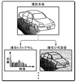
- FIG. 13 is a schematic view illustrating a process of calculating a focused shadow area in a captured image of a vehicle peripheral area and performing luminance adjustment on the captured image so that the brightness of the focused shadow area may be appropriately increased. It is an explanatory view explaining an example of luminance characteristic data. It is an explanatory view explaining an example of luminance characteristic data. It is a functional block diagram of the brightness adjustment function in the preferred embodiment of the in-vehicle camera device according to the present invention. It is a flowchart which shows the flow of the brightness adjustment in the vehicle-mounted camera apparatus by FIG.
- the luminance adjustment of the entire photographed image is performed based on the luminance characteristic data of the partial region which is the region excluding the vehicle in the generated photographed image of the peripheral region of the vehicle. For example, using a pixel value (luminance value) of a pure vehicle peripheral area except for a vehicle component such as a bumper of the own vehicle in a captured image, a shadow area such as a shadow in the vehicle peripheral area is brightened. Thereby, the visibility of the vehicle peripheral image displayed on the monitor is improved.
- the luminance of the entire photographed image is increased based on the luminance characteristic data of a specific shadow area of interest in the photographed image.
- a photographed image is generated by the camera unit of the in-vehicle camera device (# 01).
- the camera unit is provided with a normal white balance circuit, a ⁇ correction unit, and the like, and the generated photographed image, to be precise, a digital photographed image is an image of a general quality level. That is, the highlight area, the shadow area, and the middle area are balanced in the photographed image, the whiteout is suppressed in the highlight area, and the blackout is suppressed in the shadow area.
- luminance characteristic data is generated using the luminance values in pixel units (# 02).
- a luminance histogram, a luminance distribution image, etc. may be mentioned.
- the luminance histogram represents the distribution of the luminance (the degree of light and dark) of an image by taking the luminance on the horizontal axis and the number of pixels on the vertical axis. It is possible to detect the ratio of shadow areas and highlight areas in Further, the luminance distribution image represents the distribution of luminance at a predetermined luminance gradation on a secondary coordinate plane equivalent to the photographed image.
- This luminance gradation is not linear, and may be non-linear, with the shadow region important to the present invention as the high gradation.
- the photographed image itself is also a kind of luminance distribution image
- the photographed image itself or its mosaic image may be used as the luminance distribution image.
- an area darkened as a shadow is calculated as the target shadow portion based on such luminance characteristic data.
- the shooting center of the on-vehicle camera is substantially fixed, the upper half of the shooting screen is a bright area (highlight area) such as the sky, and the lower half of the shooting screen is affected by shadows. There is a high possibility of becoming a (shadow area).
- the visibility evaluation may be performed on the captured image based on human perception to generate a visibility evaluation image as luminance characteristic data, and an area with low visibility and a shadow area may be calculated as the target vehicle area.
- learning control such as a neural network. For example, a number of typical captured images are acquired in advance, and a shadow region of interest in each captured image is determined.
- An arithmetic module capable of obtaining an output in which a shadow area is specified by inputting the brightness characteristic data of an input photographed image by using the combination of the shadow area thus obtained and the luminance characteristic data of the photographed image as teacher information. To construct.
- the luminance characteristic data is generated for the entire photographed image, and as shown in FIG. 3, the luminance for each section obtained by dividing the photographed image into a plurality of sections. It can be divided into characteristic data, that is, section luminance characteristic data.
- the segmentation makes it more effective data for calculating the shadow region of interest. For example, it is possible to easily detect the position of a shadow area in which a blackout occurs in a captured image from the section luminance histogram.
- a shadow area in which there is a possibility of the presence of an object on or near the road surface that has become dark due to shadowing is calculated as a shadow area of interest (# 03).
- One of the simplest attention shadow area calculation algorithms is to set a dark area near the road surface surrounded by a bright area upward as the attention shadow area.
- the luminance values of pixels included in areas other than the attention shadow area, the average luminance value of the photographed image, etc. may be obtained based on the luminance values of the pixels included in the attention shadow area. Is also used to calculate the amount of increase in brightness for brightening the shadow area of interest so as to improve the visibility and recognizability of the shadow area of interest (# 04).
- a brightness adjustment is performed to increase the brightness of the captured image based on the calculated amount of brightness increase, but it is generally known that the brightness adjustment (correction) of the captured image is performed as well known. ) It is done using a curve.
- the brightness adjustment curve may be linear (that is, a straight line), but generally an S-shaped curve is used. Through this brightness adjustment, a brightness increase that substantially corresponds to the calculated brightness increase amount is realized in the shadow region of interest.
- the shape of the luminance adjustment curve that is, the degree of luminance increase in the entire captured image may be better to be changed depending on the vehicle area of interest or the luminance distribution of the captured image. Therefore, it is convenient to adopt a configuration in which various brightness adjustment curves are stored in advance and appropriately selected.
- an optimal luminance adjustment curve is selected and set (# 05), and then the luminance adjustment of the captured image is performed using the luminance adjustment curve (# 06).
- this brightness adjustment curve may be tabulated (mapped) in terms of computer processing, or may be constructed by an operation method using an arithmetic expression or the like, but the brightness adjustment curve here is such It is used as a superordinate term that generically refers to all forms.
- the photographed image whose brightness has been adjusted takes in the photographed image and displays it on the monitor (in-vehicle monitor 51) as a peripheral monitoring image or an image that recognizes traveling obstacles such as other cars and pedestrians from the photographed image It is output to the recognition module 6 (# 07).
- the photographed image sent to the photographed image display module 5 is displayed on the monitor (# 08).
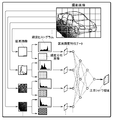
- the on-vehicle camera device includes a camera body 10 including a photographing optical unit 11 and a photographed image generation unit 12 as a functional unit for acquiring a photographed image.
- the photographing optical unit 11 includes optical system components such as a lens, an aperture and a shutter, and the photographed image generation unit 12 includes a photographing element such as a CCD and a CMOS.
- the luminance-adjusted photographed image output from the in-vehicle camera device detects the photographed image display module 5 that generates a display image for the in-vehicle monitor 51, or detects an obstacle around the vehicle, a road sign, a parking lot or the like.
- Image recognition module 6 or both.
- different luminance adjustment methods may be used in the luminance adjustment module 3 for the photographed image sent to the photographed image display module 5 and the photographed image sent to the image recognition module 6, the basic principle will be described with reference to FIG. It conforms to what was done.
- the various functions included in the brightness adjustment module 3 are substantially created by activating a program installed in the computer system and work in cooperation with the computer system hardware.
- the luminance adjustment module 3 in this embodiment is a functional unit particularly related to the present invention, such as a photographed image input unit 31, a luminance characteristic data generation unit 32, a shadow area calculation unit 33, a luminance increase amount calculation unit 34, and a luminance adjustment curve.
- a setting unit 35, a brightness adjustment curve table 36, a brightness adjustment unit 37, and a photographed image output unit 38 are provided.
- the photographed image input unit 31 temporarily develops the photographed image sent from the photographed image generation unit 12 in the memory.
- the luminance characteristic data generation unit 32 generates luminance characteristic data such as a luminance histogram and a luminance distribution image from the photographed image expanded in the memory.
- the luminance characteristic data generation unit 32 of this embodiment is provided with a function of dividing a photographed image into a plurality of sections and generating luminance characteristic data from each section. In this division, it is convenient to clearly separate the area in which the sky may appear and the area in which the road surface may appear. This is because it is preferable to divide the sky area and the road surface area as much as possible since the important area for the brightness adjustment module 3 is an area that is darkened behind a certain shadow near the road surface.
- the shadow area calculation unit 33 calculates a target shadow area based on a predetermined rule (condition) using the luminance characteristic data generated by the luminance characteristic data generation unit 32 as an input parameter.
- the target shadow area is an area that is important for a peripheral image for monitoring the periphery of a vehicle, and in an ordinary captured image, it is an area that enters a shadow of a vehicle or a building and becomes dark.
- an operation unit constructed using learning such as neural networks. Then the calculation accuracy will improve.
- the brightness increase amount calculation unit 34 calculates the brightness increase amount such that blackening in the target shadow region is suppressed to some extent using the calculated brightness data of the target shadow region, for example, the average brightness value and the middle brightness value. Do. At that time, a configuration may be adopted in which the luminance value outside the target shadow area is taken into consideration.
- a plurality of luminance adjustment curves are prepared in the luminance adjustment curve table 36 to be used when adjusting the luminance of the entire photographed image based on the amount of luminance increase. Therefore, the brightness adjustment curve setting unit 35 selects an optimum brightness adjustment curve from the brightness adjustment curve table 36 based on the brightness increase amount, the brightness characteristic data of the photographed image, and the like. Since the selected brightness adjustment curve is set for the brightness adjustment unit 37, the brightness adjustment unit 37 uses the set brightness adjustment curve to adjust the brightness of the photographed image.
- the photographed image output unit 38 outputs the luminance-adjusted photographed image to the photographed image display module 5 and / or the image recognition module 6.
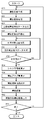
- the photographed image is generated by the camera body 10 (# 20) and expanded in the memory of the luminance adjustment module 3 (# 22).
- the photographed image expanded in the memory the whole area luminance characteristic data obtained from the whole is generated by the luminance characteristic data generation unit 32 (# 24).
- division is set to a plurality of sections for the photographed image (# 26). Processing target sections are designated sequentially from the divided sections (# 28), and luminance characteristic data of the sections are generated (# 30).
- the whole area luminance characteristic data and the section luminance characteristic data A shadow area of interest is calculated by the shadow area calculation unit 33 as an input parameter (# 34). Further, the brightness increase amount calculating unit 34 calculates the brightness increase amount necessary for making the image of the focus shadow region clearer based on the brightness of the focus shadow region (# 36). When the brightness adjustment curve is set based on the calculated brightness increase amount (# 38), the brightness adjustment unit 37 performs the brightness adjustment on the photographed image (# 40). The photographed image whose luminance has been adjusted is output through the photographed image output unit 38 (# 42). This series of processing steps is repeatedly executed until the vehicle periphery monitoring process is completed (# 44 Yes branch).
- the brightness increase amount is calculated each time a captured image is acquired, but it is not necessary to calculate the brightness increase amount each time.
- the brightness increase amount may be calculated at a predetermined time interval, a predetermined number of sheets, or every scene change.
- many captured images are subjected to the brightness adjustment by using the previously used brightness adjustment curve as it is, and the calculation load of the brightness adjustment is reduced.
- the configuration of the brightness adjustment module 3 is finely divided into functional blocks for easy understanding of the process of adjusting the brightness of the photographed image.
- this functional block is for the purpose of illustration and the present invention It is not necessarily limited to such a block configuration.
- the functional blocks may take various forms, as long as the described functions can be realized. For example, if the brightness increase amount is calculated, the brightness adjustment curve setting unit 35 becomes unnecessary in the case where the brightness adjustment curve is automatically set based on the brightness increase amount. (3) In the embodiment described above, the luminance histogram accompanied by statistical calculation is used as the luminance characteristic data, but when adopting a simple configuration in which a shadow area not more than a predetermined luminance value is calculated, luminance characteristic data is generated The unit 32 and the shadow area calculation unit 33 are integrated.
- the present invention is applicable to all systems that monitor the surroundings of a vehicle using captured images.
Landscapes
- Engineering & Computer Science (AREA)
- Multimedia (AREA)
- Physics & Mathematics (AREA)
- General Physics & Mathematics (AREA)
- Theoretical Computer Science (AREA)
- Signal Processing (AREA)
- Mechanical Engineering (AREA)
- Closed-Circuit Television Systems (AREA)
- Studio Devices (AREA)
- Image Processing (AREA)
- Fittings On The Vehicle Exterior For Carrying Loads, And Devices For Holding Or Mounting Articles (AREA)
- Image Analysis (AREA)
Priority Applications (2)
| Application Number | Priority Date | Filing Date | Title |
|---|---|---|---|
| EP12800299.5A EP2723060A4 (en) | 2011-06-16 | 2012-05-18 | VEHICLE MOUNTED CAMERA DEVICE |
| US14/116,451 US20140085473A1 (en) | 2011-06-16 | 2012-05-18 | In-vehicle camera apparatus |
Applications Claiming Priority (2)
| Application Number | Priority Date | Filing Date | Title |
|---|---|---|---|
| JP2011-134465 | 2011-06-16 | ||
| JP2011134465A JP5435307B2 (ja) | 2011-06-16 | 2011-06-16 | 車載カメラ装置 |
Publications (1)
| Publication Number | Publication Date |
|---|---|
| WO2012172922A1 true WO2012172922A1 (ja) | 2012-12-20 |
Family
ID=47356916
Family Applications (1)
| Application Number | Title | Priority Date | Filing Date |
|---|---|---|---|
| PCT/JP2012/062845 Ceased WO2012172922A1 (ja) | 2011-06-16 | 2012-05-18 | 車載カメラ装置 |
Country Status (4)
| Country | Link |
|---|---|
| US (1) | US20140085473A1 (enExample) |
| EP (1) | EP2723060A4 (enExample) |
| JP (1) | JP5435307B2 (enExample) |
| WO (1) | WO2012172922A1 (enExample) |
Cited By (1)
| Publication number | Priority date | Publication date | Assignee | Title |
|---|---|---|---|---|
| EP2843937A1 (en) * | 2013-07-16 | 2015-03-04 | Connaught Electronics Ltd. | Method for adapting a gamma curve of a camera system of a motor vehicle, camera system and motor vehicle |
Families Citing this family (14)
| Publication number | Priority date | Publication date | Assignee | Title |
|---|---|---|---|---|
| JP6620762B2 (ja) * | 2015-02-12 | 2019-12-18 | ソニー株式会社 | 画像処理装置、画像処理方法、プログラムおよび画像処理システム |
| EP3190784A4 (en) * | 2015-11-19 | 2018-04-11 | Streamax Technology Co., Ltd. | Method and apparatus for switching region of interest |
| US20170147887A1 (en) * | 2015-11-23 | 2017-05-25 | Ford Global Technologies, Llc | Method and apparatus for interior/exterior vehicular environment alerts |
| JP6589741B2 (ja) | 2016-05-25 | 2019-10-16 | 株式会社デンソー | 画像処理装置 |
| US10861138B2 (en) * | 2016-07-13 | 2020-12-08 | Rakuten, Inc. | Image processing device, image processing method, and program |
| JP2018056743A (ja) * | 2016-09-28 | 2018-04-05 | ルネサスエレクトロニクス株式会社 | 逆光補正プログラム及び半導体装置 |
| JP2020104804A (ja) * | 2018-12-28 | 2020-07-09 | トヨタ自動車株式会社 | 電子ミラーシステム |
| WO2022012748A1 (en) * | 2020-07-15 | 2022-01-20 | Veoneer Sweden Ab | Vision system for a motor vehicle |
| JP2022038136A (ja) * | 2020-08-26 | 2022-03-10 | トヨタ自動車株式会社 | ルート決定システム、ルート決定方法及びルート決定プログラム |
| DE102020213270A1 (de) | 2020-10-21 | 2022-04-21 | Conti Temic Microelectronic Gmbh | System zur Vermeidung von Unfällen durch Wildwechsel bei Dämmerung und Nacht |
| CN113507569A (zh) * | 2021-06-30 | 2021-10-15 | 上海商汤临港智能科技有限公司 | 车载摄像头的控制方法及装置、设备和介质 |
| JP7618603B2 (ja) * | 2022-01-28 | 2025-01-21 | キヤノン株式会社 | カメラシステム、移動体、カメラシステムの制御方法、及びコンピュータプログラム |
| US11935156B2 (en) | 2022-02-18 | 2024-03-19 | GM Global Technology Operations LLC | Methods and systems for color harmonization in surround view systems |
| KR20250145814A (ko) * | 2024-03-29 | 2025-10-13 | 현대자동차주식회사 | 차량용 서라운드뷰 모니터링 장치 및 방법 |
Citations (6)
| Publication number | Priority date | Publication date | Assignee | Title |
|---|---|---|---|---|
| JP2001034748A (ja) * | 1999-07-26 | 2001-02-09 | Nippon Telegr & Teleph Corp <Ntt> | 画像補正方法及びその装置及びその方法を記録した記録媒体及びその装置を組み込んだ画像撮影装置及びその装置を組み込んだ画像表示装置 |
| JP2007074070A (ja) * | 2005-09-05 | 2007-03-22 | Auto Network Gijutsu Kenkyusho:Kk | 車両周辺視認装置 |
| JP2007272421A (ja) | 2006-03-30 | 2007-10-18 | Toyota Central Res & Dev Lab Inc | 対象物検出装置、方法及びプログラム |
| JP2008277921A (ja) * | 2007-04-25 | 2008-11-13 | Sharp Corp | 撮像装置およびこれを備えた移動体 |
| JP2010050568A (ja) * | 2008-08-19 | 2010-03-04 | Ricoh Co Ltd | 画像処理装置、画像処理方法、プログラムおよび記録媒体 |
| JP2010208372A (ja) | 2009-03-06 | 2010-09-24 | Toyota Motor Corp | 輝度調整装置 |
Family Cites Families (6)
| Publication number | Priority date | Publication date | Assignee | Title |
|---|---|---|---|---|
| US7576767B2 (en) * | 2004-07-26 | 2009-08-18 | Geo Semiconductors Inc. | Panoramic vision system and method |
| US7486835B2 (en) * | 2005-03-17 | 2009-02-03 | Delphi Technologies, Inc. | System and method for enhancing an image |
| US8014034B2 (en) * | 2005-04-13 | 2011-09-06 | Acd Systems International Inc. | Image contrast enhancement |
| JP4321543B2 (ja) * | 2006-04-12 | 2009-08-26 | トヨタ自動車株式会社 | 車両周辺監視装置 |
| JP4987573B2 (ja) * | 2007-06-01 | 2012-07-25 | 富士重工業株式会社 | 車外監視装置 |
| TWI368185B (en) * | 2008-11-06 | 2012-07-11 | Ind Tech Res Inst | Method for detecting shadow of object |
-
2011
- 2011-06-16 JP JP2011134465A patent/JP5435307B2/ja not_active Expired - Fee Related
-
2012
- 2012-05-18 WO PCT/JP2012/062845 patent/WO2012172922A1/ja not_active Ceased
- 2012-05-18 EP EP12800299.5A patent/EP2723060A4/en not_active Withdrawn
- 2012-05-18 US US14/116,451 patent/US20140085473A1/en not_active Abandoned
Patent Citations (6)
| Publication number | Priority date | Publication date | Assignee | Title |
|---|---|---|---|---|
| JP2001034748A (ja) * | 1999-07-26 | 2001-02-09 | Nippon Telegr & Teleph Corp <Ntt> | 画像補正方法及びその装置及びその方法を記録した記録媒体及びその装置を組み込んだ画像撮影装置及びその装置を組み込んだ画像表示装置 |
| JP2007074070A (ja) * | 2005-09-05 | 2007-03-22 | Auto Network Gijutsu Kenkyusho:Kk | 車両周辺視認装置 |
| JP2007272421A (ja) | 2006-03-30 | 2007-10-18 | Toyota Central Res & Dev Lab Inc | 対象物検出装置、方法及びプログラム |
| JP2008277921A (ja) * | 2007-04-25 | 2008-11-13 | Sharp Corp | 撮像装置およびこれを備えた移動体 |
| JP2010050568A (ja) * | 2008-08-19 | 2010-03-04 | Ricoh Co Ltd | 画像処理装置、画像処理方法、プログラムおよび記録媒体 |
| JP2010208372A (ja) | 2009-03-06 | 2010-09-24 | Toyota Motor Corp | 輝度調整装置 |
Non-Patent Citations (1)
| Title |
|---|
| See also references of EP2723060A4 |
Cited By (1)
| Publication number | Priority date | Publication date | Assignee | Title |
|---|---|---|---|---|
| EP2843937A1 (en) * | 2013-07-16 | 2015-03-04 | Connaught Electronics Ltd. | Method for adapting a gamma curve of a camera system of a motor vehicle, camera system and motor vehicle |
Also Published As
| Publication number | Publication date |
|---|---|
| US20140085473A1 (en) | 2014-03-27 |
| EP2723060A1 (en) | 2014-04-23 |
| JP2013005234A (ja) | 2013-01-07 |
| JP5435307B2 (ja) | 2014-03-05 |
| EP2723060A4 (en) | 2014-07-02 |
Similar Documents
| Publication | Publication Date | Title |
|---|---|---|
| JP5435307B2 (ja) | 車載カメラ装置 | |
| JP2013005234A5 (enExample) | ||
| JP5071198B2 (ja) | 信号機認識装置,信号機認識方法および信号機認識プログラム | |
| US9424462B2 (en) | Object detection device and object detection method | |
| JP5437855B2 (ja) | 障害物検知装置およびそれを備えた障害物検知システム、並びに障害物検知方法 | |
| US8896625B2 (en) | Method and system for fusing images | |
| US11477372B2 (en) | Image processing method and device supporting multiple modes and improved brightness uniformity, image conversion or stitching unit, and computer readable recording medium realizing the image processing method | |
| JP4389999B2 (ja) | 露出制御装置及び露出制御プログラム | |
| KR101367637B1 (ko) | 감시장치 | |
| WO2012067028A1 (ja) | 画像入力装置および画像処理装置 | |
| JP2010257282A (ja) | 障害物検知装置、および当該装置を搭載した車両 | |
| JP6246629B2 (ja) | 監視装置 | |
| WO2011000392A1 (en) | Method and camera system for improving the contrast of a camera image | |
| EP2843937B1 (en) | Method for adapting a gamma curve of a camera system of a motor vehicle, camera system and motor vehicle | |
| JP2008135856A (ja) | 物体認識装置 | |
| JP6266022B2 (ja) | 画像処理装置、警報装置、および画像処理方法 | |
| JP6289439B2 (ja) | 画像処理装置 | |
| TWI630818B (zh) | Dynamic image feature enhancement method and system | |
| JP2019204988A (ja) | 画像処理装置及び画像処理方法 | |
| JP2006060504A (ja) | 白線検出用カメラの露出制御装置 | |
| KR101909392B1 (ko) | 서라운드 뷰 모니터링 시스템 | |
| CN116567201B (en) | Defocus detection method, device, equipment and storage medium | |
| CN120840502A (zh) | 一种车辆控制方法、装置及车辆 | |
| JP2019129469A (ja) | 画像処理装置 | |
| CN114140763A (zh) | 障碍物感知方法、装置、设备及存储介质 |
Legal Events
| Date | Code | Title | Description |
|---|---|---|---|
| 121 | Ep: the epo has been informed by wipo that ep was designated in this application |
Ref document number: 12800299 Country of ref document: EP Kind code of ref document: A1 |
|
| WWE | Wipo information: entry into national phase |
Ref document number: 14116451 Country of ref document: US |
|
| WWE | Wipo information: entry into national phase |
Ref document number: 2012800299 Country of ref document: EP |
|
| NENP | Non-entry into the national phase |
Ref country code: DE |