WO2012172833A1 - 工作機械 - Google Patents
工作機械 Download PDFInfo
- Publication number
- WO2012172833A1 WO2012172833A1 PCT/JP2012/054510 JP2012054510W WO2012172833A1 WO 2012172833 A1 WO2012172833 A1 WO 2012172833A1 JP 2012054510 W JP2012054510 W JP 2012054510W WO 2012172833 A1 WO2012172833 A1 WO 2012172833A1
- Authority
- WO
- WIPO (PCT)
- Prior art keywords
- workpiece
- machine tool
- measuring
- tool
- saddle
- Prior art date
- Legal status (The legal status is an assumption and is not a legal conclusion. Google has not performed a legal analysis and makes no representation as to the accuracy of the status listed.)
- Ceased
Links
Images




Classifications
-
- B—PERFORMING OPERATIONS; TRANSPORTING
- B23—MACHINE TOOLS; METAL-WORKING NOT OTHERWISE PROVIDED FOR
- B23Q—DETAILS, COMPONENTS, OR ACCESSORIES FOR MACHINE TOOLS, e.g. ARRANGEMENTS FOR COPYING OR CONTROLLING; MACHINE TOOLS IN GENERAL CHARACTERISED BY THE CONSTRUCTION OF PARTICULAR DETAILS OR COMPONENTS; COMBINATIONS OR ASSOCIATIONS OF METAL-WORKING MACHINES, NOT DIRECTED TO A PARTICULAR RESULT
- B23Q17/00—Arrangements for observing, indicating or measuring on machine tools
- B23Q17/20—Arrangements for observing, indicating or measuring on machine tools for indicating or measuring workpiece characteristics, e.g. contour, dimension, hardness
-
- B—PERFORMING OPERATIONS; TRANSPORTING
- B23—MACHINE TOOLS; METAL-WORKING NOT OTHERWISE PROVIDED FOR
- B23Q—DETAILS, COMPONENTS, OR ACCESSORIES FOR MACHINE TOOLS, e.g. ARRANGEMENTS FOR COPYING OR CONTROLLING; MACHINE TOOLS IN GENERAL CHARACTERISED BY THE CONSTRUCTION OF PARTICULAR DETAILS OR COMPONENTS; COMBINATIONS OR ASSOCIATIONS OF METAL-WORKING MACHINES, NOT DIRECTED TO A PARTICULAR RESULT
- B23Q17/00—Arrangements for observing, indicating or measuring on machine tools
- B23Q17/22—Arrangements for observing, indicating or measuring on machine tools for indicating or measuring existing or desired position of tool or work
-
- B—PERFORMING OPERATIONS; TRANSPORTING
- B23—MACHINE TOOLS; METAL-WORKING NOT OTHERWISE PROVIDED FOR
- B23Q—DETAILS, COMPONENTS, OR ACCESSORIES FOR MACHINE TOOLS, e.g. ARRANGEMENTS FOR COPYING OR CONTROLLING; MACHINE TOOLS IN GENERAL CHARACTERISED BY THE CONSTRUCTION OF PARTICULAR DETAILS OR COMPONENTS; COMBINATIONS OR ASSOCIATIONS OF METAL-WORKING MACHINES, NOT DIRECTED TO A PARTICULAR RESULT
- B23Q17/00—Arrangements for observing, indicating or measuring on machine tools
- B23Q17/22—Arrangements for observing, indicating or measuring on machine tools for indicating or measuring existing or desired position of tool or work
- B23Q17/2233—Arrangements for observing, indicating or measuring on machine tools for indicating or measuring existing or desired position of tool or work for adjusting the tool relative to the workpiece
-
- B—PERFORMING OPERATIONS; TRANSPORTING
- B23—MACHINE TOOLS; METAL-WORKING NOT OTHERWISE PROVIDED FOR
- B23Q—DETAILS, COMPONENTS, OR ACCESSORIES FOR MACHINE TOOLS, e.g. ARRANGEMENTS FOR COPYING OR CONTROLLING; MACHINE TOOLS IN GENERAL CHARACTERISED BY THE CONSTRUCTION OF PARTICULAR DETAILS OR COMPONENTS; COMBINATIONS OR ASSOCIATIONS OF METAL-WORKING MACHINES, NOT DIRECTED TO A PARTICULAR RESULT
- B23Q17/00—Arrangements for observing, indicating or measuring on machine tools
- B23Q17/24—Arrangements for observing, indicating or measuring on machine tools using optics or electromagnetic waves
Definitions
- the present invention relates to a machine tool that automatically measures the processing position, shape, inclination angle, and distance to the processing position of a workpiece.
- a workpiece in a machine tool, can be machined by relatively moving a tool mounted on a spindle and a workpiece attached to a table in the horizontal direction and the vertical direction.
- a mounting failure on the workpiece or a shape failure on the workpiece there is a risk that uncut material will be left on the workpiece after machining, or that a large machining load will act on the workpiece and tool being machined. There is.
- the coordinates of the designated location on the workpiece are measured using a probe attached to the spindle.
- the probe attached to the spindle in this way, not only the work of attaching the probe to the spindle is required for each workpiece to be processed, but also the work of exchanging the spindle between the probe and the tool is required. It becomes necessary.
- the measurement method using a probe when the probe is brought into contact with the workpiece, the approach speed of the probe to the workpiece needs to be kept low in order to prevent the probe from being overloaded. As a result, in the conventional machine tool, it takes more time than necessary to measure the workpiece.
- the present invention solves the above-described problems, and provides a machine tool capable of measuring a workpiece easily and in a short time and machining the workpiece with high accuracy. For the purpose.
- a machine tool that solves the above problems is as follows.
- a saddle that rotatably supports the main shaft and is supported so as to be movable at least in the vertical direction;
- Measuring means for measuring the processing position, shape, inclination angle and distance to the processing position of the workpiece in a non-contact manner;
- a conveying means provided on the saddle, and conveying the measuring means between a measuring position at which the measuring means can measure the workpiece and a retracted position retracted from the measuring position; After determining whether or not the workpiece has a mounting defect or a shape defect based on the processing position, shape, inclination angle, and distance to the processing position of the workpiece measured by the measuring means
- a control means for controlling movement of at least one of the tool and the workpiece in accordance with the determination result.
- a machine tool that solves the above problems is as follows.
- a machine tool for processing a workpiece with the tool by relatively moving a spindle on which a tool can be mounted and a workpiece in a horizontal direction and a vertical direction A table to which the work piece is detachably attached and supported so as to be movable in the horizontal direction;
- Measuring means for measuring the processing position, shape, inclination angle and distance to the processing position of the workpiece in a non-contact manner;
- Provided on the main shaft side facing the moving range of the workpiece supports the measuring means so as to be movable in the vertical direction, and retracts from the measuring position where the measuring means can measure the workpiece and the measuring position.
- Transport means for transporting between the retracted position, After determining whether or not the workpiece has a mounting defect or a shape defect based on the processing position, shape, inclination angle, and distance to the processing position of the workpiece measured by the measuring means And a control means for controlling movement of at least one of the tool and the workpiece in accordance with the determination result.
- a machine tool that solves the above problems is as follows.
- a saddle that rotatably supports the spindle;
- a column for supporting the saddle in the vertical direction;
- the conveying means is provided in the column.
- a machine tool that solves the above problems is as follows.
- a saddle that rotatably supports the spindle;
- a column for supporting the saddle in the vertical direction;
- the conveying means is provided on a floor surface supporting the column.
- the conveying means conveys the measuring means in the axial direction of the main shaft between the measurement position and the retracted position.
- a machine tool that solves the above problems is as follows.
- the conveying means is provided so as to face in the thickness direction of the workpiece,
- the measuring means attached to each of the opposed conveying means measures the processing position, shape, inclination angle, and distance to the processing position of the workpiece from both sides in the thickness direction of the workpiece. It is characterized by that.
- the measuring device for measuring the workpiece in a non-contact manner is provided with the conveying device for conveying the measuring device between the measuring position and the retracted position.
- the conveying device for conveying the measuring device between the measuring position and the retracted position.
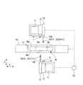
- FIG. 1 is a schematic configuration diagram of a machine tool according to a first embodiment of the present invention. It is the principal part enlarged view of FIG. 1, Comprising: It is the figure which showed the state provided with one conveying apparatus.
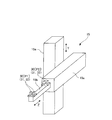
- 1 is a block diagram illustrating a configuration of a machine tool according to a first embodiment of the present invention. It is the principal part enlarged view of FIG. 1, Comprising: It is the figure which showed the state provided with two or more conveying apparatuses. It is a top view when the machine tool which concerns on 1st Example of this invention is made to oppose. It is a schematic block diagram of the machine tool which concerns on 2nd Example of this invention. It is the figure which showed an example of the conveying apparatus provided in the machine tool which concerns on 2nd Example of this invention.
- a column 11 is erected on the machine tool 1.
- a saddle 12 is supported on the side surface of the column 11 so as to be movable up and down in the vertical direction (hereinafter referred to as the Y-axis direction).
- a spindle head 13 is supported in the saddle 12 so as to be movable in the horizontal direction (hereinafter referred to as the Z-axis direction).
- the spindle 14 is arranged in the axial direction (Z-axis direction). And is supported rotatably about its axis.
- a tool T is detachably mounted on the tip of the main shaft 14. Further, a side surface of the saddle 12 is provided with a transport device (transport means) 15 as will be described in detail later.
- the machine tool 1 is provided with a table bed 16 on the front surface of the column 11, and a table 17 is movable on the upper surface of the table bed 16 in the horizontal direction (hereinafter referred to as the X-axis direction). It is supported.
- a work (workpiece) W is detachably attached to the upper surface of the table 17.
- the tool T and the transport device 15 can be moved in the Y-axis direction. Further, by driving the spindle head 13, the spindle 14 and the tool T can be moved in the axial direction as the spindle head 13 moves in the Z-axis direction. Furthermore, by driving the main shaft 14, the tool T can be moved in the axial direction as the main shaft 14 moves in the Z-axis direction. On the other hand, by driving the table 17, the workpiece W can be moved in the X-axis direction together with the table 17.
- the transport device 15 includes a device main body 15a, a transport rod 15b, a motor 15c, and an amplifier 15d.
- the apparatus main body 15a is attached to the side surface of the saddle 12, and the transport rod 15b can slide in the Z-axis direction within the apparatus main body 15a, that is, can be extended so as to approach and separate from the workpiece W. It is supported by. Therefore, the conveyance rod 15b can be moved in the Z-axis direction by driving the motor 15c.
- a workpiece measuring device (measuring means) 30 is attached to the tip of the transport rod 15b. Prior to machining the workpiece W, the workpiece measuring device 30 measures the machining position (coordinates of the machining site), the shape (dimensions of the machining site), the inclination angle (the machining allowance), and the workpiece measurement.
- This is a non-contact type measuring device that measures the distance from the tool 30 to the processing position in a non-contact manner.
- a CCD camera 31 or a laser length measuring device 32 is employed as the workpiece measuring device 30.
- FIG. 1 shows a state in which one work measuring instrument 30 is attached to the tip of the transport rod 15b.
- two work measuring instruments 30 are attached to the tip of the transport rod 15b. Shows the state.
- the image data is acquired by imaging a predetermined imaging region on the workpiece W by the CCD camera 31. The Then, the image data is input to the analysis device 19 via the controller 33. Further, the analysis device 19 recognizes the input image data as the shape of the workpiece W, and then outputs it to the NC device 20 described later.
- the workpiece measuring device 30 is a laser length measuring device 32
- a predetermined irradiation point on the workpiece W is irradiated with the laser light output from the laser length measuring device 32 as shown in FIG.
- the measurement distance is input to the analysis device 19 via the controller 33.
- the analysis device 19 outputs the input measurement distance as it is as a distance to the machining position to the NC device 20 described later, and also recognizes it as the shape of the workpiece W, and then outputs it to the NC device 20.
- the transport device 15 can be moved relative to the workpiece W in the X-axis direction and the Y-axis direction. That is, the conveyance device 15 can be positioned at a position facing a predetermined imaging region and a predetermined irradiation point on the workpiece W. Further, the workpiece measuring device 30 (the CCD camera 31 and the CCD camera 31) is mounted in a state where the tool T is mounted on the main shaft 14 by driving the positioned conveying device 15 and sliding the conveying rod 15b in the Z-axis direction.
- the laser length measuring device 32 is transported between a measurement position (capturing position and irradiation position) P1 at which the workpiece W can be measured (capturing and irradiating) and a retracted position P2 retracted from the measuring position P1. be able to.
- the measurement position P1 is set to a position (a position closer to the workpiece W) that is fed out of the tip position of the tool T mounted on the spindle 14 in the Z-axis direction.
- the retracted position P2 is set to a retracted position (a position away from the workpiece W) rather than a tip position of the tool T mounted on the main shaft 14 in the Z-axis direction.
- the machine tool 1 is provided with an NC device (control means) 20 for controlling the machine tool 1 in an integrated manner.
- an NC device control means
- a saddle 12, a spindle head 13, a spindle 14, a transport device 15, a table 17, an analysis device 19, a work measuring instrument 30, etc. are connected to the NC device 20.
- the movement in the Y-axis direction and the Z-axis direction and the movement in the X-axis direction of the workpiece W attached to the table 17 are controlled.
- the machining operation by the transfer device 15 and the workpiece measuring instrument 30 is controlled before machining by the tool T, and the machining position, shape, inclination angle and workpiece machining of the workpiece W are machined from the workpiece measuring instrument 30. The distance to the position is measured.
- the analysis device 19, the NC device 20, the workpiece measuring device 30, the CCD camera 31, the laser length measuring device 32, etc. constitute measuring means.
- pilot holes Wc serving as a plurality of through holes are processed in advance.
- the conveying rod 15b is extended.
- the CCD camera 31 and the laser length measuring device 32 are conveyed from the retracted position P2 to the measuring position P1.
- the analysis device 19 calculates the center and inner diameter of the pilot hole Wc based on the input image data.
- the analyzer 19 calculates the inclination angle of the side surface Wa and the distance to the end surface of the lower hole Wc based on the plurality of input measurement distances. As described above, when the laser length measuring device 32 is used, the distance measurement by the laser length measuring device 32 is performed at least twice.
- the NC device 20 based on the input center and inner diameter of the lower hole Wc, the inclination angle of the side surface Wa, the distance to the end surface of the lower hole Wc, whether or not the work W has a mounting failure, and Then, it is determined whether or not the workpiece W has a shape defect.
- the tool T is moved in the Y-axis direction and the Z-axis based on preset machining conditions.
- predetermined machining is performed on the prepared hole Wc of the workpiece W and the end surface of the prepared hole Wc.
- the center and inner diameter of the pilot hole Wc, the inclination angle of the side surface Wa, and the lower hole Wc Based on the distance to the end face, the movement of the tool T in the Y-axis direction and the Z-axis direction and the movement of the workpiece W in the X-axis direction are corrected.
- the attachment position of the workpiece W is corrected, and the pilot hole Wc of the workpiece W is corrected.
- a predetermined process is performed with respect to the pilot hole Wc.
- one transport device 15 is provided on the side surface of the saddle 12, but a plurality of transport devices 15 may be provided.
- the work measuring instrument 30 in one transport device 15 is a CCD camera 31, and the other The workpiece measuring device 30 in the transport device 15 is a laser length measuring device 32.
- part of the CCD camera 31 and the irradiation point of the laser length measuring device 32 can be set to a separate position.
- the machine tool 1 provided with the one column 11 is employ
- shown in FIG. 17 may be a machine tool arranged to face the workpiece W in the thickness direction.
- the workpiece measuring instrument 30 attached to the conveying device 15 on the side surface Wa side causes the pilot hole Wc to open to the side surface Wa.
- the center and inner diameter, the inclination angle of the side surface Wa, and the distance to the end face of the pilot hole Wc that opens to the side surface Wa are measured, and the workpiece measuring device 30 attached to the conveying device 15 on the side surface Wb opens the side Wb.
- the center and inner diameter of the lower hole Wc, the inclination angle of the side surface Wb, and the distance to the end surface of the lower hole Wc opening in the side surface Wb are measured.
- the workpiece measuring instrument 30 attached to each of the opposed conveying devices 15 allows the center and inner diameter of the lower hole Wc, the inclination angles of the side surfaces Wa and Wb, and the end surface of the lower hole Wc from both sides in the thickness direction of the workpiece W. Can be measured simultaneously, so that the workpiece W can be measured with high accuracy in a short time.
- the column 11 is fixed, but it may be moved in the X-axis direction and the Z-axis direction.
- the center and inner diameter of the lower hole Wc, the side surfaces Wa and Wb are provided by providing the transport device 15 for transporting the non-contact type work measuring instrument 30 on the side surface of the saddle 12. And the distance to the end face of the lower hole Wc can be measured easily and in a short time. Then, based on the above four measurement results by the workpiece measuring instrument 30, it is determined whether or not the workpiece W has a mounting defect and a shape defect, and the movement of the tool T and the workpiece W is controlled according to the determination result. Thus, the workpiece W can be processed with high accuracy.
- the measurement position P1 can be as close as possible to the workpiece W. 30 measurement accuracy can be improved.
- the retracted position P2 can be as far as possible from the workpiece W, it is possible to prevent the workpiece measuring instrument 30 from being damaged or broken down by chips or cutting oil scattered by machining.
- the center and inner diameter of the lower hole Wc, the inclination angles of the side surfaces Wa and Wb, and the distance to the end surface of the lower hole Wc from both the side surface Wa side and the side surface Wb side of the workpiece W are simultaneously determined. By measuring, the measurement time can be further shortened.
- the machine tool 2 is provided with a column bed 41, and a column 42 is supported on the upper surface of the column bed 41 so as to be movable in the X-axis direction. Further, the saddle 12 is supported on the inner surface of the column 42 so as to be movable up and down in the Y-axis direction.
- the conveying devices (conveying means) 15 and 45 shown in FIGS. 7 and 8A and 8B can be attached to the attachment positions H1 and H2.
- the attachment position H1 indicates the position when the conveying devices 15 and 45 are attached to the side surface of the column 42
- the attachment position H2 indicates that the conveying devices 15 and 45 are attached to one end side of the column bed 41 on the floor surface F. Indicates the position.
- the transfer devices 15 and 45 attached to the tool T and the attachment position H1 can be moved in the X-axis direction.
- the transport device 15 includes a support member 15e in addition to the device main body 15a, the transport rod 15b, the motor 15c, and the amplifier 15d described above.
- the support member 15e is attached to the side surface of the column 42 when the transport device 15 is attached to the attachment position H1, and is attached to the floor surface F when the transport device 15 is attached to the attachment position H2.
- the apparatus main body 15a is supported to be movable up and down in the Y-axis direction.
- the workpiece measuring instrument 30 attached to the tip of the transport rod 15b can be moved in the Y-axis direction, and the measurement position P1 and the retreat position P2 in the Z-axis direction Can be transported between.
- the transfer device 45 includes a device main body 45a, a first transfer arm 45b, a second transfer arm 45c, a connecting shaft 45d, a motor 15c, and an amplifier 15d.
- the main body 45a is attached to the side surface of the column 42 when the transport device 45 is attached to the attachment position H1, and the bottom surface is attached to the floor surface F when the transport device 45 is attached to the attachment position H2. It is supposed to be
- the base end of the first transfer arm 45b is rotatably supported on the apparatus main body 45a via a connecting shaft 45d, and the tip of the first transfer arm 45b is connected to the tip of the first transfer arm 45b via the connecting shaft 45d.
- the base end of the second transfer arm 45c is rotatably supported.
- a workpiece measuring instrument 30 is attached to the tip of the second transfer arm 45c.
- the work measuring instrument attached to the tip of the second transfer arm 45c is driven by driving the motor 15c and rotating the first transfer arm 45b and the second transfer arm 45c about the two connecting shafts 45d.
- 30 can be moved in the Y-axis direction and can be transported between the measurement position P1 and the retracted position P2 in the Z-axis direction.
- the machine tool 2 is provided with an NC device 20 that controls the machine tool 2 in an integrated manner.
- an NC device 20 that controls the machine tool 2 in an integrated manner.
- a saddle 12, a spindle head 13, a spindle 14, conveying devices 15 and 45, a table 17, an analysis device 19, a workpiece measuring instrument 30, a column 42, and the like are connected to the NC device 20.
- the measurement operation by the transfer devices 15 and 45 and the workpiece measuring device 30 is controlled, and the machining position, shape, inclination angle, and workpiece measuring device 30 of the workpiece W are controlled.
- the distance from the machining position to the machining position is measured.
- it is determined whether or not the workpiece W has a mounting defect and a shape defect is controlled according to the determination result. In order to make uniform the machining allowance.
- the transport device 15 when the transport device 15 is attached to the attachment position H1, the transport device 15, the table 17, and the column 42 are driven. On the other hand, when the transport device 15 is attached to the attachment position H2, the transport device 15 and the table 17 are driven. Is moved relative to the workpiece W in the X-axis direction and the Y-axis direction to position the conveyance device 15 at a position facing a predetermined imaging region and a predetermined irradiation point on the workpiece W. Can be made. Furthermore, the workpiece measuring device 30 is moved to the measurement position P1 in a state where the tool T is mounted on the spindle 14 by driving the positioned transfer device 15 and sliding the transfer rod 15b in the Z-axis direction. And the retracted position P2.
- the transport device 45 When the transport device 45 is attached to the attachment position H1, the transport device 45, the table 17, and the column 42 are driven. On the other hand, when the transport device 45 is attached to the attachment position H2, the transport device 45 and the table 17 are driven. Is moved relative to the workpiece W in the X-axis direction and the Y-axis direction, and positioned at a position facing a predetermined imaging region and a predetermined irradiation point on the workpiece W. Can be made. Further, by driving the transporting device 45 thus positioned and rotating the first transport arm 45b and the second transport arm 45c in the Z-axis direction, the workpiece T is mounted on the main shaft 14 in a state where the tool T is mounted on the main shaft 14. The measuring device 30 can be transported between the measurement position P1 and the retracted position P2.
- the column 42 side facing the movement range in the X-axis direction of the workpiece W that is, the side surface of the column 42 and the floor surface F supporting the column bed 41 is non-contact type.
- the transport devices 15 and 45 for transporting the workpiece measuring instrument 30 the center and inner diameter of the lower hole Wc, the inclination angles of the side surfaces Wa and Wb, and the distance to the end surface of the lower hole Wc can be easily and short. It can be measured in time. Then, based on the above four measurement results by the workpiece measuring instrument 30, it is determined whether or not the workpiece W has a mounting defect and a shape defect, and the movement of the tool T and the workpiece W is controlled according to the determination result.
- the workpiece W can be processed with high accuracy.
- the machine tool 2 including one column 42 is used as a machine tool for processing the workpiece W.
- the workpiece W having the two columns 42 attached to the table 17 is used. It may be a machine tool that is arranged to face in the thickness direction.
- the CCD camera 31 and the laser length measuring device 32 are used as the two workpiece measuring devices 30, respectively.
- only one of the CCD camera 31 and the laser length measuring device 32 may be used.
- the conveying devices 15 and 45 are provided on the machine tool 1 (for example, a horizontal boring machine) in which the main shaft 14 rotates around the horizontal axis. You may make it provide the conveying apparatuses 15 and 45 in the machine tool (for example, portal-type machining center etc.) rotated around a vertical axis.
- the present invention can be applied to a machine tool that prevents uncut material from being generated on a workpiece after machining or a large machining load acting on a workpiece and tool being machined.
Landscapes
- Engineering & Computer Science (AREA)
- Mechanical Engineering (AREA)
- Physics & Mathematics (AREA)
- Optics & Photonics (AREA)
- Machine Tool Sensing Apparatuses (AREA)
- Turning (AREA)
- Automatic Control Of Machine Tools (AREA)
- Numerical Control (AREA)
Abstract
Description
工具を装着可能な主軸と被加工物とを水平方向及び上下方向に相対的に移動させて、被加工物を前記工具により加工する工作機械において、
前記主軸を回転可能に支持すると共に、少なくとも上下方向に移動可能に支持されるサドルと、
被加工物の加工位置、形状、傾斜角度、及び、前記加工位置までの距離を、非接触で測定する測定手段と、
前記サドルに設けられ、前記測定手段を、前記測定手段が被加工物を測定可能な測定位置と当該測定位置から退避した退避位置との間で搬送する搬送手段と、
前記測定手段によって測定された被加工物の加工位置、形状、傾斜角度、及び、前記加工位置までの距離に基づいて、当該被加工物に取付不良及び形状不良があるか否かを判定した後、この判定結果に応じて、前記工具及び被加工物の少なくとも一方の移動を制御する制御手段とを備える
ことを特徴とする。
工具を装着可能な主軸と被加工物とを水平方向及び上下方向に相対的に移動させて、被加工物を前記工具により加工する工作機械において、
被加工物が着脱可能に取り付けられると共に、水平方向に移動可能に支持されるテーブルと、
被加工物の加工位置、形状、傾斜角度、及び、前記加工位置までの距離を、非接触で測定する測定手段と、
被加工物の移動範囲と対向する前記主軸側に設けられ、前記測定手段を、上下方向に移動可能に支持すると共に、前記測定手段が被加工物を測定可能な測定位置と当該測定位置から退避した退避位置との間で搬送する搬送手段と、
前記測定手段によって測定された被加工物の加工位置、形状、傾斜角度、及び、前記加工位置までの距離に基づいて、当該被加工物に取付不良及び形状不良があるか否かを判定した後、この判定結果に応じて、前記工具及び被加工物の少なくとも一方の移動を制御する制御手段とを備える
ことを特徴とする。
前記主軸を回転可能に支持するサドルと、
前記サドルを上下方向に支持するコラムとを備え、
前記搬送手段を前記コラムに設ける
ことを特徴とする。
前記主軸を回転可能に支持するサドルと、
前記サドルを上下方向に支持するコラムとを備え、
前記搬送手段を、前記コラムを支持する床面に設ける
ことを特徴とする。
前記搬送手段は、前記測定手段を、前記測定位置と前記退避位置との間で、前記主軸の軸方向に搬送する
ことを特徴とする。
前記搬送手段を、被加工物の厚さ方向において対向するように設け、
対向した前記搬送手段のそれぞれに取り付けられた前記測定手段よって、被加工物の厚さ方向両側から、当該被加工物の加工位置、形状、傾斜角度、及び、前記加工位置までの距離を測定する
ことを特徴とする。
Claims (8)
- 工具を装着可能な主軸と被加工物とを水平方向及び上下方向に相対的に移動させて、被加工物を前記工具により加工する工作機械において、
前記主軸を回転可能に支持すると共に、少なくとも上下方向に移動可能に支持されるサドルと、
被加工物の加工位置、形状、傾斜角度、及び、前記加工位置までの距離を、非接触で測定する測定手段と、
前記サドルに設けられ、前記測定手段を、前記測定手段が被加工物を測定可能な測定位置と当該測定位置から退避した退避位置との間で搬送する搬送手段と、
前記測定手段によって測定された被加工物の加工位置、形状、傾斜角度、及び、前記加工位置までの距離に基づいて、当該被加工物に取付不良及び形状不良があるか否かを判定した後、この判定結果に応じて、前記工具及び被加工物の少なくとも一方の移動を制御する制御手段とを備える
ことを特徴とする工作機械。 - 工具を装着可能な主軸と被加工物とを水平方向及び上下方向に相対的に移動させて、被加工物を前記工具により加工する工作機械において、
被加工物が着脱可能に取り付けられると共に、水平方向に移動可能に支持されるテーブルと、
被加工物の加工位置、形状、傾斜角度、及び、前記加工位置までの距離を、非接触で測定する測定手段と、
被加工物の移動範囲と対向する前記主軸側に設けられ、前記測定手段を、上下方向に移動可能に支持すると共に、前記測定手段が被加工物を測定可能な測定位置と当該測定位置から退避した退避位置との間で搬送する搬送手段と、
前記測定手段によって測定された被加工物の加工位置、形状、傾斜角度、及び、前記加工位置までの距離に基づいて、当該被加工物に取付不良及び形状不良があるか否かを判定した後、この判定結果に応じて、前記工具及び被加工物の少なくとも一方の移動を制御する制御手段とを備える
ことを特徴とする工作機械。 - 請求項2に記載の工作機械において、
前記主軸を回転可能に支持するサドルと、
前記サドルを上下方向に支持するコラムとを備え、
前記搬送手段を前記コラムに設ける
ことを特徴とする工作機械。 - 請求項2に記載の工作機械において、
前記主軸を回転可能に支持するサドルと、
前記サドルを上下方向に支持するコラムとを備え、
前記搬送手段を、前記コラムを支持する床面に設ける
ことを特徴とする工作機械。 - 請求項1に記載の工作機械において、
前記搬送手段は、前記測定手段を、前記測定位置と前記退避位置との間で、前記主軸の軸方向に搬送する
ことを特徴とする工作機械。 - 請求項1に記載の工作機械において、
前記搬送手段を、被加工物の厚さ方向において対向するように設け、
対向した前記搬送手段のそれぞれに取り付けられた前記測定手段よって、被加工物の厚さ方向両側から、当該被加工物の加工位置、形状、傾斜角度、及び、前記加工位置までの距離を測定する
ことを特徴とする工作機械。 - 請求項2に記載の工作機械において、
前記搬送手段は、前記測定手段を、前記測定位置と前記退避位置との間で、前記主軸の軸方向に搬送する
ことを特徴とする工作機械。 - 請求項2に記載の工作機械において、
前記搬送手段を、被加工物の厚さ方向において対向するように設け、
対向した前記搬送手段のそれぞれに取り付けられた前記測定手段よって、被加工物の厚さ方向両側から、当該被加工物の加工位置、形状、傾斜角度、及び、前記加工位置までの距離を測定する
ことを特徴とする工作機械。
Priority Applications (5)
| Application Number | Priority Date | Filing Date | Title |
|---|---|---|---|
| RU2013148743/02A RU2563392C2 (ru) | 2011-06-16 | 2012-02-24 | Станок |
| MX2013012659A MX2013012659A (es) | 2011-06-16 | 2012-02-24 | Maquina herramienta. |
| CN201280021373.6A CN103501961B (zh) | 2011-06-16 | 2012-02-24 | 机床 |
| KR1020137028797A KR101527311B1 (ko) | 2011-06-16 | 2012-02-24 | 공작 기계 |
| BR112013027640A BR112013027640A2 (pt) | 2011-06-16 | 2012-02-24 | máquina-ferramenta para usinar um objeto |
Applications Claiming Priority (4)
| Application Number | Priority Date | Filing Date | Title |
|---|---|---|---|
| JP2011133856 | 2011-06-16 | ||
| JP2011-133856 | 2011-06-16 | ||
| JP2011227634A JP6008487B2 (ja) | 2011-06-16 | 2011-10-17 | 工作機械 |
| JP2011-227634 | 2011-10-17 |
Publications (1)
| Publication Number | Publication Date |
|---|---|
| WO2012172833A1 true WO2012172833A1 (ja) | 2012-12-20 |
Family
ID=47356832
Family Applications (1)
| Application Number | Title | Priority Date | Filing Date |
|---|---|---|---|
| PCT/JP2012/054510 Ceased WO2012172833A1 (ja) | 2011-06-16 | 2012-02-24 | 工作機械 |
Country Status (8)
| Country | Link |
|---|---|
| JP (1) | JP6008487B2 (ja) |
| KR (1) | KR101527311B1 (ja) |
| CN (1) | CN103501961B (ja) |
| BR (1) | BR112013027640A2 (ja) |
| MX (1) | MX2013012659A (ja) |
| RU (1) | RU2563392C2 (ja) |
| TW (1) | TWI495535B (ja) |
| WO (1) | WO2012172833A1 (ja) |
Cited By (1)
| Publication number | Priority date | Publication date | Assignee | Title |
|---|---|---|---|---|
| RU2680487C2 (ru) * | 2014-03-04 | 2019-02-21 | Иннсе-Берарди С.П.А. | Металлорежущий станок с установленным на нем двигателем |
Families Citing this family (8)
| Publication number | Priority date | Publication date | Assignee | Title |
|---|---|---|---|---|
| JP6019149B2 (ja) * | 2015-02-19 | 2016-11-02 | 株式会社アマダホールディングス | ベンディングロボット及びワーク検出方法 |
| CN106903801B (zh) * | 2017-03-28 | 2019-10-25 | 百能数控设备(福建)有限公司 | 一种石材表面加工设备 |
| JP2019166625A (ja) * | 2018-03-26 | 2019-10-03 | マイクロプロセス株式会社 | 加工方法、及び、穴加工システム |
| JP7067514B2 (ja) * | 2018-03-29 | 2022-05-16 | ブラザー工業株式会社 | 工作機械 |
| WO2020090844A1 (ja) * | 2018-10-30 | 2020-05-07 | 東芝機械株式会社 | 工具形状測定装置および工具形状測定方法 |
| CN110842650A (zh) * | 2019-12-06 | 2020-02-28 | 黄石哈特贝尔精密锻造有限公司 | 轴承套圈装夹不良的激光探测装置以及轴承套圈加工系统 |
| JP7366875B2 (ja) * | 2020-12-03 | 2023-10-23 | 鋼鈑工業株式会社 | 工作機械の自動化支援装置および自動化支援方法 |
| ES3035932T3 (en) * | 2023-02-28 | 2025-09-11 | Schwaebische Werkzeugmaschinen Gmbh | Machine tool with a displaceable functional device for scanning or pre- or post-machining workpieces and associated method |
Citations (5)
| Publication number | Priority date | Publication date | Assignee | Title |
|---|---|---|---|---|
| JPH11151639A (ja) * | 1997-11-17 | 1999-06-08 | Nippon Telegr & Teleph Corp <Ntt> | インプロセス計測装置 |
| JP2004034168A (ja) * | 2002-06-28 | 2004-02-05 | Toshiba Mach Co Ltd | 門形工作機械 |
| JP2004338065A (ja) * | 2003-05-19 | 2004-12-02 | Fuji Heavy Ind Ltd | ワーク加工装置及び方法 |
| JP2006159315A (ja) * | 2004-12-03 | 2006-06-22 | Kanehira:Kk | 研削盤の被測定物測定装置 |
| JP2006300817A (ja) * | 2005-04-22 | 2006-11-02 | Soatec Inc | 光学式測定器、光学式測定装置及び光学式測定システム |
Family Cites Families (16)
| Publication number | Priority date | Publication date | Assignee | Title |
|---|---|---|---|---|
| JPH0493150A (ja) * | 1990-08-01 | 1992-03-25 | Matsushita Electric Ind Co Ltd | Nc工作機械 |
| JP2531609Y2 (ja) * | 1992-05-12 | 1997-04-09 | オークマ株式会社 | 非円形状ワークの位相及び径のチェック装置 |
| CN2507609Y (zh) * | 2001-08-17 | 2002-08-28 | 优升精机工业有限公司 | 立体测量装置 |
| JP2003089001A (ja) * | 2001-09-17 | 2003-03-25 | Ricoh Co Ltd | アレイ形状加工方法、アレイ形状加工装置、アレイ素子成形用品及びアレイ素子 |
| JP2003326440A (ja) * | 2002-05-08 | 2003-11-18 | Yamagata Casio Co Ltd | ワーク自動計測方法 |
| JP2004303931A (ja) * | 2003-03-31 | 2004-10-28 | Disco Abrasive Syst Ltd | 切削装置 |
| CN2670051Y (zh) * | 2003-06-06 | 2005-01-12 | 彭贤禄 | 加工机械的工件直接检测装置 |
| RU2288809C1 (ru) * | 2005-05-03 | 2006-12-10 | Государственное образовательное учреждение высшего профессионального образования Курский государственный технический университет | Устройство управления точностью обработки деталей |
| DE102005022344B4 (de) * | 2005-05-13 | 2008-06-19 | Siemens Ag | Vorrichtung und Verfahren zur Werkstückeinmessung |
| TWI268197B (en) * | 2005-06-21 | 2006-12-11 | Hsin-Feng Peng | Laser-assistance positioning system |
| CN101583462A (zh) * | 2006-11-08 | 2009-11-18 | 辛迪斯股份公司 | 设置有干涉测量装置的工业机器 |
| KR20090005548A (ko) * | 2007-07-09 | 2009-01-14 | (주)성현 테크놀로지 | 다축가공장치를 이용한 가공방법 및 그 장치 |
| RU2386519C2 (ru) * | 2008-06-09 | 2010-04-20 | Государственное образовательное учреждение высшего профессионального образования Курский государственный технический университет | Устройство прогнозирования и управления точностью токарной обработки деталей на оборудовании с числовым программным управлением (чпу) |
| TW201010820A (en) * | 2008-09-04 | 2010-03-16 | Litz Hitech Corp | Image positioning system of computer numerical control processing machine |
| JP5274966B2 (ja) * | 2008-09-30 | 2013-08-28 | 株式会社ディスコ | 加工装置 |
| TWI346595B (en) * | 2009-01-13 | 2011-08-11 | Univ Chung Yuan Christian | System for positioning micro tool of micro machine and method thereof |
-
2011
- 2011-10-17 JP JP2011227634A patent/JP6008487B2/ja not_active Expired - Fee Related
-
2012
- 2012-02-24 WO PCT/JP2012/054510 patent/WO2012172833A1/ja not_active Ceased
- 2012-02-24 MX MX2013012659A patent/MX2013012659A/es not_active Application Discontinuation
- 2012-02-24 BR BR112013027640A patent/BR112013027640A2/pt not_active IP Right Cessation
- 2012-02-24 TW TW101106255A patent/TWI495535B/zh not_active IP Right Cessation
- 2012-02-24 CN CN201280021373.6A patent/CN103501961B/zh not_active Expired - Fee Related
- 2012-02-24 KR KR1020137028797A patent/KR101527311B1/ko not_active Expired - Fee Related
- 2012-02-24 RU RU2013148743/02A patent/RU2563392C2/ru not_active IP Right Cessation
Patent Citations (5)
| Publication number | Priority date | Publication date | Assignee | Title |
|---|---|---|---|---|
| JPH11151639A (ja) * | 1997-11-17 | 1999-06-08 | Nippon Telegr & Teleph Corp <Ntt> | インプロセス計測装置 |
| JP2004034168A (ja) * | 2002-06-28 | 2004-02-05 | Toshiba Mach Co Ltd | 門形工作機械 |
| JP2004338065A (ja) * | 2003-05-19 | 2004-12-02 | Fuji Heavy Ind Ltd | ワーク加工装置及び方法 |
| JP2006159315A (ja) * | 2004-12-03 | 2006-06-22 | Kanehira:Kk | 研削盤の被測定物測定装置 |
| JP2006300817A (ja) * | 2005-04-22 | 2006-11-02 | Soatec Inc | 光学式測定器、光学式測定装置及び光学式測定システム |
Cited By (1)
| Publication number | Priority date | Publication date | Assignee | Title |
|---|---|---|---|---|
| RU2680487C2 (ru) * | 2014-03-04 | 2019-02-21 | Иннсе-Берарди С.П.А. | Металлорежущий станок с установленным на нем двигателем |
Also Published As
| Publication number | Publication date |
|---|---|
| KR101527311B1 (ko) | 2015-06-09 |
| RU2013148743A (ru) | 2015-07-27 |
| RU2563392C2 (ru) | 2015-09-20 |
| JP2013018109A (ja) | 2013-01-31 |
| TWI495535B (zh) | 2015-08-11 |
| KR20130141686A (ko) | 2013-12-26 |
| MX2013012659A (es) | 2014-04-07 |
| CN103501961A (zh) | 2014-01-08 |
| CN103501961B (zh) | 2016-06-08 |
| JP6008487B2 (ja) | 2016-10-19 |
| TW201302372A (zh) | 2013-01-16 |
| BR112013027640A2 (pt) | 2017-02-14 |
Similar Documents
| Publication | Publication Date | Title |
|---|---|---|
| JP6008487B2 (ja) | 工作機械 | |
| TWI583480B (zh) | Three - dimensional laser processing machine | |
| US20150027999A1 (en) | Combined machining method and combined machining device | |
| JP2012053509A (ja) | 数値制御工作機械 | |
| CN102387885B (zh) | 用于确保预设的加工深度的加工装置和方法 | |
| JP2012053508A (ja) | 数値制御工作機械 | |
| JP6872974B2 (ja) | 工具検査装置、加工機械、加工機械の工具検査方法 | |
| JP2014073571A (ja) | 面直倣い機構、これを備えた加工装置および加工方法 | |
| JP5728931B2 (ja) | ワーク搬送装置 | |
| JP2019209448A (ja) | 加工システム及び加工方法 | |
| JP5732849B2 (ja) | ワーク搬送装置 | |
| JP5726791B2 (ja) | 工具ホルダおよび旋盤装置 | |
| KR102023955B1 (ko) | 레이저 가공기를 이용하는 홀 형성장치 및 방법 | |
| JP6498702B2 (ja) | 工作機械 | |
| JP6224462B2 (ja) | レーザー加工装置における加工送り機構の作動特性検出方法およびレーザー加工装置 | |
| JP2017124485A (ja) | 工作機械および工具先端位置の補正方法 | |
| KR102054013B1 (ko) | 레이저 가공기를 이용하는 홀 형성장치 | |
| JP4242229B2 (ja) | 工作機械の熱変位補正方法およびその装置 | |
| JP7628893B2 (ja) | 工作機械 | |
| KR102054012B1 (ko) | 레이저 가공기를 이용하는 홀 형성장치 | |
| KR102054011B1 (ko) | 레이저 가공기를 이용하는 홀 형성장치 | |
| KR102054015B1 (ko) | 레이저 가공기를 이용하는 홀 형성방법 | |
| KR102054008B1 (ko) | 레이저 가공기를 이용하는 홀 형성장치 | |
| CN116871981A (zh) | 一种用于高精度加工的立式车床 | |
| JPH01289606A (ja) | 非接触オンライン計測装置およびこの装置を用いて切削する方法 |
Legal Events
| Date | Code | Title | Description |
|---|---|---|---|
| 121 | Ep: the epo has been informed by wipo that ep was designated in this application |
Ref document number: 12799719 Country of ref document: EP Kind code of ref document: A1 |
|
| ENP | Entry into the national phase |
Ref document number: 20137028797 Country of ref document: KR Kind code of ref document: A |
|
| WWE | Wipo information: entry into national phase |
Ref document number: MX/A/2013/012659 Country of ref document: MX |
|
| NENP | Non-entry into the national phase |
Ref country code: DE |
|
| ENP | Entry into the national phase |
Ref document number: 2013148743 Country of ref document: RU Kind code of ref document: A |
|
| 122 | Ep: pct application non-entry in european phase |
Ref document number: 12799719 Country of ref document: EP Kind code of ref document: A1 |
|
| REG | Reference to national code |
Ref country code: BR Ref legal event code: B01A Ref document number: 112013027640 Country of ref document: BR |
|
| ENP | Entry into the national phase |
Ref document number: 112013027640 Country of ref document: BR Kind code of ref document: A2 Effective date: 20131025 |