WO2012172701A1 - 電流検出装置 - Google Patents
電流検出装置 Download PDFInfo
- Publication number
- WO2012172701A1 WO2012172701A1 PCT/JP2011/074380 JP2011074380W WO2012172701A1 WO 2012172701 A1 WO2012172701 A1 WO 2012172701A1 JP 2011074380 W JP2011074380 W JP 2011074380W WO 2012172701 A1 WO2012172701 A1 WO 2012172701A1
- Authority
- WO
- WIPO (PCT)
- Prior art keywords
- current detection
- bus bar
- magnetic core
- detection device
- box member
- Prior art date
- Legal status (The legal status is an assumption and is not a legal conclusion. Google has not performed a legal analysis and makes no representation as to the accuracy of the status listed.)
- Ceased
Links
Images



Classifications
-
- G—PHYSICS
- G01—MEASURING; TESTING
- G01R—MEASURING ELECTRIC VARIABLES; MEASURING MAGNETIC VARIABLES
- G01R33/00—Arrangements or instruments for measuring magnetic variables
- G01R33/02—Measuring direction or magnitude of magnetic fields or magnetic flux
- G01R33/06—Measuring direction or magnitude of magnetic fields or magnetic flux using galvano-magnetic devices
- G01R33/09—Magnetoresistive devices
-
- G—PHYSICS
- G01—MEASURING; TESTING
- G01R—MEASURING ELECTRIC VARIABLES; MEASURING MAGNETIC VARIABLES
- G01R15/00—Details of measuring arrangements of the types provided for in groups G01R17/00 - G01R29/00, G01R33/00 - G01R33/26 or G01R35/00
- G01R15/14—Adaptations providing voltage or current isolation, e.g. for high-voltage or high-current networks
- G01R15/20—Adaptations providing voltage or current isolation, e.g. for high-voltage or high-current networks using galvano-magnetic devices, e.g. Hall-effect devices, i.e. measuring a magnetic field via the interaction between a current and a magnetic field, e.g. magneto resistive or Hall effect devices
- G01R15/207—Constructional details independent of the type of device used
-
- G—PHYSICS
- G01—MEASURING; TESTING
- G01R—MEASURING ELECTRIC VARIABLES; MEASURING MAGNETIC VARIABLES
- G01R15/00—Details of measuring arrangements of the types provided for in groups G01R17/00 - G01R29/00, G01R33/00 - G01R33/26 or G01R35/00
- G01R15/14—Adaptations providing voltage or current isolation, e.g. for high-voltage or high-current networks
- G01R15/20—Adaptations providing voltage or current isolation, e.g. for high-voltage or high-current networks using galvano-magnetic devices, e.g. Hall-effect devices, i.e. measuring a magnetic field via the interaction between a current and a magnetic field, e.g. magneto resistive or Hall effect devices
- G01R15/202—Adaptations providing voltage or current isolation, e.g. for high-voltage or high-current networks using galvano-magnetic devices, e.g. Hall-effect devices, i.e. measuring a magnetic field via the interaction between a current and a magnetic field, e.g. magneto resistive or Hall effect devices using Hall-effect devices
-
- G—PHYSICS
- G01—MEASURING; TESTING
- G01R—MEASURING ELECTRIC VARIABLES; MEASURING MAGNETIC VARIABLES
- G01R31/00—Arrangements for testing electric properties; Arrangements for locating electric faults; Arrangements for electrical testing characterised by what is being tested not provided for elsewhere
- G01R31/005—Testing of electric installations on transport means
- G01R31/006—Testing of electric installations on transport means on road vehicles, e.g. automobiles or trucks
Definitions
- the present invention relates to a current detection device that detects a current flowing through a bus bar.
- a magnetic proportional type or magnetic balance type current detection device includes, for example, a magnetic core and a magnetoelectric conversion element as disclosed in Patent Document 1, Patent Document 2, and Patent Document 3.
- the magnetic core is a generally ring-shaped magnetic body formed in a series surrounding both sides of a hollow portion where both ends face each other through a gap portion and the bus bar passes therethrough.
- the hollow portion of the magnetic body is a space through which the current to be detected passes.
- the magnetoelectric conversion element is disposed in the gap portion of the magnetic core, detects a magnetic flux that changes according to the current flowing through the bus bar disposed through the hollow portion, and outputs a detection signal of the magnetic flux as an electric signal. It is an element.
- a Hall element is usually adopted as the magnetoelectric conversion element.
- the magnetic core and the magnetoelectric conversion element are often supported in a fixed positional relationship by an insulating casing.
- This housing positions a plurality of components constituting the current detection device in a fixed positional relationship.
- the casing is generally made of an insulating resin member.
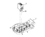
- the electric parts can be connected to the bus bar by a simple operation of inserting the two terminal portions into the connection ports of two relay terminals laid in advance. Connected.
- the current detection device according to the third invention is a form of the current detection device according to the second invention.
- the distance between both ends of the magnetic core is larger than the thickness of each of the two extension portions of the current detection bus bar.
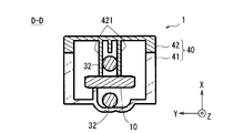
- the insulating housing includes a box member having an opening in the first direction and a lid member that is combined with the box member and closes the opening of the box member.
- the box member is formed with a bottom wall and a semi-cylindrical support portion shown below, and the lid member is formed with a rotation stop projection portion shown below. Yes.
- the current detection device according to the seventh invention is a form of the current detection device according to any one of the first invention to the sixth invention.
- the current detection bus bar is formed by pressing both ends of a bar-shaped metal member that can penetrate the hollow portion of the magnetic core into a flat plate having a width larger than that of the other portion. The crushed end portions constitute the two terminal portions.
- the direction in which the current detection bus bar passes through the hollow portion of the magnetic core (current passing direction) is the first direction.
- the direction in which the two terminal portions of the current detection bus bar protrude from the through portion through the two extension portions is a second direction orthogonal to the first direction.
- the direction orthogonal to both the first direction and the second direction is the third direction.
- the bar-shaped through portion is formed with a thickness larger than the terminal portions at both ends, so that the width and thickness of the through portion are smaller than the width of the hollow portion of the magnetic core.
- it can be formed with a larger cross-sectional area. Therefore, even when a relatively small magnetic core is employed, excessive heat generation of the current detection bus bar can be prevented.
- each component of the current detection device is held in a predetermined positional relationship by an insulating housing that covers other than the two terminal portions to be exposed. Therefore, according to the 2nd invention, the operation
- the insulating housing can prevent foreign matter from entering the gap between the magnetic core and the magnetoelectric conversion element, and can prevent current detection accuracy from deteriorating due to the foreign matter.
- a flat plate-like terminal portion having a width larger than the width of the hollow portion of the magnetic core can be easily formed at both ends of the rod-shaped metal member that is not plate-shaped.
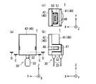
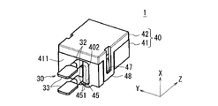
- the current detection device 1 is a device that detects a current flowing in a bus bar that electrically connects a battery and a device such as a motor in an electric vehicle or a hybrid vehicle. As illustrated in FIG. 1, the current detection device 1 includes a magnetic core 10, a Hall element 20, a folded bus bar 30, an insulating housing 40, and an electronic substrate 50.
- the magnetic core 10 has a shape in which both ends face each other via a gap portion 12 of about several millimeters and are formed in series around the periphery of the hollow portion 11.
- the magnetic core 10 has a narrow gap portion 12 but is formed in a generally annular shape.
- the magnetic core 10 in this embodiment is formed in an annular shape surrounding the circular hollow portion 11.
- the Hall element 20 is disposed in the gap portion 12 of the magnetic core 10, detects a magnetic flux that changes according to a current passing through the hollow portion 11 of the magnetic core 10, and outputs a magnetic flux detection signal as an electric signal. It is an example of a conversion element.
- the hall element 20 is formed with a connection terminal 21 for power input and detection signal output.
- the folded bus bar 30 is a member having a structure in which both end portions of a rod-shaped metal member capable of penetrating the hollow portion 11 of the magnetic core 10 are pressed into a flat plate shape having a width larger than other portions by pressing. is there. Both end portions crushed by the press working constitute two terminal portions 33 of the folded bus bar 30.
- the rod-shaped metal member that is the base of the folded bus bar 30 is formed in advance in a folded shape, for example.
- the folded bus bar 30 is produced by forming both end portions of such a metal member into a plate shape having a width larger than that of other portions by press working.
- the metal member that is the base of the folded busbar 30 is a straight bar.
- the straight bar-shaped metal member is formed into a plate shape having a width wider than that of the other portion by pressing at both ends, and then bent at two locations on both sides of the central portion.
- the folded bus bar 30 may be manufactured by such a procedure.
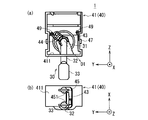
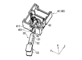
- the box member 41 is a box-shaped member having an opening formed in the first direction (the positive direction of the X axis). That is, the box member 41 is a member in which walls are formed in the remaining five directions excluding the first direction among the six directions of up and down, left and right, and front and rear.
- the lid member 42 is a member that closes the opening of the box member 41 by being combined with the box member 41.
- FIG. 7 is a perspective view of the box member 41 and the folded bus bar 30 before being inserted into the box member 41 in the current detection device 1.
- the folded bus bar 30 extends from the bus bar hole 45 of the bottom wall 411 to the inside of the box member 41 along the direction between the second direction and the third direction with the penetrating portion 31 as the head. Inserted.
- FIG. 10 is a perspective view of the box member 41 in the current detection device 1, the folded bus bar 30 supported by the box member 41, and the magnetic core 10 through which the extension 32 of the folded bus bar 30 passes.
- the magnetic core 10 before being hooked on the folded bus bar 30 is drawn with a virtual line (two-dot chain line).
- the dimension of the current detection device 1 in the first direction is small enough to add the diameters of the two extended portions 32 of the folded bus bar 30 to the thickness of the magnetic core 10. That's it. Further, the dimension of the current detection device 1 in the third direction (Y-axis direction) may be as small as the width of the magnetic core 10.
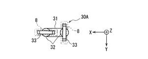
- the two terminal portions 33 are formed in a flat plate shape along each of two parallel planes or two orthogonal planes, and each of two planes intersecting at an angle other than 90 °. It may be formed in a flat plate shape.
Landscapes
- Physics & Mathematics (AREA)
- General Physics & Mathematics (AREA)
- Condensed Matter Physics & Semiconductors (AREA)
- Measuring Instrument Details And Bridges, And Automatic Balancing Devices (AREA)
Abstract
Description
(1)第1の構成要素は、磁性材料からなり、両端がギャップ部を介して対向し、中空部の周囲を囲んで一連に形成された磁性体コアである。
(2)第2の構成要素は、磁性体コアのギャップ部に配置され、磁性体コアの中空部を通過する電流に応じて変化する磁束を検出する磁電変換素子である。
(3)第3の構成要素は、磁性体コアの中空部を貫通する導体からなる電流検出用バスバーである。この電流検出用バスバー電流検出用バスバーは、全体が折り返した形状で形成され、以下に示される貫通部と2つの延長部と2つの端子部とを有する。貫通部は、磁性体コアの中空部を第1方向に沿って貫通する棒状の部分である。2つの延長部は、貫通部に対し第1方向の前後両側各々に連なり第1方向に直交する第2方向へ平行に延びる棒状の部分である。2つの端子部は、2つの延長部各々に対し第2方向側に連なり貫通部及び延長部よりも幅が大きい平板状に形成された部分である。
(4)第4の構成要素は、絶縁材料からなり、2つの端子部が外部に露出する状態で、磁性体コアと磁電変換素子と電流検出用バスバーにおける2つの延長部各々の一部及び貫通部とを覆いつつ、磁性体コアと磁電変換素子と電流検出用バスバーとを一定の位置関係で支持する絶縁筐体である。
磁性体コア10は、パーマロイ、フェライト又はケイ素鋼などの磁性材料からなる部材(磁性体)である。磁性体コア10は、例えば、磁性材料からなる粉体の焼結により成形された部材である。そのような磁性体コア10は、磁性材料からなる固体粉末の集合体が、型枠内で圧縮され、さらに、その磁性体材料の融点よりも低い温度で加熱されることによって固化及び成形された部材である。或いは、磁性体コア10は、積層タイプの磁性体コアであってもよい。
ホール素子20は、磁性体コア10のギャップ部12に配置され、磁性体コア10の中空部11を通過する電流に応じて変化する磁束を検出し、磁束の検出信号を電気信号として出力する磁電変換素子の一例である。このホール素子20には、電力の入力用及び検出信号の出力用の接続端子21が延び出て形成されている。
電子基板50は、ホール素子20の接続端子21と電気的に接続される回路と、その回路と外部の他の回路とを接続するためのコネクタ51とが実装された基板である。従って、コネクタ51は、ホール素子20に対して電気的に接続されている。電子基板50に実装された回路は、例えば、ホール素子20に供給される電流を調整する回路、及びホール素子20から出力される磁束の検出信号を増幅する回路などを含む。ホール素子20は、コネクタ51を含む電子基板50を介して、制御部などの外部の回路と接続される。
折返しバスバー30は、軟銅又はアルミニウムなどの金属からなる導電体であり、バッテリ又はインバータ回路などの一次側の機器とモータなどの二次側の機器とを電気的に接続するバスバーの一部である。即ち、折返しバスバー30は、検出対象の電流が流れる電流検出用のバスバーである。また、折返しバスバー30は、一次側の機器に対して予め接続された前段バスバーと、二次側の機器に対して予め接続された後段バスバーとは独立した部材である。
絶縁筐体40は、絶縁材料からなり、磁性体コア10とホール素子20と折返しバスバー30と電子基板50とを一定の位置関係で支持する部材である。絶縁筐体40は、箱部材41及び箱部材41と組み合わされる蓋部材42からなる。箱部材41及び蓋部材42の各々は、例えば、ポリアミド(PA)、ポリプロピレン(PP)、ポリブチレンテレフタレート(PBT)又はABS樹脂などの絶縁性の樹脂からなる一体成形部材である。
以下、図7から図12を参照しつつ、電流検出装置1の組み立て手順の一例について説明する。
以上に示した電流検出装置1において、折返しバスバー30の両端部は端子部33である。即ち、予め敷設された前段及び後段のバスバー9に対し、磁性体コア10の中空部11を貫通した状態の折返しバスバー30を後から連結することが可能である。そのため、前段及び後段のバスバー9とは異なる異形の折返しバスバー30を採用することが可能であり、前段及び後段のバスバー9の幅の制約を受けずに小型の磁性体コア10を採用することができる。
電流検出装置1において、折返しバスバー30の貫通部31が角柱状であり、第1支持部43の内側面が、貫通部31の外形に沿う多角形状であってもよい。例えば、筒状の第1支持部43の開放部が、第3方向(Y軸方向)に向いていることが考えられる。この場合、折返しバスバー30の貫通部31が、四角柱状、六角柱状又は八角柱状などの多角柱状であっても、2つの端子部33が第2方向(Z軸の負方向)に向く状態で、貫通部31を第3方向に沿って第1支持部43の内側に嵌め入れることができる。
8 中継端子
9 他のバスバー
10 磁性体コア
11 磁性体コアの中空部
12 磁性体コアのギャップ部
20 ホール素子
21 ホール素子の接続端子
30,30A 折返しバスバー
31 折返しバスバーの貫通部
32 折返しバスバーの延長部
33 折返しバスバーの端子部
40 絶縁筐体
41 箱部材
42 蓋部材
43 第1支持部
44 第2支持部
45 バスバー孔
46 欠け部
47 爪部(ロック機構)
48 枠部(ロック機構)
49 基板支持部
50 電子基板
51 コネクタ
411 底壁
421 回転止め突起部
422 遮蔽板
451 切れ込み部
501 欠け部
502 実装用の孔
Claims (7)
- 磁性材料からなり、両端がギャップ部(12)を介して対向し、中空部(11)の周囲を囲んで一連に形成された磁性体コア(10)と、
前記磁性体コア(10)の前記ギャップ部(12)に配置され、前記磁性体コア(10)の前記中空部(11)を通過する電流に応じて変化する磁束を検出する磁電変換素子(20)と、
前記磁性体コア(10)の前記中空部(11)を貫通する導体からなる電流検出用バスバー(30)と、を備える電流検出装置(1)であって、
前記電流検出用バスバー(30)は、
全体が折り返した形状で形成され、
前記磁性体コア(10)の前記中空部(11)を第1方向に沿って貫通する棒状の貫通部(31)と、
前記貫通部(31)に対し前記第1方向の前後両側各々に連なり前記第1方向に直交する第2方向へ平行に延びる棒状の2つの延長部(32)と、
2つの前記延長部(32)各々に対し前記第2方向側に連なり前記貫通部(31)及び前記延長部(32)よりも幅が大きい平板状に形成された2つの端子部(33)と、を有することを特徴とする電流検出装置(1)。 - 絶縁材料からなり、2つの前記端子部(33)が外部に露出する状態で、前記磁性体コア(10)と前記磁電変換素子(20)と前記電流検出用バスバー(30)における2つの前記延長部(32)各々の一部及び前記貫通部(31)とを覆いつつ、前記磁性体コア(10)と前記磁電変換素子(20)と前記電流検出用バスバー(30)とを一定の位置関係で支持する絶縁筐体(40)をさらに備える、請求項1に記載の電流検出装置(1)。
- 前記磁性体コア(10)の両端の間隔は、前記電流検出用バスバー(30)の2つの前記延長部(32)各々の厚みよりも大きく、
前記絶縁筐体(40)は、前記第1方向に開口が形成された箱部材(41)及び該箱部材(42)と組み合わされて前記箱部材の前記開口を塞ぐ蓋部材(42)からなり、
前記箱部材(41)には、
前記電流検出用バスバー(30)を挿入可能な貫通孔(45)が形成され前記第2方向の端の壁を形成する底壁(411)と、
前記第1方向を軸心方向とし前記第2方向に対して交差する方向に向く側面の開放部が形成された半筒状に形成され、前記磁性体コア(10)の前記中空部(11)における前記磁性体コア(11)の内縁と前記電流検出用バスバー(30)の前記貫通部(31)との間に挿入された状態で、外側面で前記磁性体コア(10)を支持するとともに内側面で前記電流検出用バスバー(30)を支持する半筒状支持部(43)と、が形成され、
前記蓋部材(42)には、
前記第1方向に沿って突出して形成され、前記半筒支持部(43)に支持された前記電流検出用バスバー(30)の前記延長部(32)に接して前記電流検出用バスバー(30)の回動を制限する回動止め突起部(421)が形成されている、請求項2に記載の電流検出装置(1)。 - 前記電流検出用バスバー(30)の前記貫通部(31)は円柱状であり、
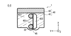
前記箱部材(41)の前記半筒状支持部(43)は半円筒状である、請求項3に記載の電流検出装置(1)。 - 前記箱部材(41)の前記底壁(411)における前記貫通孔(45)の縁には、前記第1方向及び前記第2方向に直交する第3方向へ凹み、前記電流検出用バスバー(30)における2つの前記延長部(32)各々が嵌り込む2つの切れ込み部(451)が形成され、
前記蓋部材(42)には、前記第1方向に沿って突出して形成され、前記箱部材(41)の前記底壁(411)における前記貫通孔(45)のうち前記切れ込み部(451)に嵌り込んだ2つの前記延長部(32)が占める領域以外の領域を塞ぐ遮蔽板(422)が形成されている、請求項3又は請求項4に記載の電流検出装置(1)。 - 2つの前記端子部(33)各々は、直交する2平面各々に沿う平板状に形成されている、請求項1から請求項5のいずれかに記載の電流検出装置(1)。
- 前記電流検出用バスバー(30)は、前記磁性体コア(10)の前記中空部(11)を貫通可能な棒状の金属部材の両端部分がプレス加工により他の部分よりも大きい幅の平板状に押しつぶされて成形された構造を有する部材であり、押しつぶされた両端部分が2つの前記端子部(33)を構成する、請求項1から請求項6のいずれかに記載の電流検出装置(1)。
Priority Applications (3)
| Application Number | Priority Date | Filing Date | Title |
|---|---|---|---|
| CN201180071459.5A CN103597362B (zh) | 2011-06-15 | 2011-10-24 | 电流检测装置 |
| US14/117,802 US9255976B2 (en) | 2011-06-15 | 2011-10-24 | Current detection device |
| DE112011105156.5T DE112011105156T5 (de) | 2011-06-15 | 2011-10-24 | Stromerfassungseinrichtung |
Applications Claiming Priority (2)
| Application Number | Priority Date | Filing Date | Title |
|---|---|---|---|
| JP2011132953A JP5724660B2 (ja) | 2011-06-15 | 2011-06-15 | 電流検出装置 |
| JP2011-132953 | 2011-06-15 |
Publications (1)
| Publication Number | Publication Date |
|---|---|
| WO2012172701A1 true WO2012172701A1 (ja) | 2012-12-20 |
Family
ID=47356726
Family Applications (1)
| Application Number | Title | Priority Date | Filing Date |
|---|---|---|---|
| PCT/JP2011/074380 Ceased WO2012172701A1 (ja) | 2011-06-15 | 2011-10-24 | 電流検出装置 |
Country Status (5)
| Country | Link |
|---|---|
| US (1) | US9255976B2 (ja) |
| JP (1) | JP5724660B2 (ja) |
| CN (1) | CN103597362B (ja) |
| DE (1) | DE112011105156T5 (ja) |
| WO (1) | WO2012172701A1 (ja) |
Cited By (1)
| Publication number | Priority date | Publication date | Assignee | Title |
|---|---|---|---|---|
| US20220178972A1 (en) * | 2019-03-15 | 2022-06-09 | Tdk Corporation | Current sensor |
Families Citing this family (11)
| Publication number | Priority date | Publication date | Assignee | Title |
|---|---|---|---|---|
| EP3093672B1 (en) * | 2015-05-09 | 2020-08-12 | LEM International SA | Current transducer with integrated primary conductor bar |
| EP3159705A1 (en) * | 2015-10-23 | 2017-04-26 | LEM Intellectual Property SA | Current transducer with integrated primary conductor |
| US10421367B2 (en) * | 2015-10-30 | 2019-09-24 | Faraday & Future Inc. | Electric vehicle battery test |
| JP6183440B2 (ja) * | 2015-11-20 | 2017-08-23 | 株式会社安川電機 | 電力変換装置及びノイズフィルタ |
| WO2017192256A1 (en) * | 2016-05-04 | 2017-11-09 | Safran Electrical & Power | Busbar current sensor assembly |
| WO2018012032A1 (ja) * | 2016-07-15 | 2018-01-18 | アルプス電気株式会社 | 電流センサ |
| FR3082368B1 (fr) * | 2018-06-08 | 2022-02-04 | Schneider Electric Ind Sas | Boitier de protection pour une installation electrique et installation electrique comportant un tel boitier de protection |
| JP2020085544A (ja) * | 2018-11-19 | 2020-06-04 | アイシン精機株式会社 | 電流センサ |
| JP1634630S (ja) * | 2018-11-28 | 2019-06-24 | ||
| DE112023001219T5 (de) * | 2022-03-03 | 2025-01-16 | Asahi Kasei Microdevices Corporation | Stromsensor und Stromerkennungsverfahren |
| CN115602438B (zh) * | 2022-11-10 | 2023-06-20 | 清远市震东电子科技有限公司 | 一种用于磁耦合电感器的磁芯制备工艺 |
Citations (3)
| Publication number | Priority date | Publication date | Assignee | Title |
|---|---|---|---|---|
| JPH06130087A (ja) * | 1992-10-21 | 1994-05-13 | Tokin Corp | 電流検出器 |
| JPH0993771A (ja) * | 1995-09-20 | 1997-04-04 | Yazaki Corp | 電気接続箱のバスバー構造 |
| JP2003045231A (ja) * | 2001-07-30 | 2003-02-14 | Yaskawa Electric Corp | 制御器用ブスバー |
Family Cites Families (9)
| Publication number | Priority date | Publication date | Assignee | Title |
|---|---|---|---|---|
| JP3211939B2 (ja) | 1996-09-30 | 2001-09-25 | 矢崎総業株式会社 | 電気接続箱 |
| WO2003056347A1 (en) * | 2001-12-27 | 2003-07-10 | Matsushita Electric Industrial Co., Ltd. | Current sensor |
| JP2006166528A (ja) | 2004-12-03 | 2006-06-22 | Yazaki Corp | 電気接続箱 |
| JP2007028773A (ja) * | 2005-07-14 | 2007-02-01 | Sumitomo Wiring Syst Ltd | 車載用電気接続箱 |
| JP2009058451A (ja) | 2007-09-03 | 2009-03-19 | Osaki Electric Co Ltd | 電流センサ用磁気コアおよびこれを用いた電流センサ |
| JP5030226B2 (ja) * | 2007-10-17 | 2012-09-19 | 矢崎総業株式会社 | 電気接続箱 |
| JP4424412B2 (ja) | 2007-11-21 | 2010-03-03 | 株式会社デンソー | 電流センサ |
| DE102008051561B4 (de) * | 2008-10-14 | 2013-06-20 | Vacuumschmelze Gmbh & Co. Kg | Verfahren zum Herstellen einer Stromerfassungseinrichtung |
| JP4575992B1 (ja) * | 2010-01-20 | 2010-11-04 | 文雄 渡辺 | 回転駆動装置 |
-
2011
- 2011-06-15 JP JP2011132953A patent/JP5724660B2/ja not_active Expired - Fee Related
- 2011-10-24 US US14/117,802 patent/US9255976B2/en not_active Expired - Fee Related
- 2011-10-24 DE DE112011105156.5T patent/DE112011105156T5/de not_active Withdrawn
- 2011-10-24 WO PCT/JP2011/074380 patent/WO2012172701A1/ja not_active Ceased
- 2011-10-24 CN CN201180071459.5A patent/CN103597362B/zh not_active Expired - Fee Related
Patent Citations (3)
| Publication number | Priority date | Publication date | Assignee | Title |
|---|---|---|---|---|
| JPH06130087A (ja) * | 1992-10-21 | 1994-05-13 | Tokin Corp | 電流検出器 |
| JPH0993771A (ja) * | 1995-09-20 | 1997-04-04 | Yazaki Corp | 電気接続箱のバスバー構造 |
| JP2003045231A (ja) * | 2001-07-30 | 2003-02-14 | Yaskawa Electric Corp | 制御器用ブスバー |
Cited By (1)
| Publication number | Priority date | Publication date | Assignee | Title |
|---|---|---|---|---|
| US20220178972A1 (en) * | 2019-03-15 | 2022-06-09 | Tdk Corporation | Current sensor |
Also Published As
| Publication number | Publication date |
|---|---|
| US20140084914A1 (en) | 2014-03-27 |
| JP2013002894A (ja) | 2013-01-07 |
| DE112011105156T5 (de) | 2014-01-16 |
| US9255976B2 (en) | 2016-02-09 |
| CN103597362A (zh) | 2014-02-19 |
| JP5724660B2 (ja) | 2015-05-27 |
| CN103597362B (zh) | 2016-01-06 |
Similar Documents
| Publication | Publication Date | Title |
|---|---|---|
| JP5724660B2 (ja) | 電流検出装置 | |
| JP5464098B2 (ja) | 電流検出装置 | |
| JP5817508B2 (ja) | 電流検出装置 | |
| US9086440B2 (en) | Current sensor | |
| JP5533441B2 (ja) | 電流検出装置及びその製造方法 | |
| US8952688B2 (en) | Current Detector | |
| WO2013005450A1 (ja) | 電流検出装置 | |
| US9170283B2 (en) | Current detector | |
| JP2013120177A (ja) | 電流検出装置 | |
| JP2017044486A (ja) | 電流センサ | |
| JP2013101795A (ja) | 電流検出装置のバスバー接続構造 | |
| JP2012042409A (ja) | 電流検出装置 | |
| JP2012047564A (ja) | 電流検出装置 | |
| JP2012247197A (ja) | 電流検出装置及び磁性体コア | |
| JP2013044671A (ja) | 電流検出装置 | |
| JP2013217866A (ja) | 電気接続箱及び電流センサ | |
| JP2012255725A (ja) | 電流検出装置 | |
| JP5532843B2 (ja) | 電流検出装置 | |
| JP2013002901A (ja) | 電流検出装置 | |
| JP2013148499A (ja) | 電流検出装置 | |
| WO2012026256A1 (ja) | 電流検出装置 | |
| JP2013024571A (ja) | バスバー | |
| JP2013019795A (ja) | 電流検出装置 | |
| JP2013200140A (ja) | 電流検出装置 | |
| JP2020088345A (ja) | リアクトル |
Legal Events
| Date | Code | Title | Description |
|---|---|---|---|
| 121 | Ep: the epo has been informed by wipo that ep was designated in this application |
Ref document number: 11867622 Country of ref document: EP Kind code of ref document: A1 |
|
| WWE | Wipo information: entry into national phase |
Ref document number: 112011105156 Country of ref document: DE Ref document number: 1120111051565 Country of ref document: DE |
|
| WWE | Wipo information: entry into national phase |
Ref document number: 14117802 Country of ref document: US |
|
| 122 | Ep: pct application non-entry in european phase |
Ref document number: 11867622 Country of ref document: EP Kind code of ref document: A1 |