WO2012169553A1 - 光学表示装置の製造システムおよび光学表示装置の製造方法 - Google Patents
光学表示装置の製造システムおよび光学表示装置の製造方法 Download PDFInfo
- Publication number
- WO2012169553A1 WO2012169553A1 PCT/JP2012/064599 JP2012064599W WO2012169553A1 WO 2012169553 A1 WO2012169553 A1 WO 2012169553A1 JP 2012064599 W JP2012064599 W JP 2012064599W WO 2012169553 A1 WO2012169553 A1 WO 2012169553A1
- Authority
- WO
- WIPO (PCT)
- Prior art keywords
- unwinding
- polarizing film
- film
- bonding
- polarizing
- Prior art date
- Legal status (The legal status is an assumption and is not a legal conclusion. Google has not performed a legal analysis and makes no representation as to the accuracy of the status listed.)
- Ceased
Links
Images


Classifications
-
- B—PERFORMING OPERATIONS; TRANSPORTING
- B32—LAYERED PRODUCTS
- B32B—LAYERED PRODUCTS, i.e. PRODUCTS BUILT-UP OF STRATA OF FLAT OR NON-FLAT, e.g. CELLULAR OR HONEYCOMB, FORM
- B32B38/00—Ancillary operations in connection with laminating processes
- B32B38/18—Handling of layers or the laminate
-
- G—PHYSICS
- G02—OPTICS
- G02F—OPTICAL DEVICES OR ARRANGEMENTS FOR THE CONTROL OF LIGHT BY MODIFICATION OF THE OPTICAL PROPERTIES OF THE MEDIA OF THE ELEMENTS INVOLVED THEREIN; NON-LINEAR OPTICS; FREQUENCY-CHANGING OF LIGHT; OPTICAL LOGIC ELEMENTS; OPTICAL ANALOGUE/DIGITAL CONVERTERS
- G02F1/00—Devices or arrangements for the control of the intensity, colour, phase, polarisation or direction of light arriving from an independent light source, e.g. switching, gating or modulating; Non-linear optics
- G02F1/01—Devices or arrangements for the control of the intensity, colour, phase, polarisation or direction of light arriving from an independent light source, e.g. switching, gating or modulating; Non-linear optics for the control of the intensity, phase, polarisation or colour
- G02F1/13—Devices or arrangements for the control of the intensity, colour, phase, polarisation or direction of light arriving from an independent light source, e.g. switching, gating or modulating; Non-linear optics for the control of the intensity, phase, polarisation or colour based on liquid crystals, e.g. single liquid crystal display cells
- G02F1/1303—Apparatus specially adapted to the manufacture of LCDs
-
- B—PERFORMING OPERATIONS; TRANSPORTING
- B32—LAYERED PRODUCTS
- B32B—LAYERED PRODUCTS, i.e. PRODUCTS BUILT-UP OF STRATA OF FLAT OR NON-FLAT, e.g. CELLULAR OR HONEYCOMB, FORM
- B32B2457/00—Electrical equipment
- B32B2457/20—Displays, e.g. liquid crystal displays, plasma displays
- B32B2457/202—LCD, i.e. liquid crystal displays
-
- B—PERFORMING OPERATIONS; TRANSPORTING
- B32—LAYERED PRODUCTS
- B32B—LAYERED PRODUCTS, i.e. PRODUCTS BUILT-UP OF STRATA OF FLAT OR NON-FLAT, e.g. CELLULAR OR HONEYCOMB, FORM
- B32B37/00—Methods or apparatus for laminating, e.g. by curing or by ultrasonic bonding
- B32B37/14—Methods or apparatus for laminating, e.g. by curing or by ultrasonic bonding characterised by the properties of the layers
- B32B37/16—Methods or apparatus for laminating, e.g. by curing or by ultrasonic bonding characterised by the properties of the layers with all layers existing as coherent layers before laminating
- B32B37/18—Methods or apparatus for laminating, e.g. by curing or by ultrasonic bonding characterised by the properties of the layers with all layers existing as coherent layers before laminating involving the assembly of discrete sheets or panels only
- B32B37/182—Methods or apparatus for laminating, e.g. by curing or by ultrasonic bonding characterised by the properties of the layers with all layers existing as coherent layers before laminating involving the assembly of discrete sheets or panels only one or more of the layers being plastic
- B32B37/185—Laminating sheets, panels or inserts between two discrete plastic layers
-
- G—PHYSICS
- G02—OPTICS
- G02B—OPTICAL ELEMENTS, SYSTEMS OR APPARATUS
- G02B5/00—Optical elements other than lenses
- G02B5/30—Polarising elements
- G02B5/3025—Polarisers, i.e. arrangements capable of producing a definite output polarisation state from an unpolarised input state
- G02B5/3033—Polarisers, i.e. arrangements capable of producing a definite output polarisation state from an unpolarised input state in the form of a thin sheet or foil, e.g. Polaroid
-
- G—PHYSICS
- G02—OPTICS
- G02F—OPTICAL DEVICES OR ARRANGEMENTS FOR THE CONTROL OF LIGHT BY MODIFICATION OF THE OPTICAL PROPERTIES OF THE MEDIA OF THE ELEMENTS INVOLVED THEREIN; NON-LINEAR OPTICS; FREQUENCY-CHANGING OF LIGHT; OPTICAL LOGIC ELEMENTS; OPTICAL ANALOGUE/DIGITAL CONVERTERS
- G02F1/00—Devices or arrangements for the control of the intensity, colour, phase, polarisation or direction of light arriving from an independent light source, e.g. switching, gating or modulating; Non-linear optics
- G02F1/01—Devices or arrangements for the control of the intensity, colour, phase, polarisation or direction of light arriving from an independent light source, e.g. switching, gating or modulating; Non-linear optics for the control of the intensity, phase, polarisation or colour
- G02F1/13—Devices or arrangements for the control of the intensity, colour, phase, polarisation or direction of light arriving from an independent light source, e.g. switching, gating or modulating; Non-linear optics for the control of the intensity, phase, polarisation or colour based on liquid crystals, e.g. single liquid crystal display cells
- G02F1/133—Constructional arrangements; Operation of liquid crystal cells; Circuit arrangements
- G02F1/1333—Constructional arrangements; Manufacturing methods
- G02F1/1335—Structural association of cells with optical devices, e.g. polarisers or reflectors
- G02F1/133528—Polarisers
Definitions
- the present invention relates to an optical display device manufacturing system and an optical display device manufacturing method.
- Patent Literature 1 and Patent Literature 2 disclose an apparatus for laminating an optical film.
- sticking can be performed by controlling the width direction of the belt-like film or film piece and the width direction of the substrate to correspond to each other.
- the optical member bonding apparatus of patent document 2 it is possible to cut
- Patent Document 3 discloses a laminating machine that joins a plurality of raw rolls with a turret.
- Japanese Patent Publication Japanese Unexamined Patent Application Publication No. 2004-361741 (Released on December 24, 2004)” Japanese Patent Publication “JP 2009-61498 A (published March 26, 2009)” Japanese Patent Publication “JP-A-8-208083 (published on August 13, 1996)”
- the above-described conventional manufacturing system has a problem that the production efficiency of the optical display panel is insufficient or the apparatus is enlarged.
- an unwinding portion in which an original fabric roll of a polarizing film is installed is provided at one location.
- the operator cuts the polarizing film of the used original roll and removes it from the unwinding section, and then puts the new original roll into the unwinding section. Install and bond the polarizing film of the new original roll and the polarizing film remaining in the line.
- Such replacement work takes a long time, and during that time, it is necessary to stop the operation of the manufacturing system, which is one factor in reducing the production efficiency of the optical display panel.
- the present invention has been made in view of the above-described conventional problems, and an object of the present invention is to provide a manufacturing system for a miniaturized optical display device that can shorten the manufacturing time of the optical display device. is there.
- the inventors of the present invention have studied the target manufacturing system, and found that it is desirable to bond from the lower surface of the liquid crystal panel when the polarizing film is bonded to the liquid crystal panel.
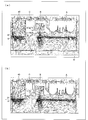
- FIGS. 15A and 15B are diagrams showing the vector direction of airflow (down flow) when a polarizing film is bonded to the upper surface of the liquid crystal panel.
- region A is a region where an unwinding part and the like for unwinding the polarizing film are installed
- region B is a region through which the polarizing film mainly passes
- region C is This is an area in which a winding unit and the like for winding the protective film removed from the polarizing film are installed.
- clean air is supplied from an HEPA (High Efficiency Particulate Air) filter 40.
- HEPA High Efficiency Particulate Air
- regions A to C are arranged on the 2F (second floor) portion, and a transport mechanism for transporting the liquid crystal panel is installed between 1F and 2F. Since the clean air from the HEPA filter 40 is blocked by the areas A to C, it is difficult to generate an airflow in the vertical direction with respect to the liquid crystal panel passing through the 2F portion. On the other hand, the airflow vector in the horizontal direction is large (vector density is high). That is, it was found that the air flow toward the upper side of the liquid crystal panel transported by the transport mechanism is less likely to occur, and the rectification environment has deteriorated.
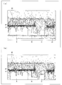
- FIGS. 16 (a) and 16 (b) the vector direction of the airflow (down flow) when a polarizing film is bonded to the lower surface of the liquid crystal panel is shown in FIGS. 16 (a) and 16 (b).
- the clean air supplied from the HEPA filter 40 goes to the transport mechanism between 1F and 2F without being blocked by the areas A to C, and the rectifying environment is not blocked.
- FIG. 16A since the grating 41 through which clean air can pass is installed, the airflow can move in the vertical direction via the grating 41.
- the bonding mechanism is a protective film.
- the peeling part which peels a protective film from a film, the bonding part which bonds the polarizing film from which the protective film was peeled to the lower surface of a liquid crystal panel, and the winding part which winds up the protective film peeled from the said polarizing film
- the transport mechanism includes a reversing unit for reversing the liquid crystal panel having the polarizing film bonded to the lower surface by one bonding mechanism, and the first unwinding unit and the second unwinding unit. Are movable horizontally along the core direction of the polarizing film, the first unwinding unit and the second unwinding unit, are juxtaposed to each other.
- a polarizing film is bonded to the lower surface of the liquid crystal panel by one bonding mechanism with respect to the liquid crystal panel conveyed by the conveyance mechanism.
- This liquid crystal panel was inverted by the reversing part, and the polarizing film was bonded to the lower surface of the liquid crystal panel by the other bonding mechanism, and the liquid crystal panel was bonded to both surfaces of the liquid crystal film without deteriorating the rectifying environment in the manufacturing system.
- An optical display device is manufactured.
- the bonding mechanism of the manufacturing system is provided with two unwinding portions, a first unwinding portion and a second unwinding portion, which are provided side by side. For this reason, when the remaining amount of the polarizing film in the first unwinding portion is almost exhausted, the polarizing film in the second unwinding portion is used without replacing the polarizing film roll in the first unwinding portion with a new roll.
- the polarizing films of both unwinding portions can be immediately connected to each other, and the polarizing film can be unwound quickly. Therefore, since the time required for the replacement work of the original fabric roll can be reduced, the manufacturing time of the optical display device can be shortened.
- both unwinding parts can move horizontally along the winding core direction of the polarizing film, when replacing the polarizing film, a new original roll of polarizing film is added to the unwinding part moved in the horizontal direction. Can be installed. Therefore, unlike a laminating machine having a conventional turret, the unwinding portion does not move upward. For this reason, the range which an unwinding part moves can be made small, and the manufacturing system reduced in size can be provided.
- the optical display device manufacturing system of the present invention includes the transport mechanism for transporting the liquid crystal panel and the two bonding mechanisms for bonding the polarizing film to the lower surface of the liquid crystal panel.
- the bonding mechanism of the above manufacturing system is provided with two unwinding portions, a first unwinding portion and a second unwinding portion, which are provided side by side. For this reason, when the remaining amount of the polarizing film in the first unwinding portion is almost exhausted, the polarizing film in the second unwinding portion is used without replacing the polarizing film roll in the first unwinding portion with a new roll.
- the polarizing films of both unwinding portions can be immediately connected to each other, and the polarizing film can be unwound quickly. Therefore, since the time required for the replacement work of the original fabric roll can be reduced, the manufacturing time of the optical display device can be shortened.
- both the unwinding portions can be moved horizontally along the winding core direction of the polarizing film, when replacing the polarizing film, a new polarizing film original is added to the unwinding portion moved in the horizontal direction. Anti-roll can be installed. Therefore, unlike a laminating machine having a conventional turret, the unwinding portion does not move upward. For this reason, it is possible to reduce the range in which the unwinding part moves and to provide an effect that a miniaturized manufacturing system can be provided.
- A) is a perspective view which shows the state before the unwinding part which concerns on this invention moves
- (b) is a perspective view which shows the state after the unwinding part which concerns on this invention moved.
- (A)-(h) is process drawing which shows the connection process by the manufacturing system based on this invention.
- FIGS. 1 to 14 An embodiment of the present invention will be described with reference to FIGS. 1 to 14 as follows.
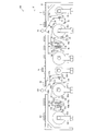
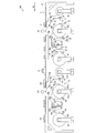
- FIG. 1 is a side view showing an optical display device manufacturing system 100 according to the present invention.
- the manufacturing system 100 unwinds the laminated film 10, peels the protective film 10 a from the laminated film 10, and bonds the polarizing film 10 b to one side of the liquid crystal panel 2. Thereafter, the manufacturing system 100 bonds the polarizing film 110b to the opposite surface of the liquid crystal panel 2, and the optical display device is manufactured.
- the liquid crystal panel 2 a known liquid crystal panel may be used, and a known liquid crystal panel in which an alignment film is disposed between a substrate such as a glass substrate and a liquid crystal layer may be used.
- the manufacturing system 100 is roughly classified and includes a transport mechanism 12 and two bonding mechanisms. As each member of the 1st pasting mechanism, unwinding part (1st unwinding part) 1, unwinding part (2nd unwinding part) 1a, film connection part (1st film connection part) 3, film connection Part (second film connecting part) 13, guide roller 16, half cutter 21, support base 22, knife edge (peeling part) 23, nip rollers 24 and 24 a, and take-up part 25 (100 of the manufacturing system). Right).
- “•” means “and”.
- the manufacturing system 100 includes an unwinding part (first unwinding part) 101, an unwinding part (second unwinding part) 101a, a film connecting part (first film connecting part) 103, and a film connecting part (second film connecting part). Part) 113, a guide roller 116, a half cutter 121, a support stand 122, a knife edge 123, nip rollers 124 and 124a, and a winding part 125.
- the first bonding mechanism and the second bonding mechanism are installed below the transport mechanism 12.
- the first bonding mechanism is such that the nip rollers 24 and 24a are positioned upstream of the transport path of the liquid crystal panel 2
- the second bonding mechanism is such that the nip rollers 124 and 124a are positioned downstream of the transport path of the liquid crystal panel 2. Has been placed.
- the nip rollers 24 and 124 are provided near the upper surface of the liquid crystal panel 2, and the nip rollers 24a and 124a are provided at a possible height on the lower surface of the liquid crystal panel.
- each member other than the nip rollers in both the bonding mechanisms is provided below the transport mechanism 12. Further, the transport mechanism 12 includes a reversing unit 26. Hereinafter, each member will be described.
- the unwinding part 1 and the unwinding part 1a are apparatuses for holding and unwinding the raw roll of the laminated films 10 and 20 in which the protective films 10a and 20a protect the polarizing films 10b and 20b through the adhesive layer.
- the tension applied to the laminated films 10 and 20 can be adjusted.
- the laminated film 10 unwound from the unwinding unit 1 is sent to the line side via each guide roller 16.
- the line refers to the path through which the laminated film 10 is conveyed
- the line direction refers to the direction in which the laminated film 10 is conveyed.
- the unwinding part side means the direction opposite to the line side. The same applies to the line of the laminated film 20 that is unwound from the unwinding portion 1a.
- a raw roll R1a is installed in the unwinding portion 1a, and this raw roll R1a is used for replenishment. When the remaining amount of the raw roll R1 in the unwinding unit 1 is almost exhausted, the raw roll R1a is unwound and the laminated films 10 and 20 are connected. Details of the unwinding portions 1 and 1a will be described later with reference to FIG.
- the laminated film 10 is a film in which a protective film 10a is laminated on a polarizing film 10b bonded to the liquid crystal panel 2 via an adhesive layer, and is sent out via a guide roller 16. It can be said that the laminated film 10 is a polarizing film whose surface is protected by a protective film.
- tensile_strength, etc. which unwind the laminated
- What is necessary is just to change suitably the width
- an unwinding portion having a width capable of installing the laminated film 10 having a film width of 300 mm or more and 1200 mm or less may be used.
- the laminated film 10 has a three-layer structure, and can adopt a known structure, and includes a protective film 10a, an adhesive layer (not shown), and a polarizing film 10b.
- a TAC (triacetylcellulose) film or the like is bonded as a protective film on both sides of the polarizer film, and an adhesive layer is applied (laminated) to one or both TAC films.
- stacked on the adhesion layer is mentioned.
- polarizer film a polyvinyl alcohol film dyed with iodine or the like and a film stretched in a uniaxial direction can be used. Also, in place of the above films, partially formalized polyvinyl alcohol film, ethylene / vinyl acetate copolymer partially saponified film, hydrophilic polymer film such as cellulose film, etc., dehydrated polyvinyl alcohol and polyvinyl chloride A polyene-oriented film such as a dehydrochlorinated product can also be used.
- the width of the polarizing film 10b can be 300 mm or more and 1200 mm or less.
- the polarizing film 10b is bonded with the short side of the liquid crystal panel 2 along the transport direction D1 of the liquid crystal panel 2, and then the length of the liquid crystal panel 2 in the transport direction D1 of the liquid crystal panel 2.
- the polarizing film 10b is bonded in a state where the sides are aligned. Therefore, the width of the polarizing film 10 b is a length corresponding to the long side of the liquid crystal panel 2, and the width of the polarizing film 110 b is a length corresponding to the short side of the liquid crystal panel 2.
- the total thickness of the protective film 10a, the pressure-sensitive adhesive layer, and the polarizing film 10b is not particularly limited, but can be 100 ⁇ m or more and 500 ⁇ m or less as an example.
- the thickness of a polarizer film is 10 micrometers or more and 50 micrometers or less among polarizing films 10b * 110b.
- other layers may be included within the practical range of the laminated film 10.
- the adhesive layer is used to bond the polarizing film 10b and the liquid crystal panel 2 after the protective film 10a is removed.
- the pressure-sensitive adhesive used for the pressure-sensitive adhesive layer is not particularly limited, and an acrylic, epoxy, polyurethane-based pressure-sensitive adhesive can be used, but it needs to be easily peeled off from the protective film 10a. For this reason, the kind of adhesive is selected according to the protective film 10a.
- the thickness of the adhesion layer suitably, for example, can be 0.5 micrometer or more and 75 micrometers or less.
- a known protective film may be used as the protective film 10a.
- a polyester film, a polyethylene terephthalate film, or the like can be used.
- the protective film of 5 micrometers or more and 100 micrometers or less can be used preferably.
- variety of the protective film 10a can be 300 mm or more and 1200 mm or less similarly to the polarizing film 10b.
- the protective film 10a may be generally called a peeling film or a separator.
- the transport mechanism 12 transports the liquid crystal panel 2, and is attached to the nip rollers (bonding portions) 24 and 24 a for bonding the liquid crystal panel 2 and the polarizing film 10 b (or 20 b), the reversing portion 26, and the nip rollers 124 and 124 a. Transport the liquid crystal panel 2.
- the nip rollers 24 a and 124 a are arranged at the same height so as to be aligned with the transport mechanism 12.
- the transport mechanism 12 has a roller structure, but the transport mechanism 12 is not limited to the roller structure as long as the liquid crystal panel can be transported.
- the liquid crystal panel 2 is transported by the transport mechanism 12 from the right side to the left side (nip rollers 24 and 24a side) in the drawing.
- the film connecting parts 3 and 13 film connecting parts 103 and 113 and a cutting machine not shown in FIG. 1 will be described later.
- the laminated film 10 is conveyed through each guide roller 16, but since the liquid crystal panel 2 has a single sheet shape, it is necessary to cut the long polarizing film 10b and the adhesive layer before the polarizing film 10b is bonded. That is, it is necessary to half-cut the laminated film 10.
- the members for performing the half cut are the half cutter 21 and the support base 22.
- the support base 22 is disposed at a position in contact with the protective film 10 a and is installed to make it difficult for the laminated film 10 to be shaken.
- the half cutter 21 is installed in the position which cut
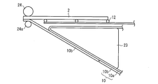
- FIG. 2 is a side view showing a structure in the vicinity of the nip rollers 24 and 24a.
- the laminated film 10 is half-cut by a half cutter 21, and the polarizing film 10 b is attached to the protective film via an adhesive layer (not shown). That is, before reaching the nip rollers 24 and 24a, the polarizing film 10b is cut by the half cutter 21 to a size preferable for bonding with the liquid crystal panel 2. On the other hand, the protective film 10a is not cut.
- the protective film 10a is peeled off by the knife edge 23.
- the knife edge 23 has a substantially triangular shape as a side surface thereof, and the side surface shape is smooth with no corners.
- the bottom surface (pressing surface) of the knife edge 23 is provided with an inclination and is disposed along the conveying direction of the protective film 10a.
- the knife edge 23 has a small frictional force with the protective film 10a, and is surface-treated with a member that allows the protective film 10a to be easily peeled off from the adhesive layer, such as diamond-like carbon.
- the protective film 10 a moves following the knife edge 23, is peeled off from the laminated film 10 at the tip of the knife edge 23, is removed, and is then wound around the winding unit 25.
- a metal material, a resin material, or the like can be applied, and is not particularly limited.
- stainless steel, aluminum, a resin material, and the like are recommended in terms of corrosion resistance, and specifically, SUS304, SUS420. Etc.
- the winding unit 25 is a device that winds the protective film 10a, and has the same basic structure as that of the unwinding unit 1 and 1a except that it is used for winding. In addition, the structure provided with the two winding parts similarly to the unwinding part 1 * 1a may be sufficient.
- the nip rollers 24 and 24a are for bonding the liquid crystal panel 2 transported by the transport mechanism 12 and the polarizing film 10b (or 20b) by pressure bonding.
- the pressure at the time of bonding by the nip rollers 24 and 24a can be adjusted as appropriate.
- the liquid crystal panel 2 having the polarizing film 10b bonded to the lower surface is transported to the reversing unit 26 by the transport mechanism 12.
- the reversing unit 26 is a member that reverses the liquid crystal panel, and may be designed with a known structure such as a robot arm.
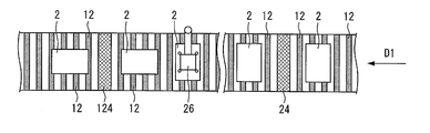
- FIG. 3 is a plan view showing the manufacturing system 100 toward the transport mechanism 12.
- the liquid crystal panel is transported in a straight line direction, which is different from the manufacturing system in the transport direction that bends at right angles such as the L-shaped direction. .
- the conveyance mechanism 12 can be arrange
- the structure of the manufacturing system 100 can be designed into a structure along a straight line, and the manufacturing system excellent in area efficiency can be provided. Since the optical display device is normally manufactured in a clean room, and the manufacturing cost of the clean room is high, the manufacturing system 100 having excellent area efficiency is useful.
- the reversing part 26 is provided with a suction part.
- FIG. 3 shows a state in which the upper surface of the liquid crystal panel 2 is sucked by the suction part of the reversing part 26.
- the adsorbing unit only needs to be able to adsorb and desorb the liquid crystal panel 2, and the reversing unit 26 uses an air suction type adsorbing unit. After the liquid crystal panel 2 is attracted, the liquid crystal panel 2 is reversed by the robot arm of the reversing unit 26. In the inverted liquid crystal panel 2, the polarizing film 10 b bonded to one side is located on the upper surface of the liquid crystal panel 2.
- the reversing unit 26 reverses the liquid crystal panel 2 and also changes the direction along the transport direction of the liquid crystal panel 2.
- the liquid crystal panel 2 is rectangular, and first, the short side is transported along the transport direction, and the polarizing film 10 b is bonded to the lower surface of the liquid crystal panel 2. Thereafter, the liquid crystal panel 2 is reversed by the reversing unit 26 so that the long side of the liquid crystal panel 2 is along the transport direction.
- the polarizing film used in the manufacturing system 100 has the absorption axis arranged in the film transport direction, and thus the absorption axes of the polarizing film bonded to both surfaces of the liquid crystal panel 2 are orthogonal to each other.
- the protective film is formed from the laminated film 110 that is unwound from the unwinding portion 101 in the second bonding mechanism, similarly to the first bonding mechanism. 110a is peeled off. Thereafter, the polarizing film 110b is bonded to the lower surface of the liquid crystal panel 2 through the adhesive layer by the nip rollers 124 and 124a.
- an optical display device in which the polarizing film is bonded to both surfaces of the liquid crystal panel 2 is manufactured. Since two polarizing films are bonded together from the lower surface to both surfaces of the liquid crystal panel 2, the rectifying environment around the manufacturing system 100 is not hindered.
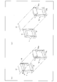
- FIG. 4A is a perspective view showing a state in which the unwinding portions 1 and 1a are installed in the manufacturing system 100.
- FIG. For convenience of explanation, other members such as the film connecting portion 3 are not shown.
- the unwinding part 1 * 1a in this invention is demonstrated, it is the same also about the unwinding part 101 * 101a.
- the unwinding part 1 and the unwinding part 1a according to the present invention can move horizontally along the winding core direction of the polarizing film 10b.
- the core direction of the polarizing film is the core direction of the original roll R1 in the unwinding section 1, and the core direction of the original roll R1a in the unwinding section 1a, both of which are indicated by the core direction D2. Yes.
- the remaining amount of the raw roll R1 is in a reduced state.
- FIG. 4B is a perspective view showing a state in which the unwinding portion 1 is moved horizontally along the core direction D2.
- the unwinding unit 1 is moved by a slide type moving mechanism 27 provided at the bottom of the unwinding unit 1.
- the state of FIG. 4B is in other words a state in which the unwinding part has been moved along the core direction D2. it can.
- the unwinding part 1 can also move in the core direction of the polarizing film in the opposite direction to the core direction D2.
- the unwinding unit 1 can be moved by the moving mechanism 27 toward the unwinding unit 1a or away from the unwinding unit 1a.
- the unwinding part 1a also includes a moving mechanism 27a at the bottom, and can move similarly to the unwinding part 1.
- the unwinding part 1 is movable along the core direction D2, and unlike a laminating machine having a turret, the unwinding part 1 does not move upward. For this reason, it is not necessary to secure a space in which the unwinding unit 1 moves between the unwinding unit 1 and the transport mechanism 12, and the range in which the unwinding unit 1 moves can be reduced. The same applies to the unwinding portion 1a. For this reason, the manufacturing system 100 reduced in size can be provided.
- the manufacturing system 100 includes the unwinding portions 1 and 1a, and when the remaining amount of the original roll R1 is almost exhausted, the laminated film 10 and the original roll R1a unwound from the original roll R1. Can be easily connected to the laminated film 20 unwound from the wire.
- the polarizing film 10b and the polarizing film 20b are connected.
- this connection can be performed by an operator, and can also be performed using the film connecting portions 3 and 13 as described later.
- the unwinding sections 1 and 1a are arranged side by side along the transport direction so that the direction of the core of the original roll installed in each is orthogonal to the transport direction of the liquid crystal panel 2 by the transport mechanism 12. Yes.
- the distance between the unwinding portion 1 and the unwinding portion 1a is preferably 0.5 m or more and 5 m or less from the viewpoint of promptly replacing the raw roll in the unwinding portions 1 and 1a. More preferably, it is 1 m or more and 3 m or less.
- the distance between the unwinding part 1 and the unwinding part 1a refers to the distance between the unwinding parts 1 and 1a that connect the locations where the cores of the raw rolls R1 and R1a are installed.
- FIG. 5 is a perspective view showing the film connecting portion 3 and the cutting machine 7.
- the film connecting part 3 includes adsorption parts 4 and 4a and a cutting and bonding part 5.
- the adsorption parts 4 and 4a are members for adsorbing and holding the polarizing film.
- the adsorbing parts 4 and 4a have a flat plate shape and are provided with a plurality of adsorbing mechanisms 9 on the surface thereof.
- the adsorption mechanism 9 is not particularly limited as long as the polarizing film can be adsorbed, and a configuration in which the polarizing film is adsorbed by sucking air with a pump can be adopted.
- the cutting and bonding unit 5 is rotatable and has a plurality of surfaces. Specifically, the cutting and bonding unit 5 has a polygonal shape and is rotatable. Furthermore, as a preferable form, it is movable in the vertical direction with respect to the laminated film 10 (polarizing film 10b). By being movable in the vertical direction with respect to the laminated film 10 (polarizing film 10b), when the cutting and bonding part 5 rotates, the cutting and bonding part 5 is perpendicular to the laminated film 10 (polarizing film 10b). And it can move to the direction away from the polarizing film 10b, and can rotate after a movement.
- the cutting and bonding part 5 can move in a direction perpendicular to the polarizing film 10b and close to the polarizing film 10b to return to the original position. Thereby, it is possible to avoid reliably that the corner
- the cutting bonding part 5 is a polygonal column shape, and as shown also in FIG. 6, although the cutting support surface 5a and the bonding surfaces 5b and 5c are provided in the three surfaces, a cutting support surface and / or a bonding are provided.
- a mating surface may be further provided.
- the structure which is equipped with the cutting support surface on one surface and the bonding surface on three or four surfaces can be given, the cutting support surface is on two surfaces, and the bonding surface is on three or four surfaces.
- a configuration provided may also be mentioned. If the corner
- the length (length in the width direction of the polarizing film 10b) of 200 mm or more and 2000 mm or less can be set to a width of 10 mm or more and 300 mm or less (length in the conveyance direction of the polarizing film 10b).
- FIG. 6 is a perspective view showing the cutting and bonding part 5.
- FIG. 6 shows a state in which the cutting and bonding part 5 of FIG. 5 is rotated by 1/3 turn clockwise.
- the cutting and bonding part 5 has a cutting support surface 5a and two or more cutting support surfaces 5a and bonding surfaces 5b.
- the cutting support surface 5a supports the polarizing film 10b along the width direction of the polarizing film 10b (laminated film 10).
- disconnection support surface 5a and the bonding surface 5b have the adsorption
- a groove-shaped opening 6 is formed in the cutting support surface 5a, and the blade portion of the cutting machine 7 provided in the cutting bonding section 5 shown in FIG. Since the opening 6 is formed, the cutting machine 7 can be reliably passed along the width direction of the polarizing film 10b, and the polarizing films 10b and 20b are connected (connection of the laminated films 10 and 20). It can be done more accurately.
- the cutting machine 7 can employ a known cutter and can easily cut the polarizing film 10b, and therefore preferably has a round blade shape. Moreover, the cutting machine 7 is supported by the base part 8 which can be driven in the width direction of the polarizing film 10b.
- the bonding surfaces 5b and 5c have the same configuration, and are provided with a plurality of suction mechanisms 9 in the same manner as the suction portions 4 and 4a.
- the single-sided adhesive tape (connecting material) 5d is arrange
- the single-sided adhesive tape 5d only needs to be able to bond polarizing films (laminate films) together, and a known single-sided adhesive tape can be used.
- film materials for tape include polyethylene terephthalate film (PET film), cellulose, Japanese paper, aluminum, non-woven fabric, polytetrafluoroethylene, polyvinyl chloride, polyvinylidene chloride, polycarbonate, polyurethane, ABS resin, polyester, polystyrene, Examples thereof include polyethylene, polypropylene, polyacetal resin, polylactic acid, polyimide, polyamide, and the like.
- Adhesives used for the adhesive layer include acrylic, epoxy, polyurethane, synthetic rubber, EVA, silicone, and chloride.
- the adhesive include vinyl, chloroprene rubber, cyanoacrylate, isocyanate, polyvinyl alcohol, and melamine resin.
- the film connecting part 3 is arranged so as to face the polarizing film 10b (the film connecting part 13 is arranged so as to face the protective film 10a). For this reason, in FIG. 1, since the polarizing film 10b is arrange
- the film connecting part 13 has the same structure as the film connecting part 3. As shown in FIG. 1, the film connecting portions 3 and 13 are arranged so that the suction mechanisms 9 of the suction portions 4 (the suction portions 4 a) provided in the film connecting portions 3 and 13 face each other. Moreover, the film connection parts 3 and 13 are arranged with the passage positions of the laminated film 10 and the laminated film 20 interposed therebetween. In addition, the manufacturing system 100 provided with the film connection part 3 * 13 is a preferable form in this Embodiment, and can also be set as the form which is not provided with the film connection part 3 * 13. The film connecting portions 103 and 113 have the same configuration as the film connecting portions 3 and 13.
- the laminated film 10 is unwound from the unwinding portion 1 (unwinding step). Thereafter, as shown in FIG. 2, the polarizing film 10b and the adhesive layer are half-cut by the half cutter 21, and the protective film 10a is peeled by the knife edge 23 (peeling step). Further, the polarizing film 10b and the liquid crystal panel 2 are bonded together by the nip rollers 24 and 24a being pressed against the lower surface of the liquid crystal panel 2 via the adhesive layer (bonding step). The peeled protective film 10a is wound and collected by a winding unit (not shown).
- the liquid crystal panel 2 having the polarizing film 10b bonded to the lower surface is reversed by the reversing unit 26 and moved so that the short side of the liquid crystal panel 2 along the transport direction is perpendicular to the transport direction. (Reversal process).
- the surface where the liquid crystal panel is not bonded becomes the lower surface of the liquid crystal panel 2 by the reversal process.
- the remaining amount of the roll of the laminated film 10 held by the unwinding unit 1 decreases.
- the connection process which connects polarizing films is demonstrated. The same applies to the unwinding unit 101.
- the connecting step the laminated film 10 is cut and wound from the laminated film 10 left on the line side (separated from the original roll R1 of the unwinding portion 10) and the original roll R1a installed in the unwinding portion 1a.
- This is a step of connecting the laminated film 20 that has been taken out. Examples of the connecting step include (1) a technique by an operator and (2) a technique using the film connecting portions 3 and 13.
- the conveyance speed of the laminate film 10 is set to 0 m / min. (After stopping the laminated film 10), the operator cuts the laminated film 10 (polarizing film 10b). Next, after unwinding the laminated film 20 from the unwinding part 1a and cutting the end part of the laminated film 20, for example, a method of connecting using the above-described single-sided adhesive tape 5d can be used.
- the two unwinding portions of the unwinding portions 1 and 1a are provided in parallel. Therefore, without replacing the original roll R1 with a new roll, the polarizing films R1a can be used to immediately connect the polarizing films (laminate films), and the laminated film 20 can be quickly unwound. it can.
- the original roll roll can be replaced at the unwinding unit that is vacant during operation. Can be reduced. As a result, it is possible to shorten the manufacturing time of the optical display device.
- the raw roll R1 of the unwinding unit 1 is replaced with a new roll while the laminated film 20 is unwound. When the remaining amount of the laminated film 20 is reduced, it is of course possible to connect the laminated film 20 and the laminated film 10 in the same manner.
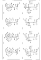
- FIG. 7 is a process diagram illustrating a connection process by the manufacturing system 100.
- the remaining amount of the raw fabric roll R1 decreases, and the conveying speed of the laminated film 10 (polarizing film 10b) is reduced to 0 m / min.
- the adsorbing parts 4 and 4a and the cutting and bonding part 5 are moved in the vertical direction with respect to the polarizing film 10b (laminated film 10).
- the polarizing film 10b is sucked and held by the suction mechanism 9 of the suction parts 4 and 4a (suction process).
- the cutting support surface 5a is in contact with the polarizing film 10b.
- the cutting machine which is not shown in figure is moved along the opening 6, and the laminated
- the cut bonding part 5 is moved in the direction perpendicular to the polarizing film 10b and away from the polarizing film 10b (left side in the figure). Then, it is rotated clockwise by 1/3 turn and moved in a direction perpendicular to the polarizing film 10b and close to the polarizing film 10b (right side in the figure).
- the single-sided adhesive of the bonding surface 5b is covered so that the cutting line of the polarizing film 10b facing the single-sided adhesive tape 5d (not shown) may be covered (beyond a cutting line).
- the tape 5d is bonded together (bonding process).
- the said cutting line shows the edge
- the single-sided adhesive tape 5d is arranged so as to cover the cutting line, that is, the single-sided adhesive tape 5d is arranged in a portion where the polarizing film 10b does not exist beyond the cutting line of the polarizing film 10b. ing.
- the single-sided adhesive tape 15d is adhered to the protective film 20a in the same manner as in FIGS. 7D to 7E with respect to the laminated film 20.
- the same members as those described above are given the same names, and the description thereof is omitted.
- the laminated film 20 is unwound from the unwinding portion 1a, and a cutting machine (not shown) is moved along the opening formed in the cutting support surface 15a to cut the laminated film 20 as in FIG. To do.
- the cut bonding part 15 is moved in a direction perpendicular to the protective film 20a and away from the protective film 20a (right side in the figure).
- it is rotated counterclockwise by 1/3 round and moved in a direction perpendicular to the protective film 20a and close to the protective film 20a (left side in the figure).
- the single-sided adhesive tape 15d can be affixed so that the cutting line of the protective film 20a facing the single-sided adhesive tape 15d of the bonding surface 15b may be covered.
- the protective films 10a and 20a that protect the polarizing films 10b and 20b and the polarizing films 10b and 20b are connected to each other.
- the part beyond the cutting line can be rephrased as a part not bonded to the polarizing film 10b / protective film 20a.
- the film connecting portion 3 is brought close to the film connecting portion 13, but the film connecting portion 13 may be brought close to the film connecting portion 3, and the film connecting portions 3 and 13 are brought close to each other. May be.
- the film connecting portions 3 and 13 are perpendicular to the polarizing film 10b and the protective film 20a, respectively. Move away. Thereafter, the cutting and bonding unit 5 is rotated counterclockwise by 3, and the cutting and bonding unit 15 is rotated clockwise by 3. Thereby, the cutting support surface 5a faces the polarizing film 10b side, and the cutting support surface 15a faces the protective film 20a side (position in FIG. 7 (h)). Thereby, a series of processes are completed.
- the bonding surfaces 5c and 15c are provided with a single-sided adhesive tape 5d and 15d adsorbed in advance.
- the polarizing film is adsorbed, cut, and bonded in a shorter time and more accurately than the connecting step by the operator. Is preferable.
- the time could be reduced to 1 minute or less.
- the manufacturing system 100 when only the unwinding part 1 is used, the unwinding part 1a is not used, and the film connecting parts 3 and 13 are not used, the operator adds a new raw roll R1 to the unwinding part 1. It is necessary to connect the laminated film 10 after installing. In this case, the connecting process requires about 30 minutes. For this reason, it is clear that the manufacturing system 100 according to the present embodiment is useful.
- FIG. 8 is a side view showing the manufacturing system 200.
- the manufacturing system 200 differs from the manufacturing system 100 in that the film holding and cutting portions 33 and 133 are replaced with the film connecting portions 3 and 103, and the first connecting material is replaced with the film connecting portions 13 and 113. Bonding portions 36 and 136 are provided.
- maintenance cutting part is abbreviate
- the manufacturing system 200 is further provided with the 2nd connection material bonding part 36a * 136a.
- the film holding and cutting part 33 and the first connecting material bonding part 36 are a laminated film 10 (first polarizing film) unwound from the unwinding part 1 and a laminated film which is a polarizing film unwound from the unwinding part 1a. It arrange
- the film holding / cutting part 33 is arranged so as to face the laminated film 10
- the first connecting material bonding part 36 is arranged so as to face the laminated film 20.
- the manufacturing system 200 is equipped so that the 2nd connection material bonding part 36a may be arrange
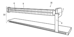
- FIG. 9 is a perspective view showing the film holding / cutting portion 33.
- the film holding / cutting unit 33 includes a film holding unit 35 and a cutting machine 7, and the cutting machine 7 is supported by the base 8.
- the film holding unit 35 includes the suction mechanism 9 in the film holding unit 35 facing the laminated film 10, and the film holding unit 35 has a groove-shaped opening 6 formed therein.
- the suction mechanism 9 is the same as that provided in the film connecting portion 3.
- an adsorption mechanism 9 that adsorbs or desorbs the laminated film 10 is provided on the surface on which the opening 6 is formed.
- the structure is not limited to this structure, and the film holding unit 35 may not include the suction mechanism 9 and may include the suction units 4 and 4a as in the film connection unit 3.
- the opening 6 is formed horizontally along the width direction of the laminated film 10 (polarizing film 10 a), and the cutting machine 7 cuts the laminated films 10 and 20 along the opening 6.
- the suction mechanism 9 is formed in the film holding unit 35 with the opening 6 as a boundary.
- the laminated film 10 is divided into two parts by cutting the laminated film 10.
- the adsorption mechanism 9 can control adsorption or desorption for each adsorption mechanism divided into two with the opening 6 as a boundary.
- the laminated film 10 in the unwinding direction and the laminated film in the direction opposite to the unwinding direction 10 can be selectively adsorbed or desorbed. Thereby, for example, when the laminated film 10 is cut, only the laminated film 10 in the unwinding direction is detached and only the laminated film 10 in the unwinding direction is adsorbed to the film holding unit 35. .
- the laminated film 20 in the direction opposite to the unwinding direction is moved to the position where the laminated film 10 in the direction opposite to the unwinding direction is adsorbed.
- the film 10 and the laminated film 20 in the direction opposite to the unwinding direction can be in a state in which the cut surfaces face each other.
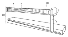
- FIG. 10 is a perspective view showing a film holding / cutting portion 233 which is a modification of the film holding / cutting portion 33.
- the opening 6 is formed in the film holding part 235 in an oblique direction.
- the cutting machine 7 cuts both the laminated film 10 and the laminated film 20 in an oblique direction with respect to the width direction of the laminated film 10.
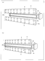
- FIG. 11 (a) and 11 (b) are perspective views showing the first connecting material bonding portion 36.
- FIG. The first connecting material bonding part 36 includes adsorption parts 4 and 4 a and a connecting material holding part 37.
- the connecting material holding part 37 includes the suction mechanism 9 and holds the single-sided adhesive tape (connecting material) 35d by suction.
- the adsorbing portions 4 and 4 a include an adsorbing mechanism 9 that adsorbs or desorbs the laminated film 20.
- the adsorbing portions 4 and 4a can independently control adsorption or desorption, and among the cut laminated films 20, the laminated film 20 in the unwinding direction and the laminated film 20 in the direction opposite to the unwinding direction are selectively used. Can be adsorbed or desorbed.
- the laminated film 20 in the unwinding direction is adsorbed or desorbed by the adsorption unit 4, and the laminated film 20 in the direction opposite to the unwinding direction is adsorbed or desorbed by the adsorption unit 4a.
- connection material bonding part 36 is movable with respect to the laminated
- the connecting material holding part 37 is arranged away from the laminated film 20 as compared with the adsorbing parts 4 and 4a, and the adsorbing parts 4 and 4a are arranged close to the laminated film 20. Has been.
- FIG. 11B shows a state in which the connecting material holding portion 37 is close to the laminated film 20, and the connecting material is held so that the suction portion 4, the single-sided adhesive tape 35 d and the suction portion 4 a are located in the same plane.
- a portion 37 is arranged.
- the single-sided adhesive tape 35 d can be bonded to the laminated film 20 by the connecting material holding part 37 moving in the direction of the laminated film 20.
- maintenance part 37 has a substantially triangular prism shape, and is further provided with two surfaces which hold
- a single-sided adhesive tape 35d can be held in advance on these two surfaces, and the single-sided adhesive tape 35d is again applied to the laminated film without replenishing the single-sided adhesive tape 35d by rotating the connecting material holding portion 37.
- the laminated films can be connected to each other (second connecting step described later).
- the 2nd connection material bonding part 36a has the structure similar to the 1st connection material bonding part 36, and is provided with the adsorption
- the laminated film 10 in the unwinding direction is adsorbed or desorbed by the adsorption unit 4, and the laminated film 10 in the direction opposite to the unwinding direction is adsorbed or desorbed by the adsorption unit 4a.
- FIG. 12 is a process diagram showing a connection process by the manufacturing system 100.
- the transport speed of the laminated film 10 (polarizing film 10b) is set to 0 m / min.
- the film holding unit 35 is moved in the vertical direction with respect to the polarizing film 10 b (laminated film 10), and the polarizing film 10 b is adsorbed by the adsorbing mechanism 9.
- one end of the laminated film 20 is fixed to the film adsorption roll 16a, and the adsorption portions 4 and 4a are moved relative to the laminated film 20, and the protective film 10a is adsorbed by the adsorption mechanism 9 of the adsorption portions 4 and 4a. And hold (adsorption process).
- the film adsorption roll 16a is a roller that adsorbs and holds the laminated film, and is used to hold one end of the supplementary laminated film (polarizing film).
- the supplementary laminated film is the laminated film 20, but when the laminated film 10 is connected to the laminated film 20, the film adsorbing roller is arranged so that one end of the laminated film 10 is held by the film adsorbing roller. Is placed.
- the adsorbing portions 4 and 4a are moved toward the laminated film 10 so that the laminated film 10 and the laminated film 20 are adjacent to each other.
- the cutting machine 7 is moved along the opening to cut the laminated films 10 and 20.
- the adsorption of the adsorption mechanism 9 of the film holding unit 35 that adsorbs the laminated film 10 (lower laminated film 10) opposite to the unwinding direction is released, and this lamination is performed. Only the film 10 is detached and separated from the film holding portion 35.
- the suction of the suction mechanism 9 of the suction portion 4 that sucks the laminated film 20 (upper laminated film 20) in the unwinding direction is released, and only this laminated film 20 is detached and separated from the suction portion 4.
- the suction part 4 a that sucks the laminated film 20 (lower laminated film 20) in the direction opposite to the unwinding direction is moved toward the film holding part 35.
- the laminated film 20 in the direction opposite to the unwinding direction is moved to the position where the laminated film 10 in the direction opposite to the unwinding direction has been arranged, and the laminated film 10 in the direction of unwinding and the laminated film in the direction opposite to the unwinding direction. 20 is in a state where the cut surfaces face each other.
- the laminated film 20 in the direction opposite to the unwinding direction is adsorbed by the adsorption mechanism 9 of the film holding unit 35, and the adsorption by the adsorption unit 4a is released.
- maintenance part 37 As shown in FIG.12 (d), by moving the connection material holding
- a single-sided adhesive tape 35d is pasted across the cutting line of both laminated films.
- maintenance part 37 are moved to the reverse direction with the laminated film connected.
- multilayer film are unwound from the unwinding part 1a, and are moved to a conveyance direction.
- the conveyance is stopped, and the adhering part 4 of the second connecting material bonding part 36a adsorbs the laminated film 10 in the unwinding direction.
- the laminated film 20 in the direction opposite to the unwinding direction is adsorbed by the adsorbing part 4a of the second connecting material bonding part 36a.
- the second connecting material bonding portion 36a is moved toward the opposite surface of the laminated film on which the single-sided adhesive tape 35d is bonded by the connecting material holding portion 37.
- the connecting material holding part 37a moves toward the cutting line of the connected polarizing film, and the single-sided adhesive tape 35d held by the connecting material holding part 37a is pasted across the cutting line on the reverse surface of the laminated film. .
- the single-sided adhesive tape 35d is bonded on both surfaces, and the laminated films 10 and 20 are connected in a state having sufficient strength.
- the adsorbing part 4 As shown in FIG. 12 (h), finally, the adsorbing part 4, the connecting material holding part 37a and the adsorbing part 4a of the second connecting material bonding part 36a are separated from the connected laminated film, and the connected laminated film The conveyance is started.
- the production system according to the present invention includes two unwinding portions in each of the two bonding mechanisms, and further a laminated film (polarizing film) unwound from the two unwinding portions included in the same bonding mechanism. ) Connect each other.
- the process (manufacturing method of the optical display device) using the manufacturing system of the present invention includes (1) unwinding process, (2) connecting process, and (3) replacing process.
- the unwinding step is a step of unwinding the laminated film (polarizing film) from the unwinding portion
- the connecting step is between the laminated films (polarizing film) as described with reference to FIGS. Is a step of connecting
- the connecting step may be a step in which the operator cuts the laminated film unwound from the first unwinding portion and the second unwinding portion, and bonds both the laminated films with a single-sided adhesive tape.
- the unwinding portions 1 and 101 are moved horizontally along one core direction of the original rolls R1 and R101, and (2) the original rolls R1 and R101 are moved to new original rolls. (3) The unwinding portions 1 and 101 are moved horizontally along the other core direction of the new original fabric roll, and the unwinding portions 1 and 101 are returned to their original positions. .
- the unwinding process, the connecting process, and the replacing process are performed using the unwinding units 1, 1 a, 101, and 101 a, whereby the replacement time of the original roll can be efficiently shortened.
- FIG. 13 is a plan view showing the operation of the unwinding portions 1, 1 a, 101, 101 a of the manufacturing system 200
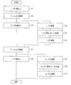
- FIG. 14 is a flowchart showing a manufacturing method using the manufacturing system 200.
- the manufacturing system 200 starts operation in a state where the raw fabric rolls are installed in the unwinding sections 1, 1 a, 101, 101 a (START in FIG. 14).
- the laminated films 10 and 110 are unwound from the unwinding portions 1 and 101, respectively (S1: first unwinding step in FIG. 14).
- S1 first unwinding step in FIG. 14.
- the laminated films 10 and 20 and the laminated films 110 and 120 are connected (S2 in FIG. 14: first connection). Process).
- the laminated films 20 and 120 are unwound from the unwinding portions 1a and 101a (S3 in FIG. 14: second unwinding step), and the manufacture of the optical display device is continued.
- the first replacement process is performed as S4 to S6.
- the unwinding portions 1 and 101 are horizontally movable along one core direction of the laminated films 10 and 110 (S4 in FIG. 14).
- the raw rolls R1 and R101 (polarizing film) of the unwinding portions 1 and 101 are replaced with new raw rolls (polarizing film) (S5 in FIG. 14).
- the unwinding portions 1 and 101 are allowed to move horizontally along the other core direction of the new original fabric roll (polarizing film) (S6 in FIG. 14, FIGS. 13B to 13C). Thereby, the unwinding parts 1 and 101 are returned to the original positions.
- the laminated films 20 and 10 and the laminated films 120 and 110 are connected (S7 in FIG. 14: second connecting step). Thereafter, the laminated films 10 and 110 are unwound from the unwinding portions 1 and 101 (S8 in FIG. 14: third unwinding step), and the manufacture of the optical display device is continued.
- a second exchange process is performed as S9 to S11 in order to exchange a new raw roll for the unwinding portions 1a and 101a.
- the unwinding portions 1a and 101a are horizontally movable along one core direction of the laminated films 20 and 120 (S9 in FIG. 14).
- the raw rolls R1a and R101a (polarizing film) of the unwinding portions 1a and 101a are replaced with new raw rolls (polarizing film) (S10 in FIG. 14).
- the unwinding portions 1a and 101a are moved horizontally along the other core direction of the new original fabric roll (polarizing film) (S11 in FIG. 14, FIG. 13 (d) to (a)).
- the unwinding part 1a * 101a is returned to the original position.
- movement of the unwinding part was demonstrated, it is also possible to return to S1 from S11 and to continue manufacture of an optical display apparatus.
- S3 and S4 to S6 are performed in parallel, and S8 and S9 to S11 are performed in parallel. Therefore, while unwinding the laminated film (polarizing film), the raw roll of the laminated film (polarizing film) can be exchanged, and the polarizing films can be quickly connected. Therefore, the time for stopping the manufacturing system can be suppressed, and the optical display device can be manufactured with a short tact time.
- the present invention is not limited to the above-described embodiments, and various modifications can be made within the scope of the claims, and the technical means disclosed in different embodiments can be appropriately combined. Such embodiments are also included in the technical scope of the present invention.
- the number of guide rollers in the manufacturing system and the arrangement of the unwinding unit, the winding unit, the film connecting unit, and the transport mechanism are not limited to the illustrated arrangement.
- the transport mechanism has a linear liquid crystal panel transport direction.
- the structure of the manufacturing system can be designed to be a structure along the straight line.
- An efficient manufacturing system can be provided.
- the first polarizing film and the second unwinding in which the film holding and cutting part and the first connecting material bonding part are the polarizing films unwound from the first unwinding part. It arrange
- the second connecting material bonding portion is disposed toward the first polarizing film
- the film holding / cutting portion includes a film holding portion and a cutting machine
- the film holding portion is And an adsorption mechanism that adsorbs or desorbs the first polarizing film
- the cutting machine cuts both the first polarizing film and the second polarizing film
- the first connecting material bonding portion is a second one.
- Sucking polarizing film Or it has the connection part holding part which hold
- the said 2nd connection material bonding part is the said cutting
- Pasting across the cutting line of the polarizing film together with an adsorbing mechanism equipped with an adsorbing mechanism that adsorbs or desorbs the first polarizing film in the unwinding direction and the second polarizing film in the direction opposite to the unwinding direction.
- Each of the first and second polarizing films in the unwinding direction and the second polarizing film in the opposite direction to the unwinding direction are cut by a cutting machine.
- Opposite of both polarizing films in which the connecting material is pasted across the cutting line of both polarizing films by the first connecting material bonding portion and the connecting material is bonded by the first connecting material bonding portion in the opposed state.
- On the surface, by the second connecting material bonding part It is preferable to be bonded the connecting member beyond the cutting line of the polarizing film.
- the manufacturing method of the optical display device which concerns on this invention is a manufacturing method of the optical display apparatus using the said manufacturing system of an optical display apparatus, Comprising: The 1st unwinding process which unwinds a polarizing film from a 1st unwinding part.
- the first unwinding portion can be moved horizontally along one core direction of the polarizing film, and the polarizing film of the first unwinding portion is newly polarized.
- the first exchange step for exchanging the film and moving the first unwinding portion horizontally along the other core direction of the polarizing film, the polarizing film unwound from the second unwinding portion, and the first winding A second connecting step of connecting the polarizing film unwound from the exit portion; During the third unwinding step of unwinding the polarizing film from the unwinding portion and the third unwinding step, the second unwinding portion can be moved horizontally along one core direction of the polarizing film, A second exchanging step of exchanging the polarizing film of the unwinding part with a new polarizing film and allowing the second unwinding part to move horizontally along the other core direction of the polarizing film.
- the present invention when the optical display device is manufactured, the polarizing films can be quickly connected, and the manufacturing time of the optical display device can be shortened. Therefore, the present invention can be used in the field of manufacturing an optical display device.
Landscapes
- Physics & Mathematics (AREA)
- Nonlinear Science (AREA)
- Liquid Crystal (AREA)
- Engineering & Computer Science (AREA)
- Manufacturing & Machinery (AREA)
- Chemical & Material Sciences (AREA)
- Crystallography & Structural Chemistry (AREA)
- General Physics & Mathematics (AREA)
- Optics & Photonics (AREA)
- Polarising Elements (AREA)
- Devices For Indicating Variable Information By Combining Individual Elements (AREA)
Priority Applications (2)
| Application Number | Priority Date | Filing Date | Title |
|---|---|---|---|
| KR1020147000298A KR101885943B1 (ko) | 2011-06-09 | 2012-06-06 | 광학 표시 장치의 제조 시스템 및 광학 표시 장치의 제조 방법 |
| CN201280027910.8A CN103620485B (zh) | 2011-06-09 | 2012-06-06 | 光学显示装置的制造系统以及光学显示装置的制造方法 |
Applications Claiming Priority (2)
| Application Number | Priority Date | Filing Date | Title |
|---|---|---|---|
| JP2011129408A JP5667522B2 (ja) | 2011-06-09 | 2011-06-09 | 光学表示装置の製造システムおよび光学表示装置の製造方法 |
| JP2011-129408 | 2011-06-09 |
Publications (1)
| Publication Number | Publication Date |
|---|---|
| WO2012169553A1 true WO2012169553A1 (ja) | 2012-12-13 |
Family
ID=47296112
Family Applications (1)
| Application Number | Title | Priority Date | Filing Date |
|---|---|---|---|
| PCT/JP2012/064599 Ceased WO2012169553A1 (ja) | 2011-06-09 | 2012-06-06 | 光学表示装置の製造システムおよび光学表示装置の製造方法 |
Country Status (5)
| Country | Link |
|---|---|
| JP (1) | JP5667522B2 (enExample) |
| KR (1) | KR101885943B1 (enExample) |
| CN (1) | CN103620485B (enExample) |
| TW (1) | TWI554381B (enExample) |
| WO (1) | WO2012169553A1 (enExample) |
Families Citing this family (3)
| Publication number | Priority date | Publication date | Assignee | Title |
|---|---|---|---|---|
| CN103439810B (zh) * | 2013-08-14 | 2016-08-31 | 张家港康得新光电材料有限公司 | 一种液晶显示器贴膜装置及使用该装置贴膜的方法 |
| JP2016038447A (ja) * | 2014-08-06 | 2016-03-22 | 住友化学株式会社 | 貼合装置、光学表示デバイスの生産システム、貼合方法、および光学表示デバイスの生産方法 |
| KR102470258B1 (ko) * | 2015-12-22 | 2022-11-24 | 삼성디스플레이 주식회사 | 표시 장치 및 그 제조 방법 |
Citations (2)
| Publication number | Priority date | Publication date | Assignee | Title |
|---|---|---|---|---|
| JPS61136850A (ja) * | 1984-12-06 | 1986-06-24 | Ckd Corp | フイルムの自動継ぎ方法 |
| JP2004361741A (ja) * | 2003-06-05 | 2004-12-24 | Fuji Photo Film Co Ltd | 光学フィルム貼付装置及び方法 |
Family Cites Families (16)
| Publication number | Priority date | Publication date | Assignee | Title |
|---|---|---|---|---|
| US3753833A (en) * | 1970-02-16 | 1973-08-21 | Butler Automatic Inc | Web supply apparatus |
| IT1269115B (it) * | 1994-06-16 | 1997-03-21 | Perini Fabio Spa | Dispositivo per il cambio automatico di bobine di materiale nastriforme |
| JP3132324B2 (ja) | 1995-02-07 | 2001-02-05 | 凸版印刷株式会社 | ロール状原反のターレット紙継ぎ制御方法 |
| JPH0977316A (ja) * | 1995-09-20 | 1997-03-25 | Nippon Reliance Kk | ウェブ自動継ぎ装置 |
| JP3706059B2 (ja) * | 2001-11-16 | 2005-10-12 | 王子エンジニアリング株式会社 | スプライサ装置および同制御方法 |
| JP5014361B2 (ja) * | 2002-06-28 | 2012-08-29 | 富士フイルム株式会社 | 偏光板貼合方法及び装置 |
| KR20040002796A (ko) * | 2002-06-28 | 2004-01-07 | 후지 샤신 필름 가부시기가이샤 | 편광판 점착방법 및 그 장치 |
| KR101010990B1 (ko) | 2006-10-17 | 2011-01-26 | 닛토덴코 가부시키가이샤 | 광학 부재 부착방법 및 그것을 이용한 장치 |
| JP4406043B2 (ja) * | 2008-04-16 | 2010-01-27 | 日東電工株式会社 | ロール原反セット、及びロール原反の製造方法 |
| TW201005355A (en) * | 2008-07-24 | 2010-02-01 | Hitachi High Tech Corp | Optical film adhesion device and production method of a display panel |
| JP5019633B2 (ja) * | 2008-10-16 | 2012-09-05 | 古河電気工業株式会社 | ウエハ加工用テープの長尺体 |
| JP4669070B2 (ja) * | 2009-05-21 | 2011-04-13 | 日東電工株式会社 | 光学表示装置の製造システム及び製造方法 |
| JP4503691B1 (ja) * | 2009-10-13 | 2010-07-14 | 日東電工株式会社 | 液層表示素子の連続製造方法及び装置 |
| JP4503689B1 (ja) * | 2009-10-13 | 2010-07-14 | 日東電工株式会社 | 液晶表示素子の連続製造方法及び装置 |
| JP4734515B1 (ja) * | 2009-12-28 | 2011-07-27 | 住友化学株式会社 | 光学表示装置の製造システムおよび当該光学表示装置の製造方法 |
| JP4751997B1 (ja) * | 2010-02-17 | 2011-08-17 | 住友化学株式会社 | 偏光フィルムの貼合装置およびこれを備える液晶表示装置の製造システム |
-
2011
- 2011-06-09 JP JP2011129408A patent/JP5667522B2/ja not_active Expired - Fee Related
-
2012
- 2012-06-06 CN CN201280027910.8A patent/CN103620485B/zh not_active Expired - Fee Related
- 2012-06-06 WO PCT/JP2012/064599 patent/WO2012169553A1/ja not_active Ceased
- 2012-06-06 KR KR1020147000298A patent/KR101885943B1/ko not_active Expired - Fee Related
- 2012-06-07 TW TW101120468A patent/TWI554381B/zh not_active IP Right Cessation
Patent Citations (2)
| Publication number | Priority date | Publication date | Assignee | Title |
|---|---|---|---|---|
| JPS61136850A (ja) * | 1984-12-06 | 1986-06-24 | Ckd Corp | フイルムの自動継ぎ方法 |
| JP2004361741A (ja) * | 2003-06-05 | 2004-12-24 | Fuji Photo Film Co Ltd | 光学フィルム貼付装置及び方法 |
Also Published As
| Publication number | Publication date |
|---|---|
| JP2012255940A (ja) | 2012-12-27 |
| KR101885943B1 (ko) | 2018-08-06 |
| TW201304933A (zh) | 2013-02-01 |
| JP5667522B2 (ja) | 2015-02-12 |
| CN103620485A (zh) | 2014-03-05 |
| CN103620485B (zh) | 2017-05-31 |
| KR20140044357A (ko) | 2014-04-14 |
| TWI554381B (zh) | 2016-10-21 |
Similar Documents
| Publication | Publication Date | Title |
|---|---|---|
| CN102520548B (zh) | 光学显示装置的制造系统 | |
| CN102405438B (zh) | 偏振膜的贴合装置以及具有该贴合装置的液晶显示装置的制造系统 | |
| JP5868734B2 (ja) | 光学表示パネルの連続製造方法および光学表示パネルの連続製造システム | |
| JP4885304B2 (ja) | 光学表示装置の製造システム | |
| JP5945143B2 (ja) | 光学フィルムロールセットおよび光学フィルムロールセットの製造方法。 | |
| TWI358564B (en) | Apparatus for sticking polarizing film and liquid | |
| CN102844702B (zh) | 偏振膜的贴合装置及具有该贴合装置的液晶显示装置的制造系统 | |
| JP6126257B2 (ja) | 光学フィルムロールセットおよび光学フィルムロールセットの製造方法 | |
| JP5667522B2 (ja) | 光学表示装置の製造システムおよび光学表示装置の製造方法 | |
| WO2012147793A1 (ja) | ナイフエッジおよびこれを含む液晶表示装置の製造システム | |
| CN102870148A (zh) | 光学膜贴合装置及贴合方法 | |
| JP2013033239A (ja) | ナイフエッジおよびこれを含む液晶表示装置の製造システム | |
| JP5969247B2 (ja) | 光学表示パネルの連続製造方法およびその連続製造システム、切替方法および繰出装置 | |
| JP2012118561A (ja) | 液晶表示装置の製造システムおよび製造方法 | |
| JP2014137577A (ja) | 光学表示装置の製造システム | |
| JP2014130285A (ja) | 光学表示装置の製造装置 | |
| JP2012198476A (ja) | 液晶表示装置の製造システム |
Legal Events
| Date | Code | Title | Description |
|---|---|---|---|
| 121 | Ep: the epo has been informed by wipo that ep was designated in this application |
Ref document number: 12796186 Country of ref document: EP Kind code of ref document: A1 |
|
| NENP | Non-entry into the national phase |
Ref country code: DE |
|
| ENP | Entry into the national phase |
Ref document number: 20147000298 Country of ref document: KR Kind code of ref document: A |
|
| 122 | Ep: pct application non-entry in european phase |
Ref document number: 12796186 Country of ref document: EP Kind code of ref document: A1 |