WO2012169553A1 - Manufacturing system for optical display device and method for manufacturing optical display device - Google Patents
Manufacturing system for optical display device and method for manufacturing optical display device Download PDFInfo
- Publication number
- WO2012169553A1 WO2012169553A1 PCT/JP2012/064599 JP2012064599W WO2012169553A1 WO 2012169553 A1 WO2012169553 A1 WO 2012169553A1 JP 2012064599 W JP2012064599 W JP 2012064599W WO 2012169553 A1 WO2012169553 A1 WO 2012169553A1
- Authority
- WO
- WIPO (PCT)
- Prior art keywords
- unwinding
- polarizing film
- film
- bonding
- polarizing
- Prior art date
Links
Images


Classifications
-
- B—PERFORMING OPERATIONS; TRANSPORTING
- B32—LAYERED PRODUCTS
- B32B—LAYERED PRODUCTS, i.e. PRODUCTS BUILT-UP OF STRATA OF FLAT OR NON-FLAT, e.g. CELLULAR OR HONEYCOMB, FORM
- B32B38/00—Ancillary operations in connection with laminating processes
- B32B38/18—Handling of layers or the laminate
-
- G—PHYSICS
- G02—OPTICS
- G02F—OPTICAL DEVICES OR ARRANGEMENTS FOR THE CONTROL OF LIGHT BY MODIFICATION OF THE OPTICAL PROPERTIES OF THE MEDIA OF THE ELEMENTS INVOLVED THEREIN; NON-LINEAR OPTICS; FREQUENCY-CHANGING OF LIGHT; OPTICAL LOGIC ELEMENTS; OPTICAL ANALOGUE/DIGITAL CONVERTERS
- G02F1/00—Devices or arrangements for the control of the intensity, colour, phase, polarisation or direction of light arriving from an independent light source, e.g. switching, gating or modulating; Non-linear optics
- G02F1/01—Devices or arrangements for the control of the intensity, colour, phase, polarisation or direction of light arriving from an independent light source, e.g. switching, gating or modulating; Non-linear optics for the control of the intensity, phase, polarisation or colour
- G02F1/13—Devices or arrangements for the control of the intensity, colour, phase, polarisation or direction of light arriving from an independent light source, e.g. switching, gating or modulating; Non-linear optics for the control of the intensity, phase, polarisation or colour based on liquid crystals, e.g. single liquid crystal display cells
- G02F1/1303—Apparatus specially adapted to the manufacture of LCDs
-
- B—PERFORMING OPERATIONS; TRANSPORTING
- B32—LAYERED PRODUCTS
- B32B—LAYERED PRODUCTS, i.e. PRODUCTS BUILT-UP OF STRATA OF FLAT OR NON-FLAT, e.g. CELLULAR OR HONEYCOMB, FORM
- B32B2457/00—Electrical equipment
- B32B2457/20—Displays, e.g. liquid crystal displays, plasma displays
- B32B2457/202—LCD, i.e. liquid crystal displays
-
- B—PERFORMING OPERATIONS; TRANSPORTING
- B32—LAYERED PRODUCTS
- B32B—LAYERED PRODUCTS, i.e. PRODUCTS BUILT-UP OF STRATA OF FLAT OR NON-FLAT, e.g. CELLULAR OR HONEYCOMB, FORM
- B32B37/00—Methods or apparatus for laminating, e.g. by curing or by ultrasonic bonding
- B32B37/14—Methods or apparatus for laminating, e.g. by curing or by ultrasonic bonding characterised by the properties of the layers
- B32B37/16—Methods or apparatus for laminating, e.g. by curing or by ultrasonic bonding characterised by the properties of the layers with all layers existing as coherent layers before laminating
- B32B37/18—Methods or apparatus for laminating, e.g. by curing or by ultrasonic bonding characterised by the properties of the layers with all layers existing as coherent layers before laminating involving the assembly of discrete sheets or panels only
- B32B37/182—Methods or apparatus for laminating, e.g. by curing or by ultrasonic bonding characterised by the properties of the layers with all layers existing as coherent layers before laminating involving the assembly of discrete sheets or panels only one or more of the layers being plastic
- B32B37/185—Laminating sheets, panels or inserts between two discrete plastic layers
-
- G—PHYSICS
- G02—OPTICS
- G02B—OPTICAL ELEMENTS, SYSTEMS OR APPARATUS
- G02B5/00—Optical elements other than lenses
- G02B5/30—Polarising elements
- G02B5/3025—Polarisers, i.e. arrangements capable of producing a definite output polarisation state from an unpolarised input state
- G02B5/3033—Polarisers, i.e. arrangements capable of producing a definite output polarisation state from an unpolarised input state in the form of a thin sheet or foil, e.g. Polaroid
-
- G—PHYSICS
- G02—OPTICS
- G02F—OPTICAL DEVICES OR ARRANGEMENTS FOR THE CONTROL OF LIGHT BY MODIFICATION OF THE OPTICAL PROPERTIES OF THE MEDIA OF THE ELEMENTS INVOLVED THEREIN; NON-LINEAR OPTICS; FREQUENCY-CHANGING OF LIGHT; OPTICAL LOGIC ELEMENTS; OPTICAL ANALOGUE/DIGITAL CONVERTERS
- G02F1/00—Devices or arrangements for the control of the intensity, colour, phase, polarisation or direction of light arriving from an independent light source, e.g. switching, gating or modulating; Non-linear optics
- G02F1/01—Devices or arrangements for the control of the intensity, colour, phase, polarisation or direction of light arriving from an independent light source, e.g. switching, gating or modulating; Non-linear optics for the control of the intensity, phase, polarisation or colour
- G02F1/13—Devices or arrangements for the control of the intensity, colour, phase, polarisation or direction of light arriving from an independent light source, e.g. switching, gating or modulating; Non-linear optics for the control of the intensity, phase, polarisation or colour based on liquid crystals, e.g. single liquid crystal display cells
- G02F1/133—Constructional arrangements; Operation of liquid crystal cells; Circuit arrangements
- G02F1/1333—Constructional arrangements; Manufacturing methods
- G02F1/1335—Structural association of cells with optical devices, e.g. polarisers or reflectors
- G02F1/133528—Polarisers
Abstract
A manufacturing system (100) is provided with transport mechanisms (12) that transport liquid crystal panels (2) and two bonding mechanisms that bond a polarizing film on the lower surface of the liquid crystal panels(2). The bonding mechanisms comprise an unwinding part (1) that unwinds a polarizing film (10b), an unwinding part (1a) that unwinds a replenishment polarizing film (20b) linked to the polarizing film (10b), a knife edge (23) for peeling a protective film (10a), nip rollers (24, 24a) that bond the polarizing film (10b) to the lower surface of the liquid crystal panel (2), and a winding part (25) that winds up the protective film (10a). The transport mechanism (12) is provided with an inverting part (26) that inverts the liquid crystal panels (2). The unwinding part (1) and the unwinding part (1a) are movable horizontally along the winding core direction for the polarizing films (10b, 20b), and the two unwinding parts (1, 1a) are provided so as to be arranged side-by-side with each other.
Description
本発明は、光学表示装置の製造システムおよび光学表示装置の製造方法に関するものである。
The present invention relates to an optical display device manufacturing system and an optical display device manufacturing method.
従来、液晶パネルに偏光フィルムが貼合された光学表示パネルが広く製造されており、液晶パネルと偏光フィルムとを貼合する際には、長尺のロール偏光フィルムを巻き出し、枚葉状の液晶パネルとの貼合を行う製造システムが提案されている。
Conventionally, an optical display panel in which a polarizing film is bonded to a liquid crystal panel has been widely manufactured, and when a liquid crystal panel and a polarizing film are bonded, a long roll polarizing film is unwound to obtain a sheet-like liquid crystal. A manufacturing system for pasting with a panel has been proposed.
例えば、特許文献1および特許文献2には、光学フィルムを貼合する装置が開示されている。特許文献1の光学フィルム貼付装置によれば、帯状フィルムまたはフィルム片の幅方向と、基板の幅方向を対応するように制御して貼付を行うことができる。また、特許文献2の光学部材貼り合せ装置によれば、セパレータを残して光学部材を切断することが可能であり、これらの装置により、作業効率良く光学フィルムの貼合が可能である。
For example, Patent Literature 1 and Patent Literature 2 disclose an apparatus for laminating an optical film. According to the optical film sticking apparatus of Patent Document 1, sticking can be performed by controlling the width direction of the belt-like film or film piece and the width direction of the substrate to correspond to each other. Moreover, according to the optical member bonding apparatus of patent document 2, it is possible to cut | disconnect an optical member, leaving a separator, and these apparatuses can bond an optical film efficiently.
また、特許文献3には、複数の原反ロールをターレットによって紙継ぎするラミネート加工機が開示されている。
Further, Patent Document 3 discloses a laminating machine that joins a plurality of raw rolls with a turret.
しかしながら、上記従来の製造システムでは、光学表示パネルの生産効率が不十分または装置が大型化するという問題点を有している。
However, the above-described conventional manufacturing system has a problem that the production efficiency of the optical display panel is insufficient or the apparatus is enlarged.
以下、具体的に説明する。特許文献1および特許文献2に開示された製造システムでは、偏光フィルムの原反ロールが設置される巻出部が1箇所に備えられている。使用済みの原反ロールを新たな原反ロールに交換する際、オペレーターは使用済みの原反ロールの偏光フィルムを切断し、巻出部から外した後、新たな原反ロールを巻出部に設置し、新たな原反ロールの偏光フィルムと、ラインに残った偏光フィルムとを貼合する。このような交換作業には多大な時間を要し、その間、製造システムの運転を停止する必要があるため、光学表示パネルの生産効率低下の一つの要因となっている。
The details will be described below. In the manufacturing system disclosed in Patent Literature 1 and Patent Literature 2, an unwinding portion in which an original fabric roll of a polarizing film is installed is provided at one location. When replacing a used original roll with a new original roll, the operator cuts the polarizing film of the used original roll and removes it from the unwinding section, and then puts the new original roll into the unwinding section. Install and bond the polarizing film of the new original roll and the polarizing film remaining in the line. Such replacement work takes a long time, and during that time, it is necessary to stop the operation of the manufacturing system, which is one factor in reducing the production efficiency of the optical display panel.
また、特許文献3に記載のラミネート加工機では、原反ロールをターレットによって紙継ぎする。このようなラミネート加工機には、ターレットが回転するための空間を確保する必要がある。このため、ターレットを設置するために広い設置場所が必要となり、製造システムが大型化することとなる。
In the laminating machine described in Patent Document 3, the original roll is spliced with a turret. Such a laminating machine needs to secure a space for the turret to rotate. For this reason, in order to install a turret, a wide installation place is needed and a manufacturing system will be enlarged.
本発明は、上記従来の問題点に鑑みなされたものであって、その目的は、光学表示装置の製造時間を短縮することができ、小型化された光学表示装置の製造システムを提供することにある。
The present invention has been made in view of the above-described conventional problems, and an object of the present invention is to provide a manufacturing system for a miniaturized optical display device that can shorten the manufacturing time of the optical display device. is there.
本発明者らは、目的とする製造システムについて検討したところ、液晶パネルに偏光フィルムを貼合する際、液晶パネルの下面から貼合することが望ましいことを見出した。
The inventors of the present invention have studied the target manufacturing system, and found that it is desirable to bond from the lower surface of the liquid crystal panel when the polarizing film is bonded to the liquid crystal panel.
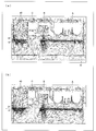
図15(a)および(b)は、液晶パネルの上面に偏光フィルムを貼合する場合の気流(ダウンフロー)のベクトル方向を示す図である。図15(a)および(b)における、領域Aは、偏光フィルムを巻出す巻出部等が設置される領域であり、領域Bは主に偏光フィルムが通過する領域であり、領域Cは、偏光フィルムから除去された保護フィルムを巻き取る巻取部等が設置される領域である。同図において、HEPA(High Efficiency Particulate Air)フィルター40からはクリーンエアーが供給される。なお、図15(a)では、クリーンエアーが通過可能なグレーチング41が設置されているためグレーチング41を介して気流が垂直方向に移動することが可能である。一方、図15(b)では、グレーチング41が設置されていないため、気流は図15(b)の最下部の床に接触した後、床に沿って移動することとなる。
FIGS. 15A and 15B are diagrams showing the vector direction of airflow (down flow) when a polarizing film is bonded to the upper surface of the liquid crystal panel. In FIGS. 15 (a) and 15 (b), region A is a region where an unwinding part and the like for unwinding the polarizing film are installed, region B is a region through which the polarizing film mainly passes, and region C is This is an area in which a winding unit and the like for winding the protective film removed from the polarizing film are installed. In the figure, clean air is supplied from an HEPA (High Efficiency Particulate Air) filter 40. In FIG. 15A, since the grating 41 through which clean air can pass is installed, the airflow can move in the vertical direction via the grating 41. On the other hand, in FIG. 15B, since the grating 41 is not installed, the airflow moves along the floor after contacting the bottom floor in FIG. 15B.
図15(a)および(b)には、領域A~Cが2F(2階)部分に配置されており、1Fと2Fの間には、液晶パネルを搬送する搬送機構が設置されている。HEPAフィルター40からのクリーンエアーは、領域A~Cによって妨げられるため、2F部分を通過する液晶パネルに対して垂直方向に向う気流が生じ難い。これに対して、水平方向の気流ベクトルは大きな(ベクトルの密度が濃い)状態となっている。すなわち、搬送機構によって搬送される液晶パネルの上側に向かう気流は生じ難くなっており、整流環境が悪化した状態であることが分かった。
15A and 15B, regions A to C are arranged on the 2F (second floor) portion, and a transport mechanism for transporting the liquid crystal panel is installed between 1F and 2F. Since the clean air from the HEPA filter 40 is blocked by the areas A to C, it is difficult to generate an airflow in the vertical direction with respect to the liquid crystal panel passing through the 2F portion. On the other hand, the airflow vector in the horizontal direction is large (vector density is high). That is, it was found that the air flow toward the upper side of the liquid crystal panel transported by the transport mechanism is less likely to occur, and the rectification environment has deteriorated.
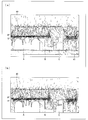
一方、液晶パネルの下面に偏光フィルムを貼合する場合の気流(ダウンフロー)のベクトル方向を図16(a)および(b)に示す。下貼り型の場合、HEPAフィルター40から供給されたクリーンエアーは、領域A~Cに妨げられることなく、1Fと2Fとの間の搬送機構に向かい、整流環境が妨げられていないことが分かる。なお、図16(a)では、クリーンエアーが通過可能なグレーチング41が設置されているため、グレーチング41を介して、気流が垂直方向に移動することが可能である。これらの知見から、本発明者らは液晶パネルに偏光フィルムを貼合する際、液晶パネルの貼合を、両面とも下方向から行うことを見出した。
On the other hand, the vector direction of the airflow (down flow) when a polarizing film is bonded to the lower surface of the liquid crystal panel is shown in FIGS. 16 (a) and 16 (b). In the case of the bottom paste type, it can be seen that the clean air supplied from the HEPA filter 40 goes to the transport mechanism between 1F and 2F without being blocked by the areas A to C, and the rectifying environment is not blocked. In FIG. 16A, since the grating 41 through which clean air can pass is installed, the airflow can move in the vertical direction via the grating 41. Based on these findings, the present inventors have found that when a polarizing film is bonded to a liquid crystal panel, the liquid crystal panel is bonded from both sides from below.
本発明者らは上記知見を考慮して、本発明を完成させた。すなわち、光学表示装置を製造する製造システムにおいて、液晶パネルを搬送する搬送機構と、液晶パネルの下面に偏光フィルムを貼合する2つの貼合機構とを備え、上記貼合機構は、保護フィルムによって表面が保護された偏光フィルムを巻出す第1巻出部と、第1巻出部から巻き出された偏光フィルムに連結される補充用の偏光フィルムを巻き出す第2巻出部と、上記偏光フィルムから保護フィルムを剥離する剥離部と、保護フィルムが剥離された偏光フィルムを液晶パネルの下面に貼合する貼合部と、上記偏光フィルムから剥離された保護フィルムを巻取る巻取部とを含み、上記搬送機構には、一方の貼合機構によって下面に偏光フィルムが貼合された液晶パネルを反転させる反転部が備えられており、上記第1巻出部および第2巻出部は、偏光フィルムの巻芯方向に沿って水平に移動可能であり、上記第1巻出部および第2巻出部は、互いに並設されている。
The inventors have completed the present invention in consideration of the above findings. That is, in a manufacturing system for manufacturing an optical display device, a transport mechanism for transporting a liquid crystal panel, and two bonding mechanisms for bonding a polarizing film to the lower surface of the liquid crystal panel, the bonding mechanism is a protective film. A first unwinding unit for unwinding the polarizing film whose surface is protected; a second unwinding unit for unwinding a polarizing film for replenishment connected to the polarizing film unwound from the first unwinding unit; The peeling part which peels a protective film from a film, the bonding part which bonds the polarizing film from which the protective film was peeled to the lower surface of a liquid crystal panel, and the winding part which winds up the protective film peeled from the said polarizing film In addition, the transport mechanism includes a reversing unit for reversing the liquid crystal panel having the polarizing film bonded to the lower surface by one bonding mechanism, and the first unwinding unit and the second unwinding unit. Are movable horizontally along the core direction of the polarizing film, the first unwinding unit and the second unwinding unit, are juxtaposed to each other.
当該製造システムでは、搬送機構によって搬送される液晶パネルに対して、一方の貼合機構によって液晶パネルの下面に偏光フィルムが貼合される。この液晶パネルは反転部によって反転され、他方の貼合機構によって液晶パネルの下面に偏光フィルムが貼合され、製造システムにおける整流環境を悪化させずに液晶フィルムの両面に液晶パネルが貼合された光学表示装置が製造される。
In the manufacturing system, a polarizing film is bonded to the lower surface of the liquid crystal panel by one bonding mechanism with respect to the liquid crystal panel conveyed by the conveyance mechanism. This liquid crystal panel was inverted by the reversing part, and the polarizing film was bonded to the lower surface of the liquid crystal panel by the other bonding mechanism, and the liquid crystal panel was bonded to both surfaces of the liquid crystal film without deteriorating the rectifying environment in the manufacturing system. An optical display device is manufactured.
また、上記製造システムの貼合機構には、第1巻出部および第2巻出部の2つの巻出部が備えられており、これらは併設されている。このため、第1巻出部の偏光フィルムの残量が尽きかけた場合、第1巻出部の偏光フィルムのロールを新たなロールに交換せずとも、第2巻出部の偏光フィルムを用いて、両巻出部の偏光フィルム同士を即座に連結させることができ、速やかに偏光フィルムを巻き出すことができる。したがって、原反ロールの交換作業に必要な時間を削減することができる為、光学表示装置の製造時間を短縮することが可能である。
In addition, the bonding mechanism of the manufacturing system is provided with two unwinding portions, a first unwinding portion and a second unwinding portion, which are provided side by side. For this reason, when the remaining amount of the polarizing film in the first unwinding portion is almost exhausted, the polarizing film in the second unwinding portion is used without replacing the polarizing film roll in the first unwinding portion with a new roll. Thus, the polarizing films of both unwinding portions can be immediately connected to each other, and the polarizing film can be unwound quickly. Therefore, since the time required for the replacement work of the original fabric roll can be reduced, the manufacturing time of the optical display device can be shortened.
また、両巻出部は、偏光フィルムの巻芯方向に沿って水平に移動可能であるため、偏光フィルムを交換する場合、上記水平方向に移動した巻出部に新たな偏光フィルムの原反ロールを設置することができる。したがって、従来のターレットを有するラミネート加工機とは異なり、巻出部は上方に向かって移動しない。このため、巻出部の移動する範囲を小さくすることができ、小型化された製造システムを提供することができる。
Moreover, since both unwinding parts can move horizontally along the winding core direction of the polarizing film, when replacing the polarizing film, a new original roll of polarizing film is added to the unwinding part moved in the horizontal direction. Can be installed. Therefore, unlike a laminating machine having a conventional turret, the unwinding portion does not move upward. For this reason, the range which an unwinding part moves can be made small, and the manufacturing system reduced in size can be provided.
本発明の光学表示装置の製造システムは、以上のように、液晶パネルを搬送する搬送機構と、液晶パネルの下面に偏光フィルムを貼合する2つの貼合機構とを備え、上記貼合機構は、保護フィルムによって表面が保護された偏光フィルムを巻出す第1巻出部と、第1巻出部から巻き出された偏光フィルムに連結される補充用の偏光フィルムを巻き出す第2巻出部と、上記偏光フィルムから保護フィルムを剥離する剥離部と、保護フィルムが剥離された偏光フィルムを液晶パネルの下面に貼合する貼合部と、上記偏光フィルムから剥離された保護フィルムを巻取る巻取部とを含み、上記搬送機構には、一方の貼合機構によって下面に偏光フィルムが貼合された液晶パネルを反転させる反転部が備えられており、上記第1巻出部および第2巻出部は、偏光フィルムの巻芯方向に沿って水平に移動可能であり、上記第1巻出部および第2巻出部は、互いに並設されているものである。
As described above, the optical display device manufacturing system of the present invention includes the transport mechanism for transporting the liquid crystal panel and the two bonding mechanisms for bonding the polarizing film to the lower surface of the liquid crystal panel. A first unwinding unit for unwinding the polarizing film whose surface is protected by the protective film, and a second unwinding unit for unwinding the supplementary polarizing film connected to the polarizing film unwound from the first unwinding unit. And a peeling part for peeling the protective film from the polarizing film, a bonding part for bonding the polarizing film from which the protective film was peeled to the lower surface of the liquid crystal panel, and a winding for winding the protective film peeled from the polarizing film. A reversing unit for reversing a liquid crystal panel having a polarizing film bonded to the lower surface by one bonding mechanism, and the first unwinding unit and the second winding. Out Are movable horizontally along the core direction of the polarizing film, the first unwinding unit and the second unwinding unit are those that are juxtaposed to each other.
それゆえ、上記製造システムの貼合機構には、第1巻出部および第2巻出部の2つの巻出部が備えられており、これらは併設されている。このため、第1巻出部の偏光フィルムの残量が尽きかけた場合、第1巻出部の偏光フィルムのロールを新たなロールに交換せずとも、第2巻出部の偏光フィルムを用いて、両巻出部の偏光フィルム同士を即座に連結させることができ、速やかに偏光フィルムを巻き出すことができる。したがって、原反ロールの交換作業に必要な時間を削減することができる為、光学表示装置の製造時間を短縮することが可能である。
Therefore, the bonding mechanism of the above manufacturing system is provided with two unwinding portions, a first unwinding portion and a second unwinding portion, which are provided side by side. For this reason, when the remaining amount of the polarizing film in the first unwinding portion is almost exhausted, the polarizing film in the second unwinding portion is used without replacing the polarizing film roll in the first unwinding portion with a new roll. Thus, the polarizing films of both unwinding portions can be immediately connected to each other, and the polarizing film can be unwound quickly. Therefore, since the time required for the replacement work of the original fabric roll can be reduced, the manufacturing time of the optical display device can be shortened.
また、上記の両巻出部は、偏光フィルムの巻芯方向に沿って水平に移動可能であるため、偏光フィルムを交換する場合、上記水平方向に移動した巻出部に新たな偏光フィルムの原反ロールを設置することができる。したがって、従来のターレットを有するラミネート加工機とは異なり、巻出部は上方に向かって移動しない。このため、巻出部の移動する範囲を小さくすることができ、小型化された製造システムを提供することができるという効果を奏する。
In addition, since both the unwinding portions can be moved horizontally along the winding core direction of the polarizing film, when replacing the polarizing film, a new polarizing film original is added to the unwinding portion moved in the horizontal direction. Anti-roll can be installed. Therefore, unlike a laminating machine having a conventional turret, the unwinding portion does not move upward. For this reason, it is possible to reduce the range in which the unwinding part moves and to provide an effect that a miniaturized manufacturing system can be provided.
本発明の一実施形態について図1ないし図14に基づいて説明すれば、以下の通りである。
An embodiment of the present invention will be described with reference to FIGS. 1 to 14 as follows.
〔光学表示装置の製造システムの構成〕
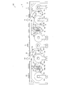
図1は、本発明に係る光学表示装置の製造システム100を示す側面図である。製造システム100は積層フィルム10を巻出し、積層フィルム10から保護フィルム10aを剥離し、偏光フィルム10bを液晶パネル2の片面に貼合するものである。その後、製造システム100は、液晶パネル2の逆面に偏光フィルム110bを貼合し、光学表示装置が製造される。液晶パネル2としては、公知の液晶パネルを用いればよく、ガラス基板などの基板と液晶層との間に配向膜を配した公知の液晶パネルが挙げられる。 [Configuration of optical display device manufacturing system]
FIG. 1 is a side view showing an optical displaydevice manufacturing system 100 according to the present invention. The manufacturing system 100 unwinds the laminated film 10, peels the protective film 10 a from the laminated film 10, and bonds the polarizing film 10 b to one side of the liquid crystal panel 2. Thereafter, the manufacturing system 100 bonds the polarizing film 110b to the opposite surface of the liquid crystal panel 2, and the optical display device is manufactured. As the liquid crystal panel 2, a known liquid crystal panel may be used, and a known liquid crystal panel in which an alignment film is disposed between a substrate such as a glass substrate and a liquid crystal layer may be used.
図1は、本発明に係る光学表示装置の製造システム100を示す側面図である。製造システム100は積層フィルム10を巻出し、積層フィルム10から保護フィルム10aを剥離し、偏光フィルム10bを液晶パネル2の片面に貼合するものである。その後、製造システム100は、液晶パネル2の逆面に偏光フィルム110bを貼合し、光学表示装置が製造される。液晶パネル2としては、公知の液晶パネルを用いればよく、ガラス基板などの基板と液晶層との間に配向膜を配した公知の液晶パネルが挙げられる。 [Configuration of optical display device manufacturing system]
FIG. 1 is a side view showing an optical display
製造システム100は、大きく分類して搬送機構12と2つの貼合機構とを備えている。第1の貼合機構の各部材としては、巻出部(第1巻出部)1、巻出部(第2巻出部)1a、フィルム連結部(第1フィルム連結部)3、フィルム連結部(第2フィルム連結部)13、ガイドローラ16、ハーフカッター21、支持台22、ナイフエッジ(剥離部)23、ニップローラ24・24a、巻取部25が備えられている(製造システムの100の右側)。なお、本明細書において「・」は「および」を意味する。
The manufacturing system 100 is roughly classified and includes a transport mechanism 12 and two bonding mechanisms. As each member of the 1st pasting mechanism, unwinding part (1st unwinding part) 1, unwinding part (2nd unwinding part) 1a, film connection part (1st film connection part) 3, film connection Part (second film connecting part) 13, guide roller 16, half cutter 21, support base 22, knife edge (peeling part) 23, nip rollers 24 and 24 a, and take-up part 25 (100 of the manufacturing system). Right). In the present specification, “•” means “and”.
さらに、第2の貼合機構が製造システム100の左側に備えられている。製造システム100には、巻出部(第1巻出部)101、巻出部(第2巻出部)101a、フィルム連結部(第1フィルム連結部)103、フィルム連結部(第2フィルム連結部)113、ガイドローラ116、ハーフカッター121、支持台122、ナイフエッジ123、ニップローラ124・124a、巻取部125が備えられている。
Furthermore, a second bonding mechanism is provided on the left side of the manufacturing system 100. The manufacturing system 100 includes an unwinding part (first unwinding part) 101, an unwinding part (second unwinding part) 101a, a film connecting part (first film connecting part) 103, and a film connecting part (second film connecting part). Part) 113, a guide roller 116, a half cutter 121, a support stand 122, a knife edge 123, nip rollers 124 and 124a, and a winding part 125.
図1のように、第1の貼合機構および第2の貼合機構は、搬送機構12の下方に設置されている。第1の貼合機構はニップローラ24・24aは、液晶パネル2の搬送経路の上流側、第2の貼合機構は、ニップローラ124・124aが液晶パネル2の搬送経路の下流側に位置するように配置されている。
As shown in FIG. 1, the first bonding mechanism and the second bonding mechanism are installed below the transport mechanism 12. The first bonding mechanism is such that the nip rollers 24 and 24a are positioned upstream of the transport path of the liquid crystal panel 2, and the second bonding mechanism is such that the nip rollers 124 and 124a are positioned downstream of the transport path of the liquid crystal panel 2. Has been placed.
両貼合機構のうち、ニップローラ24・124は、液晶パネル2の上面付近、ニップローラ24a・124aは、液晶パネルの下面の可能な高さに備えられている。一方、両貼合機構におけるこれらニップローラ以外の各部材は、搬送機構12の下方に備えられている。また、搬送機構12には、反転部26が備えられている。以下、各部材について説明する。
Among the pasting mechanisms, the nip rollers 24 and 124 are provided near the upper surface of the liquid crystal panel 2, and the nip rollers 24a and 124a are provided at a possible height on the lower surface of the liquid crystal panel. On the other hand, each member other than the nip rollers in both the bonding mechanisms is provided below the transport mechanism 12. Further, the transport mechanism 12 includes a reversing unit 26. Hereinafter, each member will be described.
巻出部1および巻出部1aは、保護フィルム10a・20aが粘着層を介して偏光フィルム10b・20bを保護している積層フィルム10・20の原反ロールを保持し、巻き出す装置であり、積層フィルム10・20へ加えられる張力を調整可能である。巻出部1から巻き出された積層フィルム10は、各ガイドローラ16を介してライン側に送られる。ラインとは、積層フィルム10が搬送される経路のことをいい、ライン方向とは積層フィルム10が搬送される方向のことをいう。一方、巻出部側とはライン側と反対方向のことをいう。巻出部1aから巻き出される積層フィルム20のラインについても同様である。
The unwinding part 1 and the unwinding part 1a are apparatuses for holding and unwinding the raw roll of the laminated films 10 and 20 in which the protective films 10a and 20a protect the polarizing films 10b and 20b through the adhesive layer. The tension applied to the laminated films 10 and 20 can be adjusted. The laminated film 10 unwound from the unwinding unit 1 is sent to the line side via each guide roller 16. The line refers to the path through which the laminated film 10 is conveyed, and the line direction refers to the direction in which the laminated film 10 is conveyed. On the other hand, the unwinding part side means the direction opposite to the line side. The same applies to the line of the laminated film 20 that is unwound from the unwinding portion 1a.
巻出部1aには原反ロールR1aが設置されており、この原反ロールR1aは補充用である。巻出部1の原反ロールR1の残量が尽きかけた際に、原反ロールR1aが巻き出され、積層フィルム10・20が連結される。なお、巻出部1・1aの詳細については図4を用いて後述する。
A raw roll R1a is installed in the unwinding portion 1a, and this raw roll R1a is used for replenishment. When the remaining amount of the raw roll R1 in the unwinding unit 1 is almost exhausted, the raw roll R1a is unwound and the laminated films 10 and 20 are connected. Details of the unwinding portions 1 and 1a will be described later with reference to FIG.
以下、主に第1の貼合機構の部材について説明するが、特に断りのない限り、第2の貼合機構における同一名称の部材についても同様である。
Hereinafter, although the member of a 1st bonding mechanism is mainly demonstrated, it is the same also about the member of the same name in a 2nd bonding mechanism unless there is particular notice.
積層フィルム10は、液晶パネル2と貼合される偏光フィルム10bに粘着層を介して保護フィルム10aが積層されたフィルムであり、ガイドローラ16を介して送り出される。積層フィルム10は、保護フィルムによって表面が保護された偏光フィルムであるともいえる。本実施の形態において、積層フィルム10を巻き出す速度、張力等は適宜調整すればよい。巻出部1、1a、101、101aの幅は、使用する積層フィルム10の幅によって適宜変更すればよく、特に限定されるものではない。例えば、フィルム幅が300mm以上、1200mm以下の積層フィルム10を設置可能な幅の巻出部を使用すればよい。
The laminated film 10 is a film in which a protective film 10a is laminated on a polarizing film 10b bonded to the liquid crystal panel 2 via an adhesive layer, and is sent out via a guide roller 16. It can be said that the laminated film 10 is a polarizing film whose surface is protected by a protective film. In this Embodiment, what is necessary is just to adjust the speed | rate, tension | tensile_strength, etc. which unwind the laminated | multilayer film 10 suitably. What is necessary is just to change suitably the width | variety of the unwinding part 1, 1a, 101, 101a with the width | variety of the laminated | multilayer film 10 to be used, and it is not specifically limited. For example, an unwinding portion having a width capable of installing the laminated film 10 having a film width of 300 mm or more and 1200 mm or less may be used.
積層フィルム10は3層構造になっており、公知の構造を採用でき、保護フィルム10a、図示しない粘着層および偏光フィルム10bから構成されている。偏光フィルム10bの構成の一例として、偏光子フィルムの両面に保護フィルムとしてTAC(トリアセチルセルロース)フィルム等が貼合されており、一方または両方のTACフィルムに粘着層が塗布(積層)されており、粘着層に保護フィルム10aが積層された構成が挙げられる。
The laminated film 10 has a three-layer structure, and can adopt a known structure, and includes a protective film 10a, an adhesive layer (not shown), and a polarizing film 10b. As an example of the configuration of the polarizing film 10b, a TAC (triacetylcellulose) film or the like is bonded as a protective film on both sides of the polarizer film, and an adhesive layer is applied (laminated) to one or both TAC films. The structure by which the protective film 10a was laminated | stacked on the adhesion layer is mentioned.
上記偏光子フィルムとしては、ポリビニルアルコールフィルムがヨウ素等によって染色されており、1軸方向に延伸されたフィルムを用いることができる。また、上記フィルムに代えて、部分ホルマール化ポリビニルアルコール系フィルム、エチレン・酢酸ビニル共重合体系部分ケン化フィルム、セルロース系フィルム等の親水性高分子フィルム等、ポリビニルアルコールの脱水処理物やポリ塩化ビニルの脱塩酸処理物等のポリエン配向フィルム等を使用することもできる。
As the polarizer film, a polyvinyl alcohol film dyed with iodine or the like and a film stretched in a uniaxial direction can be used. Also, in place of the above films, partially formalized polyvinyl alcohol film, ethylene / vinyl acetate copolymer partially saponified film, hydrophilic polymer film such as cellulose film, etc., dehydrated polyvinyl alcohol and polyvinyl chloride A polyene-oriented film such as a dehydrochlorinated product can also be used.
また、偏光フィルム10bの幅は、300mm以上、1200mm以下とすることができる。製造システム100では、まず、液晶パネル2の搬送方向D1に液晶パネル2の短辺が沿った状態で偏光フィルム10bが貼合され、次に、液晶パネル2の搬送方向D1に液晶パネル2の長辺が沿った状態で偏光フィルム10bが貼合される。このため、偏光フィルム10bの幅は液晶パネル2の長辺に対応した長さであり、偏光フィルム110bの幅は液晶パネル2の短辺に対応した長さである。
Moreover, the width of the polarizing film 10b can be 300 mm or more and 1200 mm or less. In the manufacturing system 100, first, the polarizing film 10b is bonded with the short side of the liquid crystal panel 2 along the transport direction D1 of the liquid crystal panel 2, and then the length of the liquid crystal panel 2 in the transport direction D1 of the liquid crystal panel 2. The polarizing film 10b is bonded in a state where the sides are aligned. Therefore, the width of the polarizing film 10 b is a length corresponding to the long side of the liquid crystal panel 2, and the width of the polarizing film 110 b is a length corresponding to the short side of the liquid crystal panel 2.
保護フィルム10a、粘着層および偏光フィルム10bの総厚さは、特に限定されないが、一例として、100μm以上、500μm以下とすることができる。なお、偏光フィルム10b・110bのうち偏光子フィルムの厚さは、概して10μm以上、50μm以下である。さらに、積層フィルム10の実用上、問題ない範囲にて上記3層以外にさらに他の層を含んでいてもよい。
The total thickness of the protective film 10a, the pressure-sensitive adhesive layer, and the polarizing film 10b is not particularly limited, but can be 100 μm or more and 500 μm or less as an example. In addition, generally the thickness of a polarizer film is 10 micrometers or more and 50 micrometers or less among polarizing films 10b * 110b. Furthermore, in addition to the above three layers, other layers may be included within the practical range of the laminated film 10.
粘着層は、保護フィルム10aが除去された後に、偏光フィルム10bと液晶パネル2とを貼合するために用いられる。粘着層に用いられる粘着剤としては、特に限定されるものではなく、アクリル系、エポキシ系、ポリウレタン系などの粘着剤を用いることができるが、保護フィルム10aから剥離し易い必要がある。このため、保護フィルム10aに応じて粘着剤の種類が選択される。なお、粘着層の厚さは適宜変更すればよく、例えば、0.5μm以上、75μm以下とすることができる。
The adhesive layer is used to bond the polarizing film 10b and the liquid crystal panel 2 after the protective film 10a is removed. The pressure-sensitive adhesive used for the pressure-sensitive adhesive layer is not particularly limited, and an acrylic, epoxy, polyurethane-based pressure-sensitive adhesive can be used, but it needs to be easily peeled off from the protective film 10a. For this reason, the kind of adhesive is selected according to the protective film 10a. In addition, what is necessary is just to change the thickness of the adhesion layer suitably, for example, can be 0.5 micrometer or more and 75 micrometers or less.
保護フィルム10aとしては公知の保護フィルムを用いればよい。具体的には、ポリエステルフィルム、ポリエチレンテレフタラートフィルムなどを用いることができる。上記保護フィルムの厚さとしては、特に限定されないが、5μm以上、100μm以下の保護フィルムを好ましく用いることができる。保護フィルム10aの幅は、偏光フィルム10bと同様に、300mm以上、1200mm以下とすることができる。なお、保護フィルム10aは、一般的に剥離フィルム、セパレータなどと称されることもある。
A known protective film may be used as the protective film 10a. Specifically, a polyester film, a polyethylene terephthalate film, or the like can be used. Although it does not specifically limit as thickness of the said protective film, The protective film of 5 micrometers or more and 100 micrometers or less can be used preferably. The width | variety of the protective film 10a can be 300 mm or more and 1200 mm or less similarly to the polarizing film 10b. In addition, the protective film 10a may be generally called a peeling film or a separator.
搬送機構12は液晶パネル2を運搬するものであり、液晶パネル2と偏光フィルム10b(または20b)との貼合を行うニップローラ(貼合部)24・24a、反転部26およびニップローラ124・124aに液晶パネル2を運搬する。ニップローラ24a・124aは、搬送機構12と並ぶように同じ高さに配置されている。
The transport mechanism 12 transports the liquid crystal panel 2, and is attached to the nip rollers (bonding portions) 24 and 24 a for bonding the liquid crystal panel 2 and the polarizing film 10 b (or 20 b), the reversing portion 26, and the nip rollers 124 and 124 a. Transport the liquid crystal panel 2. The nip rollers 24 a and 124 a are arranged at the same height so as to be aligned with the transport mechanism 12.
搬送機構12は、ローラ構造となっているが、搬送機構12としては液晶パネルを運搬することができればよく、ローラー構造に限定されるものではない。搬送機構12によって液晶パネル2が図中、右側から左側(ニップローラ24・24a側)へと搬送される。なお、フィルム連結部3・13(フィルム連結部103・113)、および、図1では図示しない切断機については後述する。
The transport mechanism 12 has a roller structure, but the transport mechanism 12 is not limited to the roller structure as long as the liquid crystal panel can be transported. The liquid crystal panel 2 is transported by the transport mechanism 12 from the right side to the left side (nip rollers 24 and 24a side) in the drawing. The film connecting parts 3 and 13 (film connecting parts 103 and 113) and a cutting machine not shown in FIG. 1 will be described later.
積層フィルム10は各ガイドローラ16を介して搬送されるが、液晶パネル2は枚葉状であるため、偏光フィルム10bの貼合前に長尺の偏光フィルム10bおよび粘着層を切断する必要がある。すなわち、積層フィルム10をハーフカットする必要がある。ハーフカットを行うための部材が、ハーフカッター21および支持台22である。支持台22は、保護フィルム10aに接触する位置に配置されており、積層フィルム10にぶれを生じ難くするために設置されている。また、ハーフカッター21は、粘着層および保護フィルム10aを切断する位置に設置されており、保護フィルム10a側が支持台22に支持された状態にて、偏光フィルム10bおよび接着層がハーフカッター21によって切断される。このとき保護フィルム10aは切断されない。すなわち、積層フィルム10がハーフカットされる。
The laminated film 10 is conveyed through each guide roller 16, but since the liquid crystal panel 2 has a single sheet shape, it is necessary to cut the long polarizing film 10b and the adhesive layer before the polarizing film 10b is bonded. That is, it is necessary to half-cut the laminated film 10. The members for performing the half cut are the half cutter 21 and the support base 22. The support base 22 is disposed at a position in contact with the protective film 10 a and is installed to make it difficult for the laminated film 10 to be shaken. Moreover, the half cutter 21 is installed in the position which cut | disconnects the adhesion layer and the protective film 10a, and the polarizing film 10b and an adhesive layer are cut | disconnected by the half cutter 21 in the state in which the protective film 10a side was supported by the support stand 22. Is done. At this time, the protective film 10a is not cut. That is, the laminated film 10 is half cut.
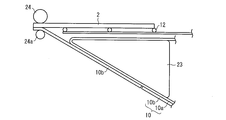
次に、図2を用いて偏光フィルム10bと液晶パネル2との貼合について説明する。図2は、ニップローラ24・24a付近の構造を示す側面図である。図2に示すように、積層フィルム10はハーフカッター21によってハーフカットされており、偏光フィルム10bは図示しない粘着層を介して保護フィルムに付着している。すなわち、偏光フィルム10bはニップローラ24・24aに到達する前に、ハーフカッター21によって、液晶パネル2との貼合に好ましいサイズにカットされている。一方、保護フィルム10aはカットされていない。
Next, the bonding between the polarizing film 10b and the liquid crystal panel 2 will be described with reference to FIG. FIG. 2 is a side view showing a structure in the vicinity of the nip rollers 24 and 24a. As shown in FIG. 2, the laminated film 10 is half-cut by a half cutter 21, and the polarizing film 10 b is attached to the protective film via an adhesive layer (not shown). That is, before reaching the nip rollers 24 and 24a, the polarizing film 10b is cut by the half cutter 21 to a size preferable for bonding with the liquid crystal panel 2. On the other hand, the protective film 10a is not cut.
この保護フィルム10aはナイフエッジ23によって剥離される。ナイフエッジ23は、その側面の形状として略三角形形状を有しており、側面形状は角がなく滑らかである。ナイフエッジ23の底面(押圧面)は傾斜が設けられており、保護フィルム10aの搬送方向に沿って配置されている。ナイフエッジ23は、保護フィルム10aとの摩擦力が小さく、保護フィルム10aが粘着層から容易に剥離することができる部材、例えばダイヤモンドライクカーボン等で表面加工されている。これにより、保護フィルム10aはナイフエッジ23に追随して移動し、ナイフエッジ23の先端部にて積層フィルム10から剥離し、除去され、その後、巻取部25に巻き取られる。ナイフエッジ23を構成する材料としては、金属材料、樹脂材料等が適用可能であり、特に制限されないが、ステンレス、アルミニウム、樹脂材料などが耐蝕性の点から推奨され、具体的にはSUS304、SUS420などが挙げられる。
The protective film 10a is peeled off by the knife edge 23. The knife edge 23 has a substantially triangular shape as a side surface thereof, and the side surface shape is smooth with no corners. The bottom surface (pressing surface) of the knife edge 23 is provided with an inclination and is disposed along the conveying direction of the protective film 10a. The knife edge 23 has a small frictional force with the protective film 10a, and is surface-treated with a member that allows the protective film 10a to be easily peeled off from the adhesive layer, such as diamond-like carbon. As a result, the protective film 10 a moves following the knife edge 23, is peeled off from the laminated film 10 at the tip of the knife edge 23, is removed, and is then wound around the winding unit 25. As a material constituting the knife edge 23, a metal material, a resin material, or the like can be applied, and is not particularly limited. However, stainless steel, aluminum, a resin material, and the like are recommended in terms of corrosion resistance, and specifically, SUS304, SUS420. Etc.
巻取部25は、保護フィルム10aを巻取る装置であり、巻取りの用途に使用される以外の基本的な構造は巻出部1・1aと同様である。なお、巻出部1・1aと同様に、2つの巻取部が備えられた構造であってもよい。
The winding unit 25 is a device that winds the protective film 10a, and has the same basic structure as that of the unwinding unit 1 and 1a except that it is used for winding. In addition, the structure provided with the two winding parts similarly to the unwinding part 1 * 1a may be sufficient.
ニップローラ24・24aは、搬送機構12によって搬送された液晶パネル2と、偏光フィルム10b(または20b)とを圧着して貼合するものである。ニップローラ24・24aによる貼合時の圧力は適宜調整可能である。
The nip rollers 24 and 24a are for bonding the liquid crystal panel 2 transported by the transport mechanism 12 and the polarizing film 10b (or 20b) by pressure bonding. The pressure at the time of bonding by the nip rollers 24 and 24a can be adjusted as appropriate.
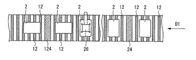
下面に偏光フィルム10bが貼合された液晶パネル2は、搬送機構12によって反転部26へ搬送される。反転部26は、液晶パネルを反転させる部材であり、ロボットアーム等の公知の構造によって設計すればよい。図3は、製造システム100を搬送機構12に向かって示す平面図である。
The liquid crystal panel 2 having the polarizing film 10b bonded to the lower surface is transported to the reversing unit 26 by the transport mechanism 12. The reversing unit 26 is a member that reverses the liquid crystal panel, and may be designed with a known structure such as a robot arm. FIG. 3 is a plan view showing the manufacturing system 100 toward the transport mechanism 12.
同図に示すように、本実施の形態に係る製造システム100では、好ましい形態として液晶パネルの搬送方向が直線状であり、L字方向などの直角に曲がるような搬送方向の製造システムとは異なる。この直線状の構造であれば、搬送機構12を直線状に配置でき、搬送機構12の下方に配置される第1の貼合機構および第2の貼合機構を配置できる。このため、製造システム100の構造を直線に沿った構造に設計することができ、面積効率に優れた製造システムを提供できる。光学表示装置はクリーンルームで製造されることが通常であり、クリーンルームの製造コストは高いため、面積効率に優れる本製造システム100は有益である。
As shown in the figure, in the manufacturing system 100 according to the present embodiment, as a preferable mode, the liquid crystal panel is transported in a straight line direction, which is different from the manufacturing system in the transport direction that bends at right angles such as the L-shaped direction. . If it is this linear structure, the conveyance mechanism 12 can be arrange | positioned linearly and the 1st bonding mechanism and 2nd bonding mechanism which are arrange | positioned under the conveyance mechanism 12 can be arrange | positioned. For this reason, the structure of the manufacturing system 100 can be designed into a structure along a straight line, and the manufacturing system excellent in area efficiency can be provided. Since the optical display device is normally manufactured in a clean room, and the manufacturing cost of the clean room is high, the manufacturing system 100 having excellent area efficiency is useful.
反転部26には吸着部が備えられており、図3では、反転部26の吸着部によって液晶パネル2の上面が吸着された状態が示されている。上記吸着部は、液晶パネル2を吸着および脱着可能であればよく、反転部26では、空気吸引式の吸着部を使用している。液晶パネル2の吸着後、反転部26のロボットアームによって液晶パネル2が反転される。反転された液晶パネル2では、片面に貼合された偏光フィルム10bが液晶パネル2の上面に位置している。
The reversing part 26 is provided with a suction part. FIG. 3 shows a state in which the upper surface of the liquid crystal panel 2 is sucked by the suction part of the reversing part 26. The adsorbing unit only needs to be able to adsorb and desorb the liquid crystal panel 2, and the reversing unit 26 uses an air suction type adsorbing unit. After the liquid crystal panel 2 is attracted, the liquid crystal panel 2 is reversed by the robot arm of the reversing unit 26. In the inverted liquid crystal panel 2, the polarizing film 10 b bonded to one side is located on the upper surface of the liquid crystal panel 2.
反転部26は、液晶パネル2を反転させると共に、液晶パネル2の搬送方向に沿った向きも変更する。製造システム100では、液晶パネル2は長方形であり、まず短辺が搬送方向に沿って搬送され、液晶パネル2の下面に偏光フィルム10bが貼合される。その後、反転部26によって、液晶パネル2の長辺が搬送方向に沿うように液晶パネル2の反転がなされる。これは、製造システム100で使用する偏光フィルムはフィルムの搬送方向に吸収軸が配置しているため、液晶パネル2の両面に貼合された偏光フィルムの吸収軸を互いに直交させるためである。
The reversing unit 26 reverses the liquid crystal panel 2 and also changes the direction along the transport direction of the liquid crystal panel 2. In the manufacturing system 100, the liquid crystal panel 2 is rectangular, and first, the short side is transported along the transport direction, and the polarizing film 10 b is bonded to the lower surface of the liquid crystal panel 2. Thereafter, the liquid crystal panel 2 is reversed by the reversing unit 26 so that the long side of the liquid crystal panel 2 is along the transport direction. This is because the polarizing film used in the manufacturing system 100 has the absorption axis arranged in the film transport direction, and thus the absorption axes of the polarizing film bonded to both surfaces of the liquid crystal panel 2 are orthogonal to each other.
反転され、長辺が搬送方向に沿った液晶パネル2に対して、第1の貼合機構と同様に、第2の貼合機構では巻出部101から巻き出された積層フィルム110から保護フィルム110aが剥離される。その後、ニップローラ124・124aによって、粘着層を介して偏光フィルム110bが液晶パネル2の下面に貼合される。こうして、液晶パネル2の両面に対して偏光フィルムが貼合された光学表示装置が製造される。液晶パネル2の両面に対して2枚の偏光フィルムが共に下面から貼合されるため、製造システム100周辺の整流環境は妨げられない。
For the liquid crystal panel 2 that is inverted and whose long side is along the transport direction, the protective film is formed from the laminated film 110 that is unwound from the unwinding portion 101 in the second bonding mechanism, similarly to the first bonding mechanism. 110a is peeled off. Thereafter, the polarizing film 110b is bonded to the lower surface of the liquid crystal panel 2 through the adhesive layer by the nip rollers 124 and 124a. Thus, an optical display device in which the polarizing film is bonded to both surfaces of the liquid crystal panel 2 is manufactured. Since two polarizing films are bonded together from the lower surface to both surfaces of the liquid crystal panel 2, the rectifying environment around the manufacturing system 100 is not hindered.
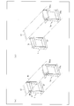
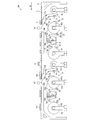
図4(a)は、製造システム100において巻出部1・1aが設置された状態を示す斜視図である。説明の便宜のため、フィルム連結部3などの他の部材は図示していない。本発明における巻出部1・1aについて説明するが、巻出部101・101aについても同様である。
FIG. 4A is a perspective view showing a state in which the unwinding portions 1 and 1a are installed in the manufacturing system 100. FIG. For convenience of explanation, other members such as the film connecting portion 3 are not shown. Although the unwinding part 1 * 1a in this invention is demonstrated, it is the same also about the unwinding part 101 * 101a.
本発明に係る巻出部1および巻出部1aは、偏光フィルム10bの巻芯方向に沿って水平に移動可能である。偏光フィルムの巻芯方向とは、巻出部1では原反ロールR1の巻芯方向であり、巻出部1aでは原反ロールR1aの巻芯方向であり、共に巻芯方向D2で示されている。図4(a)では、原反ロールR1の残量が低下した状態となっている。
The unwinding part 1 and the unwinding part 1a according to the present invention can move horizontally along the winding core direction of the polarizing film 10b. The core direction of the polarizing film is the core direction of the original roll R1 in the unwinding section 1, and the core direction of the original roll R1a in the unwinding section 1a, both of which are indicated by the core direction D2. Yes. In FIG. 4A, the remaining amount of the raw roll R1 is in a reduced state.
図4(b)は、巻出部1を巻芯方向D2に沿って水平に移動させた状態を示す斜視図である。巻出部1の底部に備えれたスライド式の移動機構27によって、巻出部1は移動する。図4(b)において、巻出部1は巻芯方向D2にのみ移動しているため、図4(b)の状態は、巻出部が巻芯方向D2に沿って移動された状態と換言できる。また、巻出部1は、巻芯方向D2に対して逆方向の偏光フィルムの巻芯方向に移動することももちろん可能である。なお、移動機構27によって、巻出部1は、巻出部1aに向かってまたは巻出部1aから遠ざかるように移動可能である。巻出部1aも移動機構27aを底部に備えており、巻出部1と同様に移動可能である。
FIG. 4B is a perspective view showing a state in which the unwinding portion 1 is moved horizontally along the core direction D2. The unwinding unit 1 is moved by a slide type moving mechanism 27 provided at the bottom of the unwinding unit 1. In FIG. 4B, since the unwinding part 1 has moved only in the core direction D2, the state of FIG. 4B is in other words a state in which the unwinding part has been moved along the core direction D2. it can. Of course, the unwinding part 1 can also move in the core direction of the polarizing film in the opposite direction to the core direction D2. The unwinding unit 1 can be moved by the moving mechanism 27 toward the unwinding unit 1a or away from the unwinding unit 1a. The unwinding part 1a also includes a moving mechanism 27a at the bottom, and can move similarly to the unwinding part 1.
巻出部1は巻芯方向D2に沿って移動可能であり、ターレットを有するラミネート加工機などとは異なり、巻出部1は上方に向かって移動しない。このため、巻出部1と搬送機構12との間に巻出部1が移動する空間を確保する必要がなく、巻出部1の移動する範囲を小さくすることができる。巻出部1aも同様である。このため、小型化された製造システム100を提供することができる。
The unwinding part 1 is movable along the core direction D2, and unlike a laminating machine having a turret, the unwinding part 1 does not move upward. For this reason, it is not necessary to secure a space in which the unwinding unit 1 moves between the unwinding unit 1 and the transport mechanism 12, and the range in which the unwinding unit 1 moves can be reduced. The same applies to the unwinding portion 1a. For this reason, the manufacturing system 100 reduced in size can be provided.
さらに、製造システム100は巻出部1・1aを併設して備えており、原反ロールR1の残量が尽きかけた場合、原反ロールR1から巻き出された積層フィルム10と原反ロールR1aから巻き出された積層フィルム20との連結を容易に行うことができる。この連結により、偏光フィルム10bと偏光フィルム20bとが連結される。なお、この連結は、オペレーターにより行うことができ、後述するように、フィルム連結部3・13を用いて行うこともできる。なお、巻出部1・1aは、それぞれに設置される原反ロールの巻芯の方向が搬送機構12による液晶パネル2の搬送方向と直交するように上記搬送方向に沿って並んで配置されている。
Furthermore, the manufacturing system 100 includes the unwinding portions 1 and 1a, and when the remaining amount of the original roll R1 is almost exhausted, the laminated film 10 and the original roll R1a unwound from the original roll R1. Can be easily connected to the laminated film 20 unwound from the wire. By this connection, the polarizing film 10b and the polarizing film 20b are connected. In addition, this connection can be performed by an operator, and can also be performed using the film connecting portions 3 and 13 as described later. The unwinding sections 1 and 1a are arranged side by side along the transport direction so that the direction of the core of the original roll installed in each is orthogonal to the transport direction of the liquid crystal panel 2 by the transport mechanism 12. Yes.
巻出部1・1aにおける原反ロールの交換を速やかに行う観点から、巻出部1と巻出部1aとの距離は、0.5m以上、5m以下であることが好ましい。さらに好ましくは、1m以上、3m以下である。巻出部1と巻出部1aとの距離とは、巻出部1・1aのうち、原反ロールR1・R1aの巻芯が設置される箇所同士を繋いだ距離をいう。
The distance between the unwinding portion 1 and the unwinding portion 1a is preferably 0.5 m or more and 5 m or less from the viewpoint of promptly replacing the raw roll in the unwinding portions 1 and 1a. More preferably, it is 1 m or more and 3 m or less. The distance between the unwinding part 1 and the unwinding part 1a refers to the distance between the unwinding parts 1 and 1a that connect the locations where the cores of the raw rolls R1 and R1a are installed.
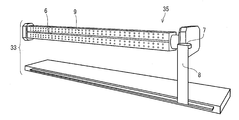
図5は、フィルム連結部3および切断機7を示す斜視図である。フィルム連結部3は、吸着部4・4aおよび切断貼合部5を備えている。
FIG. 5 is a perspective view showing the film connecting portion 3 and the cutting machine 7. The film connecting part 3 includes adsorption parts 4 and 4a and a cutting and bonding part 5.
吸着部4・4aは、偏光フィルムを吸着して保持するための部材である。吸着部4・4aは、平板形状を有しており、その表面に複数の吸着機構9を備えている。吸着機構9は偏光フィルムを吸着することができれば特に限定されるものではなく、ポンプによって空気を吸引して偏光フィルムを吸着する構成を採用することができる。
The adsorption parts 4 and 4a are members for adsorbing and holding the polarizing film. The adsorbing parts 4 and 4a have a flat plate shape and are provided with a plurality of adsorbing mechanisms 9 on the surface thereof. The adsorption mechanism 9 is not particularly limited as long as the polarizing film can be adsorbed, and a configuration in which the polarizing film is adsorbed by sucking air with a pump can be adopted.
切断貼合部5は回転可能であり、複数面を有する。具体的には、切断貼合部5は多角形形状を有しており、回転可能である。さらに、好ましい形態として、積層フィルム10(偏光フィルム10b)に対して垂直方向に移動可能となっている。積層フィルム10(偏光フィルム10b)に対して垂直方向に移動可能であることによって、切断貼合部5が回転する際、切断貼合部5は積層フィルム10(偏光フィルム10b)に対して垂直方向であって、偏光フィルム10bから遠ざかる方向に移動でき、移動後、回転することができる。さらにその後、切断貼合部5は偏光フィルム10bに対して垂直方向であって、偏光フィルム10bに近接する方向に移動して元の位置に戻ることができる。これにより、切断貼合部5の角部が偏光フィルム10bに接触することを確実に回避することが可能であり、非常に好ましい。
The cutting and bonding unit 5 is rotatable and has a plurality of surfaces. Specifically, the cutting and bonding unit 5 has a polygonal shape and is rotatable. Furthermore, as a preferable form, it is movable in the vertical direction with respect to the laminated film 10 (polarizing film 10b). By being movable in the vertical direction with respect to the laminated film 10 (polarizing film 10b), when the cutting and bonding part 5 rotates, the cutting and bonding part 5 is perpendicular to the laminated film 10 (polarizing film 10b). And it can move to the direction away from the polarizing film 10b, and can rotate after a movement. Furthermore, after that, the cutting and bonding part 5 can move in a direction perpendicular to the polarizing film 10b and close to the polarizing film 10b to return to the original position. Thereby, it is possible to avoid reliably that the corner | angular part of the cutting bonding part 5 contacts the polarizing film 10b, and it is very preferable.
なお、切断貼合部5は多角柱形状であり、図6にも示すように、その3面に切断支持面5a、貼合面5b・5cを備えているが、切断支持面および/または貼合面をさらに備えていてもよい。例えば、切断支持面を1面に、貼合面を3面または4面に備えている構成を挙げることができ、また、切断支持面を2面に、貼合面を3面または4面に備えている構成を挙げることもできる。図3の切断貼合部5のように、角部が面取りされていれば、偏光フィルムとの接触を回避できる観点から好ましい。切断貼合部5の大きさは、偏光フィルム10bの幅によって適宜決定すればよく、特に限定されるものではない。例えば、200mm以上、2000mm以下の長さ(偏光フィルム10bの幅方向の長さ)、10mm以上、300mm以下の幅(偏光フィルム10bの搬送方向の長さ)とすることができる。
In addition, the cutting bonding part 5 is a polygonal column shape, and as shown also in FIG. 6, although the cutting support surface 5a and the bonding surfaces 5b and 5c are provided in the three surfaces, a cutting support surface and / or a bonding are provided. A mating surface may be further provided. For example, the structure which is equipped with the cutting support surface on one surface and the bonding surface on three or four surfaces can be given, the cutting support surface is on two surfaces, and the bonding surface is on three or four surfaces. A configuration provided may also be mentioned. If the corner | angular part is chamfered like the cutting | lamination bonding part 5 of FIG. 3, it is preferable from a viewpoint which can avoid a contact with a polarizing film. What is necessary is just to determine suitably the magnitude | size of the cutting bonding part 5 with the width | variety of the polarizing film 10b, and it is not specifically limited. For example, the length (length in the width direction of the polarizing film 10b) of 200 mm or more and 2000 mm or less can be set to a width of 10 mm or more and 300 mm or less (length in the conveyance direction of the polarizing film 10b).
図6は切断貼合部5を示す斜視図である。図6は、図5の切断貼合部5を時計回りに1/3周回転させた状態を示している。図6に示すように、切断貼合部5は、切断支持面5aと、2以上の切断支持面5a・貼合面5bとを有している。切断支持面5aは、偏光フィルム10b(積層フィルム10)の幅方向に沿って偏光フィルム10bを支持するものである。また、切断支持面5a・貼合面5bは、切断された偏光フィルム10bの切断線を覆うように偏光フィルム10b・20b(積層フィルム10・20)を連結する連結材を吸着する吸着機構9を備えるものである。
FIG. 6 is a perspective view showing the cutting and bonding part 5. FIG. 6 shows a state in which the cutting and bonding part 5 of FIG. 5 is rotated by 1/3 turn clockwise. As shown in FIG. 6, the cutting and bonding part 5 has a cutting support surface 5a and two or more cutting support surfaces 5a and bonding surfaces 5b. The cutting support surface 5a supports the polarizing film 10b along the width direction of the polarizing film 10b (laminated film 10). Moreover, the cutting | disconnection support surface 5a and the bonding surface 5b have the adsorption | suction mechanism 9 which adsorb | sucks the connection material which connects polarizing film 10b * 20b (laminated film 10 * 20) so that the cutting | disconnection line | wire of the cut | disconnected polarizing film 10b may be covered. It is to be prepared.
切断支持面5aには溝状の開口6が形成されており、図5に示す切断貼合部5が備える切断機7の刃の部分が開口6を通過できる構造となっている。開口6が形成されていることによって、切断機7の通過を、偏光フィルム10bの幅方向に沿って確実に行うことができ、偏光フィルム10b・20bの連結(積層フィルム10・20の連結)をより正確に行うことができる。
A groove-shaped opening 6 is formed in the cutting support surface 5a, and the blade portion of the cutting machine 7 provided in the cutting bonding section 5 shown in FIG. Since the opening 6 is formed, the cutting machine 7 can be reliably passed along the width direction of the polarizing film 10b, and the polarizing films 10b and 20b are connected (connection of the laminated films 10 and 20). It can be done more accurately.
切断機7は公知のカッターを採用することができ、偏光フィルム10bを容易に切断できることから、丸刃状であることが好ましい。また、切断機7は偏光フィルム10bの幅方向に駆動可能な台部8によって支持されている。
The cutting machine 7 can employ a known cutter and can easily cut the polarizing film 10b, and therefore preferably has a round blade shape. Moreover, the cutting machine 7 is supported by the base part 8 which can be driven in the width direction of the polarizing film 10b.
貼合面5b・5cは互いに同様の構成であり、吸着部4・4aと同様に複数の吸着機構9を備えている。また、貼合面5b・5cには片面粘着テープ(連結材)5dが配置されており、片面粘着テープ5dの非粘着面が吸着機構9によって保持され、粘着面が貼合面5b・5cと反対面となるように配置されている。
The bonding surfaces 5b and 5c have the same configuration, and are provided with a plurality of suction mechanisms 9 in the same manner as the suction portions 4 and 4a. Moreover, the single-sided adhesive tape (connecting material) 5d is arrange | positioned at the bonding surfaces 5b and 5c, the non-adhesive surface of the single-sided adhesive tape 5d is hold | maintained by the adsorption | suction mechanism 9, and an adhesive surface is bonding surfaces 5b and 5c. It is arranged to be on the opposite side.
上記片面粘着テープ5dは偏光フィルム同士(積層フィルム同士)を貼合できればよく、公知の片面粘着テープを用いることができる。例えば、テープのフィルム材料としては、ポリエチレンテレフタラートフィルム(PETフィルム)、セルロース、和紙、アルミ、不織布、ポリテトラフルオロエチレン、ポリ塩化ビニル、ポリ塩化ビニリデン、ポリカーボネート、ポリウレタン、ABS樹脂、ポリエステル、ポリスチレン、ポリエチレン、ポリプロピレン、ポリアセタール樹脂、ポリ乳酸、ポリイミド、ポリアミドなどを挙げることができ、粘着層に用いられる粘着剤としては、アクリル系、エポキシ系、ポリウレタン系、合成ゴム系、EVA系、シリコーン系、塩化ビニル系、クロロプレンゴム系、シアノアクリレート系、イソシアネート系、ポリビニルアルコール系、メラミン樹脂系などの粘着剤を挙げることができる。
The single-sided adhesive tape 5d only needs to be able to bond polarizing films (laminate films) together, and a known single-sided adhesive tape can be used. For example, film materials for tape include polyethylene terephthalate film (PET film), cellulose, Japanese paper, aluminum, non-woven fabric, polytetrafluoroethylene, polyvinyl chloride, polyvinylidene chloride, polycarbonate, polyurethane, ABS resin, polyester, polystyrene, Examples thereof include polyethylene, polypropylene, polyacetal resin, polylactic acid, polyimide, polyamide, and the like. Adhesives used for the adhesive layer include acrylic, epoxy, polyurethane, synthetic rubber, EVA, silicone, and chloride. Examples of the adhesive include vinyl, chloroprene rubber, cyanoacrylate, isocyanate, polyvinyl alcohol, and melamine resin.
フィルム連結部3は、偏光フィルム10bに対して対向するように配置される(フィルム連結部13は、保護フィルム10aに対して対向するように配置されている)。このため、図1では、偏光フィルム10bが垂直に配置されていることから、フィルム連結部3も偏光フィルム10bに対して垂直に配置されている。一方、偏光フィルム10bが、例えば斜め方向(または水平方向など)に配置されている場合、フィルム連結部3も斜め方向(または水平方向など)に配置される構造とすればよい。
The film connecting part 3 is arranged so as to face the polarizing film 10b (the film connecting part 13 is arranged so as to face the protective film 10a). For this reason, in FIG. 1, since the polarizing film 10b is arrange | positioned perpendicularly | vertically, the film connection part 3 is also arrange | positioned perpendicularly | vertically with respect to the polarizing film 10b. On the other hand, when the polarizing film 10b is arrange | positioned, for example in the diagonal direction (or horizontal direction etc.), what is necessary is just to set it as the structure where the film connection part 3 is arrange | positioned also in the diagonal direction (or horizontal direction etc.).
フィルム連結部13はフィルム連結部3と同様の構造である。図1に示すように、フィルム連結部3・13は、フィルム連結部3・13に備えられた吸着部4(吸着部4a)の吸着機構9同士が対向するように配置されている。また、フィルム連結部3・13は、積層フィルム10および積層フィルム20の通過位置を介在させて配置されている。なお、フィルム連結部3・13を備える製造システム100は、本実施の形態における好ましい形態であり、フィルム連結部3・13を備えない形態とすることも可能である。また、フィルム連結部103・113は、フィルム連結部3・13と同様の構成である。
The film connecting part 13 has the same structure as the film connecting part 3. As shown in FIG. 1, the film connecting portions 3 and 13 are arranged so that the suction mechanisms 9 of the suction portions 4 (the suction portions 4 a) provided in the film connecting portions 3 and 13 face each other. Moreover, the film connection parts 3 and 13 are arranged with the passage positions of the laminated film 10 and the laminated film 20 interposed therebetween. In addition, the manufacturing system 100 provided with the film connection part 3 * 13 is a preferable form in this Embodiment, and can also be set as the form which is not provided with the film connection part 3 * 13. The film connecting portions 103 and 113 have the same configuration as the film connecting portions 3 and 13.
〔光学表示装置の製造システムの動作〕
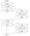
以下に、本実施の形態に係る製造システム100の動作について説明する。なお、当該動作に係る説明は、光学表示装置の製造方法の説明を兼ねている。 [Operation of optical display device manufacturing system]
Below, operation | movement of themanufacturing system 100 which concerns on this Embodiment is demonstrated. Note that the description related to the operation also serves as a description of a method of manufacturing the optical display device.
以下に、本実施の形態に係る製造システム100の動作について説明する。なお、当該動作に係る説明は、光学表示装置の製造方法の説明を兼ねている。 [Operation of optical display device manufacturing system]
Below, operation | movement of the
まず、図1に示すように、巻出部1から積層フィルム10を巻き出す(巻出工程)。その後、図2に示すように、ハーフカッター21によって偏光フィルム10bおよび粘着層をハーフカットし、保護フィルム10aをナイフエッジ23によって剥離する(剥離工程)。さらに、ニップローラ24・24aによって、粘着層を介して偏光フィルム10bが液晶パネル2の下面に圧着されることによって、偏光フィルム10bと液晶パネル2とを貼合する(貼合工程)。なお、剥離された保護フィルム10aは図示しない巻取部によって巻き取られ、回収される。
First, as shown in FIG. 1, the laminated film 10 is unwound from the unwinding portion 1 (unwinding step). Thereafter, as shown in FIG. 2, the polarizing film 10b and the adhesive layer are half-cut by the half cutter 21, and the protective film 10a is peeled by the knife edge 23 (peeling step). Further, the polarizing film 10b and the liquid crystal panel 2 are bonded together by the nip rollers 24 and 24a being pressed against the lower surface of the liquid crystal panel 2 via the adhesive layer (bonding step). The peeled protective film 10a is wound and collected by a winding unit (not shown).
次に、下面に偏光フィルム10bが貼合された液晶パネル2は、反転部26によって反転されると共に、搬送方向に沿った液晶パネル2の短辺が搬送方向に垂直となるように移動される(反転工程)。反転工程によって、液晶パネルが貼合されていない面が液晶パネル2の下面となる。
Next, the liquid crystal panel 2 having the polarizing film 10b bonded to the lower surface is reversed by the reversing unit 26 and moved so that the short side of the liquid crystal panel 2 along the transport direction is perpendicular to the transport direction. (Reversal process). The surface where the liquid crystal panel is not bonded becomes the lower surface of the liquid crystal panel 2 by the reversal process.
再度、巻出工程、剥離工程、貼合工程がなされ、液晶パネル2の下面に偏光フィルム110bが貼合され、液晶パネル2の両面に偏光フィルム10b・110bが貼合された光学表示装置が得られる。
An unwinding process, a peeling process, and a bonding process are performed again, and an optical display device in which the polarizing film 110b is bonded to the lower surface of the liquid crystal panel 2 and the polarizing films 10b and 110b are bonded to both surfaces of the liquid crystal panel 2 is obtained. It is done.
上記一連の工程において積層フィルム10を巻き出すにつれ、巻出部1に保持された積層フィルム10のロールの残量は減少していくこととなる。以下に偏光フィルム同士を連結させる連結工程について説明する。なお、巻出部101についても同様である。
As the laminated film 10 is unwound in the series of steps described above, the remaining amount of the roll of the laminated film 10 held by the unwinding unit 1 decreases. Below, the connection process which connects polarizing films is demonstrated. The same applies to the unwinding unit 101.
連結工程は、積層フィルム10を切断し、ライン側に残った(巻出部10の原反ロールR1から切り離された)積層フィルム10と、巻出部1aに設置された原反ロールR1aから巻き出された積層フィルム20とを連結する工程である。上記連結工程としては、(1)オペレーターによる手法と、(2)フィルム連結部3・13を用いる手法とを挙げることができる。
In the connecting step, the laminated film 10 is cut and wound from the laminated film 10 left on the line side (separated from the original roll R1 of the unwinding portion 10) and the original roll R1a installed in the unwinding portion 1a. This is a step of connecting the laminated film 20 that has been taken out. Examples of the connecting step include (1) a technique by an operator and (2) a technique using the film connecting portions 3 and 13.
まず、(1)のオペレーターによる手法について具体的に説明する。オペレーターにより偏光フィルム同士(積層フィルム同士)を連結させる場合、積層フィルム10の搬送速度を0m/min.とした後(積層フィルム10を停止させた後)に、オペレーターが積層フィルム10(偏光フィルム10b)を切断する。次に、巻出部1aから積層フィルム20を巻き出し、積層フィルム20の端部を切断した後に、例えば、上述した片面粘着テープ5dを用いて連結する手法が挙げられる。
First, the method by the operator of (1) will be explained specifically. When connecting the polarizing films (laminate films) by an operator, the conveyance speed of the laminate film 10 is set to 0 m / min. (After stopping the laminated film 10), the operator cuts the laminated film 10 (polarizing film 10b). Next, after unwinding the laminated film 20 from the unwinding part 1a and cutting the end part of the laminated film 20, for example, a method of connecting using the above-described single-sided adhesive tape 5d can be used.
このように、本発明に係る製造システム100では、巻出部1・1aの2つの巻出部が並設して備えられている。よって、原反ロールR1を新たなロールに交換せずとも、原反ロールR1aを用いて即座に偏光フィルム同士(積層フィルム同士)を連結させることができ、速やかに積層フィルム20を巻き出すことができる。
Thus, in the manufacturing system 100 according to the present invention, the two unwinding portions of the unwinding portions 1 and 1a are provided in parallel. Therefore, without replacing the original roll R1 with a new roll, the polarizing films R1a can be used to immediately connect the polarizing films (laminate films), and the laminated film 20 can be quickly unwound. it can.
さらに、従来の巻出部が1箇所にのみ設置された製造システムとは異なり、運転中に空いている方の巻出部において、原反ロールの交換作業が行える為、交換作業に必要な時間を削減することができる。その結果、光学表示装置の製造時間を短縮することが可能である。製造システム100では、積層フィルム10・20の連結を終えた後、積層フィルム20を巻き出す間に、巻出部1の原反ロールR1を新たなロールに交換する。積層フィルム20の残量が減少した場合、同様に積層フィルム20と積層フィルム10とを連結することももちろん可能である。
Furthermore, unlike the manufacturing system in which the conventional unwinding unit is installed only at one place, the original roll roll can be replaced at the unwinding unit that is vacant during operation. Can be reduced. As a result, it is possible to shorten the manufacturing time of the optical display device. In the manufacturing system 100, after the connection of the laminated films 10 and 20 is finished, the raw roll R1 of the unwinding unit 1 is replaced with a new roll while the laminated film 20 is unwound. When the remaining amount of the laminated film 20 is reduced, it is of course possible to connect the laminated film 20 and the laminated film 10 in the same manner.
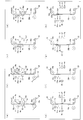
次に、フィルム連結部3・13を用いる場合について図7を用いて具体的に説明する。フィルム連結部103・113を用いる場合も同様である。図7は、製造システム100による連結工程を示す工程図である。原反ロールR1の残量が減少し、積層フィルム10(偏光フィルム10b)の搬送速度を0m/min.とした後に、図7(a)のように、吸着部4・4aおよび切断貼合部5を偏光フィルム10b(積層フィルム10)に対して垂直方向に移動させる。次に、吸着部4・4aの吸着機構9によって、偏光フィルム10bを吸着して保持する(吸着工程)。
Next, the case where the film connecting portions 3 and 13 are used will be specifically described with reference to FIG. The same applies to the case where the film connecting portions 103 and 113 are used. FIG. 7 is a process diagram illustrating a connection process by the manufacturing system 100. The remaining amount of the raw fabric roll R1 decreases, and the conveying speed of the laminated film 10 (polarizing film 10b) is reduced to 0 m / min. Then, as shown in FIG. 7A, the adsorbing parts 4 and 4a and the cutting and bonding part 5 are moved in the vertical direction with respect to the polarizing film 10b (laminated film 10). Next, the polarizing film 10b is sucked and held by the suction mechanism 9 of the suction parts 4 and 4a (suction process).
この際、切断貼合部5では、切断支持面5aが偏光フィルム10bに接触している。その後、図7(b)に示すように、図示しない切断機を開口6に沿って移動させて積層フィルム10を切断する(切断工程)。切断後、切断貼合部5を偏光フィルム10bに対して垂直方向であって、偏光フィルム10bから遠ざかる方向(図中左側)に移動させる。その後、時計回りに1/3周回転させ、偏光フィルム10bに対して垂直方向であって、偏光フィルム10bへ接近する方向(図中右側)に移動させる。これにより、図7(c)に示すように、片面粘着テープ5d(図示せず)と対向する偏光フィルム10bの切断線を覆うように(切断線を越えて)、貼合面5bの片面粘着テープ5dを貼り合わせる(貼合工程)。上記切断線とは、切断工程によって、偏光フィルム10bに生じた切断面のうち、貼合面5bと対向する辺を示す。貼合工程では、片面粘着テープ5dは上記切断線を覆うように配置される、すなわち、片面粘着テープ5dは、偏光フィルム10bの切断線を越えて、偏光フィルム10bが存在しない部分にも配置されている。
At this time, in the cutting and bonding unit 5, the cutting support surface 5a is in contact with the polarizing film 10b. Then, as shown in FIG.7 (b), the cutting machine which is not shown in figure is moved along the opening 6, and the laminated | multilayer film 10 is cut | disconnected (cutting process). After cutting, the cut bonding part 5 is moved in the direction perpendicular to the polarizing film 10b and away from the polarizing film 10b (left side in the figure). Then, it is rotated clockwise by 1/3 turn and moved in a direction perpendicular to the polarizing film 10b and close to the polarizing film 10b (right side in the figure). Thereby, as shown in FIG.7 (c), the single-sided adhesive of the bonding surface 5b is covered so that the cutting line of the polarizing film 10b facing the single-sided adhesive tape 5d (not shown) may be covered (beyond a cutting line). The tape 5d is bonded together (bonding process). The said cutting line shows the edge | side which opposes the bonding surface 5b among the cut surfaces produced in the polarizing film 10b by the cutting process. In the bonding step, the single-sided adhesive tape 5d is arranged so as to cover the cutting line, that is, the single-sided adhesive tape 5d is arranged in a portion where the polarizing film 10b does not exist beyond the cutting line of the polarizing film 10b. ing.
さらに、積層フィルム20に対しても、図7(d)~(e)と同様にして、保護フィルム20aに片面粘着テープ15dを粘着する。上述した部材と同様の部材には同一の名称を付し、その説明を省略する。
Further, the single-sided adhesive tape 15d is adhered to the protective film 20a in the same manner as in FIGS. 7D to 7E with respect to the laminated film 20. The same members as those described above are given the same names, and the description thereof is omitted.
まず、積層フィルム20を巻出部1aから巻き出して、図7(a)と同様に、図示しない切断機を、切断支持面15aに形成された開口に沿って移動させて積層フィルム20を切断する。切断後、切断貼合部15を保護フィルム20aに対して垂直方向であって、保護フィルム20aから遠ざかる方向(図中右側)に移動させる。その後、反時計回りに1/3周回転させ、保護フィルム20aに対して垂直方向であって、保護フィルム20aへ近接する方向(図中左側)に移動させる。これにより、図7(e)に示すように、貼合面15bの片面粘着テープ15dと対向する保護フィルム20aの切断線を覆うように、片面粘着テープ15dを貼り付けることができる。
First, the laminated film 20 is unwound from the unwinding portion 1a, and a cutting machine (not shown) is moved along the opening formed in the cutting support surface 15a to cut the laminated film 20 as in FIG. To do. After cutting, the cut bonding part 15 is moved in a direction perpendicular to the protective film 20a and away from the protective film 20a (right side in the figure). Then, it is rotated counterclockwise by 1/3 round and moved in a direction perpendicular to the protective film 20a and close to the protective film 20a (left side in the figure). Thereby, as shown in FIG.7 (e), the single-sided adhesive tape 15d can be affixed so that the cutting line of the protective film 20a facing the single-sided adhesive tape 15d of the bonding surface 15b may be covered.
次に、図7(f)に示すように、吸着部4・4aおよび切断貼合部5(フィルム連結装置3)を吸着部14・14aおよび切断貼合部15(フィルム連結部13)に近接させ、積層フィルム10および積層フィルム20の切断面同士を合わせる(近接工程)。これにより、偏光フィルム10bの切断線を覆う片面粘着テープ5dおよび保護フィルム20aの切断線を覆う片面粘着テープ15dのうち、切断線を越えた部分が、偏光フィルム20bおよび保護フィルム10aに貼合する。積層フィルム10・20が連結される。すなわち、偏光フィルム10b・20bを保護する保護フィルム10a・20a同士、および両偏光フィルム10b・20b同士がそれぞれ連結される。切断線を越えた部分は、偏光フィルム10b・保護フィルム20aに貼合していない部分と換言できる。
Next, as shown to FIG.7 (f), adsorption | suction part 4 * 4a and the cutting | disconnection bonding part 5 (film connection apparatus 3) adjoin to adsorption | suction part 14 * 14a and the cutting | disconnection bonding part 15 (film connection part 13). The cut surfaces of the laminated film 10 and the laminated film 20 are matched (proximity process). Thereby, the part beyond the cutting line sticks to the polarizing film 20b and the protective film 10a among the single-sided adhesive tape 5d which covers the cutting line of the polarizing film 10b, and the single-sided adhesive tape 15d which covers the cutting line of the protective film 20a. . The laminated films 10 and 20 are connected. That is, the protective films 10a and 20a that protect the polarizing films 10b and 20b and the polarizing films 10b and 20b are connected to each other. The part beyond the cutting line can be rephrased as a part not bonded to the polarizing film 10b / protective film 20a.
図7(f)では、フィルム連結部3をフィルム連結部13へ近接させたが、フィルム連結部13をフィルム連結部3へ近接させてもよく、また、フィルム連結部3・13を互いに近接させてもよい。
In FIG. 7 (f), the film connecting portion 3 is brought close to the film connecting portion 13, but the film connecting portion 13 may be brought close to the film connecting portion 3, and the film connecting portions 3 and 13 are brought close to each other. May be.
積層フィルム10・20を連結させた後には、準備工程として、図7(g)に示すように、フィルム連結部3・13をそれぞれ偏光フィルム10b・保護フィルム20aに対して垂直方向であって、遠ざかる方向へ移動させる。その後、切断貼合部5を反時計回りに1/3周回転させ、切断貼合部15を時計回りに1/3周回転させる。これにより、切断支持面5aが偏光フィルム10b側に向き、切断支持面15aが保護フィルム20a側に向くことになる(図7(h)の位置)。これにより、一連の工程が終了する。なお、貼合面5c・15cには、片面粘着テープ5d・15dが予め吸着された状態にて備えられている。このため、巻出部1に新たな原反ロールR1が設置された後に、積層フィルム20に対して図7(a)~(c)と左右逆の同様の工程を行い、積層フィルム10に対して図7(d)~(e)と左右逆の同様の工程を行う。そして、上述したように図7(f)~(h)と同様の工程を経て、積層フィルム20・10を連結させることができる。また、使用した片面粘着テープ5d・15dを補充することによって、連続して積層フィルム同士(偏光フィルム同士)を連結することももちろん可能である。
After connecting the laminated films 10 and 20, as a preparation step, as shown in FIG. 7 (g), the film connecting portions 3 and 13 are perpendicular to the polarizing film 10b and the protective film 20a, respectively. Move away. Thereafter, the cutting and bonding unit 5 is rotated counterclockwise by 3, and the cutting and bonding unit 15 is rotated clockwise by 3. Thereby, the cutting support surface 5a faces the polarizing film 10b side, and the cutting support surface 15a faces the protective film 20a side (position in FIG. 7 (h)). Thereby, a series of processes are completed. The bonding surfaces 5c and 15c are provided with a single-sided adhesive tape 5d and 15d adsorbed in advance. For this reason, after a new raw fabric roll R1 is installed in the unwinding section 1, the same process as that shown in FIGS. Then, the same steps as the right and left are performed in the same manner as in FIGS. Then, as described above, the laminated films 20 and 10 can be connected through the same steps as in FIGS. In addition, it is of course possible to continuously connect the laminated films (polarized films) by replenishing the used single-sided adhesive tapes 5d and 15d.
上述のように、フィルム連結部3・13を用いた連結工程の場合、オペレーターによる連結工程と比較して、偏光フィルムの吸着、切断、貼合をより短時間に、また、より正確に行うことが可能となるため好ましい。
As described above, in the case of the connecting step using the film connecting portions 3 and 13, the polarizing film is adsorbed, cut, and bonded in a shorter time and more accurately than the connecting step by the operator. Is preferable.
具体的には、製造システム100において、オペレーターによる連結工程の場合、10分程度必要であったが、フィルム連結部3・13を用いた場合、1分以下とすることができた。
Specifically, in the manufacturing system 100, in the case of the connecting step by the operator, about 10 minutes were required, but when the film connecting portions 3 and 13 were used, the time could be reduced to 1 minute or less.
なお、製造システム100において、巻出部1のみを使用し、巻出部1aを使用せず、さらにフィルム連結部3・13も使用しない場合、オペレーターは巻出部1に新たな原反ロールR1を設置した後に積層フィルム10を連結する必要がある。この場合、連結工程には30分程度必要である。このため、本実施の形態に係る製造システム100が有益であることは明らかである。
In addition, in the manufacturing system 100, when only the unwinding part 1 is used, the unwinding part 1a is not used, and the film connecting parts 3 and 13 are not used, the operator adds a new raw roll R1 to the unwinding part 1. It is necessary to connect the laminated film 10 after installing. In this case, the connecting process requires about 30 minutes. For this reason, it is clear that the manufacturing system 100 according to the present embodiment is useful.
〔光学表示装置の製造システムの変形例〕
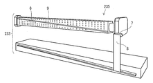
本発明に係るフィルム連結部の変形例である製造システム200について説明する。図8は、製造システム200を示す側面図である。同図に示すように、製造システム100と異なる点として製造システム200は、フィルム連結部3・103に代えてフィルム保持切断部33・133を、フィルム連結部13・113に代えて第1連結材貼合部36・136を備えている。なお、図8では、フィルム保持切断部の切断機の図示を省略している。また、製造システム200は、さらに第2連結材貼合部36a・136aを備えている。 [Modification of optical display device manufacturing system]
Themanufacturing system 200 which is a modification of the film connection part which concerns on this invention is demonstrated. FIG. 8 is a side view showing the manufacturing system 200. As shown in the figure, the manufacturing system 200 differs from the manufacturing system 100 in that the film holding and cutting portions 33 and 133 are replaced with the film connecting portions 3 and 103, and the first connecting material is replaced with the film connecting portions 13 and 113. Bonding portions 36 and 136 are provided. In addition, in FIG. 8, illustration of the cutting machine of a film holding | maintenance cutting part is abbreviate | omitted. Moreover, the manufacturing system 200 is further provided with the 2nd connection material bonding part 36a * 136a.
本発明に係るフィルム連結部の変形例である製造システム200について説明する。図8は、製造システム200を示す側面図である。同図に示すように、製造システム100と異なる点として製造システム200は、フィルム連結部3・103に代えてフィルム保持切断部33・133を、フィルム連結部13・113に代えて第1連結材貼合部36・136を備えている。なお、図8では、フィルム保持切断部の切断機の図示を省略している。また、製造システム200は、さらに第2連結材貼合部36a・136aを備えている。 [Modification of optical display device manufacturing system]
The
フィルム保持切断部33および第1連結材貼合部36は、巻出部1から巻出された積層フィルム10(第1偏光フィルム)および巻出部1aから巻出された偏光フィルムである積層フィルム20(第2偏光フィルム)の搬送位置を介在して配置されている。換言すると、フィルム保持切断部33および第1連結材貼合部36の間に、積層フィルム10および積層フィルム20が搬送されるように、フィルム保持切断部33および第1連結材貼合部36が配置されている。
The film holding and cutting part 33 and the first connecting material bonding part 36 are a laminated film 10 (first polarizing film) unwound from the unwinding part 1 and a laminated film which is a polarizing film unwound from the unwinding part 1a. It arrange | positions through the conveyance position of 20 (2nd polarizing film). In other words, the film holding and cutting part 33 and the first connecting material bonding part 36 are arranged so that the laminated film 10 and the laminated film 20 are conveyed between the film holding and cutting part 33 and the first connecting material bonding part 36. Has been placed.
同図では、フィルム保持切断部33が、積層フィルム10に対向するように配置されており、第1連結材貼合部36が積層フィルム20に対向するように配置されている。また、フィルム保持切断部33から積層フィルム10の巻出方向に第2連結材貼合部36aが配置されるように製造システム200に備えられており、第2連結材貼合部36aは、積層フィルム10に向かうように配置されている。
In the same figure, the film holding / cutting part 33 is arranged so as to face the laminated film 10, and the first connecting material bonding part 36 is arranged so as to face the laminated film 20. Moreover, the manufacturing system 200 is equipped so that the 2nd connection material bonding part 36a may be arrange | positioned in the unwinding direction of the laminated | multilayer film 10 from the film holding | maintenance cutting part 33, and the 2nd connection material bonding part 36a is laminated | stacked. It is arranged so as to face the film 10.
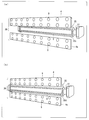
図9は、フィルム保持切断部33を示す斜視図である。フィルム保持切断部33は、フィルム保持部35および切断機7を備えており、切断機7は台部8にて支持されている。フィルム保持部35は、積層フィルム10と対向するフィルム保持部35に吸着機構9を備えており、フィルム保持部35には、溝状の開口6が形成されている。吸着機構9はフィルム連結部3が備えるものと同様である。フィルム保持切断部33では、フィルム連結部3とは異なり、積層フィルム10を吸着または脱着する吸着機構9が開口6が形成された面に備えられている。しかし、この構造に限定されず、フィルム連結部3のように、フィルム保持部35に吸着機構9を備えず、吸着部4・4aを備える構成であってもよい。フィルム保持部35では、開口6が積層フィルム10(偏光フィルム10a)の幅方向に沿って水平に形成されており、切断機7は、開口6に沿って積層フィルム10・20を切断する。
FIG. 9 is a perspective view showing the film holding / cutting portion 33. The film holding / cutting unit 33 includes a film holding unit 35 and a cutting machine 7, and the cutting machine 7 is supported by the base 8. The film holding unit 35 includes the suction mechanism 9 in the film holding unit 35 facing the laminated film 10, and the film holding unit 35 has a groove-shaped opening 6 formed therein. The suction mechanism 9 is the same as that provided in the film connecting portion 3. In the film holding and cutting part 33, unlike the film connecting part 3, an adsorption mechanism 9 that adsorbs or desorbs the laminated film 10 is provided on the surface on which the opening 6 is formed. However, the structure is not limited to this structure, and the film holding unit 35 may not include the suction mechanism 9 and may include the suction units 4 and 4a as in the film connection unit 3. In the film holding unit 35, the opening 6 is formed horizontally along the width direction of the laminated film 10 (polarizing film 10 a), and the cutting machine 7 cuts the laminated films 10 and 20 along the opening 6.
吸着機構9は、開口6を境界としてフィルム保持部35に形成されている。積層フィルム10が切断されることで積層フィルム10は二分割される。吸着機構9は開口6を境界として二分される吸着機構ごとに吸着または脱着を制御でき、切断された積層フィルム10のうち、巻出方向の積層フィルム10と、巻出方向と逆方向の積層フィルム10とを選択的に吸着または脱着できる。これにより、たとえば、積層フィルム10を切断した場合、巻出方向と逆方向の積層フィルム10のみを脱着することにより、巻出方向の積層フィルム10のみがフィルム保持部35に吸着された状態となる。その後、巻出方向と逆方向の積層フィルム10が吸着されていた位置に、切断された積層フィルム20のうち、巻出方向と逆方向の積層フィルム20を移動させることによって、巻出方向の積層フィルム10と、巻出方向と逆方向の積層フィルム20とを互いの切断面が対向した状態とすることができる。
The suction mechanism 9 is formed in the film holding unit 35 with the opening 6 as a boundary. The laminated film 10 is divided into two parts by cutting the laminated film 10. The adsorption mechanism 9 can control adsorption or desorption for each adsorption mechanism divided into two with the opening 6 as a boundary. Among the cut laminated films 10, the laminated film 10 in the unwinding direction and the laminated film in the direction opposite to the unwinding direction 10 can be selectively adsorbed or desorbed. Thereby, for example, when the laminated film 10 is cut, only the laminated film 10 in the unwinding direction is detached and only the laminated film 10 in the unwinding direction is adsorbed to the film holding unit 35. . Thereafter, the laminated film 20 in the direction opposite to the unwinding direction is moved to the position where the laminated film 10 in the direction opposite to the unwinding direction is adsorbed. The film 10 and the laminated film 20 in the direction opposite to the unwinding direction can be in a state in which the cut surfaces face each other.
図10は、フィルム保持切断部33の変形例であるフィルム保持切断部233を示す斜視図である。フィルム保持部235では、開口6がフィルム保持部235に斜め方向に形成されている。これにより、切断機7は、積層フィルム10の幅方向に対して斜め方向に積層フィルム10および積層フィルム20の両方を切断する。当該構成によれば、切断した積層フィルム同士を連結した際に、連結部分に加わる応力が低減されるので好ましい。
FIG. 10 is a perspective view showing a film holding / cutting portion 233 which is a modification of the film holding / cutting portion 33. In the film holding part 235, the opening 6 is formed in the film holding part 235 in an oblique direction. Thereby, the cutting machine 7 cuts both the laminated film 10 and the laminated film 20 in an oblique direction with respect to the width direction of the laminated film 10. According to the said structure, when the laminated | multilayer film which cut | disconnected are connected, since the stress added to a connection part is reduced, it is preferable.
図11(a)・(b)は、第1連結材貼合部36を示す斜視図である。第1連結材貼合部36は、吸着部4・4aおよび連結材保持部37を備えている。連結材保持部37は、吸着機構9を備えており、片面粘着テープ(連結材)35dを吸着することにより保持している。一方、吸着部4・4aは積層フィルム20を吸着または脱着する吸着機構9を備えている。
11 (a) and 11 (b) are perspective views showing the first connecting material bonding portion 36. FIG. The first connecting material bonding part 36 includes adsorption parts 4 and 4 a and a connecting material holding part 37. The connecting material holding part 37 includes the suction mechanism 9 and holds the single-sided adhesive tape (connecting material) 35d by suction. On the other hand, the adsorbing portions 4 and 4 a include an adsorbing mechanism 9 that adsorbs or desorbs the laminated film 20.
吸着部4・4aは、それぞれ独立して吸着または脱着を制御でき、切断された積層フィルム20のうち、巻出方向の積層フィルム20と、巻出方向と逆方向の積層フィルム20とを選択的に吸着または脱着できる。巻出方向の積層フィルム20は吸着部4にて吸着または脱着され、巻出方向と逆方向の積層フィルム20は吸着部4aにて吸着または脱着される。
The adsorbing portions 4 and 4a can independently control adsorption or desorption, and among the cut laminated films 20, the laminated film 20 in the unwinding direction and the laminated film 20 in the direction opposite to the unwinding direction are selectively used. Can be adsorbed or desorbed. The laminated film 20 in the unwinding direction is adsorbed or desorbed by the adsorption unit 4, and the laminated film 20 in the direction opposite to the unwinding direction is adsorbed or desorbed by the adsorption unit 4a.
第1連結材貼合部36は、積層フィルム20に対して移動可能であり、吸着部4・4aおよび連結材保持部37はそれぞれ単独で移動可能である。図11(a)では、吸着部4・4aに比較して、連結材保持部37は積層フィルム20から離間して配置されており、吸着部4・4aは、積層フィルム20に接近して配置されている。
The 1st connection material bonding part 36 is movable with respect to the laminated | multilayer film 20, and the adsorption | suction part 4 * 4a and the connection material holding | maintenance part 37 are each movable independently. In FIG. 11 (a), the connecting material holding part 37 is arranged away from the laminated film 20 as compared with the adsorbing parts 4 and 4a, and the adsorbing parts 4 and 4a are arranged close to the laminated film 20. Has been.
図11(b)は、連結材保持部37が積層フィルム20に接近した状態を示しており、吸着部4、片面粘着テープ35dおよび吸着部4aが同一面内に位置するように、連結材保持部37が配置されている。連結材保持部37が積層フィルム20の方向へ移動することにより、片面粘着テープ35dを積層フィルム20に貼合することができる。なお、連結材保持部37は、略三角柱形状を有しており、片面粘着テープ35dを保持する面をさらに2面備えている。この2面には、予め片面粘着テープ35dを保持することができ、連結材保持部37を回転させることによって、片面粘着テープ35dを補充せずとも、再度、片面粘着テープ35dを積層フィルムに貼合することができ、積層フィルム同士を連結することができる(後述する第2連結工程)。
FIG. 11B shows a state in which the connecting material holding portion 37 is close to the laminated film 20, and the connecting material is held so that the suction portion 4, the single-sided adhesive tape 35 d and the suction portion 4 a are located in the same plane. A portion 37 is arranged. The single-sided adhesive tape 35 d can be bonded to the laminated film 20 by the connecting material holding part 37 moving in the direction of the laminated film 20. In addition, the connection material holding | maintenance part 37 has a substantially triangular prism shape, and is further provided with two surfaces which hold | maintain the single-sided adhesive tape 35d. A single-sided adhesive tape 35d can be held in advance on these two surfaces, and the single-sided adhesive tape 35d is again applied to the laminated film without replenishing the single-sided adhesive tape 35d by rotating the connecting material holding portion 37. The laminated films can be connected to each other (second connecting step described later).
また、第2連結材貼合部36aは、第1連結材貼合部36と同様の構成を有しており、吸着部4・4aおよび連結材保持部37aを備えている。巻出方向の積層フィルム10は吸着部4にて吸着または脱着され、巻出方向と逆方向の積層フィルム10は吸着部4aにて吸着または脱着される。
Moreover, the 2nd connection material bonding part 36a has the structure similar to the 1st connection material bonding part 36, and is provided with the adsorption | suction part 4 * 4a and the connection material holding part 37a. The laminated film 10 in the unwinding direction is adsorbed or desorbed by the adsorption unit 4, and the laminated film 10 in the direction opposite to the unwinding direction is adsorbed or desorbed by the adsorption unit 4a.
製造システム200のフィルム保持切断部33、第1連結材貼合部36および第2連結材貼合部36aによって、積層フィルム10・20を連結する工程について図12を用いて説明する。フィルム保持切断部133、第1連結材貼合部136および第2連結材貼合部136aによって、積層フィルム110・120を連結する場合も同様である。図12は、製造システム100による連結工程を示す工程図である。
The process of connecting the laminated films 10 and 20 by the film holding and cutting part 33, the first connecting material bonding part 36, and the second connecting material bonding part 36a of the manufacturing system 200 will be described with reference to FIG. The same applies to the case where the laminated films 110 and 120 are connected by the film holding and cutting part 133, the first connecting material bonding part 136, and the second connecting material bonding part 136a. FIG. 12 is a process diagram showing a connection process by the manufacturing system 100.
まず、原反ロールR1の残量が減少し、積層フィルム10(偏光フィルム10b)の搬送速度を0m/min.とした後に、図12(a)のように、フィルム保持部35を偏光フィルム10b(積層フィルム10)に対して垂直方向に移動させて、吸着機構9によって偏光フィルム10bを吸着する。一方、積層フィルム20の一端はフィルム吸着ロール16aに固定されており、積層フィルム20に対して、吸着部4・4aを移動させ、吸着部4・4aの吸着機構9によって、保護フィルム10aを吸着して保持する(吸着工程)。フィルム吸着ロール16aは、積層フィルムを吸着して保持するローラであり、補充用の積層フィルム(偏光フィルム)の一端を保持するために使用される。なお、同図では、補充用の積層フィルムは積層フィルム20であるが、積層フィルム20に積層フィルム10を連結する場合、積層フィルム10の一端がフィルム吸着ローラに保持されるように、フィルム吸着ローラが配置される。
First, the remaining amount of the raw roll R1 decreases, and the transport speed of the laminated film 10 (polarizing film 10b) is set to 0 m / min. Then, as shown in FIG. 12A, the film holding unit 35 is moved in the vertical direction with respect to the polarizing film 10 b (laminated film 10), and the polarizing film 10 b is adsorbed by the adsorbing mechanism 9. On the other hand, one end of the laminated film 20 is fixed to the film adsorption roll 16a, and the adsorption portions 4 and 4a are moved relative to the laminated film 20, and the protective film 10a is adsorbed by the adsorption mechanism 9 of the adsorption portions 4 and 4a. And hold (adsorption process). The film adsorption roll 16a is a roller that adsorbs and holds the laminated film, and is used to hold one end of the supplementary laminated film (polarizing film). In the figure, the supplementary laminated film is the laminated film 20, but when the laminated film 10 is connected to the laminated film 20, the film adsorbing roller is arranged so that one end of the laminated film 10 is held by the film adsorbing roller. Is placed.
吸着工程の後、積層フィルム10と積層フィルム20とが隣接するように、吸着部4・4aを積層フィルム10に向かって移動させる。この状態で、開口に沿って切断機7を移動させて、積層フィルム10・20を切断する。
After the adsorption step, the adsorbing portions 4 and 4a are moved toward the laminated film 10 so that the laminated film 10 and the laminated film 20 are adjacent to each other. In this state, the cutting machine 7 is moved along the opening to cut the laminated films 10 and 20.
図12(b)に示すように、切断後、巻出方向と反対側の積層フィルム10(下側の積層フィルム10)を吸着するフィルム保持部35の吸着機構9の吸着を解除し、この積層フィルム10のみが脱着され、フィルム保持部35から離れる。一方、巻出方向の積層フィルム20(上側の積層フィルム20)を吸着する吸着部4の吸着機構9の吸着を解除し、この積層フィルム20のみが脱着され、吸着部4から離れる。
As shown in FIG. 12B, after cutting, the adsorption of the adsorption mechanism 9 of the film holding unit 35 that adsorbs the laminated film 10 (lower laminated film 10) opposite to the unwinding direction is released, and this lamination is performed. Only the film 10 is detached and separated from the film holding portion 35. On the other hand, the suction of the suction mechanism 9 of the suction portion 4 that sucks the laminated film 20 (upper laminated film 20) in the unwinding direction is released, and only this laminated film 20 is detached and separated from the suction portion 4.
さらに、図12(c)に示すように、巻出方向と逆方向の積層フィルム20(下側の積層フィルム20)を吸着する吸着部4aをフィルム保持部35の方向へ移動させる。巻出方向と逆方向の積層フィルム20は、巻出方向と逆方向の積層フィルム10が配置されていた位置に移動され、巻出方向の積層フィルム10と、巻出方向と逆方向の積層フィルム20とを互いの切断面が対向した状態となる。巻出方向と逆方向の積層フィルム20は、フィルム保持部35の吸着機構9によって吸着され、吸着部4aによる吸着は解除される。
Furthermore, as shown in FIG. 12 (c), the suction part 4 a that sucks the laminated film 20 (lower laminated film 20) in the direction opposite to the unwinding direction is moved toward the film holding part 35. The laminated film 20 in the direction opposite to the unwinding direction is moved to the position where the laminated film 10 in the direction opposite to the unwinding direction has been arranged, and the laminated film 10 in the direction of unwinding and the laminated film in the direction opposite to the unwinding direction. 20 is in a state where the cut surfaces face each other. The laminated film 20 in the direction opposite to the unwinding direction is adsorbed by the adsorption mechanism 9 of the film holding unit 35, and the adsorption by the adsorption unit 4a is released.
そして、図12(d)に示すように、連結材保持部37をフィルム保持部35の方向へ移動させることによって、巻出方向の積層フィルム10と巻出方向と逆方向の積層フィルム20とに両積層フィルムの切断線を越えて片面粘着テープ35dが貼合される。
And as shown in FIG.12 (d), by moving the connection material holding | maintenance part 37 to the direction of the film holding part 35, the laminated | multilayer film 10 of the unwinding direction and the laminated | multilayer film 20 of the reverse direction to an unwinding direction are used. A single-sided adhesive tape 35d is pasted across the cutting line of both laminated films.
貼合後、図12(e)に示すように、フィルム保持部35および連結材保持部37を連結された積層フィルムと逆方向へ移動させる。
After bonding, as shown in FIG.12 (e), the film holding | maintenance part 35 and the connection material holding | maintenance part 37 are moved to the reverse direction with the laminated film connected.
そして、図12(f)に示すように、連結された積層フィルムを巻出部1aから巻出し、搬送方向へ移動させる。連結された積層フィルムの切断線が連結材保持部37aと対向する位置にて、搬送を停止し、第2連結材貼合部36aの吸着部4によって、巻出方向の積層フィルム10を吸着し、第2連結材貼合部36aの吸着部4aによって、巻出方向と逆方向の積層フィルム20を吸着する。
And as shown in FIG.12 (f), the connected laminated | multilayer film are unwound from the unwinding part 1a, and are moved to a conveyance direction. At the position where the cutting line of the connected laminated film faces the connecting material holding part 37a, the conveyance is stopped, and the adhering part 4 of the second connecting material bonding part 36a adsorbs the laminated film 10 in the unwinding direction. The laminated film 20 in the direction opposite to the unwinding direction is adsorbed by the adsorbing part 4a of the second connecting material bonding part 36a.
図12(g)に示すように、連結材保持部37によって片面粘着テープ35dを貼合した積層フィルムの逆面に向かって、第2連結材貼合部36aを移動させる。連結材保持部37aは、連結された偏光フィルムの切断線に向かって移動し、連結材保持部37aが保持する片面粘着テープ35dが、積層フィルムの逆面において切断線を越えて貼合される。これにより、積層フィルム10・20は、両面に片面粘着テープ35dが貼合され、十分な強度を有した状態にて連結される。
As shown in FIG. 12 (g), the second connecting material bonding portion 36a is moved toward the opposite surface of the laminated film on which the single-sided adhesive tape 35d is bonded by the connecting material holding portion 37. The connecting material holding part 37a moves toward the cutting line of the connected polarizing film, and the single-sided adhesive tape 35d held by the connecting material holding part 37a is pasted across the cutting line on the reverse surface of the laminated film. . Thereby, the single-sided adhesive tape 35d is bonded on both surfaces, and the laminated films 10 and 20 are connected in a state having sufficient strength.
図12(h)に示すように、最後に、第2連結材貼合部36aの吸着部4、連結材保持部37aおよび吸着部4aが連結された積層フィルムから離れ、連結された積層フィルムの搬送が開始される。
As shown in FIG. 12 (h), finally, the adsorbing part 4, the connecting material holding part 37a and the adsorbing part 4a of the second connecting material bonding part 36a are separated from the connected laminated film, and the connected laminated film The conveyance is started.
〔製造システムの巻出部の動作〕
上記のように、本発明に係る製造システムは、2つの貼合機構にそれぞれ2つの巻出部を備え、さらに、同じ貼合機構が備える2つの巻出部から巻き出される積層フィルム(偏光フィルム)同士を連結する。 [Operation of unwinding part of manufacturing system]
As described above, the production system according to the present invention includes two unwinding portions in each of the two bonding mechanisms, and further a laminated film (polarizing film) unwound from the two unwinding portions included in the same bonding mechanism. ) Connect each other.
本発明の製造システムを用いた工程(光学表示装置の製造方法)には、(1)巻出工程、(2)連結工程および(3)交換工程が含まれる。上述したように、巻出工程は、巻出部から積層フィルム(偏光フィルム)を巻き出す工程であり、連結工程は、図7、図12にて説明したように、積層フィルム(偏光フィルム)同士を連結する工程である。なお、連結工程は、オペレーターが第1巻出部および第2巻出部から巻き出された積層フィルムを切断し、片面粘着テープによって、両積層フィルムを貼合する工程であってもよい。
The process (manufacturing method of the optical display device) using the manufacturing system of the present invention includes (1) unwinding process, (2) connecting process, and (3) replacing process. As described above, the unwinding step is a step of unwinding the laminated film (polarizing film) from the unwinding portion, and the connecting step is between the laminated films (polarizing film) as described with reference to FIGS. Is a step of connecting The connecting step may be a step in which the operator cuts the laminated film unwound from the first unwinding portion and the second unwinding portion, and bonds both the laminated films with a single-sided adhesive tape.
上記交換工程は、(1)巻出部1、101を原反ロールR1、R101の一方の巻芯方向に沿って水平に移動させ、(2)原反ロールR1、R101を新たな原反ロールに交換し、(3)巻出部1、101を新たな原反ロールの他方の巻芯方向に沿って水平に移動させて、巻出部1、101を元の位置に戻す、工程である。本発明に係る製造システムでは、巻出工程、連結工程および交換工程を、巻出部1、1a、101、101aを用いて行うことにより、原反ロールの交換時間を効率的に短縮できる。
In the replacement step, (1) the unwinding portions 1 and 101 are moved horizontally along one core direction of the original rolls R1 and R101, and (2) the original rolls R1 and R101 are moved to new original rolls. (3) The unwinding portions 1 and 101 are moved horizontally along the other core direction of the new original fabric roll, and the unwinding portions 1 and 101 are returned to their original positions. . In the manufacturing system according to the present invention, the unwinding process, the connecting process, and the replacing process are performed using the unwinding units 1, 1 a, 101, and 101 a, whereby the replacement time of the original roll can be efficiently shortened.
以下に、各巻出部の動作および積層フィルムの連結の順序について図13、14を用いて説明する。図13は、製造システム200の巻出部1、1a、101、101aの動作を示す平面図であり、図14は、製造システム200を用いた製造方法を示すフローチャートである。
Hereinafter, the operation of each unwinding part and the order of connecting the laminated films will be described with reference to FIGS. FIG. 13 is a plan view showing the operation of the unwinding portions 1, 1 a, 101, 101 a of the manufacturing system 200, and FIG. 14 is a flowchart showing a manufacturing method using the manufacturing system 200.
製造システム200は、巻出部1、1a、101、101aに原反ロールが設置された状態にて運転が開始される(図14のSTART)。まず、巻出部1・101からそれぞれ積層フィルム10・110が巻き出される(図14のS1:第1巻出工程)。光学表示装置の製造が行われ、原反ロールR1・R101の残量が尽きかけた際に、積層フィルム10・20、積層フィルム110・120の連結が行われる(図14のS2:第1連結工程)。その後、巻出部1a・101aから積層フィルム20・120が巻き出され(図14のS3:第2巻出工程)、光学表示装置の製造が継続される。
The manufacturing system 200 starts operation in a state where the raw fabric rolls are installed in the unwinding sections 1, 1 a, 101, 101 a (START in FIG. 14). First, the laminated films 10 and 110 are unwound from the unwinding portions 1 and 101, respectively (S1: first unwinding step in FIG. 14). When the optical display device is manufactured and the remaining amount of the raw rolls R1 and R101 is exhausted, the laminated films 10 and 20 and the laminated films 110 and 120 are connected (S2 in FIG. 14: first connection). Process). Thereafter, the laminated films 20 and 120 are unwound from the unwinding portions 1a and 101a (S3 in FIG. 14: second unwinding step), and the manufacture of the optical display device is continued.
S3の間、巻出部1・101に新たな原反ロールを交換するため、S4~S6として第1交換工程がなされる。始めに、図13(a)から(b)に示すように、巻出部1・101を積層フィルム10・110の一方の巻芯方向に沿って水平に移動可能させる(図14のS4)。次に、巻出部1・101の原反ロールR1・R101(偏光フィルム)を新たな原反ロール(偏光フィルム)に交換する(図14のS5)。交換後、巻出部1・101を新たな原反ロール(偏光フィルム)の他方の巻芯方向に沿って水平に移動可能させる(図14のS6、図13(b)から(c))。これにより、巻出部1・101を元の位置に戻す。
During S3, in order to replace the new raw roll with the unwinding unit 1/101, the first replacement process is performed as S4 to S6. First, as shown in FIGS. 13A to 13B, the unwinding portions 1 and 101 are horizontally movable along one core direction of the laminated films 10 and 110 (S4 in FIG. 14). Next, the raw rolls R1 and R101 (polarizing film) of the unwinding portions 1 and 101 are replaced with new raw rolls (polarizing film) (S5 in FIG. 14). After the replacement, the unwinding portions 1 and 101 are allowed to move horizontally along the other core direction of the new original fabric roll (polarizing film) (S6 in FIG. 14, FIGS. 13B to 13C). Thereby, the unwinding parts 1 and 101 are returned to the original positions.
S3において巻き出された原反ロールR1・R101の残量が尽きかけた際に、積層フィルム20・10、積層フィルム120・110の連結を行う(図14のS7:第2連結工程)。その後、巻出部1・101から積層フィルム10・110が巻き出され(図14のS8:第3巻出工程)、光学表示装置の製造が継続される。
When the remaining amount of the raw rolls R1 and R101 unwound in S3 is exhausted, the laminated films 20 and 10 and the laminated films 120 and 110 are connected (S7 in FIG. 14: second connecting step). Thereafter, the laminated films 10 and 110 are unwound from the unwinding portions 1 and 101 (S8 in FIG. 14: third unwinding step), and the manufacture of the optical display device is continued.
S8の間、巻出部1a・101aに新たな原反ロールを交換するため、S9~S11として第2交換工程がなされる。始めに、図13(c)から(d)に示すように、巻出部1a・101aを積層フィルム20・120の一方の巻芯方向に沿って水平に移動可能させる(図14のS9)。次に、巻出部1a・101aの原反ロールR1a・R101a(偏光フィルム)を新たな原反ロール(偏光フィルム)に交換する(図14のS10)。交換後、巻出部1a・101aを新たな原反ロール(偏光フィルム)の他方の巻芯方向に沿って水平に移動可能させる(図14のS11、図13(d)から(a))。これにより、巻出部1a・101aを元の位置に戻す。このように、巻出部の一連の動作について説明したが、S11からS1に戻り、光学表示装置の製造を継続することももちろん可能である。
During S8, a second exchange process is performed as S9 to S11 in order to exchange a new raw roll for the unwinding portions 1a and 101a. First, as shown in FIGS. 13C to 13D, the unwinding portions 1a and 101a are horizontally movable along one core direction of the laminated films 20 and 120 (S9 in FIG. 14). Next, the raw rolls R1a and R101a (polarizing film) of the unwinding portions 1a and 101a are replaced with new raw rolls (polarizing film) (S10 in FIG. 14). After the replacement, the unwinding portions 1a and 101a are moved horizontally along the other core direction of the new original fabric roll (polarizing film) (S11 in FIG. 14, FIG. 13 (d) to (a)). Thereby, the unwinding part 1a * 101a is returned to the original position. Thus, although a series of operation | movement of the unwinding part was demonstrated, it is also possible to return to S1 from S11 and to continue manufacture of an optical display apparatus.
本発明に係る光学表示装置の製造方法では、S3とS4~S6とを並行して行うと共に、S8とS9~S11とを並行して行う。そのため、積層フィルム(偏光フィルム)を巻き出している間に、積層フィルム(偏光フィルム)の原反ロールを交換でき、偏光フィルム同士の連結を速やかに行うことができる。したがって、製造システムを停止させる時間を抑制でき、短いタクトタイムにて光学表示装置を製造することが可能である。
In the method for manufacturing an optical display device according to the present invention, S3 and S4 to S6 are performed in parallel, and S8 and S9 to S11 are performed in parallel. Therefore, while unwinding the laminated film (polarizing film), the raw roll of the laminated film (polarizing film) can be exchanged, and the polarizing films can be quickly connected. Therefore, the time for stopping the manufacturing system can be suppressed, and the optical display device can be manufactured with a short tact time.
なお、本発明は、上述した各実施形態に限定されるものではなく、請求項に示した範囲で種々の変更が可能であり、異なる実施形態にそれぞれ開示された技術的手段を適宜組み合わせて得られる実施形態についても本発明の技術的範囲に含まれる。例えば、製造システムにおけるガイドローラの本数や、巻出部、巻取部、フィルム連結部および搬送機構の配置などは図示された配置に限定されるものではない。
The present invention is not limited to the above-described embodiments, and various modifications can be made within the scope of the claims, and the technical means disclosed in different embodiments can be appropriately combined. Such embodiments are also included in the technical scope of the present invention. For example, the number of guide rollers in the manufacturing system and the arrangement of the unwinding unit, the winding unit, the film connecting unit, and the transport mechanism are not limited to the illustrated arrangement.
なお、本発明の実施の形態には、以下の好ましい形態も含まれる。
It should be noted that the following preferred embodiments are also included in the embodiments of the present invention.
本発明の光学表示装置の製造システムでは、上記搬送機構は、液晶パネルの搬送方向が直線状であることが好ましい。
In the optical display device manufacturing system of the present invention, it is preferable that the transport mechanism has a linear liquid crystal panel transport direction.
液晶パネルの搬送方向が直角に曲がるような製造システムとは異なり、液晶パネルの搬送方向が直線状である構造であれば、製造システムの構造を直線に沿った構造に設計することができ、面積効率に優れた製造システムを提供できる。
Unlike a manufacturing system in which the transport direction of the liquid crystal panel is bent at a right angle, if the transport direction of the liquid crystal panel is a straight line, the structure of the manufacturing system can be designed to be a structure along the straight line. An efficient manufacturing system can be provided.
また、本発明の光学表示装置の製造システムでは、フィルム保持切断部および第1連結材貼合部が、第1巻出部から巻出された偏光フィルムである第1偏光フィルムおよび第2巻出部から巻出された偏光フィルムである第2偏光フィルムの搬送位置を介在して配置されており、上記フィルム保持切断部から第1偏光フィルムの巻出方向に第2連結材貼合部が備えられており、上記第2連結材貼合部は、第1偏光フィルムに向かって配置されており、上記フィルム保持切断部は、フィルム保持部と切断機とを備えており、上記フィルム保持部は、第1偏光フィルムを吸着または脱着する吸着機構を備え、上記切断機は、第1偏光フィルムおよび第2偏光フィルムの両方を切断するものであり、上記第1連結材貼合部は、第2偏光フィルムを吸着または脱着する吸着機構を備えた吸着部と共に、偏光フィルムの切断線を越えて貼合される連結材を保持する連結材保持部を備えており、上記第2連結材貼合部は、上記切断機によって切断された巻出方向の第1偏光フィルムおよび巻出方向と逆方向の第2偏光フィルムとを吸着または脱着する吸着機構を備えた吸着部と共に、偏光フィルムの切断線を越えて貼合される連結材を保持する連結材保持部を備えており、切断機によって切断された巻出方向の第1偏光フィルムと、巻出方向と逆方向の第2偏光フィルムとを互いの切断面が対向した状態にて、第1連結材貼合部によって、両偏光フィルムの切断線を越えて連結材を貼合し、第1連結材貼合部によって連結材を貼合した両偏光フィルムの逆面に、上記第2連結材貼合部によって、両偏光フィルムの切断線を越えて連結材を貼合することが好ましい。
Moreover, in the manufacturing system of the optical display device of the present invention, the first polarizing film and the second unwinding, in which the film holding and cutting part and the first connecting material bonding part are the polarizing films unwound from the first unwinding part. It arrange | positions via the conveyance position of the 2nd polarizing film which is a polarizing film unwound from the part, and a 2nd connection material bonding part is provided in the unwinding direction of the 1st polarizing film from the said film holding | maintenance cutting part. The second connecting material bonding portion is disposed toward the first polarizing film, the film holding / cutting portion includes a film holding portion and a cutting machine, and the film holding portion is And an adsorption mechanism that adsorbs or desorbs the first polarizing film, the cutting machine cuts both the first polarizing film and the second polarizing film, and the first connecting material bonding portion is a second one. Sucking polarizing film Or it has the connection part holding part which hold | maintains the connection material bonded beyond the cutting line of a polarizing film with the adsorption | suction part provided with the adsorption | suction mechanism to remove | desorb, The said 2nd connection material bonding part is the said cutting | disconnection. Pasting across the cutting line of the polarizing film, together with an adsorbing mechanism equipped with an adsorbing mechanism that adsorbs or desorbs the first polarizing film in the unwinding direction and the second polarizing film in the direction opposite to the unwinding direction. Each of the first and second polarizing films in the unwinding direction and the second polarizing film in the opposite direction to the unwinding direction are cut by a cutting machine. Opposite of both polarizing films in which the connecting material is pasted across the cutting line of both polarizing films by the first connecting material bonding portion and the connecting material is bonded by the first connecting material bonding portion in the opposed state. On the surface, by the second connecting material bonding part, It is preferable to be bonded the connecting member beyond the cutting line of the polarizing film.
また、本発明に係る光学表示装置の製造方法は、上記光学表示装置の製造システムを用いた光学表示装置の製造方法であって、第1巻出部から偏光フィルムを巻き出す第1巻出工程と、第1巻出部から巻き出された偏光フィルムと、第2巻出部から巻き出された偏光フィルムとを連結する第1連結工程と、第2巻出部から偏光フィルムを巻き出す第2巻出工程と、上記第2巻出工程の間、第1巻出部を偏光フィルムの一方の巻芯方向に沿って水平に移動可能させ、第1巻出部の偏光フィルムを新たな偏光フィルムに交換し、第1巻出部を偏光フィルムの他方の巻芯方向に沿って水平に移動可能させる第1交換工程と、第2巻出部から巻き出された偏光フィルムと、第1巻出部から巻き出された偏光フィルムとを連結する第2連結工程と、第1巻出部から偏光フィルムを巻き出す第3巻出工程と、上記第3巻出工程の間、第2巻出部を偏光フィルムの一方の巻芯方向に沿って水平に移動可能させ、第2巻出部の偏光フィルムを新たな偏光フィルムに交換し、第2巻出部を偏光フィルムの他方の巻芯方向に沿って水平に移動可能させる第2交換工程とを含む。
Moreover, the manufacturing method of the optical display device which concerns on this invention is a manufacturing method of the optical display apparatus using the said manufacturing system of an optical display apparatus, Comprising: The 1st unwinding process which unwinds a polarizing film from a 1st unwinding part. A first connecting step of connecting the polarizing film unwound from the first unwinding part and the polarizing film unwound from the second unwinding part, and unwinding the polarizing film from the second unwinding part. Between the two unwinding steps and the second unwinding step, the first unwinding portion can be moved horizontally along one core direction of the polarizing film, and the polarizing film of the first unwinding portion is newly polarized. The first exchange step for exchanging the film and moving the first unwinding portion horizontally along the other core direction of the polarizing film, the polarizing film unwound from the second unwinding portion, and the first winding A second connecting step of connecting the polarizing film unwound from the exit portion; During the third unwinding step of unwinding the polarizing film from the unwinding portion and the third unwinding step, the second unwinding portion can be moved horizontally along one core direction of the polarizing film, A second exchanging step of exchanging the polarizing film of the unwinding part with a new polarizing film and allowing the second unwinding part to move horizontally along the other core direction of the polarizing film.
本発明の製造システムによれば、光学表示装置の製造に際して、偏光フィルムの連結を速やかに行うことができ、光学表示装置の製造時間を短縮することができる。したがって、本発明は光学表示装置を製造する分野における利用が可能である。
According to the manufacturing system of the present invention, when the optical display device is manufactured, the polarizing films can be quickly connected, and the manufacturing time of the optical display device can be shortened. Therefore, the present invention can be used in the field of manufacturing an optical display device.
1・101 巻出部(第1巻出部)
1a・101a 巻出部(第2巻出部)
2 液晶パネル
3・103 フィルム連結部(第1フィルム連結部)
13・113 フィルム連結部(第2フィルム連結部)
4・4a・14・14a 吸着部
5・15 切断貼合部
5a・15a 切断支持面
5b・5c・15b・15c 貼合面
5d・15d・35d 片面粘着テープ(連結材)
6 開口
7・17 切断機
8 台部
9 吸着機構
10・110 積層フィルム(第1偏光フィルム)
10a・20a・110a 保護フィルム
10b・20b・110b 偏光フィルム
12 搬送機構
16・106 ガイドローラ
20・120 積層フィルム(第2偏光フィルム)
21・121 ハーフカッター
22・122 支持台
23・123 ナイフエッジ(剥離部)
24・24a・124・124a ニップローラ(貼合部)
25・125 巻取部
26 反転部
33・133 フィルム保持切断部
35 フィルム保持部
36・136 第1連結材貼合部
36a・136a 第2連結材貼合部
100・200 製造システム
D1 搬送方向
D2 巻芯方向 1.101 Unwinding part (first unwinding part)
1a / 101a Unwinding part (second unwinding part)
2 Liquid crystal panel 3.103 Film connecting part (first film connecting part)
13.113 Film connecting part (second film connecting part)
4 ・ 4a ・ 14 ・14a Adsorption part 5 ・ 15 Cutting and bonding part 5a ・ 15a Cutting support surface 5b ・ 5c ・ 15b ・ 15c Bonding surface 5d ・ 15d ・ 35d Single-sided adhesive tape (connecting material)
6Opening 7 · 17 Cutting machine 8 Base 9 Adsorption mechanism 10 · 110 Multilayer film (first polarizing film)
10a / 20a /110a Protective film 10b / 20b / 110b Polarizing film 12 Transport mechanism 16/106 Guide roller 20/120 Laminated film (second polarizing film)
21 ・ 121Half cutter 22 ・ 122 Support base 23 ・ 123 Knife edge (peeling part)
24, 24a, 124, 124a Nip roller (bonding part)
25/125Winding part 26 Reversing part 33/133 Film holding / cutting part 35 Film holding part 36/136 First connecting material bonding part 36a / 136a Second connecting material bonding part 100/200 Manufacturing system D1 Conveying direction D2 winding Core direction
1a・101a 巻出部(第2巻出部)
2 液晶パネル
3・103 フィルム連結部(第1フィルム連結部)
13・113 フィルム連結部(第2フィルム連結部)
4・4a・14・14a 吸着部
5・15 切断貼合部
5a・15a 切断支持面
5b・5c・15b・15c 貼合面
5d・15d・35d 片面粘着テープ(連結材)
6 開口
7・17 切断機
8 台部
9 吸着機構
10・110 積層フィルム(第1偏光フィルム)
10a・20a・110a 保護フィルム
10b・20b・110b 偏光フィルム
12 搬送機構
16・106 ガイドローラ
20・120 積層フィルム(第2偏光フィルム)
21・121 ハーフカッター
22・122 支持台
23・123 ナイフエッジ(剥離部)
24・24a・124・124a ニップローラ(貼合部)
25・125 巻取部
26 反転部
33・133 フィルム保持切断部
35 フィルム保持部
36・136 第1連結材貼合部
36a・136a 第2連結材貼合部
100・200 製造システム
D1 搬送方向
D2 巻芯方向 1.101 Unwinding part (first unwinding part)
1a / 101a Unwinding part (second unwinding part)
2 Liquid crystal panel 3.103 Film connecting part (first film connecting part)
13.113 Film connecting part (second film connecting part)
4 ・ 4a ・ 14 ・
6
10a / 20a /
21 ・ 121
24, 24a, 124, 124a Nip roller (bonding part)
25/125
Claims (5)
- 光学表示装置を製造する製造システムにおいて、
液晶パネルを搬送する搬送機構と、液晶パネルの下面に偏光フィルムを貼合する2つの貼合機構とを備え、
上記貼合機構は、
保護フィルムによって表面が保護された偏光フィルムを巻出す第1巻出部と、
第1巻出部から巻き出された偏光フィルムに連結される補充用の偏光フィルムを巻き出す第2巻出部と、
上記偏光フィルムから保護フィルムを剥離する剥離部と、
保護フィルムが剥離された偏光フィルムを液晶パネルの下面に貼合する貼合部と、
上記偏光フィルムから剥離された保護フィルムを巻取る巻取部とを含み、
上記搬送機構には、一方の貼合機構によって下面に偏光フィルムが貼合された液晶パネルを反転させる反転部が備えられており、
上記第1巻出部および第2巻出部は、偏光フィルムの巻芯方向に沿って水平に移動可能であり、上記第1巻出部および第2巻出部は、互いに並設されている光学表示装置の製造システム。 In a manufacturing system for manufacturing an optical display device,
A transport mechanism for transporting the liquid crystal panel, and two bonding mechanisms for bonding the polarizing film to the lower surface of the liquid crystal panel,
The bonding mechanism is
A first unwinding section for unwinding the polarizing film whose surface is protected by the protective film;
A second unwinding unit for unwinding a supplementary polarizing film connected to the polarizing film unwound from the first unwinding unit;
A peeling portion for peeling the protective film from the polarizing film;
A bonding part for bonding the polarizing film from which the protective film is peeled off to the lower surface of the liquid crystal panel;
A winding part for winding the protective film peeled off from the polarizing film,
The transport mechanism is provided with a reversing unit for reversing the liquid crystal panel on which the polarizing film is bonded to the lower surface by one bonding mechanism,
The first unwinding part and the second unwinding part are horizontally movable along the core direction of the polarizing film, and the first unwinding part and the second unwinding part are arranged in parallel with each other. An optical display manufacturing system. - 上記搬送機構は、液晶パネルの搬送方向が直線状である請求項1に記載の光学表示装置の製造システム。 2. The optical display device manufacturing system according to claim 1, wherein the transport mechanism has a linear transport direction of the liquid crystal panel.
- フィルム保持切断部および第1連結材貼合部が、第1巻出部から巻出された偏光フィルムである第1偏光フィルムおよび第2巻出部から巻出された偏光フィルムである第2偏光フィルムの搬送位置を介在して配置されており、
上記フィルム保持切断部から第1偏光フィルムの巻出方向に第2連結材貼合部が備えられており、上記第2連結材貼合部は、第1偏光フィルムに向かって配置されており、
上記フィルム保持切断部は、フィルム保持部と切断機とを備えており、
上記フィルム保持部は、第1偏光フィルムを吸着または脱着する吸着機構を備え、
上記切断機は、第1偏光フィルムおよび第2偏光フィルムの両方を切断するものであり、
上記第1連結材貼合部は、第2偏光フィルムを吸着または脱着する吸着機構を備えた吸着部と共に、偏光フィルムの切断線を越えて貼合される連結材を保持する連結材保持部を備えており、
上記第2連結材貼合部は、上記切断機によって切断された巻出方向の第1偏光フィルムおよび巻出方向と逆方向の第2偏光フィルムとを吸着または脱着する吸着機構を備えた吸着部と共に、偏光フィルムの切断線を越えて貼合される連結材を保持する連結材保持部を備えており、
切断機によって切断された巻出方向の第1偏光フィルムと、巻出方向と逆方向の第2偏光フィルムとを互いの切断面が対向した状態にて、第1連結材貼合部によって、両偏光フィルムの切断線を越えて連結材を貼合し、
第1連結材貼合部によって連結材を貼合した両偏光フィルムの逆面に、上記第2連結材貼合部によって、両偏光フィルムの切断線を越えて連結材を貼合する請求項1または2に記載の光学表示装置の製造システム。 The first polarizing film that is a polarizing film unwound from the first unwinding part and the second polarizing film that is a polarizing film unwound from the second unwinding part are the film holding and cutting part and the first connecting material bonding part. It is placed with the film transport position in between.
A second connecting material bonding part is provided in the unwinding direction of the first polarizing film from the film holding and cutting part, and the second connecting material bonding part is arranged toward the first polarizing film,
The film holding and cutting unit includes a film holding unit and a cutting machine,
The film holding unit includes an adsorption mechanism that adsorbs or desorbs the first polarizing film,
The cutting machine cuts both the first polarizing film and the second polarizing film,
The first linking material bonding section includes a linking material holding section for holding a linking material bonded across the cutting line of the polarizing film, together with an adsorption section having an adsorption mechanism for adsorbing or desorbing the second polarizing film. Has
The second connecting material bonding unit includes an adsorption mechanism that adsorbs or desorbs the first polarizing film in the unwinding direction and the second polarizing film in the direction opposite to the unwinding direction cut by the cutting machine. Along with the connecting material holding part that holds the connecting material to be pasted beyond the cutting line of the polarizing film,
Both the first polarizing film in the unwinding direction cut by the cutting machine and the second polarizing film in the direction opposite to the unwinding direction are opposed to each other by the first connecting material bonding portion in a state where the cut surfaces face each other. Pasting the connecting material beyond the cutting line of the polarizing film,
The connecting material is pasted across the cutting line of both polarizing films by the second connecting material bonding portion on the opposite surface of both polarizing films where the connecting material is bonded by the first connecting material bonding portion. Or the manufacturing system of the optical display apparatus of 2. - 上記切断機は、偏光フィルムの幅方向に対して斜め方向に第1偏光フィルムおよび第2偏光フィルムの両方を切断する請求項3に記載の光学表示装置の製造システム。 4. The optical display device manufacturing system according to claim 3, wherein the cutting machine cuts both the first polarizing film and the second polarizing film in an oblique direction with respect to the width direction of the polarizing film.
- 請求項1~4の何れか1項に記載の光学表示装置の製造システムを用いた光学表示装置の製造方法であって、
第1巻出部から偏光フィルムを巻き出す第1巻出工程と、
第1巻出部から巻き出された偏光フィルムと、第2巻出部から巻き出された偏光フィルムとを連結する第1連結工程と、
第2巻出部から偏光フィルムを巻き出す第2巻出工程と、
上記第2巻出工程の間、第1巻出部を偏光フィルムの一方の巻芯方向に沿って水平に移動可能させ、第1巻出部の偏光フィルムを新たな偏光フィルムに交換し、第1巻出部を偏光フィルムの他方の巻芯方向に沿って水平に移動可能させる第1交換工程と、
第2巻出部から巻き出された偏光フィルムと、第1巻出部から巻き出された偏光フィルムとを連結する第2連結工程と、
第1巻出部から偏光フィルムを巻き出す第3巻出工程と、
上記第3巻出工程の間、第2巻出部を偏光フィルムの一方の巻芯方向に沿って水平に移動可能させ、第2巻出部の偏光フィルムを新たな偏光フィルムに交換し、第2巻出部を偏光フィルムの他方の巻芯方向に沿って水平に移動可能させる第2交換工程とを含む光学表示装置の製造方法。 An optical display device manufacturing method using the optical display device manufacturing system according to any one of claims 1 to 4,
A first unwinding step of unwinding the polarizing film from the first unwinding section;
A first connecting step of connecting the polarizing film unwound from the first unwinding part and the polarizing film unwound from the second unwinding part;
A second unwinding step of unwinding the polarizing film from the second unwinding portion;
During the second unwinding step, the first unwinding portion can be moved horizontally along one core direction of the polarizing film, the polarizing film of the first unwinding portion is replaced with a new polarizing film, A first exchanging step of allowing one unwinding part to move horizontally along the other core direction of the polarizing film;
A second connecting step of connecting the polarizing film unwound from the second unwinding part and the polarizing film unwound from the first unwinding part;
A third unwinding step of unwinding the polarizing film from the first unwinding section;
During the third unwinding step, the second unwinding portion can be moved horizontally along one core direction of the polarizing film, the polarizing film of the second unwinding portion is replaced with a new polarizing film, A method for manufacturing an optical display device, comprising: a second exchanging step that allows the two unwinding portions to move horizontally along the other core direction of the polarizing film.
Priority Applications (2)
| Application Number | Priority Date | Filing Date | Title |
|---|---|---|---|
| KR1020147000298A KR101885943B1 (en) | 2011-06-09 | 2012-06-06 | Manufacturing system for optical display device and method for manufacturing optical display device |
| CN201280027910.8A CN103620485B (en) | 2011-06-09 | 2012-06-06 | The manufacture system of optical display and the manufacture method of optical display |
Applications Claiming Priority (2)
| Application Number | Priority Date | Filing Date | Title |
|---|---|---|---|
| JP2011129408A JP5667522B2 (en) | 2011-06-09 | 2011-06-09 | Optical display device manufacturing system and optical display device manufacturing method |
| JP2011-129408 | 2011-06-09 |
Publications (1)
| Publication Number | Publication Date |
|---|---|
| WO2012169553A1 true WO2012169553A1 (en) | 2012-12-13 |
Family
ID=47296112
Family Applications (1)
| Application Number | Title | Priority Date | Filing Date |
|---|---|---|---|
| PCT/JP2012/064599 WO2012169553A1 (en) | 2011-06-09 | 2012-06-06 | Manufacturing system for optical display device and method for manufacturing optical display device |
Country Status (5)
| Country | Link |
|---|---|
| JP (1) | JP5667522B2 (en) |
| KR (1) | KR101885943B1 (en) |
| CN (1) | CN103620485B (en) |
| TW (1) | TWI554381B (en) |
| WO (1) | WO2012169553A1 (en) |
Families Citing this family (3)
| Publication number | Priority date | Publication date | Assignee | Title |
|---|---|---|---|---|
| CN103439810B (en) * | 2013-08-14 | 2016-08-31 | 张家港康得新光电材料有限公司 | A kind of liquid crystal display film device and the method using this device pad pasting |
| JP2016038447A (en) * | 2014-08-06 | 2016-03-22 | 住友化学株式会社 | Pasting device, production system of optical display device, pasting method, and production method of optical display device |
| KR102470258B1 (en) * | 2015-12-22 | 2022-11-24 | 삼성디스플레이 주식회사 | Display apparatus and method for manufacturing the same |
Citations (2)
| Publication number | Priority date | Publication date | Assignee | Title |
|---|---|---|---|---|
| JPS61136850A (en) * | 1984-12-06 | 1986-06-24 | Ckd Corp | Automatic splicing method of film |
| JP2004361741A (en) * | 2003-06-05 | 2004-12-24 | Fuji Photo Film Co Ltd | Optical film pasting device and method |
Family Cites Families (16)
| Publication number | Priority date | Publication date | Assignee | Title |
|---|---|---|---|---|
| US3753833A (en) * | 1970-02-16 | 1973-08-21 | Butler Automatic Inc | Web supply apparatus |
| IT1269115B (en) * | 1994-06-16 | 1997-03-21 | Perini Fabio Spa | DEVICE FOR THE AUTOMATIC CHANGE OF TAPES OF TAPE MATERIAL |
| JP3132324B2 (en) | 1995-02-07 | 2001-02-05 | 凸版印刷株式会社 | Turret splicing control method for roll material |
| JPH0977316A (en) * | 1995-09-20 | 1997-03-25 | Nippon Reliance Kk | Automatic web splicing device |
| JP3706059B2 (en) * | 2001-11-16 | 2005-10-12 | 王子エンジニアリング株式会社 | Splicer device and control method thereof |
| KR20040002796A (en) * | 2002-06-28 | 2004-01-07 | 후지 샤신 필름 가부시기가이샤 | Method and apparatus for bonding polarizing plate |
| JP5014361B2 (en) * | 2002-06-28 | 2012-08-29 | 富士フイルム株式会社 | Polarizing plate bonding method and apparatus |
| PL2093041T3 (en) | 2006-10-17 | 2013-08-30 | Nitto Denko Corp | Optical member adhering method, and apparatus using the method |
| JP4406043B2 (en) * | 2008-04-16 | 2010-01-27 | 日東電工株式会社 | Roll original fabric set and method for manufacturing roll original fabric |
| TW201005355A (en) * | 2008-07-24 | 2010-02-01 | Hitachi High Tech Corp | Optical film adhesion device and production method of a display panel |
| JP5019633B2 (en) | 2008-10-16 | 2012-09-05 | 古河電気工業株式会社 | Long wafer processing tape |
| JP4669070B2 (en) * | 2009-05-21 | 2011-04-13 | 日東電工株式会社 | Optical display device manufacturing system and method |
| JP4503691B1 (en) * | 2009-10-13 | 2010-07-14 | 日東電工株式会社 | Method and apparatus for continuous production of liquid layer display element |
| JP4503689B1 (en) * | 2009-10-13 | 2010-07-14 | 日東電工株式会社 | Method and apparatus for continuous production of liquid crystal display elements |
| JP4734515B1 (en) * | 2009-12-28 | 2011-07-27 | 住友化学株式会社 | Optical display device manufacturing system and optical display device manufacturing method |
| JP4751997B1 (en) * | 2010-02-17 | 2011-08-17 | 住友化学株式会社 | Polarizing film laminating apparatus and liquid crystal display manufacturing system having the same |
-
2011
- 2011-06-09 JP JP2011129408A patent/JP5667522B2/en active Active
-
2012
- 2012-06-06 KR KR1020147000298A patent/KR101885943B1/en active IP Right Grant
- 2012-06-06 CN CN201280027910.8A patent/CN103620485B/en active Active
- 2012-06-06 WO PCT/JP2012/064599 patent/WO2012169553A1/en active Application Filing
- 2012-06-07 TW TW101120468A patent/TWI554381B/en active
Patent Citations (2)
| Publication number | Priority date | Publication date | Assignee | Title |
|---|---|---|---|---|
| JPS61136850A (en) * | 1984-12-06 | 1986-06-24 | Ckd Corp | Automatic splicing method of film |
| JP2004361741A (en) * | 2003-06-05 | 2004-12-24 | Fuji Photo Film Co Ltd | Optical film pasting device and method |
Also Published As
| Publication number | Publication date |
|---|---|
| KR101885943B1 (en) | 2018-08-06 |
| CN103620485B (en) | 2017-05-31 |
| CN103620485A (en) | 2014-03-05 |
| JP5667522B2 (en) | 2015-02-12 |
| KR20140044357A (en) | 2014-04-14 |
| TWI554381B (en) | 2016-10-21 |
| JP2012255940A (en) | 2012-12-27 |
| TW201304933A (en) | 2013-02-01 |
Similar Documents
| Publication | Publication Date | Title |
|---|---|---|
| WO2011070820A1 (en) | System for manufacturing optical display device and method for manufacturing the optical display device | |
| JP4885304B2 (en) | Optical display manufacturing system | |
| JP5868734B2 (en) | Optical display panel continuous manufacturing method and optical display panel continuous manufacturing system | |
| JP5079115B2 (en) | Substrate support device provided with transport means in substrate transport mechanism and polarizing film laminating device | |
| JP4751997B1 (en) | Polarizing film laminating apparatus and liquid crystal display manufacturing system having the same | |
| JP5945143B2 (en) | Optical film roll set and method for producing optical film roll set | |
| TWI358564B (en) | Apparatus for sticking polarizing film and liquid | |
| JP6126257B2 (en) | Optical film roll set and method of manufacturing optical film roll set | |
| JP5667522B2 (en) | Optical display device manufacturing system and optical display device manufacturing method | |
| JP5356449B2 (en) | Knife edge and liquid crystal display manufacturing system including the same | |
| JP5345233B2 (en) | Knife edge and liquid crystal display manufacturing system including the same | |
| JP5969247B2 (en) | Continuous manufacturing method of optical display panel, continuous manufacturing system thereof, switching method and feeding device | |
| JP5087174B2 (en) | Liquid crystal display device manufacturing system and method | |
| JP2014137577A (en) | Manufacturing system of optical display device |
Legal Events
| Date | Code | Title | Description |
|---|---|---|---|
| 121 | Ep: the epo has been informed by wipo that ep was designated in this application |
Ref document number: 12796186 Country of ref document: EP Kind code of ref document: A1 |
|
| NENP | Non-entry into the national phase |
Ref country code: DE |
|
| ENP | Entry into the national phase |
Ref document number: 20147000298 Country of ref document: KR Kind code of ref document: A |
|
| 122 | Ep: pct application non-entry in european phase |
Ref document number: 12796186 Country of ref document: EP Kind code of ref document: A1 |