JP5079115B2 - Substrate support device provided with transport means in substrate transport mechanism and polarizing film laminating device - Google Patents
Substrate support device provided with transport means in substrate transport mechanism and polarizing film laminating device Download PDFInfo
- Publication number
- JP5079115B2 JP5079115B2 JP2011071219A JP2011071219A JP5079115B2 JP 5079115 B2 JP5079115 B2 JP 5079115B2 JP 2011071219 A JP2011071219 A JP 2011071219A JP 2011071219 A JP2011071219 A JP 2011071219A JP 5079115 B2 JP5079115 B2 JP 5079115B2
- Authority
- JP
- Japan
- Prior art keywords
- substrate
- transport
- polarizing film
- substrate support
- reversing
- Prior art date
- Legal status (The legal status is an assumption and is not a legal conclusion. Google has not performed a legal analysis and makes no representation as to the accuracy of the status listed.)
- Expired - Fee Related
Links
Images


Classifications
-
- G—PHYSICS
- G02—OPTICS
- G02F—OPTICAL DEVICES OR ARRANGEMENTS FOR THE CONTROL OF LIGHT BY MODIFICATION OF THE OPTICAL PROPERTIES OF THE MEDIA OF THE ELEMENTS INVOLVED THEREIN; NON-LINEAR OPTICS; FREQUENCY-CHANGING OF LIGHT; OPTICAL LOGIC ELEMENTS; OPTICAL ANALOGUE/DIGITAL CONVERTERS
- G02F1/00—Devices or arrangements for the control of the intensity, colour, phase, polarisation or direction of light arriving from an independent light source, e.g. switching, gating or modulating; Non-linear optics
- G02F1/01—Devices or arrangements for the control of the intensity, colour, phase, polarisation or direction of light arriving from an independent light source, e.g. switching, gating or modulating; Non-linear optics for the control of the intensity, phase, polarisation or colour
- G02F1/13—Devices or arrangements for the control of the intensity, colour, phase, polarisation or direction of light arriving from an independent light source, e.g. switching, gating or modulating; Non-linear optics for the control of the intensity, phase, polarisation or colour based on liquid crystals, e.g. single liquid crystal display cells
- G02F1/1303—Apparatus specially adapted to the manufacture of LCDs
-
- B—PERFORMING OPERATIONS; TRANSPORTING
- B32—LAYERED PRODUCTS
- B32B—LAYERED PRODUCTS, i.e. PRODUCTS BUILT-UP OF STRATA OF FLAT OR NON-FLAT, e.g. CELLULAR OR HONEYCOMB, FORM
- B32B38/00—Ancillary operations in connection with laminating processes
- B32B38/18—Handling of layers or the laminate
-
- G—PHYSICS
- G02—OPTICS
- G02F—OPTICAL DEVICES OR ARRANGEMENTS FOR THE CONTROL OF LIGHT BY MODIFICATION OF THE OPTICAL PROPERTIES OF THE MEDIA OF THE ELEMENTS INVOLVED THEREIN; NON-LINEAR OPTICS; FREQUENCY-CHANGING OF LIGHT; OPTICAL LOGIC ELEMENTS; OPTICAL ANALOGUE/DIGITAL CONVERTERS
- G02F1/00—Devices or arrangements for the control of the intensity, colour, phase, polarisation or direction of light arriving from an independent light source, e.g. switching, gating or modulating; Non-linear optics
- G02F1/01—Devices or arrangements for the control of the intensity, colour, phase, polarisation or direction of light arriving from an independent light source, e.g. switching, gating or modulating; Non-linear optics for the control of the intensity, phase, polarisation or colour
- G02F1/13—Devices or arrangements for the control of the intensity, colour, phase, polarisation or direction of light arriving from an independent light source, e.g. switching, gating or modulating; Non-linear optics for the control of the intensity, phase, polarisation or colour based on liquid crystals, e.g. single liquid crystal display cells
- G02F1/133—Constructional arrangements; Operation of liquid crystal cells; Circuit arrangements
- G02F1/1333—Constructional arrangements; Manufacturing methods
- G02F1/133308—Support structures for LCD panels, e.g. frames or bezels
- G02F1/133325—Assembling processes
-
- B—PERFORMING OPERATIONS; TRANSPORTING
- B32—LAYERED PRODUCTS
- B32B—LAYERED PRODUCTS, i.e. PRODUCTS BUILT-UP OF STRATA OF FLAT OR NON-FLAT, e.g. CELLULAR OR HONEYCOMB, FORM
- B32B2457/00—Electrical equipment
- B32B2457/20—Displays, e.g. liquid crystal displays, plasma displays
- B32B2457/202—LCD, i.e. liquid crystal displays
-
- G—PHYSICS
- G02—OPTICS
- G02B—OPTICAL ELEMENTS, SYSTEMS OR APPARATUS
- G02B5/00—Optical elements other than lenses
- G02B5/30—Polarising elements
- G02B5/3025—Polarisers, i.e. arrangements capable of producing a definite output polarisation state from an unpolarised input state
-
- G—PHYSICS
- G02—OPTICS
- G02F—OPTICAL DEVICES OR ARRANGEMENTS FOR THE CONTROL OF LIGHT BY MODIFICATION OF THE OPTICAL PROPERTIES OF THE MEDIA OF THE ELEMENTS INVOLVED THEREIN; NON-LINEAR OPTICS; FREQUENCY-CHANGING OF LIGHT; OPTICAL LOGIC ELEMENTS; OPTICAL ANALOGUE/DIGITAL CONVERTERS
- G02F1/00—Devices or arrangements for the control of the intensity, colour, phase, polarisation or direction of light arriving from an independent light source, e.g. switching, gating or modulating; Non-linear optics
- G02F1/01—Devices or arrangements for the control of the intensity, colour, phase, polarisation or direction of light arriving from an independent light source, e.g. switching, gating or modulating; Non-linear optics for the control of the intensity, phase, polarisation or colour
- G02F1/13—Devices or arrangements for the control of the intensity, colour, phase, polarisation or direction of light arriving from an independent light source, e.g. switching, gating or modulating; Non-linear optics for the control of the intensity, phase, polarisation or colour based on liquid crystals, e.g. single liquid crystal display cells
- G02F1/133—Constructional arrangements; Operation of liquid crystal cells; Circuit arrangements
- G02F1/1333—Constructional arrangements; Manufacturing methods
- G02F1/1335—Structural association of cells with optical devices, e.g. polarisers or reflectors
- G02F1/133528—Polarisers
Landscapes
- Physics & Mathematics (AREA)
- Nonlinear Science (AREA)
- General Physics & Mathematics (AREA)
- Optics & Photonics (AREA)
- Chemical & Material Sciences (AREA)
- Crystallography & Structural Chemistry (AREA)
- Mathematical Physics (AREA)
- Engineering & Computer Science (AREA)
- Manufacturing & Machinery (AREA)
- Liquid Crystal (AREA)
- Container, Conveyance, Adherence, Positioning, Of Wafer (AREA)
- Polarising Elements (AREA)
Abstract
Description
本発明は、基板搬送機構および偏光フィルムの貼合装置における搬送手段を備えた基板支持装置、偏光フィルムの貼合装置およびこれを備える液晶表示装置の製造システムに関するものである。 TECHNICAL FIELD The present invention relates to a substrate support device provided with a transporting means in a substrate transport mechanism and a polarizing film laminating device, a polarizing film laminating device, and a liquid crystal display manufacturing system including the same.
従来、液晶表示装置が広く製造されている。液晶表示装置に用いられる基板(液晶パネル)には、光の透過または遮断を制御するために、偏光フィルムが貼合されることが通常である。偏光フィルムはその吸収軸が直交するように貼合されている。 Conventionally, liquid crystal display devices have been widely manufactured. In general, a polarizing film is bonded to a substrate (liquid crystal panel) used in a liquid crystal display device in order to control transmission or blocking of light. The polarizing film is bonded so that the absorption axes thereof are orthogonal.
基板に偏光フィルムを貼合する方法としては、偏光フィルムを基板に応じたサイズにカットした後に貼合する所謂 chip to panel方式が挙げられる。しかしながら、この方式では、基板に対して、一枚ずつ偏光フィルムを貼合するため、生産効率が低いという欠点がある。一方、他の方式として、偏光フィルムをコンベアーロールに供給し、連続的に基板に貼合する所謂 roll to panel方式が挙げられる。当該方法によれば、高い生産効率にて貼合が可能となる。 As a method of bonding the polarizing film to the substrate, a so-called chip to panel method in which the polarizing film is bonded to the substrate after being cut into a size corresponding to the substrate can be mentioned. However, this method has a disadvantage that the production efficiency is low because the polarizing films are bonded to the substrate one by one. On the other hand, as another method, there is a so-called roll to panel method in which a polarizing film is supplied to a conveyor roll and continuously bonded to a substrate. According to this method, bonding can be performed with high production efficiency.
roll to panel 方式の例として、特許文献1に光学表示装置の製造システムが開示されている。上記製造システムは、基板の上面に光学フィルム(偏光フィルム)を貼合した後に基板を旋回させ、下面から偏光フィルムを貼合するものである。
As an example of the roll to panel method,
しかしながら、上記従来の装置では以下の問題がある。 However, the conventional apparatus has the following problems.
まず、基板に対して偏光フィルムを貼合する場合、埃などの異物が貼合面へ混入することを回避するため、クリーンルームにて作業がなされるのが通常である。そして、クリーンルームでは、空気の整流がなされている。基板に対してダウンフローにて整流がなされた状態にて偏光フィルムの貼合がなされることが、異物による歩留低下を抑制するために必要だからである。 First, when a polarizing film is bonded to a substrate, work is usually performed in a clean room in order to prevent foreign matters such as dust from entering the bonding surface. In the clean room, air is rectified. This is because it is necessary to bond the polarizing film in a state in which rectification is performed on the substrate in a downflow in order to suppress the yield reduction due to the foreign matter.
この点に関して、特許文献1の製造システムは、基板に対して上面および下面から偏光フィルムを貼合する構成となっている。しかし、偏光フィルムの上面から貼合を行う場合、気流(ダウンフロー)が偏光フィルムによって妨げられ、基板への整流環境が悪化してしまうというデメリットが挙げられる。偏光フィルムの上面から貼合を行う場合の例として、図14(a)および図14(b)に上貼り型の製造システムにおける気流の速度ベクトルを示す。図9における、領域Aは、偏光フィルムを巻出す巻出部等が設置される領域であり、領域Bは主に偏光フィルムが通過する領域、および、領域Cは、偏光フィルムから除去された剥離フィルムを巻き取る巻取部等が設置される領域である。
In this regard, the manufacturing system of
また、HEPA(High Efficiency Particulate Air )フィルター40からはクリーンエアーが供給される。なお、図14(a)では、クリーンエアーが通過可能なグレーチング41が設置されているためグレーチング41を介して気流が垂直方向に移動することが可能である。一方、図9(b)では、グレーチング41が設置されていないため、気流は図9(b)最下部の床に接触した後、床に沿って移動することとなる。
Clean air is supplied from a HEPA (High Efficiency Particulate Air)
図14(a)・(b)には、領域A〜Cが2F(2階)部分に配置されており、HEPAフィルター40からのクリーンエアーが偏光フィルムによって妨げられる。したがって、2F部分を通過する基板に対して垂直方向に向う気流が生じ難い。これに対して、水平方向の気流ベクトルは大きな(ベクトルの密度が濃い)状態となっている。すなわち、整流環境が悪化した状態であるといえる。
In FIGS. 14A and 14B, the areas A to C are arranged in the 2F (second floor) portion, and the clean air from the
本発明は、上記従来の問題点に鑑みなされたものであって、その目的は、整流環境を妨げることのない偏光フィルムの貼合装置およびこれを備える液晶表示装置の製造システムを提供することにある。 This invention is made | formed in view of the said conventional problem, Comprising: The objective is to provide the manufacturing system of a polarizing film bonding apparatus and a liquid crystal display device provided with the same which do not disturb a rectification environment. is there.
請求項1に記載の本発明(第1発明)の基板搬送機構における搬送手段を備えた基板支持装置は、
長方形の液晶パネルによって構成される基板を長辺または短辺が搬送方向に沿った状態にて搬送する第1基板搬送機構と、
搬送方向に対する配置が変更された上記基板を短辺または長辺が搬送方向に沿った状態にて搬送する第2基板搬送機構とを備える基板搬送機構において、
上記第1基板搬送機構および第2基板搬送機構は、基板を同一方向に搬送するものであり、
上記第1基板搬送機構から搬送された上記基板が、基板支持装置内の搬送通路において搬送される搬送手段を備えるとともに、上記基板の反転動作を行う基板反転部に連結した部材であって、上記搬送手段によって搬送され基板支持位置に到達した上記基板を支持する少なくとも1個の基板支持部材を備える基板支持装置より成る
ものである。
A substrate support apparatus provided with a transport means in the substrate transport mechanism of the present invention (first invention) according to
A first substrate transport mechanism for transporting a substrate constituted by a rectangular liquid crystal panel in a state where the long side or the short side is along the transport direction;
In a substrate transport mechanism comprising a second substrate transport mechanism that transports the substrate whose arrangement with respect to the transport direction has been changed in a state where the short side or the long side is along the transport direction.
The first substrate transport mechanism and the second substrate transport mechanism transport substrates in the same direction,
The substrate transported from the first substrate transport mechanism includes a transport unit transported in a transport path in a substrate support device, and is a member connected to a substrate reversing unit that performs a reversing operation of the substrate, those <br/> consisting substrate supporting device comprising at least one substrate support member for supporting the substrate reaching the transported substrate support position by the conveying means.
請求項2に記載の本発明(第2発明)の基板搬送機構における搬送手段を備えた基板支持装置は、
上記第1発明において、
上記搬送手段が、上記第1基板搬送機構に沿った方向にて上記基板を搬送する第1の搬送手段と、上記第2基板搬送機構に沿った方向にて上記基板を搬送する第2の搬送手段とから成り、
上記基板支持部材が、2個の基板支持部材より成る
ものである。
A substrate support apparatus provided with transport means in the substrate transport mechanism of the present invention (second invention) according to claim 2 is:
In the first invention,
The transport means transports the substrate in a direction along the first substrate transport mechanism, and a second transport transports the substrate in a direction along the second substrate transport mechanism. Consisting of means,
The substrate support member, those consisting of two substrate support member.
請求項3に記載の本発明(第3発明)の基板搬送機構における搬送手段を備えた基板支持装置は、
上記第2発明において、
2個の基板支持部材が相対的に接近することにより、上記基板支持位置に到達した上記基板を挟着して支持するように構成されている
ものである。
A substrate support apparatus provided with transport means in the substrate transport mechanism of the present invention (third invention) according to claim 3 is:
In the second invention,
When the two substrate support members relatively approach each other, the substrate that has reached the substrate support position is sandwiched and supported.
請求項4に記載の本発明(第4発明)の基板搬送機構における搬送手段を備えた基板支持装置は、
上記第3発明において、
上記第1および第2の搬送手段が、駆動装置によって上記第1および第2の基板搬送機構と同期して回転駆動され、互いに直交関係に複数配設された第1および第2の搬送ローラによって構成されている
ものである。
A substrate support apparatus provided with transport means in the substrate transport mechanism of the present invention (fourth invention) according to claim 4
In the third invention,
The first and second transport means are driven to rotate in synchronization with the first and second substrate transport mechanisms by a driving device, and a plurality of first and second transport rollers arranged orthogonal to each other. It is configured.
請求項5に記載の本発明(第5発明)の基板搬送機構における搬送手段を備えた基板支持装置は、
上記第4発明において、
上記第1または第2の搬送ローラの少なくともいずか一方が相対的に接近することにより、上記基板支持位置に到達した上記基板を挟着して支持するように構成され、上記基板支持部材を構成する
ものである。
A substrate support apparatus provided with transport means in the substrate transport mechanism of the present invention (fifth invention) according to
In the fourth invention,
When at least one of the first or second transport rollers approaches relatively, the substrate that has reached the substrate support position is sandwiched and supported, and the substrate support member is It constitutes.
請求項6に記載の本発明(第6発明)の基板搬送機構における搬送手段を備えた基板支持装置は、
上記第4発明において、
上記第1または第2の搬送ローラの一方に対して、上記基板支持部材が相対的に接近することにより、上記基板支持位置に到達した上記基板を挟着して支持するように構成されている
ものである。
A substrate support apparatus provided with transport means in the substrate transport mechanism of the present invention (sixth invention) according to
In the fourth invention,
The substrate support member is configured to sandwich and support the substrate that has reached the substrate support position when the substrate support member comes relatively close to one of the first or second transport rollers. Is.
請求項7に記載の本発明(第7発明)の基板搬送機構における搬送手段を備えた基板支持装置は、
上記第2発明または第3発明において、
上記基板支持部材が、電気的駆動装置の駆動力によって、相対的に接近することにより、上記基板支持位置に到達した上記基板を挟着して支持するように構成されている
ものである。
A substrate support apparatus provided with a transport means in the substrate transport mechanism of the present invention (seventh invention) according to claim 7,
The second invention or the third shot Oite bright,
The substrate support member is configured to sandwich and support the substrate that has reached the substrate support position by being relatively approached by a driving force of an electric drive device.
請求項8に記載の本発明(第8発明)の基板搬送機構における搬送手段を備えた基板支持装置は、
上記第2発明または第3発明において、
上記基板支持部材が、機械的駆動装置の駆動力によって、相対的に接近することにより、上記基板支持位置に到達した上記基板を挟着して支持するように構成されている
ものである。
A substrate support apparatus provided with transport means in the substrate transport mechanism of the present invention (eighth invention) according to claim 8
The second invention or the third shot Oite bright,
The substrate support member is configured to sandwich and support the substrate that has reached the substrate support position by being relatively approached by a driving force of a mechanical drive device.
請求項9に記載の本発明(第9発明)の基板搬送機構における搬送手段を備えた基板支持装置は、
上記第1発明ないし第3発明のいずれかにおいて、
上記基板支持部材が、駆動装置から供給される流体圧の作用により、吸着または挟着することによって、上記基板支持位置に到達した上記基板を挟着して支持するように構成されている
ものである。
A substrate support apparatus provided with transport means in the substrate transport mechanism of the present invention (ninth invention) according to claim 9
In any one of the first invention to the third invention,
The substrate support member is configured to sandwich and support the substrate that has reached the substrate support position by being attracted or sandwiched by the action of fluid pressure supplied from the driving device. is there.
請求項10に記載の本発明(第10発明)の偏光フィルムの貼合装置における搬送手段を備えた基板支持装置は、
長方形の液晶パネルによって構成される基板を長辺または短辺が搬送方向に沿った状態にて搬送する第1基板搬送機構と、
上記第1基板搬送機構における上記基板の下面に第1の偏光フィルムを貼合する第1貼合部と、
搬送方向に対する配置が変更された上記基板を短辺または長辺が搬送方向に沿った状態にて搬送する第2基板搬送機構と、
上記第2基板搬送機構における上記基板の下面に第2の偏光フィルムを貼合する第2貼合部と、
上記第1基板搬送機構にて搬送され第1の偏光フィルムが貼合された上記基板を支持する基板支持部を備えた基板支持機構とを含む偏光フィルムの貼合装置において、
上記第1基板搬送機構および第2基板搬送機構は、基板を同一方向に搬送するものであり、
上記第1基板搬送機構から搬送され第1の偏光フィルムが貼合された上記基板が、基板支持装置内の搬送通路において搬送される搬送手段を備えるとともに、上記基板の反転動作を行う基板反転部に連結した部材であって、上記搬送手段によって搬送され基板支持位置に到達した第1の偏光フィルムが貼合された上記基板を支持する少なくとも1個の基板支持部材を備える基板支持装置より成る
ものである。
A substrate support device provided with a conveying means in the polarizing film laminating device of the present invention (10th invention) according to claim 10,
A first substrate transport mechanism for transporting a substrate constituted by a rectangular liquid crystal panel in a state where the long side or the short side is along the transport direction;
A first bonding part for bonding a first polarizing film to the lower surface of the substrate in the first substrate transport mechanism;
A second substrate transport mechanism for transporting the substrate whose arrangement in the transport direction is changed in a state where the short side or the long side is along the transport direction;
A second bonding section for bonding a second polarizing film to the lower surface of the substrate in the second substrate transport mechanism;
In a polarizing film laminating apparatus including a substrate supporting mechanism provided with a substrate supporting portion that supports the substrate transported by the first substrate transporting mechanism and bonded with the first polarizing film.
The first substrate transport mechanism and the second substrate transport mechanism transport substrates in the same direction,
The substrate reversing unit that includes the conveying means that is conveyed from the first substrate conveying mechanism and is bonded to the first polarizing film and that is conveyed in a conveying path in the substrate support device, and that performs the reversing operation of the substrate. And a substrate support device comprising at least one substrate support member that supports the substrate on which the first polarizing film that has been transported by the transport means and has reached the substrate support position is bonded. br />
請求項11に記載の本発明(第11発明)の偏光フィルムの貼合装置における搬送手段を備えた基板支持装置は、
長方形の液晶パネルによって構成される基板を長辺または短辺が搬送方向に沿った状態にて搬送する第1基板搬送機構と、
上記第1基板搬送機構における上記基板の下面に第1の偏光フィルムを貼合する第1貼合部と、
上記基板を短辺または長辺が搬送方向に沿った状態にて搬送する第2基板搬送機構と、
上記第2基板搬送機構における上記基板の下面に第2の偏光フィルムを貼合する第2貼合部と、
上記第1基板搬送機構にて搬送され第1の偏光フィルムが貼合された上記基板を支持する基板支持部に連結した基板反転部の反転動作により、上記基板支持部に支持された上記基板を反転させるとともに、上記基板の長辺または短辺の搬送方向に対する配置を変更して第2基板搬送機構に配置するように構成されている反転機構を含む偏光フィルムの貼合装置において、
上記第1基板搬送機構および第2基板搬送機構は、基板を同一方向に搬送するものであり、
上記第1基板搬送機構から搬送され第1の偏光フィルムが貼合された上記基板が、基板支持装置内の搬送通路において搬送される搬送手段を備えるとともに、上記基板の反転動作を行う上記反転機構の上記基板反転部に連結した部材であって、上記搬送手段によって搬送され基板支持位置に到達した第1の偏光フィルムが貼合された上記基板を支持する少なくとも1個の基板支持部材を備える基板支持装置より成る
ものである。
A substrate support device provided with a conveying means in the polarizing film laminating device of the present invention (11th invention) according to claim 11,
A first substrate transport mechanism for transporting a substrate constituted by a rectangular liquid crystal panel in a state where the long side or the short side is along the transport direction;
A first bonding part for bonding a first polarizing film to the lower surface of the substrate in the first substrate transport mechanism;
A second substrate transport mechanism for transporting the substrate in a state where the short side or the long side is along the transport direction;
A second bonding section for bonding a second polarizing film to the lower surface of the substrate in the second substrate transport mechanism;
The substrate supported by the substrate support unit by the reversing operation of the substrate reversing unit connected to the substrate support unit supporting the substrate transported by the first substrate transport mechanism and bonded with the first polarizing film. In the laminating apparatus for a polarizing film including a reversing mechanism configured to reverse and to change the arrangement of the long side or the short side of the substrate with respect to the carrying direction and to place it in the second substrate carrying mechanism,
The first substrate transport mechanism and the second substrate transport mechanism transport substrates in the same direction,
The reversing mechanism in which the substrate transported from the first substrate transporting mechanism and having the first polarizing film bonded thereto includes transporting means transported in a transport path in the substrate support device and performs the reversing operation of the substrate. A member connected to the substrate reversing portion of the substrate, the substrate including at least one substrate supporting member that supports the substrate on which the first polarizing film that has been transported by the transporting means and has reached the substrate supporting position is bonded. It consists of a support device.
請求項12に記載の本発明(第12発明)の偏光フィルムの貼合装置における搬送手段を備えた基板支持装置は、
上記第11発明において、
上記偏光フィルムの貼合装置が含む上記反転機構が、上記基板の搬送方向に対して一定の傾きで配設された反転軸回りに回転して反転動作する基板反転部を備えている
ものである。
A substrate supporting device provided with a conveying means in the polarizing film laminating device of the present invention (the twelfth invention) according to
In the eleventh aspect,
The reversing mechanism included in the polarizing film laminating apparatus includes a substrate reversing section that rotates around a reversing axis disposed at a certain inclination with respect to the transport direction of the substrate and performs a reversing operation. .
請求項13に記載の本発明(第13発明)の偏光フィルムの貼合装置における搬送手段を備えた基板支持装置は、
上記第12発明において、
上記反転軸の上記傾きが、45°である
ものである。
A substrate support device provided with a conveying means in the polarizing film laminating device of the present invention (13th invention) according to
In the twelfth aspect,
The inclination of the inversion axis is 45 °.
以下その他の発明について説明する。
本発明の偏光フィルムの貼合装置は、上記課題を解決するために、長方形の基板を長辺または短辺が搬送方向に沿った状態にて搬送する第1基板搬送機構と、上記第1基板搬送機構における上記基板の下面に偏光フィルムを貼合する第1貼合部と、上記第1基板搬送機構にて搬送された上記基板を反転させて第2基板搬送機構に配置する反転機構と、上記基板を短辺または長辺が搬送方向に沿った状態にて搬送する第2基板搬送機構と、上記第2基板搬送機構における上記基板の下面に偏光フィルムを貼合する第2貼合部とを含む偏光フィルムの貼合装置であって、上記第1基板搬送機構および第2基板搬送機構は、基板を同一方向に搬送するものであり、第1基板搬送機構によって搬送された、長辺または短辺が搬送方向に沿った基板を、短辺または長辺が第2基板搬送機構の基板の搬送方向に沿った状態に反転させる反転機構を備え、上記反転機構は基板支持部と、上記基板支持部に連結された基板反転部とを備えており、上記基板支持部は、第1基板搬送機構によって搬送された基板を載置可能であり、さらに載置された基板を挟持可能であり、上記基板反転部は反転軸を中心として回転することによって基板を反転させるものであり、第1基板搬送機構における反転前の基板の中心を通り、上記基板の搬送方向と垂直な直線に対して45°の傾きを有する直線を含み、第1基板搬送機構における反転前の基板を含む面内に上記反転軸が位置しており、上記基板支持部は、上記反転軸に対して線対称に一対備えられていることを特徴としている。
Other inventions will be described below.
In order to solve the above problems, the polarizing film laminating apparatus of the present invention transports a rectangular substrate with a long side or a short side along the transport direction, and the first substrate. A first bonding unit that bonds a polarizing film to the lower surface of the substrate in the transport mechanism; a reversing mechanism that reverses the substrate transported by the first substrate transport mechanism and places the substrate in the second substrate transport mechanism; A second substrate transport mechanism for transporting the substrate in a state where the short side or the long side is along the transport direction, and a second bonding unit for bonding a polarizing film to the lower surface of the substrate in the second substrate transport mechanism; The first substrate transport mechanism and the second substrate transport mechanism transport the substrate in the same direction, and the long side or the transported by the first substrate transport mechanism. Substrates with short sides along the transport direction A reversing mechanism for reversing a side or a long side in a state along the substrate transport direction of the second substrate transport mechanism, wherein the reversing mechanism includes a substrate support portion and a substrate reversing portion coupled to the substrate support portion; The substrate support unit can place the substrate transported by the first substrate transport mechanism, and can sandwich the placed substrate. The substrate reversing unit rotates about the reversal axis. The first substrate includes a straight line having an inclination of 45 ° with respect to a straight line that passes through the center of the substrate before inversion in the first substrate transport mechanism and is perpendicular to the transport direction of the substrate. The reversal axis is located in a plane including the substrate before reversal in the transport mechanism, and a pair of the substrate support portions are provided symmetrically with respect to the reversal axis.
上記の発明によれば、第1貼合部によって基板の下面に偏光フィルムを貼合し、反転機構における基板反転部の反転軸に沿った回転によって、基板を反転させると共に、搬送方向に対する長辺および短辺を変更することができる。その後、第2貼合部によって基板の下面に偏光フィルムを貼合することができる。すなわち、基板の両面に対して、下面から偏光フィルムを貼合することができるため、整流環境を妨げることがない。また、反転機構の動作は反転軸を中心とする単純な1動作であるため、タクトタイムが短い。したがって、反転動作を含めた、タクトタイムの短い貼合を実現できる。さらに、上記第1基板搬送機構と第2基板搬送機構とは基板を同一方向に搬送するものである。すなわち、L字型形状などの複雑な構造を有していない。したがって、本発明に係る貼合装置は、設置が非常に簡便であり、面積効率に優れる。 According to said invention, while sticking a polarizing film to the lower surface of a board | substrate by the 1st bonding part and rotating along the inversion axis | shaft of the board inversion part in a inversion mechanism, while reversing a board | substrate, the long side with respect to a conveyance direction And the short side can be changed. Then, a polarizing film can be bonded to the lower surface of a board | substrate by a 2nd bonding part. That is, since a polarizing film can be bonded from the lower surface to both surfaces of the substrate, the rectifying environment is not hindered. In addition, since the operation of the reversing mechanism is a simple operation centered on the reversing axis, the tact time is short. Therefore, it is possible to realize bonding with a short tact time including a reversing operation. Further, the first substrate transport mechanism and the second substrate transport mechanism transport the substrate in the same direction. That is, it does not have a complicated structure such as an L shape. Therefore, the bonding apparatus according to the present invention is very simple to install and is excellent in area efficiency.
また、上記基板支持部は基板を吸着する吸着手段を備えることが好ましい。
これにより、基板支持部だけで基板を挟持する場合よりも、さらに基板を固定することができる。
Moreover, it is preferable that the said board | substrate support part is equipped with the adsorption | suction means which adsorb | sucks a board | substrate.
Thereby, a board | substrate can be further fixed rather than the case where a board | substrate is clamped only by a board | substrate support part.
また、本発明の偏光フィルムの貼合装置では、上記基板反転部に基板反転部と共に回転する回転軸部が備えられており、上記回転軸部は、上記反転軸に沿って配置されていることが好ましい。 Moreover, in the polarizing film bonding apparatus of the present invention, the substrate reversing portion is provided with a rotating shaft portion that rotates together with the substrate reversing portion, and the rotating shaft portion is disposed along the reversing axis. Is preferred.
回転軸部は反転軸に沿って配置されているため、回転軸部を備える基板反転部は反転軸に沿ってより安定して回転可能である。したがって、基板の反転をより安定して行うことが可能となる。 Since the rotation shaft portion is disposed along the reversal axis, the substrate reversing portion including the rotation shaft portion can rotate more stably along the reversal axis. Therefore, the substrate can be reversed more stably.
また、本発明の偏光フィルムの貼合装置では、偏光フィルムを搬送する第1フィルム搬送機構および第2フィルム搬送機構が備えられており、上記第1フィルム搬送機構には、剥離フィルムに保護された偏光フィルムを巻出す複数の巻出部と、偏光フィルムを切断する切断部と、偏光フィルムから剥離フィルムを除去する除去部と、除去された上記剥離フィルムを巻取る複数の巻取部とが備えられており、上記第2フィルム搬送機構には、剥離フィルムに保護された偏光フィルムを巻出す複数の巻出部と、偏光フィルムを切断する切断部と、偏光フィルムから剥離フィルムを除去する除去部と、除去された上記剥離フィルムを巻取る複数の巻取部とが備えられており、上記第1基板搬送機構および第2基板搬送機構は上記第1フィルム搬送機構および第2フィルム搬送機構の上部に備えられており、上記剥離フィルムが除去された偏光フィルムを基板に貼合する上記第1貼合部が上記第1フィルム搬送機構と第1基板搬送機構との間に、上記剥離フィルムが除去された偏光フィルムを基板に貼合する第2貼合部が上記第2フィルム搬送機構と第2基板搬送機構との間にそれぞれ備えられていることが好ましい。 Moreover, in the bonding apparatus of the polarizing film of this invention, the 1st film conveyance mechanism and 2nd film conveyance mechanism which convey a polarizing film are provided, and the said 1st film conveyance mechanism was protected by the peeling film. A plurality of unwinding sections for unwinding the polarizing film, a cutting section for cutting the polarizing film, a removing section for removing the release film from the polarizing film, and a plurality of winding sections for winding the removed release film are provided. The second film transport mechanism includes a plurality of unwinding sections for unwinding the polarizing film protected by the peeling film, a cutting section for cutting the polarizing film, and a removing section for removing the peeling film from the polarizing film. And a plurality of winding units for winding the removed release film, wherein the first substrate transport mechanism and the second substrate transport mechanism are the first film transport machine. And the first film transport mechanism and the first substrate transport mechanism are provided at the upper part of the second film transport mechanism, and the first bonding section that bonds the polarizing film from which the release film has been removed to the substrate. It is preferable that the 2nd bonding part which bonds the polarizing film from which the said peeling film was removed to the board | substrate in between is provided between the said 2nd film conveyance mechanism and the 2nd board | substrate conveyance mechanism, respectively.
これにより、巻出部および巻取部が複数備えられているため、一方の巻出部における偏光フィルムの原反の残量が少なくなった場合、その原反に他方の巻出部に備えられた原反を連結させることが可能である。その結果、偏光フィルムの巻出しを停止させることなく、作業を続行することができ、生産効率を高めることができる。 Thereby, since the unwinding part and the winding part are provided in plural, when the remaining amount of the original film of the polarizing film in one unwinding part decreases, the other unwinding part is provided in the original film. It is possible to connect raw materials. As a result, the operation can be continued without stopping the unwinding of the polarizing film, and the production efficiency can be increased.
また、本発明の偏光フィルムの貼合装置では、上記第1フィルム搬送機構および上記第2フィルム搬送機構には、第1巻出部から巻出された偏光フィルムに付された欠点表示を検出する欠点検出部と、上記欠点表示を判別して、上記基板の搬送を停止させる貼合回避部と、基板との貼合が回避された偏光フィルムを回収する回収部とを有することが好ましい。 Moreover, in the polarizing film bonding apparatus of the present invention, the first film transport mechanism and the second film transport mechanism detect a defect display attached to the polarizing film unwound from the first unwinding section. It is preferable to have a defect detection unit, a bonding avoidance unit that discriminates the defect display and stops the conveyance of the substrate, and a recovery unit that recovers the polarizing film from which bonding with the substrate is avoided.
上記欠点検出部、貼合回避部および回収部によれば、欠点を有する偏光フィルムと基板との貼合わせを回避できるため、歩留まりを高めることができる。
また、本発明の偏光フィルムの貼合装置では、上記第1貼合部によって基板の下面に偏光フィルムを貼合する前に、基板を洗浄する洗浄部を備え、上記第1基板搬送機構は、基板の短辺が搬送方向に沿った状態にて基板を搬送することが好ましい。
According to the above-mentioned fault detection part, pasting avoidance part, and recovery part, since a pasting with a polarizing film and a substrate which has a fault can be avoided, a yield can be raised.
Moreover, in the polarizing film bonding apparatus of the present invention, before the polarizing film is bonded to the lower surface of the substrate by the first bonding portion, the first film transporting mechanism includes a cleaning unit for cleaning the substrate. It is preferable to transport the substrate with the short side of the substrate along the transport direction.
これにより、基板の搬送方向に対して基板の長辺が直交する状態にて、洗浄部による基板の洗浄を行うことができる。すなわち、搬送方向に沿った基板の距離を小さくすることができるため、洗浄に必要なタクトタイムをより短縮することができる。その結果、さらに生産効率に優れた偏光フィルムの貼合装置を提供することができる。 Accordingly, the substrate can be cleaned by the cleaning unit in a state where the long sides of the substrate are orthogonal to the substrate transport direction. That is, since the distance of the substrate along the transport direction can be reduced, the tact time required for cleaning can be further shortened. As a result, it is possible to provide a polarizing film laminating apparatus that is further excellent in production efficiency.
また、本発明の偏光フィルムの貼合装置では、上記偏光フィルムの貼合装置と、上記第2貼合部によって偏光フィルムの貼合がなされた基板における貼りずれを検査する貼りずれ検査装置を備えることが好ましい。 Moreover, in the polarizing film bonding apparatus of this invention, the bonding apparatus of the said polarizing film and the misalignment test | inspection apparatus which test | inspects the misalignment in the board | substrate with which the polarizing film was bonded by the said 2nd bonding part are provided. It is preferable.
これにより、偏光フィルムを貼合した基板に生じた貼りずれを検査することが可能である。 Thereby, it is possible to inspect the sticking deviation which arose on the board | substrate which bonded the polarizing film.
また、本発明の偏光フィルムの貼合装置では、上記貼りずれ検査装置による検査結果に基づき貼りずれの有無を判定し、当該判定結果に基づき、偏光フィルムが貼合された基板の仕分けを行う仕分け搬送装置を備えることが好ましい。 In the polarizing film laminating apparatus of the present invention, the presence or absence of misalignment is determined based on the inspection result by the misalignment inspection apparatus, and based on the determination result, the substrate on which the polarizing film is bonded is classified. It is preferable to provide a transport device.
これにより、偏光フィルムが貼合された基板に貼りずれが生じている場合、速やかに不良品の仕分けを行うことができ、タクトタイムを短縮することが可能である。 Thereby, when the sticking shift | offset | difference has arisen in the board | substrate with which the polarizing film was bonded, it can classify | categorize a defective product quickly and can shorten a tact time.
また、本発明の偏光フィルムの貼合装置では、偏光フィルムの貼合装置と、上記貼合装置における第2貼合部によって偏光フィルムの貼合がなされた基板における異物を検査する貼合異物自動検査装置とを備えることが好ましい。 Moreover, in the polarizing film bonding apparatus of this invention, the bonding foreign material automatic which test | inspects the foreign material in the board | substrate with which the polarizing film was bonded by the bonding apparatus of a polarizing film and the 2nd bonding part in the said bonding apparatus. It is preferable to provide an inspection device.
これにより、偏光フィルムを貼合した液晶パネルに混入した異物を検査することが可能である。 Thereby, it is possible to inspect the foreign matter mixed in the liquid crystal panel to which the polarizing film is bonded.
また、本発明の偏光フィルムの貼合装置では、上記貼合異物自動検査装置による検査結果に基づき異物の有無を判定し、当該判定結果に基づき、偏光フィルムが貼合された基板の仕分けを行う仕分け搬送装置を備えることが好ましい。 Moreover, in the polarizing film bonding apparatus of the present invention, the presence / absence of a foreign substance is determined based on the inspection result by the automatic bonding foreign substance inspection apparatus, and the substrate on which the polarizing film is bonded is classified based on the determination result. It is preferable to provide a sorting and conveying device.
これにより、偏光フィルムを貼合した液晶パネルに異物が混入している場合、速やかに不良品の仕分けを行うことができ、タクトタイムを短縮することが可能である。 Thereby, when the foreign material is mixed in the liquid crystal panel which bonded the polarizing film, it can classify | categorize a defective product rapidly and can shorten a tact time.
また、本発明の偏光フィルムの貼合装置では、上記第2貼合部によって偏光フィルムの貼合がなされた基板における異物を検査する貼合異物自動検査装置を備え、上記貼りずれ検査装置による検査結果、および、上記貼合異物自動検査装置による検査結果に基づき、貼りずれおよび異物の有無を判定し、当該判定結果に基づき、偏光フィルムが貼合された基板の仕分けを行う仕分け搬送装置を備えることが好ましい。 Moreover, in the polarizing film bonding apparatus of the present invention, the polarizing film bonding apparatus includes a bonding foreign substance automatic inspection device that inspects foreign substances on the substrate on which the polarizing film is bonded by the second bonding portion, and is inspected by the bonding deviation inspection apparatus. Based on the result and an inspection result by the bonded foreign matter automatic inspection device, a determination is made as to whether or not there is a sticking deviation and a foreign matter, and based on the determination result, there is provided a sorting and conveying device that sorts the substrate on which the polarizing film is bonded. It is preferable.
これにより、偏光フィルムを貼合した液晶パネルに貼りずれまたは異物の混入が生じている場合、速やかに不良品の仕分けを行うことができ、タクトタイムを短縮することが可能である。 As a result, when the liquid crystal panel bonded with the polarizing film is stuck or mixed with foreign matter, defective products can be quickly sorted, and the tact time can be shortened.
上記構成より成る本第1発明の基板搬送機構における搬送手段を備えた基板支持装置は、上記基板支持装置の上記搬送手段によって、長方形の液晶パネルによって構成される基板を長辺または短辺が搬送方向に沿った状態にて搬送する上記第1基板搬送機構から搬送された上記基板が、基板支持装置内の搬送通路において搬送されるとともに、少なくとも1個の上記基板支持部材によって搬送され基板支持位置に到達した上記基板が支持されるものであるので、上記第1基板搬送機構において搬送された上記基板を、上記第1基板搬送機構から基板支持装置内の搬送通路を介して上記基板支持位置まで確実かつ滑らかに搬送することが可能であり、少なくとも1個の上記基板支持部材によって、基板支持位置に到達した上記基板が確実に支持されるとともに、少なくとも1個の上記基板支持部材に連結した上記基板反転部によって、搬送方向に対する配置が変更された上記基板を短辺または長辺が搬送方向に沿った状態にて搬送する第2基板搬送機構への反転動作を可能にするという効果を奏する。 The substrate supporting apparatus provided with the conveying means in the substrate conveying mechanism according to the first aspect of the present invention having the above-described configuration has a long side or a short side conveying a substrate constituted by a rectangular liquid crystal panel by the conveying means of the substrate supporting apparatus. The substrate transported from the first substrate transport mechanism transported in a state along the direction is transported in a transport path in the substrate support device and transported by at least one of the substrate support members. Therefore, the substrate transported by the first substrate transport mechanism is transferred from the first substrate transport mechanism to the substrate support position via the transport path in the substrate support apparatus. It can be transported reliably and smoothly, and the substrate that has reached the substrate support position is reliably supported by at least one of the substrate support members. Together with the second substrate to transport in the state by the substrate reversing unit linked to at least one of the substrate support member, to the substrate placement is changed with respect to the transport direction short side or long side along the conveying direction There is an effect of enabling the reversing operation to the transport mechanism.
上記構成より成る本第2発明の基板搬送機構における搬送手段を備えた基板支持装置は、上記第1発明において、上記搬送手段の上記第1の搬送手段によって、上記第1基板搬送機構において搬送された上記基板を、上記基板支持装置内の搬送通路において上記第1基板搬送機構に沿った方向にて上記基板を搬送するものであり、基板支持位置に到達した上記基板が、2個の基板支持部材の一方によって確実に支持されるととも、上記第2基板搬送機構に沿った方向にて上記基板を搬送する第2の搬送手段によって、上記基板支持装置内の搬送通路において上記基板反転部によって反転された上記基板を上記第2基板搬送機構に沿った方向にて搬送することにより、上記基板支持装置内から反転された上記基板を上記第2基板搬送機構へ確実かつ滑らかに搬送することを可能にするという効果を奏する。 The substrate supporting apparatus having the conveying means in the substrate conveying mechanism of the second invention having the above-described configuration is conveyed in the first substrate conveying mechanism by the first conveying means of the conveying means in the first invention. The substrate is transported in a direction along the first substrate transport mechanism in a transport path in the substrate support device, and the substrate that has reached the substrate support position is supported by two substrates. It is reliably supported by one of the members, and by the substrate reversing unit in the transport path in the substrate support device by the second transport means for transporting the substrate in a direction along the second substrate transport mechanism. By transporting the inverted substrate in a direction along the second substrate transport mechanism, the substrate reversed from within the substrate support device can be securely transferred to the second substrate transport mechanism. In addition, there is an effect of enabling smooth conveyance.
上記構成より成る本第3発明の基板搬送機構における搬送手段を備えた基板支持装置は、上記第2発明において、上記2個の基板支持部材が、上記基板が上記基板支持位置に到達すると、相対的に接近することにより上記基板を挟着して支持するので、上記2個の基板支持部材による相対的な接近によって上記基板の両面を挟着することにより、上記基板支持位置に到達した上記基板を確実に支持するという効果を奏する。 The substrate supporting apparatus having the conveying means in the substrate conveying mechanism according to the third aspect of the present invention having the above-described configuration is the above-described second aspect, wherein the two substrate supporting members are moved relative to each other when the substrate reaches the substrate supporting position. Since the substrate is sandwiched and supported by approaching the substrate, the substrate that has reached the substrate support position by sandwiching both surfaces of the substrate by relative approach by the two substrate support members. There is an effect of reliably supporting.
上記構成より成る本第4発明の基板搬送機構における搬送手段を備えた基板支持装置は、上記第3発明において、上記第1および第2の搬送手段を構成する互いに直交関係に複数配設され、上記駆動装置によって上記第1および第2の基板搬送機構と同期して回転駆動された上記第1および第2の搬送ローラによって、上記基板支持装置内の搬送通路において上記第1基板搬送機構に沿った方向にて上記基板を同期して搬送するとともに、上記基板支持装置内の搬送通路において上記第2基板搬送機構に沿った方向にて上記基板を同期して搬送することが出来るので、上記第1基板搬送機構から搬送された上記基板に対して回転差による不要な力を作用させること無く、上記基板支持装置内の搬送通路において滑らかに搬送されるとともに、上記基板支持装置内の搬送通路から搬送された上記基板に対して回転差による不要な力を作用させること無く、上記第2基板搬送機構において滑らかに搬送されるという効果を奏する。 A plurality of substrate supporting devices having a conveying means in the substrate conveying mechanism of the fourth invention of the fourth aspect having the above-described configuration are arranged in an orthogonal relationship with each other constituting the first and second conveying means in the third invention, The first and second transport rollers that are driven to rotate in synchronization with the first and second substrate transport mechanisms by the driving device, along the first substrate transport mechanism in the transport path in the substrate support device. The substrate can be synchronously transported in the direction along which the substrate is conveyed, and the substrate can be synchronously transported in the direction along the second substrate transport mechanism in the transport path in the substrate support device. Without causing unnecessary force due to the rotation difference to the substrate transported from one substrate transport mechanism, it is transported smoothly in the transport path in the substrate support device, and Serial without exerting unnecessary force by the rotation difference with respect to the substrate which is transported from the transport path in the substrate supporting device, an effect that is smoothly transported in the second substrate transport mechanisms.
上記構成より成る本第5発明の基板搬送機構における搬送手段を備えた基板支持装置は、上記第4発明において、上記第1または第2の搬送ローラの少なくともいずか一方が相対的に接近することにより、上記基板支持位置に到達した上記基板を挟着して支持するように構成され、上記基板支持部材を構成して基板支持部材として機能するので、上記第1または第2の搬送ローラとは別に上記基板支持部材を設けることを不要にするので、構成をシンプルにするという効果を奏する。 The substrate supporting apparatus having a conveying means in the substrate conveying mechanism according to the fifth aspect of the present invention having the above-described configuration is the above-mentioned fourth aspect, wherein at least one of the first or second conveying rollers relatively approaches. Accordingly, the substrate that has reached the substrate support position is sandwiched and supported, and the substrate support member is configured to function as a substrate support member. Therefore, the first or second transport roller and In addition, since it is unnecessary to provide the substrate support member, there is an effect that the configuration is simplified.
上記構成より成る本第6発明の基板搬送機構における搬送手段を備えた基板支持装置は、上記第4発明において、上記第1または第2の搬送ローラの一方に対して、上記基板支持部材が相対的に接近することにより、上記基板支持位置に到達した上記基板を挟着して支持するものであるので、上記基板を挟着するための上記第1または第2の搬送ローラの相対的な接近を不要にするという効果を奏する。 The substrate supporting apparatus provided with the conveying means in the substrate conveying mechanism of the sixth aspect of the present invention having the above-described configuration is the above-mentioned fourth aspect, wherein the substrate supporting member is relative to one of the first or second conveying rollers. Since the substrate that has reached the substrate support position is sandwiched and supported by approaching the substrate, the relative approach of the first or second transport roller for sandwiching the substrate There is an effect of eliminating the need.
上記構成より成る本第7発明の基板搬送機構における搬送手段を備えた基板支持装置は、上記第2発明または第3発明において、上記基板支持部材が、電気的駆動装置の駆動力によって、相対的に接近することにより、上記基板支持位置に到達した上記基板を挟着して支持するものであるので、駆動指令に基づく電気的駆動装置の駆動力によって、上記基板を挟着して支持する制御を容易に実現するという効果を奏する。 Substrate supporting apparatus having a conveying means in the substrate transfer mechanism of the seventh invention having the above described construction, the second invention or the third shot Oite bright, the substrate support member, the driving force of the electric drive unit Since the substrate that has reached the substrate support position is sandwiched and supported by relatively approaching, the substrate is sandwiched by the driving force of the electric drive device based on the drive command. There is an effect that the supporting control is easily realized.
上記構成より成る本第8発明の基板搬送機構における搬送手段を備えた基板支持装置は、上記第2発明または第3発明において、上記基板支持部材が、機械的駆動装置の駆動力によって、相対的に接近することにより、上記基板支持位置に到達した上記基板を挟着して支持するものであるので、複雑な制御をすることなく機械的駆動装置の駆動力によって、上記基板を挟着して支持を容易かつ確実に実現するという効果を奏する。 Substrate supporting apparatus having a conveying means in the substrate transfer mechanism of the eighth invention having the above described construction, the second invention or the third shot Oite bright, the substrate support member, the driving force of the mechanical drive unit Since the substrate that has reached the substrate support position is sandwiched and supported by relatively approaching, the substrate is sandwiched by the driving force of the mechanical drive device without complicated control. It has the effect of wearing and realizing support easily and reliably.
上記構成より成る本第9発明の基板搬送機構における搬送手段を備えた基板支持装置は、上記第1発明ないし第3発明のいずれかにおいて、上記基板支持部材が、駆動装置から供給される流体圧の作用により、吸着または挟着することによって、上記基板支持位置に到達した上記基板を挟着して支持するものであるので、流体圧を供給する駆動装置を上記基板支持部材とは別に配置することにより、上記基板支持部材の構成をシンプルにして、軽量化を可能にするという効果を奏する。 The substrate supporting apparatus provided with the conveying means in the substrate conveying mechanism according to the ninth aspect of the present invention having the above-described configuration is the fluid pressure supplied from the driving device according to any one of the first to third aspects. By this action, the substrate that has reached the substrate support position is sandwiched and supported by being attracted or sandwiched, so that a driving device that supplies fluid pressure is arranged separately from the substrate support member. Thereby, the structure of the said board | substrate support member is simplified and there exists an effect of enabling weight reduction.
上記構成より成る本第10発明の偏光フィルムの貼合装置における搬送手段を備えた基板支持装置は、上記基板支持装置の上記搬送手段によって、長方形の液晶パネルによって構成される基板を長辺または短辺が搬送方向に沿った状態にて搬送する上記第1基板搬送機構から搬送され第1の偏光フィルムが貼合された上記基板が、基板支持装置内の搬送通路において搬送されるとともに、少なくとも1個の上記基板支持部材によって搬送され基板支持位置に到達した第1の偏光フィルムが貼合された上記基板が支持されるものであるので、上記第1基板搬送機構において搬送された第1の偏光フィルムが貼合された上記基板を、上記第1基板搬送機構から基板支持装置内の搬送通路を介して上記基板支持位置まで確実かつ滑らかに搬送することが可能であり、少なくとも1個の上記基板支持部材によって、基板支持位置に到達した第1の偏光フィルムが貼合された上記基板が確実に支持されるとともに、少なくとも1個の上記基板支持部材に連結した上記基板反転部によって、第1の偏光フィルムが貼合された搬送方向に対する配置が変更された上記基板を短辺または長辺が搬送方向に沿った状態にて搬送する第2基板搬送機構への上記基板反転部の反転動作および上記第2貼合部による第2の偏光フィルムの貼合を可能にするという効果を奏する。 The substrate supporting apparatus provided with the conveying means in the polarizing film laminating apparatus of the tenth aspect of the present invention having the above-described configuration has a long side or a short side of a substrate constituted by a rectangular liquid crystal panel by the conveying means of the substrate supporting apparatus. The substrate transported from the first substrate transport mechanism transported in a state where the side is along the transport direction and bonded with the first polarizing film is transported in the transport path in the substrate support device, and at least 1 The first polarization film transported by the first substrate transport mechanism is supported by the substrate on which the first polarizing film transported by the substrate support members and having arrived at the substrate support position is bonded. The substrate on which the film is bonded is reliably and smoothly transported from the first substrate transport mechanism to the substrate support position through a transport path in the substrate support device. The substrate on which the first polarizing film that has reached the substrate support position is securely supported by at least one of the substrate support members, and at least one of the substrate support members is supported by the at least one substrate support member. by the substrate reversing unit linked, a second substrate transfer mechanism for transferring in a state in which the substrate placed on the first conveying direction polarizing film is stuck is modified short side or long side along the conveying direction There exists an effect that the reversing operation | movement of the said board | substrate inversion part and the bonding of the 2nd polarizing film by the said 2nd bonding part are enabled.
上記構成より成る本第11発明の偏光フィルムの貼合装置における搬送手段を備えた基板支持装置は、上記基板支持装置の上記搬送手段によって、長方形の液晶パネルによって構成される基板を長辺または短辺が搬送方向に沿った状態にて搬送する上記第1基板搬送機構から搬送され第1の偏光フィルムが貼合された上記基板が、基板支持装置内の搬送通路において搬送されるとともに、少なくとも1個の上記基板支持部材によって搬送され基板支持位置に到達した第1の偏光フィルムが貼合された上記基板が支持されるものであるので、上記第1基板搬送機構において搬送された第1の偏光フィルムが貼合された上記基板を、上記第1基板搬送機構から基板支持装置内の搬送通路を介して上記基板支持位置まで確実かつ滑らかに搬送することが可能であり、少なくとも1個の上記基板支持部材によって、基板支持位置に到達した第1の偏光フィルムが貼合された上記基板が確実に支持されるとともに、少なくとも1個の上記基板支持部材に連結した上記基板反転部によって、第1の偏光フィルムが上記基板を上記基板を短辺または長辺が搬送方向に沿った状態にて搬送する第2基板搬送機構への上記反転機構の上記基板反転部の反転動作により、上記基板支持部に支持された上記基板を反転させるとともに、上記基板の長辺または短辺の搬送方向に対する配置を変更することを可能にするとともに、反転された基板を上記基板支持装置内の搬送路において第2基板搬送機構に搬送して、上記第2貼合部による第2の偏光フィルムの貼合を可能にするという効果を奏する。 The substrate supporting apparatus provided with the conveying means in the polarizing film laminating apparatus of the eleventh invention having the above-described configuration is configured such that the substrate constituted by the rectangular liquid crystal panel is long or short by the conveying means of the substrate supporting apparatus. The substrate transported from the first substrate transport mechanism transported in a state where the side is along the transport direction and bonded with the first polarizing film is transported in the transport path in the substrate support device, and at least 1 The first polarization film transported by the first substrate transport mechanism is supported by the substrate on which the first polarizing film transported by the substrate support members and having arrived at the substrate support position is bonded. The substrate on which the film is bonded is reliably and smoothly transported from the first substrate transport mechanism to the substrate support position through a transport path in the substrate support device. The substrate on which the first polarizing film that has reached the substrate support position is securely supported by at least one of the substrate support members, and at least one of the substrate support members is supported by the at least one substrate support member. The substrate reversal of the reversing mechanism to the second substrate transporting mechanism, in which the first polarizing film transports the substrate in a state where the short side or the long side is along the transporting direction, by the connected substrate reversing unit. By reversing the part, the substrate supported by the substrate support part can be reversed, the arrangement of the long side or the short side of the substrate in the transport direction can be changed, and the reversed substrate can be It conveys to a 2nd board | substrate conveyance mechanism in the conveyance path in a board | substrate support apparatus, and there exists an effect that the bonding of the 2nd polarizing film by the said 2nd bonding part is enabled.
上記構成より成る本第12発明の偏光フィルムの貼合装置における搬送手段を備えた基板支持装置は、上記第11発明において、上記偏光フィルムの貼合装置が含む上記反転機構が備える上記基板反転部が、上記基板の搬送方向に対して一定の傾きで配設された反転軸回りに回転して反転動作するものであるので、上記基板の搬送方向に対して一定の傾きで配設された反転軸回りに回転する上記基板反転部の一の反転動作により、第1の偏光フィルムが貼合された上記基板の搬送方向に沿った短辺および長辺の方向を変更することが出来るとともに、タクトタイムを短くすることが出来るという効果を奏する。 In the eleventh aspect of the present invention, the substrate supporting device provided with the conveying means in the polarizing film bonding apparatus according to the twelfth aspect of the present invention having the above-described configuration is provided with the substrate reversing unit provided in the reversing mechanism included in the polarizing film bonding apparatus. Is rotated around the reversing axis disposed at a constant inclination with respect to the substrate transport direction, and thus the reversal operation is performed. Therefore, the reversal disposed at a constant inclination with respect to the substrate transport direction. With one reversing operation of the substrate reversing part rotating around the axis, the direction of the short side and the long side along the transport direction of the substrate on which the first polarizing film is bonded can be changed, and the tact time can be changed. The effect is that the time can be shortened.
上記構成より成る本第13発明の偏光フィルムの貼合装置における搬送手段を備えた基板支持装置は、上記第12発明において、上記偏光フィルムの貼合装置が含む上記反転機構が備える上記基板反転部が、上記基板の搬送方向に対して45°の傾きで配設された反転軸回りに回転して反転動作するものであるので、上記基板の搬送方向に対して45°の傾きで配設された反転軸回りに回転する上記基板反転部の一の反転動作により、第1の偏光フィルムが貼合された上記基板の搬送方向に沿った短辺および長辺の方向を変更することが出来るとともに、タクトタイムを短くすることが出来るという効果を奏する。 The substrate supporting device provided with the conveying means in the polarizing film laminating device of the thirteenth aspect of the present invention having the above-described configuration is the substrate reversing unit provided in the reversing mechanism included in the polarizing film laminating device in the twelfth aspect of the invention. However, it rotates around the reversing axis disposed at an inclination of 45 ° with respect to the transport direction of the substrate and reverses, so that it is disposed at an inclination of 45 ° with respect to the transport direction of the substrate. With one reversing operation of the substrate reversing part rotating around the reversing axis, the direction of the short side and the long side along the transport direction of the substrate on which the first polarizing film is bonded can be changed. The tact time can be shortened.
その他の本発明の効果について、以下に述べる。
本発明の偏光フィルムの貼合装置は、以上のように、上記反転機構は基板支持部と、上記基板支持部に連結された基板反転部とを備えており、上記基板支持部は、第1基板搬送機構によって搬送された基板を載置可能であり、さらに載置された基板を挟持可能であり、上記基板反転部は反転軸を中心として回転することによって基板を反転させるものであり、第1基板搬送機構における反転前の基板の中心を通り、上記基板の搬送方向と垂直な直線に対して45°の傾きを有する直線を含み、第1基板搬送機構における反転前の基板を含む面内に上記反転軸が位置しており、上記基板支持部は、上記反転軸に対して線対称に一対備えられているものである。
Other effects of the present invention will be described below.
In the polarizing film laminating apparatus of the present invention, as described above, the reversing mechanism includes a substrate support portion and a substrate reversing portion connected to the substrate support portion, and the substrate support portion is a first support. The substrate transported by the substrate transport mechanism can be placed, and the placed substrate can be sandwiched. The substrate reversing unit is configured to invert the substrate by rotating about the reversal axis. An in-plane including a straight line that passes through the center of the substrate before reversal in the one substrate transport mechanism and has an inclination of 45 ° with respect to a straight line perpendicular to the transport direction of the substrate, and includes the substrate before reversal in the first substrate transport mechanism The reversing axis is located, and a pair of the substrate support portions are provided symmetrically with respect to the reversing axis.
それゆえ、本発明の偏光フィルムの貼合装置によれば、第1貼合部によって基板の下面に偏光フィルムを貼合し、反転機構における基板反転部の反転軸に沿った回転によって、基板を反転させると共に、搬送方向に対する長辺および短辺を変更することができる。その後、第2貼合部によって基板の下面に偏光フィルムを貼合することができる。すなわち、基板の両面に対して、下面から偏光フィルムを貼合することができるため、整流環境を妨げることがない。また、反転機構の動作は反転軸を中心とする単純な1動作であるため、タクトタイムが短い。したがって、反転動作を含めた、タクトタイムの短い貼合を実現できる。さらに、上記第1基板搬送機構と第2基板搬送機構とは基板を同一方向に搬送するものである。すなわち、L字型形状などの複雑な構造を有していない。したがって、本発明に係る貼合装置は、設置が非常に簡便であり、面積効率に優れるという効果を奏する。 Therefore, according to the polarizing film bonding apparatus of the present invention, the polarizing film is bonded to the lower surface of the substrate by the first bonding portion, and the substrate is rotated by rotation along the reversing axis of the substrate reversing portion in the reversing mechanism. While reversing, the long side and short side with respect to the conveyance direction can be changed. Then, a polarizing film can be bonded to the lower surface of a board | substrate by a 2nd bonding part. That is, since a polarizing film can be bonded from the lower surface to both surfaces of the substrate, the rectifying environment is not hindered. In addition, since the operation of the reversing mechanism is a simple operation centered on the reversing axis, the tact time is short. Therefore, it is possible to realize bonding with a short tact time including a reversing operation. Further, the first substrate transport mechanism and the second substrate transport mechanism transport the substrate in the same direction. That is, it does not have a complicated structure such as an L shape. Therefore, the bonding apparatus according to the present invention is very simple to install and has an effect of being excellent in area efficiency.
本発明の一実施形態について図1〜図13に基づいて説明すれば以下の通りであるが、本発明はこれに限定されるものではない。まず、本発明の実施形態に係る製造システム(液晶表示装置の製造システム)の構成について以下に説明する。製造システムは、本発明に係る貼合装置を含んでいる。 One embodiment of the present invention will be described below with reference to FIGS. 1 to 13, but the present invention is not limited to this. First, the configuration of a manufacturing system (a manufacturing system of a liquid crystal display device) according to an embodiment of the present invention will be described below. The manufacturing system includes a bonding apparatus according to the present invention.
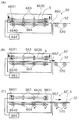
図1は、製造システムを示す断面図である。同図に示すように、製造システム100は2段構造となっており、1F(1階)部分はフィルム搬送機構50であり、2F(2階)部分は基板搬送機構(第1基板搬送機構および第2基板搬送機構)を含む貼合装置60となっている。
FIG. 1 is a cross-sectional view showing a manufacturing system. As shown in the figure, the
<フィルム搬送機構>
まず、フィルム搬送機構50について説明する。フィルム搬送機構50は、偏光フィルム(偏光板)を巻出してニップロール6・6aおよび16・16aまで搬送し、不要となった剥離フィルムを巻き取る役割を果たす。一方、貼合装置60はフィルム搬送機構50によって巻出された偏光フィルムを基板(液晶パネル)5に対して貼合する役割を果たすものである。
<Film transport mechanism>
First, the
フィルム搬送機構50は、第1フィルム搬送機構51および第2フィルム搬送機構52を備えている。第1フィルム搬送機構51は、基板5の下面に最初に偏光フィルムを貼合するニップロール6・6aに偏光フィルムを搬送するものである。一方、第2フィルム搬送機構52は、反転された基板5の下面に偏光フィルムを搬送するものである。
The
第1フィルム搬送機構51は、第1巻出部1、第2巻出部1a、第1巻取部2、第2巻取部2a、ハーフカッター3、ナイフエッジ4、および欠点フィルム巻取ローラー7・7aを備えている。第1巻出部1には偏光フィルムの原反が設置されており、偏光フィルムが巻出される。上記偏光フィルムとしては公知の偏光フィルムを用いればよい。具体的には、ポリビニルアルコールフィルムにヨウ素等によって染色がなされており、1軸方向に延伸されたフィルム等を用いることができる。上記偏光フィルムの厚さとしては、特に限定されないが、5μm以上、400μm以下の偏光フィルムを好ましく用いることができる。
The first
上記偏光フィルムの原反では、流れ方向(MD方向)に吸収軸の方向が位置している。上記偏光フィルムは剥離フィルムによって粘着剤層が保護されている。上記剥離フィルム(保護フィルムまたはセパレーターともいう)としては、ポリエステルフィルム、ポリエチレンテレフタラートフィルムなどを用いることができる。上記剥離フィルムの厚さとしては、特に限定されないが、5μm以上、100μm以下の剥離フィルムを好ましく用いることができる。 In the original film of the polarizing film, the direction of the absorption axis is located in the flow direction (MD direction). The polarizing film has a pressure-sensitive adhesive layer protected by a release film. As the release film (also referred to as a protective film or a separator), a polyester film, a polyethylene terephthalate film, or the like can be used. Although it does not specifically limit as thickness of the said peeling film, The peeling film of 5 micrometers or more and 100 micrometers or less can be used preferably.
製造システム100には、巻出部が2つ、巻出部に対応する巻取部が2つ備えられているため、第1巻出部1の原反の残量が少なくなった場合、第2巻出部1aに備えられた原反を第1巻出部1の原反に連結させることが可能である。その結果、偏光フィルムの巻出しを停止させることなく、作業を続行することが可能である。本構成により、生産効率を高めることができる。なお、上記巻出部および巻取部はそれぞれ複数備えられていればよく、3つ以上備えられていてももちろんよい。
Since the
ハーフカッター(切断部)3は、剥離フィルムに保護された偏光フィルム(偏光フィルム、粘着剤層および剥離フィルムから構成されるフィルム積層体)をハーフカットし、偏光フィルムおよび粘着剤層を切断する。ハーフカッター3としては、公知の部材を用いればよい。具体的には、刃物、レーザカッターなどを挙げることができる。ハーフカッター3によって偏光フィルムおよび粘着剤層が切断された後に、ナイフエッジ(除去部)4によって剥離フィルムが偏光フィルムから除去される。 The half cutter (cutting unit) 3 half-cuts the polarizing film (film laminate composed of the polarizing film, the pressure-sensitive adhesive layer and the peeling film) protected by the peeling film, and cuts the polarizing film and the pressure-sensitive adhesive layer. As the half cutter 3, a known member may be used. Specifically, a cutter, a laser cutter, etc. can be mentioned. After the polarizing film and the pressure-sensitive adhesive layer are cut by the half cutter 3, the release film is removed from the polarizing film by the knife edge (removal part) 4.
偏光フィルムと剥離フィルムとの間には粘着剤層が塗布されており、剥離フィルムが除去された後、粘着剤層は偏光フィルム側に残存する。上記粘着剤層としては、特に限定されるものではなく、アクリル系、エポキシ系、ポリウレタン系などの粘着剤層を挙げることができる。粘着剤層の厚さは特に制限されないが、通常5〜40μmである。 An adhesive layer is applied between the polarizing film and the release film, and after the release film is removed, the adhesive layer remains on the polarizing film side. The pressure-sensitive adhesive layer is not particularly limited, and examples thereof include acrylic, epoxy, and polyurethane pressure-sensitive adhesive layers. Although the thickness in particular of an adhesive layer is not restrict | limited, Usually, it is 5-40 micrometers.
一方、第2フィルム搬送機構52は、第1フィルム搬送機構51と同様の構成であり、第1巻出部11、第2巻出部11a、第1巻取部12、第2巻取部12a、ハーフカッター13、ナイフエッジ14および欠点フィルム巻取ローラー17・17aを備えている。同一の部材名を付した部材については第1フィルム搬送機構51における部材と同一の作用を示す。
On the other hand, the 2nd
好ましい形態として製造システム100は、洗浄部71を備えている。洗浄部71はニップロール6・6aによって基板5の下面に偏光フィルムを貼合する前に、基板5を洗浄するものである。洗浄部71としては、洗浄液を噴射するノズルおよびブラシなどから構成される公知の洗浄部を用いればよい。洗浄部71によって貼合の直前に基板5を洗浄することによって、基板5の付着異物が少ない状態にて貼合を行うことができる。
As a preferred embodiment, the
次に、図2を用いて、ナイフエッジ4について説明する。図2は、製造システム100におけるニップロール6・6aの周辺部分を示す断面図である。図2は、基板5が左方向から搬送され、左下方向から粘着剤層を有する(図示せず、以降同じ)偏光フィルム5aが搬送される状況を示している。偏光フィルム5aには剥離フィルム5bが備えられており、ハーフカッター3によって偏光フィルム5aおよび粘着剤層が切断され、剥離フィルム5bは切断されていない(ハーフカット)。
Next, the knife edge 4 will be described with reference to FIG. FIG. 2 is a cross-sectional view showing a peripheral portion of the nip rolls 6 and 6a in the
剥離フィルム5b側には、ナイフエッジ4が設置されている。ナイフエッジ4は、剥離フィルム5bを剥離させるためのエッジ状部材であり、偏光フィルム5aと接着力が低い剥離フィルム5bがナイフエッジ4を伝って剥離されることとなる。
A knife edge 4 is provided on the
その後、剥離フィルム5bは、図1の第1巻取部2に巻き取られることとなる。なお、ナイフエッジに代えて、粘着ローラーを用いて剥離フィルムを巻き取る構成を用いることも可能である。その場合、巻取部と同様に、粘着ローラーを2箇所に備えることによって、剥離フィルムの巻取効率を高めることができる。
Thereafter, the
<貼合装置>
次に、貼合装置60について説明する。貼合装置60は基板5を搬送し、フィルム搬送機構50によって搬送された偏光フィルムを基板に貼合するものである。図示しないが、貼合装置60では基板5の上面に対して、クリーンエアーが供給されている。すなわち、ダウンフローの整流が行われている。これによって、基板5の搬送および貼合を安定した状態にて行うことが可能である。
<Bonding device>
Next, the
貼合装置60はフィルム搬送機構50の上部に備えられている。これにより、製造システム100の省スペース化を図ることができる。図示しないが、貼合装置60にはコンベアーロールを備える基板搬送機構が設置されており、これにより基板5が搬送方向へ搬送される(図5にて後述する第1基板搬送機構61・第2基板搬送機構62が基板搬送機構に該当する)。
The
製造システム100では、左側から基板5が搬送され、その後、図中右側、つまり、第1フィルム搬送機構51の上部から第2フィルム搬送機構52の上部へと搬送される。フィルム搬送機構50と貼合装置60との間には、貼合部であるニップロール6・6a(第1貼合部)およびニップロール16・16a(第2貼合部)がそれぞれ備えられている。ニップロール6・6aおよび16・16aは、基板5の下面に剥離フィルムが除去された偏光フィルムを貼合わせる役割を果たす部材である。なお、基板5の両面には下面から偏光フィルムが貼合されるため、ニップロール6・6aにて貼合された後に、基板5は反転機構65によって反転される。反転機構65については後述する。
In the
ニップロール6・6aへ搬送された偏光フィルムは、粘着剤層を介して基板5の下面に貼合される。ニップロール6・6aとしては、それぞれ圧着ロール、加圧ロールなどの公知の構成を採用することができる。また、ニップロール6・6aにおける貼合時の圧力および温度は適宜調整すればよい。ニップロール16・16aの構成も同様である。なお、図示しないが、製造システム100では、好ましい構成として、第1巻出部1・11からハーフカッターまでの間に欠点表示(マーク)検出部が備えられており、欠点を有する偏光フィルムが検出される構成となっている。
The polarizing film conveyed to the nip rolls 6 and 6a is bonded to the lower surface of the
なお、上記欠点表示は、偏光フィルムの原反作成時に検出を行って欠点表示を付与する、または、欠点表示検出部よりも第1巻出部1および/または第1巻出部11側に備えられた欠点表示付与部によって偏光フィルムに付される。欠点表示付与部は、カメラ、画像処理装置および欠点表示形成部によって構成されている。まず、上記カメラによって偏光フィルムの撮影がなされ、当該撮影情報を処理することによって、欠点の有無を検査することができる。上記欠点としては、具体的には、埃などの異物、フィッシュアイなどが挙げられる。欠点が検出された場合、欠点表示形成部によって偏光フィルムに欠点表示が形成される。欠点表示としてはインクなどのマークが用いられる。
In addition, the said defect display is provided at the time of the 1st unwinding
さらに、図示しない貼合回避部は、上記マークをカメラにより判別して、貼合装置60に停止信号を送信して基板5の搬送を停止させる。その後、欠点が検出された偏光フィルムは、ニップロール6・6aによって貼合に用いられず、欠点フィルム巻取ローラー(回収部)7・7aにて巻き取られる。これにより、基板5と、欠点を有する偏光フィルムとの貼合わせを回避することができる。当該一連の構成が備えられていれば、欠点を有する偏光フィルムと基板5との貼合わせを回避できるため、歩留まりを高めることができ好ましい。欠点検出部および貼合回避部としては、公知の検査センサを適宜用いることができる。
Further, a bonding avoiding unit (not shown) discriminates the mark with a camera and transmits a stop signal to the
図1に示すように、反転機構65によって基板5が反転状態となった後、基板5はニップロール16・16aに搬送される。そして、基板5の下面に偏光フィルムが貼合される。その結果、基板5の両面に偏光フィルムが貼合わされることとなり、基板5の両面に2枚の偏光フィルムが互いに異なる吸収軸にて貼合された状態となる。その後、必要に応じて、貼りずれが生じていないか、基板5の両面について検査がなされる。当該検査は、通常、カメラを備える検査部等によってなされる構成を採用することができる。
As shown in FIG. 1, after the
このように製造システム100では、基板5へ偏光フィルムを貼合わせる際、基板5の下面から貼合を行う構成となっており、基板5への整流環境を妨げることがない。このため、基板5の貼合面への異物混入も防止することができ、より正確な貼合わせが可能となる。
Thus, in the
図3(a)および図3(b)に本発明と同様の下貼り型の製造システムにおける気流の速度ベクトルを示す。図3(a)・(b)における領域Aは巻出部が設置される領域であり、領域Bは主に偏光フィルムが通過する領域、および、領域Cは巻取部等が設置される領域である。また、HEPAフィルター40からはクリーンエアーが供給される。なお、図3(a)では、クリーンエアーが通過可能なグレーチング41が設置されているため、グレーチング41を介して、気流が垂直方向に移動することが可能である。一方、図3(b)では、グレーチング41が設置されていないため、気流は床に接触した後、床に沿って移動することとなる。
FIG. 3A and FIG. 3B show the velocity vector of the airflow in the under-paste type manufacturing system similar to the present invention. Regions A in FIGS. 3 (a) and 3 (b) are regions where the unwinding part is installed, region B is a region through which the polarizing film mainly passes, and region C is a region where the winding unit and the like are installed. It is. Further, clean air is supplied from the
図3(a)・(b)に示す製造システムは下貼り型であるため、図9(a)・(b)で示したように、偏光フィルムによってHEPAフィルター40からの気流が妨げられない。このため、気流ベクトルの方向はほとんど基板に向う方向となっており、クリーンルームにて好ましい整流環境が実現されているといえる。図3(a)では、グレーチング41が設置され、図3(b)では設置されていないが、両図とも同様の好ましい状態が示されている。なお、図3および図9では、基板搬送機構は水平に形成されているが、一連の構造としては設置されていない。このため、基板搬送機構間を気流が通過可能な構成となっている。基板は後述する反転機構によって保持された後、基板搬送機構間を移送される構成となっている。
Since the manufacturing system shown in FIGS. 3 (a) and 3 (b) is a bottom-attached type, the air current from the
また、製造システム100では、まず、基板5を長辺間口(長辺が搬送方向と直交する)にて搬送し、その後、短辺間口(短辺が搬送方向と直交する)にて搬送する構成となっている。
Moreover, in the
<基板支持装置>
基板支持装置66は、図4ないし図6に示されるように上記第1基板搬送機構61としてのコンベアーロール510を備える上記第1フィルム搬送機構51のフィルムおよび基板の搬送方向の下流端部および上記第2基板搬送機構61としてのコンベアーロール520を備える上記第2フィルム搬送機構52のフィルムおよび基板の搬送方向の上流端部に対して、ガタを考慮しても干渉しないように最小限の一定の間隙を隔てて、反転機構65の基板反転部67の反転動作に応じて基板支持部661が対向して配置されるように構成されている。
<Substrate support device>
As shown in FIGS. 4 to 6, the
上記基板支持装置66は、図4に示されるようにフィルムが貼合された基板より大きなサイズの矩形箱状部材によって構成され、2個の該矩形箱状部材が、180度の角度関係で一つのコーナー部が反転軸としての上記第1基板搬送機構61の搬送方向に対して45度の角度で配設された回転軸部68に対して、最も接近する態様で、反転機構65の基板反転部67の一端に機械的に結合され、連結されているものである。更にタクトタイムを短縮するために90度(60度)の角度関係で回転軸部68に対して4個(6個)の基板支持装置を配設することも可能である。
As shown in FIG. 4, the
すなわち一方の基板支持装置66が、図4に示されるように上記第1基板搬送機構61としてのコンベアーロール510を備える上記第1フィルム搬送機構51のフィルムおよび基板の搬送方向の下流端部に対向して配置されている時には、他方の基板支持装置66が、上記第2基板搬送機構61としてのコンベアーロール520を備える上記第2フィルム搬送機構52のフィルムおよび基板の搬送方向の上流端部に対して、対向するように配置されるように構成されている。
That is, one
上記基板支持装置66は、基板支持装置内に形成され、上記第1基板搬送機構61から搬送された上記基板5が搬送される搬送通路662と、該搬送通路662に搬送される上記基板5に接触して上記第1フィルム搬送機構51における基板の搬送方向に沿って搬送を行うように配設された搬送手段としての複数の搬送ロール663と、該搬送通路662から搬送される上記基板に接触して上記第2フィルム搬送機構52における基板の搬送方向に沿って搬送を行うように配設された搬送手段としての複数の搬送ロール664と、該複数の搬送ロール664を上下に移動させることにより、上記搬送通路662の基板支持位置に到達した上記基板を挟着して支持するとともに、後述する基板反転部67によって反転された上記基板の挟着状態を解除する基板支持駆動機構665とを備えている。
The
上記複数の搬送ロール663は、回転自在に支持された回転軸6630に対して一定間隔で複数の例えば4個のロール663が配設され、該回転軸6630を一定間隔で複数の例えば3個並設されており、モータその他の回転駆動装置によって、必要に応じて回転連絡手段を介して上記第1の基板搬送機構61と同期して回転駆動されるように構成されている。回転駆動装置は、上記第1および第2の基板搬送機構用の回転駆動装置を流用して回転連絡手段を介して上記第1の基板搬送機構と同期して回転駆動しても良く、上記第1の基板搬送機構用の回転駆動装置とは別個の回転駆動装置を用いて同一または同様の駆動指令によって、必要に応じて回転連絡手段を介して上記第1の基板搬送機構と同期して回転駆動してもよい。
The plurality of transport rolls 663 are provided with a plurality of, for example, four
上記複数の搬送ロール664は、回転自在に支持された回転軸6640に対して一定間隔で複数の例えば3個のロール664が配設され、該回転軸6640を一定間隔で複数の例えば4個並設されており、モータその他の回転駆動装置によって、必要に応じて回転連絡手段を介して上記第2の基板搬送機構62と同期して回転駆動されるように構成されている。
The plurality of transport rolls 664 are provided with a plurality of, for example, three
上記回転駆動装置は、上記第2の基板搬送機構用の回転駆動装置を流用して回転連絡手段を介して上記第2の基板搬送機構と同期して回転駆動しても良く、上記第2の基板搬送機構用の回転駆動装置とは別個の回転駆動装置を用いて同一または同様の駆動指令によって、必要に応じて回転連絡手段を介して上記第2の基板搬送機構と同期して回転駆動してもよい。 The rotation drive device may be driven to rotate in synchronization with the second substrate transfer mechanism via a rotation communication unit by using the rotation drive device for the second substrate transfer mechanism. Using a rotation drive device that is separate from the rotation drive device for the substrate transport mechanism, the same or similar drive command is used to rotate and synchronize with the second substrate transport mechanism via the rotation communication means as necessary. May be.
上記支持駆動機構665は、上記複数の搬送ロール664が複数配設された回転軸6640の両端を軸支する支持部6641を、例えば該支持部6641に機械的に連結したラックとモータによって回転駆動されるピニオンとから成るラックアンドピニオン機構によって、基板支持指令および基板解除指令に基づき上下に移動させることにより、互いに直交関係に複数配設された複数の第1および第2の搬送ローラ663、664によって、図5(C)に示される上記搬送通路662の基板支持位置に到達した上記基板を挟着して支持するとともに、反転した上記基板の挟着状態を解除することを可能にするものである。
The
上記基板支持駆動機構665は、上記複数の搬送ロール664が複数配設された回転軸を、下方に移動させて上記基板5を挟着して反転後に上方に移動させる例について説明したが、図5における複数の搬送ロール663を上方に移動させて上記基板5を挟着して反転後図6における上記複数の搬送ロール663および複数の搬送ロール664をともに上方に移動させて上記基板5の挟着を解除する態様や、複数の搬送ロール663および上記複数の搬送ロール664の両者を上下に移動させる態様も、複数の搬送ロール663および上記複数の搬送ロール664を相対的に接近するものであるので、採用可能である。
The substrate
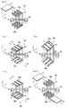
また上記基板支持駆動機構665は、上述においては、上記複数の搬送ロール664が複数配設された回転軸6640を上下に移動させることにより、上記搬送通路662の基板支持位置に到達した上記基板を挟着して支持するとともに、反転した上記基板の挟着状態を解除するようにして、互いに直交する上記複数の搬送ロール663および664によって、基板を支持する基板支持部材を構成する例について説明したが、上記複数の搬送ロール663および664とは別に1個または複数の基板支持部材を上記基板支持装置66内に配設して、例えば図7(A)に示されるように基板支持部材6651を上述と同様に下方に移動させることにより、または基板支持部材6651Dを上方に移動させることにより、上記複数の搬送ロール663または664の一方に対して相対的に接近させることにより、上記基板支持位置に到達した上記基板5を挟着して支持するように構成することも可能である。
Further, in the above description, the substrate
さらに図7(B)に示されるように2個の基板支持部材6652、6653の少なくとも一方を上述と同様に下方または上方に移動させることにより、相対的に接近させることにより、上記基板支持位置に到達した上記基板を2個の基板支持部材6652、6653によって挟着して支持するように構成することも可能である。
Further, as shown in FIG. 7B, by moving at least one of the two
上記基板支持駆動機構665は、上記1個または複数の基板支持部材6651ないし6653が、電気的駆動装置の駆動力によって、相対的に接近することにより、上記基板支持位置に到達した上記基板を挟着して支持するように構成することが可能であるが、図8(A)に示されるように基板支持部材6651ないし6653と一体的に形成された一端がソレノイド6654内に介挿された突出部材を、電気的入力に基づき磁気的に吸引することにより、基板支持部材6651ないし6653を図中上方に移動させることにより、反転させる基板5を支持することが可能であり、また図8(B)に示されるように基板支持部材6651ないし6653と一体的に形成された中央部の一端がソレノイド6654内に介挿された縦断面形状略E字状の突出部材を、電気的入力に基づき磁気的に吸引することにより、基板支持部材6651ないし6653を図中下方に移動させることにより、反転させる基板5を支持することが可能である。
The substrate
また基板支持駆動機構665は、上記1個または複数の基板支持部材6651ないし6653が、機械的駆動装置の駆動力によって、相対的に接近することにより、上記基板支持位置に到達した上記基板5を挟着して支持するように構成することが可能であるが、図8(C)に示されるようにバネ部材によって下方に付勢されている基板支持部材6651ないし6653を、バネ部材6662による下方への付勢力に抗して楔状部材6661が介挿されることにより、基板支持部材6651ないし6653と上記搬送通路662との間に一定の間隙が形成されており、フィルムが貼合された上記基板が上記搬送通路662に配送され、上記基板支持位置に到達すると、フィルムが貼合された上記基板の移動に応ずる揺動部材(図示せず)の揺動により上記楔状部材6661が図中右方に後退するため、上記基板支持部材6651ないし6653がバネ部材6662の付勢力によって下方に移動して、上記基板支持位置に到達したフィルムが貼合された上記基板を搬送ロール663との間に挟着するように構成され、基板支持装置が基板反転部67の反転によって反転すると、後退していた上記楔状部材6661が再び図中左方に侵入して、上記基板支持部材6651ないし6653をバネ部材の付勢力に抗して上方に移動させることにより、反転した上記基板の挟着を解除して、第2基板搬送機構62への上記基板の搬送を可能にするものであり、電気的駆動装置を利用する場合に比べて制御および制御装置が不要になるという利点を有する。
Further, the substrate
上記楔状部材6661は、反転された基板5を基板支持装置66内から第2基板搬送機構62への搬送経路に対しては、オフセットして配設されており、 基板の搬送の障害にはならないように構成されている。
The wedge-shaped member 6661 is disposed so as to be offset with respect to the transport path from the inside of the
さらに基板支持駆動機構665は、上記1個または複数の基板支持部材6651ないし6653が、駆動装置から供給される流体圧の作用により、吸着、圧着または挟着することによって、上記基板支持位置に到達した上記基板を挟着して支持するように構成することが可能であるが、図8(D)に示されるように上記1個または複数の基板支持部材6651ないし6653に対して連結部材6656を介して連結するピストン6657が介挿されたシリンダ6658の左右の部屋へのポンプからの2方向切替弁6659を介してエアー、水、油圧その他の流体の供給または排出によるシリンダ6658内ピストン6657の上下動に応じて、上記基板支持部材6651ないし6653を上方または下方に移動して、上記基板支持位置に到達したフィルムが貼合された上記基板を搬送ロール663との間に挟着するとともに、挟着状態を解除することが可能である。
Further, the substrate
また支持駆動機構665は、上記基板支持部材によって挟着することなく、エアーその他の流体による負圧による上記基板支持部材としての吸着部への吸着またはエアーその他の流体による押圧力によって上記基板支持部材としての押圧部への押圧によって基板を支持するようにすることも可能であり、圧力源を工場内の適宜箇所に配置して、上記回転軸部68および基板反転部67を介して流体の供給を可能にすれば、上記基板支持装置内に上記吸着部または押圧部を上記基板支持部材に形成するただけでよいため、上記基板支持装置の構成をシンプルにして、上記基板支持装置の軽量化を可能にするとともに、上記基板支持装置の高速回転およびタクトタイムの短縮を可能にするものである。
Further, the
上記基板支持部材のその他の態様について、以下説明する。
基板支持部66aは、基板5を支持する部材であり、載置した基板を挟持可能である。また、基板支持部66aは基板5を吸着する吸着手段を好ましい形態として備えている。吸着手段としては、公知のものを用いることができ、例えば、空気吸引方式の吸着手段を用いることができる。図9では、基板支持部66aはパイプ状のアームおよび吸着手段から構成されており、吸着手段にて吸引された空気がアーム中を通過する構成となっているが、アームおよび吸着手段の形状は当該構成に限定されるものではない。
Other aspects of the substrate support member will be described below.
The
また、基板支持部66aはアームに吸着手段が2つ備えられた構造となっており、3本のアームからなるアーム群を1対備えている。また、吸着手段は基板5の対角線上に4つ配置されており、基板5の長さ方向において、上記吸着手段間にさらに吸着手段が2つ配置されている。当該アームの本数および吸着手段の設置数はあくまで一例であり、例えば、大きな基板を反転させる場合には、アームの本数および吸着手段の数を増加させるなど適宜変更すればよい。また、吸着手段の設置場所を基板5の中心部分に集中させる、または、基板5の端部周辺に変更するなどの変更ももちろん可能である。
Further, the
基板反転部66aが基板5を載置していない場合、基板5を受け入れ可能なようにアーム群間の距離が広がった状態となっている(以下、この状態を「待機状態」と称する)。一方、基盤反転部66bは基板5もアーム群間の距離が広がった状態となっている。また、1対のアーム群は基板5を挟持するため、アーム群間の距離を狭めることもできる。このようにアーム群間の距離は変更可能であり、そのために基板支持部66a・66bは、モーターを有しており、モーターの回転運動を直線運動に変えてアーム群間の距離を変更する構成となっている。なお、アーム群間の距離を変更できる構成であれば、モーターを備える構成に変えて用いてもよい。
When the
<反転機構>
反転機構65は、短辺または長辺が搬送方向に沿った基板5を、長辺または短辺が第2基板搬送機構の搬送方向に沿った状態に反転させるものである。つまり、基板5の表面と裏面とを反転させ、搬送方向に沿った基板5の長辺および短辺を入れ替えるものである。まず、図9を用いて反転機構65の構造について説明する。
<Reversing mechanism>
The reversing
図9は、反転機構65を示す斜視図であり、基板5を反転させる過程における反転機構65の動作を示している。反転機構65は、上記基板支持部66a・66bが一端に連結して配設されいる基板反転部67および回転軸部68を備えている。以下各部材について説明する。
FIG. 9 is a perspective view showing the reversing
基板反転部67は、一端が上記基板支持部66a・66bに連結されており、反転軸Mを中心として回転することによって基板5を反転させるものである。図9において基板反転部67はそれぞれのアームに連結されており、軽量化および回転時の空気抵抗を軽減する観点から好ましい構造としてパイプ状の構造となっている。しかしながら、当該構造に限定されるものではない。例えば、パイプ状に代えて板状であってもよい。
One end of the
基板反転部67は、反転軸Mを中心として回転するものである。基板反転部67を回転させる部材としてはモーターによる駆動手段が挙げられる。図9(a)において、好ましい形態として基板反転部67は回転軸部68を備えている。回転軸部68は反転軸Mに沿って配置されているため、反転軸Mに沿って安定して回転可能である。本実施の形態では、基板反転部67は回転軸部68と共に回転する構造となっており、反転軸Mを中心として基板反転部67が安定して回転し易い構造となっている。このため、回転軸部68を備える基板反転部67は反転軸Mに沿ってより安定して回転可能である。したがって、基板5の反転をより安定して行うことが可能となる。なお、回転軸部68は反転前の基板5に対して表面方向に向かって回転することも、逆に裏面方向に向かって回転することも可能である。
The
反転軸Mは、図9(a)に示すように「第1基板搬送機構における反転前の基板5の中心を通り、上記基板5の搬送方向D1と垂直な直線に対して45°の傾きを有する直線を含み、第1基板搬送機構における反転前の基板5を含む面内」に位置している。上記45°の傾きを有する直線は、図9(a)の反転軸Mに沿った直線である。また、「第1基板搬送機構における反転前の基板5を含む面」とは反転前の基板5と同一平面を意味し、図9(a)ではX‐Y面に位置する面をいう。
As shown in FIG. 9A, the reversal axis M has an inclination of 45 ° with respect to a straight line passing through the center of the
図9では、基板支持部66a・66bと、基板反転部67および回転軸部68が別個に構成され、一体的に連結された例について説明したが、各部材の機能を有していれば一体の部材として構成されていてももちろんよい。
In FIG. 9, the
次に、反転機構65の動作について説明する。図9では、第1基板搬送機構の搬送方向D1に基板5の短辺が沿っており、第2基板搬送機構の搬送方向D2に基板5の長辺が沿った状態となるように基板5を反転させる場合について説明する。しかしながら、搬送方向D1に基板5の長辺が沿っており、搬送方向D2に基板5の短辺が沿った状態に反転することも同様に可能である。
Next, the operation of the reversing
図9(w1)は待機状態の反転機構65を示す斜視図である。同図に示すように、基板支持部66aは基板5を受け入れられるように1対のアーム群間の距離が広がった状態となっている。一方、基板支持部66bは基板5が反転される位置に配置されており、反転させた基板5を解放するため、基板支持部66bが備える1対のアーム群間の距離も広がった状態となっている。
FIG. 9 (w1) is a perspective view showing the reversing
X‐Y平面における搬送方向D1に沿って基板支持部66aへ基板5が搬送されると、基板支持部66aに基板5が載置される。具体的には、アーム群間に基板5が移動し、基板支持部66aの下方のアーム群上に基板5が載置される。アーム群上に基板5が載置されたか否かは、基板確認センサーによって判断される。本実施形態において、基板確認センサーは基板支持部66aおよび基板支持部66bのそれぞれに備えられた構成となっているが、基板5の載置を確認できる位置に備えられていればよく、当該位置以外に備えられていてもよい。
When the
その後、基板確認センサーから基板5の確認信号がアーム群に送信されると、図9(a)に示すように、アーム群同士が近付いて基板5が挟持される。さらに、吸着手段によって基板5の表面が吸着されて基板5がより固定される。このように吸着手段による吸着によって、アーム群だけで基板5を挟持する場合よりも、さらに基板5を固定することができる。これによって、基板5が回転時に脱着することを回避できる。
Thereafter, when a confirmation signal of the
次に、回転軸部68が反転軸Mを中心に回転することによって、共に基板反転部67も基板5の表面方向に回転する。図9(b)は図9(a)の状態から基板反転部67が反転軸Mを中心として90°回転した状態を示している。図9(b)では基板5はZ軸方向に沿って位置している。このとき、基板支持部66bは、基板5を挟持しておらず、基板反転部67の回転に伴って下方に90°回転されている。
Next, when the
さらに、回転軸部68と共に基板反転部67が反転軸Mを中心として90°回転することによって、反転軸Mに対して線対称の位置に基板5が反転される。なお、図示しないが、搬送方向D2側の基板5の端部は第2基板搬送機構のコンベアーロールに位置している。当該状態を図9(c)に示す。このように、図9(a)〜(c)に示すように、基板5の長辺および短辺が基板の搬送方向に沿って反対となると共に、基板の表面および裏面の反転がなされている。このため、ニップロール16・16aによって下面から偏光フィルムをその吸収軸が直交するように貼合することができる。また、反転機構65の動作は反転軸Mを中心とした180°の半円軌道を描くものであり、複雑な動作を必要としない。したがって、短いタクトタイムにて1枚の基板5を反転させることができる。
Further, the
さらに、基板支持部66a・66bは反転軸Mに対して線対称に一対備えられている。このため、基板支持部66aによって基板5が反転されると、他方の基板支持部66bは図9(a)での反転前の基板5のあった位置に移動される。
図9(c)の状態から基板支持部66aの吸着手段による吸着が解除され、アーム群間の距離が広げられると基板5は一対のアーム群のうち、下方のアーム群上に載置される。その後、図9(w2)に示すように、第2基板搬送機構が備えるコンベアーロールの回転に伴って基板5は搬送方向D2へ搬送される。
Further, a pair of
When the suction by the suction means of the
ここで、基板支持部66bは反転前の基板5の位置に移動している。これにより、基板支持部66aの移動を待つことなく、次に搬送される基板5' を速やかに反転させることができる。つまり、貼合装置60によれば1枚の基板の反転はもちろん、基板を反転させた後に、次の基板を載置するまでに時間を短縮することができる。その結果、複数の基板を短いタクトタイムにて順次処理することができる。
Here, the board |
図10(a)〜(c)は、図9(a)〜(c)に対応する基板5の回転過程を示す平面図である。図10では、基板の搬送方向に対して直角な方向にオフセットした第1基板搬送機構61および第2基板搬送機構62を図示している。第1基板搬送機構61および第2基板搬送機構62には図示しないが、基板5を搬送する複数のコンベアーロールが、基板5の搬送方向に対して直交して備えられている。なお、基板5の搬送する手段はコンベアーロールに限定されるものではなく、他の代替手段を用いてもよい。
FIGS. 10A to 10C are plan views showing the rotation process of the
第1基板搬送機構61および第2基板搬送機構62は、基板5を同一方向に搬送するものである。すなわち、搬送方向D1・D2は同一方向に向かっている。このため、第1基板搬送機構61および第2基板搬送機構62は、搬送方向D1・D2にそれぞれ沿った直線状の形状となっている。すなわち、L字型形状などの複雑な構造を有していない。したがって、本実施形態に係る貼合装置60は、設置が非常に簡便であり、面積効率に優れる構造となっている。
The first
まず、図9(w1)にて説明したように、基板5が搬送方向D1に沿って搬送され、第1基板搬送機構61の端部からコンベアーロールの回転力によって基板支持部66aに載置される。そして、載置された基板5が基板支持部66aの一対のアーム群によって挟持された後、吸着手段によって基板の表面が吸着されて固定される。当該反転機構65の状態を図10(a)に示す。
First, as described in FIG. 9 (w1), the
その後、回転軸部68が基板5の表面方向へ反転軸Mを中心として90°回転すると共に、基板反転部67も回転する。図10(b)は図10(a)から基板反転部67が反転軸Mを中心として90°回転した状態を示している。このとき、基板支持部66bは、基板5を挟持していないが基板反転部67の回転に伴って下方に90°回転されている。さらに、回転軸部68と共に反転軸Mを中心として基板反転部67が90°回転することによって基板5が反転される。基板5が反転されたときの反転機構65の状態を図10(c)に示す。基板5は反転軸Mに対して線対称の位置に反転されている。
Thereafter, the
図10(c)では、基板5の端部が第2基板搬送機構62に位置している。図9(c)について説明したように、その後、基板5の吸着が解除され、アーム群間の距離が広げられる。その後、基板5は一対のアーム群のうち、下方のアーム群上に載置される。さらに第2基板搬送機構が備えるコンベアーロールの回転に伴って基板5へ搬送されることとなる。その後、基板支持部66bによって基板5が反転される。このように、基板支持部66a・66bによって順次搬送される基板が効率良く反転される。
In FIG. 10C, the end portion of the
なお、図9および図10では、基板支持部66a・66bが吸着手段を備える構成としているが、アーム群のみによって基板5を固定する構成であってもよい。その場合、吸着手段によって基板5を吸着および脱着する動作が不要となる。
9 and 10, the
反転機構65の構成例を図11に示す。図11は反転機構65および反転機構65に連結されたインターフェイス部165の構成を示すブロック図である。図11に示す構成はあくまで一例であって反転機構65はこの一例に限定されるものではない。図11に示すように、さらに、反転機構65は、インターフェイス部165に接続されている。インターフェイス部165は、オペレーターからの操作入力を受け付け、入力データを表示および反転機構65へと送信するものである。
A configuration example of the reversing
反転機構65では、基板支持部66a・66b、基板反転部67および回転軸部68が備えられており、これらはインターフェイス部における制御部70に接続されている。一方、インターフェイス部165は、入力部166、表示部167、記憶部168および制御部70を備えている。入力部166は、基板5の情報等を記憶部168に送信するものである。基板5の各情報としては、基板5の長辺および短辺の長さ、厚さ、搬送速度、単位時間当たりの搬送枚数が挙げられる。その他の情報としては、第1基板搬送機構61および第2基板搬送機構62の位置およびこれらが備えるコンベアーロールの位置、搬送方向D1・D2、反転軸Mの位置、基板5の回転速度、などが挙げられる。
The reversing
また、インターフェイス部165は、図示しない入力装置を備えている。上記入力装置はオペレーターが各種情報を入力できるものであればよく、例えば、入力キーやタッチパネルで構成することができる。表示部167は、入力部166によって入力された各種情報の内容を表示するものであり、公知の液晶ディスプレイ等で構成することができる。
The
記憶部168は、制御部70および入力部166に接続されている。記憶部168は、入力部から入力された情報を記憶するものであり、例えば、例えばRAM(random access memory)、HDD(ハードディスクドライブ)などの記憶装置を備えて、各種データおよび各種プログラムを記憶するものである。
The
制御部70は、記憶部168から受信した情報に基づき基板支持部66a・66b、これらが備える吸着手段、基板反転部67および回転軸部68を制御する。制御部70には、基板5の回転を制御する回転情報が記憶されている。基板5の回転を制御する回転情報とは、反転機構65を制御する回転情報であり、(1)基板5が基板支持部66a(または66b)に到着し、(2)センサーが基板5を感知し(センサーON)、(3)基板支持部66aのアーム群によって基板5が挟持され、(4)基板5が反転され、(5)基板5が解放された後に基板反転部67を反転させるという反転機構65の一連の動作を制御する情報(またはプログラム)である。
Based on the information received from the
当該構成によれば、例えば、基板5の搬送速度(または、搬送方向D1・D2、反転軸Mの位置、基板5の回転速度)の変更情報を入力部166から記憶部168へ送信し、容易に反転機構65の動作に反映させることが可能である。制御部70は、CPU(central processing unit )、上記プログラムを記憶したROM(read only memory)、上記プログラムを展開するRAM、上記プログラムおよび各種データを記憶するメモリ等の記憶装置(記録媒体)などを備えた構成とすることができる。
According to this configuration, for example, change information on the conveyance speed of the substrate 5 (or the conveyance direction D1, D2, the position of the reversing axis M, the rotation speed of the substrate 5) is transmitted from the
上記構成より成る本実施形態の基板搬送機構における搬送手段を備えた基板支持装置は、上記基板支持装置66の上記搬送手段663、664によって、長方形の基板5を長辺または短辺が搬送方向に沿った状態にて搬送する上記第1基板搬送機構61から搬送された上記基板5が、基板支持装置内の搬送通路662において搬送されるとともに、少なくとも1個の上記基板支持部材によって搬送され基板支持位置に到達した上記基板5が支持されるものであるので、上記第1基板搬送機構61において搬送された上記基板5を、上記第1基板搬送機構61から基板支持装置66内の搬送通路662を介して上記基板支持位置まで確実かつ滑らかに搬送することが可能であり、少なくとも1個の上記基板支持部材663、664、6651ないし6653によって、基板支持位置に到達した上記基板が確実に支持されるとともに、少なくとも1個の上記基板支持部材に連結した上記基板反転部67によって、上記基板5を上記基板を短辺または長辺が搬送方向に沿った状態にて搬送する第2基板搬送機構62への反転動作を可能にするという効果を奏する。
The substrate supporting apparatus provided with the conveying means in the substrate conveying mechanism of the present embodiment having the above-described configuration is configured such that the long side or the short side of the
また本実施形態の基板搬送機構における搬送手段を備えた基板支持装置は、上記搬送手段の上記第1の搬送手段663によって、上記第1基板搬送機構61において搬送された上記基板5を、上記基板支持装置66内の搬送通路662において上記第1基板搬送機構61に沿った方向にて上記基板5を搬送するものであり、基板支持位置に到達した上記基板5が、少なくとも1個の基板支持部材の一方66a、66bによって確実に支持されるととも、上記第2基板搬送機構62に沿った方向にて上記基板5を搬送する第2の搬送手段664によって、上記基板支持装置66内の搬送通路662において上記基板反転部67によって反転された上記基板5を上記第2基板搬送機構62に沿った方向にて搬送することにより、上記基板支持装置66内から反転された上記基板5を上記第2基板搬送機構62へ確実かつ滑らかに搬送することを可能にするという効果を奏する。
Further, the substrate support apparatus provided with the transfer means in the substrate transfer mechanism of the present embodiment is configured such that the
さらに本実施形態の基板搬送機構における搬送手段を備えた基板支持装置は、上記2個の基板支持部材663、664、6652、6653が、上記基板5が上記基板支持位置に到達すると、相対的に接近することにより上記基板5を挟着して支持するので、上記2個の基板支持部材による相対的な接近によって上記基板の両面を挟着することにより、上記基板支持位置に到達した上記基板5を確実に支持するという効果を奏する。
Furthermore, the substrate support apparatus provided with the transport means in the substrate transport mechanism of the present embodiment is such that the two
また本実施形態の基板搬送機構における搬送手段を備えた基板支持装置は、上記第1および第2の搬送手段を構成する互いに直交関係に複数配設され、上記駆動装置によって上記第1および第2の基板搬送機構61、62と同期して回転駆動された上記第1および第2の搬送ローラ663、664によって、上記基板支持装置66内の搬送通路662において上記第1基板搬送機構61に沿った方向にて上記基板5を同期して搬送するとともに、上記基板支持装置66内の搬送通路において上記第2基板搬送機構62に沿った方向にて上記基板を同期して搬送することが出来るので、上記第1基板搬送機構61から搬送された上記基板5に対して回転差による不要な力を作用させること無く、上記基板支持装置66内の搬送通路662において滑らかに搬送されるとともに、上記基板支持装置66内の搬送通路662から搬送された上記基板5に対して回転差による不要な力を作用させること無く、上記第2基板搬送機構62において滑らかに且つ基板5および偏向フィルムの変形および破損を発生させること無く搬送されるという効果を奏する。
Further, a plurality of substrate supporting devices provided with the conveying means in the substrate conveying mechanism of the present embodiment are arranged in an orthogonal relationship to constitute the first and second conveying means, and the first and second are driven by the driving device. The first and
さらに本実施形態の基板搬送機構における搬送手段を備えた基板支持装置は、上記第1または第2の搬送ローラ663、664の少なくともいずか一方が相対的に接近することにより、上記基板支持位置に到達した上記基板5を挟着して支持するように構成され、上記基板支持部材としても機能するので、上記第1または第2の搬送ローラ663、664とは別に上記基板支持部材を設けることを不要にするので、構成をシンプルして、軽量化を可能にするという効果を奏する。
Furthermore, the substrate support apparatus provided with the transfer means in the substrate transfer mechanism of the present embodiment has the substrate support position when at least one of the first or
また本実施形態の基板搬送機構における搬送手段を備えた基板支持装置は、上記第1または第2の搬送ローラ663、664の一方に対して、上記基板支持部材6651、が相対的に接近することにより、上記基板支持位置に到達した上記基板を挟着して支持するものであるので、上記基板を挟着するための上記第1または第2の搬送ローラの相対的な接近を不要にして、上記第1または第2の搬送ローラを含む搬送手段の構成をシンプルにして信頼性を高めることが出来るという効果を奏する。
Further, in the substrate supporting apparatus provided with the conveying means in the substrate conveying mechanism of the present embodiment, the
さらに本実施形態の基板搬送機構における搬送手段を備えた基板支持装置は、上記少なくとも1個の基板支持部材6651、6652、6653が、電気的駆動装置の駆動力によって、相対的に接近することにより、上記基板支持位置に到達した上記基板を挟着して支持するものであるので、駆動指令に基づく電気的駆動装置の駆動力によって、上記基板を挟着して支持する制御を容易に実現するとともに、制御ロジックまたは制御プログラムに応じて高度で複雑な制御も可能にするという効果を奏する。
Furthermore, the substrate supporting apparatus provided with the conveying means in the substrate conveying mechanism of the present embodiment is such that the at least one
また本実施形態の基板搬送機構における搬送手段を備えた基板支持装置は、上記少なくとも1個の基板支持部材6651、6652、6653が、機械的駆動装置の駆動力によって、相対的に接近することにより、上記基板支持位置に到達した上記基板5を挟着して支持するものであるので、複雑な制御をすることなく機械的駆動装置の駆動力に基づき機械的な機構によって、上記基板を挟着して支持を容易かつ確実に実現するという効果を奏する。
Further, the substrate support apparatus provided with the transfer means in the substrate transfer mechanism of the present embodiment is such that the at least one
さらに本実施形態の基板搬送機構における搬送手段を備えた基板支持装置は、上記少なくとも1個の基板支持部材6651、6652、6653が、駆動装置から供給される流体圧の作用により、吸着、圧着または挟着することによって、上記基板支持位置に到達した上記基板5を挟着して支持するものであるので、流体圧を供給する駆動装置を上記基板支持部材とは別の適宜部位に配置することにより、上記基板支持部材の構成をシンプルにして、軽量化、高速回転、製造ラインのタクトタイムの短縮を可能にするという効果を奏する。
Further, in the substrate support apparatus provided with the transport means in the substrate transport mechanism of the present embodiment, the at least one
また本実施形態の偏光フィルムの貼合装置における搬送手段を備えた基板支持装置は、上記基板支持装置の上記搬送手段によって、長方形の基板を長辺または短辺が搬送方向に沿った状態にて搬送する上記第1基板搬送機構から搬送され第1の偏光フィルムが貼合された上記基板が、基板支持装置内の搬送通路において搬送されるとともに、少なくとも1個の上記基板支持部材によって搬送され基板支持位置に到達した第1の偏光フィルムが貼合された上記基板が支持されるものであるので、上記第1基板搬送機構において搬送された第1の偏光フィルムが貼合された上記基板を、上記第1基板搬送機構から基板支持装置内の搬送通路を介して上記基板支持位置まで確実かつ滑らかに搬送することが可能であり、少なくとも1個の上記基板支持部材によって、基板支持位置に到達した第1の偏光フィルムが貼合された上記基板が確実に支持されるとともに、少なくとも1個の上記基板支持部材に連結した上記基板反転部によって、第1の偏光フィルムが上記基板を上記基板を短辺または長辺が搬送方向に沿った状態にて搬送する第2基板搬送機構への上記基板反転部の反転動作および上記第2貼合部による第2の偏光フィルムの貼合を可能にするという効果を奏する。 Moreover, the board | substrate support apparatus provided with the conveyance means in the bonding apparatus of the polarizing film of this embodiment is a state in which the long side or the short side was along the conveyance direction by the said conveyance means of the said board | substrate support apparatus. The substrate transported from the first substrate transport mechanism to be transported and bonded with the first polarizing film is transported in a transport path in the substrate support device and transported by at least one of the substrate support members. Since the substrate on which the first polarizing film that has reached the support position is bonded is supported, the substrate on which the first polarizing film transferred in the first substrate transfer mechanism is bonded, It is possible to reliably and smoothly transport from the first substrate transport mechanism to the substrate support position through a transport path in the substrate support apparatus, and at least one of the substrate supports. The member securely supports the substrate on which the first polarizing film that has reached the substrate support position is bonded, and the first polarization unit by the substrate inversion unit connected to at least one of the substrate support members. Reversing operation of the substrate reversing unit to the second substrate transporting mechanism for transporting the substrate with the substrate in a state where the short side or the long side of the substrate is along the transporting direction, and the second polarization by the second bonding unit There is an effect that the film can be bonded.
さらに本実施形態の偏光フィルムの貼合装置における搬送手段を備えた基板支持装置は、上記基板支持装置の上記搬送手段によって、長方形の基板を長辺または短辺が搬送方向に沿った状態にて搬送する上記第1基板搬送機構から搬送され第1の偏光フィルムが貼合された上記基板が、基板支持装置内の搬送通路において搬送されるとともに、少なくとも1個の上記基板支持部材によって搬送され基板支持位置に到達した第1の偏光フィルムが貼合された上記基板が支持されるものであるので、上記第1基板搬送機構において搬送された第1の偏光フィルムが貼合された上記基板を、上記第1基板搬送機構から基板支持装置内の搬送通路を介して上記基板支持位置まで確実かつ滑らかに搬送することが可能であり、少なくとも1個の上記基板支持部材によって、基板支持位置に到達した第1の偏光フィルムが貼合された上記基板が確実に支持されるとともに、少なくとも1個の上記基板支持部材に連結した上記基板反転部によって、第1の偏光フィルムが上記基板を上記基板を短辺または長辺が搬送方向に沿った状態にて搬送する第2基板搬送機構への上記反転機構の上記基板反転部の反転動作および上記第2貼合部による第2の偏光フィルムの貼合を可能にするという効果を奏する。 Furthermore, the board | substrate support apparatus provided with the conveyance means in the bonding apparatus of the polarizing film of this embodiment is a state in which the long side or the short side followed the conveyance direction by the said conveyance means of the said board | substrate support apparatus. The substrate transported from the first substrate transport mechanism to be transported and bonded with the first polarizing film is transported in a transport path in the substrate support device and transported by at least one of the substrate support members. Since the substrate on which the first polarizing film that has reached the support position is bonded is supported, the substrate on which the first polarizing film transferred in the first substrate transfer mechanism is bonded, It is possible to reliably and smoothly transport from the first substrate transport mechanism to the substrate support position via a transport path in the substrate support apparatus, and at least one of the substrates The holding member securely supports the substrate on which the first polarizing film that has reached the substrate support position is bonded, and the substrate reversing unit connected to at least one of the substrate support members provides the first The reversing operation of the substrate reversing portion of the reversing mechanism and the second bonding portion to the second substrate transporting mechanism, in which the polarizing film transports the substrate with the short side or the long side along the transport direction. There exists an effect of enabling bonding of the 2nd polarizing film by.
また本実施形態の偏光フィルムの貼合装置における搬送手段を備えた基板支持装置は、上記偏光フィルムの貼合装置を含み、上記反転機構が備える上記基板反転部67が、上記基板の搬送方向に対して一定の傾きで配設された反転軸回りに回転して反転動作するものであるので、上記基板の搬送方向に対して一定の傾きで配設された反転軸回りに回転する上記基板反転部の一の反転動作により、第1の偏光フィルムが貼合された上記基板の搬送方向に沿った短辺および長辺の方向を変更することが出来るとともに、製造ラインのタクトタイムを短くすることが出来るという効果を奏する。
Moreover, the board | substrate support apparatus provided with the conveyance means in the bonding apparatus of the polarizing film of this embodiment contains the said polarizing film bonding apparatus, and the said board |
さらに本実施形態の貼合装置における搬送手段を備えた基板支持装置は、上記偏光フィルムの貼合装置が含む上記反転機構が備える上記基板反転部67が、上記基板5の搬送方向に対して45°の傾きで配設された反転軸回りに回転して反転動作するものであるので、上記基板5の搬送方向に対して45°の傾きで配設された反転軸回りに回転する上記基板反転部67の一の反転動作により、第1の偏光フィルムが貼合された上記基板5の搬送方向に沿った短辺および長辺の方向を変更することが出来るとともに、製造ラインのタクトタイムを短くすることが出来るという効果を奏する。
Furthermore, the board | substrate support apparatus provided with the conveyance means in the bonding apparatus of this embodiment WHEREIN: The said board |
<その他の付帯的構成>
さらに、好ましい形態として、製造システム100は、制御部70、洗浄部71、貼りずれ検査装置72および貼合異物自動検査装置73および仕分け搬送装置74を備えている。貼りずれ検査装置72、貼合異物自動検査装置73および仕分け搬送装置74は、貼合後の基板5、すなわち、液晶表示装置に対して検査等の処理を行うものである。
<Other incidental configurations>
Furthermore, as a preferable form, the
図12は上記液晶表示装置の製造システムが備える各部材の関連を示すブロック図であり、図13は液晶表示装置の製造システムの動作を示すフローチャートである。以下、液晶表示装置が備える各部材の説明と共にその動作について説明する。 FIG. 12 is a block diagram showing the relationship of each member provided in the liquid crystal display device manufacturing system, and FIG. 13 is a flowchart showing the operation of the liquid crystal display device manufacturing system. Hereinafter, the operation of the liquid crystal display device will be described together with the description of each member.
制御部70は、洗浄部71、貼りずれ検査装置72、貼合異物自動検査装置73および仕分け搬送装置74と接続されており、これらに制御信号を送信して制御するものである。制御部70は、主としてCPU(Central Processing Unit )により構成され、必要に応じてメモリ等を備える。
The
製造システム100に洗浄部71が備えられている場合、洗浄部71でのタクトタイムを短縮するため、第1基板搬送機構61における基板5は、長辺間口にて洗浄部71に搬送されることが好ましい。通常、洗浄部71での洗浄は長時間を要するため、タクトタイムを短縮する観点から当該構成は非常に有効である。
In the case where the
次に、偏光フィルムを基板5の両面に貼合する貼合工程(基板5の反転動作を含む)を行うが(図13のS2)、本工程については、図1〜図10を用いて説明した通りである。
Next, although the bonding process (including the reversal operation of the substrate 5) for bonding the polarizing film to both surfaces of the
貼りずれ検査装置72は、貼合された基板5における偏光フィルムの貼りずれの有無を検査するものである。貼りずれ検査装置72は、カメラおよび画像処理装置によって構成されており、ニップロール16・16aによって偏光フィルムが貼合された基板5の貼合位置に上記カメラが設置されている。上記カメラにて基板5の撮影が行われ、撮影された画像情報を処理することによって、基板5に貼りずれの有無を検査することができる(貼りずれ検査工程、図13のS3)。なお、貼りずれ検査装置72としては、従来公知の貼りずれ検査装置を使用可能である。
The sticking
貼合異物自動検査装置73は、貼合された基板5における異物の有無を検査するものである。貼合異物自動検査装置73は、貼りずれ検査装置72と同様に、カメラおよび画像処理装置によって構成されており、ニップロール16・16aによって偏光フィルムが貼合された後の基板5の第2基板搬送機構(貼合装置60)に上記カメラが設置されている。上記カメラにて基板5の撮影が行われ、撮影された画像情報を処理することによって、基板5に貼合異物の有無を検査することができる(貼合異物検査工程、S4)。上記異物としては、埃などの異物、フィッシュアイなどが挙げられる。なお、貼合異物自動検査装置73としては、従来公知の貼合異物検査装置を使用可能である。
The bonded foreign matter
S3およびS4は逆の順序でなされてもよいし、同時になされてもよい。また、一方の工程を省略することも可能である。 S3 and S4 may be performed in the reverse order or simultaneously. One step can be omitted.
仕分け搬送装置74は、貼りずれ検査装置72および貼合異物自動検査装置73からの検査結果に基づき、貼りずれおよび異物の有無を判定する。仕分け搬送装置74は、貼りずれ検査装置72および貼合異物自動検査装置73から検査結果に基づく出力信号を受信して、貼合された基板5を良品または不良品に仕分けできるものであればよい。したがって、従来公知の仕分け搬送システムを用いることができる。
The sorting and conveying
当該液晶表示装置の製造システムでは好ましい態様として貼りずれおよび異物の両方を検出する構成となっており、貼りずれまたは異物が検査されたと判定された場合(YES)、貼合された基板5は不良品として仕分けされる(S7)。一方、貼りずれおよび異物のいずれもが検知されなかったと判定された場合(NO)、貼合された基板5は良品として仕分けされる(S6)。
In the manufacturing system of the liquid crystal display device, as a preferred mode, both the misalignment and foreign matter are detected. When it is determined that the misalignment or foreign matter has been inspected (YES), the bonded
仕分け搬送装置74を備える液晶表示装置の製造システムによれば、良品および不良品の仕分けを速やかに行うことができ、タクトタイムを短縮することが可能である。貼りずれ検査装置72または貼合異物自動検査装置73のみが備えられている場合、仕分け搬送装置74は、貼りずれおよび異物の一方のみ有無を判定する構成であってもよい。
According to the manufacturing system of the liquid crystal display device provided with the sorting and conveying
なお、本発明は、上述した各実施形態に限定されるものではなく、請求項に示した記載によって当業者が認識することが出来る技術的思想の範囲内において、種々の変更が可能であり、異なる実施形態にそれぞれ開示された技術的手段を適宜組み合わせて得られる実施形態についても本発明の技術的範囲に含まれる。 The present invention is not limited to the above-described embodiments, and various modifications are possible within the scope of the technical idea that can be recognized by those skilled in the art based on the description given in the claims. Embodiments obtained by appropriately combining technical means disclosed in different embodiments are also included in the technical scope of the present invention.
上述した実施形態においては、一例として基板支持装置66において上下に移動する基板支持部材によって、上記第1基板搬送機構61から搬送された基板5を挟着することにより支持する例について説明したが、本発明としてはそれに限定されるものではなく、例えばモータのような回転駆動装置による回転駆動によって、一端を支点として基板支持装置66内において揺動する1個または一対の揺動部材によって、上記第1基板搬送機構61から搬送された基板5を挟着することにより支持する態様を採用することが出来る。
In the above-described embodiment, as an example, the
本発明に係る偏光フィルムの貼合装置は、偏光フィルムを基板に貼合する分野にて利用可能である。 The polarizing film bonding apparatus according to the present invention can be used in the field of bonding a polarizing film to a substrate.
1 第1巻出部
1a 第2巻出部
2 第1巻取部
2a 第2巻取部
3 ハーフカッター
4 ナイフエッジ
5・5' 基板
5a 偏光フィルム
5b 剥離フィルム
6・6a ニップロール(第1貼合部)
7・7a 欠点フィルム巻取ローラー
11 第1巻出部
11a 第2巻出部
12 第1巻取部
12a 第2巻取部
13 ハーフカッター
14 ナイフエッジ
16・16a ニップロール(第2貼合部)
17・17a 欠点フィルム巻取ローラー
40 HEPAフィルター
41 グレーチング
50 フィルム搬送機構
51 第1フィルム搬送機構
52 第2フィルム搬送機構
60 貼合装置(偏光フィルムの貼合装置)
61 第1基板搬送機構
62 第2基板搬送機構
65 反転機構
66 基板支持装置
66a・66b 基板支持部
67 基板反転部
68 回転軸部
70 制御部
71 洗浄部
72 検査装置
73 貼合異物自動検査装置
74 搬送装置
100 製造システム(液晶表示装置の製造システム)
165 インターフェイス部
166 入力部
167 表示部
168 記憶部
662 搬送通路
663、664 搬送ローラ
665 基板支持駆動装置
D1 搬送方向
D2 搬送方向
M 反転軸
DESCRIPTION OF
7.7a Defect film winding roller 11
17.17a Defect
61 First
165
Claims (13)
搬送方向に対する配置が変更された上記基板を短辺または長辺が搬送方向に沿った状態にて搬送する第2基板搬送機構とを備える基板搬送機構において、
上記第1基板搬送機構および第2基板搬送機構は、基板を同一方向に搬送するものであり、
上記第1基板搬送機構から搬送された上記基板が、基板支持装置内の搬送通路において搬送される搬送手段を備えるとともに、上記基板の反転動作を行う基板反転部に連結した部材であって、上記搬送手段によって搬送され基板支持位置に到達した上記基板を支持する少なくとも1個の基板支持部材を備える基板支持装置より成る
ことを特徴とする基板搬送機構における搬送手段を備えた基板支持装置。 A first substrate transport mechanism for transporting a substrate constituted by a rectangular liquid crystal panel in a state where the long side or the short side is along the transport direction;
In a substrate transport mechanism comprising a second substrate transport mechanism that transports the substrate whose arrangement with respect to the transport direction has been changed in a state where the short side or the long side is along the transport direction.
The first substrate transport mechanism and the second substrate transport mechanism transport substrates in the same direction,
The substrate transported from the first substrate transport mechanism includes a transport unit transported in a transport path in a substrate support device, and is a member connected to a substrate reversing unit that performs a reversing operation of the substrate, A substrate support provided with a transport means in a substrate transport mechanism, comprising a substrate support device comprising at least one substrate support member that supports the substrate that has been transported by the transport means and has reached the substrate support position. apparatus.
上記搬送手段が、上記第1基板搬送機構に沿った方向にて上記基板を搬送する第1の搬送手段と、上記第2基板搬送機構に沿った方向にて上記基板を搬送する第2の搬送手段とから成り、
上記基板支持部材が、2個の基板支持部材より成る
ことを特徴とする基板搬送機構における搬送手段を備えた基板支持装置。 In claim 1,
The transport means transports the substrate in a direction along the first substrate transport mechanism, and a second transport transports the substrate in a direction along the second substrate transport mechanism. Consisting of means,
The substrate support member, a substrate supporting apparatus having a conveying means in the substrate transfer mechanism, characterized in that consists of two substrate support member.
上記2個の基板支持部材が相対的に接近することにより、上記基板支持位置に到達した上記基板を挟着して支持するように構成されている
ことを特徴とする基板搬送機構における搬送手段を備えた基板支持装置。 In claim 2,
Conveying means in the substrate transporting mechanism is configured to sandwich and support the substrate that has reached the substrate supporting position by relatively approaching the two substrate supporting members. A substrate support apparatus provided.
上記第1および第2の搬送手段が、駆動装置によって上記第1および第2の基板搬送機構と同期して回転駆動され、互いに直交関係に複数配設された第1および第2の搬送ローラによって構成されている
ことを特徴とする基板搬送機構における搬送手段を備えた基板支持装置。 In claim 3,
The first and second transport means are driven to rotate in synchronization with the first and second substrate transport mechanisms by a driving device, and a plurality of first and second transport rollers arranged orthogonal to each other. A substrate support apparatus provided with a transport means in a substrate transport mechanism.
上記第1または第2の搬送ローラの少なくともいずか一方が相対的に接近することにより、上記基板支持位置に到達した上記基板を挟着して支持するように構成され、上記基板支持部材を構成する
ことを特徴とする基板搬送機構における搬送手段を備えた基板支持装置。 In claim 4,
When at least one of the first or second transport rollers approaches relatively, the substrate that has reached the substrate support position is sandwiched and supported, and the substrate support member is A substrate support apparatus comprising transport means in a substrate transport mechanism.
上記第1または第2の搬送ローラの一方に対して、上記基板支持部材が相対的に接近することにより、上記基板支持位置に到達した上記基板を挟着して支持するように構成されている
ことを特徴とする基板搬送機構における搬送手段を備えた基板支持装置。 In claim 4,
The substrate support member is configured to sandwich and support the substrate that has reached the substrate support position when the substrate support member comes relatively close to one of the first or second transport rollers. A substrate supporting apparatus comprising a conveying means in a substrate conveying mechanism.
上記基板支持部材が、電気的駆動装置の駆動力によって、相対的に接近することにより、上記基板支持位置に到達した上記基板を挟着して支持するように構成されている
ことを特徴とする基板搬送機構における搬送手段を備えた基板支持装置。 Oite to claim 2 or claim 3,
The substrate support member is configured to sandwich and support the substrate that has reached the substrate support position by being relatively approached by a driving force of an electric drive device. A substrate support apparatus provided with a transfer means in a substrate transfer mechanism.
上記基板支持部材が、機械的駆動装置の駆動力によって、相対的に接近することにより、上記基板支持位置に到達した上記基板を挟着して支持するように構成されている
ことを特徴とする基板搬送機構における搬送手段を備えた基板支持装置。 Oite to claim 2 or claim 3,
The substrate support member is configured to sandwich and support the substrate that has reached the substrate support position by being relatively approached by a driving force of a mechanical drive device. A substrate support apparatus provided with a transfer means in a substrate transfer mechanism.
上記基板支持部材が、駆動装置から供給される流体圧の作用により、吸着または挟着することによって、上記基板支持位置に到達した上記基板を挟着して支持するように構成されている
ことを特徴とする基板搬送機構における搬送手段を備えた基板支持装置。 In claim 3,
The substrate support member is configured to sandwich and support the substrate that has reached the substrate support position by being attracted or sandwiched by the action of fluid pressure supplied from the driving device. A substrate supporting apparatus comprising a conveying means in a substrate conveying mechanism.
上記第1基板搬送機構における上記基板の下面に第1の偏光フィルムを貼合する第1貼合部と、
搬送方向に対する配置が変更された上記基板を短辺または長辺が搬送方向に沿った状態にて搬送する第2基板搬送機構と、
上記第2基板搬送機構における上記基板の下面に第2の偏光フィルムを貼合する第2貼合部と、
上記第1基板搬送機構にて搬送され第1の偏光フィルムが貼合された上記基板を支持する基板支持部を備えた基板支持機構とを含む偏光フィルムの貼合装置において、
上記第1基板搬送機構および第2基板搬送機構は、基板を同一方向に搬送するものであり、
上記第1基板搬送機構から搬送され第1の偏光フィルムが貼合された上記基板が、基板支持装置内の搬送通路において搬送される搬送手段を備えるとともに、上記基板の反転動作を行う基板反転部に連結した部材であって、上記搬送手段によって搬送され基板支持位置に到達した第1の偏光フィルムが貼合された上記基板を支持する少なくとも1個の基板支持部材を備える基板支持装置より成る
ことを特徴とする偏光フィルムの貼合装置における搬送手段を備えた基板支持機構。 A first substrate transport mechanism for transporting a substrate constituted by a rectangular liquid crystal panel in a state where the long side or the short side is along the transport direction;
A first bonding part for bonding a first polarizing film to the lower surface of the substrate in the first substrate transport mechanism;
A second substrate transport mechanism for transporting the substrate whose arrangement in the transport direction is changed in a state where the short side or the long side is along the transport direction;
A second bonding section for bonding a second polarizing film to the lower surface of the substrate in the second substrate transport mechanism;
In a polarizing film laminating apparatus including a substrate supporting mechanism provided with a substrate supporting portion that supports the substrate transported by the first substrate transporting mechanism and bonded with the first polarizing film.
The first substrate transport mechanism and the second substrate transport mechanism transport substrates in the same direction,
The substrate reversing unit that includes the conveying means that is conveyed from the first substrate conveying mechanism and is bonded to the first polarizing film and that is conveyed in a conveying path in the substrate support device, and that performs the reversing operation of the substrate. And a substrate support device comprising at least one substrate support member that supports the substrate on which the first polarizing film that has been transported by the transport means and has reached the substrate support position is bonded. A substrate support mechanism provided with a conveying means in a polarizing film laminating apparatus.
上記第1基板搬送機構における上記基板の下面に第1の偏光フィルムを貼合する第1貼合部と、
上記基板を短辺または長辺が搬送方向に沿った状態にて搬送する第2基板搬送機構と、
上記第2基板搬送機構における上記基板の下面に第2の偏光フィルムを貼合する第2貼合部と、
上記第1基板搬送機構にて搬送され第1の偏光フィルムが貼合された上記基板を支持する基板支持部に連結した基板反転部の反転動作により、上記基板支持部に支持された上記基板を反転させるとともに、上記基板の長辺または短辺の搬送方向に対する配置を変更して第2基板搬送機構に配置するように構成されている反転機構を含む偏光フィルムの貼合装置において、
上記第1基板搬送機構および第2基板搬送機構は、基板を同一方向に搬送するものであり、
上記第1基板搬送機構から搬送され第1の偏光フィルムが貼合された上記基板が、基板支持装置内の搬送通路において搬送される搬送手段を備えるとともに、上記基板の反転動作を行う上記反転機構の上記基板反転部に連結した部材であって、上記搬送手段によって搬送され基板支持位置に到達した第1の偏光フィルムが貼合された上記基板を支持する少なくとも1個の基板支持部材を備える基板支持装置より成る
ことを特徴とする偏光フィルムの貼合装置における搬送手段を備えた基板支持機構。 A first substrate transport mechanism for transporting a substrate constituted by a rectangular liquid crystal panel in a state where the long side or the short side is along the transport direction;
A first bonding part for bonding a first polarizing film to the lower surface of the substrate in the first substrate transport mechanism;
A second substrate transport mechanism for transporting the substrate in a state where the short side or the long side is along the transport direction;
A second bonding section for bonding a second polarizing film to the lower surface of the substrate in the second substrate transport mechanism;
The substrate supported by the substrate support unit by the reversing operation of the substrate reversing unit connected to the substrate support unit supporting the substrate transported by the first substrate transport mechanism and bonded with the first polarizing film. In the laminating apparatus for a polarizing film including a reversing mechanism configured to reverse and to change the arrangement of the long side or the short side of the substrate with respect to the carrying direction and to place it in the second substrate carrying mechanism,
The first substrate transport mechanism and the second substrate transport mechanism transport substrates in the same direction,
The reversing mechanism in which the substrate transported from the first substrate transporting mechanism and having the first polarizing film bonded thereto includes transporting means transported in a transport path in the substrate support device and performs the reversing operation of the substrate. A member connected to the substrate reversing portion of the substrate, the substrate including at least one substrate supporting member that supports the substrate on which the first polarizing film that has been transported by the transporting means and has reached the substrate supporting position is bonded. A substrate support mechanism provided with a conveying means in a polarizing film laminating device, characterized by comprising a support device.
上記反転機構が、上記基板の搬送方向に対して一定の傾きで配設された反転軸回りに回転して反転動作する基板反転部を備えている
ことを特徴とする偏光フィルムの貼合装置における搬送手段を備えた基板支持機構。 In claim 11,
In the polarizing film laminating apparatus, wherein the reversing mechanism includes a substrate reversing section that rotates around a reversing axis disposed at a certain inclination with respect to the substrate transport direction and performs a reversing operation. A substrate support mechanism provided with a conveying means.
上記反転軸の上記傾きが、45°である
ことを特徴とする偏光フィルムの貼合装置における搬送手段を備えた基板支持機構。 In claim 12,
The substrate support mechanism provided with the conveyance means in the polarizing film bonding apparatus, wherein the inclination of the reversal axis is 45 °.
Priority Applications (1)
| Application Number | Priority Date | Filing Date | Title |
|---|---|---|---|
| JP2011071219A JP5079115B2 (en) | 2010-03-30 | 2011-03-28 | Substrate support device provided with transport means in substrate transport mechanism and polarizing film laminating device |
Applications Claiming Priority (5)
| Application Number | Priority Date | Filing Date | Title |
|---|---|---|---|
| JP2010079455 | 2010-03-30 | ||
| JP2010079455 | 2010-03-30 | ||
| JP2010099858 | 2010-04-23 | ||
| JP2010099858 | 2010-04-23 | ||
| JP2011071219A JP5079115B2 (en) | 2010-03-30 | 2011-03-28 | Substrate support device provided with transport means in substrate transport mechanism and polarizing film laminating device |
Publications (3)
| Publication Number | Publication Date |
|---|---|
| JP2011243955A JP2011243955A (en) | 2011-12-01 |
| JP2011243955A5 JP2011243955A5 (en) | 2012-05-24 |
| JP5079115B2 true JP5079115B2 (en) | 2012-11-21 |
Family
ID=44711764
Family Applications (3)
| Application Number | Title | Priority Date | Filing Date |
|---|---|---|---|
| JP2011071220A Expired - Fee Related JP5170912B2 (en) | 2010-03-30 | 2011-03-28 | Substrate transport mechanism, polarizing film laminating apparatus, and liquid crystal display manufacturing system including the same |
| JP2011071218A Active JP5079114B2 (en) | 2010-03-30 | 2011-03-28 | Substrate transport mechanism and substrate support device in polarizing film laminating apparatus |
| JP2011071219A Expired - Fee Related JP5079115B2 (en) | 2010-03-30 | 2011-03-28 | Substrate support device provided with transport means in substrate transport mechanism and polarizing film laminating device |
Family Applications Before (2)
| Application Number | Title | Priority Date | Filing Date |
|---|---|---|---|
| JP2011071220A Expired - Fee Related JP5170912B2 (en) | 2010-03-30 | 2011-03-28 | Substrate transport mechanism, polarizing film laminating apparatus, and liquid crystal display manufacturing system including the same |
| JP2011071218A Active JP5079114B2 (en) | 2010-03-30 | 2011-03-28 | Substrate transport mechanism and substrate support device in polarizing film laminating apparatus |
Country Status (5)
| Country | Link |
|---|---|
| JP (3) | JP5170912B2 (en) |
| KR (1) | KR101894104B1 (en) |
| CN (2) | CN103941438B (en) |
| TW (1) | TWI545681B (en) |
| WO (1) | WO2011122006A1 (en) |
Families Citing this family (17)
| Publication number | Priority date | Publication date | Assignee | Title |
|---|---|---|---|---|
| JP5808577B2 (en) * | 2011-05-27 | 2015-11-10 | 日東電工株式会社 | LCD panel reversing device |
| CN104204918B (en) * | 2012-04-03 | 2017-08-25 | 住友化学株式会社 | The production system of optical display means |
| CN104583847B (en) * | 2012-09-07 | 2018-04-13 | 住友化学株式会社 | The manufacture device of optical component fitting body |
| JP6126396B2 (en) * | 2013-02-07 | 2017-05-10 | 三星ダイヤモンド工業株式会社 | Substrate processing equipment |
| JP5616494B1 (en) * | 2013-07-04 | 2014-10-29 | 日東電工株式会社 | Method and apparatus for forming laminated substrate |
| KR101788367B1 (en) * | 2013-11-29 | 2017-10-19 | 시바우라 메카트로닉스 가부시끼가이샤 | Substrate bonding apparatus, apparatus and method for manufacturing display panel |
| CN103708713A (en) * | 2013-12-26 | 2014-04-09 | 深圳市华星光电技术有限公司 | Clamping mechanism, liquid crystal panel cutting machine and liquid crystal panel cutting process |
| JP6522667B2 (en) * | 2014-02-20 | 2019-05-29 | インテヴァック インコーポレイテッド | Substrate double sided processing system and method |
| CN104401767B (en) * | 2014-11-14 | 2017-03-15 | 广州兴森快捷电路科技有限公司 | PCB corners transmitting device and method |
| CN105158936B (en) * | 2015-08-28 | 2019-05-03 | 深圳市华星光电技术有限公司 | The method of robot assemblies and movable glass substrate to carry out substrate in combination |
| KR101745268B1 (en) * | 2016-06-20 | 2017-06-08 | 주식회사 엘지화학 | The apparatus for reversing, the system and method for manufacturing optical display element |
| TWI614822B (en) * | 2016-06-29 | 2018-02-11 | All Ring Tech Co Ltd | Substrate inspection method and device |
| JP6820189B2 (en) * | 2016-12-01 | 2021-01-27 | 東京エレクトロン株式会社 | Joining equipment, joining systems, joining methods, programs and computer storage media |
| JP6468540B2 (en) * | 2017-05-22 | 2019-02-13 | キヤノントッキ株式会社 | Substrate transport mechanism, substrate mounting mechanism, film forming apparatus, and methods thereof |
| JP6626158B2 (en) * | 2018-06-11 | 2019-12-25 | 日東電工株式会社 | Laminating device with shielding member |
| KR102463088B1 (en) | 2019-01-11 | 2022-11-02 | 동우 화인켐 주식회사 | Optical film bonding method and bonding device |
| CN112731697B (en) * | 2021-01-04 | 2022-09-27 | 河北光兴半导体技术有限公司 | Processing system and processing method of liquid crystal display panel |
Family Cites Families (10)
| Publication number | Priority date | Publication date | Assignee | Title |
|---|---|---|---|---|
| JPS62143437A (en) * | 1985-12-18 | 1987-06-26 | Hitachi Ltd | Wafer handling device |
| JP3897133B2 (en) * | 1997-02-26 | 2007-03-22 | 富士フイルム株式会社 | Substrate reversal method and apparatus |
| JP4545996B2 (en) * | 2001-07-03 | 2010-09-15 | 株式会社アイテック | Robot hand drive |
| JP2005037417A (en) * | 2002-06-28 | 2005-02-10 | Fuji Photo Film Co Ltd | Method and apparatus for bonding polarizing plate |
| KR20040002796A (en) * | 2002-06-28 | 2004-01-07 | 후지 샤신 필름 가부시기가이샤 | Method and apparatus for bonding polarizing plate |
| JP4340788B2 (en) * | 2003-04-22 | 2009-10-07 | シャープ株式会社 | Polarizer pasting device to substrate |
| JP2005037471A (en) * | 2003-07-16 | 2005-02-10 | Dainippon Printing Co Ltd | Optical filter for organic el display, and organic el display using same |
| JP4307510B1 (en) * | 2007-12-27 | 2009-08-05 | 日東電工株式会社 | Optical display device manufacturing system and method |
| CN101676770B (en) * | 2008-09-19 | 2011-12-28 | 北京京东方光电科技有限公司 | Liquid crystal panel shift apparatus and method |
| JP4628488B1 (en) * | 2009-05-15 | 2011-02-09 | 日東電工株式会社 | Optical display device manufacturing system and method |
-
2011
- 2011-03-28 JP JP2011071220A patent/JP5170912B2/en not_active Expired - Fee Related
- 2011-03-28 JP JP2011071218A patent/JP5079114B2/en active Active
- 2011-03-28 JP JP2011071219A patent/JP5079115B2/en not_active Expired - Fee Related
- 2011-03-29 KR KR1020127016939A patent/KR101894104B1/en active IP Right Grant
- 2011-03-29 CN CN201410181685.4A patent/CN103941438B/en not_active Expired - Fee Related
- 2011-03-29 WO PCT/JP2011/001872 patent/WO2011122006A1/en active Application Filing
- 2011-03-29 CN CN201180017386.1A patent/CN102834771B/en not_active Expired - Fee Related
- 2011-03-29 TW TW100110817A patent/TWI545681B/en active
Also Published As
| Publication number | Publication date |
|---|---|
| JP2011242753A (en) | 2011-12-01 |
| TWI545681B (en) | 2016-08-11 |
| CN103941438A (en) | 2014-07-23 |
| JP5170912B2 (en) | 2013-03-27 |
| CN103941438B (en) | 2017-04-12 |
| JP2011243954A (en) | 2011-12-01 |
| JP2011243955A (en) | 2011-12-01 |
| CN102834771A (en) | 2012-12-19 |
| CN102834771B (en) | 2015-08-26 |
| TW201214605A (en) | 2012-04-01 |
| JP5079114B2 (en) | 2012-11-21 |
| KR101894104B1 (en) | 2018-08-31 |
| WO2011122006A1 (en) | 2011-10-06 |
| KR20130055557A (en) | 2013-05-28 |
Similar Documents
| Publication | Publication Date | Title |
|---|---|---|
| JP5079115B2 (en) | Substrate support device provided with transport means in substrate transport mechanism and polarizing film laminating device | |
| JP4751997B1 (en) | Polarizing film laminating apparatus and liquid crystal display manufacturing system having the same | |
| JP5613582B2 (en) | Polarizing film laminating apparatus and liquid crystal display manufacturing system having the same | |
| JP5170913B2 (en) | Polarizing film laminating apparatus and liquid crystal display manufacturing system having the same | |
| KR101419619B1 (en) | Inversion mechanism in substrate conveyance mechanism and in polarizing film lamination device | |
| JP5616054B2 (en) | Polarizing film laminating apparatus and liquid crystal display manufacturing system having the same | |
| JP5523916B2 (en) | Polarizing film laminating apparatus and liquid crystal display manufacturing system having the same | |
| JP5144777B2 (en) | Reversing mechanism with substrate support in substrate transport mechanism and polarizing film laminating device | |
| JP5667522B2 (en) | Optical display device manufacturing system and optical display device manufacturing method | |
| JP5087174B2 (en) | Liquid crystal display device manufacturing system and method | |
| JP4863332B2 (en) | Polarizing film laminating apparatus and liquid crystal display manufacturing system | |
| JP5281725B2 (en) | Substrate transport mechanism and reversing mechanism in polarizing film laminating device |
Legal Events
| Date | Code | Title | Description |
|---|---|---|---|
| A521 | Written amendment |
Free format text: JAPANESE INTERMEDIATE CODE: A523 Effective date: 20120330 |
|
| A621 | Written request for application examination |
Free format text: JAPANESE INTERMEDIATE CODE: A621 Effective date: 20120330 |
|
| A871 | Explanation of circumstances concerning accelerated examination |
Free format text: JAPANESE INTERMEDIATE CODE: A871 Effective date: 20120330 |
|
| A975 | Report on accelerated examination |
Free format text: JAPANESE INTERMEDIATE CODE: A971005 Effective date: 20120501 |
|
| A131 | Notification of reasons for refusal |
Free format text: JAPANESE INTERMEDIATE CODE: A131 Effective date: 20120515 |
|
| A521 | Written amendment |
Free format text: JAPANESE INTERMEDIATE CODE: A523 Effective date: 20120717 |
|
| TRDD | Decision of grant or rejection written | ||
| A01 | Written decision to grant a patent or to grant a registration (utility model) |
Free format text: JAPANESE INTERMEDIATE CODE: A01 Effective date: 20120821 |
|
| A01 | Written decision to grant a patent or to grant a registration (utility model) |
Free format text: JAPANESE INTERMEDIATE CODE: A01 |
|
| A61 | First payment of annual fees (during grant procedure) |
Free format text: JAPANESE INTERMEDIATE CODE: A61 Effective date: 20120828 |
|
| FPAY | Renewal fee payment (event date is renewal date of database) |
Free format text: PAYMENT UNTIL: 20150907 Year of fee payment: 3 |
|
| R150 | Certificate of patent or registration of utility model |
Free format text: JAPANESE INTERMEDIATE CODE: R150 |
|
| LAPS | Cancellation because of no payment of annual fees |